JP2013242512A - Developing device, process cartridge, and assembling method for developing device - Google Patents
Developing device, process cartridge, and assembling method for developing device Download PDFInfo
- Publication number
- JP2013242512A JP2013242512A JP2012234028A JP2012234028A JP2013242512A JP 2013242512 A JP2013242512 A JP 2013242512A JP 2012234028 A JP2012234028 A JP 2012234028A JP 2012234028 A JP2012234028 A JP 2012234028A JP 2013242512 A JP2013242512 A JP 2013242512A
- Authority
- JP
- Japan
- Prior art keywords
- sealing member
- opening
- developer
- developing
- developing device
- Prior art date
- Legal status (The legal status is an assumption and is not a legal conclusion. Google has not performed a legal analysis and makes no representation as to the accuracy of the status listed.)
- Granted
Links
Images


Classifications
-
- G—PHYSICS
- G03—PHOTOGRAPHY; CINEMATOGRAPHY; ANALOGOUS TECHNIQUES USING WAVES OTHER THAN OPTICAL WAVES; ELECTROGRAPHY; HOLOGRAPHY
- G03G—ELECTROGRAPHY; ELECTROPHOTOGRAPHY; MAGNETOGRAPHY
- G03G15/00—Apparatus for electrographic processes using a charge pattern
- G03G15/06—Apparatus for electrographic processes using a charge pattern for developing
- G03G15/08—Apparatus for electrographic processes using a charge pattern for developing using a solid developer, e.g. powder developer
- G03G15/0896—Arrangements or disposition of the complete developer unit or parts thereof not provided for by groups G03G15/08 - G03G15/0894
- G03G15/0898—Arrangements or disposition of the complete developer unit or parts thereof not provided for by groups G03G15/08 - G03G15/0894 for preventing toner scattering during operation, e.g. seals
-
- G—PHYSICS
- G03—PHOTOGRAPHY; CINEMATOGRAPHY; ANALOGOUS TECHNIQUES USING WAVES OTHER THAN OPTICAL WAVES; ELECTROGRAPHY; HOLOGRAPHY
- G03G—ELECTROGRAPHY; ELECTROPHOTOGRAPHY; MAGNETOGRAPHY
- G03G15/00—Apparatus for electrographic processes using a charge pattern
- G03G15/06—Apparatus for electrographic processes using a charge pattern for developing
- G03G15/08—Apparatus for electrographic processes using a charge pattern for developing using a solid developer, e.g. powder developer
- G03G15/0822—Arrangements for preparing, mixing, supplying or dispensing developer
- G03G15/0877—Arrangements for metering and dispensing developer from a developer cartridge into the development unit
- G03G15/0881—Sealing of developer cartridges
- G03G15/0882—Sealing of developer cartridges by a peelable sealing film
-
- G—PHYSICS
- G03—PHOTOGRAPHY; CINEMATOGRAPHY; ANALOGOUS TECHNIQUES USING WAVES OTHER THAN OPTICAL WAVES; ELECTROGRAPHY; HOLOGRAPHY
- G03G—ELECTROGRAPHY; ELECTROPHOTOGRAPHY; MAGNETOGRAPHY
- G03G21/00—Arrangements not provided for by groups G03G13/00 - G03G19/00, e.g. cleaning, elimination of residual charge
- G03G21/16—Mechanical means for facilitating the maintenance of the apparatus, e.g. modular arrangements
- G03G21/18—Mechanical means for facilitating the maintenance of the apparatus, e.g. modular arrangements using a processing cartridge, whereby the process cartridge comprises at least two image processing means in a single unit
- G03G21/1803—Arrangements or disposition of the complete process cartridge or parts thereof
- G03G21/1828—Prevention of damage or soiling, e.g. mechanical abrasion
- G03G21/1832—Shielding members, shutter, e.g. light, heat shielding, prevention of toner scattering
-
- Y—GENERAL TAGGING OF NEW TECHNOLOGICAL DEVELOPMENTS; GENERAL TAGGING OF CROSS-SECTIONAL TECHNOLOGIES SPANNING OVER SEVERAL SECTIONS OF THE IPC; TECHNICAL SUBJECTS COVERED BY FORMER USPC CROSS-REFERENCE ART COLLECTIONS [XRACs] AND DIGESTS
- Y10—TECHNICAL SUBJECTS COVERED BY FORMER USPC
- Y10T—TECHNICAL SUBJECTS COVERED BY FORMER US CLASSIFICATION
- Y10T29/00—Metal working
- Y10T29/49—Method of mechanical manufacture
- Y10T29/49826—Assembling or joining
Abstract
Description
本発明は、現像装置、プロセスカートリッジ、また現像装置の組み立て方法に関する。 The present invention relates to a developing device, a process cartridge, and a method for assembling the developing device.
従来、電子写真画像形成プロセスを用いた画像形成装置においては、電子写真感光体(以下、感光体ドラムという)、現像装置等を一体的にカートリッジ化して、このカートリッジを装置本体に着脱可能とするプロセスカートリッジ方式が採用されている。このプロセスカートリッジ方式によれば、装置のメンテナンスをサービスマンによらずユーザ自身で行うことができるので格段に操作性を向上させることができる。 2. Description of the Related Art Conventionally, in an image forming apparatus using an electrophotographic image forming process, an electrophotographic photosensitive member (hereinafter referred to as a photosensitive drum), a developing device, and the like are integrated into a cartridge so that the cartridge can be attached to and detached from the apparatus main body. A process cartridge system is adopted. According to this process cartridge system, the maintenance of the apparatus can be performed by the user himself / herself without depending on the service person, so that the operability can be remarkably improved.
カートリッジが備える現像装置は、感光体ドラム上に現像剤を供給するための現像剤担持体が設けられる現像室と、現像剤を収容する現像剤収容室とを備える現像枠体を有している。この現像室と現像剤収容室は、現像剤収容室から現像室へ現像剤を供給するための現像開口によって連通されている。 The developing device provided in the cartridge includes a developing frame including a developing chamber in which a developer carrying member for supplying the developer onto the photosensitive drum is provided, and a developer containing chamber for containing the developer. . The developing chamber and the developer accommodating chamber are communicated with each other by a developing opening for supplying the developer from the developer accommodating chamber to the developing chamber.
このようなカートリッジにおいては、生産後からユーザが使用するまでの間、現像剤が現像剤収容室から漏れ出すことを防止する必要がある。そのため、上記現像開口は、封止フィルムを現像枠体に溶着することで封止されている。この封止フィルムは、カートリッジの使用開始時において、ユーザによって取り除かれるか、又は、画像形成装置内で自動的に除去される。 In such a cartridge, it is necessary to prevent the developer from leaking out of the developer storage chamber after the production until the user uses it. Therefore, the said development opening is sealed by welding a sealing film to a developing frame. The sealing film is removed by the user at the start of use of the cartridge or automatically removed in the image forming apparatus.
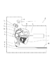
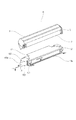
ここで、図21を用いて、カートリッジBの概略構成について説明する。図21は、カートリッジの構成を表す分解斜視図である。図21に示すように、カートリッジBは、感光体ドラム2とクリーニング枠体9を備えるクリーニング装置Cと、不図示の現像剤担持体と現像枠体13を備える現像装置Dから構成される。
Here, a schematic configuration of the cartridge B will be described with reference to FIG. FIG. 21 is an exploded perspective view showing the configuration of the cartridge. As shown in FIG. 21, the cartridge B includes a cleaning device C that includes the
現像枠体13の現像開口形成面13aには、現像装置Dの現像剤収容室に収容される現像剤が外部に漏れないようにするために封止フィルム103が溶着されている。
A
また、現像枠体13には引抜き開口101が設けられており、現像フィルム103は、その先端103cが引っ張られることにより、引抜き開口101を通じて現像枠体13の外側方向である矢印X方向に引き出される。このように、現像フィルム103は、引き抜かれることによって現像枠体13から取り除かれる。
Further, the developing
ここで、封止フィルム103を現像枠体13から取り除く前後において、引抜き開口101から現像剤が漏れるのを防ぐ必要がある。従来、例えば特許第3142746号公報に示すように、熱可塑性エラストマやスポンジ等の発泡性弾性部材からなる封止部材902を引抜き開口101に挿入することにより現像剤の漏れを防ぐ対策がとられていた。
Here, it is necessary to prevent the developer from leaking from the drawing opening 101 before and after removing the sealing
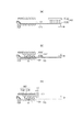
ここで、封止部材902の構成として想定される一例を図22に示す。図22(a)乃至図22(c)は、封止部材902の引抜き開口101への挿入前後における図であって、図21の切断線P1における概略断面図である。なお、P1は、図21において、矢印X方向に平行な線である。
Here, an example assumed as a configuration of the
図22(a)に示すように、封止部材902は、基板902aと、基板902aから直立したフィン902bで構成されている。そして、図22(b)に示すように、封止部材902は、封止フィルム103が矢印X方向に張力をかけられた状態で、矢印X方向と逆方向から引抜き開口101に挿入されている。そして、フィン902bは、封止フィルム103に対して所定の角度θを持って当接するように配置されている。このため、図22(c)に示すように、封止フィルム103を引抜き開口101から引き抜く際に、封止フィルム103と当接するフィン902bが、封止フィルム103に付着した現像剤を拭き取る。その結果、現像剤が引抜き開口101から外部に漏れ出ることを抑制することができる。
As shown in FIG. 22A, the sealing
本発明は上述したような封止部材の構成を更に発展させたものである。すなわち、本発明は、封止部材を取り付ける作業を簡略化する方法、および封止部材を取り付ける工程が簡略化できるプロセスカートリッジや現像装置を提供することを目的とする。 The present invention is a further development of the structure of the sealing member as described above. That is, an object of the present invention is to provide a method for simplifying the operation of attaching the sealing member, and a process cartridge and a developing device that can simplify the process of attaching the sealing member.
本発明の代表的な構成は、
画像形成装置に用いられる現像装置において、
現像剤を収容する現像剤収容室と、前記現像剤収容室の内部から外部に現像剤を供給すための現像開口を備える枠体と、
前記現像開口を封止するとともに、前記枠体に設けられる引抜き開口から引き抜かれることで前記現像開口から取り外しが可能な第1封止部材と、
前記第1封止部材が前記引抜き開口から引き抜かれる際に前記第1封止部材と摺擦し、前記引抜き開口から現像剤が前記枠体の外部に漏れるのを防ぐ第2封止部材と、
を有し、
前記第2封止部材は、前記第1封止部材と前記引き抜き開口の間の空間に熱可塑性エラストマを注入することで、前記枠体に一体成形されることを特徴とする。
A typical configuration of the present invention is as follows:
In a developing device used in an image forming apparatus,
A developer storage chamber for storing the developer, and a frame including a development opening for supplying the developer from the inside of the developer storage chamber to the outside;
A first sealing member that seals the development opening and is removable from the development opening by being pulled out from a drawing opening provided in the frame;
A second sealing member that slides against the first sealing member when the first sealing member is pulled out from the pull-out opening and prevents the developer from leaking out of the frame body from the pull-out opening;
Have
The second sealing member is integrally formed with the frame body by injecting a thermoplastic elastomer into a space between the first sealing member and the drawing opening.
また、本発明の別の構成は、
画像形成装置に用いられる現像装置において、
現像剤を収容する現像剤収容室と、前記現像剤収容室の内部から外部に現像剤を供給すための現像開口を備える枠体と、
前記現像開口を封止するとともに、前記枠体に設けられる引抜き開口から引き抜かれることで前記現像開口から取り外しが可能な第1封止部材と、
前記第1封止部材が前記引抜き開口から引き抜かれる際に前記第1封止部材と摺擦し、前記引抜き開口から現像剤が前記枠体の外部に漏れるのを防ぐ第2封止部材と、
を有し、
前記第2封止部材には抜け止め部が設けられ、前記抜け止め部は前記枠体に設けられた規制部と係合することで、前記第2封止部材が前記第1封止部材の引き抜き方向へ移動するのを規制することを特徴とする現像装置を提供することを特徴とする。
Another configuration of the present invention is as follows.
In a developing device used in an image forming apparatus,
A developer storage chamber for storing the developer, and a frame including a development opening for supplying the developer from the inside of the developer storage chamber to the outside;
A first sealing member that seals the development opening and is removable from the development opening by being pulled out from a drawing opening provided in the frame;
A second sealing member that slides against the first sealing member when the first sealing member is pulled out from the pull-out opening and prevents the developer from leaking out of the frame body from the pull-out opening;
Have
The second sealing member is provided with a retaining portion, and the retaining portion is engaged with a restricting portion provided on the frame body, so that the second sealing member is connected to the first sealing member. A developing device characterized by restricting movement in the drawing direction is provided.
また本発明にかかる現像装置の組み立て方法の代用的な様態は、
現像剤を収容する現像剤収容室と、前記現像剤収容室の内部から外部に現像剤を供給すための現像開口と、前記現像開口を封止する第1封止部材を引き抜くための引き抜き開口とを備える枠体を用意し、
前記現像開口に前記第1封止部材を取り付けて前記現像開口を封止した状態で、前記前記第1封止部材と前記現像開口との間の空間に熱可塑性エラストマを注入することで第2封止部材を形成して、前記引き抜き開口を封止することを特徴とする。
An alternative aspect of the method of assembling the developing device according to the present invention is as follows:
A developer accommodating chamber for accommodating the developer; a developing opening for supplying the developer from the inside of the developer accommodating chamber to the outside; and a pulling opening for pulling out the first sealing member that seals the developing opening. Prepare a frame with
In a state where the first sealing member is attached to the developing opening and the developing opening is sealed, a second thermoplastic elastomer is injected into a space between the first sealing member and the developing opening. A sealing member is formed to seal the drawing opening.
また本発明にかかる現像装置の組み立て方法の別の様態は、
現像剤を収容する現像剤収容室と、前記現像剤収容室の内部から外部に現像剤を供給すための現像開口と、前記現像開口を封止する第1封止部材を引き抜くための引き抜き開口と、前記引き抜き開口を封止する第2封止部材が前記第1封止部材の引き抜き方向に移動するのを規制する規制部と、を備える枠体を用意し、
前記現像開口に前記第1封止部材を取り付けて前記現像開口を封止した状態で、前記第2封止部材を前記現像開口に挿入して前記引き抜き開口を封止するとともに、前記第2封止部材を前記引き抜き開口に挿入する過程で、前記第2封止部材に設けた抜け止め部を前記規制部と係合させることを特徴とする。
Another aspect of the assembling method of the developing device according to the present invention is as follows.
A developer accommodating chamber for accommodating the developer; a developing opening for supplying the developer from the inside of the developer accommodating chamber to the outside; and a pulling opening for pulling out the first sealing member that seals the developing opening. And a regulating part that regulates movement of the second sealing member that seals the extraction opening in the extraction direction of the first sealing member, and prepares a frame body,
With the first sealing member attached to the developing opening and sealing the developing opening, the second sealing member is inserted into the developing opening to seal the pull-out opening, and the second sealing In the process of inserting a stop member into the pull-out opening, a retaining portion provided on the second sealing member is engaged with the restricting portion.
封止部材を取り付ける作業を簡略化する方法、および封止部材を取り付ける工程が簡略化できるプロセスカートリッジや現像装置を提供することができる。 It is possible to provide a method for simplifying the operation of attaching the sealing member, and a process cartridge and a developing device that can simplify the process of attaching the sealing member.
(画像形成装置の全体構成)
図1を用いて、本実施例に係る電子写真画像形成装置の一形態であるレーザビームプリンタ(以下、画像形成装置という)の全体構成の概略について説明する。図1は、本実施例に係る画像形成装置の全体構成を示す概略断面図である。本実施例に係る画像形成装置本体Aは、主な構成要素として、レーザスキャナ1、給紙カセット3、ピックアップローラ4、圧接部材5、転写ローラ6、定着装置7、排出ローラ8、搬送手段を備えている。ここで、搬送手段とは、紙等の記録媒体を給紙カセット3から画像形成装置の外部まで搬送する手段をいい、ピックアップローラ4や排出ローラ8等により構成される。また、本実施例に係る画像形成装置においては、画像形成装置本体Aに対して着脱可能なプロセスカートリッジ(以下、カートリッジという)Bが設けられている。
(Overall configuration of image forming apparatus)
An overall configuration of a laser beam printer (hereinafter referred to as an image forming apparatus) which is an embodiment of the electrophotographic image forming apparatus according to the present embodiment will be described with reference to FIG. FIG. 1 is a schematic cross-sectional view illustrating the overall configuration of the image forming apparatus according to the present embodiment. The main body A of the image forming apparatus according to this embodiment includes a laser scanner 1, a
図2を用いて、本実施例に係るカートリッジBについて説明する。図2は、本実施例に係るカートリッジを示す概略断面図である。本実施例に係るカートリッジBは、主な構成要素として、クリーニングユニットCと、現像装置としての現像ユニットDとを備えている。クリーニングユニットCは、像担持体としての電子写真感光体(以下、感光体ドラムという)2、クリーニング枠体9、クリーニングブレード10、帯電ローラ11を備えている。感光体ドラム2と帯電ローラ11は、クリーニング枠体9に回転可能に支持されており、互いに当接して設けられている。また、クリーニングブレード10は、クリーニング枠体9に締結されており、その先端が感光体ドラム2に当接するように設けられている。また、クリーニング枠体9は、クリーニングブレード10によって除去された廃トナーを収容する廃トナー容器9aを備えている。
The cartridge B according to the present embodiment will be described with reference to FIG. FIG. 2 is a schematic cross-sectional view showing the cartridge according to the present embodiment. The cartridge B according to this embodiment includes a cleaning unit C and a developing unit D as a developing device as main components. The cleaning unit C includes an electrophotographic photosensitive member (hereinafter referred to as a photosensitive drum) 2 as an image carrier, a cleaning frame 9, a
また、現像ユニットDは、現像剤担持体12、現像枠体(枠体)13、現像ブレード14、攪拌部材15を備えている。現像枠体13は、現像剤としてのトナーTを収容する現像剤収容室13bと、現像剤担持体12が設けられる現像室13cを備えている。現像剤担持体12は、現像枠体13に回転可能に支持されている。現像ブレード14は、現像枠体13に締結されており、現像剤担持体12と当接して設けられている。攪拌部材15は、現像剤収容室13b内において現像枠体13に回転可能に支持されている。
The developing unit D includes a
また、現像枠体13には、現像室13cと現像剤収容室13bとを連通するための現像開口13dが設けられている。そして、カートリッジBの未使用状態においては、現像開口13dを封止する第1封止部材として封止フィルム103が現像枠体13に溶着されることで現像開口13dは封止されている。カートリッジBの使用時に、ユーザが封止フィルム103を取り除くことによって、現像剤収容室13bに収容されるトナーTが、攪拌部材15によって撹拌搬送され現像室13cに移動可能となる。
The developing
次に、図1及び図2を参照して、本実施例に係る画像形成装置の画像形成動作の概略について説明する。まず、帯電ローラ11が感光体ドラム2の表面を帯電する。そして、レーザスキャナ1が、帯電された感光体ドラム2の表面に画像情報に基づいたレーザ光Lを露光することにより、感光体ドラム2上(像担持体上)に静電潜像を形成する。
Next, an outline of an image forming operation of the image forming apparatus according to the present embodiment will be described with reference to FIGS. First, the charging
一方、現像剤収容室13b内の攪拌部材15が、現像剤収容室13bに収容されるトナーTを攪拌し、現像枠体13に設けられた現像開口13dを通じて、現像室13c内の現像剤担持体12にトナーTを搬送する。現像剤担持体12に供給されたトナーTは、現像剤担持体12が図2中の矢印R方向に回転することによって現像ブレード14に至る。そして、現像ブレード14は、現像剤担持体12上のトナーTの層厚を規制して所望の帯電電荷量を付与すると共に、所定のトナー薄層を形成する。形成されたトナー薄層は、感光体ドラム2と現像剤担持体12とが近接する領域に搬送される。そして、現像剤担持体12に印加された現像バイアスによって感光体ドラム2上にトナーTが供給されることにより静電潜像が現像され、感光体ドラム2上にトナー像が形成される。
On the other hand, the agitating
また、トナー像の形成と同期して、紙、OHPシート、布等の記録媒体Mが、給紙カセット3から、ピックアップローラ4及び圧接部材5によって、一枚ずつ分離給送される。給送された記録媒体Mは、搬送ガイド(不図示)に沿って転写ローラ6へと搬送される。そして、感光体ドラム2上に形成されるトナー像が、転写ローラ6によって、記録媒体Mに転写される。なお、転写の後、感光体ドラム2上に残留したトナーは、クリーニングブレード10によって廃トナーとして除去され、除去された廃トナーは、廃トナー容器9aに溜められることとなる。
In synchronism with the formation of the toner image, the recording medium M such as paper, an OHP sheet, and cloth is separated and fed one by one from the
その後、トナー像が転写された記録媒体Mは、搬送ガイドに沿って定着装置7へと搬送される。そして、定着装置7が備える駆動ローラ7aと定着回転体7bが、記録媒体Mに熱及び圧力を印加することによって、記録媒体M上にトナー像が定着される。トナー像が定着された記録媒体Mは、排出ローラ8に搬送され、画像形成装置の外部へと排出される。以上のような動作によって、本実施例に係る画像形成装置による画像形成が完了することとなる。
Thereafter, the recording medium M on which the toner image is transferred is conveyed to the fixing device 7 along the conveyance guide. Then, the driving
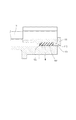
(封止フィルムの取り付け構成)
次に、図3を用いて、本実施例に係る封止フィルム103の取り付け構成について説明する。図3は、封止フィルムの取り付けの様子を継時的に表す斜視図である。そして、図3(a)は、封止フィルム103を現像枠体13に取り付ける前の状態を表す斜視図である。図3(b)は、封止フィルム103を現像枠体13に取り付ける最中の状態を表す斜視図である。図3(c)は、封止フィルム103を現像枠体13に取り付けた状態を表す斜視図である。
(Installation structure of sealing film)
Next, the attachment structure of the sealing
図3(a)に示すように、封止フィルム103は、現像開口13dの長手方向と略直交する矢印Z方向において、現像枠体13に設けられる現像開口13dの縁部である現像開口形成面13aに溶着される。ここで、封止フィルム103のうち、現像枠体13に溶着される側の面を現像開口内側面103aとする。そして、図3(b)に示すように、溶着された封止フィルム103は、折り返し部103bで矢印Xの方向に折り返された後、折り返された側の先端103cが、現像枠体13に形成される引抜き開口101に挿入される。そして、その先端103cは、図3(c)に示すように、現像枠体13の外側に引き出される。以上のようにして、封止フィルム103が、現像開口13dを封止するように現像枠体13へと取り付けられる。
As shown in FIG. 3A, the sealing
(実施例1)
(封止部材の構成)
次に、図4、図5を用いて、実施例1に係る封止部材102について説明する。詳細は後述するが封止部材102は、引き抜き開口101を封止して、引き抜き開口101から現像剤が外部に漏れ出るのを抑える第2封止部材である。
Example 1
(Configuration of sealing member)
Next, the sealing
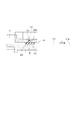
図4は、実施例1に係るカートリッジの未使用時の状態を示す斜視図である。図5は、実施例1に係る封止部材を説明するための概略断面図である。そして、図5(a)は、封止部材の説明をするための図であって、図4のカートリッジの長手方向に平行する切断線P2における概略断面図である。図5(b)は、封止部材の説明をするための図であって、図4のカートリッジの長手方向に直交する切断線P3における概略断面図である。図5(c)は、図4の矢印Xの方向の逆方向に向かって見た時の側面図である。なお、図5においては、説明の便宜上、現像剤担持体12、現像ブレード14等は削除して描いた。
FIG. 4 is a perspective view illustrating a state when the cartridge according to the first embodiment is not used. FIG. 5 is a schematic cross-sectional view for explaining the sealing member according to the first embodiment. FIG. 5A is a diagram for explaining the sealing member, and is a schematic cross-sectional view taken along a cutting line P2 parallel to the longitudinal direction of the cartridge of FIG. FIG. 5B is a diagram for explaining the sealing member, and is a schematic cross-sectional view taken along a cutting line P3 perpendicular to the longitudinal direction of the cartridge of FIG. FIG.5 (c) is a side view when it sees toward the reverse direction of the direction of the arrow X of FIG. In FIG. 5, the
カートリッジBの未使用状態においては、封止フィルム103が現像枠体13に溶着されることで現像開口13dを封止している。このため、現像剤収容室13bは密封されており、現像剤収容室13b内に収容されるトナーTは、現像室13cに供給されていない状態である。この状態において、図4に示すように、封止フィルム103の先端103cは、引抜き開口101から矢印X方向に引き出されている。
In the unused state of the cartridge B, the sealing
そして、実施例1に係る現像ユニットDにおいては、現像剤封止部材(以下、単に、封止部材という)102が、現像剤収容室13b内に収容されるトナーTが引抜き開口101から漏れないように現像枠体13に設けられている。実施例1において、封止部材102は、熱可塑性エラストマが充填されることによって現像枠体13に対して一体成形されている。図5(b)に示すように、引抜き開口101の隅部101a〜101dまで熱可塑性エラストマが充填されるため、引抜き開口101との間に隙間なく封止部材102が成形されることとなる。
In the developing unit D according to the first embodiment, the developer sealing member (hereinafter simply referred to as a sealing member) 102 prevents the toner T stored in the
また、図5(a)に示すように、封止部材102における封止フィルム103の引抜き方向(X方向)の最上流部には、封止フィルム103に付着したトナーTを掻き取るための掻き取り部109が設けられている。ここで、封止フィルム103を引き抜く方向における封止部材102の上流側の側面と、封止部材102の封止フィルムとの摺擦面とがなす角度を当接角θと定義する。実施例1においては、図5(a)に示すように、当接角θは90°以下になるように設定されている。
Further, as shown in FIG. 5A, the most upstream portion in the drawing direction (X direction) of the sealing
また、実施例1においては、図5(a)及び図5(c)に示すように、現像枠体13には、抜け止部材111が設けられている。この抜け止部材111の抜け止部112が、封止部材102における封止フィルム103の引抜き方向(X方向)の最下流部の受部110に当接することによって、封止部材102が引抜き開口101から抜け出ないようなっている。
In Example 1, as shown in FIGS. 5A and 5C, the developing
また、図5(c)に示すように、抜け止部材111は、抜け止部112が引抜き開口101内に入り込むように設けられており、また、ビスを締結することによって現像枠体13に固定されている。なお、図5(a)に示すように、カートリッジBは抜け止部材111の幅X1分だけ長手方向に大型化することとなる。また、抜け止部材111の一端に形成される側面111aと、引抜き開口101の一端に形成される底面101hとの間には、封止フィルム103を抜き出すための隙間Z1が設けられている。この隙間Z1は、封止フィルム103を抜き取れるよう封止フィルム103の厚みZ2よりも大きくなるように設けられている。
As shown in FIG. 5C, the retaining
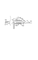
(封止部材の成形工程)
次に、図6乃至図8を用いて、実施例1に関わる封止部材の成型工程について説明する。図6及び図7は、実施例1に係る封止部材の成形工程を表す図であって、図6(a)、図6(b)、図7(a)は、図4の切断線P2における概略断面図、図6(c)、図7(b)は、図4の切断線P3における概略断面図である。図8は、射出成形後に第1及び第2金型を引抜き開口から取り外した状態における現像枠体を示す図である。そして、図8(a)は、図4の切断線P2における断面図、図8(b)は、図4の矢印Xの方向の逆方向に向かって見た時の現像枠体の側面図である。
(Molding process of sealing member)
Next, the molding process of the sealing member according to the first embodiment will be described with reference to FIGS. 6 and 7 are diagrams illustrating a molding process of the sealing member according to the first embodiment, and FIGS. 6A, 6B, and 7A illustrate the cutting line P2 in FIG. FIG. 6C and FIG. 7B are schematic cross-sectional views taken along the cutting line P3 in FIG. FIG. 8 is a view showing the developing device frame in a state in which the first and second molds are removed from the drawing opening after the injection molding. 8A is a cross-sectional view taken along the cutting line P2 in FIG. 4, and FIG. 8B is a side view of the developing device frame as viewed in the direction opposite to the direction of the arrow X in FIG. is there.
実施例1において、封止フィルム103を現像枠体13に取り付けた状態において、封止部材102は、熱可塑性エラストマを射出成形することで設けられるものである。まず、図6(a)に示すように、封止部材102を成形する際に封止フィルム103のたるみをなくすため、封止フィルム103の先端103cには、封止フィルム103が現像枠体13から剥がれない程度の張力が、矢印X方向にかけられている。このように、封止フィルム103の先端に103cに張力がかけられた状態にて、成形型としての第1の金型105と第2の金型106が引抜き開口101内に挿入される。そして、第1の金型105、第2の金型106、封止フィルム103、及び現像枠体13によって、引抜き開口101内に封止部材102を形成するための封止部材形成空間107が形成される。
In Example 1, the sealing
図6(a)及び図6(b)に示すように、第1の金型105には、前記封止部材形成空間107を形成する面である掻き取り部形成面105aが設けられている。この掻き取り部形成面105aは、封止フィルム103とのなす角度θが90°以下になるように形成されている。また、第2の金型106には、前記封止部材形成空間107を形成する面である受け部形成面106aが設けられている。ここで、図6(c)に示すように、引抜き開口101のうち封止フィルム103が設けられる側と反対側の面を引抜き開口天面101eとする。つまり、封止部材形成空間107は、より具体的には、掻き取り部形成面105a、受け部形成面106a、引抜き開口天面101e、封止フィルム103の現像開口内側面103a、引抜き開口第1側面101f、引抜き開口第2側面101gによって形成される。
As shown in FIGS. 6A and 6B, the
図6(a)に示すように、第2の金型106には、封止部材形成空間107に熱可塑性エラストマを注入するための注入ノズル108が設けられている。この注入ノズル108から矢印X方向と逆の方向に熱可塑性エラストマが射出される。そして、図6(b)に示すように、注入ノズル108の先端に設けられたノズル先端108aから封止部材形成空間107内に熱可塑性エラストマが充填されていく。そして、図6(c)に示すように、注入ノズル108から射出された熱可塑性エラストマは、矢印Y方向に拡がっていくことにより、引抜き開口101の隅部101a〜101dに向かって充填されていく。
As shown in FIG. 6A, the
その結果、図7(a)及び図7(b)に示すように、封止部材102が封止部材形成空間107に隙間なく成形されることとなる。すなわち、引抜き開口の隅部101a〜d等に製造上の形状のバラツキがあった場合であっても、そのバラツキに沿うように熱可塑性エラストマが充填されることとなる。このように、実施例1において、封止部材102は、封止部材形成空間107に隙間なく、現像枠体13に対して一体成形されることとなる。すなわち、図8(a)及び図8(b)に示すように、第1の金型105及び第2の金型106を取り外した状態においても、封止部材102は、安定した形態を維持することができる。
As a result, as shown in FIGS. 7A and 7B, the sealing
なお、現像枠体13を構成するモノマーのうち、主たるモノマーが封止部材102に含まれていることが好ましい。すなわち、封止部材102を形成するための熱可塑性エラストマは、現像枠体13と同系の材質からなることが好ましい。材料再生時に部品同士の分解を行わなくて済むためである。実施例1においては、ハイインパクトポリスチレンからなる現像枠体13に、スチレン系の熱可塑性エラストマからなる封止部材102を成形した。しかし、これに限らず、上記材質の他の樹脂であっても同様の機械的特性を持つものであれば良い。
In addition, it is preferable that the main monomer is contained in the sealing
(封止部材の作用)
次に、図8を参照して、実施例1に係る封止部材102の作用について説明する。カートリッジBの未使用状態において、封止フィルム103は現像開口13dを封止しているため、現像開口内側面103aのうち現像剤収容室13b側の面にはトナーTが付着している。カートリッジBを初めて使用する際は、図8(a)に示すように、ユーザが引抜き開口101から現像枠体13の外部に露出する封止フィルム103の先端103cを矢印X方向に引っ張ることにより、封止フィルム103を引抜き開口101から引き抜く。この際、現像枠体13に溶着されている封止フィルム103は、折り返し部103bから次第に引き剥がされていく。このとき、トナーTが付着している現像開口内側面103aが、封止部材102の掻き取り部109に摺擦することによって、封止フィルム103に付着するトナーTが掻き取られることとなる。したがって、封止フィルム103を引抜き開口101から引き抜いた際に、封止フィルム103に付着したトナーTが、現像枠体13外部(枠体外部)に漏れることを抑制することができる。
(Operation of sealing member)
Next, the operation of the sealing
さらに、図9を用いて、トナーTの掻き取りについての詳細について説明する。図9は、封止部材の掻き取り性能について説明する図である。図9(a)は、当接角θが90°よりも大きい場合における掻き取り部の拡大概略断面図である。図9(b)は、当接角θが90°以下の場合、すなわち実施例1における掻き取り部の拡大概略断面図である。なお、図9において、点線部分は、封止フィルム103を矢印X方向に引っ張る前の封止部材の状態を表し、ハッチングされた部分は、封止フィルム103を矢印X方向に引っ張った後の封止部材の状態を表す。図9(a)において、封止フィルム103と封止部材121との摺動面のうち封止フィルム103の抜き取り方向の最上流側の側面を上流側側面120、トナーTを掻き取る部分を掻き取り部119とする。また、封止フィルム103を矢印X方向に引っ張った後においては、掻き取り部119a、上流側側面120aとする。
Further, details of scraping off the toner T will be described with reference to FIG. FIG. 9 is a diagram illustrating the scraping performance of the sealing member. FIG. 9A is an enlarged schematic cross-sectional view of the scraping portion when the contact angle θ is larger than 90 °. FIG. 9B is an enlarged schematic cross-sectional view of the scraping portion in the first embodiment when the contact angle θ is 90 ° or less, that is, FIG. In FIG. 9, the dotted line portion represents the state of the sealing member before the sealing
封止フィルム103に引き抜くために矢印X方向に張力をかけることによって掻き取り部102に剪断力が働く。図9(a)に示すように、当接角θを90°より大きくした場合、封止部材121の上流側側面120が反ることとなり、掻き取り部119がめくれてしまう。掻き取り部119がめくれると、上流側側面120aが封止フィルム103に当接することとなる。これを腹当たり現象という。腹当たり現象が生じると、図9(a)に示すように、掻き取り部119aは、封止フィルム103に対してエッジ当接をしなくなる。その結果、掻き取り部119のエッジによる封止フィルム103の掻き取り性能が低下することとなり、封止フィルム103に付着したトナーTを十分に掻き取れなくなってしまう。
A shearing force is applied to the scraping
一方、図9(b)に示すように、当接角θを90°以下に設定した場合、掻き取り部109への剪断力が上流側側面118に対してカウンタ方向に働くため、上流側側面118の反りが少ない。その結果、上流側側面118aの反りによる掻き取り部109aのめくれを抑制することができるため、腹当たり現象の発生を抑制することができる。したがって、掻き取り部109aは、封止フィルム103とのエッジ当接を維持することができるため、トナーTの拭き取り性能を維持することができる。
On the other hand, as shown in FIG. 9B, when the contact angle θ is set to 90 ° or less, the shearing force to the scraping
以上述べたように、引抜き開口101から現像枠体13の外部にトナーTが漏れることを抑制する効果をより発揮するためには、当接角θが90°以下であることが望ましい。
As described above, the contact angle θ is desirably 90 ° or less in order to further exert the effect of suppressing the leakage of the toner T from the
次に、図10を用いて、封止フィルム103が外部に引き抜かれた後の状態の現像枠体13について説明する。図10は、封止フィルムが取り除かれた後の状態の封止部材を示す図であって、図4中の切断線P2における概略断面図である。図10に示すように、封止部材102は、封止フィルム103が現像枠体13の外部に引き抜かれた後も引抜き開口101内に保持されるため、カートリッジBの使用中においても引抜き開口101からトナーTが漏れることを抑制することができる。
Next, the developing
以上述べたように、実施例1においては、封止部材102を用いることによって、引抜き開口101からトナーTが漏れ出るのを抑制することができる。また、実施例1に係る封止部材102は、現像枠体13に一体成形されるため、封止フィルム103に付着したトナーTを安定的に掻き取ることができる。
As described above, in the first embodiment, by using the sealing
(他の構成との比較)
ここで本実施例の効果を明らかにするため、図22(a)、(b)、(c)に比較例としての封止部材902を示す。比較例は本実施例と異なり、あらかじめ成形された封止部材902を引き抜き開口101に挿入する構成である。
(Comparison with other configurations)
Here, in order to clarify the effect of the present embodiment, FIGS. 22A, 22B, and 22C show a sealing
上記比較例の封止部材902を用いて現像開口を封止する場合、組立て時に封止部材902の表裏判別を行った上で、フィン902bが封止フィルム103に当接する向きに合わせて引抜き開口101に挿入することが必要となる。
When the developing opening is sealed using the sealing
更に言うと、現像枠体13の引抜き開口101に封止部材902を挿入する構成を採用する場合、図23に示す引抜き開口101の隅部101a〜dから現像剤が漏れないように、封止部材902と引抜き開口101の寸法を厳密に管理する必要がある。そのため、コストアップが生じてしまうことが懸念される。
Furthermore, when adopting the configuration in which the sealing
これに対して、本実施例の構成であれば、プロセスカートリッジの引き抜き開口101に封止部材102を挿入する工程が不要であり、カートリッジBの生産性が向上する。また、封止部材102は、引き抜き開口101の形に合わせて形成されるため、あらかじめ封止部材を引き抜き開口101の寸法に合わせて形成する必要がない。つまり封止部材と引き抜き開口の厳密な寸法管理が不要である。よりカートリッジBの生産性を向上させ、コストアップを抑制することができる。
On the other hand, with the configuration of the present embodiment, the step of inserting the sealing
(実施例2)
次に、図11及び図12を用いて、実施例2に係る現像枠体と封止部材について説明する。図11は、実施例2に係るカートリッジの未使用時の状態を示す斜視図である。図12は、図11の切断線P2における封止部材の構成を示す概略断面図である。なお、実施例1と同一の構成部分については同一の符号を付して、その説明は省略する。
(Example 2)
Next, the developing device frame and the sealing member according to Example 2 will be described with reference to FIGS. 11 and 12. FIG. 11 is a perspective view illustrating a state when the cartridge according to the second embodiment is not used. FIG. 12 is a schematic cross-sectional view showing the configuration of the sealing member along the cutting line P2 in FIG. In addition, the same code | symbol is attached | subjected about the component same as Example 1, and the description is abbreviate | omitted.
図11に示すように、実施例2において、実施例1と同様に、封止フィルム103の先端103cは、引抜き開口101を通じて矢印X方向に案内されることにより、引抜き開口101から現像枠体13の外部に引き出されている。また、図12に示すように、実施例2に係る封止部材102は、実施例1と同様に、当接角θが90°以下となるように設けられている。
As shown in FIG. 11, in Example 2, as in Example 1, the
実施例2においては、図11及び図12に示すように、現像枠体13には、封止部材102が一体成形される領域に溝部としての注入穴204が設けられている。図11において、注入穴204の中心を通りつつ、カートリッジの長手方向に平行な線を切断線P2と定義する。図12に示すように、引抜き開口101及び注入穴204の内部に封止部材202が成形されている。この封止部材202のうち注入穴204の内部に形成される部分を抜け止部212とする。この抜け止部212が、封止部材102が引抜き開口101から現像枠体13の外部に抜け落ちてしまうことを防止する。
In the second embodiment, as shown in FIGS. 11 and 12, the developing
図12に示すように、封止部材202の一部としての抜け止部212は、注入穴204内に形成されている。封止フィルム103を引き抜く際に、剪断力が掻き取り部209に働く。この剪断力によって、封止部材202は、現像枠体13の外部に抜ける方向に力を受けるが、実施例2においては、抜け止部212が注入穴204の抜け止め壁面204aと当接するため、引抜き開口101から抜け落ちない。すなわち注入穴204は、現像枠体13に設けられた規制部であって、抜け止め部212と係合することで封止部材202が移動するのを規制する(抑える)。
As shown in FIG. 12, the retaining
次に、図13を用いて、実施例2における封止部材の成形工程について説明する。図13は、実施例2に係る封止部材の成形工程について説明する概略断面図である。図13(a)に示すように、封止部材202の射出成形前においては、封止フィルム103は、現像枠体13に溶着されており、封止フィルム103の先端103cに矢印X方向に張力がかけられた状態で現像開口13dを封止している。この状態において、第1の金型205と第2の金型206が引抜き開口101内に挿入されることにより、引抜き開口101内に封止部材形成空間207が形成されることとなる。図13(a)に示すように、封止部材形成空間207は、掻き取り部形成面205a、受け部形成面206a、引抜き開口天面101e、現像開口内側面103a、引抜き開口第1側面101f、引抜き開口第2側面101g、注入穴204とから構成される。ここで、引抜き開口第1側面101f、引抜き開口第2側面101gとは、図6(c)で示す実施例1のものと同様の面を指す。
Next, the molding process of the sealing member in Example 2 will be described using FIG. FIG. 13 is a schematic cross-sectional view illustrating the molding process of the sealing member according to the second embodiment. As shown in FIG. 13A, before the sealing
図13(b)に示すように、注入ノズル208から矢印Z方向に熱可塑性エラストマを射出することで、注入ノズル208の先端に設けられたノズル先端208aから注入穴204を介して封止部材形成空間207内に熱可塑性エラストマが充填されていく。そして、図13(c)に示すように、封止部材形成空間207内に隙間なく封止部材202が現像枠体13に対して一体成形されることとなる。
As shown in FIG. 13B, a sealing member is formed from the
以上述べたように、実施例2においては、封止部材202を用いることによって、引抜き開口101からトナーTが漏れ出るのを抑制することができる。また、実施例2に係る封止部材202は、現像枠体13に一体成形されるため、封止フィルム103に付着したトナーTを安定的に掻き取ることができる。また、組立て時に厳密な寸法管理が不要であるため、生産性を向上させ、コストアップを抑制することができる。さらに、実施例2に係る封止部材202は、抜け止部212を備えているため、実施例1で用いた別部材としての抜け止部材111を設ける必要がない。したがって、抜け止部材111の幅X1分(図5(a)参照)、カートリッジの長手方向における大型化を抑制することができ、また、コストアップを抑制することができる。
As described above, in the second embodiment, the use of the sealing
(実施例3)
次に、図14を用いて、実施例3に係る封止部材と現像枠体について説明する。図14は、実施例3に係る封止部材と現像枠体について説明する図である。図14(a)は、実施例3に係る枠体と封止部材を示す概略断面図である。図14(b)は、実施例3に係る封止部材の概略斜視図である。図14(c)は、実施例3に係る枠体と封止部材を示す断面図であって、図14(a)の切断線P4における概略断面図である。なお、実施例1又は実施例2と同一の構成部分については同一の符号を付して、その説明は省略する。
(Example 3)
Next, the sealing member and the developing device frame according to the third embodiment will be described with reference to FIG. FIG. 14 is a diagram illustrating the sealing member and the developing frame according to the third embodiment. FIG. 14A is a schematic cross-sectional view illustrating a frame body and a sealing member according to the third embodiment. FIG. 14B is a schematic perspective view of the sealing member according to the third embodiment. FIG.14 (c) is sectional drawing which shows the frame and sealing member which concern on Example 3, Comprising: It is a schematic sectional drawing in the cutting line P4 of Fig.14 (a). In addition, the same code | symbol is attached | subjected about the component same as Example 1 or Example 2, and the description is abbreviate | omitted.
図14(a)に示すように、実施例3においては、実施例1と同様に、封止フィルム103の先端103cは、引抜き開口101を通じて矢印X方向に案内されることにより、引抜き開口101から現像枠体13の外部に引き出されている。また、実施例3に係る封止部材302は、実施例1と同様に、当接角θが90°以下となるように設けられている。また、実施例3に係る封止部材302は、実施例1と同様に、熱可塑性エラストマを射出成形することによって現像枠体13に対して一体成形されている。そのため、引抜き開口101の隅部101a〜101d(図8(b)参照)に隙間なく熱可塑性エラストマが充填されている。したがって、隅部101a〜101d等の製造上の形状のバラツキによらず、引抜き開口101に隙間なく封止部材302が成形される。
As shown in FIG. 14A, in Example 3, as in Example 1, the
また、実施例2と同様に、引抜き開口101及び注入穴304の内部に封止部材302が成形されている。この注入穴304に形成される抜け止部312によって、封止部材302が、引抜き開口101から現像枠体13の外部に抜け落ちることを防止できる。封止フィルム103を引抜き開口101から引き抜く際、抜け止部312が注入穴304の抜け止め壁面304aと当接し、矢印X方向への動きが規制されるためである。
As in the second embodiment, a sealing
上記構成に加えて、図14に示すように、実施例3に係る封止部材302は、第2抜け止部315を有している。図14(b)に示すように、第2抜け止部315は、第2抜け止端部315a、315bと、第2抜け止下部315cとを有している。第2抜け止部315は、図14(a)に示すように、現像枠体13に設けられた第2抜け止め穴(第2の規制部)316内に形成されている。第2抜け止部315は、封止フィルム103の引抜き時に封止部材302が引抜き開口101から抜け出ることを抑制する。また、第2抜け止部315は、第2抜け止め穴316aの側面と当接しているため、側面316aからの反力によって、図9(a)に示したような上流側側面の反り変形を抑制する。その結果、当接角θの増加を抑えることによって、掻き取り部309が90°以下を保ったままトナーTを掻き取ることができる。すなわち、封止フィルム103を引き抜く際に良好なトナーTの掻き取り性を確保することができる。
In addition to the above configuration, as illustrated in FIG. 14, the sealing
以上述べたように、実施例3においては、封止部材302を用いることによって、引抜き開口101からトナーTが漏れ出るのを抑制することができる。また、実施例3に係る封止部材202は、現像枠体13に対して一体成形されるため、封止フィルム103に付着したトナーTを安定的に掻き取ることができる。また、組立て時に厳密な寸法管理が不要であるため、生産性を向上させ、コストアップを抑制することができる。さらに、実施例3に係る封止部材302は、抜け止部312を備えているため、実施例1で用いた別部材としての抜け止部材111を設ける必要がない。したがって、カートリッジBの長手方向における大型化を抑制することができ、また、コストアップを抑制することができる。さらに、実施例3に係る封止部材302は、第2抜け止部315を備えており、封止フィルム103を抜き取る際に、当接角θが増加することを抑制することができるため良好な掻き取り性を確保することができる。
As described above, in the third embodiment, by using the sealing
(実施例4)
実施例1から3では、熱可塑性エラストマを引き抜き開口101に注入して成形することで、カートリッジBに封止部材を取り付ける際の作業の効率化を図った。
Example 4
In Examples 1 to 3, the thermoplastic elastomer was injected into the
一方、本実施例では、上述の実施例とは異なり、成形済みの封止部材702を、引き抜き開口101に挿入して取り付ける場合に、カートリッジBの組み立て工程を簡略化する方法について説明する。詳細は後述するが、本実施例では、引き抜き開口101から封止部材702が外れることを防止するための抜け止め部を、封止部材に形成したことを特徴とする。
On the other hand, in this embodiment, unlike the above-described embodiment, a method for simplifying the assembly process of the cartridge B when the molded sealing
(封止部材の構成)
本実施例の封止部材702の構成について、図15、図16を用いて説明する。
(Configuration of sealing member)
The configuration of the sealing
先ず、図2に示すように、カートリッジBの未使用状態においては、現像剤封止フィルム103が現像開口形成面13aに溶着されることで現像開口13dを封止している。このため、トナーTは現像剤収容部13b内に密封されており、現像室13c内には供給されていない状態である。
First, as shown in FIG. 2, in the unused state of the cartridge B, the
図15(a)は、カートリッジBの未使用時における現像枠体13、現像剤封止フィルム103、及び抜け止め部材702eの斜視図である。なお、封止部材702の構成を説明するため、上述の現像剤担持体12、現像ブレード14等は図15から削除している。
FIG. 15A is a perspective view of the developing
図15(a)に示すように、現像剤封止フィルム103の先端103cは、引抜き開口101を通して矢印X方向に案内されることにより、引抜き開口101から引き出されている。
As shown in FIG. 15A, the
ここで、図15(a)において、長手方向に平行する線を切断線P2と定義する。また、図15(b)は、図15(a)における封止部材702の分解斜視図である。封止部材702は後述するように、現像剤封止フィルム103が矢印X方向に引き伸ばされた状態にて引抜き開口101内に挿入されることによって設けられる。
Here, in FIG. 15A, a line parallel to the longitudinal direction is defined as a cutting line P2. FIG. 15B is an exploded perspective view of the sealing
図16は、図15(a)の切断線P2における封止部材702の構成を表す概略断面図である。図16に示すように、引抜き開口101内には現像剤封止フィルム103が設けられており、現像剤封止フィルム103の先端103cは矢印X方向に引き出されている。引抜き開口101の内部には封止部材702が設けられている。封止部材702は、現像剤封止フィルム103に付着したトナーTを拭き取るためのフィン702bと、現像剤封止フィルム103の引抜き時に封止部材702が引抜き開口101から抜け出ることを防ぐための抜け止め部702eと、を備えている。
FIG. 16 is a schematic cross-sectional view showing the configuration of the sealing
また、封止部材702は、前述のフィン702b及び抜け止め部702eを支持する基板702aを有する。フィン702bは封止フィルム103との摺擦部であり、かつ現像剤(トナーT)の拭き取り部である。そして後述するようにフィン702bは可撓性を有する。またフィン702bと抜け止め部702eは基板702aを挟んでそれぞれ反対側に設けられる。
The sealing
また、封止部材702は、図15(b)に示すように、基板702aは矢印Y方向に幅Y1を持って設けられており、抜け止め部702eは矢印Y方向に幅Y2を持って設けられている。なお、抜け止め部702eの幅Y2は、基板702aの幅Y1に対して小さく設定されている。
As shown in FIG. 15B, the sealing
ここで、図16に示すように、フィン702bの先端に設けられた拭き取り部702b2と、現像剤封止フィルム103の現像開口内側面103aとのなす角度を当接角θと定義する。
Here, as shown in FIG. 16, the angle formed by the wiping portion 702b2 provided at the tip of the
本実施例においては、図16に示すように、複数のフィン702bが矢印X方向下流側に撓んだ状態にて拭き取り部702b2が現像開口内側面103aと当接している。抜け止め部702eは、基板702aに設けられた凸部であって、引抜き開口101内の引抜き開口天面101eに設けられた開口部(以下、「抜け止め穴」と呼ぶ)104内に係合して設けられている。現像剤封止フィルム103を引抜く際、拭き取り部702b2が現像剤封止フィルム103と摺擦することで矢印X方向の剪断力を受けるため、封止部材702が矢印X方向に抜けようとする。この時、抜け止め部702eに設けられた抜け止め下流側側面702e3が、抜け止め穴104に設けられた抜け止め壁面104aと当接することにより、封止部材702が引抜き開口101から矢印X方向に抜け出ることを防止する。即ち、抜け止め穴104は、抜け止め部702eが係合する封止部材702が、現像剤封止フィル103の引抜き方向に移動するのを規制する規制部として機能する。
In this embodiment, as shown in FIG. 16, the wiping portion 702b2 is in contact with the developing opening
ここで、本実施例の封止部材702は、熱可塑性エラストマからなる成形品を引抜き開口101内に挿入することで設けられるものである。熱可塑性エラストマとしては、現像枠体13と同系の材質からなる熱可塑性エラストマであれば材料再生時に部品同士の分解を行わなくて済むため、好ましい。そこで本実施例では、ハイインパクトポリスチレンからなる現像枠体13に、スチレン系熱可塑性エラストマからなる封止部材702を成形しているが、上記材質の他の樹脂でも同様の機械的特性を持つものであれば良い。封止部材702の挿入工程について次に説明する。
Here, the sealing
(封止部材の挿入工程)
本実施例の封止部材702を引抜き開口101内に挿入する工程について、図16及び図18を用いて説明する。
(Inserting process of sealing member)
A process of inserting the sealing
尚、図18(a)〜(c)はそれぞれ、封止部材702の挿入前、挿入開始時、及び挿入途中における、図15の切断線P2での概略断面図である。
18A to 18C are schematic cross-sectional views taken along the cutting line P2 in FIG. 15 before, at the start of, and during the insertion of the sealing
図18(a)に示すように、封止部材702を挿入する際に現像剤封止フィルム103のたるみを除くため、現像剤封止フィルム103の先端103cには、現像剤封止フィルム103が現像枠体13から除去されない程度の張力を矢印X方向にかけられている。また、封止部材702のフィン702bは、図18(b)に示すように6個設けられており、全て同じ形状である。
As shown in FIG. 18A, in order to remove the slack of the
フィン702bは、矢印X方向最上流側に設けられたフィン上流側側面702b1と、現像剤封止フィルム103の現像開口内側面側103aに付着したトナーTを拭き取る拭き取り部702b2と、を有している。また、フィン702bは、基板702aに保持されるフィン根元702b3と、矢印X方向最下流側に設けられたフィン下流側側面702b4とを有している。加えて、封止部材702の抜け止め部702eは、矢印X方向最上流側に設けられた抜け止め上流側側面702e1と、抜け止め天面702e2と、矢印X方向最下流側に設けられた抜け止め下流側側面702e3と、を有している。また、抜け止め部702eは、基板702aに保持される抜け止め根元702e4を有している。更に、封止部材702の基板702aは、基板底面702c及びフィン根元702b3からなる基板下部702dと、基板天面702f及び抜け止め根元702e4からなる基板上部702gとから構成される。なお、抜け止め天面101e2、基板天面702f、及び基板底面702cは略平行になるよう設けられている。
The
図18(b)に示すように、封止部材702を矢印X方向と逆方向に引抜き開口101内に挿入する際は、基板702aの矢印X方向最上流側に設けられた基板先端面702hから引抜き開口101内に入り込んでいく。この時、複数のフィン702bのうち、矢印X方向上流側に設けられたフィン702j1から現像開口内側面103aと当接し、矢印X方向下流側に撓んでいく。この時、フィン702bの撓みによって、拭き取り部702b2は、現像剤封止フィルム103の現像開口内側面103aから矢印Z方向の反力を受ける。封止部材702を続けて矢印X方向と逆方向に挿入していくと、フィン702j1に続いて矢印X方向下流側に設けられたフィン702j2、フィン702j3が順次現像開口内側面103aと当接し、矢印X方向下流側に撓んでいく。この時、抜け止め上流側側面702e1が引抜き開口101の入口である引抜き開口外面101iに当接する。次に、抜け止め上流側側面702e1は、開口外面101iと摺動しながら矢印Z方向と逆方向に案内されることによって、すでに引抜き開口101内に挿入されたフィン702j1〜j3が更に図18(b)に示した高さZ3の寸法分撓み、前述した反発力が上昇する。
As shown in FIG. 18B, when the sealing
なお、抜け止め部702eの高さZ3より、フィン702j1〜j3の高さ(図18(b)において上下方向の高さ)を十分に高くしてある。そのため抜け止め部702eが上に突出していても、フィン702j1〜j3を撓ませることで、封止部材702を引き抜き開口101に挿入可能な構成となっている。
Note that the height of the fins 702j1 to j3 (the height in the vertical direction in FIG. 18B) is sufficiently higher than the height Z3 of the retaining
封止部材702を矢印X方向と逆方向に更に挿入していくと、図18(c)に示すように抜け止め部702eよりも矢印X方向下流側に設けられたフィン702j4〜j6が順次現像剤封止フィルム103の現像開口内側面103aと当接し、矢印X方向下流側に撓んでいく。従って、全てのフィン702bが、現像開口内側面103aと当接して矢印X方向下流側に撓む。フィン702bの撓みによって、拭き取り部702b2は、現像剤封止フィルム103の現像開口内側面103aから矢印Z方向の反力を受けている。この反力によって抜け止め天面702e2が引抜き開口天面101eと当接するため、基板702aと引抜き開口天面101eが略平行な状態になっている。抜け止め天面702e2と引抜き開口天面101e、及び、拭き取り部702b2と現像剤封止フィルム103の現像開口内側面103aが摺擦しながら、封止部材702は引抜き開口101内に挿入されていく。封止部材702を更に引抜き開口101内に挿入していくと、引抜き開口天面101eに抜け止め穴104が設けられているため、抜け止め天面702e2と引抜き開口天面101eとの当接状態が解除される。このとき、拭き取り部702b2が現像開口内側面103aから受けている矢印Z方向の反力によって、抜け止め部702eが矢印Z方向に抜け止め穴104内に入り込んでいく。ここで、抜け止め部702eは、基板天面702fと引抜き開口天面101eとが当接するまで抜け止め穴104内に入り込む。基板天面702fと引抜き開口天面101eとが当接すると、複数のフィン702bの撓みが図18(b)に示した高さZ3の寸法分解放されることによって、図16に示すように拭き取り部702b2が当接角θを持って現像開口内側面103aと当接した状態になる。
When the sealing
(封止部材の作用)
本実施例の封止部材702の作用について図15〜図19を用いて説明する。
(Operation of sealing member)
The effect | action of the sealing
図2に示すように、現像剤封止フィルム103は現像剤収容部13bのトナーTを封止しているため、現像開口内側面103aにはトナーTが付着している。カートリッジBを初めて使用する際は、図15に示すように、現像枠体13の外側に引き出された現像剤封止フィルム103を、ユーザが矢印X方向に引っ張ることにより、現像剤封止フィルム103が現像開口形成面13aから引き剥がされ始める。このとき、図2に示した現像開口内側面103aは、図16(a)に示すように現像剤封止フィルム103の折り返し部103bから矢印X方向に引っ張られるため、拭き取り部702b2が現像開口内側面103aと摺擦することでトナーTを拭き取る。このことから、現像剤封止フィルム103の現像開口内側面103aに付着したトナーTが、引抜き開口101から外に出ることを防げる。従って、現像剤封止フィルム103を引抜く際に引抜き開口101からのトナーTの漏れを防止することができる。
As shown in FIG. 2, since the
ここで、図17は、現像剤封止フィルム103が現像枠体13の外側に引抜かれた後における、図15の切断線P2における封止部材702の構成を表す断面図である。図17に示すように、封止部材702は、現像剤封止フィルム103が現像枠体13の外側に引抜かれた後も引抜き開口101内に保持されるため、カートリッジの使用中においても引抜き開口101からのトナーTの漏れを防止することができる。
Here, FIG. 17 is a cross-sectional view illustrating the configuration of the sealing
(従来例との比較)
ここで、本実施例の効果を明らかにするため、比較例としての封止部材902を、図24(a)(b)(c)に示す。これらは封止部材902の断面図である。
(Comparison with conventional example)
Here, in order to clarify the effect of the present embodiment, a sealing
比較例としての封止部材902を用いて現像剤を封止する場合、現像剤封止フィルム103を引抜く際にフィン902bが現像剤封止フィルム103と摺擦するため、フィン902bには矢印X方向の剪断力が加わる。このため、封止部材902が矢印X方向の剪断力によって引抜き開口101から抜け出ることを防止するための抜け止め手段が必要である。そこで、図24(c)に示すように引抜き開口101の外側に抜け止め部材111を設ける場合がある。
When the developer is sealed using the sealing
しかしながら、図24(c)に示すように抜け止め部材111を別体で設ける場合、抜け止め部材111の長手幅X2分のスペースを確保する必要がある。そのため、プロセスカートリッジが大型化し、それに伴って電子写真画像形成装置が大型化したりする場合がある。また、プロセスカートリッジ内の他の部品配置に制約が生じる場合が考えらえる。更に、長手幅X2分のスペースを確保するためにフィン902bの配置個数を減らした封止部材を用いる場合には、フィン902bの拭き取り性の低下を防ぐために封止部材902及び引抜き開口101の寸法を厳密に管理する必要がある。そのため、コストアップの一因となっていた。また、別部材としての抜け止め部材111を設けると部品費や組立の工数が増えるため、更なるコストアップの一因となることが考えられる。
However, when the retaining
これに対して、本実施例では抜け止め部702eが基板702a上に設けられているため、長手幅X2を確保する必要がなくなる。このため、本実施例の封止部材702を用いることによって長手幅の削減を図ることが可能となる。また、従来のように別部材としての抜け止め部材111(図24(c)参照)を取り付ける作業が短縮されるので組み立て工程の簡略化が可能となる。
On the other hand, in this embodiment, since the retaining
一方、抜け止め部材111として用いていた長手幅X2の分だけ本実施例の封止部材702のフィン702bの個数を増やした場合を考える。図19は、図16の封止部材702に対して、長手幅X2分のスペースを用いることで配置可能なフィン414を追加した封止部材402の概略断面図である。
On the other hand, consider the case where the number of
封止部材402を用いることによって、現像剤封止フィルム103を引抜き開口101から矢印X方向に引抜く際の、拭き取り部402b2による拭き取り回数が追加されたフィン414の個数分だけ増える。従って、更なる現像剤封止フィルム103の拭き取り性の向上を図ることができる。加えて、本実施例の封止部材702を用いることにより、図24(c)に示した封止部材902と抜け止め部材111との一体化によるコスト低減を図ることが可能となる。
By using the sealing member 402, the number of times of wiping by the wiping portion 402b2 when the
本実施例では、図16に示したように、封止部材702用いて抜け止め部702eによる現像剤封止フィルム103の引抜き時の抜け止め作用について述べた。しかし、この抜け止め部の位置は、図20(a)に示す封止部材502のように複数のフィン502bに対して矢印X方向上流側に配置した構成でも良い。
In this embodiment, as shown in FIG. 16, the retaining action when the
加えて、本実施例では、図15(b)に示したように、抜け止め部702eの矢印Y方向の幅Y2が基板702aの幅Y1よりも小さく設定された構成で説明した。しかし、この抜け止め部の幅は、図20(b)に示す封止部材602のように基板602aの幅Y1と同等にして設けてもよい。図20(a)及び図20(b)に示した封止部材502、602のいずれを用いた場合においても、本実施例にて説明した封止部材702と同等の効果を得ることができる。
In addition, in this embodiment, as shown in FIG. 15B, the configuration in which the width Y2 of the retaining
以上説明したように、本実施例の封止部材702、502、602を用いることによって、現像剤封止フィルムを引抜き開口から引抜く際に、現像剤封止フィルムに付着した現像剤の拭き取りを行いつつ、封止部材が引抜き開口から抜け出ることを防止できる。しかも、抜け止め手段による長手幅の増加やコストアップをもたらすことはない。封止部材702を引き出し開口101に取り付ける工程も簡略化可能である。
As described above, by using the sealing
すなわち本実施例によれば、成形済みの封止部材702を引き抜き開口101に挿入してカートリッジBに取り付ける場合であっても、カートリッジBの組み立て工程を簡略化することができる。封止部材702を引き抜き開口101に挿入する過程で、抜け止め部702eを抜け止め穴(規制部)104と係合させることができる。
That is, according to the present embodiment, even when the molded sealing
上記各実施例においては、ユーザが封止フィルム103を引き抜く方式の現像装置としての現像ユニットDについて説明した。しかしながら、カートリッジB内部に設けた自動引抜き機構を用いて、自動的に封止フィルム103が引き抜かれる構成を用いたものに本実施例に係る封止部材を適用してもよい。また、現像ユニットDをカートリッジBの一部として一体的に構成したものについて説明したが、現像ユニットDを画像形成装置本体Aに単独で組み付けたものに本実施例に係る封止部材を適用してもよい。また、画像形成装置の一例としてレーザビームプリンタを用いて説明したが、複写機やファクシミリ装置等に本実施例に係る封止部材を適用してもよい。
In each of the above embodiments, the developing unit D as a developing device in which a user pulls out the sealing
Claims (12)
現像剤を収容する現像剤収容室と、前記現像剤収容室の内部から外部に現像剤を供給すための現像開口を備える枠体と、
前記現像開口を封止するとともに、前記枠体に設けられる引抜き開口から引き抜かれることで前記現像開口から取り外しが可能な第1封止部材と、
前記第1封止部材が前記引抜き開口から引き抜かれる際に前記第1封止部材と摺擦し、前記引抜き開口から現像剤が前記枠体の外部に漏れるのを防ぐ第2封止部材と、
を有し、
前記第2封止部材は、前記第1封止部材と前記引き抜き開口の間の空間に熱可塑性エラストマを注入することで、前記枠体に一体成形されることを特徴とする現像装置。 In a developing device used in an image forming apparatus,
A developer storage chamber for storing the developer, and a frame including a development opening for supplying the developer from the inside of the developer storage chamber to the outside;
A first sealing member that seals the development opening and is removable from the development opening by being pulled out from a drawing opening provided in the frame;
A second sealing member that slides against the first sealing member when the first sealing member is pulled out from the pull-out opening and prevents the developer from leaking out of the frame body from the pull-out opening;
Have
The developing device according to claim 1, wherein the second sealing member is integrally formed with the frame body by injecting a thermoplastic elastomer into a space between the first sealing member and the drawing opening.
現像剤を収容する現像剤収容室と、前記現像剤収容室の内部から外部に現像剤を供給すための現像開口を備える枠体と、
前記現像開口を封止するとともに、前記枠体に設けられる引抜き開口から引き抜かれることで前記現像開口から取り外しが可能な第1封止部材と、
前記第1封止部材が前記引抜き開口から引き抜かれる際に前記第1封止部材と摺擦し、前記引抜き開口から現像剤が前記枠体の外部に漏れるのを防ぐ第2封止部材と、
を有し、
前記第2封止部材には抜け止め部が設けられ、前記抜け止め部は前記枠体に設けられた規制部と係合することで、前記第2封止部材が前記第1封止部材の引き抜き方向へ移動するのを規制することを特徴とする現像装置。 In a developing device used in an image forming apparatus,
A developer storage chamber for storing the developer, and a frame including a development opening for supplying the developer from the inside of the developer storage chamber to the outside;
A first sealing member that seals the development opening and is removable from the development opening by being pulled out from a drawing opening provided in the frame;
A second sealing member that slides against the first sealing member when the first sealing member is pulled out from the pull-out opening and prevents the developer from leaking out of the frame body from the pull-out opening;
Have
The second sealing member is provided with a retaining portion, and the retaining portion is engaged with a restricting portion provided on the frame body, so that the second sealing member is connected to the first sealing member. A developing device that restricts movement in a drawing direction.
前記抜け止め部は、前記拭き取り部が設けられた側とは反対側に突出した凸部であって、
前記凸部の高さは前記拭き取り部の高さより低いことを特徴とする請求項6または7に記載の現像装置。 The rubbing portion of the second sealing member with the first sealing member is provided with a flexible wiping portion for wiping off the developer attached to the first sealing member,
The retaining portion is a convex portion protruding to the opposite side to the side where the wiping portion is provided,
The developing device according to claim 6, wherein a height of the convex portion is lower than a height of the wiping portion.
潜像が形成される像担持体と、
請求項1乃至8のいずれか1項に記載の現像装置と、
を有することを特徴とするプロセスカートリッジ。 In a process cartridge that can be attached to and detached from the main body of an image forming apparatus,
An image carrier on which a latent image is formed;
A developing device according to any one of claims 1 to 8,
A process cartridge comprising:
現像剤を収容する現像剤収容室と、前記現像剤収容室の内部から外部に現像剤を供給すための現像開口と、前記現像開口を封止する第1封止部材を引き抜くための引き抜き開口とを備える枠体を用意し、
前記現像開口に前記第1封止部材を取り付けて前記現像開口を封止した状態で前記前記第1封止部材と前記現像開口との間の空間に熱可塑性エラストマを注入することで第2封止部材を形成して、前記引き抜き開口を封止することを特徴とする現像装置の組み立て方法。 In the assembling method of the developing device,
A developer accommodating chamber for accommodating the developer; a developing opening for supplying the developer from the inside of the developer accommodating chamber to the outside; and a pulling opening for pulling out the first sealing member that seals the developing opening. Prepare a frame with
A second seal is obtained by injecting a thermoplastic elastomer into a space between the first sealing member and the development opening in a state where the first sealing member is attached to the development opening and the development opening is sealed. A developing device assembling method, wherein a stop member is formed and the drawing opening is sealed.
前記規制部に前記熱可塑性エラストマを充填することで、前記第2封止部材に前記規制部と係合するための抜け止め部を形成することを特徴とする請求項10に記載の現像装置の組み立て方法。 The frame is provided with a restricting portion for restricting the second sealing member from moving in the pulling direction of the first sealing member,
The developing device according to claim 10, wherein a retaining portion for engaging the restriction portion is formed in the second sealing member by filling the thermoplastic elastomer into the restriction portion. Assembly method.
現像剤を収容する現像剤収容室と、前記現像剤収容室の内部から外部に現像剤を供給すための現像開口と、前記現像開口を封止する第1封止部材を引き抜くための引き抜き開口と、前記引き抜き開口を封止する第2封止部材が前記第1封止部材の引き抜き方向に移動するのを規制する規制部と、を備える枠体を用意し、
前記現像開口に前記第1封止部材を取り付けて前記現像開口を封止した状態で、前記第2封止部材を前記引き抜き開口に挿入して前記引き抜き開口を封止するとともに、前記第2封止部材を引き抜き開口に挿入する過程で、前記第2封止部材に設けた抜け止め部を前記規制部と係合させることを特徴とする現像装置の組み立て方法。 In the assembling method of the developing device,
A developer accommodating chamber for accommodating the developer; a developing opening for supplying the developer from the inside of the developer accommodating chamber to the outside; and a pulling opening for pulling out the first sealing member that seals the developing opening. And a regulating part that regulates movement of the second sealing member that seals the extraction opening in the extraction direction of the first sealing member, and prepares a frame body,
With the first sealing member attached to the developing opening and sealing the developing opening, the second sealing member is inserted into the drawing opening to seal the drawing opening, and the second sealing A developing device assembling method, wherein a retaining portion provided on the second sealing member is engaged with the restricting portion in the process of inserting the retaining member into the pull-out opening.
Priority Applications (2)
| Application Number | Priority Date | Filing Date | Title |
|---|---|---|---|
| JP2012234028A JP5460812B2 (en) | 2011-11-15 | 2012-10-23 | Developing device, process cartridge, and assembling method of developing device |
| US13/676,311 US8965243B2 (en) | 2011-11-15 | 2012-11-14 | Developing apparatus, process cartridge and method for assembling developing apparatus |
Applications Claiming Priority (5)
| Application Number | Priority Date | Filing Date | Title |
|---|---|---|---|
| JP2011249893 | 2011-11-15 | ||
| JP2011249893 | 2011-11-15 | ||
| JP2012101130 | 2012-04-26 | ||
| JP2012101130 | 2012-04-26 | ||
| JP2012234028A JP5460812B2 (en) | 2011-11-15 | 2012-10-23 | Developing device, process cartridge, and assembling method of developing device |
Publications (2)
| Publication Number | Publication Date |
|---|---|
| JP2013242512A true JP2013242512A (en) | 2013-12-05 |
| JP5460812B2 JP5460812B2 (en) | 2014-04-02 |
Family
ID=48524103
Family Applications (1)
| Application Number | Title | Priority Date | Filing Date |
|---|---|---|---|
| JP2012234028A Expired - Fee Related JP5460812B2 (en) | 2011-11-15 | 2012-10-23 | Developing device, process cartridge, and assembling method of developing device |
Country Status (2)
| Country | Link |
|---|---|
| US (1) | US8965243B2 (en) |
| JP (1) | JP5460812B2 (en) |
Cited By (2)
| Publication number | Priority date | Publication date | Assignee | Title |
|---|---|---|---|---|
| JP2019148648A (en) * | 2018-02-26 | 2019-09-05 | キヤノン株式会社 | Development device |
| WO2020007345A1 (en) * | 2018-07-05 | 2020-01-09 | 珠海天威飞马打印耗材有限公司 | Sealing assembly for toner cartridge, toner cartridge and recycling method therefor |
Families Citing this family (6)
| Publication number | Priority date | Publication date | Assignee | Title |
|---|---|---|---|---|
| JP5456142B2 (en) | 2011-11-09 | 2014-03-26 | キヤノン株式会社 | Developer container and process cartridge |
| JP6057651B2 (en) * | 2012-10-01 | 2017-01-11 | キヤノン株式会社 | Process cartridge and process cartridge manufacturing method |
| JP6381378B2 (en) * | 2014-09-04 | 2018-08-29 | キヤノン株式会社 | Developing device, process cartridge, and image forming apparatus |
| JP6459614B2 (en) * | 2015-02-24 | 2019-01-30 | 富士ゼロックス株式会社 | Developing device and image forming apparatus using the same |
| KR102135780B1 (en) | 2015-02-27 | 2020-07-20 | 캐논 가부시끼가이샤 | Drum unit, cartridge and process cartridge |
| JP6486148B2 (en) | 2015-02-27 | 2019-03-20 | キヤノン株式会社 | Image forming apparatus and cartridge |
Citations (3)
| Publication number | Priority date | Publication date | Assignee | Title |
|---|---|---|---|---|
| JPH07128980A (en) * | 1993-11-01 | 1995-05-19 | Canon Inc | Developing, device, process cartridge, image forming device and method for attaching sealing member |
| JPH0926743A (en) * | 1995-07-11 | 1997-01-28 | Canon Inc | Process cartridge and developing device and image forming device |
| JP2008040430A (en) * | 2006-08-10 | 2008-02-21 | Fuji Xerox Co Ltd | Toner cartridge and image forming apparatus using the same |
Family Cites Families (6)
| Publication number | Priority date | Publication date | Assignee | Title |
|---|---|---|---|---|
| JP3142746B2 (en) * | 1995-06-16 | 2001-03-07 | キヤノン株式会社 | Developing device, cartridge and image forming apparatus |
| JP2954140B2 (en) * | 1998-02-27 | 1999-09-27 | 新潟日本電気株式会社 | Toner cartridge |
| US6654575B2 (en) * | 2000-11-28 | 2003-11-25 | Canon Kabushiki Kaisha | Developer container having sealing member |
| US8099012B2 (en) * | 2007-12-18 | 2012-01-17 | Lexmark International, Inc. | Developer roll lip seal |
| JP4968957B2 (en) | 2008-03-31 | 2012-07-04 | キヤノン株式会社 | Frame body unit, developing device and process cartridge, and frame body unit, developing device and process cartridge manufacturing method |
| JP5456142B2 (en) | 2011-11-09 | 2014-03-26 | キヤノン株式会社 | Developer container and process cartridge |
-
2012
- 2012-10-23 JP JP2012234028A patent/JP5460812B2/en not_active Expired - Fee Related
- 2012-11-14 US US13/676,311 patent/US8965243B2/en not_active Expired - Fee Related
Patent Citations (3)
| Publication number | Priority date | Publication date | Assignee | Title |
|---|---|---|---|---|
| JPH07128980A (en) * | 1993-11-01 | 1995-05-19 | Canon Inc | Developing, device, process cartridge, image forming device and method for attaching sealing member |
| JPH0926743A (en) * | 1995-07-11 | 1997-01-28 | Canon Inc | Process cartridge and developing device and image forming device |
| JP2008040430A (en) * | 2006-08-10 | 2008-02-21 | Fuji Xerox Co Ltd | Toner cartridge and image forming apparatus using the same |
Cited By (3)
| Publication number | Priority date | Publication date | Assignee | Title |
|---|---|---|---|---|
| JP2019148648A (en) * | 2018-02-26 | 2019-09-05 | キヤノン株式会社 | Development device |
| US11415910B2 (en) | 2018-02-26 | 2022-08-16 | Canon Kabushiki Kaisha | Developing apparatus having a sealed developer opening |
| WO2020007345A1 (en) * | 2018-07-05 | 2020-01-09 | 珠海天威飞马打印耗材有限公司 | Sealing assembly for toner cartridge, toner cartridge and recycling method therefor |
Also Published As
| Publication number | Publication date |
|---|---|
| US8965243B2 (en) | 2015-02-24 |
| JP5460812B2 (en) | 2014-04-02 |
| US20130142541A1 (en) | 2013-06-06 |
Similar Documents
| Publication | Publication Date | Title |
|---|---|---|
| JP5460812B2 (en) | Developing device, process cartridge, and assembling method of developing device | |
| JP5980064B2 (en) | Development device manufacturing method and process cartridge manufacturing method | |
| US9360831B2 (en) | Developing unit, process cartridge and image forming apparatus | |
| JP4345989B1 (en) | Developing device and electrophotographic image forming apparatus | |
| JP4894868B2 (en) | Container, supply device, and image forming apparatus | |
| CN107132747B (en) | Developing device, process cartridge, and image forming apparatus | |
| CN107678261B (en) | Cartridge and image forming apparatus | |
| JP4445022B2 (en) | Toner supply device and shutter structure | |
| JP2005107141A (en) | Toner supply device | |
| JP5585414B2 (en) | Powder container and powder processing apparatus using the same | |
| JP2019056851A (en) | Developer supply container and developer supply system | |
| JP2010197430A5 (en) | ||
| KR100523775B1 (en) | Remanufacturing method for developer supplying device | |
| JP2014071429A (en) | Process cartridge | |
| JP2007093697A (en) | Developer supply container | |
| JP5556617B2 (en) | Powder container and powder processing apparatus using the same | |
| JP6544309B2 (en) | Developing device and image forming apparatus provided with the same | |
| JP2009042717A (en) | Toner cartridge, method of making toner cartridge reusable, process cartridge and image forming apparatus | |
| JP2008203677A (en) | Toner cartridge | |
| JP2006154557A (en) | Image forming device | |
| JP6702684B2 (en) | Developer container, developing device, process cartridge, and image forming apparatus | |
| JP4419991B2 (en) | Shutter device, developer container, waste developer container, and image forming apparatus | |
| JP6618321B2 (en) | Developer container, developing device, process cartridge, and image forming apparatus | |
| JP2017191308A (en) | Developer container, developing device, process cartridge and image forming device | |
| JP2015225306A (en) | Toner container, toner supply device, and image forming apparatus |
Legal Events
| Date | Code | Title | Description |
|---|---|---|---|
| A131 | Notification of reasons for refusal |
Free format text: JAPANESE INTERMEDIATE CODE: A131 Effective date: 20131001 |
|
| A521 | Request for written amendment filed |
Free format text: JAPANESE INTERMEDIATE CODE: A523 Effective date: 20131202 |
|
| TRDD | Decision of grant or rejection written | ||
| A01 | Written decision to grant a patent or to grant a registration (utility model) |
Free format text: JAPANESE INTERMEDIATE CODE: A01 Effective date: 20131217 |
|
| A61 | First payment of annual fees (during grant procedure) |
Free format text: JAPANESE INTERMEDIATE CODE: A61 Effective date: 20140114 |
|
| LAPS | Cancellation because of no payment of annual fees |