JP2013239710A - Method of outputting variable wavelength light and light output device, optical interference tomographic device, and computer readable recording medium - Google Patents
Method of outputting variable wavelength light and light output device, optical interference tomographic device, and computer readable recording medium Download PDFInfo
- Publication number
- JP2013239710A JP2013239710A JP2013101981A JP2013101981A JP2013239710A JP 2013239710 A JP2013239710 A JP 2013239710A JP 2013101981 A JP2013101981 A JP 2013101981A JP 2013101981 A JP2013101981 A JP 2013101981A JP 2013239710 A JP2013239710 A JP 2013239710A
- Authority
- JP
- Japan
- Prior art keywords
- light
- wavelength
- gain medium
- optical
- wavelength tunable
- Prior art date
- Legal status (The legal status is an assumption and is not a legal conclusion. Google has not performed a legal analysis and makes no representation as to the accuracy of the status listed.)
- Pending
Links
Images


Classifications
-
- H—ELECTRICITY
- H05—ELECTRIC TECHNIQUES NOT OTHERWISE PROVIDED FOR
- H05B—ELECTRIC HEATING; ELECTRIC LIGHT SOURCES NOT OTHERWISE PROVIDED FOR; CIRCUIT ARRANGEMENTS FOR ELECTRIC LIGHT SOURCES, IN GENERAL
- H05B47/00—Circuit arrangements for operating light sources in general, i.e. where the type of light source is not relevant
- H05B47/10—Controlling the light source
-
- G—PHYSICS
- G01—MEASURING; TESTING
- G01B—MEASURING LENGTH, THICKNESS OR SIMILAR LINEAR DIMENSIONS; MEASURING ANGLES; MEASURING AREAS; MEASURING IRREGULARITIES OF SURFACES OR CONTOURS
- G01B9/00—Measuring instruments characterised by the use of optical techniques
- G01B9/02—Interferometers
- G01B9/0209—Low-coherence interferometers
- G01B9/02091—Tomographic interferometers, e.g. based on optical coherence
-
- H—ELECTRICITY
- H01—ELECTRIC ELEMENTS
- H01S—DEVICES USING THE PROCESS OF LIGHT AMPLIFICATION BY STIMULATED EMISSION OF RADIATION [LASER] TO AMPLIFY OR GENERATE LIGHT; DEVICES USING STIMULATED EMISSION OF ELECTROMAGNETIC RADIATION IN WAVE RANGES OTHER THAN OPTICAL
- H01S3/00—Lasers, i.e. devices using stimulated emission of electromagnetic radiation in the infrared, visible or ultraviolet wave range
- H01S3/05—Construction or shape of optical resonators; Accommodation of active medium therein; Shape of active medium
- H01S3/08—Construction or shape of optical resonators or components thereof
- H01S3/081—Construction or shape of optical resonators or components thereof comprising three or more reflectors
- H01S3/083—Ring lasers
-
- H—ELECTRICITY
- H01—ELECTRIC ELEMENTS
- H01S—DEVICES USING THE PROCESS OF LIGHT AMPLIFICATION BY STIMULATED EMISSION OF RADIATION [LASER] TO AMPLIFY OR GENERATE LIGHT; DEVICES USING STIMULATED EMISSION OF ELECTROMAGNETIC RADIATION IN WAVE RANGES OTHER THAN OPTICAL
- H01S3/00—Lasers, i.e. devices using stimulated emission of electromagnetic radiation in the infrared, visible or ultraviolet wave range
- H01S3/10—Controlling the intensity, frequency, phase, polarisation or direction of the emitted radiation, e.g. switching, gating, modulating or demodulating
- H01S3/10038—Amplitude control
-
- H—ELECTRICITY
- H01—ELECTRIC ELEMENTS
- H01S—DEVICES USING THE PROCESS OF LIGHT AMPLIFICATION BY STIMULATED EMISSION OF RADIATION [LASER] TO AMPLIFY OR GENERATE LIGHT; DEVICES USING STIMULATED EMISSION OF ELECTROMAGNETIC RADIATION IN WAVE RANGES OTHER THAN OPTICAL
- H01S3/00—Lasers, i.e. devices using stimulated emission of electromagnetic radiation in the infrared, visible or ultraviolet wave range
- H01S3/10—Controlling the intensity, frequency, phase, polarisation or direction of the emitted radiation, e.g. switching, gating, modulating or demodulating
- H01S3/106—Controlling the intensity, frequency, phase, polarisation or direction of the emitted radiation, e.g. switching, gating, modulating or demodulating by controlling devices placed within the cavity
- H01S3/1062—Controlling the intensity, frequency, phase, polarisation or direction of the emitted radiation, e.g. switching, gating, modulating or demodulating by controlling devices placed within the cavity using a controlled passive interferometer, e.g. a Fabry-Perot etalon
-
- H—ELECTRICITY
- H01—ELECTRIC ELEMENTS
- H01S—DEVICES USING THE PROCESS OF LIGHT AMPLIFICATION BY STIMULATED EMISSION OF RADIATION [LASER] TO AMPLIFY OR GENERATE LIGHT; DEVICES USING STIMULATED EMISSION OF ELECTROMAGNETIC RADIATION IN WAVE RANGES OTHER THAN OPTICAL
- H01S3/00—Lasers, i.e. devices using stimulated emission of electromagnetic radiation in the infrared, visible or ultraviolet wave range
- H01S3/23—Arrangements of two or more lasers not provided for in groups H01S3/02 - H01S3/22, e.g. tandem arrangements of separate active media
- H01S3/2383—Parallel arrangements
- H01S3/2391—Parallel arrangements emitting at different wavelengths
-
- H—ELECTRICITY
- H01—ELECTRIC ELEMENTS
- H01S—DEVICES USING THE PROCESS OF LIGHT AMPLIFICATION BY STIMULATED EMISSION OF RADIATION [LASER] TO AMPLIFY OR GENERATE LIGHT; DEVICES USING STIMULATED EMISSION OF ELECTROMAGNETIC RADIATION IN WAVE RANGES OTHER THAN OPTICAL
- H01S5/00—Semiconductor lasers
- H01S5/10—Construction or shape of the optical resonator, e.g. extended or external cavity, coupled cavities, bent-guide, varying width, thickness or composition of the active region
- H01S5/14—External cavity lasers
- H01S5/141—External cavity lasers using a wavelength selective device, e.g. a grating or etalon
-
- H—ELECTRICITY
- H01—ELECTRIC ELEMENTS
- H01S—DEVICES USING THE PROCESS OF LIGHT AMPLIFICATION BY STIMULATED EMISSION OF RADIATION [LASER] TO AMPLIFY OR GENERATE LIGHT; DEVICES USING STIMULATED EMISSION OF ELECTROMAGNETIC RADIATION IN WAVE RANGES OTHER THAN OPTICAL
- H01S5/00—Semiconductor lasers
- H01S5/40—Arrangement of two or more semiconductor lasers, not provided for in groups H01S5/02 - H01S5/30
- H01S5/4012—Beam combining, e.g. by the use of fibres, gratings, polarisers, prisms
-
- H—ELECTRICITY
- H01—ELECTRIC ELEMENTS
- H01S—DEVICES USING THE PROCESS OF LIGHT AMPLIFICATION BY STIMULATED EMISSION OF RADIATION [LASER] TO AMPLIFY OR GENERATE LIGHT; DEVICES USING STIMULATED EMISSION OF ELECTROMAGNETIC RADIATION IN WAVE RANGES OTHER THAN OPTICAL
- H01S3/00—Lasers, i.e. devices using stimulated emission of electromagnetic radiation in the infrared, visible or ultraviolet wave range
- H01S3/10—Controlling the intensity, frequency, phase, polarisation or direction of the emitted radiation, e.g. switching, gating, modulating or demodulating
- H01S3/105—Controlling the intensity, frequency, phase, polarisation or direction of the emitted radiation, e.g. switching, gating, modulating or demodulating by controlling the mutual position or the reflecting properties of the reflectors of the cavity, e.g. by controlling the cavity length
-
- H—ELECTRICITY
- H01—ELECTRIC ELEMENTS
- H01S—DEVICES USING THE PROCESS OF LIGHT AMPLIFICATION BY STIMULATED EMISSION OF RADIATION [LASER] TO AMPLIFY OR GENERATE LIGHT; DEVICES USING STIMULATED EMISSION OF ELECTROMAGNETIC RADIATION IN WAVE RANGES OTHER THAN OPTICAL
- H01S3/00—Lasers, i.e. devices using stimulated emission of electromagnetic radiation in the infrared, visible or ultraviolet wave range
- H01S3/10—Controlling the intensity, frequency, phase, polarisation or direction of the emitted radiation, e.g. switching, gating, modulating or demodulating
- H01S3/13—Stabilisation of laser output parameters, e.g. frequency or amplitude
- H01S3/131—Stabilisation of laser output parameters, e.g. frequency or amplitude by controlling the active medium, e.g. by controlling the processes or apparatus for excitation
- H01S3/1312—Stabilisation of laser output parameters, e.g. frequency or amplitude by controlling the active medium, e.g. by controlling the processes or apparatus for excitation by controlling the optical pumping
-
- H—ELECTRICITY
- H01—ELECTRIC ELEMENTS
- H01S—DEVICES USING THE PROCESS OF LIGHT AMPLIFICATION BY STIMULATED EMISSION OF RADIATION [LASER] TO AMPLIFY OR GENERATE LIGHT; DEVICES USING STIMULATED EMISSION OF ELECTROMAGNETIC RADIATION IN WAVE RANGES OTHER THAN OPTICAL
- H01S5/00—Semiconductor lasers
- H01S5/10—Construction or shape of the optical resonator, e.g. extended or external cavity, coupled cavities, bent-guide, varying width, thickness or composition of the active region
- H01S5/14—External cavity lasers
Abstract
Description
本発明は、波長可変光(wavelength−swept light)を出力する方法及び光出力装置、光干渉断層撮影装置、並びにコンピュータ読み取り可能な記録媒体に関する。 The present invention relates to a method and an optical output device, an optical coherence tomography apparatus, and a computer-readable recording medium for outputting wavelength-variable light (wavelength-swept light).
単色性(monochromaticity)、凝集性(coherence)、方向性(directionality)を有する光の特性を利用して、光は、現在多様な分野で活用されている。バイオ分野及び医療分野でも、光は、組職及び細胞の観察、病気の診断又はレーザ手術などで多様に活用されている。 Light is currently used in various fields by utilizing the characteristics of light having monochromaticity, coherence, and directionality. In the bio field and the medical field, light is used in various ways for organization, cell observation, disease diagnosis, laser surgery, and the like.
特に、医療分野で、上述のような光の特性によって、人体を直接切開せずに、人体の内部構造を観察することができるため、光を利用して、各種疾病の原因及び位置、並びに進行過程を容易に安全に把握することができる。高出力、連続発振(continuous wave)、波長可変(wavelength sweeping)のような、光を生成する技術の発達と共に、光透過の深さなどが改善され、リアルタイムで生きている組職又は細胞の断層映像(tomographic image)を、高解像度で獲得することができる。 In particular, in the medical field, the internal structure of the human body can be observed without directly incising the human body due to the characteristics of light as described above. The process can be grasped easily and safely. With the development of technology that generates light, such as high power, continuous wave, and wavelength sweeping, the depth of light transmission is improved, and the fault of living tissue or cells in real time Video (tomographic image) can be acquired with high resolution.
本発明は、上記従来技術に鑑みてなされたものであって、本発明の目的は、波長可変光(wavelength−swept light)を出力する方法及び光出力装置を提供することにある。
また、上記方法をコンピュータに実行させるためのプログラムを記録したコンピュータ読み取り可能な記録媒体を提供することにある。
また、上記光出力装置を備える光干渉断層撮影装置を提供することにある。
The present invention has been made in view of the above-described prior art, and an object of the present invention is to provide a method and an optical output device for outputting wavelength-variable light (wavelength-swept light).
Another object of the present invention is to provide a computer-readable recording medium on which a program for causing a computer to execute the above method is recorded.
Moreover, it is providing the optical coherence tomography apparatus provided with the said optical output device.
上記目的を達成するためになされた本発明の一態様による波長可変光を出力する光出力装置は、第1ゲイン媒質(gain medium)、第1波長可変フィルタ(wavelength−swept filter)、及び第1光共振部(optical resonance unit)を含み、第1波長可変光を生成する第1光生成部と、第2ゲイン媒質、第2波長可変フィルタ、及び第2光共振部を含み、前記第1波長可変光と異なる中心波長を有する第2波長可変光を生成する第2光生成部と、前記第1波長可変光及び前記第2波長可変光を結合して1つの第3波長可変光を出力する結合部と、前記第1ゲイン媒質と前記第2ゲイン媒質とにそれぞれ印加される電流の大きさ及び電流のオン/オフ時点のうちの少なくともいずれか一つを制御することにより、前記第1波長可変光及び前記第2波長可変光のそれぞれの出力サイズと波長領域とを制御する制御部と、を備える。 An optical output device that outputs wavelength tunable light according to an aspect of the present invention made to achieve the above object includes a first gain medium, a first wavelength tunable filter, and a first An optical resonance unit; a first light generation unit configured to generate first wavelength tunable light; a second gain medium; a second wavelength tunable filter; and a second optical resonance unit. A second light generation unit that generates a second wavelength variable light having a central wavelength different from that of the variable light, and the first wavelength variable light and the second wavelength variable light are combined to output one third wavelength variable light. At least one of the magnitude of the current applied to the coupling unit, the first gain medium, and the second gain medium, and the current on / off time, respectively. By controlling the One, and a control unit for controlling said first variable wavelength light and the respective output size and the wavelength region of the second variable wavelength light.
上記目的を達成するためになされた本発明の他の態様による波長可変光を出力する光出力装置は、第1ゲイン媒質、第1波長可変フィルタ、第1光共振部、及び第1光増幅器を含み、第1波長可変光を生成する第1光生成部と、第2ゲイン媒質、第2波長可変フィルタ、第2光共振部、及び第2光増幅器を含み、前記第1波長可変光と異なる中心波長を有する第2波長可変光を生成する第2光生成部と、前記第1波長可変光及び前記第2波長可変光を結合して1つの第3波長可変光を出力する結合部と、前記第1光増幅器と前記第2光増幅器とにそれぞれ印加される電流の大きさ及び電流のオン/オフ時点のうちの少なくともいずれか一つを制御することにより、前記第1波長可変光及び前記第2波長可変光のそれぞれの出力サイズと波長領域とを制御する制御部と、を備え、前記第1光生成部は、前記第1ゲイン媒質、前記第1波長可変フィルタ、及び前記第1光共振部を利用して生成された波長可変光を、前記第1光増幅器を利用して増幅することにより前記第1波長可変光を生成し、前記第2光生成部は、前記第2ゲイン媒質、前記第2波長可変フィルタ、及び前記第2光共振部を利用して生成された波長可変光を、前記第2光増幅器を利用して増幅することにより前記第2波長可変光を生成する。 An optical output device for outputting a wavelength tunable light according to another aspect of the present invention made to achieve the above object includes a first gain medium, a first wavelength tunable filter, a first optical resonator, and a first optical amplifier. And includes a first light generation unit that generates the first wavelength variable light, a second gain medium, a second wavelength variable filter, a second optical resonance unit, and a second optical amplifier, and is different from the first wavelength variable light. A second light generating unit that generates a second wavelength tunable light having a central wavelength, a combining unit that combines the first wavelength tunable light and the second wavelength tunable light and outputs one third tunable light; By controlling at least one of the magnitude of the current applied to each of the first optical amplifier and the second optical amplifier and the on / off time of the current, the first wavelength tunable light and the Each output size and wavelength range of the second tunable light A control unit that controls the wavelength variable light generated by using the first gain medium, the first wavelength tunable filter, and the first optical resonance unit. The first wavelength variable light is generated by amplifying using the first optical amplifier, and the second light generation unit includes the second gain medium, the second wavelength variable filter, and the second light. The second wavelength tunable light is generated by amplifying the wavelength tunable light generated using the resonating unit using the second optical amplifier.
上記目的を達成するためになされた本発明の更に他の態様による波長可変光を出力する光出力装置は、光の誘導放出(stimulated emission)と増幅とを利用して第1中心波長を有する光を放出する第1ゲイン媒質と、光の誘導放出と増幅とを利用して前記第1中心波長と異なる第2中心波長を有する光を放出する第2ゲイン媒質と、前記第1ゲイン媒質及び前記第2ゲイン媒質を並列に連結して前記第1ゲイン媒質及び前記第2ゲイン媒質で放出された光を共振させて移動させる第1光共振部と、前記第1ゲイン媒質及び前記第2ゲイン媒質で放出された光の波長を可変する波長可変フィルタと、前記第1光共振部と前記波長可変フィルタとを直列に連結し、前記波長可変フィルタによって可変された波長可変光を前記第1ゲイン媒質及び前記第2ゲイン媒質にフィードバックさせる第2光共振部と、前記第1ゲイン媒質によって生成される第1波長可変光と前記第2ゲイン媒質によって生成される第2波長可変光とが結合された1つの第3波長可変光を出力する結合部と、前記第1ゲイン媒質と前記第2ゲイン媒質とにそれぞれ印加される電流の大きさ及び電流のオン/オフ時点のうちの少なくともいずれか一つを制御することにより、前記第1波長可変光及び前記第2波長可変光のそれぞれの出力サイズと波長領域とを制御する制御部と、を備える。 An optical output device for outputting a wavelength tunable light according to still another aspect of the present invention, which is made to achieve the above object, is a light having a first central wavelength using stimulated emission and amplification of light. A first gain medium that emits light, a second gain medium that emits light having a second center wavelength different from the first center wavelength by utilizing stimulated emission and amplification of light, the first gain medium, and the A first optical resonance unit configured to connect a second gain medium in parallel to resonate and move light emitted from the first gain medium and the second gain medium; and the first gain medium and the second gain medium. A wavelength tunable filter that varies the wavelength of the light emitted from the first optical resonator, and the wavelength tunable filter connected in series, and the wavelength tunable light varied by the wavelength tunable filter A second optical resonator that feeds back to the first gain medium and the second gain medium; a first wavelength variable light generated by the first gain medium; and a second wavelength variable light generated by the second gain medium. At least one of a coupling unit that outputs one coupled third wavelength variable light, a magnitude of current applied to each of the first gain medium and the second gain medium, and a current on / off time point A control unit that controls the output size and the wavelength region of each of the first tunable light and the second tunable light by controlling one of them.
上記目的を達成するためになされた本発明の更に他の態様による波長可変光を出力する光出力装置は、光の誘導放出と増幅とを利用して第1中心波長を有する光を放出する第1ゲイン媒質と、光の誘導放出と増幅とを利用して前記第1中心波長と異なる第2中心波長を有する光を放出する第2ゲイン媒質と、前記第1ゲイン媒質及び前記第2ゲイン媒質を並列に連結して前記第1ゲイン媒質及び前記第2ゲイン媒質で放出された光を共振させて移動させる第1光共振部と、前記第1ゲイン媒質及び前記第2ゲイン媒質で放出された光の波長を可変する波長可変フィルタと、前記第1光共振部と前記波長可変フィルタとを直列に連結し、前記波長可変フィルタによって可変された波長可変光を前記第1ゲイン媒質及び前記第2ゲイン媒質にフィードバックさせる第2光共振部と、前記第1ゲイン媒質又は前記第2ゲイン媒質のうちのいずれか1つのゲイン媒質と前記波長可変フィルタと前記第1光共振部及び前記第2光共振部とを利用して生成された波長可変光を保存し、前記いずれか1つのゲイン媒質と前記波長可変フィルタと前記第1光共振部及び前記第2光共振部とを利用して生成されて保存された前記波長可変光と異なる波長領域で可変された第4波長可変光と前記保存された波長可変光とを結合して1つの波長可変光を出力する第1バッファと、前記第1バッファから出力された波長可変光のうちの前記第1ゲイン媒質を利用して生成された波長可変光を増幅することにより第1波長可変光を生成する第1光増幅器と、前記第1光増幅器と並列に連結され、前記第1バッファから出力された波長可変光のうちの前記第2ゲイン媒質を利用して生成された波長可変光を増幅することにより第2波長可変光を生成する第2光増幅器と、前記第1波長可変光と前記第2波長可変光とを結合して1つの第3波長可変光を出力する結合部と、前記第1光増幅器と前記第2光増幅器とにそれぞれ印加される電流の大きさ及び電流のオン/オフ時点のうちの少なくともいずれか一つを制御することにより、前記第1波長可変光及び前記第2波長可変光のそれぞれの出力サイズと波長領域とを制御する制御部と、を備える。 An optical output device for outputting a wavelength tunable light according to still another aspect of the present invention, which is made to achieve the above object, emits light having a first central wavelength by utilizing stimulated emission and amplification of light. A first gain medium; a second gain medium that emits light having a second center wavelength different from the first center wavelength by utilizing stimulated emission and amplification of light; the first gain medium and the second gain medium; Are connected in parallel to resonate and move the light emitted from the first gain medium and the second gain medium, and emitted from the first gain medium and the second gain medium. A wavelength tunable filter that varies the wavelength of light, the first optical resonator and the wavelength tunable filter are connected in series, and the wavelength tunable light varied by the wavelength tunable filter is converted into the first gain medium and the second The gain medium A second optical resonating unit to be driven back, any one of the first gain medium or the second gain medium, the tunable filter, the first optical resonating unit, and the second optical resonating unit. The wavelength tunable light generated by use is stored, and is generated and stored using any one of the gain medium, the wavelength tunable filter, the first optical resonator, and the second optical resonator. A first buffer that outputs a single wavelength tunable light by combining the wavelength tunable light and the fourth wavelength tunable light tunable in a wavelength region different from the wavelength tunable light, and is output from the first buffer. A first optical amplifier that generates the first tunable light by amplifying the tunable light generated using the first gain medium of the tunable light, and the first optical amplifier that is coupled in parallel with the first optical amplifier; And the first buff A second optical amplifier that generates second tunable light by amplifying tunable light generated from the tunable light output from the second gain medium, and the first tunable light And the second wavelength tunable light to combine and output one third wavelength tunable light, and the magnitude and current of the current applied to the first optical amplifier and the second optical amplifier, respectively. A control unit that controls each output size and wavelength region of the first wavelength tunable light and the second wavelength tunable light by controlling at least one of the on / off time points.
上記目的を達成するためになされた本発明の一態様による波長可変光を出力する方法は、第1光生成部で生成される第1波長可変光及び第2光生成部で生成される第2波長可変光のそれぞれの出力サイズと波長領域とを制御するために、前記第1光生成部の第1ゲイン媒質と前記第2光生成部の第2ゲイン媒質とにそれぞれ印加される電流の大きさ及び電流のオン/オフ時点のうちの少なくともいずれか一つを制御する段階と、前記第1光生成部で前記第1ゲイン媒質に印加された電流に基づいて第1中心波長を中心にする第1波長可変光を生成する段階と、前記第2光生成部で前記第2ゲイン媒質に印加された電流に基づいて第2中心波長を中心にする第2波長可変光を生成する段階と、前記第1波長可変光及び前記第2波長可変光を結合して1つの第3波長可変光を出力する段階と、を有する。 A method of outputting wavelength tunable light according to an aspect of the present invention made to achieve the above object includes a first wavelength tunable light generated by a first light generator and a second light generated by a second light generator. In order to control each output size and wavelength region of the wavelength tunable light, the magnitudes of currents applied to the first gain medium of the first light generation unit and the second gain medium of the second light generation unit, respectively. Controlling at least one of the current and the on / off time of the current, and centering on the first center wavelength based on the current applied to the first gain medium by the first light generation unit Generating a first wavelength tunable light; generating a second wavelength tunable light centered on a second center wavelength based on a current applied to the second gain medium in the second light generation unit; Combining the first wavelength variable light and the second wavelength variable light Having the steps of outputting one third tunable optical Te.
上記目的を達成するためになされた本発明の一対様による対象体に光を照射して断層を撮影する光干渉断層撮影装置(optical coherence tomography apparatus)は、第1光生成部で生成される第1波長可変光及び第2光生成部で生成される第2波長可変光のそれぞれの出力サイズと波長領域とを制御するために、前記第1光生成部の第1ゲイン媒質と前記第2光生成部の第2ゲイン媒質とにそれぞれ印加される電流の大きさ及び電流のオン/オフ時点のうちの少なくともいずれか一つを制御し、前記第1光生成部で前記第1ゲイン媒質に印加された電流に基づいて第1中心波長を中心にする第1波長可変光を生成し、前記第2光生成部で前記第2ゲイン媒質に印加された電流に基づいて第2中心波長を中心にする第2波長可変光を生成し、前記第1波長可変光及び前記第2波長可変光を結合して1つの第3波長可変光を出力する光出力装置と、前記出力された第3波長可変光を測定光及び参照光に分離し、前記測定光を対象体に照射して前記測定光が対象体に反射して戻ってきた応答光を受信する干渉計と、前記応答光と前記参照光とによって発生する干渉信号を検出する検出器と、前記検出された干渉信号を利用して前記対象体の断層撮影映像を生成する映像信号処理器と、を備える。 An optical coherence tomography apparatus (optical coherence tomography apparatus) that shoots a tomography by irradiating light on a subject according to the present invention, which is made to achieve the above object, is a first light generation unit that generates a tomography. The first gain medium and the second light of the first light generation unit are used to control the output size and wavelength range of the first wavelength variable light and the second wavelength variable light generated by the second light generation unit. Control at least one of the magnitude of the current applied to the second gain medium of the generation unit and the on / off time of the current, and apply to the first gain medium by the first light generation unit Generating a first wavelength tunable light centered on the first center wavelength based on the generated current, and generating a second center wavelength based on the current applied to the second gain medium by the second light generation unit. A light output device that generates a second wavelength tunable light that is centered, combines the first wavelength tunable light and the second wavelength tunable light, and outputs one third wavelength tunable light; and the output third light An interferometer that separates the wavelength tunable light into measurement light and reference light, irradiates the measurement light onto the object, and receives response light that is reflected back from the measurement light, the response light, and the response light A detector that detects an interference signal generated by the reference light; and a video signal processor that generates a tomographic image of the object using the detected interference signal.
上記目的を達成するためになされた本発明の一態様による波長可変光を出力する方法をコンピュータに実行させるためのプログラムを記録したコンピュータ読み取り可能な記録媒体を提供する。 A computer-readable recording medium recording a program for causing a computer to execute a method of outputting wavelength-tunable light according to an aspect of the present invention made to achieve the above object is provided.
本発明によれば、波長領域が異なる2以上の波長可変光を結合して1つの広帯域波長可変光を生成する際に、波長可変光を生成する光生成部のゲイン媒質又は光増幅器のそれぞれに印加される電流の大きさ及び電流のオン/オフ時点のうちの少なくともいずれか一つを制御することにより、最終的に出力される1つの広帯域波長可変光のスペクトルがガウス形態(Gaussian shape)を有するように、波長可変光のそれぞれの出力サイズと波長領域とを制御することができる。
また、波長領域が異なる2以上の波長可変光を結合して1つの広帯域波長可変光を生成する際に、波長可変光のそれぞれの波長領域が重複しないように波長可変光を生成する光生成部のゲイン媒質又は光増幅器のそれぞれに印加される電流のオン/オフ時点を制御することにより、波長可変光のそれぞれの波長領域が重複することにより発生する強度雑音(intensity noise)を除去することができる。
また、光出力装置は、結合される波長可変光の波長領域と出力とをそれぞれ制御することによって、波長領域が異なる2以上の波長可変光の結合によって発生するカップリング損失(coupling loss)を補償することができる。
According to the present invention, when two or more wavelength tunable lights having different wavelength regions are combined to generate one broadband wavelength tunable light, each gain medium or optical amplifier of the light generation unit that generates the wavelength tunable light is used. By controlling at least one of the magnitude of the applied current and the on / off timing of the current, the spectrum of one wideband wavelength tunable light that is finally output has a Gaussian shape. As described above, it is possible to control the output size and the wavelength region of each wavelength variable light.
In addition, when two or more wavelength tunable lights having different wavelength regions are combined to generate one broadband wavelength tunable light, a light generation unit that generates the wavelength tunable light so that the wavelength regions of the wavelength tunable light do not overlap each other By controlling the on / off time point of the current applied to each of the gain medium or the optical amplifier, intensity noise caused by overlapping of the wavelength regions of the wavelength tunable light can be removed. it can.
The optical output device compensates for coupling loss caused by coupling of two or more wavelength tunable lights having different wavelength regions by controlling the wavelength region and output of the tunable light to be coupled. can do.
以下、本発明を実施するための形態の具体例を、図面を参照しながら詳細に説明する。 Hereinafter, specific examples of embodiments for carrying out the present invention will be described in detail with reference to the drawings.
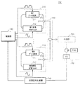
図1は、本発明の一実施形態による光出力装置を示したブロック図である。図1を参照すると、光出力装置100は、第1光生成部110、第2光生成部120、結合部130、及び制御部140から構成される。
FIG. 1 is a block diagram showing an optical output device according to an embodiment of the present invention. Referring to FIG. 1, the
図1に示す光出力装置100は、本実施形態の特徴が不明確になることを防ぐために、本実施形態に関する構成要素のみを図示している。従って、図1に示す構成要素以外に、他の汎用的な構成要素が更に含まれることを、本実施形態に関する技術分野の当業者であれば、理解することができる。
The
第1光生成部110は、第1波長可変光(wavelength−swept light)を生成する。第1光生成部110は、第1ゲイン媒質、第1波長可変フィルタ、及び第1光共振部を含む。図1に示す第1光生成部110は、第1ゲイン媒質、第1波長可変フィルタ、及び第1光共振部を利用して多様に具現される。これに関する具体的な実施形態は、図2〜図6の図面を参照して説明する。但し、図1の第1光生成部110は、図2〜図6の実施形態に限定されるものではない。また、第1光生成部110は、第1ゲイン媒質、第1波長可変フィルタ、及び第1光共振部以外に、光増幅器、バッファ、非線形増幅器(non−linear amplifier)、光分離器(optical isolator)、光結合器(optical coupler)などを更に含む。
The first
第1ゲイン媒質は、第1ゲイン媒質の特性によって決定される所定波長領域内で、光を誘導放出(stimulated emission)し、放出された光を増幅する。本実施形態において、第1ゲイン媒質は、SOA(semiconductor optical amplifier)であり得るが、それに限定されるものではない。 The first gain medium amplifies the emitted light by stimulated emission of light within a predetermined wavelength region determined by the characteristics of the first gain medium. In the present embodiment, the first gain medium may be a SOA (semiconductor optical amplifier), but is not limited thereto.
第1波長可変フィルタは、第1ゲイン媒質によって放出された光の波長をスイーピング(sweeping)して波長可変光を生成する。例えば、第1波長可変フィルタは、ファブリペロー・フィルタ(Fabry−Perot filter)又はポリゴンスキャニング・フィルタ(polygon scanning based filter)であるが、それらに限定されるものではない。 The first wavelength tunable filter sweeps the wavelength of light emitted by the first gain medium to generate wavelength tunable light. For example, the first tunable filter is a Fabry-Perot filter or a polygon scanning based filter, but is not limited thereto.
第1光共振部は、第1ゲイン媒質及び第1波長可変フィルタを利用して生成された波長可変光が所定の出力(power)を有するまで波長可変光を増幅させるために、波長可変光を共振させて移動させる。第1光共振部によって、波長可変光は、第1ゲイン媒質にフィードバックされ、反復して増幅される。例えば、第1光共振部は、少なくとも一つ以上のリングキャビティ(ring cavity)によって構成されるが、それに限定されるものではない。本実施形態によると、第1ゲイン媒質と第1波長可変フィルタは、少なくとも一つ以上のリングキャビティによって構成された第1光共振部に連結される。 The first optical resonator unit amplifies the wavelength tunable light until the wavelength tunable light generated using the first gain medium and the first wavelength tunable filter has a predetermined output (power). Resonate and move. The variable wavelength light is fed back to the first gain medium and repeatedly amplified by the first optical resonator. For example, the first optical resonating unit includes at least one ring cavity, but is not limited thereto. According to the present embodiment, the first gain medium and the first wavelength tunable filter are coupled to the first optical resonator configured by at least one ring cavity.
第2光生成部120は、第2ゲイン媒質、第2波長可変フィルタ、及び第2光共振部を含み、第1波長可変光と異なる中心波長を有する第2波長可変光を生成する。第2光生成部120も、第1光生成部110と同様に、第2ゲイン媒質、第2波長可変フィルタ、及び第2光共振部を利用して多様に具現され、図2〜図6に示す実施形態に限定されるものではない。また、第2光生成部120も、第1光生成部110と同様に、第2ゲイン媒質、第2波長可変フィルタ、及び第2光共振部以外に、光増幅器、バッファ、非線形増幅器、光分離器、光結合器などを更に含む。
The second
第2光生成部120の第2ゲイン媒質、第2波長可変フィルタ、及び第2光共振部は、それぞれ第1光生成部110の第1ゲイン媒質、第1波長可変フィルタ、及び第1光共振部と同様に作動するので、これに関する重複説明を省略する。
The second gain medium, the second wavelength variable filter, and the second optical resonance unit of the second
このとき、第2ゲイン媒質で生成される第2波長可変光の波長領域及び中心波長は、第2ゲイン媒質の特性によって決定される。第2ゲイン媒質に第1ゲイン媒質と異なる特性を有するゲイン媒質を使用することにより、第2ゲイン媒質によって生成される第2波長可変光の中心波長は、第1ゲイン媒質によって生成される第1波長可変光と異なる中心波長を有する。例えば、第1ゲイン媒質として中心波長1.2μmの量子点SOA(semiconductor optical amplifier)を、第2ゲイン媒質として中心波長1.3μmの量子ウェルSOAを使用することができるが、それらに限定されるものではない。 At this time, the wavelength region and the center wavelength of the second variable wavelength light generated by the second gain medium are determined by the characteristics of the second gain medium. By using a gain medium having a characteristic different from that of the first gain medium as the second gain medium, the center wavelength of the second wavelength tunable light generated by the second gain medium is the first gain generated by the first gain medium. It has a central wavelength different from that of the wavelength tunable light. For example, a quantum point SOA (semiconductor optical amplifier) having a center wavelength of 1.2 μm can be used as the first gain medium, and a quantum well SOA having a center wavelength of 1.3 μm can be used as the second gain medium, but the present invention is not limited thereto. It is not a thing.
結合部130は、第1光生成部110で生成された第1波長可変光及び第2光生成部120で生成された第2波長可変光を結合して1つの第3波長可変光を出力する。結合部130は、第1ゲイン媒質によって決定される所定波長領域と、第2ゲイン媒質によって決定される所定波長領域とが合わせられた広帯域の波長可変光を生成する。これによって、光出力装置100は、2以上の波長可変光を結合することで、1つのゲイン媒質を利用して生成することができる光の波長帯域より更に広い波長帯域の光を出力することができる。例えば、結合部130は、光カップラ(coupler)又はWDM(wavelength division multiplexing)技法を利用して具現されるが、それらに限定されるものではない。
The combining
制御部140は、第1光生成部110の第1ゲイン媒質と、第2光生成部120の第2ゲイン媒質とにそれぞれ印加される電流の大きさ及び電流のオン/オフ時点のうちの少なくともいずれか一つを制御することにより、第1波長可変光及び第2波長可変光のそれぞれの出力サイズ(大きさ)と波長領域とを制御する。
The
例えば、制御部140によって、第1ゲイン媒質に印加される電流の大きさを大きくするほど第1波長可変光の出力サイズは大きくなる。また、制御部140で、第1ゲイン媒質に印加される電流を所定時間オフすることにより、電流がオフされた所定時間に対応する特定波長領域の波長可変光を生成しない。これによって、制御部140で、第1ゲイン媒質に印加された電流のオン/オフ時点を制御することで、波長可変光が生成される波長領域を決定することができる。
For example, the output size of the first wavelength variable light increases as the magnitude of the current applied to the first gain medium is increased by the
また、制御部140は、第1波長可変光の光スペクトルの第1波長領域では、波長可変光の出力サイズを小さく制御することができ、第2波長領域では、波長可変光の出力サイズを大きく制御することができる。
In addition, the
本実施形態において、制御部140は、光出力装置100から出力される第3波長可変光のスペクトルがガウス形態(Gaussian shape)を有するように、第1波長可変光及び第2波長可変光のそれぞれの出力サイズと波長領域とを制御することができる。
In the present embodiment, the
他の実施形態において、制御部140は、第1波長可変光の波長領域と、第2波長可変光の波長領域とが重複しないように、第1ゲイン媒質と第2ゲイン媒質とにそれぞれ印加される電流のオン/オフ時点を制御することができる。例えば、制御部140は、第1ゲイン媒質に印加される電流がターンオフされると第2ゲイン媒質に印加される電流がターンオンされるように、第2ゲイン媒質に印加される電流がターンオフされると第1ゲイン媒質に印加される電流がターンオンされるように、電流のオン/オフ時点を制御する。これによって、光出力装置100は、波長可変光のそれぞれの波長領域が重複することにより発生する強度雑音(intensity noise)を除去することができる。
In another embodiment, the
本実施形態による制御部140は、少なくとも一つ以上のプロセッサ(processor)に該当するか、或いは少なくとも一つ以上のプロセッサを含む。また、制御部140は、図1に示すように、光出力装置100の内部に位置してもよいが、それに限定されるものではなく、光出力装置100の外部に位置することもできる。
The
一実施形態によると、光出力装置100は、第1光生成部110及び第2光生成部120以外に、少なくとも一つ以上の光生成部を更に含み得る。これによって、結合部130は、第1波長可変光、第2波長可変光、及び少なくとも一つ以上の光生成部で生成された光を結合して1つの第3波長可変光を出力し、制御部140は、第1波長可変光、第2波長可変光、及び少なくとも一つ以上の光生成部で生成された光のそれぞれの出力サイズと波長領域とを制御する。
According to one embodiment, the
光出力装置100は、制御部140によって、それぞれの出力サイズと波長領域とが制御された第1波長可変光及び第2波長可変光が結合された第3波長可変光を出力する。これによって、光出力装置100は、ガウス形態のスペクトルを有する広い波長領域の波長可変光を生成することができる。また、光出力装置100は、強度雑音が除去され、狭い線幅を有する広い波長領域の波長可変光を生成することができる。
The
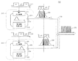
図2は、図1に示す光出力装置の他の実施形態を示した図である。図2を参照すると、光出力装置200は、第1光生成部210、第2光生成部220、及び結合部130から構成される。第1光生成部210は、第1ゲイン媒質211、第1波長可変フィルタ212、第1光共振部213、及び第1カップラ214から構成され、第2光生成部220は、第2ゲイン媒質221、第2波長可変フィルタ222、第2光共振部223、及び第2カップラ224から構成される。
FIG. 2 is a diagram showing another embodiment of the light output device shown in FIG. Referring to FIG. 2, the
図2に示す電流信号241と電流信号242は、それぞれ制御部(図示せず)から、第1ゲイン媒質211と第2ゲイン媒質221とに印加される。本実施形態の特徴について明確に説明するために、図2に示す光出力装置200で、電流信号241と電流信号242とを印加する制御部(図示せず)は、図示していないが、本実施形態に関する技術分野の当業者であれば、図2に示す光出力装置200の内部又は外部に、制御部(図示せず)を更に含むということを理解することができる。
The
第1光生成部210は、第1ゲイン媒質211、第1波長可変フィルタ212、第1光共振部213、及び第1カップラ214を利用して、第1波長可変光を生成する。図2を参照すると、第1ゲイン媒質211、第1波長可変フィルタ212、及び第1カップラ214は、第1光共振部213に直列に連結される。
The first
第1ゲイン媒質211は、第1ゲイン媒質211の特性によって決定される所定波長領域内で光を誘導放出し、放出された光を増幅する。本実施形態による第1ゲイン媒質211は、SOA(semiconductor optical amplifier)であり得るが、それに限定されるものではなく、印加される電流によって放出される光の出力サイズと波長領域とが制御される全てのゲイン媒質を含む。
The
第1波長可変フィルタ212は、第1ゲイン媒質211によって放出された光の波長をスイーピングし、多様な波長を有する波長可変光を生成する。例えば、第1波長可変フィルタ212は、ファブリペロー・フィルタ又はポリゴンスキャニング・フィルタであるが、それらに限定されるものではなく、第1ゲイン媒質211によって放出された光の波長をスイーピングして波長可変光を生成する全ての波長可変フィルタを含む。
The first wavelength
第1光共振部213は、第1ゲイン媒質211及び第1波長可変フィルタ212を利用して生成された波長可変光が所定の出力を有するまで波長可変光を増幅させるために、波長可変光を共振させて移動させる。第1光共振部213によって、波長可変光は、第1ゲイン媒質211にフィードバックされ、フィードバックされた波長可変光は、第1ゲイン媒質211によって更に増幅される。第1光生成部210は、このようなフィードバックと増幅とを反復し、所定の出力を有する第1波長可変光を生成する。本実施形態による第1光共振部213は、少なくとも一つ以上のリングキャビティによって構成される。
The first
第1カップラ214は、第1ゲイン媒質211、第1波長可変フィルタ212、及び第1光共振部213を利用して生成された第1波長可変光の一部を、第2波長可変光と結合するために結合部130に出力し、第1波長可変光の他の一部は、出力を増幅するために、第1光共振部213を介して第1ゲイン媒質211にフィードバックされる。本実施形態による第1カップラ214は、光カップラ又はWDM(wavelength division multiplexing)素子である。
The
電流信号241は、制御部(図示せず)によって第1ゲイン媒質211に印加される。電流信号241が第1ゲイン媒質211に印加されると、第1光生成部210は、電流信号241によって、光の出力サイズと波長領域とが制御された第1波長可変光を生成する。電流信号241がオン状態であるときは、対応する波長領域で第1波長可変光が出力され、電流信号241がオフ状態であるときは、対応する波長領域で第1波長可変光が出力されない。これによって、図2に示す第1波長可変光のスペクトル250が獲得される。図2のスペクトル250を参照すると、電流信号241がオフ状態であるとき、対応する黒色で塗りつぶされた部分の波長帯域では第1波長可変光が出力されない。これによって、制御部(図示せず)から印加される電流信号241のオン/オフ時点を調節することで、第1光生成部210により生成される第1波長可変光の波長領域を決定することができる。
The
また、スペクトル250で、光の出力サイズは、電流信号241の大きさによって決定される。これによって、制御部(図示せず)から印加される電流信号241の大きさを調節することで、第1光生成部210により生成される第1波長可変光の出力サイズを決定することができる。図2に示すスペクトル250は、第1光生成部210によって獲得される光スペクトルの一実施形態に過ぎない。第1光生成部210では、電流信号241の制御によって、図2に示すスペクトル250以外に、多様な形態のスペクトルが獲得される。
In the
第2光生成部220も、第1光生成部210と同様に、第2ゲイン媒質221、第2波長可変フィルタ222、及び第2カップラ224が第2光共振部223に直列に連結される。第2光生成部220の第2ゲイン媒質221、第2波長可変フィルタ222、第2光共振部223、及び第2カップラ224は、第1光生成部210の第1ゲイン媒質211、第1波長可変フィルタ212、第1光共振部213、及び第1カップラ214と同様に作動するので、これに関する重複説明を省略する。
Similarly to the first
第2光生成部220で生成される第2波長可変光の波長領域及び中心波長は、第2ゲイン媒質221の特性によって決定される。第2ゲイン媒質221に、第1ゲイン媒質211と異なる特性を有するゲイン媒質を使用することにより、第2波長可変光の中心波長は、第1光生成部210で生成される第1波長可変光と異なる中心波長を有する。例えば、第1ゲイン媒質211は中心波長1.2μmの量子点SOAであり、第2ゲイン媒質は中心波長1.3μmの量子ウェルSOAであり得るが、それらに限定されるものではない。
The wavelength region and the center wavelength of the second wavelength variable light generated by the second
電流信号242は、制御部(図示せず)によって第2ゲイン媒質221に印加される。第2光生成部220は、電流信号242によって、光の出力サイズと波長領域とが制御された第2波長可変光を生成する。第1波長可変光と同様に、電流信号242がオン状態であるときは対応する波長領域で第2波長可変光が出力され、電流信号242がオフ状態であるときは対応する波長領域で第2波長可変光が出力されない。
The
図2のスペクトル260を参照すると、電流信号242がオフ状態であるとき、対応する黒色で塗りつぶされた部分の波長帯域では第2波長可変光が出力されない。第1波長可変光と同様に、制御部(図示せず)から印加される電流信号242のオン/オフ時点を調節することによって、第2光生成部220によって生成される第2波長可変光の波長領域を決定することができる。また、制御部(図示せず)から印加される電流信号242の大きさを調節することによって、第2波長可変光の出力サイズも決定することができる。図2に示すスペクトル260は、第2光生成部220によって獲得される光スペクトルの一実施形態に過ぎず、スペクトル260以外に、多様な形態のスペクトルが獲得される。
Referring to the
結合部130は、第1光生成部210で生成された第1波長可変光、及び第2光生成部220で生成された第2波長可変光を結合して1つの第3波長可変光を出力する。これによって、図2に示す第3波長可変光のスペクトル270が獲得される。図1で結合部130に関して記載した内容は、図2に示す結合部130にも適用されるので、これに関する重複説明を省略する。
The combining
図2を参照すると、スペクトル270は、電流信号241及び電流信号242がオフ状態であるとき、対応する黒色で塗りつぶされた部分の波長帯域を除外した残りの波長帯域の第1波長可変光と第2波長可変光とが結合されたものであることが分かる。これによって、波長領域が異なる2以上の波長可変光を結合して1つの広帯域波長可変光を生成する際に、波長可変光を生成する光生成部のゲイン媒質のそれぞれに印加される電流のオン/オフ時点を制御することで、波長可変光のそれぞれの波長領域を重複させない。これによって、波長可変光のそれぞれの波長領域が重複することにより発生する強度雑音を除去し、狭い線幅を有する広い波長領域の波長可変光を生成することができる。スペクトル270を参照すると、結合部130から出力される第3波長可変光の帯域幅は、第1光生成部210で生成された第1波長可変光の帯域幅、又は第2光生成部220で生成された第2波長可変の帯域幅よりはるかに広い帯域幅を有する。
Referring to FIG. 2, when the
また、制御部(図示せず)から印加される電流信号241及び電流信号242の電流のオン/オフ時点又は電流の大きさを制御することにより、光出力装置200によって生成される第3波長可変光のスペクトル形態を決定することができる。例えば、光出力装置200は、第3波長可変光のスペクトルがガウス形態を有するように、電流信号241及び電流信号242を制御することができる。図2に示すスペクトル270は、光出力装置200によって獲得される光スペクトルの一実施形態に過ぎない。光出力装置200では、電流信号241及び電流信号242の制御によって、図2に示すスペクトル270以外に、ガウス形態を含む多様な形態のスペクトルが獲得される。
Further, the third wavelength variable generated by the
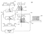
図3は、図1に示す光出力装置の更に他の実施形態を示した図である。図3を参照すると、光出力装置300は、第1光生成部310、第2光生成部320、及び結合部130から構成される。第1光生成部310は、第1ゲイン媒質211、第1波長可変フィルタ212、第1光共振部213、第1カップラ214、及び第1光増幅器315から構成され、第2光生成部320は、第2ゲイン媒質221、第2波長可変フィルタ222、第2光共振部223、第2カップラ224、及び第2光増幅器325から構成される。図3に示す電流信号341と電流信号342は、それぞれ制御部(図示せず)から、第1光増幅器315と第2光増幅器325とに印加される。
FIG. 3 is a view showing still another embodiment of the light output device shown in FIG. Referring to FIG. 3, the
図3に示す第1ゲイン媒質211、第1波長可変フィルタ212、第1光共振部213、第1カップラ214、第2ゲイン媒質221、第2波長可変フィルタ222、第2光共振部223、及び第2カップラ224は、図2に示した第1ゲイン媒質211、第1波長可変フィルタ212、第1光共振部213、第1カップラ214、第2ゲイン媒質221、第2波長可変フィルタ222、第2光共振部223、及び第2カップラ224に対応するので、これに関する重複説明を省略する。
The
本実施形態の特徴について明確に説明するために、図3に示す光出力装置300で、電流信号341と電流信号342とを印加する制御部(図示せず)は、図示していないが、本実施形態に関する技術分野の当業者であれば、図3に示す光出力装置300の内部又は外部に、制御部(図示せず)を更に含むということを理解することができる。
In order to clearly describe the features of the present embodiment, a control unit (not shown) for applying the
第1光増幅器315は、第1ゲイン媒質211、第1波長可変フィルタ212、及び第1光共振部213を利用して生成された波長可変光を増幅する。このとき、第1光増幅器315は、SOA(semiconductor optical amplifier)であり得るが、それに限定されるものではなく、印加される電流によって放出される光の出力サイズと波長領域とが制御される全ての光増幅器を含む。
The first
第1光生成部310は、第1ゲイン媒質211、第1波長可変フィルタ212、及び第1光共振部213を利用して生成された波長可変光を、第1光増幅器315を利用して増幅することにより、第1波長可変光を生成する。
The first
図3を参照すると、第1ゲイン媒質211、第1波長可変フィルタ212、及び第1カップラ214は、第1光共振部213と直列に連結される。第1光増幅器315は、直列に連結された第1ゲイン媒質211、第1波長可変フィルタ212、第1光共振部213、及び第1カップラ214から構成されたループの外部に位置する。これによって、第1光生成部310で、第1ゲイン媒質211、第1波長可変フィルタ212、及び第1光共振部213を利用して生成された波長可変光が、第1ゲイン媒質211にフィードバックされずに、第1カップラ214を介して出力されると、第1光増幅器315によって増幅されて第1波長可変光として出力される。
Referring to FIG. 3, the
図2に示した光出力装置200と異なり、図3の光出力装置300で、電流信号341は、第1光増幅器315に印加される。図3の光出力装置300は、第1ゲイン媒質211ではない第1光増幅器315にそれぞれ印加される電流の大きさ及び電流のオン/オフ時点のうちの少なくともいずれか一つを制御することにより、第1波長可変光の出力サイズと波長領域とを制御する。電流信号341が第1光増幅器315に印加されると、第1光生成部310は、電流信号341によって、光の出力サイズと波長領域とが制御された第1波長可変光を生成する。制御部(図示せず)から印加される電流信号341によって、第1光生成部310により生成された第1波長可変光は、図3に示すスペクトル350のような形態の光スペクトルを有する。図3に示すスペクトル350は、第1光生成部310によって獲得される光スペクトルの一実施形態に過ぎない。
Unlike the
第2光増幅器325は、第2ゲイン媒質221、第2波長可変フィルタ222、及び第2光共振部223を利用して生成された波長可変光を増幅する。このとき、第2光増幅器325は、第1光増幅器315と同様にSOAであり得るが、それに限定されるものではない。
The second
第2光生成部320は、第2ゲイン媒質221、第2波長可変フィルタ222、及び第2光共振部223を利用して生成された波長可変光を、第2光増幅器325を利用して増幅することにより、第2波長可変光を生成する。第2光生成部320は、第1光生成部310で生成された光と異なる中心波長を有する第2波長可変光を生成する。第2光生成部320も、第1光生成部310と同様に、第2ゲイン媒質221、第2波長可変フィルタ222、及び第2カップラ224が第2光共振部223と直列に連結される。第2光増幅器325も、直列に連結された第2ゲイン媒質221、第2波長可変フィルタ222、第2光共振部223、及び第2カップラ224から構成されたループの外部に位置する。
The second
図3の光出力装置300で、電流信号342は、制御部(図示せず)から、第2光増幅器325に印加される。図3の光出力装置300は、第2ゲイン媒質221ではない第2光増幅器325にそれぞれ印加される電流の大きさ及び電流のオン/オフ時点のうちの少なくともいずれか一つを制御することにより、第2波長可変光の出力サイズと波長領域とを制御する。電流信号342が第2光増幅器325に印加されると、第2光生成部320は、電流信号342によって、光の出力サイズと波長領域とが制御された第2波長可変光を生成する。制御部(図示せず)から印加される電流信号342によって、第2光生成部320により生成された第2波長可変光は、図3に示すスペクトル360のような形態の光スペクトルを有する。図3に示すスペクトル360は、第2光生成部320によって獲得される光スペクトルの一実施形態に過ぎない。
In the
結合部130は、第1光生成部310で生成された第1波長可変光、及び第2光生成部320で生成された第2波長可変光を結合して1つの第3波長可変光を出力する。これによって、図3に示す第3波長可変光のスペクトル370が獲得される。図1及び図2で、結合部130に関して記載した内容は、図3に示す結合部130にも適用されるので、これに関する重複説明を省略する。
The combining
図3を参照すると、スペクトル370は、電流信号341及び電流信号342がオフ状態であるとき、対応する黒色で塗りつぶされた部分の波長帯域を除外した残りの波長帯域の第1波長可変光と第2波長可変光とが結合されたものである。これによって、波長可変光を生成する光生成部のゲイン媒質のそれぞれに印加される電流のオン/オフ時点を制御することで、波長可変光のそれぞれの波長領域を重複させない。光出力装置300は、電流信号341及び電流信号342の制御によって、図3に示すスペクトル370以外に、多様な形態のスペクトルを獲得する。例えば、光出力装置300は、電流信号341及び電流信号342の電流のオン/オフ時点及び電流の大きさを制御することにより、第3波長可変光のスペクトルがガウス形態を有するように制御する。
Referring to FIG. 3, when the
制御部(図示せず)は、第1光増幅器315と第2光増幅器325とにそれぞれ印加される電流の大きさ及び電流のオン/オフ時点のうちの少なくともいずれか一つを制御することにより、第1波長可変光及び第2波長可変光のそれぞれの出力サイズと波長領域とを制御する。
The control unit (not shown) controls at least one of the magnitude of the current applied to the first
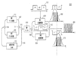
図4は、図1に示す光出力装置の更に他の実施形態を示した図である。図4を参照すると、光出力装置400は、第1光生成部410、第2光生成部420、及び結合部130から構成される。第1光生成部410は、第1ゲイン媒質211、第1波長可変フィルタ212、第1光共振部213、第1カップラ214、第1光増幅器315、及び第1バッファ415から構成され、第2光生成部420は、第2ゲイン媒質221、第2波長可変フィルタ222、第2光共振部223、第2カップラ224、第2光増幅器325、及び第2バッファ425から構成される。図4に示す電流信号441と電流信号442は、それぞれ制御部(図示せず)から、第1光増幅器315と第2光増幅器325とに印加される。
FIG. 4 is a view showing still another embodiment of the light output device shown in FIG. Referring to FIG. 4, the
図4に示す第1ゲイン媒質211、第1波長可変フィルタ212、第1光共振部213、第1カップラ214、第2ゲイン媒質221、第2波長可変フィルタ222、第2光共振部223、及び第2カップラ224は、図2に示した第1ゲイン媒質211、第1波長可変フィルタ212、第1光共振部213、第1カップラ214、第2ゲイン媒質221、第2波長可変フィルタ222、第2光共振部223、及び第2カップラ224に対応するので、これに関する重複説明を省略する。
The
本実施形態の特徴について明確に説明するために、図4に示す光出力装置400で、電流信号441と電流信号442とを印加する制御部(図示せず)は、図示していないが、本実施形態に関する技術分野の当業者であれば、図4に示す光出力装置400の内部又は外部に制御部(図示せず)を更に含むということを理解することができる。
In order to clearly describe the features of this embodiment, a control unit (not shown) that applies the
第1光増幅器315は、第1ゲイン媒質211、第1波長可変フィルタ212、及び第1光共振部213を利用して生成された波長可変光を増幅する。具体的に、第1光増幅器315は、第1ゲイン媒質211、第1波長可変フィルタ212、及び第1光共振部213を利用して生成された波長可変光と、第1バッファ415で保存された少なくとも一つ以上の波長可変光を結合した波長可変光とを増幅する。
The first
第1バッファ415は、第1ゲイン媒質211、第1波長可変フィルタ212、及び第1光共振部213を利用して生成された波長可変光を保存する。第1バッファ415は、光カップラなどを利用して具現される。
The
例えば、第1バッファ415は、第1ゲイン媒質211、第1波長可変フィルタ212、及び第1光共振部213を利用して生成された第4波長可変光を保存する。第1バッファ415は、第4波長可変光が生成された時点から第1時間が経過した後、第1ゲイン媒質211、第1波長可変フィルタ212、及び第1光共振部213を利用して生成された第6波長可変光と、第1バッファ415に保存された第4波長可変光とを結合し、結合された1つの波長可変光を第1光増幅器315に出力する。このとき、第4波長可変光は、第1ゲイン媒質211で生成可能な光の波長領域のうち、第4波長領域で可変された波長を有する光であり、第6波長可変光は、第4波長可変光が生成された時点から第1時間後に生成された波長可変光であり、第4波長領域と異なる第6波長領域で可変された波長を有する光である。
For example, the
これによって、第1光生成部410で、第1ゲイン媒質211、第1波長可変フィルタ212、及び第1光共振部213を利用して生成された第6波長可変光が第1ゲイン媒質211にフィードバックされずに第1カップラ214を介して出力されると、第1光生成部410は、第1バッファ415に保存された第4波長可変光を第6波長可変光に結合し、結合された1つの波長可変光を、第1光増幅器315を利用して増幅することにより、第1波長可変光を生成する。
As a result, the sixth wavelength variable light generated by using the
図4を参照すると、光出力装置400で、第1ゲイン媒質211、第1波長可変フィルタ212、及び第1カップラ214は、第1光共振部213と直列に連結される。第1バッファ415と第1光増幅器315は、直列に連結され、第1バッファ415及び第1光増幅器315は、直列に連結された第1ゲイン媒質211、第1波長可変フィルタ212、第1光共振部213、及び第1カップラ214から構成されたループの外部に位置する。
Referring to FIG. 4, in the
図3に示した光出力装置300と同様に、図4の光出力装置400で、電流信号441は、第1光増幅器315に印加される。これによって、第1光生成部410は、電流信号441により、光の出力サイズと波長領域とが制御された第1波長可変光を生成する。第1波長可変光は、図4に示すスペクトル450のような形態の光スペクトルを有する。図4に示すスペクトル450は、第1光生成部410によって獲得される光スペクトルの一実施形態に過ぎない。
Similar to the
第2光増幅器325は、第2ゲイン媒質221、第2波長可変フィルタ222、及び第2光共振部223を利用して生成された波長可変光を増幅する。具体的に、第2光増幅器325は、第2ゲイン媒質221、第2波長可変フィルタ222、及び第2光共振部223を利用して生成された波長可変光と、第2バッファ425で保存された少なくとも一つ以上の波長可変光とを結合した波長可変光を増幅する。
The second
第2バッファ425は、第2ゲイン媒質221、第2波長可変フィルタ222、及び第2光共振部223を利用して生成された波長可変光を保存する。例えば、第2バッファ425は、光カップラなどを利用して具現される。
The
例えば、第2バッファ425は、第2ゲイン媒質221、第2波長可変フィルタ222、及び第2光共振部223を利用して生成された第5波長可変光を保存する。第2光増幅器325は、第2ゲイン媒質221、第2波長可変フィルタ222、及び第2光共振部223を利用して生成された第7波長可変光と、第2バッファ425で保存された第5波長可変光とを結合した可変光を増幅する。このとき、第5波長可変光は、第2ゲイン媒質221で生成可能な光の波長領域のうち、第5波長領域で可変された波長を有する光であり、第7波長可変光は、第5波長可変光が生成された時点から第2時間後に生成された波長可変光であり、第5波長領域と異なる第7波長領域で可変された波長を有する光である。
For example, the
図4を参照すると、第2光生成部420も、第1光生成部410と同様に、第2ゲイン媒質221、第2波長可変フィルタ222、及び第2カップラ224が第2光共振部223と直列に連結される。第2バッファ425と第2光増幅器325は、直列に連結され、直列に連結された第2ゲイン媒質221、第2波長可変フィルタ222、第2光共振部223、及び第2カップラ224から構成されたループの外部に位置する。
Referring to FIG. 4, similarly to the first
第1光生成部410と同様に、電流信号442は、第2光増幅器325に印加される。これによって、第2光生成部420は、電流信号442により、光の出力サイズと波長領域とが制御された第2波長可変光を生成する。第2波長可変光は、図4に示すスペクトル460のような形態の光スペクトルを有する。図4に示すスペクトル460は、第2光生成部420によって獲得される光スペクトルの一実施形態に過ぎない。
Similar to the first
結合部130は、第1光生成部410で生成された第1波長可変光、及び第2光生成部420で生成された第2波長可変光を結合して1つの第3波長可変光を出力する。これによって、図4に示す第3波長可変光のスペクトル470が獲得される。図1〜図3で、結合部130に関して記載した内容は、図4に示す結合部130にも適用されるので、これに関する重複説明を省略する。
The combining
制御部(図示せず)は、第1光増幅器315と第2光増幅器325とにそれぞれ印加される電流の大きさ及び電流のオン/オフ時点のうちの少なくともいずれか一つを制御することにより、第1波長可変光及び第2波長可変光のそれぞれの出力サイズと波長領域とを制御する。
The control unit (not shown) controls at least one of the magnitude of the current applied to the first
これによって、光出力装置400は、生成された波長可変光をバッファに保存された波長可変光と結合した後、光増幅器の電流制御を利用して波長可変光の波長領域と出力とを制御することにより、生成された波長可変光をバッファに保存された波長可変光と結合する過程で発生するカップリング損失(coupling loss)を補償することができる。
Thus, the
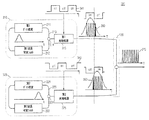
図5は、図1に示す光出力装置の更に他の実施形態を示した図である。図5を参照すると、光出力装置500は、第1ゲイン媒質510、第2ゲイン媒質520、波長可変フィルタ530、第1カップラ541、第1光共振部542、第2カップラ543、第3カップラ544、及び第2光共振部545から構成される。図5に示す電流信号551と電流信号552は、それぞれ制御部(図示せず)から、第1ゲイン媒質510と第2ゲイン媒質520とに印加される。
FIG. 5 is a view showing still another embodiment of the light output device shown in FIG. Referring to FIG. 5, the
本実施形態の特徴について明確に説明するために、光出力装置500で、電流信号551と電流信号552とを印加する制御部(図示せず)は、図示していないが、本実施形態に関する技術分野の当業者であれば、図5に示す光出力装置500の内部又は外部に、制御部(図示せず)を更に含むということを理解することができる。
In order to clearly describe the features of the present embodiment, a control unit (not shown) that applies the
光出力装置500は、第1ゲイン媒質510、波長可変フィルタ530、第1カップラ541、第1光共振部542、第2カップラ543、第3カップラ544、及び第2光共振部545を利用して、第1波長可変光を生成する。このとき、第1波長可変光を生成する光出力装置500の構成要素は、第1光生成部(図示せず)から構成される。
The
光出力装置500は、第2ゲイン媒質520、波長可変フィルタ530、第1カップラ541、第1光共振部542、第2カップラ543、第3カップラ544、及び第2光共振部545を利用して、第2波長可変光を生成する。第2波長可変光を生成する光出力装置500の構成要素は、第2光生成部(図示せず)から構成される。
The
本実施形態によると、第1ゲイン媒質510と第2ゲイン媒質520は、第1光共振部542によって並列に連結される。第1ゲイン媒質510及び第2ゲイン媒質520は、それぞれ波長可変フィルタ530と直列に連結され、第1光共振部542と波長可変フィルタ530は、第2光共振部545と直列に連結される。
According to the present embodiment, the
第1ゲイン媒質510は、光の誘導放出と増幅とを利用して、第1中心波長を有する光を放出する。第2ゲイン媒質520は、光の誘導放出と増幅とを利用して、第1中心波長と異なる第2中心波長を有する光を放出する。例えば、第1ゲイン媒質510と第2ゲイン媒質520は、SOAであり得るが、それに限定されるものではない。
The
波長可変フィルタ530は、第1ゲイン媒質510及び第2ゲイン媒質520で放出された光の波長を可変する。波長可変フィルタ530は、第1ゲイン媒質510又は第2ゲイン媒質520によって放出された光の波長をスイーピングし、多様な波長を有する波長可変光を生成する。例えば、波長可変フィルタ530は、ファブリペロー・フィルタ又はポリゴンスキャニング・フィルタであるが、それらに限定されるものではない。
The wavelength
第1光共振部542は、第1ゲイン媒質510及び第2ゲイン媒質520で放出された光を共振させて移動させる。例えば、第1光共振部542は、少なくとも一つ以上のリングキャビティによって構成される。
The first
第2光共振部545は、波長可変フィルタ530によって可変された波長可変光を、第1ゲイン媒質510及び第2ゲイン媒質520にフィードバックさせる。これによって、第2光共振部545は、第1ゲイン媒質510、第2ゲイン媒質520、及び波長可変フィルタ530を利用して生成された波長可変光が所定の出力を有するまで生成された波長可変光を増幅させる。例えば、第2光共振部545は、少なくとも一つ以上のリングキャビティによって構成される。
The second optical resonating
第1カップラ541は、第1ゲイン媒質510又は第2ゲイン媒質520によって放出された光を、第2光共振部545に出力する。例えば、第1カップラ541は、光カップラである。
The
第2カップラ543は、第1ゲイン媒質510によって生成される第1波長可変光と、第2ゲイン媒質520によって生成される第2波長可変光とを結合し、結合された1つの第3波長可変光を出力する。このとき、第2カップラ543は、図1に示した結合部に該当する。第2カップラ543は、第3波長可変光の一部を光出力装置500から出力し、また第3波長可変光の出力を増幅するために、第2光共振部545を介して、第1ゲイン媒質510又は第2ゲイン媒質520にフィードバックする。例えば、第2カップラ543は、光カップラ又はWDM素子である。
The
第3カップラ544は、波長可変フィルタ530によって可変された波長可変光が、第1ゲイン媒質510又は第2ゲイン媒質520にフィードバックされるように、可変された波長可変光を第1光共振部542に出力する。例えば、第3カップラ544は、光カップラである。
The
制御部(図示せず)は、第1ゲイン媒質510と第2ゲイン媒質520とにそれぞれ印加される電流の大きさ及び電流のオン/オフ時点のうちの少なくともいずれか一つを制御することにより、第1波長可変光及び第2波長可変光のそれぞれの出力サイズと波長領域とを制御する。
The control unit (not shown) controls at least one of the magnitude of the current applied to the
光出力装置500で、電流信号551と電流信号552は、それぞれ第1ゲイン媒質510と第2ゲイン媒質520とに印加される。これによって、光出力装置500は、電流信号551及び電流信号552により、光の出力サイズと波長領域とが制御された第1波長可変光と第2波長可変光とを生成する。例えば、第1波長可変光と第2波長可変光は、それぞれ図5に示すスペクトル560及びスペクトル570のような形態の光スペクトルを有する。光出力装置500は、光の出力サイズと波長領域とが制御された第1波長可変光と第2波長可変光を結合し、スペクトル580のような第3波長可変光の光スペクトルを獲得する。
In the
一実施形態によると、光出力装置500は、光の誘導放出と増幅とを利用して、第1中心波長及び第2中心波長と異なる中心波長を有する光を放出する少なくとも一つ以上のゲイン媒質を更に含み得る。これによって、結合部130は、第1波長可変光、第2波長可変光、及び少なくとも一つ以上のゲイン媒質によって生成される波長可変光を結合して1つの第3波長可変光を出力し、制御部(図示せず)は、第1ゲイン媒質510、第2ゲイン媒質520、及び少なくとも一つ以上のゲイン媒質にそれぞれ印加される電流の大きさ及び電流のオン/オフ時点のうちの少なくともいずれか一つを制御することにより、それぞれの出力サイズと波長領域とが制御された第1波長可変光、第2波長可変光、及び少なくとも一つ以上のゲイン媒質によって生成される波長可変光を結合し、結合された1つの第3波長可変光を出力する。
According to an embodiment, the
図6は、図1に示す光出力装置の更に他の実施形態を示した図である。図6を参照すると、光出力装置600は、第1ゲイン媒質510、第2ゲイン媒質520、波長可変フィルタ530、第1カップラ541、第1光共振部542、第2カップラ543、第3カップラ544、第2光共振部545、第1バッファ610、第1光増幅器620、第2光増幅器630、第4カップラ641、及び第5カップラ642から構成される。図6に示す電流信号651と電流信号652は、それぞれ制御部(図示せず)から、第1光増幅器620と第2光増幅器630とに印加される。
FIG. 6 is a view showing still another embodiment of the light output device shown in FIG. Referring to FIG. 6, the
図6に示す第1ゲイン媒質510、第2ゲイン媒質520、波長可変フィルタ530、第1カップラ541、第1光共振部542、第3カップラ544、第2光共振部545は、図5に示した第1ゲイン媒質510、第2ゲイン媒質520、波長可変フィルタ530、第1カップラ541、第1光共振部542、第3カップラ544、第2光共振部545に対応するので、これに関する重複説明を省略する。
The
本実施形態の特徴について明確に説明するために、光出力装置600で、電流信号651と電流信号652とを印加する制御部(図示せず)は、図示していないが、本実施形態に関する技術分野の当業者であれば、図6に示す光出力装置600の内部又は外部に、制御部(図示せず)を更に含むということを理解することができる。
In order to clearly describe the features of the present embodiment, a control unit (not illustrated) that applies the
第2カップラ543は、第1ゲイン媒質510によって生成される波長可変光と、第2ゲイン媒質520によって生成される波長可変光とを結合し、結合された1つの波長可変光を出力する。第2カップラ543は、結合された1つの波長可変光の一部を光出力装置600から出力し、また結合された1つの波長可変光の出力を増幅するために、第2光共振部545を介して、第1ゲイン媒質510又は第2ゲイン媒質520にフィードバックする。
The
第1バッファ610は、第1ゲイン媒質510及び第2ゲイン媒質520のうちのいずれか1つのゲイン媒質、波長可変フィルタ530、第1光共振部542及び第2光共振部545を利用して生成された波長可変光を保存する。第1バッファ610は、いずれか1つのゲイン媒質、波長可変フィルタ530、第1光共振部542及び第2光共振部545を利用して生成されて保存された波長可変光と異なる波長領域で可変された第4波長可変光を、保存された波長可変光と結合して1つの波長可変光を出力する。
The
第4カップラ641は、第1バッファ610から出力された波長可変光を、第1ゲイン媒質510を利用して生成された波長可変光と、第2ゲイン媒質520を利用して生成された波長可変光とに分け、それぞれ第1光増幅器620と第2光増幅器630とに出力する。第4カップラ641は、光カップラである。
The
第1光増幅器620は、第1バッファ610から出力された波長可変光のうち、第1ゲイン媒質510を利用して生成された波長可変光を増幅することにより、第1波長可変光を生成する。このとき、第1光増幅器620は、SOAであり得るが、それに限定されるものではない。
The first
第2光増幅器630は、第1光増幅器620と並列に連結され、第1バッファ610から出力された波長可変光のうち、第2ゲイン媒質520を利用して生成された波長可変光を増幅することにより、第2波長可変光を生成する。このとき、第2光増幅器325は、第1光増幅器315と同様に、SOAであり得るが、それに限定されるものではない。
The second
第5カップラ642は、第1光増幅器620から出力された第1波長可変光と、第2光増幅器630から出力された第2波長可変光とを結合して1つの第3波長可変光を出力する。このとき、第5カップラ642は、図1に示した結合部に該当する。第5カップラ642は、光カップラ又はWDM素子を利用して具現される。
The
光出力装置600は、第1ゲイン媒質510を利用して生成された波長可変光を、第1バッファ610を利用して結合し、第1光増幅器620を利用して結合された波長可変光を増幅して第1波長可変光を生成する。このとき、第1波長可変光を生成する光出力装置600の構成要素は、第1光生成部(図示せず)から構成される。
The
光出力装置600は、第2ゲイン媒質520を利用して生成された波長可変光を、第1バッファ610を利用して結合し、第2光増幅器630を利用して結合された波長可変光を増幅して第2波長可変光を生成する。第2波長可変光を生成する光出力装置600の構成要素は、第2光生成部(図示せず)から構成される。
The
図6を参照すると、第1ゲイン媒質510と第2ゲイン媒質520は、第1光共振部542によって並列に連結され、第1光共振部542と波長可変フィルタ530は、第2光共振部545と直列に連結され、第1ゲイン媒質510及び第2ゲイン媒質520のそれぞれは、波長可変フィルタ530と直列に連結される。第2光共振部545は、第1バッファ610と直列に連結され、第1バッファ610は、並列に連結された第1光増幅器620及び第2光増幅器630と直列に連結される。
Referring to FIG. 6, the
制御部(図示せず)は、第1光増幅器620及び第2光増幅器630にそれぞれ印加される電流の大きさ及び電流のオン/オフ時点のうちの少なくともいずれか一つを制御することにより、第1波長可変光及び第2波長可変光のそれぞれの出力サイズと波長領域とを制御する。
The controller (not shown) controls at least one of the magnitude of the current applied to the first
光出力装置600で、電流信号651と電流信号652は、それぞれ第1光増幅器620と第2光増幅器630とに印加される。これによって、光出力装置600は、電流信号651及び電流信号652によって、光の出力サイズと波長領域とが制御された第1波長可変光と第2波長可変光とを生成する。例えば、第1波長可変光と第2波長可変光は、それぞれ図6に示すスペクトル660及びスペクトル670のような形態の光スペクトルを有する。光出力装置600は、光の出力サイズと波長領域とが制御された第1波長可変光と第2波長可変光とを結合し、スペクトル680のような第3波長可変光の光スペクトルを獲得する。
In the
図7Aは、本発明の一実施形態による、図1に示す制御部が一つ以上の光生成部の動作を制御する作業を示した図である。図7Aを参照すると、光出力装置700は、第1光生成部210〜第N光生成部710、結合部130、及び制御部140から構成され、光信号抽出部730及び同期信号生成部740を更に含む。
FIG. 7A is a diagram illustrating an operation in which the control unit illustrated in FIG. 1 controls operations of one or more light generation units according to an embodiment of the present invention. Referring to FIG. 7A, the
図7Aに示す光出力装置700は、本実施形態の特徴が不明確になることを防ぐために、本実施形態に関する構成要素のみを図示している。従って、図7Aに示す構成要素以外に、他の汎用的な構成要素が更に含まれるということを、本実施形態に関する技術分野の当業者であれば、理解することができる。図7Aに示す結合部130、制御部140は、図1に示した結合部130、制御部140に対応するので、これに関する重複説明を省略する。
The
第1光生成部210〜第N光生成部710は、第1波長可変光〜第N波長可変光を生成する。図7Aに示す第1光生成部210〜第N光生成部710は、説明の便宜上、図2に示した光生成部の形態で図示しているが、それに限定されるものではなく、図3〜図6に示した光生成部のうちのいずれか1つの形態で具現される。例えば、第1光生成部210〜第N光生成部710は、図3に示した光生成部の形態のように、第1光増幅器(図示せず)〜第N光増幅器(図示せず)を更に含み得る。
The first
結合部130は、第1光生成部210〜第N光生成部710で生成された第1波長可変光〜第N波長可変光を結合し、結合された1つの波長可変光を出力する。
The combining
光信号抽出部730は、第1波長可変光〜第N波長可変光が結合された波長可変光から、所定波長領域の光信号を抽出する。説明の便宜のために、光信号抽出部730は、第1波長可変光〜第N波長可変光が結合された波長可変光から光信号を抽出するものとして図示しているが、それに限定されるものではない。光信号抽出部730は、第1光生成部210〜第N光生成部710のうち、いずれか1つの光生成部によって生成された波長可変光から光信号を抽出することもでき、これに関する一実施形態として、図7Bを参照して後述する。光信号抽出部730は、図7Aに示したように、光ダイオード(PD:photo diode)、光ファイバブラッグ格子(FBG:fiber Bragg grating)、サーキュレータ(circulator)などで具現されるが、それらに限定されるものではなく、光信号抽出部730は、多様な素子で具現される。
The optical
同期信号生成部740は、抽出された光信号に基づいて、第1ゲイン媒質及び第2ゲイン媒質で光を誘導放出して増幅する動作と、第1波長可変フィルタ及び第2波長可変フィルタで光の波長を可変する動作とをそれぞれ同期化するための同期信号を生成する。このとき生成される同期信号は、TTL(transistor−transistor logic)レベルの信号であり得るが、それに限定されるものではない。
The synchronization
制御部140は、第1光生成部210〜第N光生成部710の第1ゲイン媒質211〜第Nゲイン媒質711のそれぞれに印加される電流を制御することにより、第1波長可変光〜第N波長可変光のそれぞれの出力サイズと波長領域とを制御する。本実施形態によって、制御部140は、同期信号に基づいて、第1ゲイン媒質211〜第Nゲイン媒質711のそれぞれに印加される電流と、第1波長可変フィルタ212〜第N波長可変フィルタ712のそれぞれに印加される電圧とを生成することにより、第1ゲイン媒質211〜第Nゲイン媒質711、第1波長可変フィルタ212〜第N波長可変フィルタ712の動作を制御する。
The
他の実施形態において、第1光生成部210〜第N光生成部710が、図3に示した光生成部の形態で具現される場合、制御部140は、同期信号に基づいて、第1光増幅器(図示せず)〜第N光増幅器(図示せず)のそれぞれに印加される電流を更に生成することにより、第1ゲイン媒質211〜第Nゲイン媒質711、第1波長可変フィルタ212〜第N波長可変フィルタ712、第1光増幅器(図示せず)〜第N光増幅器(図示せず)の動作を制御する。
In another embodiment, when the first
光出力装置700は、干渉計720に連結される。これによって、光出力装置700から出力されて結合された波長可変光が干渉計720に入力される。干渉計720は、光出力装置700から出力されて結合された波長可変の光を、測定光と参照光とに分離し、測定光と参照光とが反射して戻ってきた応答光を受信する。例えば、光信号抽出部730は、光出力装置700から出力されて結合された波長可変の光から分離された参照光を照射し、照射された参照光が反射して戻ってきた応答光を受信する干渉計720の参照アーム(reference arm)で光信号を抽出する。なお、参照符号713、714は、それぞれ第N光共振部、第Nカップラである。
図7Bは、本発明の他の実施形態による、図1に示す制御部が一つ以上の光生成部の動作を制御する作業を示した図である。図7Bに示す第1光生成部210〜第N光生成部710、結合部130、制御部140、光信号抽出部730、及び同期信号生成部740は、図7Aに示した第1光生成部210〜第N光生成部710、結合部130、制御部140、光信号抽出部730、及び同期信号生成部740に対応するので、これに関する重複説明を省略する。
FIG. 7B is a diagram illustrating an operation in which the control unit illustrated in FIG. 1 controls operations of one or more light generation units according to another embodiment of the present invention. The first
図7Bの光信号抽出部730は、第1光生成部210で生成された第1波長可変光から光信号を抽出する。このとき、第1光生成部210は、第1波長可変光から光信号を抽出するために、第1光生成部210から第1波長可変光の一部を出力するカップラ735を更に含む。カップラ735によって、第1光生成部210から分離された第1波長可変光の一部は、光信号抽出部730に入力される。図7Aの光信号抽出部730のように、図7Bの光信号抽出部730は、光ダイオード(PD)、光ファイバブラッグ格子(FBG)、サーキュレータなどによって具現されるが、それらに限定されるものではなく、光信号抽出部730は、多様な素子で具現される。
The optical
第1光生成部210で生成された第1波長可変光から光信号を抽出するように、光信号抽出部730は、第2光生成部(図示せず)〜第N光生成部710で生成された第2波長可変光〜第N波長可変光から光信号を抽出することもできる。従って、光信号抽出部730は、第1光生成部210〜第N光生成部710から生成されたいずれか1つの波長可変光及び結合された波長可変光から、所定の波長領域の光信号を抽出することができる。
The optical
図8は、図1に示す光出力装置の更に他の実施形態を示した図である。図8を参照すると、光出力装置800は、第1光生成部810、第2光生成部820、第3光生成部830、第4光生成部840、結合部850、及び非線形光ファイバ増幅器890から構成される。結合部850は、第1カップラ860、第2カップラ870、及び第3カップラ880から構成される。
FIG. 8 is a view showing still another embodiment of the light output device shown in FIG. Referring to FIG. 8, the
本実施形態の特徴について明確に説明するために、図8に示す光出力装置800で、第1光生成部810〜第4光生成部840によって生成された波長可変光の出力サイズと波長領域とを制御する制御部(図示せず)は、図示していないが、本実施形態に関する技術分野の当業者であれば、図8に示す光出力装置800の内部又は外部に、制御部(図示せず)を更に含むということを理解することができる。
In order to clearly describe the characteristics of the present embodiment, the output size and the wavelength region of the tunable light generated by the first
第1光生成部810は、制御部(図示せず)によって、それぞれの出力サイズと波長領域とが制御された第1中心波長λ1を有する第1波長可変光を生成する。
The first
第2光生成部820は、制御部(図示せず)によって、それぞれの出力サイズと波長領域とが制御された第2中心波長λ2を有する第2波長可変光を生成する。
The second
第3光生成部830は、制御部(図示せず)によって、それぞれの出力サイズと波長領域とが制御された、第1波長可変光と波長領域が重複しない第3中心波長λ3を有する第4波長可変光を生成する。
The third
第4光生成部840は、制御部(図示せず)によって、それぞれの出力サイズと波長領域とが制御された、第2波長可変光と波長領域が重複しない第4中心波長λ4を有する第5波長可変光を生成する。
The fourth
第1光生成部810、第2光生成部820、第3光生成部830、及び第4光生成部840は、図2〜図6に示した光生成部のうちのいずれか1つの形態で具現される。例えば、第1光生成部810、第2光生成部820、第3光生成部830、及び第4光生成部840は、図2に示した光生成部のような形態で具現され、制御部(図示せず)は、第1ゲイン媒質(図示せず)〜第4ゲイン媒質(図示せず)にそれぞれ印加される電流の大きさ及び電流のオン/オフ時点を制御することにより、第1波長可変光、第2波長可変光、第4波長可変光、及び5波長可変光のそれぞれの出力サイズと波長領域とを制御する。或いは、第1光生成部810、第2光生成部820、第3光生成部830、及び第4光生成部840は、図3に示した光生成部のような形態で具現され、第1光増幅器(図示せず)〜第4光増幅器(図示せず)にそれぞれ印加される電流の大きさ及び電流のオン/オフ時点を制御することにより、第1波長可変光、第2波長可変光、第4波長可変光、及び5波長可変光のそれぞれの出力サイズと波長領域とを制御することができる。
The first
結合部850は、第1波長可変光、第2波長可変光、第4波長可変光、及び第5波長可変光を結合して1つの第3波長可変光を出力する。これによって、光出力装置800は、第1波長可変光、第2波長可変光、第4波長可変光、及び第5波長可変光のそれぞれの出力サイズと波長領域とが制御されて結合された1つの波長可変光を出力する。
The combining
例えば、結合部850は、第1カップラ860、第2カップラ870、及び第3カップラ880から構成される。このとき、第1カップラ860は、第1波長可変光と第4波長可変光とを結合し、第2カップラ870は、第2波長可変光と第5波長可変光とを結合し、第3カップラ880は、第1波長可変光及び第4波長可変光が結合された波長可変光と、第2波長可変光及び第5波長可変光が結合された波長可変光とを結合して第3波長可変光を出力する。これによって、第1カップラ860により出力される波長可変光は、第1中心波長λ1を有する第1波長可変光と、第3中心波長λ3を有する第4波長可変光とが結合された光であり、図8のスペクトル865のような形態を有する。第2カップラ870によって出力される波長可変光は、第2中心波長λ2を有する第2波長可変光と、第4中心波長λ4を有する第5波長可変光とが結合された光であり、図8のスペクトル875のような形態を有する。第3カップラ880は、スペクトル865の波長可変光と、スペクトル875の波長可変光とを結合し、スペクトル885の形態を有する1つの第3波長可変光を生成する。
For example, the
一実施形態によると、第1カップラ860は、第1波長可変光と第4波長可変光とを、波長分割マルチプレキシング(WDM)方式を利用して結合し、第2カップラ870は、第2波長可変光と第5波長可変光とを、波長分割マルチプレキシング方式を利用して結合する。結合部850は、第1カップラ860及び第2カップラ870を利用して、第1波長可変光及び第4波長可変光を、波長分割マルチプレキシング方式を利用して結合し、第2波長可変光及び第5波長可変光を、波長分割マルチプレキシング方式を利用して結合した後、それぞれ結合された波長可変光を、第3カップラ880を利用して結合する方法以外に、多様な方法でそれぞれの光生成部で生成された波長可変光を結合することができる。
According to an exemplary embodiment, the
非線形光ファイバ増幅器890は、光ファイバの非線形性を利用して、結合部850から出力された波長可変光を増幅する。非線形光ファイバ増幅器890は、それぞれの光生成部で生成された波長可変光を結合部850によって結合する過程で発生する波長可変光の出力損失を補完する。
The nonlinear
図9は、本発明の一実施形態による、図1に示す光出力装置を含む光干渉断層撮影装置(optical coherence tomography apparatus)を示した図である。本実施形態による光干渉断層撮影装置900の光出力装置100は、図1〜図8に示した光出力装置のうちのいずれか一つである。従って、下記で省略した内容であるとしても、図1〜図8に示した光出力装置100について上述した内容は、図9に記載した光出力装置にも適用される。以下では、説明の便宜上、図9の光出力装置100は、図1に示した光出力装置100であると仮定して説明する。
FIG. 9 is a diagram illustrating an optical coherence tomography apparatus including the light output device illustrated in FIG. 1 according to an embodiment of the present invention. The
図9に示す光出力装置100は、本実施形態の特徴が不明確になることを防ぐために、本実施形態に関する構成要素のみを図示している。従って、図9に示す構成要素以外に、他の汎用的な構成要素が更に含まれることを、本実施形態に関する技術分野の当業者であれば、理解することができる。
The
光出力装置100は、第1光生成部で生成される第1波長可変光、及び第2光生成部で生成される第2波長可変光のそれぞれの出力サイズと波長領域とを制御するために、第1光生成部の第1ゲイン媒質と、第2光生成部の第2ゲイン媒質とにそれぞれ印加される電流の大きさ及び電流のオン/オフ時点のうちの少なくともいずれか一つを制御し、第1光生成部で第1ゲイン媒質に印加された電流に基づいて第1中心波長を中心にする第1波長可変の光を生成し、第2光生成部で第2ゲイン媒質に印加された電流に基づいて第2中心波長を中心にする第2波長可変の光を生成し、第1波長可変光及び第2波長可変光を結合して1つの第3波長可変の光を出力する。光出力装置100は、第3波長可変光を干渉計920に伝達する。
The
他の実施形態によると、光出力装置100は、第1光生成部で生成される第1波長可変光、及び第2光生成部で生成される第2波長可変光のそれぞれの出力サイズと波長領域とを制御するために、第1光生成部の第1光増幅器と、第2光生成部の第2光増幅器とにそれぞれ印加される電流の大きさ及び電流のオン/オフ時点のうちの少なくともいずれか一つを制御し、第1波長可変光及び第2波長可変光が結合された第3波長可変の光を出力する。
According to another embodiment, the
干渉計920は、光出力装置100から出力された第3波長可変の光を、測定光及び参照光に分離して測定光を対象体10に照射し、測定光が対象体10から反射して戻ってきた応答光を受信する。
The
干渉計920は、ビームスプリッタ(beam splitter)922及び基準ミラー924を含む。光出力装置100から伝達された第3波長可変光は、ビームスプリッタ922で、測定光及び参照光に分離される。ビームスプリッタ922で分離された光のうちの測定光は、光プローブ930に伝達され、参照光は、基準ミラー924に伝達されて反射した後、再びビームスプリッタ922に戻る。一方、光プローブ930に伝達された測定光は、光プローブ930を介して内部の断層映像を撮影する対象体10に照射され、照射された測定光が対象体10で反射された応答光は、光プローブ930を介してビームスプリッタ922に伝達される。伝達された応答光と、基準ミラー924で反射された参照光は、ビームスプリッタ922で干渉を起こす。
光プローブ930は、コリメータ(collimator)レンズ932、ガルバノスキャナ(galvano scanner)934、及びレンズ936を含む。ここで、ガルバノスキャナ934は、一定軸を中心に一定半径で回転が可能なミラー(mirror)であり、MEMS(micro electro mechanical system)から回転に必要な駆動力を得るMEMSスキャナで具現され得る。干渉計920から伝達された測定光は、光プローブ930のコリメータレンズ932を通過して視準(collimate)され、ガルバノスキャナ934で反射されることによって進行方向が調節され、レンズ936を通過した後、対象体10に照射される。
The
検出器940は、応答光と参照光とによって発生する干渉信号を検出する。検出器940は、検出した干渉信号を映像信号処理器950に伝達する。
The
映像信号処理器950は、干渉信号を利用して、対象体10の断層撮影映像を生成する。映像信号処理器950は、干渉信号を、対象体10の断層映像を示す映像信号に変換する。
The
これによって、光干渉断層撮影装置900は、光出力装置100から出力された広帯域波長可変光を利用して対象体10の断層映像を獲得することにより、軸方向の分解能が向上した高分解能の断層映像を獲得することができる。
As a result, the optical
図10は、本発明の一実施形態による光出力装置が波長可変光を出力する方法を示したフローチャートである。図10を参照すると、図10に記載した方法は、図1〜図9に示した光出力装置で、時系列的に処理される各段階によって構成される。従って、下記で省略する内容であるとしても、図1〜図9に示した光出力装置について上述した内容は、図10に記載する方法にも適用される。 FIG. 10 is a flowchart illustrating a method for outputting a wavelength tunable light by an optical output device according to an embodiment of the present invention. Referring to FIG. 10, the method described in FIG. 10 includes each stage processed in time series in the light output apparatus illustrated in FIGS. 1 to 9. Therefore, even if the contents are omitted below, the contents described above for the optical output device shown in FIGS. 1 to 9 are also applied to the method shown in FIG.
1010段階で、制御部140は、第1光生成部110で生成される第1波長可変光、及び第2光生成部120で生成される第2波長可変光のそれぞれの出力サイズと波長領域とを制御するために、第1光生成部110の第1ゲイン媒質と、第2光生成部120の第2ゲイン媒質とにそれぞれ印加される電流の大きさ及び電流のオン/オフ時点のうちの少なくともいずれか一つを制御する。
In
1020段階で、第1光生成部110で、第1ゲイン媒質に印加された電流に基づいて、第1中心波長を中心にする第1波長可変光を生成する。
In
1030段階で、第2光生成部120で、第2ゲイン媒質に印加された電流に基づいて、第2中心波長を中心にする第2波長可変光を生成する。
In
1040段階で、第1波長可変光及び前記第2波長可変光を結合して1つの第3波長可変の光を出力する。
In
光出力装置100は、波長領域が異なる2以上の波長可変光を結合して1つの広帯域波長可変光を生成する際に、波長可変光を生成する光生成部のゲイン媒質のそれぞれに印加される電流の大きさ及び電流のオン/オフ時点のうちの少なくともいずれか一つを制御することにより、最終的に出力される1つの広帯域波長可変光のスペクトルがガウス形態を有するように、波長可変光のそれぞれの出力サイズと波長領域とを制御することができる。
The
また、光出力装置100は、波長領域が異なる2以上の波長可変光を結合して1つの広帯域波長可変光を生成する際に、波長可変光のそれぞれの波長領域が重複しないように、波長可変光を生成する光生成部のゲイン媒質のそれぞれに印加される電流のオン/オフ時点を制御することにより、波長可変光のそれぞれの波長領域が重複することにより発生する強度雑音を除去することができる。
Further, the
一方、上述の方法は、コンピュータで実行されるプログラムで作成可能であり、コンピュータ読み取り可能な記録媒体を利用して、プログラムを作動させる汎用デジタルコンピュータで具現される。また、上述の方法で使われるデータの構造は、コンピュータ読み取り可能な記録媒体に多くの手段を介して記録される。コンピュータ読み取り可能な記録媒体は、マグネチック記録媒体(例えば、ROM(read−only memory)、フロッピー(登録商標)ディスク、ハードディスクなど)、光学的判読媒体(例えば、CD(compact disc)−ROM、DVD(digital versatile disc)など)のような記録媒体を含む。 On the other hand, the above-described method can be created by a program executed by a computer, and is embodied by a general-purpose digital computer that operates a program using a computer-readable recording medium. The data structure used in the above method is recorded on a computer-readable recording medium through many means. Computer-readable recording media include magnetic recording media (eg, ROM (read-only memory), floppy (registered trademark) disk, hard disk, etc.), optical interpretation media (eg, CD (compact disc) -ROM, DVD, etc.). (Digital versatile disc, etc.).
以上、本発明の実施形態について図面を参照しながら詳細に説明したが、本発明は、上述の実施形態に限定されるものではなく、本発明の技術的範囲から逸脱しない範囲内で多様に変更実施することが可能である。 As mentioned above, although embodiment of this invention was described in detail, referring drawings, this invention is not limited to the above-mentioned embodiment, In the range which does not deviate from the technical scope of this invention, it changes variously. It is possible to implement.
本発明の波長可変光を出力する方法及び光出力装置は、例えば疾病診断関連の技術分野に効果的に適用可能である。 The method and the light output device for outputting wavelength-tunable light of the present invention can be effectively applied to, for example, a technical field related to disease diagnosis.
10 対象体
100、200、300、400、500、600、700、700’、800 光出力装置
110、210、310、410、810 第1光生成部
120、220、320、420、820 第2光生成部
130、850 結合部
140 制御部
211、510 第1ゲイン媒質
212 第1波長可変フィルタ
213、542 第1光共振部
214、541、860 第1カップラ
221、520 第2ゲイン媒質
222 第2波長可変フィルタ
223、545 第2光共振部
224、543、870 第2カップラ
241、242、341、342、441、442、551、552、651、652 電流信号
250、260、270、350、360、370、450、460、470、560、570、580、660、670、680、865、875、885 スペクトル
315、620 第1光増幅器
325、630 第2光増幅器
415、610 第1バッファ
425 第2バッファ
530 波長可変フィルタ
544、880 第3カップラ
641 第4カップラ
642 第5カップラ
710 第N光生成部
711 第Nゲイン媒質
712 第N波長可変フィルタ
713 第N光共振部
714 第Nカップラ
720、920 干渉計
730 光信号抽出部
735 カップラ
740 同期信号生成部
830 第3光生成部
840 第4光生成部
890 非線形光ファイバ増幅器
900 光干渉断層撮影装置
922 ビームスプリッタ
924 基準ミラー
930 光プローブ
932 コリメータレンズ
934 ガルバノスキャナ
936 レンズ
10 Target object 100, 200, 300, 400, 500, 600, 700, 700 ′, 800 Light output device 110, 210, 310, 410, 810 First light generation unit 120, 220, 320, 420, 820 Second light Generation unit 130, 850 Coupling unit 140 Control unit 211, 510 First gain medium 212 First wavelength variable filter 213, 542 First optical resonator 214, 541, 860 First coupler 221, 520 Second gain medium 222 Second wavelength Variable filter 223, 545 Second optical resonator 224, 543, 870 Second coupler 241, 242, 341, 342, 441, 442, 551, 552, 651, 652 Current signal 250, 260, 270, 350, 360, 370 450, 460, 470, 560, 570, 580, 660, 670 , 680, 865, 875, 885 Spectrum 315, 620 First optical amplifier 325, 630 Second optical amplifier 415, 610 First buffer 425 Second buffer 530 Tunable filter 544, 880 Third coupler 641 Fourth coupler 642 Fifth Coupler 710 Nth light generation unit 711 Nth gain medium 712 Nth wavelength tunable filter 713 Nth optical resonance unit 714 Nth coupler 720, 920 Interferometer 730 Optical signal extraction unit 735 Coupler 740 Synchronization signal generation unit 830 Third light generation Unit 840 fourth light generation unit 890 nonlinear optical fiber amplifier 900 optical coherence tomography apparatus 922 beam splitter 924 reference mirror 930 optical probe 932 collimator lens 934 galvano scanner 936 lens
Claims (24)
第1ゲイン媒質、第1波長可変フィルタ、及び第1光共振部を含み、第1波長可変光を生成する第1光生成部と、
第2ゲイン媒質、第2波長可変フィルタ、及び第2光共振部を含み、前記第1波長可変光と異なる中心波長を有する第2波長可変光を生成する第2光生成部と、
前記第1波長可変光及び前記第2波長可変光を結合して1つの第3波長可変光を出力する結合部と、
前記第1ゲイン媒質と前記第2ゲイン媒質とにそれぞれ印加される電流の大きさ及び電流のオン/オフ時点のうちの少なくともいずれか一つを制御することにより、前記第1波長可変光及び前記第2波長可変光のそれぞれの出力サイズと波長領域とを制御する制御部と、を備えることを特徴とする光出力装置。 An optical output device for irradiating wavelength-tunable light,
A first light generation unit that includes a first gain medium, a first wavelength tunable filter, and a first optical resonator, and generates first wavelength tunable light;
A second light generating unit including a second gain medium, a second wavelength tunable filter, and a second optical resonator, and generating a second wavelength tunable light having a central wavelength different from the first wavelength tunable light;
A coupling unit that couples the first wavelength tunable light and the second wavelength tunable light to output one third wavelength tunable light;
By controlling at least one of the magnitude of the current applied to each of the first gain medium and the second gain medium and the on / off time of the current, the first wavelength tunable light and the An optical output device comprising: a control unit that controls each output size and wavelength region of the second wavelength variable light.
前記抽出された光信号に基づいて、前記第1光生成部及び前記第2光生成部のそれぞれで、ゲイン媒質の光を誘導放出して増幅する動作と波長可変フィルタの光の波長を可変する動作とを同期化するための同期信号を生成する同期信号生成部と、を更に含み、
前記制御部は、前記同期信号に基づいて、前記第1ゲイン媒質及び第2ゲイン媒質のそれぞれに印加される電流と前記第1波長可変フィルタ及び前記第2波長可変フィルタのそれぞれに印加される電圧とを生成することにより、前記第1ゲイン媒質、前記第2ゲイン媒質、前記第1波長可変フィルタ、及び前記第2波長可変フィルタを制御することを特徴とする請求項1に記載の光出力装置。 An optical signal extraction unit that extracts an optical signal in a predetermined wavelength region of any one of the first wavelength variable light and the second wavelength variable light;
Based on the extracted optical signal, each of the first light generation unit and the second light generation unit varies the operation of amplifying and amplifying the light of the gain medium and the wavelength of the light of the wavelength tunable filter. A synchronization signal generator for generating a synchronization signal for synchronizing the operation,
The controller is configured to apply a current applied to each of the first gain medium and the second gain medium and a voltage applied to each of the first wavelength tunable filter and the second wavelength tunable filter based on the synchronization signal. 2. The light output device according to claim 1, wherein the first gain medium, the second gain medium, the first wavelength tunable filter, and the second wavelength tunable filter are controlled by generating .
前記光信号抽出部は、前記干渉計の参照アームで、前記第3波長可変光の所定波長領域の光信号を抽出することを特徴とする請求項5に記載の光出力装置。 The optical output device outputs the third wavelength variable light to an interferometer;
The optical output device according to claim 5, wherein the optical signal extraction unit extracts an optical signal in a predetermined wavelength region of the third wavelength variable light with a reference arm of the interferometer.
前記第2波長可変光と波長領域が重複しない第5波長可変光を生成する第4光生成部と、を更に含み、
前記結合部は、前記第1波長可変光、前記第2波長可変光、前記第4波長可変光、及び前記第5波長可変光を結合して1つの第3波長可変光を出力し、
前記制御部は、前記第1波長可変光、前記第2波長可変光、前記第4波長可変光、及び前記第5波長可変光のそれぞれの出力サイズと波長領域とを制御することを特徴とする請求項1に記載の光出力装置。 A third light generation unit that generates a fourth wavelength variable light that does not overlap a wavelength region with the first wavelength variable light;
A fourth light generation unit for generating a fifth wavelength variable light having a wavelength region that does not overlap with the second wavelength variable light;
The coupling unit combines the first wavelength variable light, the second wavelength variable light, the fourth wavelength variable light, and the fifth wavelength variable light to output one third wavelength variable light,
The control unit controls output sizes and wavelength regions of the first wavelength tunable light, the second wavelength tunable light, the fourth wavelength tunable light, and the fifth wavelength tunable light. The light output device according to claim 1.
前記結合部は、前記第1波長可変光、前記第2波長可変光、及び前記少なくとも一つ以上の光生成部で生成された光を結合して1つの第3波長可変光を出力し、
前記制御部は、前記第1波長可変光、前記第2波長可変光、及び前記少なくとも一つ以上の光生成部で生成された光のそれぞれの出力サイズと波長領域とを制御することを特徴とする請求項1に記載の光出力装置。 And further comprising at least one light generating unit,
The coupling unit combines the first wavelength tunable light, the second wavelength tunable light, and the light generated by the at least one light generation unit to output one third wavelength tunable light,
The control unit controls an output size and a wavelength region of each of the first wavelength variable light, the second wavelength variable light, and the light generated by the at least one light generation unit. The light output device according to claim 1.
第1ゲイン媒質、第1波長可変フィルタ、第1光共振部、及び第1光増幅器を含み、第1波長可変光を生成する第1光生成部と、
第2ゲイン媒質、第2波長可変フィルタ、第2光共振部、及び第2光増幅器を含み、前記第1波長可変光と異なる中心波長を有する第2波長可変光を生成する第2光生成部と、
前記第1波長可変光及び前記第2波長可変光を結合して1つの第3波長可変光を出力する結合部と、
前記第1光増幅器と前記第2光増幅器とにそれぞれ印加される電流の大きさ及び電流のオン/オフ時点のうちの少なくともいずれか一つを制御することにより、前記第1波長可変光及び前記第2波長可変光のそれぞれの出力サイズと波長領域とを制御する制御部と、を備え、
前記第1光生成部は、前記第1ゲイン媒質、前記第1波長可変フィルタ、及び前記第1光共振部を利用して生成された波長可変光を、前記第1光増幅器を利用して増幅することにより前記第1波長可変光を生成し、
前記第2光生成部は、前記第2ゲイン媒質、前記第2波長可変フィルタ、及び前記第2光共振部を利用して生成された波長可変光を、前記第2光増幅器を利用して増幅することにより前記第2波長可変光を生成することを特徴とする光出力装置。 An optical output device that outputs wavelength tunable light,
A first light generation unit including a first gain medium, a first wavelength tunable filter, a first optical resonance unit, and a first optical amplifier, and generating first wavelength tunable light;
A second light generation unit that includes a second gain medium, a second wavelength variable filter, a second optical resonator, and a second optical amplifier, and generates a second wavelength variable light having a central wavelength different from that of the first wavelength variable light. When,
A coupling unit that couples the first wavelength tunable light and the second wavelength tunable light to output one third wavelength tunable light;
By controlling at least one of the magnitude of the current applied to each of the first optical amplifier and the second optical amplifier and the on / off time of the current, the first wavelength tunable light and the A control unit for controlling each output size and wavelength region of the second wavelength variable light,
The first light generation unit amplifies the tunable light generated using the first gain medium, the first tunable filter, and the first optical resonance unit using the first optical amplifier. To generate the first wavelength tunable light,
The second light generation unit amplifies the wavelength tunable light generated using the second gain medium, the second wavelength tunable filter, and the second optical resonance unit using the second optical amplifier. And generating the second wavelength tunable light.
前記第2光生成部は、前記第2ゲイン媒質、前記第2波長可変フィルタ、及び前記第2光共振部を利用して生成された波長可変光を保存する第2バッファを更に含み、
前記第1光生成部は、前記第1バッファに保存された波長可変光と異なる波長領域で可変された第4波長可変光を生成し、該第4波長可変光と前記第1バッファに保存された波長可変光を結合した1つの波長可変光とを、前記第1光増幅器を利用して増幅することにより前記第1波長可変光を生成し、
前記第2光生成部は、前記第2バッファに保存された波長可変光と異なる波長領域で可変された第5波長可変光を生成し、該第5波長可変光と前記第2バッファに保存された波長可変光を結合した1つの波長可変光とを、前記第2光増幅器を利用して増幅することにより前記第2波長可変光を生成することを特徴とする請求項11に記載の光出力装置。 The first light generation unit further includes a first buffer that stores the wavelength variable light generated using the first gain medium, the first wavelength tunable filter, and the first optical resonance unit,
The second light generation unit further includes a second buffer that stores the wavelength variable light generated using the second gain medium, the second wavelength variable filter, and the second optical resonance unit,
The first light generation unit generates a fourth wavelength tunable light that is tunable in a wavelength region different from the wavelength tunable light stored in the first buffer, and is stored in the fourth wavelength tunable light and the first buffer. Generating the first wavelength tunable light by amplifying the wavelength tunable light combined with the wavelength tunable light using the first optical amplifier,
The second light generation unit generates fifth tunable light that is tunable in a wavelength region different from the tunable light stored in the second buffer, and is stored in the fifth tunable light and the second buffer. 12. The optical output according to claim 11, wherein the second tunable light is generated by amplifying one tunable light combined with the tunable light using the second optical amplifier. apparatus.
前記結合部は、前記第1波長可変光、前記第2波長可変光、及び前記少なくとも一つ以上の光生成部で生成された光を結合して1つの第3波長可変光を出力し、
前記制御部は、前記第1光増幅器、前記第2光増幅器、及び前記少なくとも一つ以上の光生成部の光増幅器にそれぞれ印加される電流の大きさ及び電流のオン/オフ時点のうちの少なくともいずれか一つを制御することにより、前記第1波長可変光、前記第2波長可変光、及び前記少なくとも一つ以上の光生成部で生成された光のそれぞれの出力サイズと波長領域とを制御することを特徴とする請求項11に記載の光出力装置。 It further includes at least one light generation unit including a gain medium, a wavelength tunable filter, an optical resonance unit, and an optical amplifier,
The coupling unit combines the first wavelength tunable light, the second wavelength tunable light, and the light generated by the at least one light generation unit to output one third wavelength tunable light,
The control unit includes at least one of a magnitude of a current applied to the first optical amplifier, the second optical amplifier, and the optical amplifiers of the at least one light generation unit, and a current on / off time point. By controlling any one of them, the output size and wavelength region of each of the first wavelength tunable light, the second wavelength tunable light, and the light generated by the at least one light generation unit are controlled. The light output device according to claim 11, wherein:
光の誘導放出と増幅とを利用して第1中心波長を有する光を放出する第1ゲイン媒質と、
光の誘導放出と増幅とを利用して前記第1中心波長と異なる第2中心波長を有する光を放出する第2ゲイン媒質と、
前記第1ゲイン媒質及び前記第2ゲイン媒質を並列に連結して前記第1ゲイン媒質及び前記第2ゲイン媒質で放出された光を共振させて移動させる第1光共振部と、
前記第1ゲイン媒質及び前記第2ゲイン媒質で放出された光の波長を可変する波長可変フィルタと、
前記第1光共振部と前記波長可変フィルタとを直列に連結し、前記波長可変フィルタによって可変された波長可変光を前記第1ゲイン媒質及び前記第2ゲイン媒質にフィードバックさせる第2光共振部と、
前記第1ゲイン媒質によって生成される第1波長可変光と前記第2ゲイン媒質によって生成される第2波長可変光とが結合された1つの第3波長可変光を出力する結合部と、
前記第1ゲイン媒質と前記第2ゲイン媒質とにそれぞれ印加される電流の大きさ及び電流のオン/オフ時点のうちの少なくともいずれか一つを制御することにより、前記第1波長可変光及び前記第2波長可変光のそれぞれの出力サイズと波長領域とを制御する制御部と、を備えることを特徴とする光出力装置。 An optical output device that outputs wavelength tunable light,
A first gain medium that emits light having a first central wavelength utilizing stimulated emission and amplification of light;
A second gain medium that emits light having a second center wavelength different from the first center wavelength using stimulated emission and amplification of light;
A first optical resonator that connects the first gain medium and the second gain medium in parallel to resonate and move the light emitted from the first gain medium and the second gain medium;
A wavelength tunable filter that varies the wavelength of light emitted from the first gain medium and the second gain medium;
A second optical resonator that connects the first optical resonator and the wavelength tunable filter in series, and feeds back the wavelength tunable light that has been changed by the wavelength tunable filter to the first gain medium and the second gain medium; ,
A coupling unit that outputs one third wavelength variable light in which the first wavelength variable light generated by the first gain medium and the second wavelength variable light generated by the second gain medium are combined;
By controlling at least one of the magnitude of the current applied to each of the first gain medium and the second gain medium and the on / off time of the current, the first wavelength tunable light and the An optical output device comprising: a control unit that controls each output size and wavelength region of the second wavelength variable light.
前記結合部は、前記第1波長可変光、前記第2波長可変光、及び前記少なくとも一つ以上のゲイン媒質によって生成される波長可変光が結合された1つの第3波長可変光を出力し、
前記制御部は、前記第1ゲイン媒質、前記第2ゲイン媒質、及び前記少なくとも一つ以上のゲイン媒質にそれぞれ印加される電流の大きさ及び電流のオン/オフ時点のうちの少なくともいずれか一つを制御することにより、前記第1波長可変光、前記第2波長可変光、及び前記少なくとも一つ以上のゲイン媒質によって生成される波長可変光のそれぞれの出力サイズと波長領域とを制御することを特徴とする請求項14に記載の光出力装置。 Using at least one gain medium that emits light having a central wavelength different from the first central wavelength and the second central wavelength by utilizing stimulated emission and amplification of light;
The coupling unit outputs one third wavelength variable light in which the first wavelength variable light, the second wavelength variable light, and the wavelength variable light generated by the at least one gain medium are combined,
The control unit includes at least one of a magnitude of a current applied to the first gain medium, the second gain medium, and the at least one gain medium, and a current on / off time point. Controlling the output size and wavelength region of each of the first wavelength tunable light, the second wavelength tunable light, and the wavelength tunable light generated by the at least one gain medium. The light output device according to claim 14, wherein the light output device is a light output device.
光の誘導放出と増幅とを利用して第1中心波長を有する光を放出する第1ゲイン媒質と、
光の誘導放出と増幅とを利用して前記第1中心波長と異なる第2中心波長を有する光を放出する第2ゲイン媒質と、
前記第1ゲイン媒質及び前記第2ゲイン媒質を並列に連結して前記第1ゲイン媒質及び前記第2ゲイン媒質で放出された光を共振させて移動させる第1光共振部と、
前記第1ゲイン媒質及び前記第2ゲイン媒質で放出された光の波長を可変する波長可変フィルタと、
前記第1光共振部と前記波長可変フィルタとを直列に連結し、前記波長可変フィルタによって可変された波長可変光を前記第1ゲイン媒質及び前記第2ゲイン媒質にフィードバックさせる第2光共振部と、
前記第1ゲイン媒質又は前記第2ゲイン媒質のうちのいずれか1つのゲイン媒質と前記波長可変フィルタと前記第1光共振部及び前記第2光共振部とを利用して生成された波長可変光を保存し、前記いずれか1つのゲイン媒質と前記波長可変フィルタと前記第1光共振部及び前記第2光共振部とを利用して生成されて保存された前記波長可変光と異なる波長領域で可変された第4波長可変光と前記保存された波長可変光とを結合して1つの波長可変光を出力する第1バッファと、
前記第1バッファから出力された波長可変光のうちの前記第1ゲイン媒質を利用して生成された波長可変光を増幅することにより第1波長可変光を生成する第1光増幅器と、
前記第1光増幅器と並列に連結され、前記第1バッファから出力された波長可変光のうちの前記第2ゲイン媒質を利用して生成された波長可変光を増幅することにより第2波長可変光を生成する第2光増幅器と、
前記第1波長可変光と前記第2波長可変光とを結合して1つの第3波長可変光を出力する結合部と、
前記第1光増幅器と前記第2光増幅器とにそれぞれ印加される電流の大きさ及び電流のオン/オフ時点のうちの少なくともいずれか一つを制御することにより、前記第1波長可変光及び前記第2波長可変光のそれぞれの出力サイズと波長領域とを制御する制御部と、を備えることを特徴とする光出力装置。 An optical output device that outputs wavelength tunable light,
A first gain medium that emits light having a first central wavelength utilizing stimulated emission and amplification of light;
A second gain medium that emits light having a second center wavelength different from the first center wavelength using stimulated emission and amplification of light;
A first optical resonator that connects the first gain medium and the second gain medium in parallel to resonate and move the light emitted from the first gain medium and the second gain medium;
A wavelength tunable filter that varies the wavelength of light emitted from the first gain medium and the second gain medium;
A second optical resonator that connects the first optical resonator and the wavelength tunable filter in series, and feeds back the wavelength tunable light that has been changed by the wavelength tunable filter to the first gain medium and the second gain medium; ,
Wavelength tunable light generated using any one of the first gain medium or the second gain medium, the wavelength tunable filter, the first optical resonator, and the second optical resonator. In a wavelength region different from the wavelength tunable light generated and stored using any one of the gain medium, the wavelength tunable filter, the first optical resonator, and the second optical resonator. A first buffer that combines the variable fourth wavelength variable light and the stored wavelength variable light to output one wavelength variable light;
A first optical amplifier that generates a first wavelength variable light by amplifying the wavelength variable light generated using the first gain medium of the wavelength variable light output from the first buffer;
The second wavelength tunable light, which is coupled in parallel with the first optical amplifier and amplifies the wavelength tunable light generated using the second gain medium among the wavelength tunable light output from the first buffer. A second optical amplifier for generating
A coupling unit that couples the first wavelength tunable light and the second wavelength tunable light to output one third wavelength tunable light;
By controlling at least one of the magnitude of the current applied to each of the first optical amplifier and the second optical amplifier and the on / off time of the current, the first wavelength tunable light and the An optical output device comprising: a control unit that controls each output size and wavelength region of the second wavelength variable light.
第1光生成部で生成される第1波長可変光及び第2光生成部で生成される第2波長可変光のそれぞれの出力サイズと波長領域とを制御するために、前記第1光生成部の第1ゲイン媒質と前記第2光生成部の第2ゲイン媒質とにそれぞれ印加される電流の大きさ及び電流のオン/オフ時点のうちの少なくともいずれか一つを制御する段階と、
前記第1光生成部で前記第1ゲイン媒質に印加された電流に基づいて第1中心波長を中心にする第1波長可変光を生成する段階と、
前記第2光生成部で前記第2ゲイン媒質に印加された電流に基づいて第2中心波長を中心にする第2波長可変光を生成する段階と、
前記第1波長可変光及び前記第2波長可変光を結合して1つの第3波長可変光を出力する段階と、を有することを特徴とする光出力方法。 A method of outputting wavelength tunable light,
In order to control each output size and wavelength region of the first wavelength variable light generated by the first light generation unit and the second wavelength variable light generated by the second light generation unit, the first light generation unit Controlling at least one of the magnitude of the current applied to each of the first gain medium and the second gain medium of the second light generation unit and the current on / off timing;
Generating a first wavelength tunable light centered on a first center wavelength based on a current applied to the first gain medium in the first light generation unit;
Generating second tunable light centered on a second central wavelength based on a current applied to the second gain medium in the second light generation unit;
Combining the first wavelength variable light and the second wavelength variable light to output one third wavelength variable light.
前記抽出された光信号に基づいて、前記第1光生成部及び前記第2光生成部のそれぞれで、ゲイン媒質の光を誘導放出して増幅する動作と波長可変フィルタの光の波長を可変する動作とを同期化するための同期信号を生成する段階と、を更に含み、
前記制御する段階は、前記同期信号に基づいて、前記第1ゲイン媒質及び第2ゲイン媒質のそれぞれに印加される電流と前記第1波長可変フィルタ及び前記第2波長可変フィルタのそれぞれに印加される電圧とを生成することにより、前記第1ゲイン媒質、前記第2ゲイン媒質、前記第1波長可変フィルタ、及び前記第2波長可変フィルタの動作を制御することを特徴とする請求項17に記載の光出力方法。 Extracting an optical signal in a predetermined wavelength region of any one of the first wavelength variable light, the second wavelength variable light, and the third wavelength variable light;
Based on the extracted optical signal, each of the first light generation unit and the second light generation unit varies the operation of amplifying and amplifying the light of the gain medium and the wavelength of the light of the wavelength tunable filter. Generating a synchronization signal to synchronize operation; and
The controlling step is applied to each of the first gain medium and the second gain medium and to each of the first wavelength tunable filter and the second wavelength tunable filter based on the synchronization signal. 18. The operation of the first gain medium, the second gain medium, the first wavelength tunable filter, and the second wavelength tunable filter is controlled by generating a voltage. Light output method.
第1光生成部で生成される第1波長可変光及び第2光生成部で生成される第2波長可変光のそれぞれの出力サイズと波長領域とを制御するために、前記第1光生成部の第1ゲイン媒質と前記第2光生成部の第2ゲイン媒質とにそれぞれ印加される電流の大きさ及び電流のオン/オフ時点のうちの少なくともいずれか一つを制御し、前記第1光生成部で前記第1ゲイン媒質に印加された電流に基づいて第1中心波長を中心にする第1波長可変光を生成し、前記第2光生成部で前記第2ゲイン媒質に印加された電流に基づいて第2中心波長を中心にする第2波長可変光を生成し、前記第1波長可変光及び前記第2波長可変光を結合して1つの第3波長可変光を出力する光出力装置と、
前記出力された第3波長可変光を測定光及び参照光に分離し、前記測定光を対象体に照射して前記測定光が対象体で反射して戻ってきた応答光を受信する干渉計と、
前記応答光と前記参照光とによって発生する干渉信号を検出する検出器と、
前記検出された干渉信号を利用して前記対象体の断層撮影映像を生成する映像信号処理器と、を備えることを特徴とする光干渉断層撮影装置。 An optical coherence tomography apparatus that images a tomography by irradiating a target with light,
In order to control each output size and wavelength region of the first wavelength variable light generated by the first light generation unit and the second wavelength variable light generated by the second light generation unit, the first light generation unit Controlling at least one of the magnitude of the current applied to the first gain medium and the second gain medium of the second light generation unit and the on / off time of the current, respectively. Based on the current applied to the first gain medium by the generation unit, the first wavelength variable light centered on the first central wavelength is generated, and the current applied to the second gain medium by the second light generation unit Output device for generating a second wavelength tunable light having a second center wavelength as a center based on the first wavelength variable light and combining the first wavelength tunable light and the second wavelength tunable light to output one third wavelength tunable light When,
An interferometer that separates the output third wavelength variable light into measurement light and reference light, irradiates the measurement light onto the object, and receives response light returned by the measurement light reflected by the object; ,
A detector for detecting an interference signal generated by the response light and the reference light;
An optical coherence tomography apparatus comprising: an image signal processor that generates a tomography image of the object using the detected interference signal.
Applications Claiming Priority (4)
| Application Number | Priority Date | Filing Date | Title |
|---|---|---|---|
| US201261646464P | 2012-05-14 | 2012-05-14 | |
| US61/646,464 | 2012-05-14 | ||
| KR1020120139829A KR20130127355A (en) | 2012-05-14 | 2012-12-04 | Apparatus and method for emitting wavelength-swept light |
| KR10-2012-0139829 | 2012-12-04 |
Publications (1)
| Publication Number | Publication Date |
|---|---|
| JP2013239710A true JP2013239710A (en) | 2013-11-28 |
Family
ID=48537762
Family Applications (1)
| Application Number | Title | Priority Date | Filing Date |
|---|---|---|---|
| JP2013101981A Pending JP2013239710A (en) | 2012-05-14 | 2013-05-14 | Method of outputting variable wavelength light and light output device, optical interference tomographic device, and computer readable recording medium |
Country Status (4)
| Country | Link |
|---|---|
| US (1) | US9739593B2 (en) |
| EP (1) | EP2665142A3 (en) |
| JP (1) | JP2013239710A (en) |
| CN (1) | CN103427334B (en) |
Cited By (1)
| Publication number | Priority date | Publication date | Assignee | Title |
|---|---|---|---|---|
| JP2016219712A (en) * | 2015-05-25 | 2016-12-22 | 株式会社メガオプト | Multiwavelength laser oscillation device and multiwavelength laser oscillation method |
Families Citing this family (4)
| Publication number | Priority date | Publication date | Assignee | Title |
|---|---|---|---|---|
| CN109520972A (en) * | 2018-12-04 | 2019-03-26 | 青岛理工大学 | A kind of stagewise visibility measurement method and device |
| KR102583109B1 (en) * | 2019-02-20 | 2023-09-27 | 삼성전자주식회사 | Display panel and driving method of the display panel |
| KR102168373B1 (en) * | 2019-05-24 | 2020-10-22 | 세종대학교산학협력단 | Wireless optical charging system and method |
| CN117119643B (en) * | 2023-10-20 | 2024-04-02 | 光越科技(深圳)有限公司 | Sweep frequency light source and sweep frequency optical coherence tomography system |
Family Cites Families (30)
| Publication number | Priority date | Publication date | Assignee | Title |
|---|---|---|---|---|
| US7190705B2 (en) | 2000-05-23 | 2007-03-13 | Imra America. Inc. | Pulsed laser sources |
| US6665320B1 (en) * | 2001-01-29 | 2003-12-16 | Lightwave Electronics | Wideband tunable laser sources with multiple gain elements |
| EP2293031B8 (en) | 2003-10-27 | 2024-03-20 | The General Hospital Corporation | Method and apparatus for performing optical imaging using frequency-domain interferometry |
| EP2838167A1 (en) * | 2005-01-20 | 2015-02-18 | Massachusetts Institute of Technology | Mode locking methods and apparatus |
| US8120778B2 (en) * | 2009-03-06 | 2012-02-21 | Imra America, Inc. | Optical scanning and imaging systems based on dual pulsed laser systems |
| JP4869896B2 (en) * | 2006-12-07 | 2012-02-08 | 富士フイルム株式会社 | Optical tomographic imaging system |
| JP5541831B2 (en) * | 2006-12-07 | 2014-07-09 | 株式会社トプコン | Optical tomographic imaging apparatus and operating method thereof |
| CN105581776B (en) | 2007-01-10 | 2018-10-16 | 光学实验室成像公司 | Device and method and linearisation tunable optic filter for tunable optic filter linearisation |
| JP2009031238A (en) | 2007-06-29 | 2009-02-12 | Optical Comb Inc | Optical coherence tomography device |
| JP2009252813A (en) | 2008-04-02 | 2009-10-29 | Fujifilm Corp | Light source, and optical tomography imaging apparatus |
| KR101011562B1 (en) | 2008-05-07 | 2011-01-27 | 경북대학교 산학협력단 | Wavelength Tunable Ring Laser |
| KR100978191B1 (en) | 2008-05-07 | 2010-08-25 | 경북대학교 산학협력단 | Multi-light source switching Laser |
| KR101011623B1 (en) | 2008-05-07 | 2011-01-28 | 경북대학교 산학협력단 | Frequency Swept Laser using a rotating slit |
| JP5361243B2 (en) | 2008-05-13 | 2013-12-04 | キヤノン株式会社 | Optical tomographic imaging system |
| JP2010005266A (en) | 2008-06-30 | 2010-01-14 | Fujifilm Corp | Optical coherence tomography system |
| JP5306075B2 (en) | 2008-07-07 | 2013-10-02 | キヤノン株式会社 | Imaging apparatus and imaging method using optical coherence tomography |
| KR100993578B1 (en) | 2008-10-23 | 2010-11-10 | 부산대학교 산학협력단 | Swept source optical coherence tomography system using raman amplifier |
| KR20080110569A (en) | 2008-11-26 | 2008-12-18 | 연세대학교 산학협력단 | Optical widely tunable wavelength source |
| JP2011023450A (en) | 2009-07-14 | 2011-02-03 | Sun Tec Kk | Wavelength-tunable light source |
| US8665450B2 (en) * | 2009-10-02 | 2014-03-04 | Axsun Technologies, Inc. | Integrated dual swept source for OCT medical imaging |
| EP2333914A3 (en) * | 2009-12-09 | 2017-12-13 | Canon Kabushiki Kaisha | Light source apparatus and image pickup apparatus using the same |
| KR101107989B1 (en) | 2010-01-08 | 2012-01-25 | 부산대학교 산학협력단 | Controllable Linewidth Tunable Laser |
| JP5489730B2 (en) | 2010-01-13 | 2014-05-14 | キヤノン株式会社 | Tunable light source device |
| WO2011099409A2 (en) | 2010-02-12 | 2011-08-18 | Canon Kabushiki Kaisha | Swept light source apparatus and imaging system including the same |
| JP5679686B2 (en) | 2010-03-18 | 2015-03-04 | キヤノン株式会社 | Optical coherence tomography system |
| US8477296B2 (en) | 2010-04-12 | 2013-07-02 | University of Maribor | Opto-electronic signal processing methods, systems, and apparatus for optical sensor interrogation |
| JP2011233727A (en) | 2010-04-28 | 2011-11-17 | Canon Inc | Semiconductor optical amplifier, laser light source based on semiconductor optical amplifier, wavelength swept light source and oct device |
| US8269977B2 (en) * | 2010-05-26 | 2012-09-18 | Gerard A Alphonse | Discrete spectrum broadband optical source |
| KR101194900B1 (en) | 2010-06-04 | 2012-10-25 | 한양대학교 산학협력단 | System for High Power and Continuous Wave Laser Beam |
| JP5704841B2 (en) * | 2010-06-10 | 2015-04-22 | キヤノン株式会社 | LIGHT SOURCE DEVICE AND IMAGING DEVICE USING THE SAME |
-
2013
- 2013-05-13 CN CN201310173557.0A patent/CN103427334B/en not_active Expired - Fee Related
- 2013-05-14 JP JP2013101981A patent/JP2013239710A/en active Pending
- 2013-05-14 US US13/893,577 patent/US9739593B2/en not_active Expired - Fee Related
- 2013-05-14 EP EP13167623.1A patent/EP2665142A3/en not_active Withdrawn
Cited By (1)
| Publication number | Priority date | Publication date | Assignee | Title |
|---|---|---|---|---|
| JP2016219712A (en) * | 2015-05-25 | 2016-12-22 | 株式会社メガオプト | Multiwavelength laser oscillation device and multiwavelength laser oscillation method |
Also Published As
| Publication number | Publication date |
|---|---|
| EP2665142A2 (en) | 2013-11-20 |
| CN103427334B (en) | 2018-09-25 |
| US20130301057A1 (en) | 2013-11-14 |
| EP2665142A3 (en) | 2017-07-19 |
| US9739593B2 (en) | 2017-08-22 |
| CN103427334A (en) | 2013-12-04 |
Similar Documents
| Publication | Publication Date | Title |
|---|---|---|
| JP6450743B2 (en) | Variable laser array system | |
| JP2013239710A (en) | Method of outputting variable wavelength light and light output device, optical interference tomographic device, and computer readable recording medium | |
| JP5704841B2 (en) | LIGHT SOURCE DEVICE AND IMAGING DEVICE USING THE SAME | |
| JP6071203B2 (en) | Light source device, optical coherence tomography apparatus using the same, and optical oscillation method | |
| JP2016502285A (en) | Wavelength stabilization | |
| US9702685B2 (en) | Broadband wavelength-swept light source system and apparatus employing the same | |
| JP2015017966A (en) | Imaging device and imaging method | |
| JP2014042010A (en) | Method for driving wavelength-swept light source | |
| JP5646095B1 (en) | Measuring device | |
| EP2780989A2 (en) | Multifunctional laser device | |
| JP2012129514A (en) | Light source device | |
| JP2015158482A (en) | Stimulated raman scattering measuring device | |
| JP2017003311A (en) | Fiber laser, optical device, and measuring device | |
| JP2017108017A (en) | Laser device and measuring apparatus using the same | |
| JP2015175846A (en) | Raman scattering measurement device | |
| KR102025755B1 (en) | Apparatus and Method for emitting light | |
| US20230332879A1 (en) | Frequency-Comb Generation Based on Electro-Optic Phase-Code Mode-Locking for Circular-Ranging OCT | |
| KR20130127355A (en) | Apparatus and method for emitting wavelength-swept light | |
| JP2013152223A (en) | Optical interference tomographic imaging apparatus, and optical interference tomographic imaging method | |
| Yang et al. | An ultrafast wideband discretely swept fiber laser | |
| KR101680861B1 (en) | An optical coherence tomography having ring-laser using reverse output with circulator for trigger signal extraction and a control method of the same | |
| KR101466749B1 (en) | Light source and optical coherence tomography apparatus using the same | |
| US20140307752A1 (en) | Apparatus and method which can include center-wavelength selectable, bandwidth adjustable, spectrum customizable, and/or multiplexable swept-source laser arrangement | |
| JP6643896B2 (en) | Optical pulse train synchronizer, optical microscope, and optical pulse train synchronization method | |
| JP2018006611A (en) | Light amplifier and raman scattering measurement device with the same |