JP2013222026A - Image forming apparatus - Google Patents
Image forming apparatus Download PDFInfo
- Publication number
- JP2013222026A JP2013222026A JP2012092870A JP2012092870A JP2013222026A JP 2013222026 A JP2013222026 A JP 2013222026A JP 2012092870 A JP2012092870 A JP 2012092870A JP 2012092870 A JP2012092870 A JP 2012092870A JP 2013222026 A JP2013222026 A JP 2013222026A
- Authority
- JP
- Japan
- Prior art keywords
- sheet
- water droplet
- water
- guide
- image forming
- Prior art date
- Legal status (The legal status is an assumption and is not a legal conclusion. Google has not performed a legal analysis and makes no representation as to the accuracy of the status listed.)
- Granted
Links
Images


Classifications
-
- G—PHYSICS
- G03—PHOTOGRAPHY; CINEMATOGRAPHY; ANALOGOUS TECHNIQUES USING WAVES OTHER THAN OPTICAL WAVES; ELECTROGRAPHY; HOLOGRAPHY
- G03G—ELECTROGRAPHY; ELECTROPHOTOGRAPHY; MAGNETOGRAPHY
- G03G21/00—Arrangements not provided for by groups G03G13/00 - G03G19/00, e.g. cleaning, elimination of residual charge
- G03G21/20—Humidity or temperature control also ozone evacuation; Internal apparatus environment control
- G03G21/203—Humidity
Landscapes
- Life Sciences & Earth Sciences (AREA)
- Engineering & Computer Science (AREA)
- Atmospheric Sciences (AREA)
- Biodiversity & Conservation Biology (AREA)
- Ecology (AREA)
- Environmental & Geological Engineering (AREA)
- Environmental Sciences (AREA)
- Physics & Mathematics (AREA)
- General Physics & Mathematics (AREA)
- Feeding Of Articles By Means Other Than Belts Or Rollers (AREA)
- Fixing For Electrophotography (AREA)
- Electrophotography Configuration And Component (AREA)
- Control Or Security For Electrophotography (AREA)
Abstract
Description
本発明は、画像形成装置に関し、特に、定着器で発生した水蒸気が装置内で結露し、その水滴が用紙に付着するのを防止する技術に関する。 The present invention relates to an image forming apparatus, and more particularly to a technique for preventing water vapor generated in a fixing unit from condensing in the apparatus and preventing the water droplets from adhering to a sheet.
プリンター、複写機等の一般的な画像形成装置は、トナー像を記録シート(以下、単に「シート」という。)に熱定着させる定着器を備えている。
このような定着器では、定着のためにシートを加熱するので、その際にシートに含まれた水分が放出され、水蒸気が発生する。この水蒸気が上昇し、画像形成装置の外装カバー内面で結露して、その水滴が、搬送されるシート上に落下した場合に、シートに皺が生じたり、印刷画像の品質低下を招くという問題がある。
A general image forming apparatus such as a printer or a copying machine includes a fixing device that thermally fixes a toner image onto a recording sheet (hereinafter simply referred to as “sheet”).
In such a fixing device, since the sheet is heated for fixing, moisture contained in the sheet is released and water vapor is generated. When the water vapor rises and dew condensation occurs on the inner surface of the exterior cover of the image forming apparatus, and the water drops fall on the conveyed sheet, there is a problem that the sheet is wrinkled or the quality of the printed image is deteriorated. is there.
そこで、水滴がシート上に落下するのを防止するため、シート搬送路を構成する一対のガイド部材のうち上側ガイド部材に、外装カバー内面から落下する水滴を受け止めて回収する機構を備えた画像形成装置が提案されている(例えば、特許文献1)。
特許文献1には、上側ガイド部材が、シートの通過領域の上方に配された水滴回収容器(貯溜部)と、落下する水滴を受け止めて水滴回収容器まで案内する板状の水滴案内部材(水滴受け板部)を備えた構成(水滴を回収する機構)が開示されている。水滴回収容器に集められた水滴は、自然蒸発して装置の外に排気される。
Therefore, in order to prevent water droplets from falling on the sheet, an image forming system including a mechanism for receiving and collecting water droplets falling from the inner surface of the outer cover on the upper guide member of the pair of guide members constituting the sheet conveyance path. An apparatus has been proposed (for example, Patent Document 1).
In
しかしながら、従来の画像形成装置では、例えば大量に連続印刷した場合などにおいて、定着器で発生する水蒸気が増大し、水滴回収容器に集められる水滴の量が、水滴回収容器から自然蒸発する量より多くなって、最悪の場合には、水滴回収容器から水滴が溢れ出るおそれがある。この場合に、溢れ出た水滴が、搬送されるシート上に落下して、シートに皺が生じたり、画像の品質低下を招いてしまう。 However, in the conventional image forming apparatus, for example, when a large amount of continuous printing is performed, the amount of water vapor generated in the fixing device increases, and the amount of water droplets collected in the water droplet collection container is larger than the amount naturally evaporated from the water droplet collection container. In the worst case, water drops may overflow from the water drop collection container. In this case, the overflowing water drops fall on the conveyed sheet, and the sheet is wrinkled or the quality of the image is deteriorated.
本発明は、上述のような問題に鑑みてなされたものであって、水滴回収容器から水滴が溢れ出た場合でもシート上に落下するのを防止し、シートに皺が生じたり、印刷画像の品質低下を防止できる画像形成装置を提供することを目的とする。 The present invention has been made in view of the above-described problems, and prevents water droplets from overflowing from the water droplet collection container to prevent them from falling on the sheet, causing wrinkles on the sheet, An object of the present invention is to provide an image forming apparatus capable of preventing quality deterioration.
上記目的を達成するため、本発明に係る画像形成装置は、未定着画像が形成されたシートを加熱回転体に接触させて熱定着する定着器を備えた画像形成装置であって、熱定着時にシートから発生した水蒸気が定着器上方で結露して落下する水滴を、板状の水滴案内部材で受け止めて結露回収容器まで案内して回収する機構を備えており、装置上方から見たときに、前記結露回収容器が、前記シートの通過領域よりシート幅方向外側の領域に配設されていることを特徴とする。 In order to achieve the above object, an image forming apparatus according to the present invention is an image forming apparatus provided with a fixing unit that heat-fixes a sheet on which an unfixed image is formed by bringing the sheet into contact with a heating rotator. Water droplets generated by the condensation of water vapor generated from the sheet above the fixing device are received by the plate-shaped water droplet guide member and guided to the condensation collection container. The dew collection container is disposed in a region outside the sheet passing region in the sheet width direction.
上記構成の原稿搬送装置によれば、結露した水滴を回収する水滴回収容器が、シートの通過領域よりシート幅方向外側の領域に配設されているので、水滴回収容器から水滴が溢れ出たとしても、搬送されるシート上に水滴が落下しない構成となっている。
これにより、水滴の落下に起因する、シートの皺や印刷画像の品質低下を防止することができる。
According to the document conveying device having the above-described configuration, the water droplet collection container that collects the condensed water droplets is disposed in the region outside the sheet passing region in the sheet width direction, so that the water droplets overflow from the water droplet collection container. In this configuration, water drops do not fall on the conveyed sheet.
Thereby, it is possible to prevent sheet wrinkles and print image quality degradation caused by the drop of water droplets.
ここで、結露回収容器は、シート幅方向における一方の側に設けられ、水滴案内部材の上面は、結露回収容器に向かうほど低くなる一の連続した傾斜面もしくは湾曲面を備えるのが望ましい。
また、結露回収容器は、シート幅方向における双方の側に設けられ、水滴案内部材の上面は、シート搬送方向に直交する断面が山型もしく上方に凸の湾曲形状であり、各結露回収容器に向かうほど低くなっているのが望ましい。
Here, it is desirable that the condensation collection container is provided on one side in the sheet width direction, and the upper surface of the water droplet guide member is provided with one continuous inclined surface or curved surface that becomes lower toward the condensation collection container.
Further, the condensation collection containers are provided on both sides in the sheet width direction, and the upper surface of the water droplet guide member has a cross-section perpendicular to the sheet conveyance direction and a curved shape with an upward convex shape. It is desirable that it becomes so low that it goes to.
ここで、水滴案内部材の上面に、当該水滴案内部材に沿って流れ落ちてきた水滴を結露回収容器に向けて案内するリブが、1条または複数条立設されているのが望ましい。
さらに、このリブが、装置上方から見たときに湾曲形状となっているのが望ましい。
また、水滴案内部材は、その上面がシート搬送方向両側のうち第1の側が他方の第2の側よりも高くなるように傾斜して配されると共に、当該第1の側の一部に定着器から上昇してきた水蒸気を通過させるための通気孔が形成されており、リブが、上記通気孔が形成された位置よりも低い位置に立設されているのが望ましい。
Here, it is preferable that one or more ribs are provided on the upper surface of the water droplet guide member so as to guide the water droplets flowing down along the water droplet guide member toward the condensation collection container.
Further, it is desirable that the rib has a curved shape when viewed from above the apparatus.
Further, the water droplet guide member is disposed so that the upper surface thereof is inclined such that the first side of both sides in the sheet conveying direction is higher than the other second side, and is fixed to a part of the first side. It is desirable that a vent hole for allowing water vapor that has risen from the vessel to pass therethrough is formed, and the rib is erected at a position lower than the position where the vent hole is formed.
また、装置筺体の、水滴案内部材の第2の側の部分の上方に、排気孔が設けられているのが望ましい。
ここで、装置筺体の水滴案内部材に対応する部分は、水滴案内部材と共に、第2の側の支軸回りに開放可能となっているのが望ましい。
またここで、水滴案内部材は、その裏面側が、シートを案内するためのシートガイドとして機能するように構成されているのが望ましい。
In addition, it is desirable that an exhaust hole be provided above the portion of the apparatus housing on the second side of the water droplet guide member.
Here, it is desirable that the portion of the apparatus housing corresponding to the water droplet guide member can be opened around the support shaft on the second side together with the water droplet guide member.
Here, it is desirable that the water droplet guide member is configured such that the back surface side functions as a sheet guide for guiding the sheet.
<第1の実施の形態>
以下、本発明に係る画像形成装置の第1の実施の形態について、モノクロプリンター(以下、単に「プリンター」という)を例にして図面に基づき説明する。
(1)プリンターの全体構成
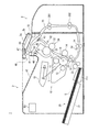
図1は、本実施の形態に係るプリンター1の構成を示す概略図である。
<First Embodiment>
Hereinafter, a first embodiment of an image forming apparatus according to the present invention will be described with reference to the drawings, taking a monochrome printer (hereinafter simply referred to as “printer”) as an example.
(1) Overall Configuration of Printer FIG. 1 is a schematic diagram showing the configuration of the
同図に示すプリンター1は、画像プロセス部10、給紙部20、定着部30、排紙反転部40および制御部50などからなる本体ユニット2と、本体ユニット2に着脱自在に取り付けられた、両面印刷のためのオプションユニット3(以下、「両面印刷ユニット3」という。)を備えている。プリンター1は、ネットワーク(例えばLAN)に接続されていて、外部の端末装置(不図示)からのプリントジョブの実行指示を受付けると、その指示に基づいてモノクロのトナー像を形成した後、シートSへの印刷処理を実行する。
The
画像プロセス部10は、感光体ドラム11、その周囲に配設された帯電器12、現像器13、転写ローラー14、および露光部15などを備える。
感光体ドラム11は、矢印方向に回転駆動される。帯電器12は、感光体ドラム11の外周面を所定電位に一様に帯電させ、その後、露光部15が感光体ドラム11の外周面を露光走査し、静電潜像を形成する。露光部15は、レーザーダイオードなどの発光素子を備え、印刷する画像データに基づいて制御部50において生成された駆動信号を受けてレーザー光Lを出射するように構成されている。
The
The photosensitive drum 11 is rotationally driven in the direction of the arrow. The
感光体ドラム11上に形成された静電潜像は、現像器13により現像され、トナー像が作像される。
上記トナー像の作像タイミングに合わせて、給紙部20からシートSが一枚ずつ給紙される。
給紙部20は、載置トレイ21、載置トレイ21上のシートSを1枚ずつ繰り出し給紙する給紙ローラー対22、感光体ドラム11と転写ローラー14との間の転写ニップ16にシートSを送り出すタイミングをとるためのレジストローラー対23などを備える。載置トレイ21には、載置されたシートSの先端側部分を給紙ローラー対22により繰り出し可能な高さ位置に昇降させる昇降板211が設けられている。
The electrostatic latent image formed on the photosensitive drum 11 is developed by the developing
The sheets S are fed one by one from the
The
給紙されたシートSが転写ニップ16を通過している間に、転写ローラー14に印加された転写電圧によって発生する転写電界の作用により、感光体ドラム11上に担持されたトナー像がシートSに転写される。
トナー像が転写されたシートSは、不図示の剥離爪によって感光体ドラム11から剥離されて定着部30へ搬送される。以下、給紙ローラー対22から定着部30に到る搬送路を「給紙路71」という。
While the fed sheet S passes through the
The sheet S to which the toner image has been transferred is peeled from the photosensitive drum 11 by a peeling claw (not shown) and conveyed to the
トナー像が転写された後の感光体ドラム11は、不図示のクリーナーによって表面に残留するトナーが除去され、かつ不図示のイレーサーにより残留電荷が消去される。
定着部30は、加熱ローラー31と加圧ローラー32を有し、両ローラー間に形成される定着ニップ33に、トナー像が転写されたシートSを挿入し加圧状態で加熱して、シートSに当該トナー像を熱定着させる。加熱ローラー31には、ハロゲンヒーター等の発熱体が内包されている。この発熱体のオンオフ制御を制御部50が行うことにより、加熱ローラー31の表面温度が定着温度になるように制御される。なお、定着部30の加熱方式は、上記のようなヒーター加熱方式に限定されず、例えば、電磁誘導加熱方式や抵抗発熱体を用いた加熱方式であってもよい。
After the toner image is transferred, the toner remaining on the surface of the photosensitive drum 11 is removed by a cleaner (not shown), and the residual charge is erased by an eraser (not shown).
The
トナー像が定着されたシートSは、排紙反転部40へ搬送される。
排紙反転部40は、排紙ローラー対41、排紙トレイ42、切換爪43などを有する。以下、定着ニップ33から排紙ローラー対41に到る搬送路を「排紙路72」という。
切換爪43は、支点を中心に揺動することにより、同図の実線で示す第1姿勢と破線で示す第2姿勢に切り替え可能に構成されている。切換爪43は、排紙路72内に、排紙ローラー対41に向かうシートSが存在しないときには、自重で第1姿勢となり、排紙ローラー対41に向かうシートSが切換爪43を通過するときには、シートSの先端が切換爪43を押し上げることにより、切換爪43が第2姿勢に切り替わる。このシートSの後端が切換爪43を通過すると、切換爪43は自重によって元の第1姿勢に戻るようになっている。
The sheet S on which the toner image is fixed is conveyed to the paper
The paper
The switching
排紙ローラー対41は、駆動モーター46により正逆回転駆動され、片面印刷モードでは、正回転してシートSを排紙トレイ42上に排出する。一方、両面印刷モードでは、表面(第1面)印刷されたシートSの後端が少なくとも切換爪43を通過するまでは、排紙ローラー対41が正回転し、その後逆回転することによってシートSを両面印刷ユニット3の再給紙路73へ送り出す(いわゆるスイッチバック方式)。
The paper
両面印刷ユニット3は、再給紙ローラー対301,302を有し、シートSを再給紙ローラー対301,302により搬送して、本体ユニット2の再給紙ローラー対24を介し給紙路71に戻す。これによりシートSの裏面(第2面)を感光体ドラム11側に向けて再搬送し、感光体ドラム11よりトナー像をシートSの裏面に転写させ、定着ニップ33で熱定着させる。こうして両面が印刷されたシートSは、排紙ローラー対41から排紙トレイ42上に排出される。
The
給紙路71、排紙路72および再給紙路73上の所定の位置には、搬送されるシートを検出するための公知のシート検出センサーが配設されており(例えば図中のS1〜S4など)、各シート検出センサーからの出力結果に基づき、制御部50がシートの搬送制御を行う。
制御部50は、シートの搬送制御だけでなく印刷処理を実行するため、画像プロセス部10、給紙部20、定着部30、排紙反転部40および両面印刷ユニット3を統括的に制御する。
A known sheet detection sensor for detecting a conveyed sheet is disposed at a predetermined position on the
The
上述した印刷処理では、定着部30でのシートSの加熱により、当該シートSに含まれた水分が放出され、水蒸気が発生する。この水蒸気を外部に排気するため、定着部30上方の本体ユニット2の外装カバー2aに排気口2bが設けられ、かつ定着部30と外装カバー2aとの間にあって、排紙路72を下側排紙ガイド45と構成する上側排紙ガイド44に、水蒸気を排気口2bに導く通気口47が設けられている。排気口2bおよび通気口47は、それぞれ複数の孔により構成されている。
In the printing process described above, when the sheet S is heated by the fixing
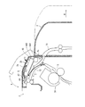
これらより、図2の拡大図で示すように、定着部30で発生した水蒸気の大部分が、排紙路72に沿うように上昇し(矢印F1)、上側排紙ガイド44の通気口47を通って(矢印F2)、排気口2bより装置外部に排気される(矢印F3)。
また、本実施の形態では、水蒸気が外装カバー2a内面に接触して結露した場合に(符号Dで示す部分)、その水滴Dが搬送されるシートS上に落下するのを防止するため、水滴を受け止めて回収するための機構が、上側排紙ガイド44に設けられている。
Accordingly, as shown in the enlarged view of FIG. 2, most of the water vapor generated in the fixing
In the present embodiment, when water vapor contacts the inner surface of the
(2)水滴を回収する機構について
まず、上側排紙ガイド44の構成について、図3を参照しながら詳しく説明する。
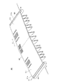
図3は、上側排紙ガイド44を示す斜視図である。
同図に示すように、上側排紙ガイド44は、板状のガイド本体441、ガイド本体441の下面(裏面)に設けられた複数のガイドリブ442a〜442m、ガイド本体441の上面に立設された水滴案内リブ443、一対の水滴回収容器444などを有し、これらが例えば樹脂材料により一体成形されている。
(2) Mechanism for collecting water droplets First, the configuration of the upper
FIG. 3 is a perspective view showing the upper
As shown in the drawing, the upper
水滴回収容器444は、ガイド本体441の、シート排出方向Cの上流側端部であって幅方向E(排紙路72の幅方向と同方向)の両端に、それぞれ設けられている。
ガイド本体441は、3つの板部分P1〜P3からなり、その上に落下した水滴を水滴回収容器444に集めるため、次のように構成されている。
2つの板部分P1,P2は、同じ台形状であり、ガイド本体441の幅方向Eの中央線CLに対して対称に配置され、かつそれぞれ幅方向Eの端に向かうほど低くなるように傾斜し(傾斜角θ1)、山型形状を形成している。残りの板部分P3は、板部分P1,P2のそれぞれの1辺を共有する三角形状である。
The water
The guide
The two plate portions P1 and P2 have the same trapezoidal shape, are arranged symmetrically with respect to the center line CL in the width direction E of the
ガイド本体441の長さL1は、排紙路72および再給紙路73内をシートSが通過する通過領域R1の最大幅W1(例えばシートサイズA3縦通しの幅)よりも長く設定され、一対の水滴回収容器444が、それぞれシートSが通過しない非通過領域(通過領域R1の幅方向両側の領域)上に配されている。
上記した通気口47は、このガイド本体441の下流側部分に形成されている。通気口47の形状や大きさ、数や配置などの構成は、定着部30で発生した水蒸気を通過させて、外装カバー2aの排気口2bから排気できればよく、特に限定するものではない。
A length L1 of the guide
The
ガイドリブ442a〜442mは、幅方向Eに所定の間隔をおいて配され、それぞれの下端面によりシートSを接触させて、排紙トレイ42へと案内している。すなわち、搬送路(排紙路72、および再給紙路73)の一部を形成している。本実施の形態では、ガイド本体441が山型形状であるので、ガイドリブ442a〜442mにおける下端面の位置を揃えるため、ガイド本体441からの突出量(矢印G方向の長さ)が調整されている。
The
水滴案内リブ443は、ガイド本体441のシート排出方向Cの上流側端部において幅方向Eに沿って配され、水滴が当該上流側端部から落下するのを防止するとともに、水滴を水滴回収容器444に向かうように案内する。
水滴案内リブ443の長さL2は、シートSの通過領域R1の最大幅W1以上、ガイド本体441の長さL1以下であり、通過領域R1の幅方向全体と重なるように配されている。これにより、水滴が、排紙路72および再給紙路73を搬送されるシートS上に落下するのを防止している。
The water
The length L2 of the water
また、ガイド本体441の、水滴回収容器444と水滴案内リブ443との間の部分は、傾斜をさらに強くして水滴を確実に水滴回収容器444に導くための導入路445として形成されている。
このように構成された上側排紙ガイド44が、不図示の取付部材により外装カバー2a内面に取着されている。その際、ガイド本体441が、シート排出方向Cの上流側が下流側よりも低く傾斜した状態に配設される。図中の傾斜角θ2は、そのときのガイド本体441の幅方向E両端P1a,P2aの水平方向に対する傾きを示す。これにより、ガイド本体441の板部分P1,P2の上面が、水滴回収容器444が設けられた2つの角部分に向かうほど低くなる傾斜面をなす。よって、その上に落下した水滴は、自重によって、当該角部分に向かうように移動し(一部は水滴案内リブ443に沿って移動)、最終的に水滴回収容器444に集められ、回収される(矢印D1〜D4)。
Further, a portion of the guide
The upper
本実施の形態では、ガイド本体441および水滴案内リブ443が、外装カバー2a内面から落下する水滴を受け止めて一対の水滴回収容器444に案内する水滴案内部材として機能する。そして、このガイド本体441および水滴案内リブ443と、一対の水滴回収容器444とが、水滴を回収する機構を構成している。
ガイド本体441の傾斜を示す上記傾斜角θ1,θ2の大きさは、特に限定するものではないが、傾斜角θ1は、大きくなるほどガイド本体441が嵩高くなって装置の大型化を招くので、これを抑制する上で、可能な限り小さく設定するのが望ましい。一方、傾斜角θ2は、排紙路72などの装置内のレイアウト等、設計条件に応じて決定すればよい。
In the present embodiment, the guide
The magnitudes of the inclination angles θ1 and θ2 indicating the inclination of the
なお、傾斜角θ1が大きいと、水滴の、ガイド本体441の幅方向Eの移動速度が速くなって、その両端P1a,P2aから落下するおそれがある。そこで、水滴の幅方向Eの移動速度を抑えて、両端P1a,P2aに到達した水滴が端縁の傾斜(傾斜角θ2)に沿って移動し水滴回収容器444に導かれるように(矢印D5,D6)、傾斜角θ1を小さくしている。傾斜角θ1の大きさは予め実験により求められている。
If the inclination angle θ1 is large, the moving speed of the water droplets in the width direction E of the
もっとも、両端P1a,P2aから水滴が落下したとしても、そこはシートSの非通過領域になるので、シートSに皺が生じたり、印刷画像の品質低下を招くことはないが、定着部30や画像プロセス部10の上に水滴が落下するのを防止するため、このように傾斜角θ1を小さく設定する、または、両端P1a,P2aに水滴案内リブや樋などを設けるようにするのが望ましい。
However, even if water droplets fall from both ends P1a and P2a, they become non-passing areas of the sheet S, so that the sheet S will not be wrinkled and the quality of the printed image will not be deteriorated. In order to prevent water droplets from falling on the
水滴回収容器444に回収された水滴は、装置内の熱によって自然蒸発して排気される。水滴回収容器444の大きさは、大量に連続印刷した場合でも、水滴が溢れることがないように大きくするのが望ましいが、装置の大型化に繋がるため制限されてしまう。そのため、最悪の場合には、水滴回収容器444から水滴が溢れ出るおそれがある。しかしながら、上述したように、本実施の形態では、水滴回収容器444がシートSの非通過領域の上にあるので、容器から溢れ出た水が、搬送されるシートS上に落ちることはなく、よって、シートの皺や印刷画像の品質低下を防止することができる。
The water droplets collected in the water
本実施の形態では、水蒸気や結露した水滴に起因する問題が生じるのを抑制するため、上記以外にも次のような構成が設けられている。これについて、図2に戻って説明する
まず、水滴案内リブ443の上端を外装カバー2aの内面に当接させ、それにより、外装カバー2aの内面に付着した水滴が、当該内面に沿って外装カバー2aの下端側へと流れ、再給紙路73を搬送されるシートS上に落下するのを防止している。また、水蒸気の流れを規制して排気口2bに導くガイドとしても機能する。
In the present embodiment, the following configuration is provided in addition to the above in order to prevent problems caused by water vapor or condensed water droplets. This will be described with reference back to FIG. 2. First, the upper end of the water
外装カバー2aの排気口2bを、上側排紙ガイド44の通気口47と上下方向に重ならない位置に設け、水蒸気を上側排紙ガイド44と外装カバー2aとの間の隙間48を通過させることで、水蒸気密度が高いときには隙間48内で結露して、排気口2bから乾いた水蒸気が排出されるようにしている。これにより、水蒸気密度が高いまま排出され、外気に冷やされて生じた湯気を、発煙しているとユーザーが誤解するのを防止できる。
The
また、隙間48が、排紙路72と外気との間を断熱する役割を果たすので、排紙路72内で水蒸気が冷やされて結露するのを防止することができる。
上側排紙ガイド44に対向(対応)する外装カバー2aは、本体ユニット2に設けられた支軸2cを中心に矢印A方向に回動可能に設けられており、両面印刷ユニット3を矢印B方向に移動させ本体ユニット2から離した状態において開閉自在に構成されている。ジャム処理や点検などの際、外装カバー2aを開くことにより、外装カバー2aに取着された上側排紙ガイド44も回動され、排紙ローラー対41および排紙路72を開放できるようになっている。この場合、水滴回収容器444が、この回動中心の支軸2cに近い位置にあるので、支軸2cから離れた位置にある場合と比べて、外装カバー2aの開閉時における水滴回収容器444の移動加速度が小さく、よって内部の水滴が飛び出しにくい構成となっている。外装カバー2aの開閉時に、水滴回収容器444から水滴が飛び出すようなことがあると、ユーザーに不快感を与えるとともに、水滴が飛び出さないように外装カバー2aの開閉作業をより慎重に行わざるを得ないので、使い勝手が悪くなる。このような問題が生じないように、本実施の形態では、支軸2cに近い位置に水滴回収容器444が設けられている。
<第2の実施の形態>
第2の実施の形態では、上側排紙ガイドが有するガイド本体は平板形状であり、かつ水滴案内リブがアーチ状(湾曲形状)である点で、第1の実施の形態の上側排紙ガイド44とは相違する。
Further, since the
The
<Second Embodiment>
In the second embodiment, the
また上記相違に伴い、上側排紙ガイドの他の構成が若干異なっている。その他の構成については、基本的に第1の実施の形態のプリンター1と同様であるので、同じ構成については、同じ符号で示し、その説明を省略する。
図4は、本実施の形態の上側排紙ガイド100の構成を示す斜視図である。
同図に示すように、上側排紙ガイド100は、ガイド本体101、複数のガイドリブ102、水滴案内リブ103、一対の水滴回収容器104を有する。
In addition, with the difference, other configurations of the upper sheet discharge guide are slightly different. Since other configurations are basically the same as those of the
FIG. 4 is a perspective view showing the configuration of the upper
As shown in the figure, the upper
本実施の形態では、ガイド本体101が平板部材からなる。この場合、複数のガイドリブ102の下端面の位置を揃えるためには、ガイド本体101からの突出量を全て同じにすればよく、本実施の形態においても、これと同様となっている。
水滴案内リブ103は、幅方向E中央部が、シート排出方向C下流側に突出し、その両端がそれぞれ上流側の水滴回収容器104に向けて延出された湾曲形状をしている。この水滴案内リブ103の幅方向Eの長さL4は、シートSの通過領域R1の最大幅W1以上、ガイド本体101の長さL3未満であり、通過領域R1の幅方向全体と重なるように配される。
In the present embodiment, the
The water
このガイド本体101が、外装カバー2aに取着されたとき、図5に示すように、第1の実施の形態と同様、シート排出方向Cの上流側が下流側よりも低く傾斜した状態に配設される。よって、ガイド本体101の上面が、上流側に向かうほど低くなる傾斜面をなす。なお、ガイド本体101の幅方向は水平方向に対して傾いていない状態となっている。
ガイド本体101は、その上流側端部101aが上方に少し折り曲げられることにより、断面V字状の樋106が形成されている。
When this guide
The guide
水滴案内リブ103と外装カバー2aとの間には所定の隙間107が形成され、それによりガイド本体101の通気口105を通過した水蒸気が(矢印F4)、隙間107を通って外装カバー2aの排気口2bより排気されるようになっている(矢印F5)。
本実施の形態では、ガイド本体101の上流側端部101aが、外装カバー2aの内面に当接され、外装カバー2aの内面に沿って流れ出した水滴が、再給紙路73のシートSの通過領域上に落下するのを防止している。
A
In the present embodiment, the
外装カバー2a内面に結露し(符号Dで示す部分)、ガイド本体101の水滴案内リブ103より下流側の部分に落下した水滴は、水滴案内リブ103に沿って移動し(矢印D7)、水滴回収容器104に回収される。一方、水滴案内リブ103よりも上流側に落下した水滴は、図4に示すように、ガイド本体101の傾斜面に沿って樋106へと移動し(矢印D8)、樋106により水滴回収容器104へと導かれ(矢印D9)、回収される。
The water droplets that have condensed on the inner surface of the
本実施の形態においても、結露した水滴を回収する水滴回収容器104が、シートSの最大通過領域よりも外側に配されているので、第1の実施の形態と同様の効果を得ることができる。
<第3の実施の形態>
第3の実施の形態では、ガイド本体に設けられたアーチ状の水滴案内リブが複数条形成されている点で、第2の実施の形態とは相違する。
Also in the present embodiment, since the water
<Third Embodiment>
The third embodiment is different from the second embodiment in that a plurality of arch-shaped water droplet guide ribs provided on the guide body are formed.
その他の構成については、基本的に第2の実施の形態と同様であるので、同じ構成については、同じ符号で示し、その説明を省略する。
図6は、本実施の形態の上側排紙ガイド200の構成を示す斜視図である。
同図に示すように、上側排紙ガイド200のガイド本体101の上面には、複数の水滴案内リブ201〜204が立設されている。
Since the other configuration is basically the same as that of the second embodiment, the same configuration is denoted by the same reference numeral, and the description thereof is omitted.
FIG. 6 is a perspective view showing a configuration of the upper
As shown in the figure, a plurality of water
このように複数の水滴案内リブ201〜204を設けた理由について説明する。
ガイド本体101の樋106は、水平方向に対して傾いていないので、内部にある程度水滴が溜まってしまう。なお、樋106内に水滴が溜まれば、樋106よりも低い位置の水滴回収容器104へと流れ出すので、印刷中に樋106から水滴が落下するおそれはないが、上述したように、ジャム処理や点検などで外装カバー2aを開いたとき、樋106に溜まっていた水滴が落下する場合がある。このようなことから、本実施の形態では、ガイド本体101上に複数の水滴案内リブ201〜204を設けて、樋106にあまり水滴が溜まらないように構成している。
The reason for providing the plurality of water
Since the
水滴案内リブの数は、4つに限定するものではなく、2つでも、3つでもよく、また5つ以上でも構わない。
[変形例]
以上、本発明を実施の形態に基づいて説明してきたが、本発明が上述の実施の形態に限定されないのは勿論であり、以下のような変形例を実施することができる。
The number of water droplet guide ribs is not limited to four, but may be two, three, or five or more.
[Modification]
As described above, the present invention has been described based on the embodiment. However, the present invention is not limited to the above-described embodiment, and the following modifications can be implemented.
(1)第1の実施の形態では、ガイド本体441が山型形状を有する構成を示したが、これに限定するものではない。例えば、ガイド本体の幅方向の中央部分が、上方に突出するように形成された湾曲形状であっても構わない。
また、ガイド本体の山型形状を形成するのに、2つの板部分P1,P2を組み合わせた構成を示したが、これに限定するものではない。例えば、厚めの板部材を用いて、その上面の幅方向の断面形状が、山型形状になるように加工しても構わない。
(1) In the first embodiment, the guide
Moreover, although the structure which combined the two board parts P1 and P2 was shown in order to form the mountain shape of a guide main body, it is not limited to this. For example, a thick plate member may be used and processed so that the cross-sectional shape in the width direction of the upper surface thereof has a mountain shape.
さらに、山型形状または湾曲形状のガイド本体において、頂部(最も高い部分)が、幅方向の中央位置になく、ずれた位置にあっても構わない。もっとも、一対の水滴回収容器の大きさが等しい場合には、回収される水滴の量のバランスをとるため、ガイド本体の頂部(最も高い部分)が幅方向の中央位置にあるのが望ましい。
(2)第2および第3の実施の形態では、ガイド本体101の外装カバー2aに取着された状態において、ガイド本体101の幅方向が水平方向に対して傾いていない構成を示したが、これに限定するものではない。
Furthermore, in the guide body having a mountain shape or a curved shape, the top portion (the highest portion) may not be at the center position in the width direction but at a shifted position. However, when the sizes of the pair of water droplet collection containers are equal, it is desirable that the top portion (the highest portion) of the guide body is at the center position in the width direction in order to balance the amount of water droplets to be collected.
(2) In the second and third embodiments, the configuration in which the width direction of the guide
例えば、ガイド本体101の幅方向の一方側に、水滴回収容器を設けるスペースが確保し難い場合などには、当該幅方向を水平方向に対して傾けて、低くなる方の端部にのみ水滴回収容器を設けるように構成しても構わない。
(3)第2および第3の実施の形態では、ガイド本体101にアーチ状(湾曲形状)の水滴案内リブが設けられた構成を示したが、これに限定するものではなく、上面視で逆V字状(2つの直線状部分からなる構成)の水滴案内リブを用いることもできる。
For example, when it is difficult to secure a space for providing a water droplet collection container on one side in the width direction of the
(3) In the second and third embodiments, the configuration in which the
水滴案内リブは、ガイド本体上に落下した水滴を、水滴回収容器側へと案内できればよく、その形状、配置、数等の構成は、適宜選択することができる。
したがって、例えば、第1の実施の形態における山型形状を有するガイド本体441に、アーチ状の水滴案内リブを設けても構わない。
(4)上記実施の形態では、水滴回収容器444(104)と、ガイド本体441(101)とが一体成形された構成を用いて説明したが、これに限定するものではない。
The water droplet guide ribs only have to be able to guide the water droplets dropped on the guide body to the water droplet collection container side, and the shape, arrangement, number, and the like can be selected as appropriate.
Therefore, for example, an arch-shaped water droplet guide rib may be provided on the
(4) In the above embodiment, the water droplet collection container 444 (104) and the guide main body 441 (101) have been described as being integrally formed. However, the present invention is not limited to this.
例えば、別体で形成した水滴回収容器を、ガイド本体に取り付ける構成としても構わない。また、別体で形成した水滴回収容器が、ガイド本体から離間していてもよく、ガイド本体で受け止め集めた水滴が、水滴回収容器内に落下する、または流れ込むように構成されていればよい。
(5)第1の実施の形態では、外装カバー2a内面から落下する水滴を受け止めて一対の水滴回収容器に案内する水滴案内部材が、ガイド本体と水滴案内リブとからなる構成を示したが、これに限定するものではない。
For example, a configuration may be adopted in which a water droplet collection container formed separately is attached to the guide body. Further, the water droplet collection container formed separately may be separated from the guide main body, and the water drops received and collected by the guide main body may be configured to fall or flow into the water drop collection container.
(5) In the first embodiment, the water droplet guide member that receives the water droplet falling from the inner surface of the
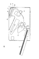
例えば、図7に示すように、水滴案内リブおよび樋などを設けないで、ガイド本体401のみで水滴案内部材を構成することもできる。
同図に示すガイド本体401は、2つの板部材P11,P12により山型形状に形成されてなり、一対の水滴回収容器404が、ガイド本体401の幅方向E両端P11a,P12aの端縁全体に及ぶ大きさを有してなる。このガイド本体401を、幅方向E両端P11a,P12aの水平方向に対する傾きをなくした状態にして(傾斜角θ3=0°)、外装カバーに取着することにより、ガイド本体401上に落下した水滴を、板部材P11,P12の傾斜面に沿って幅方向E両側に移動させることができ、水滴回収容器404によって回収することができる。
For example, as shown in FIG. 7, the water droplet guide member can be configured with only the guide
The guide
(6)上記実施の形態では、外装カバー2a内面から落下する水滴Dを受け止めて回収する機構が、排紙路72を構成する上側排紙ガイド44に設けられた構成を示したが、これに限定するものではない。
例えば、本体ユニット2の外装カバーと上側排紙ガイドとの隙間を拡げて、その間に、落下する水滴Dを受け止めて回収する専用の板状の水滴案内部材および水滴回収容器を設ける構成とすることができる。もっとも、水滴回収容器は、上記(4)で記述したように、水滴案内部材に取り付けなくてもよいので、上側排紙ガイド44の横の位置に配置するようにすれば、本体ユニット2の高さが高くなるのを抑制できる。
(6) In the above embodiment, the configuration in which the mechanism for receiving and collecting the water drop D falling from the inner surface of the
For example, the gap between the exterior cover of the
(7)第1の実施の形態では、水滴案内リブ443の上端を外装カバー2aの内面に当接させた構成を示したが、これに限定するものではない。
外装カバー2aの内面に付着した水滴が、外装カバー2aの下端側へと流れるのを防止できればよく、例えば、外装カバー2aの内面に水滴の移動を規制するリブを設ける構成としても構わない。この場合、当該リブが、水蒸気を排気口2bに導くガイドとしても機能するように構成するのが望ましい。
(7) In the first embodiment, the configuration in which the upper end of the water
It is only necessary to prevent water droplets adhering to the inner surface of the
(8)第1の実施の形態では、ガイド本体441の、水滴回収容器444と水滴案内リブ443との間の部分に導入路445が形成された構成を示したが、これに限定するものではなく、導入路445が形成されていない構成としても構わない。
例えば、水滴案内リブ443の両端を、それぞれ水滴回収容器444まで延長させれば、水滴を確実に水滴回収容器444に導くことができる。また、水滴案内リブ443の両端を延長させなくても、ガイド本体441の傾斜角θ1,θ2を調整することによって、水滴をほぼ確実に水滴回収容器444に導くように設定することが可能である。もっとも、水滴案内リブ443が、通過領域R1の幅方向全体と重なるように配されている限り、水滴案内リブ443と水滴回収容器444との間で水滴が落下したとしても、そこはシートSの非通過領域になるので、シートSに皺が生じたり、印刷画像の品質低下を招くことはない。
(8) In the first embodiment, the structure in which the
For example, if both ends of the water
(9)第2の実施の形態では、ガイド本体101の上流側端部101aが、外装カバー2aの内面に当接された構成を示したが、これに限定するものではない。
上記変形例(6)と同様、外装カバー2aの内面に付着した水滴が、外装カバー2aの下端側へと流れるのを防止できればよく、例えば、外装カバー2aの内面に水滴の移動を規制するリブを設ける構成としても構わない。
(9) In the second embodiment, the
Similarly to the modification (6), it is only necessary to prevent water droplets attached to the inner surface of the
(10)第2および第3の実施の形態では、ガイド本体101に設けられた樋106の長手方向が水平方向に対して傾いていない構成を示したが、これに限定するものではない。
例えば、樋106の長手方向が、水滴回収容器104に向かうほど低くなるように傾斜した構成にすることができる。この場合、樋106内の水滴を、傾斜によって移動させることができるので、ある程度溜まるのを待つ必要がなく、樋106内に水滴が溜まるのを抑制できる。樋106内に溜まる水滴が少なくなれば、その分、樋106内で水滴が自然蒸発するのが早くなるので、ジャム処理や点検などで外装カバー2aを開いたとき、樋106に溜まっていた水滴が落下するのを抑制することができる。
(10) In the second and third embodiments, the configuration in which the longitudinal direction of the
For example, a configuration in which the longitudinal direction of the
(11)上記実施の形態では、両面印刷ユニット3が取り付けられたプリンター1を用いて説明したが、本発明の適用範囲は、これに限らず、例えば、図8に示すプリンター300のような、両面印刷ユニットオプションを具備していないプリンターにも適用することができる。
(12)上記実施の形態では、画像形成装置として、モノクロ複写機を用いて説明したが、本発明の適用範囲は、これに限らず、定着装置を有していれば、タンデム型カラー複写機、タンデム型カラープリンター、モノクロプリンター、ファクシミリ装置などに適用することができる。
(11) Although the above embodiment has been described using the
(12) In the above embodiment, a monochrome copying machine is used as the image forming apparatus. However, the scope of application of the present invention is not limited to this, and a tandem color copying machine can be used as long as it has a fixing device. It can be applied to tandem color printers, monochrome printers, facsimile machines, and the like.
また、上記実施の形態及び変形例の内容は、可能な限り組み合わせても構わない。 Further, the contents of the above-described embodiment and modification examples may be combined as much as possible.
本発明は、定着器で発生した水蒸気が装置内で結露し、その水滴が用紙に付着するのを防止する技術として有用である。 INDUSTRIAL APPLICABILITY The present invention is useful as a technique for preventing water vapor generated in the fixing device from condensing in the apparatus and preventing the water droplets from adhering to the paper.
1 プリンター
2a 外装カバー
2b 排気口
2c 支軸
3 両面印刷ユニット
10 画像プロセス部
20 給紙部
30 定着部
31 加熱ローラー
32 加圧ローラー
33 定着ニップ
40 排紙反転部
41 排紙ローラー対
42 排紙トレイ
44 上側排紙ガイド
441 ガイド本体(水滴案内部材)
443 水滴案内リブ
444 水滴回収容器(結露回収容器)
47 通気口
72 排紙路
73 再給紙路
100,200 上側排紙ガイド
101 ガイド本体(水滴案内部材)
103,201〜204 水滴案内リブ
104 水滴回収容器(結露回収容器)
105 通気口
R1 通過領域
DESCRIPTION OF
443 Water drop guide
47
103, 201-204 Water
105 Vent R1 passage area
Claims (9)
熱定着時にシートから発生した水蒸気が定着器上方で結露して落下する水滴を、板状の水滴案内部材で受け止めて結露回収容器まで案内して回収する機構を備えており、
装置上方から見たときに、前記結露回収容器が、前記シートの通過領域よりシート幅方向外側の領域に配設されている
ことを特徴とする画像形成装置。 An image forming apparatus including a fixing device that heat-fixes a sheet on which an unfixed image is formed by bringing the sheet into contact with a heating rotator,
It is equipped with a mechanism for collecting and dropping water droplets generated by condensation of water vapor generated from the sheet at the time of heat fixing above the fixing device and receiving it by a plate-shaped water droplet guide member to a condensation collection container.
The image forming apparatus, wherein when viewed from above the apparatus, the condensation collection container is disposed in an area outside the sheet passing area in the sheet width direction.
ことを特徴とする請求項1に記載の画像形成装置。 The dew condensation collection container is provided on one side in the sheet width direction, and the upper surface of the water droplet guide member is provided with one continuous inclined surface or curved surface that becomes lower toward the dew condensation collection container. The image forming apparatus according to claim 1.
ことを特徴とする請求項1に記載の画像形成装置。 The dew collection container is provided on both sides in the sheet width direction, and the upper surface of the water droplet guide member has a cross-section perpendicular to the sheet conveying direction and a curved shape with an upward convex shape. The image forming apparatus according to claim 1, wherein the image forming apparatus is lowered toward the first position.
ことを特徴とする請求項1から3のいずれか1項に記載の画像形成装置。 The rib which guides the water droplet which flowed down along the said water drop guide member toward the said dew condensation collection | recovery container on the upper surface of a water drop guide member is standingly arranged by 1 item | s or more items from Claim 1 characterized by the above-mentioned. 4. The image forming apparatus according to any one of items 3.
ことを特徴とする請求項4に記載の画像形成装置。 The image forming apparatus according to claim 4, wherein the rib has a curved shape when viewed from above the apparatus.
前記リブは、上記通気孔が形成された位置よりも低い位置に立設されている
ことを特徴とする請求項4または5に記載の画像形成装置。 The water droplet guide member is disposed so that the upper surface thereof is inclined such that the first side of both sides in the sheet conveying direction is higher than the other second side, and a part of the first side is provided with a fixing unit. A vent for passing the rising water vapor is formed,
The image forming apparatus according to claim 4, wherein the rib is erected at a position lower than a position where the vent hole is formed.
ことを特徴とする請求項6に記載の画像形成装置。 The image forming apparatus according to claim 6, wherein an exhaust hole is provided above a portion of the apparatus housing on the second side of the water droplet guide member.
ことを特徴とする請求項6または7か1項に記載の画像形成装置。 The portion corresponding to the water droplet guide member of the apparatus housing can be opened around the support shaft on the second side together with the water droplet guide member. Image forming apparatus.
ことを特徴とする請求項1から8のいずれか1項に記載の画像形成装置。 9. The image forming apparatus according to claim 1, wherein a back surface side of the water droplet guide member functions as a sheet guide for guiding a sheet.
Priority Applications (2)
| Application Number | Priority Date | Filing Date | Title |
|---|---|---|---|
| JP2012092870A JP5648651B2 (en) | 2012-04-16 | 2012-04-16 | Image forming apparatus |
| US13/862,802 US9008535B2 (en) | 2012-04-16 | 2013-04-15 | Image forming apparatus having mechanism for preventing condensation from contacting a sheet |
Applications Claiming Priority (1)
| Application Number | Priority Date | Filing Date | Title |
|---|---|---|---|
| JP2012092870A JP5648651B2 (en) | 2012-04-16 | 2012-04-16 | Image forming apparatus |
Publications (2)
| Publication Number | Publication Date |
|---|---|
| JP2013222026A true JP2013222026A (en) | 2013-10-28 |
| JP5648651B2 JP5648651B2 (en) | 2015-01-07 |
Family
ID=49325205
Family Applications (1)
| Application Number | Title | Priority Date | Filing Date |
|---|---|---|---|
| JP2012092870A Expired - Fee Related JP5648651B2 (en) | 2012-04-16 | 2012-04-16 | Image forming apparatus |
Country Status (2)
| Country | Link |
|---|---|
| US (1) | US9008535B2 (en) |
| JP (1) | JP5648651B2 (en) |
Cited By (4)
| Publication number | Priority date | Publication date | Assignee | Title |
|---|---|---|---|---|
| JP2014157322A (en) * | 2013-02-18 | 2014-08-28 | Ricoh Co Ltd | Image forming apparatus |
| JP2015087654A (en) * | 2013-10-31 | 2015-05-07 | ブラザー工業株式会社 | Image forming apparatus |
| JP2015101066A (en) * | 2013-11-28 | 2015-06-04 | ブラザー工業株式会社 | Image formation device |
| KR20170001596U (en) * | 2015-10-28 | 2017-05-10 | 주식회사 서원기술 | Pipe connector |
Families Citing this family (8)
| Publication number | Priority date | Publication date | Assignee | Title |
|---|---|---|---|---|
| US9213309B2 (en) * | 2013-10-31 | 2015-12-15 | Brother Kogyo Kabushiki Kaisha | Image forming apparatus having image forming unit |
| JP2015096917A (en) | 2013-11-15 | 2015-05-21 | ブラザー工業株式会社 | Image forming apparatus |
| US9207628B2 (en) | 2013-11-15 | 2015-12-08 | Brother Kogyo Kabushiki Kaisha | Image forming apparatus provided with structure for receiving liquid |
| JP2015102828A (en) | 2013-11-28 | 2015-06-04 | ブラザー工業株式会社 | Image forming apparatus |
| US9483014B2 (en) | 2013-11-29 | 2016-11-01 | Brother Kogyo Kabushiki Kaisha | Image forming apparatus having panel unit |
| JP7187204B2 (en) * | 2018-08-03 | 2022-12-12 | キヤノン株式会社 | Image forming device and anti-condensation system |
| JP2022021841A (en) * | 2020-07-22 | 2022-02-03 | キヤノン株式会社 | Image formation device and sheet conveyance device |
| JP2023085106A (en) * | 2021-12-08 | 2023-06-20 | キヤノン株式会社 | Sheet conveying device and image forming apparatus |
Citations (5)
| Publication number | Priority date | Publication date | Assignee | Title |
|---|---|---|---|---|
| JPH0916005A (en) * | 1995-06-29 | 1997-01-17 | Canon Inc | Heater and image forming device |
| JP2006276215A (en) * | 2005-03-28 | 2006-10-12 | Fuji Xerox Co Ltd | Image forming apparatus |
| JP2006322994A (en) * | 2005-05-17 | 2006-11-30 | Canon Inc | Image forming apparatus |
| JP2009134207A (en) * | 2007-12-03 | 2009-06-18 | Canon Finetech Inc | Image forming apparatus |
| JP2011095569A (en) * | 2009-10-30 | 2011-05-12 | Konica Minolta Business Technologies Inc | Image forming apparatus |
Family Cites Families (4)
| Publication number | Priority date | Publication date | Assignee | Title |
|---|---|---|---|---|
| JPH0535135A (en) | 1991-05-13 | 1993-02-12 | Ricoh Co Ltd | Fixing device for electrophotographic copying device |
| JP2007304161A (en) | 2006-05-09 | 2007-11-22 | Ricoh Co Ltd | Cooling system and image forming apparatus |
| JP5239560B2 (en) * | 2007-12-28 | 2013-07-17 | 株式会社リコー | Image forming apparatus |
| JP5418092B2 (en) * | 2009-09-11 | 2014-02-19 | 株式会社リコー | Image forming apparatus |
-
2012
- 2012-04-16 JP JP2012092870A patent/JP5648651B2/en not_active Expired - Fee Related
-
2013
- 2013-04-15 US US13/862,802 patent/US9008535B2/en not_active Expired - Fee Related
Patent Citations (5)
| Publication number | Priority date | Publication date | Assignee | Title |
|---|---|---|---|---|
| JPH0916005A (en) * | 1995-06-29 | 1997-01-17 | Canon Inc | Heater and image forming device |
| JP2006276215A (en) * | 2005-03-28 | 2006-10-12 | Fuji Xerox Co Ltd | Image forming apparatus |
| JP2006322994A (en) * | 2005-05-17 | 2006-11-30 | Canon Inc | Image forming apparatus |
| JP2009134207A (en) * | 2007-12-03 | 2009-06-18 | Canon Finetech Inc | Image forming apparatus |
| JP2011095569A (en) * | 2009-10-30 | 2011-05-12 | Konica Minolta Business Technologies Inc | Image forming apparatus |
Cited By (5)
| Publication number | Priority date | Publication date | Assignee | Title |
|---|---|---|---|---|
| JP2014157322A (en) * | 2013-02-18 | 2014-08-28 | Ricoh Co Ltd | Image forming apparatus |
| JP2015087654A (en) * | 2013-10-31 | 2015-05-07 | ブラザー工業株式会社 | Image forming apparatus |
| JP2015101066A (en) * | 2013-11-28 | 2015-06-04 | ブラザー工業株式会社 | Image formation device |
| KR20170001596U (en) * | 2015-10-28 | 2017-05-10 | 주식회사 서원기술 | Pipe connector |
| KR200483835Y1 (en) * | 2015-10-28 | 2017-06-29 | 주식회사 서원기술 | Pipe connector |
Also Published As
| Publication number | Publication date |
|---|---|
| US9008535B2 (en) | 2015-04-14 |
| US20130272744A1 (en) | 2013-10-17 |
| JP5648651B2 (en) | 2015-01-07 |
Similar Documents
| Publication | Publication Date | Title |
|---|---|---|
| JP5648651B2 (en) | Image forming apparatus | |
| JP5865823B2 (en) | Image forming apparatus | |
| JP5842679B2 (en) | Recording medium discharge apparatus and image forming apparatus | |
| JP4890896B2 (en) | Image forming apparatus | |
| JP5239560B2 (en) | Image forming apparatus | |
| JP5339931B2 (en) | Sheet discharging apparatus and image forming apparatus | |
| JP7112673B2 (en) | image forming device | |
| JP2007219032A (en) | Image forming device | |
| JP2010036995A (en) | Image forming device | |
| JP2008139396A (en) | Image forming apparatus | |
| JP2006248738A (en) | Image formation device | |
| JP4946392B2 (en) | Image forming apparatus | |
| JP5322698B2 (en) | Image forming apparatus | |
| JP6233259B2 (en) | Image forming apparatus | |
| JP4882752B2 (en) | Recording apparatus and image forming apparatus | |
| JP4693662B2 (en) | Sheet discharging apparatus and image forming apparatus having the same | |
| JP2011059483A (en) | Paper carrying device and image forming apparatus | |
| JP2005255386A (en) | Image forming device | |
| JP2006176265A (en) | Sheet conveying device and image forming device | |
| JP2010030749A (en) | Image forming device | |
| JP2007017612A (en) | Image forming apparatus | |
| JP2005227724A (en) | Image forming apparatus | |
| JP6868179B2 (en) | Image forming device | |
| JP2003186326A (en) | Image-forming apparatus | |
| JP2006076702A (en) | Sheet handling device, and image forming device with the same |
Legal Events
| Date | Code | Title | Description |
|---|---|---|---|
| A621 | Written request for application examination |
Free format text: JAPANESE INTERMEDIATE CODE: A621 Effective date: 20140313 |
|
| RD02 | Notification of acceptance of power of attorney |
Free format text: JAPANESE INTERMEDIATE CODE: A7422 Effective date: 20140613 |
|
| A977 | Report on retrieval |
Free format text: JAPANESE INTERMEDIATE CODE: A971007 Effective date: 20140711 |
|
| A131 | Notification of reasons for refusal |
Free format text: JAPANESE INTERMEDIATE CODE: A131 Effective date: 20140722 |
|
| A521 | Written amendment |
Free format text: JAPANESE INTERMEDIATE CODE: A523 Effective date: 20140917 |
|
| TRDD | Decision of grant or rejection written | ||
| A01 | Written decision to grant a patent or to grant a registration (utility model) |
Free format text: JAPANESE INTERMEDIATE CODE: A01 Effective date: 20141014 |
|
| A61 | First payment of annual fees (during grant procedure) |
Free format text: JAPANESE INTERMEDIATE CODE: A61 Effective date: 20141027 |
|
| R150 | Certificate of patent or registration of utility model |
Ref document number: 5648651 Country of ref document: JP Free format text: JAPANESE INTERMEDIATE CODE: R150 |
|
| LAPS | Cancellation because of no payment of annual fees |