JP2013220249A - Air massage machine - Google Patents
Air massage machine Download PDFInfo
- Publication number
- JP2013220249A JP2013220249A JP2012094603A JP2012094603A JP2013220249A JP 2013220249 A JP2013220249 A JP 2013220249A JP 2012094603 A JP2012094603 A JP 2012094603A JP 2012094603 A JP2012094603 A JP 2012094603A JP 2013220249 A JP2013220249 A JP 2013220249A
- Authority
- JP
- Japan
- Prior art keywords
- treatment
- expansion
- airbag
- contraction
- contraction part
- Prior art date
- Legal status (The legal status is an assumption and is not a legal conclusion. Google has not performed a legal analysis and makes no representation as to the accuracy of the status listed.)
- Granted
Links
Images


Landscapes
- Massaging Devices (AREA)
Abstract
【課題】エアバッグの膨張収縮に伴って施術点の位置ずれがない上に、膨張収縮ストロークを長くできるようにする。
【解決手段】エアの供給と排出により膨張収縮する膨張収縮部21が形成されたエアバッグ22を備えるエアマッサージ機において、施術を行う施術位置に備えられる施術用膨張収縮部21aの下に、該施術用膨張収縮部21aの平面視位置を規制しつつ前記施術用膨張収縮部21aを真っ直ぐ上に持ち上げる規制用膨張収縮部21bを備えたエアバッグユニット25を有するエアマッサージ機11。
【選択図】図3An object of the present invention is to enable a long expansion / contraction stroke in addition to the displacement of a treatment point with the expansion / contraction of an airbag.
In an air massage machine including an airbag 22 formed with an inflating / shrinking portion 21 that inflates / shrinks by supply / discharge of air, under the treatment inflating / shrinking portion 21a provided at a treatment position for performing the treatment, An air massage machine 11 having an airbag unit 25 including a restricting inflation / deflation part 21b that lifts the treatment inflation / deflation part 21a straight up while restricting a planar view position of the treatment inflation / deflation part 21a.
[Selection] Figure 3
Description
この発明は、エアバッグの膨張と収縮により人体をマッサージするエアマッサージ機に関し、より詳しくは、膨張収縮のストローク(一動き)を長くできるようなエアマッサージ機に関する。 The present invention relates to an air massage machine that massages a human body by inflation and contraction of an airbag, and more particularly, to an air massage machine that can lengthen a stroke (one movement) of expansion and contraction.
エアバッグの膨張量はエアバッグ内の気室の容積や形状によって決まるので、気室の容積を大きくすれば膨張収縮のストロークを長くすることができる。しかし、マッサージするには短時間で膨張収縮することが必要である。 Since the expansion amount of the airbag is determined by the volume and shape of the air chamber in the air bag, the expansion and contraction stroke can be lengthened by increasing the volume of the air chamber. However, in order to massage, it is necessary to expand and contract in a short time.
このため、膨張収縮のストロークを長くするのに2枚のエアバッグを重ね合わせることが行われている。下記特許文献1に開示されているマッサージ装置の尻用マッサージユニットでは、施療部材の可動支持板の下に2枚のエアバッグが、エアバッグの片側を固定した重合状態で備えられている(特許文献1の段落[0051]、[0053]、図5参照)。 For this reason, two airbags are overlapped in order to lengthen the stroke of expansion and contraction. In the massage unit for the buttocks of the massage device disclosed in Patent Document 1 below, two airbags are provided in a superposed state in which one side of the airbag is fixed under the movable support plate of the treatment member (patent) (Refer to paragraphs [0051] and [0053] of FIG. 1 and FIG. 5).
この構成により、施療部材を短時間で大きく傾けることができ、より効果的なマッサージができる。 With this configuration, the treatment member can be greatly tilted in a short time, and more effective massage can be performed.
しかし、エアバッグを二重にして片側を固定する前述の構造は、特許文献1のように挟むような施術を行う場合にはよいが、上のエアバッグの最も膨らむ部分(施術点)が、エアバッグの膨張に伴って片側に傾くので、収縮状態と膨張状態を比較すると、偏平なエアバッグをその面方向に垂直な方向から見たときに前述の施術点が大きくずれる。つまり、平面視位置に大きなずれが生じる。 However, the structure described above in which the airbag is doubled and fixed on one side is good when performing a sandwiching operation as in Patent Document 1, but the most inflated portion (the treatment point) of the upper airbag is Since the airbag is inclined to one side as the airbag is inflated, when comparing the contracted state and the inflated state, when the flat airbag is viewed from a direction perpendicular to the surface direction, the aforementioned treatment point is greatly shifted. That is, a large shift occurs in the plan view position.
このため特許文献1に開示されているような構成は、例えば人体を下から真っ直ぐに押圧するような施術には不適切である。 For this reason, the configuration disclosed in Patent Document 1 is inappropriate for a treatment that presses the human body straight from below, for example.
一方、平面視位置に大きなずれが生じないように重ね合わせた2枚のエアバッグを、片側ではなく両側を固定した構造とすると、上のエアバッグが膨張した際においてエアバッグの両側が拘束されることにより上下方向の移動量が制限を受けるので、膨張収縮のストロークを長くすることはできない。他方、上のエアバッグの膨張が自由に行われるようにすると、上のエアバッグの安定性が悪く、結局のところ施術点にずれが生じてしまうことになる。 On the other hand, if two airbags that are overlapped so as not to cause a large shift in the plan view position are fixed on both sides instead of one side, both sides of the airbag are restrained when the upper airbag is inflated. Thus, the amount of movement in the vertical direction is limited, and therefore the expansion / contraction stroke cannot be lengthened. On the other hand, if the upper airbag is allowed to inflate freely, the stability of the upper airbag is poor, and eventually the treatment point is displaced.
そこで、この発明は、エアバッグの膨張収縮に伴って施術点の位置ずれがない上に、膨張収縮ストロークを長くできるようにすることを主な目的とする。 In view of this, the main object of the present invention is to make the expansion / contraction stroke longer while the position of the treatment point does not shift with the expansion / contraction of the airbag.
そのための手段は、エアの供給と排出により膨張収縮する膨張収縮部が形成されたエアバッグを備えるエアマッサージ機であって、施術を行う施術位置に備えられる施術用膨張収縮部の下に、該施術用膨張収縮部の平面視位置を規制しつつ前記施術用膨張収縮部を持ち上げる規制用膨張収縮部を備えたエアバッグユニットを有するエアマッサージ機である。 Means therefor is an air massage machine including an airbag formed with an inflating / contracting part that inflates / contracts by supply and discharge of air, under the inflating / contracting part for treatment provided at the treatment position for performing the treatment. It is an air massage machine which has an airbag unit provided with the expansion / contraction part for regulation which raises the expansion / contraction part for treatment while regulating the plane view position of the expansion / contraction part for treatment.
前記膨張収縮部は、1枚のエアバッグに1個有するものでも、複数個有するものでもいずれでもよい。 The inflating / shrinking portion may be one in one airbag or may be in plural.
また前記「平面視位置」とは、偏平なエアバッグをその面方向に垂直な方向から見たときの位置である。 The “plan view position” is a position when the flat airbag is viewed from a direction perpendicular to the surface direction.
この構成によると、施術にあたってエアバッグユニットの規制用膨張収縮部と施術用膨張収縮部にエアを供給すると、それぞれ膨張する。規制用膨張収縮部の膨張は、施術用膨張収縮部の平面視位置を規制し、位置ずれを抑制しながら、施術用膨張収縮部を真っ直ぐ上に上昇させる。施術用膨張収縮部は膨張しながら人体を押圧して施術を行う。所定の押圧後に規制用膨張収縮部と施術用膨張収縮部からエアを排出すると、これらの膨張収縮部は収縮して、つぎの膨張に備える。 According to this configuration, when air is supplied to the restricting inflation / deflation part and the treatment inflation / deflation part of the airbag unit during the treatment, the airbag unit expands. The expansion of the restricting expansion / contraction part restricts the position of the treatment expansion / contraction part in plan view, and raises the treatment expansion / contraction part straight upward while suppressing displacement. The treatment expansion and contraction part performs treatment by pressing the human body while expanding. When air is discharged from the restricting expansion / contraction portion and the treatment expansion / contraction portion after the predetermined pressing, the expansion / contraction portion contracts to prepare for the next expansion.
この発明によれば、規制用膨張収縮部が施術用膨張収縮部の平面視位置を規制しつつ施術用膨張収縮部を上昇させるので、施術用膨張収縮部が施術位置からずれるのを防止できる。このため、施術において施術点がずれることはなく、例えば人体を下から押圧するような施術に好適である。 According to the present invention, the restricting expansion / contraction part raises the treatment expansion / contraction part while restricting the planar view position of the treatment expansion / contraction part, so that the treatment expansion / contraction part can be prevented from being displaced from the treatment position. For this reason, the treatment point does not shift in the treatment, and is suitable for a treatment such as pressing a human body from below.
しかも、施術用膨張収縮部は規制用膨張収縮部によって持ち上げられるので、エアバッグユニット全体として膨張収縮ストロークを長くとることができる。このため、十分に効果的なマッサージを所望に応じて行うことができる。 Moreover, since the treatment inflating / deflating part is lifted by the restricting inflating / contracting part, the entire air bag unit can take a long inflating / deflating stroke. For this reason, a sufficiently effective massage can be performed as desired.
この発明を実施するための一形態を、以下図面を用いて説明する。
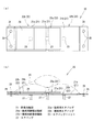
図1は、エアマッサージ機11の一例としてのマット型のエアマッサージ機11aの内部構造を示す一部破断平面図であり、図2はエアマッサージ機11の制御構成を示す説明図である。
An embodiment for carrying out the present invention will be described below with reference to the drawings.
FIG. 1 is a partially broken plan view showing an internal structure of a mat-type
これらの図に示すように、エアマッサージ機11,11aは、エアの供給と排出により膨張収縮する膨張収縮部21が形成された複数のエアバッグ22と、これらのエアバッグ22を載置するマット部31と、このマット部31と前記エアバッグ22を覆う被覆部材41と、前記エアバッグ22に適宜個数設けられた給排気口23に対する給排気を制御する制御部51を有している。
As shown in these drawings, the
前記マット部31は、周知のウレタン等の材料が適宜用いられて、人体Xの全身を寝かせられる大きさの平面視長方形状に形成されている。
The
前記被覆部材41も、周知の適宜の材料が用いられて、前記マット部31を被覆できる大きさに形成されている。
The covering
前記エアバッグ22は、合成樹脂製シートからなる偏平な袋状で、シート状やチューブ状のシートを適宜溶着して構成され、少なくとも1個の前記膨張収縮部21を有する。これらのエアバッグ22は、前記マット部31上の所定位置に配設されている。
The
ここで、前記エアバッグ22には、単独で配設されるものと、組み合わせてエアバッグユニット25として配設されるものがある。
Here, the
単独で配設されるエアバッグ22には周知の適宜のエアバッグを用いる。周知の構成であるので詳しい説明は省略する。エアバッグ22の前記給排気口23にはホース(図示せず)接続されて、エアの供給と排出が行われる。このようなエアバッグ22は、前記マット部31における人体の頭部と両腕部と両脚部に対応する位置に配設されている。
A well-known appropriate airbag is used for the
一方、エアバッグユニット25として配設されるエアバッグ22は、人体Xの背中部と腰部と臀部に対応する位置に配設される。
On the other hand, the
このエアバッグユニット25は、前記マット部31における施術を行う施術位置、すなわち前記人体Xの背中部と腰部と臀部に対応する位置に備えられる施術用膨張収縮部21aと、この施術用膨張収縮部21aの下に備えられ、施術用膨張収縮部21aの平面視位置を規制しつつ施術用膨張収縮部21aを持ち上げる規制用膨張収縮部21bを備える(図2、図3参照)。
This
具体的には、1個の膨張収縮部(施術用膨張収縮部21a又は規制用膨張収縮部21b)を有するエアバッグ(施術用エアバッグ22a又は規制用エアバッグ22b)を3枚用いて一つのエアバッグユニット25が構成されている。
Specifically, three airbags (the
図3は、そのエアバッグユニット25の平面図と正面図で、エアバッグユニット25は、1個の施術用エアバッグ22aの下に、相対向する近接状態で均等に配設された2個の規制用エアバッグ22bを有している。
FIG. 3 is a plan view and a front view of the
規制用エアバッグ22bは、図3(a)に示したように規制用膨張収縮部21bの一側に固定片26を有し、固定片26と反対側の部分を相対向させた状態で近接させて同一平面上に固定されている。規制用膨張収縮部21bの下面の中央には内部の気室に連通する前記給排気口23が形成され、この給排気口23にホース27が接続されている。固定片26の固定はリベット等の適宜の固定手段28で行われる。
As shown in FIG. 3A, the regulating
施術用エアバッグ22aは、施術用膨張収縮部21aの一側に、延設部29を介して固定片26を有し、この固定片26が前記規制用エアバッグ22bの一方と共に固定されている。延設部29は施術用エアバッグ22aを構成するシート材の溶着部分などからなり、延設部29の長さは、図3(b)に仮想線で示したように、前記規制用エアバッグ22bが膨張したときに施術用膨張収縮部21aを膨張前の位置にとどめておける長さである。延設部29は規制用エアバッグ22bの収縮時には適宜折り曲げられたりして偏平な状態を保つように構成されている。
The
延設部29は、図4(a)に示したように内側部分に切欠窓29aを有した構造であってもよく、図4(b)に示したように伸縮可能とすべく複数本のスリット29bを千鳥状に配設した構成であってもよい。前者の場合には規制用エアバッグ22bの収縮時にごわついたり嵩張ったりすることを防げる。後者にあっては、簡易な構成でありながらも柔軟に伸縮可能にすることができる。
As shown in FIG. 4A, the extending
施術用膨張収縮部21aの下面の中央には内部の気室に連通する前記給排気口23が形成され、この給排気口23にホース27が接続されている。このため、前記規制用エアバッグ22b間には、少なくともホース27を通せる隙間が形成されているとよい。
The air supply /
規制用膨張収縮部21bと施術用膨張収縮部21aはいずれも平面視方形に形成され、施術用膨張収縮部21aは規制用膨張収縮部21b上で前後左右に均等に跨るように設置される。図3では、施術用膨張収縮部21aが規制用膨張収縮部21bに収まる大きさの例を示したが、施術用膨張収縮部21aが規制用膨張収縮部21bからはみ出す大きさであってもよい。
The restriction expansion /
また、施術用膨張収縮部21aに接続されるホース27は、図3(b)に仮想線で示したように規制用膨張収縮部21bの膨張に伴って引き出され、収縮に伴って収まるように設けられている。収まるようにするためには、例えばばね等で収まる方向に付勢しておけばよい。
Further, the
前記制御部51は、マイクロコンピュータなどで構成され、図2に示したように、操作パネル52からの入力に従い、かつ、予め記憶させたプログラムに基づいて、エア生成手段53とこのエア生成手段53から送られるエアを分配する分配器54との動作を制御するものである。分配器54には、前述の各エアバッグ22(22a,22b)のホース27が接続されており、ホース27ごとにそれぞれ独立してエアの供給と排出が行えるように構成されている。
The
以上のような構成のエアマッサージ機11では、次のように使用される。操作パネル52から入力操作をすると、制御部51がエア生成手段53と分配器54を駆動制御して、各エアバッグ22(22a,22b)にエアの供給と排出を行って、エアバッグ22(22a,22b)の膨張収縮部21(21a,21b)を膨らましたり縮めたりする。膨張収縮部21(21a,21b)が適宜のパターンで膨張収縮することによって、エアマッサージ機11の上にのる人体Xの各部は制御パターンに応じた、下からの押圧刺激を受ける。
The
このとき、エアバッグユニット25では、次のような動作が行われる。
制御パターンに応じて規制用膨張収縮部21bと施術用膨張収縮部21aはそれぞれ独立して膨張収縮する。膨張には、規制用膨張収縮部21bと施術用膨張収縮部21aが同時に膨張する場合や、規制用膨張収縮部21bが施術用膨張収縮部21aよりも先行して膨張する場合や、規制用膨張収縮部21bが膨張してから施術用膨張収縮部21aが膨張する場合や、施術用膨張収縮部21aが膨張してから規制用膨張収縮部21bが膨張する場合がある。同様に、収縮にも、規制用膨張収縮部21bと施術用膨張収縮部21aが同時に収縮する場合や、規制用膨張収縮部21bが施術用膨張収縮部21aよりも先行して収縮する場合や、規制用膨張収縮部21bが収縮してから施術用膨張収縮部21aが収縮する場合や、施術用膨張収縮部21aが収縮してから規制用膨張収縮部21bが収縮する場合がある。
At this time, the
In accordance with the control pattern, the restricting expansion /
膨張に際して2個の規制用膨張収縮部21bは膨張すると、それらの間に施術用膨張収縮部21aを安定させて、施術用膨張収縮部21aの平面視位置を規制する。同時に、規制用膨張収縮部21bは施術用膨張収縮部21aを上昇させる。
When the two restricting expansion /
一方、施術用膨張収縮部21aは膨張すると、規制用膨張収縮部21bに支えられながら、人体Xの所定の部位を押圧し、施術を行う。規制用膨張収縮部21bが膨張しきった状態で施術用膨張収縮部21aが膨張したときには、膨張高さが最も高くなる。
On the other hand, when the treatment expansion /
膨張時には、施術用膨張収縮部21aのホース27と施術用エアバッグ22aの延設部29と固定片26が、規制用膨張収縮部21bと共に、施術用膨張収縮部21aの位置ずれを抑制する。
At the time of inflation, the
規制用膨張収縮部21bと施術用膨張収縮部21a、又はこれらのうちの一方のエアを排出すると、押圧が解除又は弱められる。収縮に際しても、規制用膨張収縮部21bは施術用膨張収縮部21aの平面視位置を規制する。
When the regulating expansion /
このような膨張収縮動作を、適宜のパターンで繰り返したり、強弱をつけたり、速度を変えたり、他のエアバッグユニット25やエアバッグ22の動作を連動させることによって、様々なバリエーションに富んだ施術ができる。
By repeating such expansion and contraction movements in appropriate patterns, applying strength, changing speed, and linking the movements of
施術は、規制用膨張収縮部21bを膨張させた状態で、施術用膨張収縮部21aのみを膨張収縮させても行える。この場合には、既に膨張している規制用膨張収縮部21bが、これから膨張する施術用膨張収縮部21aをその膨張過程の全体にわたって良好に支える。
The treatment can be performed by inflating and contracting only the treatment inflating / shrinking
このように、施術用膨張収縮部21aは規制用膨張収縮部21bで支えられて、位置ずれが抑制されるので、施術点がずれることはなく、所望の箇所への施術が確実に行える。
In this way, the treatment expansion /
しかも、施術を行う施術用膨張収縮部21aは規制用膨張収縮部21bによって持ち上げられるので、施術用膨張収縮部21aの施術点の上昇高さは、施術用膨張収縮部21a単独の場合よりも高くなる。つまり、膨張収縮ストロークを長く取ることができる。その上、上昇高さが高い割に、厚さ方向に2枚のエアバッグを備えているので、膨張収縮にかかる時間も短く、テンポのよい膨張収縮が可能である。
In addition, since the treatment expansion /
このため、人体Xの背中部や腰部、臀部を持ち上げ、反り返らせるような施術が十分に効果的に行える。 For this reason, the treatment which lifts the back part of the human body X, the waist | hip | lumbar part, and the buttocks, and makes it warp can be performed effectively enough.
また、施術用膨張収縮部21aに対して規制用膨張収縮部21bが均等に配設されているので、安定性が良好であり、施術が確実に行える。
Further, since the regulating expansion /
以下、その他の例を説明する。この説明において先の構成と同一又は同等の部位については同一の符号を付してその詳しい説明を省略する。 Other examples will be described below. In this description, parts that are the same as or equivalent to those in the previous configuration are given the same reference numerals, and detailed descriptions thereof are omitted.
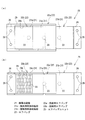
図5は、エアバッグユニット25の他の例を示す平面図と一部断面正面図である。このエアバッグユニット25では、施術用膨張収縮部21aを有する施術用エアバッグ22aの固定片26を、延設部29を介して相反する2辺に設けて、これらを規制用エアバッグ22bが並ぶ方向と直交する方向に向けて固定している。なお、前記固定片26は片方のみに設けられていてもよい。
FIG. 5 is a plan view and a partially sectional front view showing another example of the
このような構成のエアバッグユニット25でも、前述の図3等に示したエアバッグユニット25と同様の作用効果を有する。また、施術用膨張収縮部21aを固定片26により固定する分、より的確に位置規制を行うことができる。
The
図6は、エアバッグユニット25の他の例を示す平面図と一部断面正面図である。このエアバッグユニット25でも、施術用膨張収縮部21aを有する施術用エアバッグ22aの固定片26を、延設部29を介して相反する2辺に設けて、これらを規制用エアバッグ22bが並ぶ方向と直交する方向に向けて固定している。但し、固定片26は、規制用エアバッグ22bの下方に固定されている。つまり、固定片26は規制用エアバッグ22bで覆われている。この場合も、前記固定片26は片方のみに設けられていてもよい。
FIG. 6 is a plan view and a partial cross-sectional front view showing another example of the
このような構成のエアバッグユニット25でも、前述の図3等に示したエアバッグユニット25と同様の作用効果を有する。このほかに、施術用エアバッグ22aを固定する固定手段28を隠蔽できるので、施術を受ける人体Xに対する感覚を良好にする特別の手段を講じる必要性をなくすことができるという効果も有する。
The
また、規制用エアバッグ22bにより固定片26が覆われることにより、固定手段28も規制用エアバッグ22bにより覆われる。これにより、固定手段28が人体Xに直接的または間接的に接触する際の違和感を低減することができるという効果も有する。
Further, since the fixing
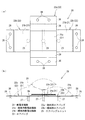
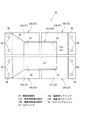
図7は、エアバッグユニット25の他の例を示す平面図である。このエアバッグユニット25では、1個の施術用膨張収縮部21aに対して縦横に配設された4個の規制用膨張収縮部21bを有する例である。すなわち、それぞれ1個ずつの規制用膨張収縮部21bを有する規制用エアバッグ22bを縦横に2個ずつ突き合わせるように近接して配設し、これら規制用エアバッグ22bの規制用膨張収縮部21bの間の中央に中心を合わせるようにして施術用膨張収縮部21aを備えている。施術用膨張収縮部21aを有する施術用エアバッグ22aは、延設部29と固定片26を有する。
FIG. 7 is a plan view showing another example of the
このような構成のエアバッグユニット25では、前述の図3等に示したエアバッグユニット25と同様の作用効果を有するほか、縦横に配設された4個の規制用膨張収縮部21bを有するので、施術用膨張収縮部21aの位置ずれ抑制がより良好に行える。
The
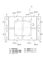
図8は、エアバッグユニット25の他の例を示す平面図である。このエアバッグユニット25は、図7に示したエアバッグユニット25の施術用エアバッグ22aの延設部29と固定片26を省略した構成である。
FIG. 8 is a plan view showing another example of the
このような構成のエアバッグユニット25でも、図7に示したエアバッグユニット25と同様の作用効果を有する。縦横に配設された4個の規制用膨張収縮部21bのために、安定性が良好であるので、部材の小型化等を図ることができる。
The
また、図8の例では、施術用エアバッグ22aの延設部29と固定片26とを省略しているので、固定片26に設けられる固定手段28が人体Xに直接的または間接的に接触することがない。これにより、固定片26に固定手段28が設けられる場合とは異なり、固定片26に起因する違和感をなくすことができるという効果も有する。
Further, in the example of FIG. 8, the extending
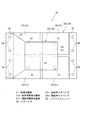
図9は、エアバッグユニット25の他の例を示す平面図である。このエアバッグユニット25は、図7に示したエアバッグユニット25の4個の規制用膨張収縮部21bを1枚の規制用エアバッグ22bに備えた構成である。このような規制用エアバッグ22bは、上下2枚のシート部を部分的に相互に溶着して方形状をなす4個の規制用膨張収縮部21bに区切って製造される。この規制用エアバッグ22bは、各規制用膨張収縮部21b間に膨張のための余裕を持たせて固定される。
FIG. 9 is a plan view showing another example of the
このような構成のエアバッグユニット25でも、図7に示したエアバッグユニット25と同様の作用効果を有する。
The
また、4個の規制用膨張収縮部21bの位置を、固定手段28により、より正確に決めることができるので、各規制用膨張収縮部21bの位置が正確に決まる分、施術用膨張収縮部21aの位置決めも、より正確に行うことができるという作用効果を有する。
Further, since the positions of the four restricting expansion /
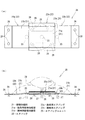
図10は、他の例に係るマット型のエアマッサージ機11aの内部構造を示す一部破断平面図である。このエアマッサージ機11aは、人体Xを支えられる大きさで複数の膨張収縮部21を有した1枚のエアバッグ22の上に、施術用エアバッグ22aを備えた例を示している。施術用エアバッグ22aには、施術用膨張収縮部21aを1個有するものと複数有するものがある。
FIG. 10 is a partially broken plan view showing an internal structure of a mat-type
すなわち、前記1枚のエアバッグ22のうち施術用エアバッグ22aの施術用膨張収縮部21aを支える部分にある膨張収縮部21が規制用膨張収縮部21bである。そして、前記1枚のエアバッグ22のうち規制用膨張収縮部21b以外の膨張収縮部21が、施術を行う膨張収縮部である。
That is, the inflation /
このような構成のエアバッグユニット25でも、前述の図3等、図7等に示したエアバッグユニット25を用いた場合と同様の作用効果を有する。このほか、図10のマット型のエアマッサージ機11aでは、規制用膨張収縮部21bや施術用膨張収縮部21aを1枚のエアバッグに複数備えているので、取り付けるエアバッグ22,22aの枚数を少なくできる。このため、マット部31に対するエアバッグ22,22aの取り付け作業が、多数のエアバッグを個々に取り付ける場合に比して容易で作業性がよいという利点を有する。
The
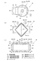
図11は、エアバッグユニット25の他の例を示す平面図である。このうち図11(a)のエアバッグユニット25は、1個の施術用膨張収縮部21aに対して1個の規制用膨張収縮部21bを備えた構成である。すなわち、前述の構成と同様の施術用膨張収縮部21aの下に、穴あきドーナツ状に膨張する規制用膨張収縮部21bを有する規制用エアバッグ22bを備えている。図11(a)中、61は中心穴で、62は溶着部分で、63は放射状に形成された切り込みである。この切り込み63は、規制用膨張収縮部21bを膨張しやすくする。
FIG. 11 is a plan view showing another example of the
この構成では、前述のような効果を有するほか、規制用膨張収縮部21bは穴あきドーナツ状であり、その中央の中心穴61部分に施術用膨張収縮部21aの中央が存在するので、規制用膨張収縮部21bが1個であっても、施術用膨張収縮部21a位置ずれ防止と持ち上げができるという効果も有する。
In this configuration, in addition to the above-described effects, the restricting expansion /
図11(b)のエアバッグユニット25は、規制用膨張収縮部21bを平面視直角三角形に形成し、このような規制用膨張収縮部21bを有する2枚の規制用エアバッグ22bを規制用膨張収縮部21bの直角に対向する長辺部分同士が近接した状態で配置され、その上に施術用膨張収縮部21aを有する施術用エアバッグ22aを備えた構成である。
In the
この構成では、前述のような効果を有するほか、規制用膨張収縮部21bは前記長辺部分が最も高く膨張するので、エアバッグユニット25全体の膨張高さを更に高くすることができるという効果を有する。
In this configuration, in addition to the above-described effects, since the long side portion of the regulating inflating / shrinking
図11(c)のエアバッグユニット25は、1個の施術用膨張収縮部21aを複数の規制用膨張収縮部21bで支持する構成であるが、規制用膨張収縮部21bは、相対向する近接状態で均等に配設するのではなく、施術用膨張収縮部21aの下に施術用膨張収縮部21aの長手方向に沿って一列に並べて設けた構成である。図11(c)において横長の長方形に形成された施術用膨張収縮部21aは長手方向の両側に固定片26が設けられて、縦長の長方形に形成された規制用膨張収縮部21bも長手方向の両側に固定片が設けられて、これらが直交するように固定されている。
The
この構成では、前述のような効果を有するほか、施術のバリエーションを増やせるという効果を有する。つまり、規制用膨張収縮部21bの膨張収縮において、施術用膨張収縮部21aの平面視位置を規制しつつ持ち上げる作用のほかに、規制用膨張収縮部21bの膨張収縮のタイミングを適宜ずらすことによって、間接的に施術を行う作用や、押圧面を広げる作用を付加することができる。
In addition to the effects described above, this configuration has the effect of increasing variations in treatment. In other words, in the expansion and contraction of the restricting expansion /
間接的な施術のためには、例えば複数の規制用膨張収縮部21bを端から順に波が伝播するように膨張収縮させたり、特定の規制用膨張収縮部21bのみを膨張収縮させたりするとよい。押圧面の拡大のためには、膨張高さが低くなりがちな施術用膨張収縮部21aの長手方向の両端部に位置する規制用膨張収縮部21bをその他の規制用膨張収縮部21bより大きくしたり、大きく膨張させたりするとよい。
For indirect treatment, for example, a plurality of restricting expansion /
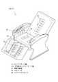
図12は、エアマッサージ機11の一例としての椅子型のエアマッサージ機11bの斜視図である。このエアマッサージ機11aは、背凭れ部、座部、座部両側の側壁、アームレスト、足のせ部の各部に、前述のようなエアバッグユニット25が適宜備えられた構成である。
FIG. 12 is a perspective view of a chair-type
このような構成のエアマッサージ機11bでも、前述のような作用効果が得られる。エアバッグユニット25の膨張高さが高いので、人体の背中や肩は勿論のこと、特に腕や大腿部の側面と下面、臀部、足裏に対する施術に効果的である。
Even with the
この発明の構成と前述の構成との対応において、
この発明の膨張収縮部は、膨張収縮部21、施術用膨張収縮部21a、規制用膨張収縮部21bに対応し、
同様に、
エアバッグは、エアバッグ22、施術用エアバッグ22a、規制用エアバッグ22bに対応するも、
この発明は前述の構成のみに限定されるものではなく、その他の形態を採用することができる。
In correspondence between the configuration of the present invention and the above-described configuration,
The expansion / contraction part of the present invention corresponds to the expansion /
Similarly,
The airbag corresponds to the
The present invention is not limited to the above-described configuration, and other forms can be adopted.
例えば、規制用膨張収縮部は上下に複数備えることもできる。 For example, a plurality of restricting expansion / contraction portions can be provided in the vertical direction.
また、前述のようなマッサージユニットを備えたエアマッサージ機は、例えば人体の局部を施術する小型のマッサージ機などであってもよい。 Moreover, the air massage machine provided with the massage unit as described above may be, for example, a small massage machine for operating a local part of a human body.
11…エアマッサージ機
11a…マット型のエアマッサージ機
11b…椅子型のエアマッサージ機
21…膨張収縮部
21a…施術用膨張収縮部
21b…規制用膨張収縮部
22…エアバッグ
22a…施術用エアバッグ
22b…規制用エアバッグ
25…エアバッグユニット
DESCRIPTION OF
Claims (4)
施術を行う施術位置に備えられる施術用膨張収縮部の下に、該施術用膨張収縮部の平面視位置を規制しつつ前記施術用膨張収縮部を持ち上げる規制用膨張収縮部を備えたエアバッグユニットを有する
エアマッサージ機。 An air massage machine including an airbag formed with an inflating and contracting part that inflates and contracts by supplying and discharging air,
An airbag unit including a restriction inflation / deflation part that lifts the treatment inflation / deflation part under a treatment inflation / deflection part provided at a treatment position for performing a treatment while regulating the planar view position of the treatment inflation / deflation part Having air massage machine.
請求項1に記載のエアマッサージ機。 2. The airbag unit according to claim 1, wherein the airbag unit includes a plurality of the restricting inflating and shrinking portions that are equally disposed in close proximity to each other with respect to one of the treatment inflating and shrinking portions. Air massage machine.
請求項1または請求項2に記載のエアマッサージ機。 The air massage machine according to claim 1 or 2, wherein the airbag unit has two of the restricting inflating and shrinking parts with respect to one of the treatment inflating and shrinking parts.
請求項1または請求項2に記載のエアマッサージ機。 3. The air massage machine according to claim 1, wherein the airbag unit has the four restricting inflating and shrinking portions arranged vertically and horizontally with respect to one of the treatment inflating and shrinking portions. 4. .
Priority Applications (1)
| Application Number | Priority Date | Filing Date | Title |
|---|---|---|---|
| JP2012094603A JP6013010B2 (en) | 2012-04-18 | 2012-04-18 | Air massage machine |
Applications Claiming Priority (1)
| Application Number | Priority Date | Filing Date | Title |
|---|---|---|---|
| JP2012094603A JP6013010B2 (en) | 2012-04-18 | 2012-04-18 | Air massage machine |
Publications (2)
| Publication Number | Publication Date |
|---|---|
| JP2013220249A true JP2013220249A (en) | 2013-10-28 |
| JP6013010B2 JP6013010B2 (en) | 2016-10-25 |
Family
ID=49591657
Family Applications (1)
| Application Number | Title | Priority Date | Filing Date |
|---|---|---|---|
| JP2012094603A Active JP6013010B2 (en) | 2012-04-18 | 2012-04-18 | Air massage machine |
Country Status (1)
| Country | Link |
|---|---|
| JP (1) | JP6013010B2 (en) |
Citations (4)
| Publication number | Priority date | Publication date | Assignee | Title |
|---|---|---|---|---|
| JPH1133067A (en) * | 1997-07-18 | 1999-02-09 | Advance Co Ltd | Stimulating device |
| JP2001104421A (en) * | 1999-10-08 | 2001-04-17 | Toshiba Tec Corp | Air massager |
| JP2003210540A (en) * | 2002-01-18 | 2003-07-29 | Toshiba Tec Corp | Massage machine |
| JP2007061177A (en) * | 2005-08-29 | 2007-03-15 | Toshiba Tec Corp | Massage machine |
-
2012
- 2012-04-18 JP JP2012094603A patent/JP6013010B2/en active Active
Patent Citations (4)
| Publication number | Priority date | Publication date | Assignee | Title |
|---|---|---|---|---|
| JPH1133067A (en) * | 1997-07-18 | 1999-02-09 | Advance Co Ltd | Stimulating device |
| JP2001104421A (en) * | 1999-10-08 | 2001-04-17 | Toshiba Tec Corp | Air massager |
| JP2003210540A (en) * | 2002-01-18 | 2003-07-29 | Toshiba Tec Corp | Massage machine |
| JP2007061177A (en) * | 2005-08-29 | 2007-03-15 | Toshiba Tec Corp | Massage machine |
Also Published As
| Publication number | Publication date |
|---|---|
| JP6013010B2 (en) | 2016-10-25 |
Similar Documents
| Publication | Publication Date | Title |
|---|---|---|
| JP3192853U (en) | Stretch assist device | |
| CN108685664B (en) | Leg placement unit and massage machine provided with same | |
| JP5890725B2 (en) | Seated massage device | |
| JPH11347082A (en) | Air massager | |
| JP5628551B2 (en) | Massage machine | |
| JP6752028B2 (en) | Massage machine | |
| JP5828261B2 (en) | Massage machine | |
| JP2012045131A (en) | Massage air bag and massage machine | |
| JP6260244B2 (en) | Sheet device | |
| JP6712352B1 (en) | Vehicle seat | |
| JP2002065779A (en) | Air massage machine | |
| JP6013010B2 (en) | Air massage machine | |
| JP3903077B2 (en) | Massage machine | |
| JP2018171284A (en) | Ottoman and massage machine comprising the same | |
| JP4123871B2 (en) | Air massage device and chair type massage machine equipped with air massage device | |
| JP6712351B1 (en) | Vehicle seat | |
| JP2000051302A (en) | Massage machine | |
| JP6387033B2 (en) | Massage machine | |
| JP5557944B2 (en) | Massage machine | |
| JP5236792B2 (en) | Massage machine | |
| JP5828262B2 (en) | Massage machine | |
| JP5147747B2 (en) | Chair type stretching machine | |
| JP5896864B2 (en) | Massage machine | |
| JP2011130812A (en) | Massage machine | |
| JP2011239824A (en) | Body exercise equipment |
Legal Events
| Date | Code | Title | Description |
|---|---|---|---|
| A621 | Written request for application examination |
Free format text: JAPANESE INTERMEDIATE CODE: A621 Effective date: 20150220 |
|
| A977 | Report on retrieval |
Free format text: JAPANESE INTERMEDIATE CODE: A971007 Effective date: 20151218 |
|
| A131 | Notification of reasons for refusal |
Free format text: JAPANESE INTERMEDIATE CODE: A131 Effective date: 20151222 |
|
| A521 | Request for written amendment filed |
Free format text: JAPANESE INTERMEDIATE CODE: A523 Effective date: 20160219 |
|
| A131 | Notification of reasons for refusal |
Free format text: JAPANESE INTERMEDIATE CODE: A131 Effective date: 20160510 |
|
| A521 | Request for written amendment filed |
Free format text: JAPANESE INTERMEDIATE CODE: A523 Effective date: 20160610 |
|
| A131 | Notification of reasons for refusal |
Free format text: JAPANESE INTERMEDIATE CODE: A131 Effective date: 20160802 |
|
| A521 | Request for written amendment filed |
Free format text: JAPANESE INTERMEDIATE CODE: A523 Effective date: 20160810 |
|
| TRDD | Decision of grant or rejection written | ||
| A01 | Written decision to grant a patent or to grant a registration (utility model) |
Free format text: JAPANESE INTERMEDIATE CODE: A01 Effective date: 20160830 |
|
| A61 | First payment of annual fees (during grant procedure) |
Free format text: JAPANESE INTERMEDIATE CODE: A61 Effective date: 20160921 |
|
| R150 | Certificate of patent or registration of utility model |
Ref document number: 6013010 Country of ref document: JP Free format text: JAPANESE INTERMEDIATE CODE: R150 |
|
| RD03 | Notification of appointment of power of attorney |
Free format text: JAPANESE INTERMEDIATE CODE: A7423 Effective date: 20171020 |
|
| RD03 | Notification of appointment of power of attorney |
Free format text: JAPANESE INTERMEDIATE CODE: R3D03 |
|
| R250 | Receipt of annual fees |
Free format text: JAPANESE INTERMEDIATE CODE: R250 |
|
| R250 | Receipt of annual fees |
Free format text: JAPANESE INTERMEDIATE CODE: R250 |
|
| R250 | Receipt of annual fees |
Free format text: JAPANESE INTERMEDIATE CODE: R250 |
|
| R250 | Receipt of annual fees |
Free format text: JAPANESE INTERMEDIATE CODE: R250 |
|
| R250 | Receipt of annual fees |
Free format text: JAPANESE INTERMEDIATE CODE: R250 |
|
| R250 | Receipt of annual fees |
Free format text: JAPANESE INTERMEDIATE CODE: R250 |
|
| R250 | Receipt of annual fees |
Free format text: JAPANESE INTERMEDIATE CODE: R250 |