JP2013217455A - Rolling bearing device for vehicle - Google Patents
Rolling bearing device for vehicle Download PDFInfo
- Publication number
- JP2013217455A JP2013217455A JP2012089142A JP2012089142A JP2013217455A JP 2013217455 A JP2013217455 A JP 2013217455A JP 2012089142 A JP2012089142 A JP 2012089142A JP 2012089142 A JP2012089142 A JP 2012089142A JP 2013217455 A JP2013217455 A JP 2013217455A
- Authority
- JP
- Japan
- Prior art keywords
- lip
- inner ring
- outer peripheral
- seal member
- bearing device
- Prior art date
- Legal status (The legal status is an assumption and is not a legal conclusion. Google has not performed a legal analysis and makes no representation as to the accuracy of the status listed.)
- Pending
Links
Images
Abstract
Description
この発明は車両用転がり軸受装置に関する。 The present invention relates to a rolling bearing device for a vehicle.
従来より、自動車などの車輪を取付けることのできる車輪側フランジ部を一体に形成したハブ軸の軸部が転がり軸受を介して支持体に支承される車輪のハブ軸用軸受装置(車輪用ハブユニット)が知られている。車輪のハブ軸用軸受装置における軸受の一般的な構成は、車輪を取付けることのできるフランジ部を一体に形成したハブ軸の軸部を有する内輪と、内輪と同芯且つこの内輪の外周側に配設される外輪と、内輪と外輪との間の環状空間に転動可能に配設される転動体とを備えている。
この内輪は、転動体を介することで外輪に対し回転自在な構成である。そのため、内輪のフランジ部側面と外輪の間が接触しないように隙間を設ける必要がある。そこで、かかる隙間に泥水が浸入するのを防ぐために内外輪間の環状空間のうちフランジ部側の開口部を密封する密封装置を備えている。ところが、被水環境が厳しい条件においては、密封装置への泥水の浸入が著しいため密封装置のリップ部材が早期に磨耗してしまう。このリップ部材の早期磨耗が進捗すると泥水が密封装置を通過して軸受内に浸入してさび等の腐食を招いて軸受が損傷するおそれがあった。
これに対し、特許文献1のような密封装置が知られている。図示を省略するが、特許文献1に開示されている内容は、金属環と弾性体で形成され外輪に固定されたシール体と、金属製で形成され内輪に固定される環状部材が軸方向から組み合わせて弾性体を挟み込む構成の密封装置である。このシール体及び環状部材は、それぞれが径方向に屈曲した形状とされており、これらが軸方向から組み合わされることでラビリンス部を構成している。これにより、泥水の浸入を抑制している。
Conventionally, a hub shaft bearing device (wheel hub unit for a wheel) in which a shaft portion of a hub shaft integrally formed with a wheel side flange portion to which a wheel of an automobile or the like can be mounted is supported on a support via a rolling bearing. )It has been known. The general configuration of the bearing in the wheel hub shaft bearing device is as follows: an inner ring having a shaft portion of a hub shaft integrally formed with a flange portion to which a wheel can be attached, a concentric inner ring and an outer peripheral side of the inner ring. An outer ring to be disposed and a rolling element disposed to be able to roll in an annular space between the inner ring and the outer ring are provided.
The inner ring is configured to be rotatable with respect to the outer ring through a rolling element. Therefore, it is necessary to provide a gap so that the side surface of the flange portion of the inner ring does not contact the outer ring. Therefore, in order to prevent muddy water from entering the gap, a sealing device for sealing the opening on the flange side in the annular space between the inner and outer rings is provided. However, under conditions where the wet environment is severe, the infiltration of muddy water into the sealing device is remarkable, so that the lip member of the sealing device is worn early. If the early wear of the lip member progresses, the muddy water may pass through the sealing device and enter the bearing to cause corrosion such as rust and damage the bearing.
On the other hand, a sealing device like patent document 1 is known. Although not shown in the drawings, the content disclosed in Patent Document 1 includes a seal body formed of a metal ring and an elastic body and fixed to an outer ring, and an annular member formed of metal and fixed to an inner ring from the axial direction. It is a sealing device configured to sandwich an elastic body in combination. Each of the seal body and the annular member has a shape bent in the radial direction, and the labyrinth portion is configured by combining them in the axial direction. Thereby, infiltration of muddy water is suppressed.
しかしながら、上記特許文献1における密封装置に設けられたラビリンス部は、一度浸入した泥水の排出が困難である。そのため、内輪のフランジ部側面と外輪の間の隙間は、被水環境が厳しい条件において密封装置への泥水の浸入が著しい場合、依然としてリップ部材の早期磨耗や軸受内の腐食等の問題が払拭されていない。また、上記特許文献1における環状部材の大部分は、フランジ部から離間した位置に配設される構成であるため泥水が直接的に浸入し難い。しかしながら、環状部材は回転する内輪側に固定されている。そのため、内輪の高速回転等によって変形してしまうとシール体との密封性能が低下するおそれがある。 However, it is difficult for the labyrinth portion provided in the sealing device in Patent Document 1 to discharge muddy water once entered. For this reason, the gap between the side surface of the flange portion of the inner ring and the outer ring is still free from problems such as premature wear of the lip member and corrosion in the bearing when muddy water enters the sealing device under severe water conditions. Not. Moreover, since most of the annular members in Patent Document 1 are arranged at positions separated from the flange portion, it is difficult for muddy water to enter directly. However, the annular member is fixed to the rotating inner ring side. Therefore, if the inner ring is deformed by high-speed rotation or the like, the sealing performance with the sealing body may be deteriorated.
而して、本発明は、このような点に鑑みて創案されたものであり、本発明が解決しようとする課題は、車両用転がり軸受装置の内輪と外輪との間の環状空間のうちフランジ部側の開口部の泥水の浸入を抑制して耐泥水性向上を図ることにある。 Thus, the present invention was devised in view of such a point, and the problem to be solved by the present invention is that a flange in an annular space between an inner ring and an outer ring of a rolling bearing device for a vehicle. The purpose is to improve the muddy water resistance by suppressing the intrusion of muddy water in the opening on the part side.
上記課題を解決するために、本発明の車両用転がり軸受装置は次の手段をとる。
先ず、第1の発明に係る車両用転がり軸受装置は、車輪を取付けることのできるフランジ部を一体に形成したハブ軸の軸部を有する内輪と、該内輪と同芯且つ該内輪の外周側に配設される外輪と、前記内輪と前記外輪との間の環状空間に転動可能に配設される転動体と、前記環状空間の前記フランジ部側の開口部を密封する密封装置を備えた車両用転がり軸受装置であって、前記密封装置は、第1シール部材と第2シール部材を備えており、前記第1シール部材は、前記外輪に圧入される第1円筒部と該第1円筒部の一端から径方向内方又は径方向外方に延出する第1環状部とを有する第1芯金と、該第1芯金から前記内輪側に向かって延出する第1リップと、前記第1芯金の外周端縁から前記外輪まで回り込んで設けられる弾性体からなる第1防水部材とを有しており、前記第2シール部材は、前記内輪に圧入される第2円筒部と該第2円筒部の一端から径方向外方に延出する第2環状部とを有する第2芯金と、該第2芯金の外周端縁から前記第1芯金側に向かって延出する第2リップと、前記第2芯金の外周端縁から前記内輪まで回り込んで設けられる弾性体からなる第2防水部材とを有し、前記第1シール部材の第1リップは、前記第2芯金の外周面に摺接して前記開口部を密封し、前記第2シール部材の第2リップは、前記第1芯金に摺接して前記開口部を密封することを特徴とする。
In order to solve the above problems, the rolling bearing device for a vehicle of the present invention takes the following means.
First, a rolling bearing device for a vehicle according to a first aspect of the present invention includes an inner ring having a shaft portion of a hub shaft integrally formed with a flange portion to which a wheel can be attached, a concentric core with the inner ring, and an outer peripheral side of the inner ring. An outer ring to be disposed; a rolling element disposed to be able to roll in an annular space between the inner ring and the outer ring; and a sealing device for sealing an opening on the flange portion side of the annular space. A rolling bearing device for a vehicle, wherein the sealing device includes a first seal member and a second seal member, and the first seal member is press-fitted into the outer ring and the first cylinder. A first cored bar having a first annular part extending radially inward or radially outward from one end of the part; a first lip extending from the first cored bar toward the inner ring side; It consists of an elastic body provided around the outer peripheral edge of the first cored bar to the outer ring. The second sealing member includes a second cylindrical portion press-fitted into the inner ring, and a second annular portion extending radially outward from one end of the second cylindrical portion. A second metal core having a second metal core, a second lip extending from the outer peripheral edge of the second metal core toward the first metal core, and a loop from the outer peripheral edge of the second metal core to the inner ring. A second waterproof member made of an elastic body, and a first lip of the first seal member is in sliding contact with an outer peripheral surface of the second core metal to seal the opening, and the second seal member The second lip is slidably contacted with the first mandrel to seal the opening.
この第1の発明によれば、第1シール部材の第1リップは、第2シール部材の第2芯金の外周面に摺接して開口部を密封し、第2シール部材の第2リップは、第1シール部材の第1芯金に摺接して開口部を密封する。即ち、第1シール部材と第2シール部材は、それぞれリップを有しており、互いの芯金に摺接することで開口部を密封する。また、第1シール部材は、第1防水部材が圧入する外輪まで回り込んで設けられている。また、第2シール部材は、第2防水部材が圧入するハブ軸のフランジ部の側面まで回り込んで設けられている。そのため、第1シール部材と第2シール部材は、圧入される部材との間の泥水の浸入を防止しさび等の腐食を防ぐことができる。これにより、車両用転がり軸受装置の内輪と外輪との間の環状空間のうちフランジ部側の開口部の泥水の浸入を抑制して耐泥水性向上を図ることができる。 According to the first aspect of the invention, the first lip of the first seal member is in sliding contact with the outer peripheral surface of the second core metal of the second seal member to seal the opening, and the second lip of the second seal member is The opening is sealed by sliding contact with the first cored bar of the first seal member. That is, each of the first seal member and the second seal member has a lip, and seals the opening by sliding contact with each other. The first seal member is provided so as to go around to the outer ring into which the first waterproof member is press-fitted. Further, the second seal member is provided so as to go around to the side surface of the flange portion of the hub shaft into which the second waterproof member is press-fitted. Therefore, the first seal member and the second seal member can prevent muddy water from entering between the press-fitted members and prevent corrosion such as rust. Thereby, intrusion of muddy water in the opening on the flange portion side in the annular space between the inner ring and the outer ring of the rolling bearing device for the vehicle can be suppressed, and the muddy water resistance can be improved.
次に、第2の発明に係る車両用転がり軸受装置は、上述した第1の発明において、前記第2リップは、前記第2芯金の外周端縁から第1芯金に傾斜して摺接する構成とされており、前記第2リップは、前記内輪の回転に伴う遠心力作用によって、前記第2リップと第1芯金の摺接が離れる傾斜方向に配設されていることを特徴とする。 Next, in the rolling bearing device for a vehicle according to the second invention, in the first invention described above, the second lip is inclined and slidably contacted from the outer peripheral edge of the second metal core to the first metal core. The second lip is arranged in an inclined direction in which the sliding contact between the second lip and the first metal core is separated by the centrifugal force action accompanying the rotation of the inner ring. .
この第2の発明によれば、第2リップは、第2芯金の外周端縁から第1芯金に傾斜して摺接する構成である。そして、第2リップは、内輪の回転に伴う遠心力作用によって、第2リップと第1芯金の当接が離れる傾斜方向に配設されている。これは、内輪のフランジ部側面と外輪の間の開口部を塞ぐような接触タイプのシール部材を追加することで耐泥水性向上を図ることが考えられる。しかし、第2リップが常に第1芯金と接触した構成では、トルクが増加するおそれがあるという懸念が新たに生じる。
そこで、上記構成を採用することにより、内輪が低速回転時の状態では、内輪のフランジ部側面と外輪の間の開口部に泥水が浸入しやすいため第2リップの先端が第1芯金に摺動する。一方、内輪が高速回転時では、内輪の回転に伴う遠心力作用によって第2リップの先端が第1芯金から離れて非接触となる。これにより、車両用転がり軸受装置の高速回転時のトルクの増加を最小限に抑制できる。また、内輪の高速回転の状況下では、遠心力作用によって第2リップの先端が第1芯金から離間するに至り、それに伴い、この隙間から泥水が浸入またはこの隙間に滞留したとしても、この泥水にも遠心力が作用することにより外周側に吹き飛ばされるから、結果的に泥水が浸入しにくくなる(浸入しても迅速に排出される)。加えて少なくとも高速回転時には、第2リップが非接触状態を保持できるため、その磨耗も抑制することができる。また高速回転状況下では、第2リップと第1芯金とは非接触であるため、摺動トルクを低減できることは言うまでもない。
そのため、第2リップの先端が非接触状態でも耐泥水性は低下しない。これにより、車両用転がり軸受装置のトルクの増加を最小限に抑制しつつ耐泥水性向上を図ることができる。
According to the second aspect of the invention, the second lip is configured to be in sliding contact with the first cored bar inclined from the outer peripheral edge of the second cored bar. And the 2nd lip is arrange | positioned in the inclination direction from which contact | abutting of a 2nd lip and a 1st metal core leaves | separates by the centrifugal force effect | action accompanying rotation of an inner ring | wheel. It is conceivable to improve the mud water resistance by adding a contact type seal member that closes the opening between the flange side surface of the inner ring and the outer ring. However, in the configuration in which the second lip is always in contact with the first mandrel, there is a new concern that the torque may increase.
Therefore, by adopting the above configuration, when the inner ring is rotating at a low speed, muddy water easily enters the opening between the flange side surface of the inner ring and the outer ring, so that the tip of the second lip slides on the first core bar. Move. On the other hand, when the inner ring rotates at a high speed, the distal end of the second lip is separated from the first core bar and is not in contact with the centrifugal force due to the rotation of the inner ring. Thereby, the increase in the torque at the time of high-speed rotation of the rolling bearing device for vehicles can be suppressed to the minimum. Further, under the condition of the inner ring rotating at a high speed, even if the tip of the second lip is separated from the first core due to the centrifugal force action, even if muddy water enters or stays in this gap, Since centrifugal force acts on the muddy water, the muddy water is blown off to the outer peripheral side. As a result, the muddy water is difficult to enter (even if it enters, it is quickly discharged). In addition, since the second lip can maintain a non-contact state at least during high-speed rotation, wear can be suppressed. Needless to say, the sliding torque can be reduced because the second lip and the first metal core are not in contact with each other under high-speed rotation conditions.
Therefore, even if the tip of the second lip is not in contact, the muddy water resistance does not decrease. Thereby, it is possible to improve the muddy water resistance while suppressing an increase in torque of the rolling bearing device for a vehicle to a minimum.
次に、第3の発明に係る車両用転がり軸受装置は、上述した第1の発明又は第2の発明において、前記第2シール部材の第2リップと、第2防水部材は、一体に形成されていることを特徴とする。 Next, in the rolling bearing device for a vehicle according to the third invention, in the first invention or the second invention described above, the second lip of the second seal member and the second waterproof member are integrally formed. It is characterized by.
この第3の発明によれば、第2シール部材の第2リップと、第2防水部材は、一体に形成することにより材料コスト、製造コストの抑制を図ることができる。 According to the third aspect of the present invention, the second lip of the second seal member and the second waterproof member are integrally formed, so that material costs and manufacturing costs can be suppressed.
次に、第4の発明に係る車両用転がり軸受装置は、上述した第1の発明から第3の発明のいずれかにおいて、前記第1芯金の第1円筒部は、外輪の外周側に配設されており、前記第1円筒部の内周面が前記外輪の外周面に圧入される構成であることを特徴とする。 Next, in a rolling bearing device for a vehicle according to a fourth aspect of the present invention, in any one of the first to third aspects described above, the first cylindrical portion of the first cored bar is arranged on the outer peripheral side of the outer ring. It is provided, It is the structure which press-fits the inner peripheral surface of the said 1st cylindrical part to the outer peripheral surface of the said outer ring | wheel.
この第4の発明によれば、第1芯金の第1円筒部は、外輪の外周側に配設され、第1円筒部の内周面が外輪の外周面に圧入される構成である。これにより、第1芯金の第1防水部材が外輪外周面に配設されることとなる。これにより、第1防水部材は、外輪外周面上の泥水を開口部に流下する手前で阻止する構成となり、耐泥水性向上を図ることができる。 According to the fourth aspect of the invention, the first cylindrical portion of the first metal core is disposed on the outer peripheral side of the outer ring, and the inner peripheral surface of the first cylindrical portion is press-fitted into the outer peripheral surface of the outer ring. Thereby, the 1st waterproofing member of the 1st metal core will be arranged on the outer ring outer peripheral surface. Thereby, a 1st waterproof member becomes a structure which blocks | prevents the muddy water on an outer ring outer peripheral surface before flowing down to an opening part, and can aim at a muddy water resistance improvement.
本発明は上記各発明の手段をとることにより、車両用転がり軸受装置の内輪と外輪との間の環状空間のうちフランジ部側の開口部の泥水の浸入を抑制して耐泥水性向上を図ることができる。 By taking the measures of the above inventions, the present invention suppresses the intrusion of muddy water in the opening on the flange side in the annular space between the inner ring and the outer ring of the rolling bearing device for a vehicle, thereby improving the mud water resistance. be able to.
[実施形態1]
本発明の実施形態1を図1から図3にしたがって説明する。なお、本発明の車両用転がり軸受装置を説明するにあたり、自動車などの車輪を取付けることのできる車輪側フランジ部を一体に形成したハブ軸の軸部が転がり軸受を介して支持体に支承される車輪のハブ軸用軸受装置(車輪用ハブユニット)を用いて説明する。
[Embodiment 1]
A first embodiment of the present invention will be described with reference to FIGS. In describing the rolling bearing device for a vehicle according to the present invention, a shaft portion of a hub shaft integrally formed with a wheel side flange portion to which a wheel of an automobile or the like can be attached is supported on a support via the rolling bearing. Description will be made using a wheel hub shaft bearing device (wheel hub unit).
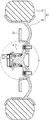
車輪60のハブ軸用軸受装置A(車両用転がり軸受装置)は、図1に図示されるように車両に構成される懸架装置(図示省略)に支持されると共に、ブレーキロータ55を介して車輪60を回転可能に支持するものである。車輪60には、タイヤ62及びホイール64が構成される。図2に図示されるように、車輪用ハブユニットとしての車輪60のハブ軸用軸受装置Aは、車輪60(図1参照)を取付けることのできる車輪側フランジ部21を一体に形成したハブ軸1が、軸受としての複列のアンギュラ玉軸受41とを一体状に有してユニット化されている。車輪60のハブ軸用軸受装置Aは、アンギュラ玉軸受41を介して、図示を省略する車両の懸架装置に支持されたナックルに支承されている。
A hub shaft bearing device A (vehicle rolling bearing device) of the
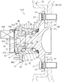
車輪60(図1参照)のハブ軸用軸受装置Aの基本的な構成は、図2に図示されるようにハブ軸1(内輪)と、内輪形成環状部材42(内輪)と、外輪部材45(外輪)と、玉50、51(転動体)と保持器52、53と、密封装置70を主体として構成される。ハブ軸1と、内輪形成環状部材42と、外輪部材45と、玉50、51は金属製で構成されている。保持器52、53は、合成樹脂製で構成されている。このうち軸受としての複列のアンギュラ玉軸受41は、ハブ軸1と内輪形成環状部材42のそれぞれ外周面に構成される内輪軌道面18、44と、外輪部材45の内周面に構成される外輪軌道面46、47と、玉50、51と、保持器52、53を主体として構成される。
As shown in FIG. 2, the basic configuration of the hub shaft bearing device A for the wheel 60 (see FIG. 1) is the hub shaft 1 (inner ring), the inner ring forming annular member 42 (inner ring), and the
ハブ軸1は、図2に図示されるように軸部10と、嵌合軸部30と、フランジ基部23と、車輪側フランジ部21(フランジ部)を一体に有する。
As shown in FIG. 2, the hub shaft 1 integrally includes a
軸部10は、図2及び図3に図示されるようにアンギュラ玉軸受41が組み付けられる部位である。軸部10は、後述する車輪側フランジ部21側から先端側に向けて段軸状に形成されている。軸部10の車輪側フランジ部21側には、大径の大径部11が形成される。軸部10の先端側には、小径の小径部12が形成される。軸部10の大径部11の外周面には、転がり軸受としての複列のアンギュラ玉軸受41の一方の内輪軌道面18が形成される。内輪軌道面18の肩部と車輪側フランジ部21の隅部19は、周方向に滑らかな曲面状に形成されている。軸部10の小径部12の外周面は、後述する内輪形成環状部材42が嵌め込まれる部位である。さらに、軸部10の先端部には、小径部12と同径の端軸部15が延出されている。端軸部15の端面中心部には軸端凹部16が形成されている。
嵌合軸部30は、図2に図示されるように軸部10の一端側に形成されかつ、軸部10よりも大径で車輪60の中心孔が嵌込まれる部位である。嵌合軸部30には、車輪側フランジ部21側にブレーキロータ55に対応するブレーキロータ用嵌合部31が形成され、先端側にブレーキロータ用嵌合部31よりも若干小径で車輪60(図1参照)に対応する車輪用嵌合部32が形成されている。
フランジ基部23は、図2に図示されるように軸部10と嵌合軸部30との間に位置し、車輪側フランジ部21の基部として構成される部位である。車輪側フランジ部21は、このフランジ基部23の外周面に外径方向へ放射状に延出された部位である。車輪側フランジ部21には、車輪60(図1参照)を締め付けるハブボルト27が圧入によって配置されるボルト孔24が貫設されている。
The
As shown in FIG. 2, the
As shown in FIG. 2, the
内輪形成環状部材42は、図2に図示されるように内輪軌道面44を有する環状の部材である。内輪形成環状部材42の内周面43には、軸部10の小径部12の外径に嵌め込み可能な内径寸法に設定(設計)される。内輪形成環状部材42の外周面には、転がり軸受としての複列のアンギュラ玉軸受41の他方の内輪軌道面44が形成される。上記した軸部10の内輪軌道面18と、この内輪形成環状部材42の内輪軌道面44によってアンギュラ玉軸受41の内輪が構成される。
The inner ring forming
外輪部材45は、図2に図示されるようにハブ軸1の軸部10の外周に環状空間49を保って円筒状で構成される。外輪部材45の内周面には、ハブ軸1に構成される内輪軌道面18、44に対応する外輪軌道面46、47が軸方向に所定間隔を保って形成される。また、外輪部材45の外周面に外径方向へ放射状に延出された支持体側フランジ部48が一体に形成される。この支持体側フランジ部48は、図示を省略する車両の懸架装置に支持されたナックル、キャリア等の車体側部材の取付面に締め付けるボルト54が圧入によって配置されるボルト孔48aが貫設されている。
As shown in FIG. 2, the
玉50、51は、図2に図示されるように内輪軌道面18、44と外輪軌道面46、47との間においてそれぞれが転動可能に配設される。玉50、51は、内輪軌道面18、44と外輪軌道面46、47との間において周方向に複数個で構成されており、保持器52、53によって保持される。
As shown in FIG. 2, the
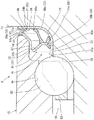
密封装置70は、図2及び図3に図示されるようにハブ軸1の軸部10及び内輪形成環状部材42によって構成される内輪の端部と、外輪部材45の端部の間を密封するものである。さらに、ハブ軸1の車輪側フランジ部21の側面と外輪部材45の間の開口部66を塞ぐように構成される。密封装置70は、概略、第1シール部材80と第2シール部材90とからなる。
2 and 3, the sealing
第1シール部材80は、図3に図示されるように第1芯金81と、第1リップ88と、第1防水部材89とを有している。第1芯金81は、金属製の板部材(例えばステンレス鋼板、めっき鋼板)を塑性加工、打抜加工などによって環状に形成されている。第1芯金81は、外周面が外輪部材45の一方の端部の内周面に圧入して嵌合される第1円筒部82と、第1円筒部82の一端から径方向外方に延出した第1環状部84と、第1円筒部82の端部から径方向内方に延出した第3環状部85によって断面が屈曲状に一体形成されている。第1芯金81の第1円筒部82の外周面は、外輪部材45の内周面に圧入して嵌合する嵌合面82bとして構成されている。
As shown in FIG. 3, the
第1リップ88は、外部からの水、埃、泥等の異物の侵入を防止するために構成される。第1リップ88は、第1芯金81の第3環状部85の先端からハブ軸1側に向かって延出される複数の弾性体である。第1リップ88は、例えば、ニトリルゴム、アクリルゴム等の合成ゴム、天然ゴム、軟質合成樹脂等を適宜選択することができる。本実施例においては合成ゴムが選択されており、第1芯金81の第3環状部85に加硫接着によって取り付けられている。第1リップ88は第2シール部材90の第2円筒部92及び第2環状部94に摺動することで外部からの水、埃、泥等の異物の侵入を防止する構成とされており、第2シール部材90の第2円筒部92及び第2環状部94に向かって3方向に突き出し状に形成されている。第1リップ88は、ラジアルリップ88a、補助リップ88b、サイドリップ88cの3構成である。第2シール部材90の第2円筒部92に構成される摺動面92aに対し径方向の弾性力を付与して摺動するのがラジアルリップ88a、補助リップ88bである。また、第2シール部材90の第2環状部94に構成される摺動面94aに対し軸方向の弾性力を付与して摺動するのがサイドリップ88cである。
The
第1防水部材89は、外周端縁84aと外輪部材45の車輪側フランジ部21側の端面との間に泥水が浸入するのを防ぐために設けられる。第1防水部材89は、第1芯金81の外周端縁84aから外輪部材45の車輪側フランジ部21側の端面まで回り込んで設けられる弾性体である。第1防水部材89は、弾性体で構成されており、例えば、ニトリルゴム、アクリルゴム等の合成ゴム、天然ゴム、軟質合成樹脂等を適宜選択することができる。本実施例においては合成ゴムが選択されており、第1芯金81の外周端縁84aに加硫接着によって取り付けられている。
The first
第2シール部材90は、図3に図示されるように第2芯金91と、第2リップ98と、第2防水部材99とを有している。第2芯金91は、金属製の板部材(例えばステンレス鋼板、めっき鋼板)を塑性加工、打抜加工などによって環状に形成されている。第2芯金91は、ハブ軸1の軸部10に圧入される第2円筒部92と、第2円筒部92の一端から径方向外方に延出する第2環状部94とによって断面L型状に一体形成されている。第2芯金91の外周側は、第1シール部材80に構成される第1リップ88と摺動する摺動面92a、94aを有する。
第2円筒部92の外周面は第1シール部材80に構成される第1リップ88のうち、ラジアルリップ88a、補助リップ88bと摺動する摺動面92aとして構成されており、裏面側の内周面はハブ軸1の隅部19の外周面に圧入により嵌合する嵌合面92bとして構成されている。第2環状部94のうち、第2円筒部92が配置される側の側面は、第1リップ88のうち、サイドリップ88cと摺動する摺動面94aとして構成されている。第2環状部94のうち、摺動面94aの裏面側の側面は、ハブ軸1の隅部19の位置において車輪側フランジ部21の側面と当接する当接面94bとして構成されている。
As shown in FIG. 3, the
The outer peripheral surface of the second
第2リップ98は、外部からの水、埃、泥等の異物の侵入を防止するために構成される。第2リップ98は、第2芯金91の外周端縁94cから第1芯金81側に向かって延出される弾性体である。第2リップ98は、例えば、ニトリルゴム、アクリルゴム等の合成ゴム、天然ゴム、軟質合成樹脂等を適宜選択することができる。本実施例においては合成ゴムが選択されており、第2シール部材90の第2環状部94の外周端縁94cに加硫接着によって取り付けられている。
第2リップ98は、第2環状部94の外周端縁94cから第1芯金81の第1環状部84に向かって傾斜して摺接する。換言すれば、第2リップ98は、第2環状部94の外周端縁94cから第2シール部材90の第2円筒部92が配置される方向に傾斜して延出して形成される。
これは、ハブ軸用軸受装置Aの組み立て状態において見ると第2リップ98が外輪部材45の端部における第1芯金81の第1環状部84に向かって傾斜して突き出し状に形成される関係となる。そのため、第2リップ98は、内輪が構成されるハブ軸1の回転に伴って第1環状部84に摺動して開口部66(内輪が構成されるハブ軸1の車輪側フランジ部21の側面と外輪部材45の間)を塞いで外部からの水、埃、泥等の異物の侵入を防止する。
また、第2リップ98の傾斜方向は、内輪が構成されるハブ軸1の回転に伴う遠心力作用によって第2リップ98と第1環状部84の当接が離脱可能な弾性力が作用する方向に構成される。
The
The
When viewed in the assembled state of the hub shaft bearing device A, the
The inclination direction of the
第2防水部材99は、第2シール部材90と車輪側フランジ部21の側面との間に泥水が浸入するのを防ぐために設けられる。
第2防水部材99は、第2芯金91の外周端縁94cからハブ軸1の車輪側フランジ部21の側面まで回り込んで設けられる弾性体である。第2防水部材99は、弾性体であり例えば、ニトリルゴム、アクリルゴム等の合成ゴム、天然ゴム、軟質合成樹脂等を適宜選択することができる。本実施例においては合成ゴムが選択されており、第2芯金91の外周端縁94cに加硫接着によって取り付けられている。なお、第2リップ98と第2防水部材99は、同質の合成ゴムで構成されているため一体に形成されている。
第1シール部材80と第2シール部材90は、第1円筒部82と第2円筒部92が互いに対向し、第1環状部84と第2環状部94が互いに対向する位置に配置される。
The second
The second
The
ハブ軸用軸受装置Aの組み立てを図2、3を用いて説明する。先ず、第2シール部材90は、ハブ軸1の隅部19の外周面上であって、かつ車輪側フランジ部21の側面に当接する位置まで圧入により嵌合される。次に、ハブ軸1の内輪軌道面18に保持器52で保持された玉50を嵌め込む。次に、外輪部材45の外輪軌道面46の形成側の端部の内周面に第1リップ88が取り付けられた第1シール部材80を圧入して組み付ける。次に、外輪部材45の外輪軌道面46をハブ軸1の内輪軌道面18と対向させる。次に、外輪部材45は、外輪軌道面46が玉50に当接する位置までハブ軸1の軸部10に嵌め込まれる。このとき、第1リップ88の先端部は、第2シール部材90の摺動面92a、94aに摺動する位置とされる。また、第2リップ98の先端部98aは、第1シール部材80の第1環状部84に摺動する位置とされる。次に、内輪形成環状部材42の内輪軌道面44に保持器53で保持された玉51を嵌め込む。次に、内輪形成環状部材42は、玉51が外輪軌道面47に当接する位置まで軸部10の小径部12の外周面に嵌め込まれる。軸端凹部16に治具を差し込んで径方向外方に拡開する。端軸部15の先端部は、径方向外方へかしめられて、かしめ部17が形成される。これにより小径部12の外周面に内輪形成環状部材42が固定される。なお、内輪軌道面18、44と外輪軌道面46、47との間に配設される各複数個の玉50、51には、軸部10の端軸部15をかしめて、かしめ部17を形成する際のかしめ力に基づいて所要とする軸方向の予圧が付与される。なお、内輪形成環状部材42の外周面には、速度センサ100に対応する被検出部105を周方向に有するパルサーリング106が必要に応じて圧入固定される。この場合、外輪部材45の端部内周面には、有蓋筒状のカバー部材101が圧入固定され、このカバー部材101の蓋板部102に速度センサ100が、その検出部をパルサーリング106の被検出部105に臨ませて取り付けられる。こうして、ハブ軸用軸受装置Aが構成される。
The assembly of the hub shaft bearing device A will be described with reference to FIGS. First, the
このように、実施形態1に係る車輪60のハブ軸用軸受装置A(車両用転がり軸受装置)によれば、第1シール部材80の第1リップ88は、第2シール部材90の第2芯金91の外周面に摺接して開口部66を密封し、第2シール部材90の第2リップ98は、第1シール部材80の第1芯金81に摺接して開口部66を密封する。即ち、第1シール部材80と第2シール部材90は、それぞれリップを有しており、互いの芯金に摺接することで開口部66を密封する。また、第1シール部材80は、第1防水部材89が圧入する外輪部材45まで回り込んで設けられている。また、第2シール部材90は、第2防水部材99が圧入するハブ軸1の車輪側フランジ部21の側面まで回り込んで設けられている。そのため、第1シール部材80と第2シール部材90は、それらの部材と圧入される部材との間の泥水の浸入を防止しさび等の腐食を防ぐことができる。これにより、ハブ軸用軸受装置Aのハブ軸1と外輪部材45との間の環状空間49のうち車輪側フランジ部21側の開口部66の泥水の浸入を抑制して耐泥水性向上を図ることができる。
As described above, according to the hub shaft bearing device A (vehicle rolling bearing device) for the
また、第2リップ98は、第2芯金91の外周端縁94cから第1芯金81に傾斜して摺接する構成である。そして、第2リップ98は、ハブ軸1の回転に伴う遠心力作用によって、第2リップ98と第1芯金81の当接が離れる傾斜方向に配設されている。これは、ハブ軸1の車輪側フランジ部21の側面と外輪部材45の間の開口部66を塞ぐような接触タイプのシール部材を追加することで耐泥水性向上を図ることが考えられる。しかし、第2リップ98が常に第1芯金81と接触した構成では、トルクが増加するおそれがあるという懸念が新たに生じる。
そこで、上記構成を採用することにより、ハブ軸1が低速回転時の状態では、ハブ軸1の車輪側フランジ部21の側面と外輪部材45の間の開口部66に泥水が浸入しやすいため第2リップ98の先端部98aが第1芯金81に摺動する。一方、ハブ軸1が高速回転時では、ハブ軸1の回転に伴う遠心力作用によって第2リップ98の先端部98aが第1芯金81から離れて非接触となる(仮想線で示す第2リップ98)。これにより、ハブ軸用軸受装置Aの高速回転時のトルクの増加を最小限に抑制できる。また、ハブ軸1の高速回転の状況下では、遠心力作用によって第2リップ98の先端部98aが第1芯金81から離間するに至り、それに伴い、この隙間から泥水が浸入またはこの隙間に滞留したとしても、この泥水にも遠心力が作用することにより外周側に吹き飛ばされるから、結果的に泥水が浸入しにくくなる(浸入しても迅速に排出される)。加えて少なくとも高速回転時には、第2リップ98が非接触状態を保持できるため、その磨耗も抑制することができる。また高速回転状況下では、第2リップ98と第1芯金81とは非接触であるため、摺動トルクを低減できることは言うまでもない。
そのため、第2リップ98の先端部98aが非接触状態でも耐泥水性は低下しない。これにより、ハブ軸用軸受装置Aのトルクの増加を最小限に抑制しつつ耐泥水性向上を図ることができる。
Further, the
Therefore, by adopting the above configuration, when the hub shaft 1 is rotating at a low speed, muddy water can easily enter the
Therefore, the muddy water resistance does not decrease even when the
また、第2シール部材90の第2リップ98と、第2防水部材99は、一体に形成することにより材料コスト、製造コストの抑制を図ることができる。
In addition, the
[実施形態2]
次に、本発明の実施形態2にかかる車輪60のハブ軸用軸受装置B(車両用転がり軸受装置)を図1、2、4にしたがって説明する。この実施形態2のその他の構成は実施形態1と同様に構成されるため、同一の符号を付して詳細な説明は省略することがある。
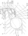
実施形態2におけるハブ軸用軸受装置Bの基本的な構成は、図1、2、4に示されるように、ハブ軸1(内輪)と、内輪形成環状部材42(内輪)と、外輪部材45(外輪)と、玉50、51(転動体)と保持器52、53と、密封装置270を主体として構成される。密封装置270は、概略、第1シール部材280と第2シール部材290とからなる。
[Embodiment 2]
Next, a hub shaft bearing device B (vehicle rolling bearing device) for a
As shown in FIGS. 1, 2, and 4, the basic configuration of the hub shaft bearing device B in the second embodiment is the hub shaft 1 (inner ring), the inner ring forming annular member 42 (inner ring), and the
第1シール部材280は、図4に図示されるように第1芯金281と、第1リップ88と、第1防水部材289とを有している。第1芯金281は、金属製の板部材(例えばステンレス鋼板、めっき鋼板)を塑性加工、打抜加工などによって環状に形成されている。第1芯金281は、その内周面が外輪部材45の一方の端部の外周面に圧入して嵌合される第1円筒部282と、第1円筒部282の一端から径方向内方に延出する第1環状部284によって断面が屈曲状に一体形成されている。第1円筒部282の内周面は、外輪部材45の外周面に圧入して嵌合する嵌合面282bとして構成されている。すなわち、第1芯金281の第1円筒部282は、外輪部材45の外周側に配設され、嵌合面282bが外輪部材45の外周面に圧入される。第1リップ88の構成は、実施形態1と実質的に同様である。
As shown in FIG. 4, the
第1防水部材289は、外輪部材45の車輪側フランジ部21側の端面との間に泥水が浸入するのを防ぐために設けられる。第1防水部材289は、第1芯金281の外周端縁282aに設けられる。第1防水部材289は、第1芯金281の外周端縁282aから外輪部材45の外周面まで回り込んで設けられる弾性体である。第1防水部材289は、弾性体で構成されており、例えば、ニトリルゴム、アクリルゴム等の合成ゴム、天然ゴム、軟質合成樹脂等を適宜選択することができる。本実施例においては合成ゴムが選択されており、第1芯金281の外周端縁282aに加硫接着によって取り付けられている。
The first
第2シール部材290は、図4に図示されるように第2芯金291と、第2リップ298と、第2防水部材299とを有している。第2芯金291は、金属製の板部材(例えばステンレス鋼板、めっき鋼板)を塑性加工、打抜加工などによって環状に形成されている。第2芯金291は、ハブ軸1の軸部10に圧入される第2円筒部292と、第2円筒部292の一端から径方向外方に延出する第2環状部294とによって断面L型状に一体形成されている。第2芯金291の外周側は、第1シール部材280に構成される第1リップ88と摺動する摺動面292a、294aを有する。なお、摺動面292a、294a、嵌合面292b、当接面294bの構成は、実施形態1と実質的に同様である。
As shown in FIG. 4, the
第2リップ298は、外部からの水、埃、泥等の異物の侵入を防止するために構成される。第2リップ298は、第2芯金291の外周端縁294cから第1芯金281側に向かって延出される弾性体である。第2リップ298は、例えば、ニトリルゴム、アクリルゴム等の合成ゴム、天然ゴム、軟質合成樹脂等を適宜選択することができる。本実施例においては合成ゴムが選択されており、第2シール部材290の第2環状部294の外周端縁294cに加硫接着によって取り付けられている。
The
第2防水部材299は、第2シール部材290と車輪側フランジ部21の側面との間に泥水が浸入するのを防ぐために設けられる。
第2防水部材299は、第2芯金91の外周端縁294cからハブ軸1の車輪側フランジ部21の側面まで回り込んで設けられる弾性体である。
第2防水部材299は、弾性体であり例えば、ニトリルゴム、アクリルゴム等の合成ゴム、天然ゴム、軟質合成樹脂等を適宜選択することができる。本実施例においては合成ゴムが選択されており、第2芯金91の外周端縁294cに加硫接着によって取り付けられている。
The second
The second
The second
ここで、第2防水部材299は、第2芯金91の外周端縁294cからハブ軸1の車輪側フランジ部21の側面まで回り込んで設けられると共に、径方向外方に延出され、外輪部材45の車輪側フランジ部21側の端面の径より大径に形成されている。
また、第2リップ298と第2防水部材299は、同質の合成ゴムで構成されて一体に形成されている。そのため、第2リップ298は、外輪部材45の外周面より径方向外方側から第1芯金281の第1円筒部282の外周面に向かって傾斜して摺接する。
これは、ハブ軸用軸受装置Bの組み立て状態において見ると第2リップ298が外輪部材45の外周面における第1芯金281の第1環状部284に向かって傾斜して突き出し状に形成される関係となる。そのため、第2リップ298は、内輪が構成されるハブ軸1の回転に伴って第1環状部284に摺動して開口部66(内輪が構成されるハブ軸1の車輪側フランジ部21の側面と外輪部材45の間)を塞いで外部からの水、埃、泥等の異物の侵入を防止する。
また、第2リップ298の傾斜方向は、内輪が構成されるハブ軸1の回転に伴う遠心力作用によって第2リップ298と第1環状部284の当接が離脱可能な弾性力が作用する方向に構成される(仮想線で示す第2リップ298)。
なお、ハブ軸用軸受装置Bの組み立ては、ハブ軸用軸受装置Aと実質的に同様である。
Here, the second
Further, the
When viewed in the assembled state of the hub shaft bearing device B, the
Further, the inclination direction of the
The assembly of the hub shaft bearing device B is substantially the same as the hub shaft bearing device A.
このように、実施形態2に係るハブ軸用軸受装置B(車両用転がり軸受装置)によれば、実施形態1と同様の作用効果を有することができる。また、第1芯金281の第1円筒部282は、外輪部材45の外周側に配設され、第1円筒部282の内周面が外輪部材45の外周面に圧入される構成である。これにより、第1防水部材289は、外輪部材45の外周面に配設されることとなる。これにより、第1防水部材289は、外輪部材45の外周面上の泥水が開口部66に流下する手前で阻止する構成となり、より一層、耐泥水性向上を図ることができる。
As described above, the hub shaft bearing device B (vehicle rolling bearing device) according to the second embodiment can have the same effects as those of the first embodiment. The first
以上、本発明の実施形態について説明したが、本発明の車輪のハブ軸用軸受装置は、本実施の形態に限定されず、その他各種の形態で実施することができるものである。
例えば、実施形態においては、従動輪について説明したが、本発明の車輪のハブ軸用軸受装置は、駆動輪についても適用可能な構成である。例えば、ドライブシャフトの一部を構成する等速自在継手の外側継手部材と、車輪を取付けるためのフランジ部をもったハブ軸と、複列転がり軸受とをユニット化した駆動輪であってもよい。
As mentioned above, although embodiment of this invention was described, the hub axle bearing apparatus of the wheel of this invention is not limited to this Embodiment, It can implement with other various forms.
For example, in the embodiment, the driven wheel has been described, but the hub axle bearing device for a wheel according to the present invention is also applicable to a drive wheel. For example, it may be a drive wheel in which an outer joint member of a constant velocity universal joint constituting a part of a drive shaft, a hub shaft having a flange portion for mounting a wheel, and a double row rolling bearing are unitized. .
また、第1リップ88、第1防水部材89,289、第2リップ98,298、第2防水部材99,299は弾性体であれば、種々の材料を適宜適用可能である。また、第2リップ98,298の先端部98a,298aは、相対的に根元部に比べて質量が大きい形状とされていてもよい。これは、内輪が構成されるハブ軸1の回転に伴う遠心力作用にともなう第2リップ98,298の弾性変形を促進するものとなる。また、第2リップ98,298と第2防水部材99,299は、別体に形成されていてもよい。
In addition, various materials can be appropriately applied as long as the
A ハブ軸用軸受装置(車両用転がり軸受装置)
1 ハブ軸(内輪)
10 軸部
11 大径部
12 小径部
15 端軸部
16 軸端凹部
17 かしめ部
18 内輪軌道面
19 隅部
21 車輪側フランジ部(フランジ部)
23 フランジ基部
24 ボルト孔
27 ハブボルト
30 嵌合軸部
31 ブレーキロータ用嵌合部
32 車輪用嵌合部
41 アンギュラ玉軸受
42 内輪形成環状部材(内輪)
43 内輪形成環状部材の内周面
44 内輪軌道面
45 外輪部材(外輪)
46 外輪軌道面
47 外輪軌道面
48 支持体側フランジ部
48a ボルト孔
49 環状空間
50 玉(転動体)
51 玉(転動体)
52 保持器
53 保持器
55 ブレーキロータ
54 ボルト
60 車輪
62 タイヤ
64 ホイール
66 開口部
70 密封装置
80 第1シール部材
81 第1芯金
82 第1円筒部
82b 嵌合面
84 第1環状部
84a 外周端縁
85 第3環状部
88 第1リップ
88a ラジアルリップ
88b 補助リップ
88c サイドリップ
89 第1防水部材
90 第2シール部材
91 第2芯金
92 第2円筒部
92a 摺動面
92b 嵌合面
94 第2環状部
94a 摺動面
94b 当接面
94c 外周端縁
98 第2リップ
98a 第2リップの先端部
99 第2防水部材
100 速度センサ
101 カバー部材
102 蓋板部
105 被検出部
106 パルサーリング
B ハブ軸用軸受装置(車両用転がり軸受装置)
270 密封装置
280 第1シール部材
281 第1芯金
282 第1円筒部
282a 外周端縁
282b 嵌合面
284 第1環状部
289 第1防水部材
290 第2シール部材
291 第2芯金
292 第2円筒部
292a 摺動面
292b 嵌合面
294 第2環状部
294a 摺動面
294b 当接面
294c 外周端縁
298 第2リップ
298a 第2リップの先端部
299 第2防水部材
A Hub shaft bearing device (rolling bearing device for vehicles)
1 Hub axle (inner ring)
DESCRIPTION OF
23
43 Inner ring forming annular member inner
46 outer
51 balls (rolling elements)
52 retainer 53
270
Claims (4)
前記密封装置は、第1シール部材と第2シール部材を備えており、
前記第1シール部材は、前記外輪に圧入される第1円筒部と該第1円筒部の一端から径方向内方又は径方向外方に延出する第1環状部とを有する第1芯金と、該第1芯金から前記内輪側に向かって延出する第1リップと、前記第1芯金の外周端縁から前記外輪まで回り込んで設けられる弾性体からなる第1防水部材とを有しており、
前記第2シール部材は、前記内輪に圧入される第2円筒部と該第2円筒部の一端から径方向外方に延出する第2環状部とを有する第2芯金と、該第2芯金の外周端縁から前記第1芯金側に向かって延出する第2リップと、前記第2芯金の外周端縁から前記内輪まで回り込んで設けられる弾性体からなる第2防水部材とを有し、
前記第1シール部材の第1リップは、前記第2芯金の外周面に摺接して前記開口部を密封し、
前記第2シール部材の第2リップは、前記第1芯金に摺接して前記開口部を密封することを特徴とする車両用転がり軸受装置。 An inner ring having a shaft portion of a hub shaft integrally formed with a flange portion to which a wheel can be attached, an outer ring concentric with the inner ring and disposed on the outer peripheral side of the inner ring, and between the inner ring and the outer ring A rolling bearing device for a vehicle including a rolling element that is rotatably disposed in the annular space, and a sealing device that seals the opening on the flange portion side of the annular space,
The sealing device includes a first seal member and a second seal member,
The first seal member has a first cylindrical portion having a first cylindrical portion press-fitted into the outer ring and a first annular portion extending radially inward or radially outward from one end of the first cylindrical portion. A first lip extending from the first core bar toward the inner ring side, and a first waterproof member made of an elastic body provided around the outer peripheral edge of the first core bar to the outer ring. Have
The second seal member includes a second cored bar having a second cylindrical part press-fitted into the inner ring and a second annular part extending radially outward from one end of the second cylindrical part; A second waterproof member comprising a second lip extending from the outer peripheral edge of the metal core toward the first metal core, and an elastic body provided around the outer peripheral edge of the second metal core to the inner ring And
The first lip of the first seal member is in sliding contact with the outer peripheral surface of the second core bar to seal the opening.
The rolling bearing device for a vehicle according to claim 2, wherein the second lip of the second seal member is in sliding contact with the first core bar to seal the opening.
前記第2リップは、前記第2芯金の外周端縁から第1芯金に傾斜して摺接する構成とされており、
前記第2リップは、前記内輪の回転に伴う遠心力作用によって、前記第2リップと第1芯金の摺接が離れる傾斜方向に配設されていることを特徴とする車両用転がり軸受装置。 The rolling bearing device for a vehicle according to claim 1,
The second lip is configured to be in sliding contact with the first cored bar inclined from the outer peripheral edge of the second cored bar,
The rolling bearing device for a vehicle according to claim 1, wherein the second lip is disposed in an inclined direction in which the sliding contact between the second lip and the first cored bar is separated by a centrifugal force action accompanying the rotation of the inner ring.
前記第2シール部材の第2リップと、第2防水部材は、一体に形成されていることを特徴とする車両用転がり軸受装置。 A rolling bearing device for a vehicle according to claim 1 or 2,
The rolling bearing device for a vehicle according to claim 2, wherein the second lip of the second seal member and the second waterproof member are integrally formed.
前記第1芯金の第1円筒部は、外輪の外周側に配設されており、
前記第1円筒部の内周面が前記外輪の外周面に圧入される構成であることを特徴とする車両用転がり軸受装置。
The rolling bearing device for a vehicle according to any one of claims 1 to 3,
The first cylindrical portion of the first cored bar is disposed on the outer peripheral side of the outer ring,
A rolling bearing device for a vehicle, wherein the inner peripheral surface of the first cylindrical portion is press-fitted into the outer peripheral surface of the outer ring.
Priority Applications (1)
| Application Number | Priority Date | Filing Date | Title |
|---|---|---|---|
| JP2012089142A JP2013217455A (en) | 2012-04-10 | 2012-04-10 | Rolling bearing device for vehicle |
Applications Claiming Priority (1)
| Application Number | Priority Date | Filing Date | Title |
|---|---|---|---|
| JP2012089142A JP2013217455A (en) | 2012-04-10 | 2012-04-10 | Rolling bearing device for vehicle |
Publications (1)
| Publication Number | Publication Date |
|---|---|
| JP2013217455A true JP2013217455A (en) | 2013-10-24 |
Family
ID=49589787
Family Applications (1)
| Application Number | Title | Priority Date | Filing Date |
|---|---|---|---|
| JP2012089142A Pending JP2013217455A (en) | 2012-04-10 | 2012-04-10 | Rolling bearing device for vehicle |
Country Status (1)
| Country | Link |
|---|---|
| JP (1) | JP2013217455A (en) |
Cited By (2)
| Publication number | Priority date | Publication date | Assignee | Title |
|---|---|---|---|---|
| JP2016080020A (en) * | 2014-10-14 | 2016-05-16 | Nok株式会社 | Sealing device |
| WO2022070592A1 (en) * | 2020-09-29 | 2022-04-07 | Nok株式会社 | Sealing device |
-
2012
- 2012-04-10 JP JP2012089142A patent/JP2013217455A/en active Pending
Cited By (2)
| Publication number | Priority date | Publication date | Assignee | Title |
|---|---|---|---|---|
| JP2016080020A (en) * | 2014-10-14 | 2016-05-16 | Nok株式会社 | Sealing device |
| WO2022070592A1 (en) * | 2020-09-29 | 2022-04-07 | Nok株式会社 | Sealing device |
Similar Documents
| Publication | Publication Date | Title |
|---|---|---|
| JP6603078B2 (en) | Wheel bearing device | |
| JP5836584B2 (en) | Wheel bearing device | |
| JP6275465B2 (en) | SEALING DEVICE AND WHEEL BEARING DEVICE HAVING THE SAME | |
| WO2011037183A1 (en) | Bearing device for a wheel | |
| WO2010013439A1 (en) | Wheel-bearing device | |
| JP2009197884A (en) | Wheel bearing device | |
| JP2010230150A (en) | Annular sealing device | |
| JP6336768B2 (en) | SEALING DEVICE AND WHEEL BEARING DEVICE HAVING THE SAME | |
| JP2010053893A (en) | Wheel-bearing device | |
| JP2012056411A (en) | Wheel bearing device | |
| JP2011007272A (en) | Wheel bearing device | |
| JP2008045673A (en) | Wheel bearing device | |
| JP6392531B2 (en) | Wheel bearing device | |
| JP2010032013A (en) | Bearing device for wheel | |
| JP2011088513A (en) | Bearing seal for wheels and bearing device for wheels equipped with the same | |
| JP2007192392A (en) | Bearing device for wheel | |
| JP2016003709A (en) | Wheel bearing device | |
| JP4679325B2 (en) | Wheel bearing device | |
| JP2013061048A (en) | Bearing unit for supporting wheel with seal | |
| JP5414964B2 (en) | Wheel bearing device | |
| JP2007303490A (en) | Bearing device for wheel | |
| JP2013217455A (en) | Rolling bearing device for vehicle | |
| JP5790109B2 (en) | Rolling bearing device | |
| JP2007100844A (en) | Bearing device for wheel | |
| JP2016109293A (en) | Rolling bearing unit for wheel support |