JP2013201614A - Speaker device and attachment method of the same - Google Patents
Speaker device and attachment method of the same Download PDFInfo
- Publication number
- JP2013201614A JP2013201614A JP2012068887A JP2012068887A JP2013201614A JP 2013201614 A JP2013201614 A JP 2013201614A JP 2012068887 A JP2012068887 A JP 2012068887A JP 2012068887 A JP2012068887 A JP 2012068887A JP 2013201614 A JP2013201614 A JP 2013201614A
- Authority
- JP
- Japan
- Prior art keywords
- speaker
- cabinet
- wall
- wall surface
- module
- Prior art date
- Legal status (The legal status is an assumption and is not a legal conclusion. Google has not performed a legal analysis and makes no representation as to the accuracy of the status listed.)
- Pending
Links
Images

Abstract
Description
本発明は、スピーカー装置及びスピーカー装置の取り付け方法に関する。 The present invention relates to a speaker device and a method for mounting the speaker device.
体育館や講堂などの広い空間で音声による案内放送を提供するPA(Public Address、放送設備)では、広い空間の後ろのほうまで音が届くよう、前方の壁面の高所に大型のスピーカー装置を取り付けることが多い。 In PA (Public Address, broadcasting equipment) that provides voice guidance broadcasting in large spaces such as gymnasiums and auditoriums, a large speaker device is installed at the height of the front wall so that the sound reaches the back of the wide space There are many cases.
スピーカー装置を壁面に固定するためには、ブラケット等の壁面への取り付け具をスピーカーキャビネットの背面等に取り付け、ブラケットを壁面に固定することでスピーカー装置を壁面に固定することが従来から行われている。また、背面に取付穴を設け、壁面から突出するねじに取付穴を掛けて固定するスピーカーシステムが知られている(たとえば、特許文献1参照)。 In order to fix the speaker device to the wall surface, it has been conventionally performed to fix the speaker device to the wall surface by attaching a bracket or the like to the wall surface of the speaker cabinet and fixing the bracket to the wall surface. Yes. In addition, a speaker system is known in which a mounting hole is provided on the rear surface and the mounting hole is fixed to a screw protruding from a wall surface (see, for example, Patent Document 1).
このような従来のスピーカー装置を設置する場合、スピーカー装置を持ち上げながら壁面に固定する作業を行う必要がある。しかし一般に、広い空間に音を伝えるスピーカー装置は、口径の大きなスピーカーユニットを用いることが多く、重量が極めて重い。そのため、スピーカー装置を持ち上げながら設置の作業を行うと、作業性が悪いという問題があった。 When such a conventional speaker device is installed, it is necessary to perform an operation of fixing the speaker device to the wall surface while lifting the speaker device. However, in general, a speaker device that transmits sound to a large space often uses a speaker unit having a large diameter, and is extremely heavy. Therefore, when the installation work is performed while lifting the speaker device, there is a problem that workability is poor.
そこで、本発明が解決しようとする課題は、スピーカー装置の設置の際の作業性を良好にする技術を提供することにある。 Therefore, the problem to be solved by the present invention is to provide a technique for improving the workability when installing the speaker device.
上記の課題を解決するために、本願発明は以下の装置、方法を提供するものである。
1)バッフル板(401)とバッフル板に取り付けられたスピーカーユニット(402)とを含むスピーカーモジュール(103)と、前面に開口部(102)を備え、開口部に複数のスピーカーモジュールを取り付けるキャビネット(101)と、スピーカーモジュールを外した状態で開口部をとおして固定部材を取り付け可能な位置に設けられた固定部材取付部(502)とを備えることを特徴とするスピーカー装置。
2)スピーカー装置は少なくとも2つ以上のスピーカーモジュール(103a、103b、103c、103d)を上下方向に等間隔で配列させることを特徴とする1)に記載のスピーカー装置。
3)スピーカーモジュールは左右方向に等間隔で配列された複数のスピーカーユニット(402a、402b)を備えることを特徴とする1)または2)に記載のスピーカー装置。
4)スピーカー装置はさらにスピーカーモジュールの音波の出力軸の傾きを調整する傾き調整手段を備えることを特徴とする1)から3)のいずれか一項に記載のスピーカー装置。
5)スピーカー装置を壁面に取り付ける取り付け方法であって、前面に設けられた開口部と、固定部材取り付け部とを有するキャビネットの前記開口部をとおして、固定部材を用いて前記固定部材取り付け部を壁面に固定することによりスピーカー装置を壁面に取り付ける壁面取り付けステップと、バッフル板(401)とバッフル板に取り付けられたスピーカーユニット(402)と含むスピーカーモジュールの複数個を順次スピーカー装置に取り付けるスピーカーモジュール取り付けステップとを含むことを特徴とするスピーカー装置の取付け方法。
In order to solve the above problems, the present invention provides the following apparatus and method.
1) A cabinet (103) including a baffle plate (401) and a speaker unit (402) attached to the baffle plate, and a cabinet having an opening (102) on the front surface and mounting a plurality of speaker modules in the opening ( 101) and a fixing member attaching portion (502) provided at a position where the fixing member can be attached through the opening with the speaker module removed.
2) The speaker device according to 1), wherein at least two speaker modules (103a, 103b, 103c, 103d) are arranged at equal intervals in the vertical direction.
3) The speaker device according to 1) or 2), wherein the speaker module includes a plurality of speaker units (402a, 402b) arranged at equal intervals in the left-right direction.
4) The speaker device according to any one of 1) to 3), wherein the speaker device further includes an inclination adjusting unit that adjusts an inclination of an output axis of a sound wave of the speaker module.
5) An attachment method for attaching a speaker device to a wall surface, wherein the fixing member attaching portion is attached using a fixing member through the opening of a cabinet having an opening provided on the front surface and a fixing member attaching portion. A speaker module attachment for attaching a plurality of speaker modules to a speaker device in sequence, including a wall surface attachment step for attaching the speaker device to the wall surface by fixing to the wall surface, and a baffle plate (401) and a speaker unit (402) attached to the baffle plate. A speaker device mounting method.
本発明によれば、スピーカー装置の設置の際の作業性を良好にすることができる。 According to the present invention, it is possible to improve workability when installing the speaker device.
以下、本発明のスピーカー装置の一実施形態について、添付図面を参照して説明する。
<構成>
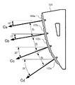
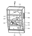
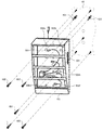
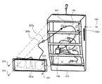
図1は本発明のスピーカー装置の一実施形態である壁掛け形スピーカー10を示す斜視図、図2は壁掛け形スピーカー10の側面図、図3はスピーカーモジュールを取りはすした状態の壁掛け形スピーカー10の斜視図である。本実施形態の壁掛け形スピーカー10は、主に広い空間においてアナウンスなどの拡声を目的としたPAで使用するものであり、壁面に取り付けて使用されるものとする。
Hereinafter, an embodiment of a speaker device of the present invention will be described with reference to the accompanying drawings.
<Configuration>
1 is a perspective view showing a wall-mounted
図1において、矢印Aの方向を正面とし、壁掛け形スピーカー10の正面に向いた側を前面、前面に対向する面を背面とする。また矢印Bの方向を上方向とする。
In FIG. 1, the direction of arrow A is the front, the side facing the front of the wall-mounted
キャビネット101の前面には図3に示すように4つの開口部102(102a、102b、102c、102d)が設けられている。図1および図2に示すように、4つの開口部102(102a、102b、102c、102d)にはそれぞれ4つのスピーカーモジュール103(103a、103b、103c、103d)が取り付けられている。またキャビネット101の背面には落下防止ワイヤー110が取り付けられている。
As shown in FIG. 3, four openings 102 (102a, 102b, 102c, 102d) are provided on the front surface of the
図1に示すように、スピーカーモジュール103は、前面からスピーカーモジュール取付ねじ104によってキャビネット101に取り付けられており、また側面から落下防止ねじ105によってさらにキャビネット101に固定されている。キャビネット101にはまた信号分配部106が設けられている。信号分配部106は、設置された状態ではスピーカーケーブル109でアンプ等に接続されている。信号分配部106は、スピーカーケーブル109を介して送られた音響信号から低域の音響信号と高域の音響信号との2つの異なる周波数帯域の成分を抽出する。信号分配部106にはまた、抽出した低域の音響信号と高域の音響信号とを4つのスピーカーモジュール103へ分配するため、先端にコネクタ107を備えた4本の分配ケーブル108が接続されている。
As shown in FIG. 1, the
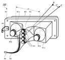
図4はスピーカーモジュール103を背面の右上方からみたときの斜視図である。図4において、バッフル板401aとホーン404とバッフル板401bとは一体に構成されており、後述のようにモジュールパネル407に対して約10度の傾斜を持たせた構造となっている。
FIG. 4 is a perspective view of the
バッフル板401aにはウーファ402aが取り付けられ、バッフル板401bには、ウーファ402aと横方向に間隔d1で離間する位置にウーファ402bが取り付けられている。またバッフル板401aとバッフル板401bとの間にはホーン404が設けられ、ホーン404には4つのツイータ403が取り付けられている。ウーファ402とツイータ403にはそれぞれケーブル405が接続されており、ケーブル405の先端にはコネクタ406が設けられている。ケーブル405のコネクタ406を、信号分配部106の分配ケーブル108のコネクタ107と接続することにより、信号分配部106で出力された低域の音響信号がウーファ402から出力され、高域の音響信号がツイータ403から出力される。
A
モジュールパネル407の前面にはウーファ402とツイータ403を保護するためのパンチングパネル408が取り付けられており、側面にはスピーカーモジュール103が落下しないようキャビネット101に固定するための落下防止金具409が取り付けられている。
A
パンチングパネル408は、外周部から突出させた足をモジュールパネル407に差し込んで折り曲げるほかに、モジュールパネル407とねじ止めしたり、接着剤を塗布するなどして、モジュールパネル407に強固に固定する。
The
前述のように、2つのウーファ402は左右に間隔d1で取り付けられており、トーンゾイレ方式のスピーカーを構成する。トーンゾイレ方式のスピーカーは、2つのスピーカーの間隔の2倍を波長とする音響信号に対して、高い指向性を示すことが知られている。したがって、ウーファ402から出力する低域の音響信号に対して左右の間隔d1を適切に設定することにより、低域の音響信号の左右方向の指向性を適切に設定することができる。 As described above, the two woofers 402 are attached to the left and right with a distance d1 to constitute a tone-Zoi-type speaker. It is known that a tone Zoire speaker exhibits high directivity with respect to an acoustic signal having a wavelength that is twice the interval between two speakers. Therefore, by appropriately setting the left-right distance d1 for the low-frequency acoustic signal output from the woofer 402, the left-right directionality of the low-frequency acoustic signal can be appropriately set.
また、高域の音響信号を出力するツイータ403は左右方向に広がるホーン404に取り付けられているので、ホーン404の形状を適切に設定することにより、高域の音響信号の左右方向の指向性を適切に設定することができる。
In addition, the
また図2に示すように、スピーカーモジュール103は、スピーカー装置10に取り付けられたとき上下方向にそれぞれ同じ間隔d2となり、スピーカーアレイを構成する。一般にスピーカーアレイは正面には互いの出力が重なり合い音量が大きくなるが、スピーカーが並んだ方向には互いの出力が干渉して指向角度が狭くなるという特徴を持つ。そのため上下の間隔d2を適切に設定することにより、壁掛け形スピーカー10の上下方向の指向性を適切に設定することができる。これにより、正面には大きな音量で出力するとともに、天井や床などに不要な音を出力することがない。
As shown in FIG. 2, when the
また、図4に示すように、スピーカーモジュール103が音を出力する方向である音軸を矢印C、モジュールパネル407の正面を矢印Aの方向とする。スピーカーモジュール103のバッフル板401及びホーン404は、音軸Cが正面Aに対し右に約10度傾くよう、モジュールパネル407に対して約10度傾けて構成されている。
Further, as shown in FIG. 4, the sound axis that is the direction in which the
なお、本実施形態の壁掛け形スピーカー10は壁面の向かって右側に取り付ける右側用の壁掛け形スピーカーであり、左側用の壁掛け形スピーカーと対となっている。右側用の壁掛け形スピーカーと左側用の壁掛け形スピーカーとは、取り付けるスピーカーモジュールの音軸の傾きの方向が異なっている。右側用の壁掛け形スピーカー10では図1に示すように右に傾けられ、左側用の壁掛け形スピーカーでは左に傾けられている。これにより、壁面の左右に取り付けられた壁掛け形スピーカーそれぞれやや内向きに音が出力され、広い空間に均一に音が伝わるようにするためである。
Note that the wall-mounted
スピーカーモジュール103の音軸はまた正面に対し上下方向にも傾斜を持つよう構成されている。図2に示すように、スピーカーモジュール103a、103b、103c、103dの音軸をCa、Cb、Cc、Cdとする。このとき、スピーカーモジュール103aの音軸Caとスピーカーモジュール103bの音軸Cbとはいずれも約10度下向きになるよう構成され、遠方に音を伝達する。これに対しスピーカーモジュール103cの音軸Ccは約20度下向きになるよう構成され、やや近傍に音を伝達する。さらにスピーカーモジュール103dの音軸Cdは約35度下向きになるよう構成され、最も近傍に音を伝達する。これにより、壁掛け形スピーカー10を傾けることなく、遠方から近傍まで広い範囲に音を伝達することができる。
The sound axis of the
また、スピーカーモジュール103の音軸の傾きを調整可能とすることも好適である。たとえば、スピーカーモジュール103をキャビネット101に取り付けるためのねじ穴を複数設けておき、取り付けに使用するねじ穴を適宜選択したり、スピーカーモジュール103とキャビネット101との間にスペーサーを挟み込むことにより、スピーカーモジュール103の傾きを調整することができる。スピーカーモジュール103の左右の傾きを調整することにより音軸の左右の傾きを調整し、音を伝達する空間の左右方向のさまざまな広さに対応して均一に音を伝達することができる。またスピーカーモジュール103の上下の傾きを調整することにより音軸の上下の傾きを調整し、音を伝達する空間の前後方向のさまざまな広さに対応したり、壁掛け形スピーカー10を壁面へ取り付けるときのさまざまな高さに対応して均一に音を伝達することができる。
It is also preferable that the inclination of the sound axis of the
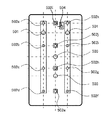
次に壁掛け形スピーカー10の背面図を図5に示す。キャビネット101の背面には、2つの位置決め用穴501と、10個の壁面取付用穴502(502a、502b、502c、502d、502e、502f、502g、502h、502i、502j)と、スピーカーケーブル109を通すための2つの通線用穴503と、落下防止ワイヤー110を取り付けるための落下防止ワイヤー取付穴504とが設けられている。壁面取付用穴502は、壁掛け形スピーカー10の前面から開口部102をとおして電動ドライバーなどで壁面への取り付けの作業ができる位置に設けられている。位置決め用穴501と壁面取付用穴502とは、背面に突出したリブの部分に孔設されており、設置されるとリブが壁面に密着する。通線用穴503には、不要な空間をふさぐための封止部材(図示しない)が設けられている。これにより、背面と壁面との間にスピーカーケーブル109を引き回すための空間を生じさせるとともに、キャビネット101の背面から空気が抜けて音響特性を損なうことを防いでいる。また落下防止ワイヤー取付穴504はキャビネット101から一段くぼませた部分に孔設されており、落下防止ワイヤー110を取り付けるネジの頭が突出することを防いでいる。
<設置の作業手順>
このような壁掛け形スピーカー10を壁面に取り付けるときは、作業者はまずスピーカーモジュール103のスピーカーモジュール取付ねじ104を取り外し、さらにコネクタ406をコネクタ107から外して、スピーカーモジュール103を取り外す。このようにして4つのスピーカーモジュール103をすべてキャビネット101から取り外す。そして落下防止ワイヤー110の一端をキャビネット101の背面の落下防止ワイヤー取付穴504に取り付ける。
Next, a rear view of the wall-mounted
<Installation procedure>
When attaching such a wall-mounted
次に作業者は、図6に示すように、左右を所定の間隔とした2本の位置決め用ねじ601を、壁面60の壁掛け形スピーカー10を取り付けたい位置に取り付ける。位置決め用ねじ601は、コンクリート壁に取り付ける場合などはアンカーボルトであってもよい。そしてキャビネット101を持ち上げて位置決め用穴501と位置決め用ねじ601との位置をあわせ、壁面に取り付けた位置決め用ねじ601に位置決め用穴501を差し込んで、キャビネット101を壁面に仮止めする。このとき、キャビネット101にはウーファ402やツイータ403などの重量の重いスピーカーユニットは搭載されていないので、キャビネット101を持ち上げてもさほど重くなく、作業性はよい。
Next, as shown in FIG. 6, the worker attaches two positioning
キャビネット101を壁面に仮止めしたら、次に作業者はキャビネット101の前面から、壁面取付用穴502に壁面取付用ねじ602を差し込んで壁面に取り付け、キャビネット101を壁面に固定する。壁面取付用穴502は本実施の形態では10箇所設けられているがすべてを使用する必要はなく、壁面の状態や使用状況などに合わせて使用する壁面取付用穴を適宜選択して固定すればよい。図6は壁面取付用穴502a、502d、502f、502h、502kの5箇所を用いて固定する例を示している。このときの作業は、スピーカーモジュール102を取り外したキャビネット101の開口部102から電動ドライバーなどを差し入れて行うことができ、作業性はよい。また、位置決め用の穴501や壁面取付用穴502はキャビネット101の内部にあるので、設置作業が完了するとスピーカーモジュール103に隠され、外観に露出せず好ましい。
Once the
また一般に体育館では球技を行う際にボールが壁掛け形スピーカーに当たることがあり、壁掛け形スピーカー自体を強固にするだけでなく、壁掛け形スピーカーを壁面に強固に固定することが求められる。本実施形態の壁掛け形スピーカー10は、面積の広いキャビネット101の背面を用いて壁面に取り付けることができる。取り付ける面積が広いので、取り付けが浮いたりぐらついたりすることがなく安定した状態で取り付けることができる。また、取り付ける面積が広いので、多くの壁面取付用ねじを用いて壁面に固定することができる。そのため、壁掛け形スピーカー10を壁面に強固に固定することができる。また、取り付ける面積が広いので、取付穴を多数設けていることができ、裏面に梁がとおっているところなど、壁の状態が取り付けに最も適した位置で固定することができる。
In general, in a gymnasium, when a ball game is performed, a ball may hit a wall-mounted speaker, and it is required not only to strengthen the wall-mounted speaker itself but also to firmly fix the wall-mounted speaker to the wall surface. The wall-hanging
また、前述のように、パンチングパネル408は、足の差し込みや、ねじ止めや、接着などによりモジュールパネル407に強固に固定されているので、ボールが当たっても破壊することがない。
Further, as described above, the punching
キャビネット101を壁面に固定したら、スピーカーモジュール103を再びキャビネット101に取り付ける。図7に示すように、まずスピーカーモジュール103aを持ち上げてキャビネット101の近傍に寄せ、キャビネット101の信号分配部106から出されている分配ケーブル108を開口部102aを通して引き出し、その先端のコネクタ107をケーブル405のコネクタ406と接続する。
After the
そしてスピーカーモジュール103aをキャビネット101の開口部102aの位置にはめ込み、スピーカーモジュール取付ねじ104を用いてキャビネット101に取り付ける。最後に、スピーカーモジュール取付ねじ104に不具合があってもスピーカーモジュール103aが落下しないよう、落下防止ねじ105を用いて落下防止金具409をキャビネット101の側面に固定する。このような作業をスピーカーモジュール103b、103c、103dについても順次行い、スピーカーモジュール103をすべて取り付ける。最後に、壁面取付用ねじ602に不具合があっても壁掛け形スピーカー10が落下しないように、キャビネット101の落下防止ワイヤー取付穴504に一端が固定された落下防止ワイヤー110の他端を壁面に固定して作業を終了する。
Then, the
スピーカーモジュール103を取り付けると、位置決め用の穴501、壁面取付用穴502、通線用穴503や、位置決め用ねじ601、壁面取付用ねじ602はすべてスピーカーモジュール103によって隠されることとなる。
When the
本実施形態の壁掛け形スピーカーは、大口径のウーファ、すなわち重量の極めて重いスピーカーユニットを用いず、中程度の口径のウーファ、すなわち重量のさほど重くないスピーカーユニットを複数個用いている。さらにそれらのウーファを複数のスピーカーモジュールに分けて取り付けているので、ひとつのスピーカーモジュールの重量はさほど重くはない。したがって、複数のスピーカーモジュールを順次取り付けていけば、重量の重いものを持ち上げながら作業を行う必要がなく、設置の際の作業性が良好である。 The wall-mounted speaker of this embodiment does not use a large-diameter woofer, that is, an extremely heavy speaker unit, and uses a medium-diameter woofer, that is, a speaker unit that is not so heavy. Furthermore, since those woofers are divided into a plurality of speaker modules and attached, the weight of one speaker module is not so heavy. Therefore, if a plurality of speaker modules are sequentially attached, there is no need to work while lifting a heavy weight, and the workability during installation is good.
10 壁掛け形スピーカー
101 キャビネット
102 開口部
103 スピーカーモジュール
104 スピーカーモジュール取付ねじ
105 落下防止ねじ
106 信号分配部
107 コネクタ
108 分配ケーブル
109 スピーカーケーブル
110 落下防止ワイヤー
DESCRIPTION OF
Claims (5)
前面に開口部を備え、前記開口部に複数の前記スピーカーモジュールを取り付けるキャビネットと、
前記スピーカーモジュールを外した状態で前記開口部をとおして固定部材を取り付け可能な位置に設けられた固定部材取付部と
を備えることを特徴とするスピーカー装置。 A speaker module including a baffle plate and a speaker unit attached to the baffle plate;
A cabinet having an opening on the front surface, and a plurality of the speaker modules attached to the opening;
A speaker device comprising: a fixing member attaching portion provided at a position where the fixing member can be attached through the opening with the speaker module removed.
前記少なくとも2つ以上のスピーカーモジュールを上下方向に等間隔で配列させる
ことを特徴とする請求項1に記載のスピーカー装置。 The speaker device according to claim 1, wherein the speaker device has the at least two or more speaker modules arranged in the vertical direction at equal intervals.
左右方向に等間隔で配列された複数のスピーカーユニット
を備えることを特徴とする請求項1または2に記載のスピーカー装置。 The speaker device according to claim 1, wherein the speaker module includes a plurality of speaker units arranged at equal intervals in the left-right direction.
前記スピーカーモジュールの音波の出力軸の傾きを調整する傾き調整手段
を備えることを特徴とする請求項1から3のいずれか一項に記載のスピーカー装置。 4. The speaker device according to claim 1, further comprising an inclination adjusting unit that adjusts an inclination of an output axis of a sound wave of the speaker module. 5.
前面に設けた開口部と、固定部材取り付け部とを有するキャビネットの前記開口部をとおして、固定部材を用いて前記固定部材取り付け部を壁面に固定することにより前記キャビネットを壁面に取り付ける壁面取り付けステップと、
バッフル板と前記バッフル板に取り付けられたスピーカーユニットとを含むスピーカーモジュールの複数個を、前記開口部をふさぐようにして順次前記キャビネットに取り付けるスピーカーモジュール取り付けステップと
を含むことを特徴とするスピーカー装置の取付け方法。 An attachment method for attaching a speaker device to a wall,
A wall surface attaching step for attaching the cabinet to the wall surface by fixing the fixing member attachment portion to the wall surface using the fixing member through the opening portion of the cabinet having the opening portion provided on the front surface and the fixing member attaching portion. When,
A speaker module mounting step of sequentially mounting a plurality of speaker modules including a baffle plate and a speaker unit mounted on the baffle plate to the cabinet so as to close the opening. How to install.
Priority Applications (1)
| Application Number | Priority Date | Filing Date | Title |
|---|---|---|---|
| JP2012068887A JP2013201614A (en) | 2012-03-26 | 2012-03-26 | Speaker device and attachment method of the same |
Applications Claiming Priority (1)
| Application Number | Priority Date | Filing Date | Title |
|---|---|---|---|
| JP2012068887A JP2013201614A (en) | 2012-03-26 | 2012-03-26 | Speaker device and attachment method of the same |
Publications (1)
| Publication Number | Publication Date |
|---|---|
| JP2013201614A true JP2013201614A (en) | 2013-10-03 |
Family
ID=49521491
Family Applications (1)
| Application Number | Title | Priority Date | Filing Date |
|---|---|---|---|
| JP2012068887A Pending JP2013201614A (en) | 2012-03-26 | 2012-03-26 | Speaker device and attachment method of the same |
Country Status (1)
| Country | Link |
|---|---|
| JP (1) | JP2013201614A (en) |
Cited By (1)
| Publication number | Priority date | Publication date | Assignee | Title |
|---|---|---|---|---|
| WO2018216195A1 (en) * | 2017-05-26 | 2018-11-29 | ヤマハ株式会社 | Loudspeaker device |
Citations (7)
| Publication number | Priority date | Publication date | Assignee | Title |
|---|---|---|---|---|
| JPS4812499Y1 (en) * | 1969-07-10 | 1973-04-05 | ||
| JPS4816974Y1 (en) * | 1969-07-04 | 1973-05-15 | ||
| JPS56172079U (en) * | 1980-05-21 | 1981-12-18 | ||
| JPS58182991A (en) * | 1982-04-21 | 1983-10-26 | Matsushita Electric Ind Co Ltd | Speaker system |
| JPH02154599A (en) * | 1988-12-06 | 1990-06-13 | Matsushita Electric Ind Co Ltd | Speaker fitting plate |
| JPH0356285U (en) * | 1989-10-05 | 1991-05-30 | ||
| JP2010068312A (en) * | 2008-09-11 | 2010-03-25 | Toa Corp | Loudspeaker fitting device |
-
2012
- 2012-03-26 JP JP2012068887A patent/JP2013201614A/en active Pending
Patent Citations (7)
| Publication number | Priority date | Publication date | Assignee | Title |
|---|---|---|---|---|
| JPS4816974Y1 (en) * | 1969-07-04 | 1973-05-15 | ||
| JPS4812499Y1 (en) * | 1969-07-10 | 1973-04-05 | ||
| JPS56172079U (en) * | 1980-05-21 | 1981-12-18 | ||
| JPS58182991A (en) * | 1982-04-21 | 1983-10-26 | Matsushita Electric Ind Co Ltd | Speaker system |
| JPH02154599A (en) * | 1988-12-06 | 1990-06-13 | Matsushita Electric Ind Co Ltd | Speaker fitting plate |
| JPH0356285U (en) * | 1989-10-05 | 1991-05-30 | ||
| JP2010068312A (en) * | 2008-09-11 | 2010-03-25 | Toa Corp | Loudspeaker fitting device |
Cited By (2)
| Publication number | Priority date | Publication date | Assignee | Title |
|---|---|---|---|---|
| WO2018216195A1 (en) * | 2017-05-26 | 2018-11-29 | ヤマハ株式会社 | Loudspeaker device |
| US10924831B2 (en) | 2017-05-26 | 2021-02-16 | Yamaha Corporation | Speaker device |
Similar Documents
| Publication | Publication Date | Title |
|---|---|---|
| US8631897B2 (en) | Ceiling loudspeaker system | |
| US8286749B2 (en) | Ceiling loudspeaker system | |
| EP3133832A1 (en) | Thin high performance constant directivity waveguide and speaker | |
| US8672087B2 (en) | Ceiling loudspeaker support system | |
| KR102279599B1 (en) | Speaker apparatus | |
| US8276706B2 (en) | Method and apparatus for a loudspeaker assembly | |
| US7840018B2 (en) | In-wall sub-woofer system with high-volume displacement | |
| WO2012174159A1 (en) | Ceiling loudspeaker system | |
| JP2002199484A (en) | Line electroacoustical transducing | |
| KR100618296B1 (en) | Housing having a loudspeaker system | |
| US6766027B2 (en) | Elliptical flushmount speaker | |
| US9113244B2 (en) | Loudspeaker for eliminating a frequency response dip | |
| US8630438B2 (en) | Speaker isolation system | |
| US20030048918A1 (en) | Installing a high fidelity sound, voice paging, or music system by mounting an electrical to acoustic transducer inside a wall mounted gang box | |
| JP2013201614A (en) | Speaker device and attachment method of the same | |
| EP1061769A2 (en) | Loudspeaker | |
| KR20080068289A (en) | The dual speaker | |
| CN110271495A (en) | Chamber mount and vehicle for vehicle speakers unit | |
| US10616678B2 (en) | Tunable bass reflex ceiling mounted speaker system | |
| KR100255239B1 (en) | Ac-3 or thx compatible type surround speaker | |
| WO2007127822A2 (en) | Reconfigurable audio-video surround sound receiver (avr) and method | |
| KR200485547Y1 (en) | Speaker fixing apparatus capable of controlling directivity angle by frequency band | |
| WO2015167273A1 (en) | Speaker apparatus | |
| US20020186859A1 (en) | Framework for home theater systems | |
| SERIES | P10j |
Legal Events
| Date | Code | Title | Description |
|---|---|---|---|
| A621 | Written request for application examination |
Free format text: JAPANESE INTERMEDIATE CODE: A621 Effective date: 20140829 |
|
| A977 | Report on retrieval |
Free format text: JAPANESE INTERMEDIATE CODE: A971007 Effective date: 20150514 |
|
| A131 | Notification of reasons for refusal |
Free format text: JAPANESE INTERMEDIATE CODE: A131 Effective date: 20150526 |
|
| A02 | Decision of refusal |
Free format text: JAPANESE INTERMEDIATE CODE: A02 Effective date: 20151215 |