JP2013201564A - Acoustic processing device - Google Patents
Acoustic processing device Download PDFInfo
- Publication number
- JP2013201564A JP2013201564A JP2012068131A JP2012068131A JP2013201564A JP 2013201564 A JP2013201564 A JP 2013201564A JP 2012068131 A JP2012068131 A JP 2012068131A JP 2012068131 A JP2012068131 A JP 2012068131A JP 2013201564 A JP2013201564 A JP 2013201564A
- Authority
- JP
- Japan
- Prior art keywords
- sound
- acoustic signal
- sound image
- operation target
- image
- Prior art date
- Legal status (The legal status is an assumption and is not a legal conclusion. Google has not performed a legal analysis and makes no representation as to the accuracy of the status listed.)
- Granted
Links
Images


Abstract
Description
本発明は、複数チャネルの音響信号で形成される音場を制御する技術に関する。 The present invention relates to a technique for controlling a sound field formed by acoustic signals of a plurality of channels.
複数チャネルの音響信号の再生で形成される音場を利用者からの指示に応じて可変に制御する各種の技術が従来から提案されている。例えば非特許文献1には、図8に示すように、再生音の受聴者の位置に相当する基準点90を中心とした円形領域92を、複数の放音装置94が形成する音場を表現するGUI(Graphical User Interface)として表示装置に表示する技術が開示されている。利用者は、円形領域92に対する操作で再生音の定位方向96を任意に指定することが可能である。
Various techniques have been proposed in the past for variably controlling a sound field formed by reproducing sound signals of a plurality of channels in accordance with instructions from a user. For example, in Non-Patent Document 1, as shown in FIG. 8, a sound field formed by a plurality of
しかし、再生音全体の定位位置を利用者が指定する非特許文献1の技術では、音響信号のうち特定の帯域内の成分の定位方向を選択的に制御することや、音響信号のうち特定の方向に定位する成分の定位方向を選択的に制御することが想定されていない。したがって、例えば、相異なる位置に設置された複数の音源が並列に発音した音響の混合音のうち、所望の方向に位置する所望の音域の音源からの音響(例えば特定の楽器の演奏音)についてのみ選択的に定位方向を変更するといった精緻な調整はできない。以上の事情を考慮して、本発明は、音響信号の各周波数成分の定位方向を精緻かつ容易に調整することを目的とする。 However, in the technique of Non-Patent Document 1 in which the user specifies the localization position of the entire reproduced sound, the localization direction of the component within a specific band of the acoustic signal is selectively controlled, or the specific position of the acoustic signal is specified. It is not assumed that the localization direction of the component localized in the direction is selectively controlled. Therefore, for example, about the sound (for example, the performance sound of a specific musical instrument) from a sound source in a desired range located in a desired direction among the mixed sound of sounds generated in parallel by a plurality of sound sources installed at different positions. It is not possible to make precise adjustments such as selectively changing the orientation direction. In view of the above circumstances, an object of the present invention is to precisely and easily adjust the localization direction of each frequency component of an acoustic signal.
以上の課題を解決するために本発明が採用する手段を説明する。なお、本発明の理解を容易にするために、以下の説明では、本発明の要素と後述の実施形態の要素との対応を括弧書で付記するが、本発明の範囲を実施形態の例示に限定する趣旨ではない。 Means employed by the present invention to solve the above problems will be described. In order to facilitate the understanding of the present invention, in the following description, the correspondence between the elements of the present invention and the elements of the embodiments described later will be indicated in parentheses, but the scope of the present invention will be exemplified in the embodiments. It is not intended to be limited.
本発明の音響処理装置は、第1音響信号(例えば音響信号X)から複数チャネルの第2音響信号(例えば音響信号Y)を生成する装置であって、基準点を中心とした半径方向が周波数に対応するとともに円周方向が定位方向に対応する音像平面内での第1音響信号の各周波数成分の音像分布を表現する音像分布画像(例えば音像分布画像50)を表示装置に表示させる手段であって、音像平面のうち半径方向に設定された周波数範囲(例えば周波数範囲AF)と円周方向に設定された定位範囲(例えば定位範囲AP)とに対応する操作対象領域(例えば操作対象領域B)内の音像分布を利用者からの指示に応じて円周方向に移動させる表示制御手段(例えば表示制御部36)と、第2音響信号の各周波数成分の音像分布が、操作対象領域の移動後の音像分布画像が表現する音像分布に対応するように、第1音響信号から第2音響信号を生成する信号処理手段(例えば信号処理部42)とを具備する。 The acoustic processing device of the present invention is a device that generates a plurality of channels of second acoustic signals (for example, acoustic signal Y) from a first acoustic signal (for example, acoustic signal X), and a radial direction centered on a reference point is a frequency. And a sound image distribution image (for example, a sound image distribution image 50) representing the sound image distribution of each frequency component of the first acoustic signal in the sound image plane whose circumferential direction corresponds to the localization direction. An operation target area (for example, operation target area B) corresponding to a frequency range (for example, frequency range AF) set in the radial direction and a localization range (for example, localization range AP) set in the circumferential direction in the sound image plane. ) In the circumferential direction in accordance with an instruction from the user, and the sound image distribution of each frequency component of the second acoustic signal is moved in the operation target area. Of such sound image distribution image corresponding to the sound distribution of representing comprises a signal processing means for generating a second audio signal from the first acoustic signal (e.g. the signal processor 42).
以上の構成では、音像平面のうち特定の周波数範囲と特定の定位範囲とに対応する操作対象領域内の音像分布が利用者からの指示に応じて移動するから、非特許文献1の技術と比較して、各周波数成分の定位方向を精緻に調整することが可能である。また、基準点を中心とした円周方向に操作対象領域内の音像分布が移動するから、音像平面内の音像分布を視覚的および直観的に確認しながら利用者が各周波数成分の定位方向を容易に調整できるという利点もある。なお、操作対象領域(音像分布)の「移動」は、操作前の操作対象領域を維持しない狭義の「移動」と、操作前の操作対象領域を維持する「複製」との双方を含意する。 In the above configuration, since the sound image distribution in the operation target region corresponding to the specific frequency range and the specific localization range in the sound image plane moves according to the instruction from the user, it is compared with the technique of Non-Patent Document 1. Thus, the localization direction of each frequency component can be precisely adjusted. Also, since the sound image distribution in the operation target area moves in the circumferential direction around the reference point, the user can determine the localization direction of each frequency component while visually and intuitively checking the sound image distribution in the sound image plane. There is also an advantage that it can be easily adjusted. The “movement” of the operation target area (sound image distribution) implies both “move” in a narrow sense that does not maintain the operation target area before the operation and “duplication” that maintains the operation target area before the operation.
本発明の好適な態様において、表示制御手段は、音像平面のうち第1音響信号の各周波数成分が分布する初期分布領域(例えば初期分布領域A0)の内側に画定された操作対象領域を、利用者からの指示に応じて初期分布領域の外側に移動する。以上の態様では、操作対象領域内の音像分布が初期分布領域の内側から外側に移動するから、再生音の音像が分布する範囲を拡張することが可能である。 In a preferred aspect of the present invention, the display control means uses an operation target area defined inside an initial distribution area (for example, the initial distribution area A0) in which each frequency component of the first acoustic signal is distributed in the sound image plane. In response to an instruction from the person, it moves outside the initial distribution area. In the above aspect, since the sound image distribution in the operation target area moves from the inside to the outside of the initial distribution area, it is possible to extend the range in which the sound image of the reproduced sound is distributed.
本発明の好適な態様において、表示制御手段は、周波数範囲と定位範囲とを利用者からの指示に応じて可変に設定する。以上の態様では、操作対象領域を規定する周波数範囲と定位範囲とが利用者からの指示に応じて可変に設定されるから、利用者の所望の方向に定位する所望の帯域内の周波数成分(例えば特定の方向に配置された楽器の演奏音)の定位方向を選択的に変更するといった多様かつ精緻な調整が実現される。 In a preferred aspect of the present invention, the display control means variably sets the frequency range and the localization range in accordance with an instruction from the user. In the above aspect, since the frequency range and the localization range that define the operation target region are variably set in accordance with an instruction from the user, the frequency components (in a desired band localized in the user's desired direction) ( For example, various and precise adjustments such as selectively changing the localization direction of the performance sound of a musical instrument arranged in a specific direction are realized.
本発明の好適な態様において、表示制御手段は、操作対象領域内の各周波数成分の強度値(例えば強度値E)を、当該操作対象領域に対応した位置に配置するとともに利用者からの指示に応じて変更し、信号処理手段は、操作対象領域内の各周波数成分の強度を、当該操作対象領域に対応する強度値に応じて調整する。以上の態様では、操作対象領域に対応する強度値が利用者からの指示に応じて変更されるとともに信号処理手段による第1音響信号の調整に適用される。したがって、所望の周波数範囲および所望の定位範囲内の各周波数成分の強度を利用者が視覚的および直観的に調整できるという利点がある。なお、操作対象領域を他の位置に複製する場合、複製前の操作対象領域および複製後の操作対象領域の双方について強度値を配置する構成が好適である。 In a preferred aspect of the present invention, the display control means arranges the intensity value (for example, the intensity value E) of each frequency component in the operation target area at a position corresponding to the operation target area, and in response to an instruction from the user. The signal processing unit adjusts the intensity of each frequency component in the operation target area according to the intensity value corresponding to the operation target area. In the above aspect, the intensity value corresponding to the operation target region is changed according to an instruction from the user, and is applied to the adjustment of the first acoustic signal by the signal processing means. Therefore, there is an advantage that the user can visually and intuitively adjust the intensity of each frequency component within the desired frequency range and the desired localization range. In the case where the operation target area is duplicated at another position, a configuration in which intensity values are arranged for both the operation target area before duplication and the operation target area after duplication is preferable.
本発明の好適な態様において、表示制御手段は、第2音響信号の各チャネルの放音装置を表象する放音地点画像(例えば放音地点画像60)を、基準点を中心とした円周方向の各位置に配置するとともに、円周方向における放音地点画像の位置を利用者からの指示に応じて可変に設定し、信号処理手段は、放音地点画像の各位置に配置された放音装置が第2音響信号を再生した場合の各周波数成分の音像分布が、音像分布画像が表現する音像分布に対応するように、第1音響信号から第2音響信号を生成する。以上の態様では、放音地点画像の位置が利用者からの指示に応じて可変に設定されて再生音の音像分布に反映される。したがって、放音装置の実際の配置に対応するように放音地点画像の位置を調整することで、音像分布画像で表現される音像分布を現実の音響空間にて忠実に再現することが可能である。 In a preferred aspect of the present invention, the display control means uses a sound emission point image (for example, the sound emission point image 60) representing the sound emission device of each channel of the second acoustic signal in the circumferential direction around the reference point. And the position of the sound emitting point image in the circumferential direction is variably set according to an instruction from the user, and the signal processing means is configured to output the sound emitting sound arranged at each position of the sound emitting point image. The second sound signal is generated from the first sound signal so that the sound image distribution of each frequency component when the apparatus reproduces the second sound signal corresponds to the sound image distribution represented by the sound image distribution image. In the above aspect, the position of the sound emission point image is variably set according to an instruction from the user and reflected in the sound image distribution of the reproduced sound. Therefore, by adjusting the position of the sound emission point image so as to correspond to the actual arrangement of the sound emission device, it is possible to faithfully reproduce the sound image distribution represented by the sound image distribution image in the actual acoustic space. is there.
以上の各態様に係る音響処理装置は、音響信号の処理に専用されるDSP(Digital Signal Processor)などのハードウェア(電子回路)によって実現されるほか、CPU(Central Processing Unit)等の汎用の演算処理装置とプログラムとの協働によっても実現される。本発明のプログラムは、第1音響信号から複数チャネルの第2音響信号を生成するために、基準点を中心とした半径方向が周波数に対応するとともに円周方向が定位方向に対応する音像平面内での第1音響信号の各周波数成分の音像分布を表現する音像分布画像を表示装置に表示させる処理であって、音像平面のうち半径方向に設定された周波数範囲と円周方向に設定された定位範囲とに対応する操作対象領域内の音像分布を利用者からの指示に応じて円周方向に移動させる表示制御処理と、第2音響信号の各周波数成分の音像分布が、操作対象領域の移動後の音像分布画像が表現する音像分布に対応するように、第1音響信号から第2音響信号を生成する信号処理とをコンピュータに実行させる。以上のプログラムによれば、本発明の音響処理装置と同様の作用および効果が奏される。本発明のプログラムは、コンピュータが読取可能な記録媒体に格納された形態で提供されてコンピュータにインストールされるほか、通信網を介した配信の形態で提供されてコンピュータにインストールされる。 The sound processing apparatus according to each of the above aspects is realized by hardware (electronic circuit) such as a DSP (Digital Signal Processor) dedicated to processing of an acoustic signal, or a general-purpose operation such as a CPU (Central Processing Unit). This is also realized by cooperation between the processing device and the program. In order to generate a second acoustic signal of a plurality of channels from the first acoustic signal, the program of the present invention is in the sound image plane in which the radial direction around the reference point corresponds to the frequency and the circumferential direction corresponds to the localization direction. Display the sound image distribution image representing the sound image distribution of each frequency component of the first acoustic signal in the display device, the frequency range set in the radial direction and the circumferential direction set in the sound image plane Display control processing for moving the sound image distribution in the operation target area corresponding to the localization range in the circumferential direction according to an instruction from the user, and the sound image distribution of each frequency component of the second acoustic signal are A computer is caused to execute signal processing for generating a second acoustic signal from the first acoustic signal so as to correspond to the sound image distribution represented by the moved sound image distribution image. According to the above program, the same operation and effect as the sound processing apparatus of the present invention are exhibited. The program of the present invention is provided in a form stored in a computer-readable recording medium and installed in the computer, or is provided in a form distributed via a communication network and installed in the computer.
<第1実施形態>
図1は、本発明の第1実施形態に係る音響処理装置100のブロック図である。図1に示すように、音響処理装置100には信号供給装置12と5個の放音装置14(14C,14L,14R,14LS,14RS)とが接続される。信号供給装置12は、複数の音源が発音した複数の音響(歌唱音や楽器音)の混合音の波形を示す音響信号Xを音響処理装置100に供給する。音響信号Xは、各音源に対応する音像が相異なる位置に定位するように収音または加工(例えば左右チャネル間の強度比や遅延量を変更する処理)された左チャネルの音響信号XLと右チャネルの音響信号XRとで構成されるステレオ信号である。周囲の音響を収音して音響信号X(XL,XR)を生成する収音機器や、可搬型または内蔵型の記録媒体から音響信号Xを取得する再生装置や、通信網から音響信号Xを受信する通信装置が信号供給装置12として採用され得る。なお、音響処理装置100と信号供給装置12とを一体に構成することも可能である。
<First Embodiment>
FIG. 1 is a block diagram of a
各放音装置14は、受聴者Hを包囲する位置に配置される。放音装置14Cは受聴者Hの前方に配置され、放音装置14Lは受聴者Hの左前方に配置され、放音装置14Rは受聴者Hの右前方に配置され、放音装置14LSは受聴者Hの左後方に配置され、放音装置14RSは受聴者Hの右後方に配置される。すなわち、第1実施形態は、音響処理装置100を利用した5チャネルのサラウンドシステムである。なお、低音用の放音装置(ウーハ)を追加することで5.1チャネルのサラウンドシステムを構成することも可能である。
Each sound emitting device 14 is arranged at a position surrounding the listener H. The sound emitting device 14C is arranged in front of the listener H, the
音響処理装置100は、左右2チャネルの音響信号Xからサラウンド形式の5チャネルの音響信号Y(YC,YL,YR,YLS,YRS)を生成する信号処理装置である。各放音装置14は、音響処理装置100が生成した音響信号Yに応じた音波を再生する。具体的には、放音装置14Cは音響信号YCを再生し、放音装置14Lは音響信号YLを再生し、放音装置14Rは音響信号YRを再生し、放音装置14LSは音響信号YLSを再生し、放音装置14RSは音響信号YRSを再生する。音響信号XLは放音装置14Lからの再生を想定して生成され、音響信号XRは放音装置14Rからの再生を想定して生成される。
The
図1に示すように、音響処理装置100は、演算処理装置22と記憶装置24と表示装置26と入力装置28とを具備するコンピュータシステムで実現される。表示装置26(例えば液晶表示パネル)は、演算処理装置22からの指示に応じて各種の画像を表示する。入力装置28は、音響処理装置100に対する利用者からの指示を受付ける機器であり、例えば利用者が操作する複数の操作子を含んで構成される。なお、表示装置26と一体に構成されたタッチパネルを入力装置28として利用することも可能である。
As shown in FIG. 1, the
記憶装置24は、演算処理装置22が実行するプログラムや演算処理装置22が使用する各種の情報を記憶する。半導体記録媒体や磁気記録媒体等の公知の記録媒体または複数種の記録媒体の組合せが記憶装置24として任意に採用される。なお、各音響信号Xを記憶装置24に格納した構成(したがって信号供給装置12は省略される)も採用され得る。
The
演算処理装置22は、記憶装置24に格納されたプログラムを実行することで、左右2チャネルの音響信号X(XL,XR)から5チャネルの音響信号Y(YC,YL,YR,YLS,YRS)を生成(アップミックス)するための複数の機能(周波数分析部32,定位解析部34,表示制御部36,信号処理部42,波形合成部44)を実現する。なお、演算処理装置22の各機能を複数の装置に分散した構成や、演算処理装置22の一部の機能を専用の電子回路(DSP)が実現する構成も採用され得る。
The
周波数分析部32は、音響信号XLおよび音響信号XRの各々について、相異なる周波数F[k]に対応する複数の周波数成分(周波数スペクトル)を時間軸上の単位期間毎に順次に算定する。記号kは、周波数軸上に設定された複数の周波数(周波数帯域)のうち任意の1個の周波数を指示する変数である。音響信号XLおよび音響信号XRの各周波数成分の算定には、例えば短時間フーリエ変換等の公知の周波数分析が任意に採用される。通過帯域が相違する複数の帯域通過フィルタで構成されるフィルタバンクを周波数分析部32として採用することも可能である。
The
定位解析部34は、音響信号Xの各周波数成分の定位方向θ[k]を算定する。定位方向θ[k]の算定には公知の技術が任意に採用され得るが、例えば、音響信号XLの各周波数成分の強度|XL[k]|と音響信号XRの各周波数成分の強度|XR[k]|とを適用した以下の数式(1)の演算が好適である。数式(1)で算定される定位方向θ[k]は、数値0が受聴者Hの正面方向を意味し、正面方向に対する左側を負数で表現するとともに右側を正数で表現する。なお、数式(1)については、例えば、M. Vinyes, J. Bonada, A. Loscos, "Demixing Commercial Music Productions via Human-Assisted Time-Frequency Masking",Audio Engineering Society 120th Convention, France, 2006にも詳述されている。

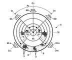
図1の表示制御部36は、定位解析部34による解析結果を表現する図2の定位設定画像Gを表示装置26に表示させる。図2に示すように、定位設定画像Gは、各周波数成分の音像の分布(以下「音像分布」という)を表現する音像分布画像50と、各チャネルの放音装置14を表象する5個の放音地点画像60(60C,60L,60R,60LS,60RS)とを含んで構成される。
The
音像分布画像50は、基準点P0を中心とする座標平面(以下「音像平面」という)内での音像分布を表現する円形状の画像である。基準点P0は、再生音の受聴者Hの位置(受聴点)に相当する。音像平面内では、基準点P0を中心とした半径方向が周波数を意味し、基準点P0を中心とした円周方向が定位方向を意味する。すなわち、基準点P0から半径方向に延在する任意の直線が周波数軸に相当し、基準点P0を中心とした任意の同心円が定位方向の座標軸に相当する。図2に図示された半径方向の直線DCは、基準点P0に位置する受聴者Hの正面方向を意味し、基準点P0を挟んで正面方向DCの反対側が受聴者Hの背面方向を意味する。したがって、正面方向DCに対して反時計回りに180°にわたる半円状の範囲が受聴者Hの左側(左前方から左後方)に相当し、正面方向DCに対して時計回りに180°にわたる半円状の範囲が受聴者Hの右側(右前方から右後方)に相当する。
The sound
各放音地点画像60は、音像分布画像50の周囲の領域のうち各放音装置14に対応する位置(基準点P0を中心とする円周上)に配置される。具体的には、放音装置14Cを表象する放音地点画像60Cは正面方向DCに配置され、放音装置14Lを表象する放音地点画像60Lは基準点P0の左前方(例えば正面方向DCに対して反時計回りに30°の方向)DLに配置され、放音装置14Rを表象する放音地点画像60Rは基準点P0の右前方(例えば正面方向DCに対して時計回りに30°の方向)DRに配置される。また、放音装置14LSを表象する放音地点画像60LSは基準点P0の左後方DLSに配置され、放音装置14RSを表象する放音地点画像60RSは基準点P0の右後方DRSに配置される。
Each sound emitting point image 60 is arranged at a position corresponding to each sound emitting device 14 (on the circumference centering on the reference point P0) in the region around the sound
表示制御部36は、音響信号Xのうち特定の区間(以下「表示対象区間」という)内の各周波数成分を表象する複数の音像図形Qを音像平面に配置する。表示対象区間は、音響信号Xのうち例えば利用者が入力装置28に対する操作で選択した1個以上の単位期間で構成される。表示対象区間内の音響信号Xのうち周波数F[k]の周波数成分に対応する音像図形Qは、音像平面内の半径方向に沿う複数の地点のうち周波数F[k]に対応する地点と、音像平面内の円周方向に沿う複数の地点のうち定位解析部34が周波数F[k]について算定した定位方向θ[k]に対応する地点とで規定される座標に位置する。すなわち、基準点P0を中心として周波数F[k]に対応する半径の円弧と、基準点P0から定位方向θ[k]に延在する直線との交差点に、周波数F[k]の周波数成分を表象する音像図形Qが配置される。以上の説明から理解されるように、音像平面内の各音像図形Qにより音響信号Xの各周波数成分の音像分布が表現される。すなわち、利用者は、音像分布画像50を視認することで音響信号Xの各周波数成分の周波数F[k]と定位方向θ[k]との関係(音像分布)を視覚的および直観的に確認することが可能である。なお、各周波数成分の音像図形Qの表示態様(例えば色彩や階調やサイズ等の視覚的に認識可能な性状)を各周波数成分の強度(例えば強度|XL[k]|および強度|XR[k]|の一方や両者の平均)に応じて可変に制御する構成も好適である。
The
各周波数成分の定位方向θ[k]は、左チャネルの音響信号XLと右チャネルの音響信号XRとを適用した数式(1)の演算で算定される。したがって、定位解析部34が算定した各定位方向θ[k]は、基準点P0の前方にて左前方DLと右前方DRとに挟まれた扇形の領域(以下「初期分布領域」という)A0内に包含される。すなわち、利用者からの指示が音像分布に反映されていない初期的な状態の音像分布画像50では、各周波数成分に対応する全部の音像図形Qが初期分布領域A0の内側に分布する。
The localization direction θ [k] of each frequency component is calculated by the calculation of Equation (1) using the left channel acoustic signal XL and the right channel acoustic signal XR. Accordingly, each localization direction θ [k] calculated by the
表示制御部36は、入力装置28に対する利用者からの指示に応じて音像平面内の初期分布領域A0を複数の操作対象領域Bに区分する。各操作対象領域Bは、初期分布領域A0を半径方向および円周方向に区分した円弧形(アーチ形)の領域である。具体的には、表示制御部36は、基準点P0を中心とする円弧状の各区分線SCを境界として初期分布領域A0を半径方向に複数の範囲(以下「周波数範囲」という)AFに区分し、基準点P0から半径方向に延在する直線状の各区分線SRを境界として初期分布領域A0を円周方向に複数の範囲(以下「定位範囲」という)APに区分する。各区分線SCの半径方向の位置(各周波数範囲AF)と各区分線SRの円周方向の位置(定位範囲AP)とは利用者からの指示に応じて可変に設定される。
The
各操作対象領域Bは、各区分線SRと各区分線SCとで包囲された領域である。すなわち、表示制御部36は、各区分線SCで画定された周波数範囲AFと各区分線SRで画定された定位範囲APとに対応した操作対象領域Bを利用者からの指示に応じて設定する。利用者は、初期分布領域A0のうち音響信号Xの所望の周波数成分(例えば所望の定位方向に定位する所望の音域の楽器音)を包含するように操作対象領域B(所望の周波数を包含する周波数範囲AFと所望の定位方向を包含する定位範囲AP)を指定する。
Each operation target area B is an area surrounded by each division line SR and each division line SC. That is, the
利用者は、入力装置28を適宜に操作する(例えばマウスでドラッグする)ことで音像平面内の任意の操作対象領域Bの移動を音響処理装置100に指示することが可能である。表示制御部36は、利用者から指示された操作対象領域B内の音像分布(複数の音像図形Qの集合)を利用者からの指示に応じて円周方向に移動させる。具体的には、図3に破線の矢印で図示した通り、初期分布領域A0内の各操作対象領域B内の音像分布が初期分布領域A0の外側の領域に円周方向に沿って任意の移動量だけ移動する。すなわち、音響信号Xの各周波数成分の定位方向θ[k]が、基準点P0の周囲の全方向(360°)から選択された任意の方向に操作対象領域B毎に変更される。
The user can instruct the
図1の信号処理部42は、音響信号Xの各周波数成分に対する信号処理で音響信号Y(YC,YL,YR,YLS,YRS)の各周波数成分(周波数スペクトル)をチャネル毎に生成する。具体的には、信号処理部42は、各チャネルの音響信号Yの各周波数成分の音像分布が、利用者からの指示(操作対象領域Bの移動)を反映した音像分布画像50で表現される音像分布に対応するように、音響信号Xの各周波数成分から音響信号Yのチャネル毎の各周波数成分を生成する。例えば、操作対象領域Bの移動後の音像分布画像50にて基準点P0の左後方DLSと右後方DRSとの間に定位方向θ[k]が位置する周波数F[k]の周波数成分(音像図形Qが基準点P0の後方に位置する周波数成分)については、音響信号Xのうち周波数F[k]の周波数成分が、変更後の定位方向θ[k]に応じた位相差および強度比で音響信号YLSおよび音響信号YRSの各々における周波数F[k]の周波数成分に分配される。同様に、基準点P0の左方(左前方DLと左後方DLSとの間)に変更後の定位方向θ[k]が位置する周波数F[k]の周波数成分については、音響信号Xのうち周波数F[k]の周波数成分が、変更後の定位方向θ[k]に応じた位相差および強度比で音響信号YLおよび音響信号YLSの各々における周波数F[k]の周波数成分に分配される。
The
波形合成部44は、信号処理部42がチャネル毎に生成した周波数成分から各チャネルの音響信号Y(YC,YL,YR,YLS,YRS)を生成する。具体的には、波形合成部44は、音響信号YCの各周波数成分(周波数スペクトル)に対する短時間逆フーリエ変換で生成した時間領域信号を前後の単位期間にて相互に連結することで音響信号YCを生成する。各チャネルの音響信号Yが各放音装置14に供給されることで音波として再生される。したがって、各操作対象領域Bの移動後の音像分布画像50で指定された定位位置θ[k]に再生音の各周波数成分の音像を定位させた音場が受聴者Hの周囲に形成される。
The
以上に説明した第1実施形態では、周波数範囲AFと定位範囲APとで音像平面に画定される操作対象領域B内の各周波数成分の定位方向θ[k](音像分布)が利用者からの指示に応じて変更される。すなわち、音響信号Xのうち特定の周波数成分についてのみ選択的に定位方向θ[k]が変更される。したがって、非特許文献1の技術と比較して、各周波数成分の定位方向θ[k]を精緻に調整することが可能である。また、受聴者Hに相当する基準点P0を中心とした円周方向に操作対象領域B内の音像分布が移動するから、音像平面内の音像分布を視覚的および直観的に把握しながら利用者が各周波数成分の定位方向θ[k]を容易に調整できるという利点もある。 In the first embodiment described above, the localization direction θ [k] (sound image distribution) of each frequency component in the operation target area B defined on the sound image plane by the frequency range AF and the localization range AP is determined from the user. Changed according to instructions. That is, the localization direction θ [k] is selectively changed only for a specific frequency component in the acoustic signal X. Therefore, compared with the technique of Non-Patent Document 1, it is possible to finely adjust the localization direction θ [k] of each frequency component. Further, since the sound image distribution in the operation target area B moves in the circumferential direction around the reference point P0 corresponding to the listener H, the user can grasp the sound image distribution in the sound image plane visually and intuitively. However, there is an advantage that the localization direction θ [k] of each frequency component can be easily adjusted.
また、第1実施形態では、操作対象領域Bを規定する周波数範囲AFおよび定位範囲APが利用者からの指示に応じて可変に設定される。したがって、所望の方向に定位する所望の音域の音源からの音響(例えば収録時に特定の方向に配置された楽器の演奏音)についてのみ選択的に定位方向θ[k]を変更するといった多様かつ精緻な調整が可能である。 In the first embodiment, the frequency range A F and the localization range AP that define the operation target region B are variably set according to an instruction from the user. Therefore, the localization direction θ [k] is selectively changed only for sound from a sound source in a desired range localized in a desired direction (for example, a performance sound of an instrument arranged in a specific direction during recording). Adjustment is possible.
<第2実施形態>
本発明の第2実施形態を以下に説明する。なお、以下に例示する各形態において作用や機能が第1実施形態と同様である要素については、第1実施形態の説明で参照した符号を流用して各々の詳細な説明を適宜に省略する。
Second Embodiment
A second embodiment of the present invention will be described below. In addition, about the element which an effect | action and function are the same as that of 1st Embodiment in each form illustrated below, the reference | standard referred by description of 1st Embodiment is diverted and each detailed description is abbreviate | omitted suitably.
図4は、第2実施形態における定位設定画像Gの模式図である。図4に示すように、第2実施形態の表示制御部36が表示装置26に表示させる音像分布画像50は、各操作対象領域Bの強度値Eを第1実施形態の音像分布画像50に追加した画像である。各強度値Eは、操作対象領域B内の各周波数成分の平均強度(音量)の数値であり、操作対象領域Bの内部または近傍に配置される。
FIG. 4 is a schematic diagram of a localization setting image G in the second embodiment. As shown in FIG. 4, the sound
利用者は、入力装置28を適宜に操作する(例えば所望の操作対象領域Bをマウスやタッチパネル等の入力装置28で選択した場合に表示されるスライダ等の操作子を操作する)ことで、所望の操作対象領域Bの強度値Eの変更を指示することが可能である。表示制御部36は、入力装置28に対する利用者からの指示に応じて各操作対象領域Bの強度値Eを変更する。各強度値Eは、利用者からの指示に応じた操作対象領域Bの移動後も操作対象領域Bの内部または近傍に配置される。信号処理部42は、音響信号Yのうち操作対象領域B内の各周波数成分の強度(振幅)を、その操作対象領域Bに指定された強度値Eに応じて制御する。
The user appropriately operates the input device 28 (for example, by operating an operator such as a slider displayed when the desired operation target area B is selected by the
第2実施形態においても第1実施形態と同様の効果が実現される。また、第2実施形態では、音像平面内の音像分布を強度値Eとともに視覚的および直観的に把握しながら利用者が各周波数成分の強度値Eを容易に調整できるという利点がある。 In the second embodiment, the same effect as in the first embodiment is realized. Further, the second embodiment has an advantage that the user can easily adjust the intensity value E of each frequency component while visually and intuitively grasping the sound image distribution in the sound image plane together with the intensity value E.
<第3実施形態>
図5は、第3実施形態における定位設定画像Gの模式図である。図5に矢印で図示した通り、第3実施形態の表示制御部36は、音像分布画像50に対する各放音地点画像60の位置を可変に制御する。利用者は、入力装置28を適宜に操作することで、所望の放音地点画像60の移動を指示することが可能である。表示制御部36は、入力装置28に対する利用者からの指示に応じて、基準点P0を中心とした円周方向に各放音地点画像60を移動させる。
<Third Embodiment>
FIG. 5 is a schematic diagram of a localization setting image G in the third embodiment. As illustrated by arrows in FIG. 5, the
信号処理部42は、放音地点画像60の各位置に配置された放音装置14が各チャネルの音響信号Yを再生した場合の各周波数成分の音像分布が、音像分布画像50で表現される音像分布に対応するように、音響信号Xの各周波数成分から各チャネルの音響信号Yの各周波数成分を生成する。具体的には、放音地点画像60の各位置と各周波数成分の定位方向θ[k]との位置関係に応じた位相差および強度比で音響信号Xの各周波数F[k]の周波数成分が各チャネルの音響信号Yに分配される。
In the
第3実施形態においても第1実施形態と同様の効果が実現される。また、第3実施形態では、利用者からの指示に応じて調整された各放音地点画像60の位置が音響信号Yの生成に反映されるから、各放音装置14の実際の配置位置に応じて放音地点画像60を調整することで、音像分布画像50にて表現された音像分布を実際の音響空間にて忠実に再現することが可能である。
In the third embodiment, the same effect as in the first embodiment is realized. In the third embodiment, since the position of each sound emitting point image 60 adjusted according to the instruction from the user is reflected in the generation of the acoustic signal Y, the actual arrangement position of each sound emitting device 14 is reflected. By adjusting the sound emission point image 60 accordingly, the sound image distribution expressed by the sound
なお、以上の説明では、各放音地点画像60の位置を利用者が個別に変更する場合を例示したが、各放音地点画像60について相異なる位置を指定する複数の位置情報(テンプレート)を記憶装置24に事前に格納した構成も採用され得る。複数の位置情報のうち利用者が選択した位置情報に応じて各放音地点画像60の位置が設定される。
In the above description, the case where the user individually changes the position of each sound emission point image 60 is exemplified. However, a plurality of pieces of position information (templates) for specifying different positions for each sound emission point image 60 are provided. A configuration stored in advance in the
<変形例>
以上に例示した各形態には様々な変形が加えられる。具体的な変形の態様を以下に例示する。以下の例示から任意に選択された2以上の態様は適宜に併合され得る。
<Modification>
Various modifications can be made to each of the forms exemplified above. Specific modifications are exemplified below. Two or more aspects arbitrarily selected from the following examples can be appropriately combined.
(1)前述の各形態では、操作対象領域Bを円周方向に移動する場合を例示したが、利用者からの指示に応じて表示制御部36が操作対象領域Bを半径方向(周波数軸方向)に移動することも可能である。操作対象領域B(各周波数成分の音像分布)の半径方向の移動は周波数成分の音高の変更(ピッチシフト)を意味する。したがって、信号処理部42は、各操作対象領域B内の各周波数成分の音高を操作対象領域Bの半径方向の移動量に応じて調整することで各チャネルの音響信号Yを生成する。
(1) In each of the above-described embodiments, the case where the operation target region B is moved in the circumferential direction is illustrated, but the
また、図6に示すように、利用者からの指示に応じて操作対象領域Bを円周方向に伸縮することも可能である。図2に例示された定位設定画像Gのうちの1個の操作対象領域Bを円周方向に伸長した場合が図6では例示されている。表示制御部36は、操作対象領域Bの伸縮に連動して操作対象領域B内の音像分布を伸縮する。すなわち、操作対象領域Bが円周方向に伸長された場合には操作対象領域B内の各音像図形Qの円周方向の間隔が伸長率に応じて拡大され、操作対象領域Bが円周方向に収縮された場合には操作対象領域B内の各音像図形Qの円周方向の間隔が縮小率に応じて縮小される。操作対象領域Bの伸縮の前後に各操作対象領域Bは利用者からの指示に応じて円周方向(または半径方向)に移動される。例えば、操作対象領域Bを略直線状の形状(各音像図形Qが直線状に配列する形状)まで収縮して円周方向に適宜に移動させることで、操作対象領域B内の各周波数成分の再生音が特定の1個の放音装置14のみから放音されるように音像分布を制御することが可能である。
In addition, as shown in FIG. 6, the operation target area B can be expanded and contracted in the circumferential direction in accordance with an instruction from the user. FIG. 6 illustrates a case where one operation target region B in the localization setting image G illustrated in FIG. 2 is extended in the circumferential direction. The
(2)前述の各形態では全部の周波数成分を各放音装置14から再生したが、音像分布画像50から選択された1個以上の操作対象領域B(例えば利用者が選択した操作対象領域B)内の周波数成分のみを選択的に各放音装置14から再生することも可能である。 (2) Although all frequency components are reproduced from each sound emitting device 14 in each of the above-described embodiments, one or more operation target regions B selected from the sound image distribution image 50 (for example, the operation target region B selected by the user). It is also possible to selectively reproduce only the frequency components in () from each sound emitting device 14.
(3)前述の各形態では、各放音装置14に対応する5チャネルの音響信号Y(YC,YL,YR,YLS,YRS)を2チャネルの音響信号X(XL,XR)から生成したが、音響信号Xや音響信号Yのチャネル数は適宜に変更される。例えば、3チャネル以上(例えば5チャネル)の音響信号Xを音響処理装置100に供給する構成では、各チャネルの音響信号Xから各周波数成分の定位方向θ[k]が算定される。したがって、初期分布領域A0は、基準点P0を中心とした全周にわたる領域となる。また、3チャネル以上の音響信号Xのうち音響処理装置100による処理対象となるチャネル数を例えば利用者からの指示に応じて可変に設定する構成も好適である。
(3) In each of the above-described embodiments, the 5-channel acoustic signal Y (YC, YL, YR, YLS, YRS) corresponding to each sound emitting device 14 is generated from the 2-channel acoustic signal X (XL, XR). The number of channels of the acoustic signal X and the acoustic signal Y is changed as appropriate. For example, in the configuration in which the acoustic signal X of 3 channels or more (for example, 5 channels) is supplied to the
また、前述の各形態と同様に生成された5チャネルの音響信号Yに頭部伝達関数を畳込むことで、前述の各形態と同様の音場を仮想的に形成する2チャネルの音響信号を生成することも可能である。また、前述の各形態では、音響信号Yの全部のチャネルについて各周波数成分の定位方向を制御したが、特定のチャネルを定位方向の調整対象から除外することも可能である。例えば、映画等の映像作品では正面方向の音響信号YCが登場人物の台詞等の音声を含む場合が多く、歌唱曲の収録音では正面方向の音響信号YCが歌唱音(メインボーカル)を含む場合が多いという傾向がある。以上の傾向のもとでは、音響信号YCを信号処理部42による調整対象から除外して所期の方向に定位させる構成が好適である。
Also, by convolving the head-related transfer function with the 5-channel acoustic signal Y generated in the same manner as in the above-described embodiments, a 2-channel acoustic signal that virtually forms a sound field similar to those in the above-described embodiments is obtained. It is also possible to generate. Further, in each of the above-described embodiments, the localization direction of each frequency component is controlled for all the channels of the acoustic signal Y, but it is also possible to exclude a specific channel from the localization direction adjustment target. For example, in the case of a video work such as a movie, the front acoustic signal YC often includes voices such as characters of the characters, and the recorded sound of the song includes the front acoustic signal YC including the singing sound (main vocal). There is a tendency that there are many. Under the above tendency, a configuration in which the acoustic signal YC is excluded from the adjustment target by the
モノラル(1チャネル)の音響信号Xを音響処理装置100に供給することも可能である。モノラルの音響信号Xを音響処理装置100に供給する場合、音響信号Xを2チャネルに分配して各周波数成分の定位方向θ[k]を算定することが可能である。以上の構成では、定位設定画像Gの初期状態では、各周波数成分に対応する複数の音像図形Qが正面方向DCに沿って直線状に配列する。また、モノラルの音響信号Xをステレオの音響信号X(XL,XR)に変換してから処理することも可能である。例えば、ステレオリバーブ等の音響効果を音響信号Xに付与する(更には各チャネルのバランスを調整する)ことでステレオの音響信号Xが生成される。
It is also possible to supply a monaural (one channel) acoustic signal X to the
(4)前述の各形態では、各放音装置14が内側の受聴者Hに放音する場合を例示したが、放音面が外側を向くように各放音装置14を配置することで各放音装置14の周囲に音場を形成する場合にも本発明を適用することが可能である。放音装置14を外向きに配置した場合の定位設定画像Gでは、基準点P0に対して外向きの各放音装置14を表象する放音地点画像60が配置され、各放音地点画像60の周囲の音像平面に各音像図形Qが配置される。 (4) In each of the above-described embodiments, the case where each sound emitting device 14 emits sound to the inner listener H is exemplified, but each sound emitting device 14 is arranged such that the sound emitting surface faces outward. The present invention can also be applied when a sound field is formed around the sound emitting device 14. In the localization setting image G when the sound emitting devices 14 are arranged outward, sound emitting point images 60 representing the sound emitting devices 14 facing outward with respect to the reference point P0 are arranged. Each sound image figure Q is arranged on the sound image plane around the.
(5)前述の各形態では、初期分布領域A0を半径方向および円周方向に複数の操作対象領域Bに区分したが、各操作対象領域Bの選定方法や各操作対象領域Bの形状は以上の例示に限定されない。例えば、入力装置28に対する利用者からの指示に応じて任意の形状の操作対象領域Bを設定する構成や、複数の操作対象領域Bが半径方向または周波数方向に相互に重複する構成も採用され得る。
(5) In each embodiment described above, the initial distribution area A0 is divided into a plurality of operation target areas B in the radial direction and the circumferential direction. However, the selection method of each operation target area B and the shape of each operation target area B are as described above. It is not limited to the illustration. For example, a configuration in which an operation target region B having an arbitrary shape is set in accordance with an instruction from the user to the
(6)図7に例示したように、各操作対象領域B内の音像分布を維持したまま各操作対象領域B内の音像分布を位置に複製(コピー)することも可能である。第2実施形態で例示した強度値Eは、複製元の操作対象領域Bと複製先の操作対象領域Bとの双方に配置される。信号処理部42は、各操作対象領域Bの複製後の音像分布に対応するように音響信号Yを生成する。ただし、各操作対象領域B内の周波数成分を単純に複製しただけでは音響信号Yの音量が音響信号Xと比較して増加して聴感的に不自然な印象となる可能性がある。そこで、操作対象領域Bが複製された場合でも音響信号Yの音量が過度に増加しないように、複製元の操作対象領域Bの各周波数成分の強度と複製先の操作対象領域Bの各周波数成分の強度とを調整(低減)することも可能である。例えば、信号処理部42は、複製元の操作対象領域B内の各周波数成分の強度に対して例えば0.9程度の所定の調整値(ゲイン)を乗算し、複製先の操作対象領域B内の各周波数成分の強度に対して複製元の調整値を下回る調整値(例えば0.4程度)を乗算する。以上の説明から理解されるように、本発明における音像分布の「移動」は、操作前の音像分布を維持しない狭義の「移動」と、操作前の音像分布を維持する「複製」との双方を包含する概念である。なお、操作対象領域B(音像分布)の複製は複数回にわたり反復され得る。
(6) As illustrated in FIG. 7, the sound image distribution in each operation target region B can be copied (copied) to the position while the sound image distribution in each operation target region B is maintained. The intensity value E exemplified in the second embodiment is arranged in both the duplication source operation target area B and the duplication destination operation target area B. The
なお、操作対象領域B内の音像分布を他の位置に複製する場合、複製先の操作対象領域B内の各周波数成分に対して信号処理部42が各種の音響効果を付与することも可能である。例えば、0.1秒程度のディレイやリバーブ等の音響効果を信号処理部42が複製先の操作対象領域内の各周波数成分に付与する構成によれば、利用者による簡単な操作で音場の拡がり感を増加させることが可能である。また、複製先の操作対象領域B内の各周波数成分から信号処理部42が残響成分を抽出する構成も好適である。例えば、基準点P0の前方に位置する操作対象領域Bを基準点P0の後方に複製し、複製先の操作対象領域B内の各周波数成分から残響成分を抽出したうえで複製元の操作対象領域B内の各周波数成分とともに再生すれば、音響ホール等の音響空間と同様の音場の拡がり感を受聴者Hに知覚させることが可能である。なお、各周波数成分から残響成分を抽出する処理には公知の技術(残響抽出技術,残響抑圧技術)を任意に採用することが可能である。残響抑圧技術を利用する場合、例えば、複製元の操作対象領域B内の各周波数成分に対する残響抑圧で直接音成分を推定し、複製元の操作対象領域B内の各周波数成分から直接音成分を減算することで操作対象領域B内の残響成分を推定することが可能である。なお、複製元の操作対象領域B内の各周波数成分に対する残響抑圧の有無は不問である。
When the sound image distribution in the operation target area B is duplicated at another position, the
(7)前述の各形態では、各操作対象領域B内の音像分布を維持したまま移動させたが、操作対象領域Bの移動(複製)の前後にわたる音像分布は厳密に合致している必要はない。例えば、操作対象領域Bを基準点P0に対して反対側に移動した場合に、移動後の操作対象領域B内の音像分布を、移動前の操作対象領域B内の音像分布を円周方向に反転させた分布に設定することが可能である。以上の構成によれば、利用者による簡単な操作で音場の拡がり感を増加させることが可能である。 (7) In the above-described embodiments, the sound image distribution in each operation target area B is moved while maintaining the sound image distribution. However, the sound image distribution before and after the movement (duplication) of the operation target area B needs to be strictly matched. Absent. For example, when the operation target area B is moved to the opposite side with respect to the reference point P 0, the sound image distribution in the operation target area B after the movement is changed, and the sound image distribution in the operation target area B before the movement is set in the circumferential direction. It is possible to set an inverted distribution. According to the above configuration, it is possible to increase the sense of expansion of the sound field with a simple operation by the user.
(8)音像分布画像50の外形は円形に限定されない。例えば、扇形(半円形や3/4円等)や楕円形の音像分布画像50を表示した場合でも前述の各形態が同様に採用され得る。また、音像分布画像50の外形を多角形状(例えば四角形や三角形)とすることも可能である。例えば、各放音装置14が実際に設置される音響空間を表象する長方形状の音像分布画像50を表示する構成が好適である。以上の説明から理解されるように、音像分布画像50は、音像平面内での各周波数成分の音像分布を表現する画像として包括され、音像分布画像の外形は任意である。また、前述の各形態の例示から理解されるように、音像平面は、典型的には、半径方向(基準点P0から放射状に延在する直線の方向)が周波数に対応し、円周方向(基準点P0の周囲の円弧(楕円の円弧も包含する)の方向)が定位方向に対応する平面である。
(8) The outer shape of the sound
(9)前述の各形態では、音像分布画像50を平面画像として表示したが、音像分布画像50を例えば球状や立方体状(例えば各放音装置14が設置される音響空間の内部形状)の立体画像として表示装置26に表示することも可能である。音像分布画像50を表現する立体を横断するとともに基準点P0を通過する平面が音像平面に相当する。音像分布画像50を立体画像として表示する構成では、基準点P0に対する左右方向の音像定位に加えて基準点P0に対する上下方向の音像定位も調整することが可能である。したがって、例えば9.1チャネルのサラウンドシステムのように受聴者Hの上下方向にも音像を定位させる構成のもとで格別に好適である。
(9) In each of the above embodiments, the sound
(10)各放音地点画像60を配置する位置の選定方法は任意である。例えば、音響信号Yのチャネル数(放音地点画像60の個数)に応じて各放音地点画像60の位置を自動的に選定する構成が好適である。例えば、ITU−R BS.775−1の規格に準拠した各位置に放音地点画像60を配置する構成や、各放音地点画像60の位置を規定する複数のテンプレートのうち利用者が選択したテンプレートが規定する各位置に放音地点画像60を配置する構成が好適である。 (10) The selection method of the position which arrange | positions each sound emission point image 60 is arbitrary. For example, a configuration in which the position of each sound emission point image 60 is automatically selected according to the number of channels of the acoustic signal Y (number of sound emission point images 60) is suitable. For example, the user has selected a configuration in which the sound emission point images 60 are arranged at positions corresponding to the standard of ITU-R BS.775-1 or a plurality of templates that define the positions of the sound emission point images 60. A configuration in which the sound emission point image 60 is arranged at each position defined by the template is suitable.
(11)第2実施形態では、操作対象領域B内の各周波数成分の強度値Eを表示したが、操作対象領域B内の各周波数成分を調整する構成(例えば各周波数成分に音響効果を付与する構成)では、強度値Eに代えて(または強度値Eとともに)、各周波数成分の調整のパラメータを操作対象領域Bに対応して表示することも可能である。 (11) In the second embodiment, the intensity value E of each frequency component in the operation target region B is displayed. However, a configuration for adjusting each frequency component in the operation target region B (for example, imparting an acoustic effect to each frequency component) In this configuration, instead of the intensity value E (or together with the intensity value E), it is also possible to display parameters for adjusting each frequency component corresponding to the operation target region B.
(12)前述の各形態では、定位設定画像Gに対する利用者からの指示に応じて音響信号Xを処理する音響処理装置100を例示したが、音響信号Xの音像分布を解析して結果(定位設定画像G)を表示する音響解析装置としても本発明は実現され得る。音響解析装置は、音響信号Xの各周波数成分の定位方向θ[k]を算定する定位解析部34と、各周波数成分の音像分布を表現する定位設定画像Gを表示装置26に表示させる表示制御部36とを含んで構成される。以上の説明から理解されるように、前述の各形態にて例示した信号処理部42は省略され得る。
(12) In each of the above-described embodiments, the
100……音響処理装置、12……信号供給装置、14……放音装置、22……演算処理装置、24……記憶装置、26……表示装置、28……入力装置、32……周波数分析部、34……定位解析部、36……表示制御部、42……信号処理部、44……波形合成部、G……定位設定画像、50……音像分布画像、60(60C,60L,60R,60LS,60RS)……放音地点画像、B……操作対象領域。
DESCRIPTION OF
Claims (5)
基準点を中心とした半径方向が周波数に対応するとともに円周方向が定位方向に対応する音像平面内での前記第1音響信号の各周波数成分の音像分布を表現する音像分布画像を表示装置に表示させる手段であって、前記音像平面のうち前記半径方向に設定された周波数範囲と前記円周方向に設定された定位範囲とに対応する操作対象領域内の音像分布を利用者からの指示に応じて円周方向に移動させる表示制御手段と、
前記第2音響信号の各周波数成分の音像分布が、前記操作対象領域の移動後の音像分布画像が表現する音像分布に対応するように、前記第1音響信号から前記第2音響信号を生成する信号処理手段と
を具備する音響処理装置。 An apparatus for generating a second acoustic signal of a plurality of channels from a first acoustic signal,
A sound image distribution image representing a sound image distribution of each frequency component of the first acoustic signal in a sound image plane in which the radial direction centered on the reference point corresponds to the frequency and the circumferential direction corresponds to the localization direction is displayed on the display device. A means for displaying a sound image distribution in an operation target region corresponding to a frequency range set in the radial direction and a localization range set in the circumferential direction in the sound image plane, based on an instruction from a user; Display control means for moving in the circumferential direction accordingly,
The second sound signal is generated from the first sound signal so that the sound image distribution of each frequency component of the second sound signal corresponds to the sound image distribution represented by the sound image distribution image after movement of the operation target region. A sound processing apparatus comprising: signal processing means.
請求項1の音響処理装置。 The display control means sets the operation target area defined inside an initial distribution area in which each frequency component of the first acoustic signal is distributed in the sound image plane according to an instruction from a user. The sound processing apparatus according to claim 1.
請求項1または請求項2の音響処理装置。 The sound processing apparatus according to claim 1, wherein the display control unit variably sets the frequency range and the localization range according to an instruction from a user.
前記信号処理手段は、前記操作対象領域内の各周波数成分の強度を、当該操作対象領域に対応する強度値に応じて調整する
請求項1から請求項3の何れかの音響処理装置。 The display control means arranges the intensity value of each frequency component in the operation target area at a position corresponding to the operation target area and changes it according to an instruction from the user,
The acoustic processing apparatus according to claim 1, wherein the signal processing unit adjusts the intensity of each frequency component in the operation target area according to an intensity value corresponding to the operation target area.
前記信号処理手段は、前記放音地点画像の各位置に配置された放音装置が前記第2音響信号を再生した場合の各周波数成分の音像分布が、前記音像分布画像が表現する音像分布に対応するように、前記第1音響信号から前記第2音響信号を生成する
請求項1から請求項4の何れかの音響処理装置。 The display control means arranges sound emitting point images representing sound emitting devices of the respective channels of the second acoustic signal at respective positions in the circumferential direction around the reference point, and also releases the sound emitting points in the circumferential direction. The position of the sound spot image is variably set according to the instruction from the user,
The signal processing means converts the sound image distribution of each frequency component when a sound emitting device arranged at each position of the sound emitting point image reproduces the second acoustic signal into a sound image distribution represented by the sound image distribution image. The acoustic processing device according to claim 1, wherein the second acoustic signal is generated from the first acoustic signal so as to correspond.
Priority Applications (1)
| Application Number | Priority Date | Filing Date | Title |
|---|---|---|---|
| JP2012068131A JP5915308B2 (en) | 2012-03-23 | 2012-03-23 | Sound processing apparatus and sound processing method |
Applications Claiming Priority (1)
| Application Number | Priority Date | Filing Date | Title |
|---|---|---|---|
| JP2012068131A JP5915308B2 (en) | 2012-03-23 | 2012-03-23 | Sound processing apparatus and sound processing method |
Publications (2)
| Publication Number | Publication Date |
|---|---|
| JP2013201564A true JP2013201564A (en) | 2013-10-03 |
| JP5915308B2 JP5915308B2 (en) | 2016-05-11 |
Family
ID=49521452
Family Applications (1)
| Application Number | Title | Priority Date | Filing Date |
|---|---|---|---|
| JP2012068131A Expired - Fee Related JP5915308B2 (en) | 2012-03-23 | 2012-03-23 | Sound processing apparatus and sound processing method |
Country Status (1)
| Country | Link |
|---|---|
| JP (1) | JP5915308B2 (en) |
Cited By (5)
| Publication number | Priority date | Publication date | Assignee | Title |
|---|---|---|---|---|
| JP2015149549A (en) * | 2014-02-05 | 2015-08-20 | 日本放送協会 | Multiple sound source arrangement device, multiple sound source arrangement method |
| KR101608599B1 (en) * | 2014-11-28 | 2016-04-01 | 한국산업은행 | Method of processing 3d audio apparatus performing the same and media storing the same |
| JP2016134768A (en) * | 2015-01-20 | 2016-07-25 | ヤマハ株式会社 | Audio signal processor |
| WO2017163940A1 (en) * | 2016-03-23 | 2017-09-28 | ヤマハ株式会社 | Sound processing method and sound processing device |
| WO2019163013A1 (en) * | 2018-02-21 | 2019-08-29 | 株式会社ソシオネクスト | Audio signal processing device, audio adjustment method, and program |
Citations (7)
| Publication number | Priority date | Publication date | Assignee | Title |
|---|---|---|---|---|
| JPH04296200A (en) * | 1991-03-26 | 1992-10-20 | Mazda Motor Corp | Acoustic equipment |
| JP2000314657A (en) * | 1999-04-28 | 2000-11-14 | Yamaha Corp | Frequency analyzer |
| JP2004312355A (en) * | 2003-04-07 | 2004-11-04 | Yamaha Corp | Sound field controller |
| JP2006101248A (en) * | 2004-09-30 | 2006-04-13 | Victor Co Of Japan Ltd | Sound field compensation device |
| JP2007201818A (en) * | 2006-01-26 | 2007-08-09 | Sony Corp | Apparatus, method and program for processing audio signal |
| US20080019531A1 (en) * | 2006-07-21 | 2008-01-24 | Sony Corporation | Audio signal processing apparatus, audio signal processing method, and audio signal processing program |
| JP2011158674A (en) * | 2010-01-29 | 2011-08-18 | Roland Corp | User interface apparatus |
-
2012
- 2012-03-23 JP JP2012068131A patent/JP5915308B2/en not_active Expired - Fee Related
Patent Citations (9)
| Publication number | Priority date | Publication date | Assignee | Title |
|---|---|---|---|---|
| JPH04296200A (en) * | 1991-03-26 | 1992-10-20 | Mazda Motor Corp | Acoustic equipment |
| JP2000314657A (en) * | 1999-04-28 | 2000-11-14 | Yamaha Corp | Frequency analyzer |
| JP2004312355A (en) * | 2003-04-07 | 2004-11-04 | Yamaha Corp | Sound field controller |
| JP2006101248A (en) * | 2004-09-30 | 2006-04-13 | Victor Co Of Japan Ltd | Sound field compensation device |
| JP2007201818A (en) * | 2006-01-26 | 2007-08-09 | Sony Corp | Apparatus, method and program for processing audio signal |
| US20070189551A1 (en) * | 2006-01-26 | 2007-08-16 | Tadaaki Kimijima | Audio signal processing apparatus, audio signal processing method, and audio signal processing program |
| US20080019531A1 (en) * | 2006-07-21 | 2008-01-24 | Sony Corporation | Audio signal processing apparatus, audio signal processing method, and audio signal processing program |
| JP2008028700A (en) * | 2006-07-21 | 2008-02-07 | Sony Corp | Audio signal processor, audio signal processing method, and audio signal processing program |
| JP2011158674A (en) * | 2010-01-29 | 2011-08-18 | Roland Corp | User interface apparatus |
Cited By (10)
| Publication number | Priority date | Publication date | Assignee | Title |
|---|---|---|---|---|
| JP2015149549A (en) * | 2014-02-05 | 2015-08-20 | 日本放送協会 | Multiple sound source arrangement device, multiple sound source arrangement method |
| KR101608599B1 (en) * | 2014-11-28 | 2016-04-01 | 한국산업은행 | Method of processing 3d audio apparatus performing the same and media storing the same |
| JP2016134768A (en) * | 2015-01-20 | 2016-07-25 | ヤマハ株式会社 | Audio signal processor |
| WO2017163940A1 (en) * | 2016-03-23 | 2017-09-28 | ヤマハ株式会社 | Sound processing method and sound processing device |
| US10708705B2 (en) | 2016-03-23 | 2020-07-07 | Yamaha Corporation | Audio processing method and audio processing apparatus |
| US10972856B2 (en) | 2016-03-23 | 2021-04-06 | Yamaha Corporation | Audio processing method and audio processing apparatus |
| WO2019163013A1 (en) * | 2018-02-21 | 2019-08-29 | 株式会社ソシオネクスト | Audio signal processing device, audio adjustment method, and program |
| JPWO2019163013A1 (en) * | 2018-02-21 | 2021-02-04 | 株式会社ソシオネクスト | Audio signal processor, audio adjustment method and program |
| US11212634B2 (en) | 2018-02-21 | 2021-12-28 | Socionext Inc. | Sound signal processing device, sound adjustment method, and medium |
| JP7115535B2 (en) | 2018-02-21 | 2022-08-09 | 株式会社ソシオネクスト | AUDIO SIGNAL PROCESSING DEVICE, SOUND ADJUSTMENT METHOD AND PROGRAM |
Also Published As
| Publication number | Publication date |
|---|---|
| JP5915308B2 (en) | 2016-05-11 |
Similar Documents
| Publication | Publication Date | Title |
|---|---|---|
| JP5285626B2 (en) | Speech spatialization and environmental simulation | |
| JP5526107B2 (en) | Apparatus for determining spatial output multi-channel audio signals | |
| KR101341523B1 (en) | Method to generate multi-channel audio signals from stereo signals | |
| EP2648426B1 (en) | Apparatus for changing an audio scene and method therefor | |
| JP5449330B2 (en) | Angle-dependent motion apparatus or method for obtaining a pseudo-stereoscopic audio signal | |
| JP5915308B2 (en) | Sound processing apparatus and sound processing method | |
| KR102119240B1 (en) | Method for up-mixing stereo audio to binaural audio and apparatus using the same | |
| US20210076152A1 (en) | Controlling rendering of a spatial audio scene | |
| Ziemer | Wave field synthesis | |
| CN104969571A (en) | Method for rendering a stereo signal | |
| WO2022248729A1 (en) | Stereophonic audio rearrangement based on decomposed tracks | |
| WO2018193163A1 (en) | Enhancing loudspeaker playback using a spatial extent processed audio signal | |
| US7330552B1 (en) | Multiple positional channels from a conventional stereo signal pair | |
| James et al. | 2D and 3D timbral spatialisation: spatial motion, immersiveness, and notions of space | |
| GB2561844A (en) | Spatial audio processing | |
| JP2013172231A (en) | Audio mixing device | |
| Gottfried | Studies on the compositional use of space | |
| JP5915249B2 (en) | Sound processing apparatus and sound processing method | |
| US11924623B2 (en) | Object-based audio spatializer | |
| US11665498B2 (en) | Object-based audio spatializer | |
| Lynch | Space in multi-channel electroacoustic music: developing sound spatialisation techniques for composing multi-channel electroacoustic music with emphasis on spatial attribute perception | |
| Tom | Automatic mixing systems for multitrack spatialization based on unmasking properties and directivity patterns | |
| Deppisch et al. | Browser Application for Virtual Audio Walkthrough. | |
| Hakala | Synthesis of spatially extended sources in virtual reality audio | |
| Härmä et al. | Spatial track transition effects for headphone listening |
Legal Events
| Date | Code | Title | Description |
|---|---|---|---|
| A621 | Written request for application examination |
Free format text: JAPANESE INTERMEDIATE CODE: A621 Effective date: 20150122 |
|
| RD04 | Notification of resignation of power of attorney |
Free format text: JAPANESE INTERMEDIATE CODE: A7424 Effective date: 20150410 |
|
| A977 | Report on retrieval |
Free format text: JAPANESE INTERMEDIATE CODE: A971007 Effective date: 20150605 |
|
| A131 | Notification of reasons for refusal |
Free format text: JAPANESE INTERMEDIATE CODE: A131 Effective date: 20150630 |
|
| A521 | Request for written amendment filed |
Free format text: JAPANESE INTERMEDIATE CODE: A523 Effective date: 20150724 |
|
| TRDD | Decision of grant or rejection written | ||
| A01 | Written decision to grant a patent or to grant a registration (utility model) |
Free format text: JAPANESE INTERMEDIATE CODE: A01 Effective date: 20160308 |
|
| A61 | First payment of annual fees (during grant procedure) |
Free format text: JAPANESE INTERMEDIATE CODE: A61 Effective date: 20160321 |
|
| R151 | Written notification of patent or utility model registration |
Ref document number: 5915308 Country of ref document: JP Free format text: JAPANESE INTERMEDIATE CODE: R151 |
|
| LAPS | Cancellation because of no payment of annual fees |