JP2013200921A - Recording device and stray light signal component cancellation method - Google Patents
Recording device and stray light signal component cancellation method Download PDFInfo
- Publication number
- JP2013200921A JP2013200921A JP2012068843A JP2012068843A JP2013200921A JP 2013200921 A JP2013200921 A JP 2013200921A JP 2012068843 A JP2012068843 A JP 2012068843A JP 2012068843 A JP2012068843 A JP 2012068843A JP 2013200921 A JP2013200921 A JP 2013200921A
- Authority
- JP
- Japan
- Prior art keywords
- light
- signal
- recording
- stray light
- unit
- Prior art date
- Legal status (The legal status is an assumption and is not a legal conclusion. Google has not performed a legal analysis and makes no representation as to the accuracy of the status listed.)
- Pending
Links
Images


Classifications
-
- G—PHYSICS
- G11—INFORMATION STORAGE
- G11B—INFORMATION STORAGE BASED ON RELATIVE MOVEMENT BETWEEN RECORD CARRIER AND TRANSDUCER
- G11B7/00—Recording or reproducing by optical means, e.g. recording using a thermal beam of optical radiation by modifying optical properties or the physical structure, reproducing using an optical beam at lower power by sensing optical properties; Record carriers therefor
- G11B7/004—Recording, reproducing or erasing methods; Read, write or erase circuits therefor
- G11B7/0045—Recording
- G11B7/00458—Verification, i.e. checking data during or after recording
Abstract
Description
本技術は、光記録媒体に対する記録を行う記録装置に関するものであり、特に記録光としての第1の光と該第1の光とは異なる第2の光とを照射し、上記第2の光の受光の際に上記第1の光の発光に伴う迷光が漏れ込むことにより上記第2の光の再生信号に迷光信号成分が重畳する記録装置に適用して好適なものである。また、そのような記録装置に適用して好適な迷光信号成分キャンセル方法に関する。 The present technology relates to a recording apparatus that performs recording on an optical recording medium, and in particular, emits a first light as a recording light and a second light different from the first light, and the second light When stray light is received, the stray light accompanying the light emission of the first light leaks, so that the present invention is suitable for a recording apparatus in which a stray light signal component is superimposed on the reproduction signal of the second light. The present invention also relates to a stray light signal component canceling method suitable for application to such a recording apparatus.
光の照射により信号の記録又は再生が行われる光記録媒体として、例えばCD(Compact Disc)、DVD(Digital Versatile Disc)、BD(Blu-ray Disc:登録商標)などのいわゆる光ディスク記録媒体(以下、単に光ディスクとも表記)が広く普及している。 As an optical recording medium on which a signal is recorded or reproduced by light irradiation, for example, a so-called optical disc recording medium (hereinafter referred to as a CD (Compact Disc), a DVD (Digital Versatile Disc), a BD (Blu-ray Disc: registered trademark), etc. (Also simply referred to as an optical disk) is widely used.
光ディスクについての記録を行う記録装置では、光ディスクに形成されたトラックに照射光のビームスポットを追従させるためのトラッキングサーボ制御を行うようにされる。
具体的に、一般的な記録可能型の光ディスクにはプリグルーブ等の案内溝が予め形成されており、記録時には記録スポットが該案内溝に追従するようにトラッキングサーボをかける。これにより、ディスク偏芯などの影響を排除して、マーク列を交差させることなく記録することが可能となる。
In a recording apparatus that performs recording on an optical disc, tracking servo control is performed to cause the beam spot of the irradiated light to follow a track formed on the optical disc.
Specifically, a guide groove such as a pre-groove is formed in advance on a general recordable optical disc, and tracking servo is applied so that the recording spot follows the guide groove during recording. This eliminates the influence of disc eccentricity and enables recording without crossing the mark rows.
ここで、近年、記録層に案内溝が形成されていない光ディスクの開発が進められている。記録層に案内溝を形成しないことで、例えば多層化にあたっての製造コストの削減が図られる等のメリットが得られる。
このような光ディスクについては、案内溝が形成される一般的な光ディスクの場合とは異なり、記録光を用いたトラッキングサーボをかけることができない。
Here, in recent years, development of an optical disc in which no guide groove is formed in the recording layer has been advanced. By not forming the guide groove in the recording layer, for example, it is possible to obtain a merit such as a reduction in manufacturing cost in multilayering.
For such an optical disc, unlike a general optical disc in which guide grooves are formed, tracking servo using recording light cannot be applied.
そこで、記録層に案内溝の形成されない光ディスクについては、いわゆるATS(Adjacent Track Servo:隣接トラックサーボ)により記録を行うことが考えられている。
このATSは、元々はハードディスクドライブにおけるセルフサーボトラックライタ(SSTW)として検討されていたものである。
In view of this, it is considered to record on an optical disc in which no guide groove is formed in the recording layer by so-called ATS (Adjacent Track Servo).
This ATS was originally studied as a self-servo track writer (SSTW) in a hard disk drive.
図7は、ATSについての説明図である。
図7に示されるようにATSでは、記録用スポットSwrと隣接トラックサーボ用スポットSats(以下、ATS用スポットと略称する)とを記録層上に形成するようにされる。これらスポットSwrとスポットSatsは、図8に示されるように、それぞれその元となる光線を共通の対物レンズ101を介して記録層の記録面100に照射することで形成される。このとき、スポット間の距離は所定長で固定である。
FIG. 7 is an explanatory diagram of ATS.
As shown in FIG. 7, in ATS, a recording spot Swr and an adjacent track servo spot Sats (hereinafter abbreviated as ATS spot) are formed on a recording layer. As shown in FIG. 8, these spots Swr and Spotsats are formed by irradiating the recording surface 100 of the recording layer with the original light beam via the common
図7に示すように、ATSでは、記録用スポットSwrを先行スポット(つまり記録の進行方向が内周→外周である場合には外周側)とし、ATS用スポットSatsを後行スポットとして、記録用スポットSwrによって形成したマーク列を対象として、ATS用スポットSatsによりトラッキングサーボをかける。つまりは、記録用スポットSwrが形成した1本前のトラックに、ATS用スポットSatsが追従するように対物レンズ101のトラッキングサーボ制御を行う。
具体的に、このようなATSは、ATS用スポットSatsの反射光に基づきトラッキングエラー信号を生成し、該トラッキングエラー信号に基づき、図8に示すレンズアクチュエータ102を駆動して対物レンズ102の位置制御を行うことで実現される。
As shown in FIG. 7, in ATS, a recording spot Swr is set as a preceding spot (that is, an outer peripheral side when the recording traveling direction is from the inner periphery to the outer periphery), and the ATS spot Sats is set as a subsequent spot. A tracking servo is applied to the mark row formed by the spot Swr using the ATS spot Sats. That is, the tracking servo control of the
Specifically, such an ATS generates a tracking error signal based on the reflected light of the ATS spot Sats, and drives the lens actuator 102 shown in FIG. 8 based on the tracking error signal to control the position of the objective lens 102. It is realized by doing.
このようなATSにより、記録層に案内溝が形成されていなくても、その記録面100上にスポットSwrとスポットSatsとの間隔に応じたピッチで信号を記録していくことができる。 With such ATS, even if no guide groove is formed in the recording layer, signals can be recorded on the recording surface 100 at a pitch corresponding to the interval between the spot Swr and the spot Sats.
ここで、上記のようなATSを採用した場合には、ATS用スポットSatsが、記録用スポットSwrによる記録情報を記録を中断することなく読み出すことができる。すなわち、記録を中断することなくベリファイを行うことが可能となる。 Here, when the ATS as described above is adopted, the ATS spot Sats can read the recording information by the recording spot Swr without interrupting the recording. That is, verification can be performed without interrupting recording.
しかしながら、ATSでは記録用スポットSwrに対してATS用スポットSatsが比較的近接して配置されるので、記録用スポットSwrのライト発光に応じて生じる迷光成分(ライト発光の反射光成分)が、ATS用スポットSatsの受光部側で受光されてしまうことが確認されている。すなわち、ATS用スポットSatsによる再生信号に、ライト発光に応じたクロストーク成分が重畳してしまうものである。 However, since the ATS spot Sats is arranged relatively close to the recording spot Swr in the ATS, the stray light component (the reflected light component of the light emission) generated according to the light emission of the recording spot Swr is ATS. It has been confirmed that the light is received at the light receiving portion side of the spot Sats. That is, a crosstalk component corresponding to light emission is superimposed on the reproduction signal from the ATS spot Sats.
本技術は上記問題点に鑑み為されたもので、例えば上記ATSのように記録光としての第1の光と該第1の光とは異なる第2の光とを照射し、上記第2の光の受光の際に上記第1の光の発光に伴う迷光が漏れ込むことにより上記第2の光の再生信号に迷光信号成分が重畳してしまう場合に、該迷光信号成分の除去を可能とすることをその課題とする。 The present technology has been made in view of the above problems. For example, the first light as recording light and the second light different from the first light are irradiated as in the ATS, and the second light is emitted. When stray light signal components are superimposed on the reproduction signal of the second light due to leakage of stray light accompanying light emission of the first light when receiving light, the stray light signal component can be removed. The task is to do.
上記課題の解決のため、本技術では記録装置として以下のような構成を提案する。
すなわち、本技術の記録装置は、記録光としての第1の光と、該第1の光とは異なる第2の光とを光記録媒体に照射すると共に、上記第2の光の上記光記録媒体からの戻り光を受光する光照射/受光部を備える。
また、記録データに基づき、上記第1の光の光源を発光駆動することで上記光記録媒体に対する記録を行う記録部を備える。
また、上記第2の光についての受光信号に基づき上記光記録媒体に記録された信号についての再生信号を得る再生信号生成部を備える。
また、記録データに基づき、上記第2の光の受光の際に上記第1の光の発光に伴う迷光が漏れ込むことにより上記再生信号に重畳する迷光信号成分をキャンセルするための迷光キャンセル信号を生成し、該迷光キャンセル信号により上記再生信号に重畳する上記迷光信号成分をキャンセルする迷光信号成分キャンセル部を備えるものである。
In order to solve the above problems, the present technology proposes the following configuration as a recording apparatus.
That is, the recording apparatus of the present technology irradiates the optical recording medium with the first light as the recording light and the second light different from the first light, and the optical recording of the second light. A light irradiating / receiving unit for receiving return light from the medium is provided.
In addition, a recording unit is provided that performs recording on the optical recording medium by driving the light source of the first light to emit light based on the recording data.
In addition, a reproduction signal generation unit that obtains a reproduction signal for the signal recorded on the optical recording medium based on the light reception signal for the second light is provided.
Further, based on the recording data, a stray light cancel signal for canceling the stray light signal component superimposed on the reproduction signal due to leakage of stray light accompanying the light emission of the first light when the second light is received. A stray light signal component canceling unit that generates and cancels the stray light signal component superimposed on the reproduction signal by the stray light cancellation signal is provided.
上記構成により、第2の光による再生信号に重畳する、上記第1の光の発光に伴う迷光信号成分を除去することが可能となる。 With the above configuration, it is possible to remove the stray light signal component accompanying the light emission of the first light, which is superimposed on the reproduction signal of the second light.
本技術によれば、例えばATS(隣接トラックサーボ)のように記録光としての第1の光と該第1の光とは異なる第2の光とを照射し、上記第2の光の受光の際に上記第1の光の発光に伴う迷光が漏れ込むことにより上記第2の光の再生信号に迷光信号成分が重畳してしまう場合に、該迷光信号成分の除去を可能とすることができる。 According to the present technology, for example, first light as recording light and second light different from the first light, such as ATS (adjacent track servo), are irradiated to receive the second light. When the stray light signal component is superimposed on the reproduction signal of the second light due to leakage of the stray light accompanying the emission of the first light, the stray light signal component can be removed. .
以下、本技術に係る実施の形態について説明する。
なお、説明は以下の順序で行う。
<1.第1の実施の形態>
[1-1.記録装置の全体構成]
[1-2.クロストークキャンセル部の内部構成]
<2.第2の実施の形態>
<3.実験結果>
<4.変形例>
Hereinafter, embodiments according to the present technology will be described.
The description will be given in the following order.
<1. First Embodiment>
[1-1. Overall configuration of recording apparatus]
[1-2. Internal configuration of the crosstalk cancellation unit]
<2. Second Embodiment>
<3. Experimental results>
<4. Modification>
<1.第1の実施の形態>
[1-1.記録装置の全体構成]
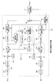
図1は、本技術に係る実施の形態としての記録装置1の全体的な内部構成を示したブロック図である。
先ず図1には、円盤状の光記録媒体である光ディスクDが示されている。なお、光記録媒体とは、光の照射により信号の記録又は再生が行われる記録媒体を総称したものである。
<1. First Embodiment>
[1-1. Overall configuration of recording apparatus]
FIG. 1 is a block diagram showing an overall internal configuration of a recording apparatus 1 as an embodiment according to the present technology.
First, FIG. 1 shows an optical disc D which is a disc-shaped optical recording medium. The optical recording medium is a generic term for recording media on which signals are recorded or reproduced by light irradiation.
ここで、光ディスクDは、その記録層LWに光照射に応じた信号記録が可能な記録可能型の光ディスクであるとする。
また本例の場合、光ディスクDは、記録層LWの少なくとも一部に案内溝が形成されていない領域が設けられ、記録装置1は、そのような案内溝の非形成領域に対して記録を行うことが前提とされているとする。
Here, it is assumed that the optical disc D is a recordable optical disc capable of recording signals on the recording layer LW according to light irradiation.
In the case of this example, the optical disc D is provided with a region where no guide groove is formed in at least a part of the recording layer LW, and the recording apparatus 1 performs recording in such a region where the guide groove is not formed. It is assumed that.
記録装置1に装填された光ディスクDは、記録装置1の所定位置に設けられたターンテーブルに積載され、図中のスピンドルモータ(SPM)2により例えば一定線速度(CLV)など所定の回転制御方式により回転駆動される。 The optical disk D loaded in the recording apparatus 1 is loaded on a turntable provided at a predetermined position of the recording apparatus 1, and a predetermined rotation control method such as a constant linear velocity (CLV) is performed by a spindle motor (SPM) 2 in the figure. It is rotationally driven by.
このように回転駆動される光ディスクDに光照射を行うための構成として、図中の光ピックアップOPが設けられる。 The optical pickup OP in the figure is provided as a configuration for irradiating light to the optical disk D that is rotationally driven in this way.
ここで、図2に光ピックアップOPの内部構成を示す。
図2に示されるように光ピックアップOP内には、記録用レーザ15-1、ATS(Adjacent Track Servo:隣接トラックサーボ)用レーザ15-2が設けられる。
本実施の形態では、光ディスクDに対してATSによる記録を行うものとされており、記録用レーザ15-1は先の図7に示した記録用スポットSwrを形成するための記録用レーザ光の光源となり、ATS用レーザ15-2はATS用スポットSatsを形成するためのATS用レーザ光の光源となる。
記録用レーザ15-1は後述する駆動信号D-wrにより記録信号に応じた発光駆動が為され、ATS用レーザ15-2は後述する駆動信号D-srにより再生パワーによる連続発光動作が得られるように発光駆動される。
なお、先の図7の説明から理解されるように、ATSにおいては記録用スポットSwrが先行スポット、ATS用スポットSatsが後行スポットとなり、これらスポットS間の間隔(半径方向における間隔)は、記録層LWに設定されたトラックピッチに等しいものとする。この場合の光学系は、このようなスポット位置関係が実現されるように構成されている。
Here, FIG. 2 shows an internal configuration of the optical pickup OP.
As shown in FIG. 2, a recording laser 15-1 and an ATS (Adjacent Track Servo) laser 15-2 are provided in the optical pickup OP.
In this embodiment, the optical disc D is recorded by ATS, and the recording laser 15-1 uses the recording laser beam for forming the recording spot Swr shown in FIG. The ATS laser 15-2 serves as a light source, and serves as an ATS laser light source for forming the ATS spot Sats.
The recording laser 15-1 is driven to emit light in accordance with the recording signal by a driving signal D-wr, which will be described later, and the ATS laser 15-2 can obtain a continuous light emission operation by reproducing power by a driving signal D-sr, which will be described later. In this way, light emission is driven.
As can be understood from the description of FIG. 7, in the ATS, the recording spot Swr is a preceding spot and the ATS spot Sats is a trailing spot, and an interval between these spots S (an interval in the radial direction) is: It is assumed that it is equal to the track pitch set in the recording layer LW. The optical system in this case is configured to realize such a spot position relationship.
記録用レーザ15-1より発せられた記録用レーザ光、及びATS用レーザ15-2より発せられたATS用レーザ光は、コリメータレンズ16を介して平行光となるようにされた後、PBS(偏光ビームスプリッタ)17に入射する。
PBS17は、このように光源側から入射した記録用レーザ光及びATS用レーザ光を透過するように構成される。
The recording laser light emitted from the recording laser 15-1 and the ATS laser light emitted from the ATS laser 15-2 are converted into parallel light via the
The
PBS17を透過した記録用レーザ光及びATS用レーザ光は1/4波長板18を介した後、レンズアクチュエータ20により保持された対物レンズ19を介して光ディスクDの記録層LWに集光する。
The recording laser light and the ATS laser light transmitted through the
レンズアクチュエータ20は、対物レンズ19を光ディスクDに接離する方向(フォーカス方向)及び光ディスクDの半径方向に平行な方向(フォーカス方向に直交する方向:トラッキング方向)に変位可能に保持する。
レンズアクチュエータ20には、フォーカスコイル、トラッキングコイルが備えられ、それぞれに駆動信号(後述するドライブ信号FD、TD)が与えられることで、対物レンズ19をフォーカス方向、トラッキング方向にそれぞれ変位させる。
The
The
ここで、上記のように記録層LWに対してATS用レーザ光が照射されることに応じては、該記録層LWからのATS用レーザ光の反射光が得られる。
このように得られたATS用レーザ光の反射光は、対物レンズ19を介した後、1/4波長板18を介してPBS17に入射する。
Here, when the recording layer LW is irradiated with the ATS laser light as described above, the reflected light of the ATS laser light from the recording layer LW is obtained.
The reflected light of the ATS laser light obtained in this way passes through the objective lens 19 and then enters the
このようにPBS17に入射するATS用レーザ光の反射光は、往路と復路とで1/4波長板18を2回通過することで、往路光との比較でその偏光方向が90度回転していることになる。この結果、上記のように入射したATS用レーザ光の反射光は、PBS17にて反射される。
As described above, the reflected light of the ATS laser light incident on the
PBS17にて反射されたATS用レーザ光の反射光は、集光レンズ21を介して受光部22の受光面上に集光する。
ここで、受光部22がATS用レーザ光の反射光を受光して得られる受光信号のことを、以下、受光信号DTと表記する。
本例における受光部22は、複数の受光素子を有し、それらがATS用レーザ光の反射光を受光することで複数の受光信号が得られる。上記受光信号DTは、これら複数の受光素子による受光信号を包括して表している。
The reflected light of the ATS laser light reflected by the
Here, the light receiving signal obtained by the light receiving unit 22 receiving the reflected light of the ATS laser light is hereinafter referred to as a light receiving signal DT.
The light receiving unit 22 in this example has a plurality of light receiving elements, and a plurality of light receiving signals are obtained by receiving the reflected light of the ATS laser light. The light reception signal DT comprehensively represents light reception signals from the plurality of light receiving elements.
説明を図1に戻す。
記録装置1には、光ピックアップOP内に設けられた記録用レーザ15-1、ATS用レーザ15-2をそれぞれ発光駆動するための構成として、レーザドライバ3、レーザドライバ4が設けられる。
レーザドライバ4は、後述するコントローラ13からの指示に基づき、ATS用レーザ15-2を再生パワーにより連続発光駆動するための駆動信号D-srを生成し、該駆動信号D-srによりATS用レーザ15-2を発光駆動する。
Returning to FIG.
The recording apparatus 1 is provided with a laser driver 3 and a laser driver 4 as a configuration for driving the recording laser 15-1 and the ATS laser 15-2 provided in the optical pickup OP, respectively.
The laser driver 4 generates a drive signal D-sr for continuously driving the ATS laser 15-2 with the reproduction power based on an instruction from the
また、レーザドライバ3は、記録データに基づく発光動作をさせるための駆動信号D-wrを生成する。
ここで、図中の記録変調部6は、記録データを入力し、該記録データに対してエラー訂正符号の付加や所定の記録変調符号化処理を施すなどして、記録層LWに実際に記録されるべき「0」「1」の2値データ列である記録変調符号列を得る。
記録変調部6で得られた2値データ列(記録変調符号列)はライトストラテジ回路7に入力される。
また本例の場合、上記記録変調符号列は後述する復調部12におけるベリファイ部12aに対しても供給される。
Further, the laser driver 3 generates a drive signal D-wr for performing a light emission operation based on the recording data.
Here, the recording modulation unit 6 in the figure inputs the recording data, and actually records the recording data on the recording layer LW by adding an error correction code to the recording data or performing a predetermined recording modulation encoding process. A recording modulation code string which is a binary data string of “0” and “1” to be performed is obtained.
The binary data string (recording modulation code string) obtained by the recording modulation unit 6 is input to the write strategy circuit 7.
In the case of this example, the recording modulation code string is also supplied to a verify
ライトストラテジ回路7は、コントローラ13からの指示に応じて、上記記録変調符号列に基づく記録パルスを生成し、その結果を記録信号Wrpとして出力する。
記録信号Wrpはレーザドライバ3に供給される。
なお、本例の場合、記録信号Wrpはクロストークキャンセル部10にも供給されるがこれについては後述する。
The write strategy circuit 7 generates a recording pulse based on the recording modulation code string in response to an instruction from the
The recording signal Wrp is supplied to the laser driver 3.
In this example, the recording signal Wrp is also supplied to the
レーザドライバ3は、ライトストラテジ回路7より入力される記録信号Wrpに基づく駆動信号D-wrを生成し、該駆動信号D-wrに基づき記録用レーザ15-1を発光駆動する。これにより記録層LWに対し記録データに応じたマーク列が記録される。 The laser driver 3 generates a drive signal D-wr based on the recording signal Wrp input from the write strategy circuit 7, and drives the recording laser 15-1 to emit light based on the drive signal D-wr. As a result, a mark row corresponding to the recording data is recorded on the recording layer LW.
光ピックアップOPで得られた受光信号DTは、マトリクス回路5に供給される。
マトリクス回路5は、図2に示した受光部22としての複数の受光素子からの受光信号DT(出力電流)に基づき、RF信号(再生信号)、フォーカスエラー信号FE、トラッキングエラー信号TEを生成する。
フォーカスエラー信号FEは、記録層LWに対するATS用レーザ光のフォーカス誤差を表す信号となる。またトラッキングエラー信号TEは、記録層LWに形成されたトラック(マーク列)に対するATS用レーザ光のスポット位置の半径方向における位置誤差を表す信号となる。
マトリクス回路5で得られたRF信号はクロストークキャンセル部10に、またフォーカスエラー信号FE、トラッキングエラー信号TEはサーボ回路8にそれぞれ供給される。
The light reception signal DT obtained by the optical pickup OP is supplied to the
The
The focus error signal FE is a signal representing the focus error of the ATS laser light with respect to the recording layer LW. The tracking error signal TE is a signal representing a position error in the radial direction of the spot position of the ATS laser beam with respect to the track (mark row) formed in the recording layer LW.
The RF signal obtained by the
サーボ回路8は、フォーカスエラー信号FE、トラッキングエラー信号TEに対するサーボ演算処理を行ってフォーカスサーボ信号FS、トラッキングサーボ信号TSをそれぞれ生成する。
The
アクチュエータドライバ9は、サーボ回路8で生成されたフォーカスサーボ信号FS、トラッキングサーボ信号TSに基づくフォーカスドライブ信号FD、トラッキングドライブ信号TDを生成し、これらフォーカスドライブ信号FD、トラッキングドライブ信号TDによりレンズアクチュエータ20のフォーカスコイル、トラッキングコイルをそれぞれ駆動する。
これにより、対物レンズ19についてのフォーカスサーボ制御(ATS用スポットSats及び記録用スポットSwrを記録対象の記録層LWに合焦させるサーボ制御)、トラッキングサーボ制御(ATS用スポットSatsを記録対象の記録層LW上のトラックに追従させるサーボ制御)が実現される。
The actuator driver 9 generates a focus drive signal FD and a tracking drive signal TD based on the focus servo signal FS and the tracking servo signal TS generated by the
Thereby, the focus servo control (servo control for focusing the ATS spot Sats and the recording spot Swr on the recording layer LW) for the objective lens 19 and the tracking servo control (the ATS spot Sats for the recording layer to be recorded). Servo control to follow the track on the LW) is realized.
なお、サーボ回路8は、コントローラ13からの指示に応じ、トラッキングサーボをオフとして所要のジャンプパルスを出力することで、いわゆるトラックジャンプ動作を実現することが可能に構成されている。
また、図示は省略したが、記録装置1には、実際には光ピックアップOP全体をディスク半径方向に平行な方向にスライド移動するためのスライド駆動部が設けられ、サーボ回路8は、コントローラ13からの指示に応じて該スライド駆動部を駆動制御することで、光ピックアップOP全体をスライド移動させる。
The
Although not shown, the recording apparatus 1 is actually provided with a slide driving unit for sliding the entire optical pickup OP in a direction parallel to the disk radial direction. The entire optical pickup OP is slid and moved by controlling the slide drive unit according to the instruction.
マトリクス回路5で得られたRF信号はクロストークキャンセル部10を介してビタビ復号器11に入力される。
ここで本例の場合、RF信号の2値化方式としてPRML(Partial Response Maximum Likelihood)復号方式が採用される。
クロストークキャンセル部10内には、採用されるPRのクラス(例えばPR(1,2,2,2,1)など)に応じたPR等化処理をRF信号に対して施すための等化フィルタが設けられる(後述するイコライザ40)。このようなPR等化処理が施されたRF信号が、ビタビ復号器11に入力される。
クロストークキャンセル部10は、本例のようにATSを採用する場合においてRF信号に重畳するものとされる、記録用スポットSwrのライト発光に応じた迷光信号成分(クロストーク成分)をキャンセルするための処理を行うように構成されるが、これについては後に改めて説明する。
The RF signal obtained by the
In this example, a PRML (Partial Response Maximum Likelihood) decoding method is adopted as the binarization method of the RF signal.
In the
The
ビタビ復号器11は、上記のようにPR等化処理の施されたRF信号に基づき最尤復号処理を行い、上述した記録変調符号列を再生した2値データ列DDを得る。
該2値データ列DDは、復調部12に供給される。
なお、本例の場合、ビタビ復号器11による上記最尤復号処理の過程で得られる最尤パスの情報が、クロストークキャンセル部10に対して供給されるが、これについては後述する。
The
The binary data string DD is supplied to the
In this example, the maximum likelihood path information obtained in the course of the maximum likelihood decoding process by the
復調部12は、2値データ列DDに対する記録変調符号の復号化やエラー訂正処理等の所定の復調処理を施すことで、前述の記録データを復元(再生)した再生データを得る。
また本例の場合、復調部12内にはベリファイ部12aが設けられる。ベリファイ部12aは、2値データ列DDと記録変調部6からの記録変調符号とに基づきベリファイ処理を行う。ベリファイ部12aによるベリファイ結果は、コントローラ13に供給される。
The
In the case of this example, a verify
コントローラ13は、例えばCPU(Central Processing Unit)やROM(Read Only Memory)、RAM(Random Access Memory)などのメモリ(記憶装置)を備えたマイクロコンピュータで構成され、例えば上記ROM等に記憶されたプログラムに従った制御・処理を実行することで、記録装置1の全体制御を行う。
例えばコントローラ13は、サーボ回路8に対する指示を行って、ATS用スポットSatsの位置を記録層LW上の所要位置に移動させるシーク動作制御を行う。
またコントローラ13は、レーザドライバ4に対する指示を行ってATS用レーザ15-2を再生パワーで連続発光させる。
The
For example, the
Further, the
なお、ATSによる記録を開始するためには、ATS用スポットSatsがトラッキングサーボをかける対象となる既記録トラック(ATSのためのガイド用トラック)が形成されている必要がある。
このようなガイド用トラックについては、例えばディスク最内周部などに予め形成しておく(つまりこのようなガイド用トラックが予め形成されている光ディスク製品とする)ことが考えられる。すなわちその場合、記録装置1は、このように予め形成されたガイド用トラックの終端の1周以上手前となる部分に対しATS用スポットSatsによるトラッキングサーボをかけ、その後、ATS用スポットSatsが上記ガイド用トラックの終端の1周手前位置に至ったことに応じて記録用スポットSwrによる記録を開始することで、ATSによる記録を開始することができる。
或いは、ガイド用トラックは記録装置1が自ら形成することも可能である。つまりその場合、記録装置1は、記録を開始するとしたとき、対物レンズ19を記録進行方向側(例えば内周→外周に記録進行する場合は外周側)に移動させながら記録用スポットSwrによりガイド用トラックを少なくとも1周以上形成する。その後、このように形成したガイド用トラックの終端の1周以上手前となる部分に対しATS用スポットSatsによるトラッキングサーボをかけ、ATS用スポットSatsがガイド用トラックの終端の1周手前位置に至ったことに応じて記録用スポットSwrによる記録を開始する。これによりATSによる記録を開始することができる。
これらの制御は、コントローラ13がサーボ回路8に対する指示を行うことで実現できる。
In order to start recording by ATS, it is necessary to form an already recorded track (guide track for ATS) on which ATS spot Sats is to be subjected to tracking servo.
Such a guide track may be formed in advance, for example, on the innermost periphery of the disc (that is, an optical disc product in which such a guide track is formed in advance). That is, in this case, the recording apparatus 1 applies the tracking servo by the ATS spot Sats to a portion that is one or more rounds before the end of the guide track formed in advance as described above, and the ATS spot Sats is then applied to the guide track. The recording by the ATS can be started by starting the recording by the recording spot Swr in response to reaching the position one round before the end of the recording track.
Alternatively, the recording apparatus 1 can form the guide track itself. That is, in this case, when the recording apparatus 1 starts recording, the recording device 1 moves the objective lens 19 in the recording progress direction side (for example, the outer periphery side when recording progresses from the inner periphery to the outer periphery), and guides the recording lens 1 by the recording spot Swr. At least one track is formed. After that, the tracking servo by the ATS spot Sats is applied to the portion that is one or more laps before the end of the guide track thus formed, and the ATS spot Sats reaches the position one lap before the end of the guide track. Accordingly, recording by the recording spot Swr is started. Thereby, recording by ATS can be started.
These controls can be realized by the
[1-2.クロストークキャンセル部の内部構成]
図3は、図1に示したクロストークキャンセル部10の内部構成を示したブロック図である。
なお、この図3ではクロストークキャンセル部10の内部構成と共に、図1に示したビタビ復号器11も併せて示している。
[1-2. Internal configuration of the crosstalk cancellation unit]
FIG. 3 is a block diagram showing an internal configuration of the
FIG. 3 also shows the
クロストークキャンセル部10において、図1に示したマトリクス回路5からのRF信号は、A/D変換器29でデジタルサンプリングされ、DCカット部30でDC成分が除去された後、乗算器31に入力される。
乗算器31に入力されたRF信号は、図中のAGC(Auto Gain Control)回路32によってそのゲインが制御される。なお、AGC回路32は、後述する位相誤差検出部35の出力に基づきゲイン制御を行う。
乗算器31を介したRF信号は、インターポレータ33に入力される。
In the
The gain of the RF signal input to the
The RF signal that has passed through the
ここで、本例では、RF信号についてチャンネルクロックとのタイミング同期を行うためのPLL(Phase Locked Loop)回路として、上記インターポレータ33を備えたITR(Interpolated Timing Recovery)方式によるPLL回路38を設けるものとしている。
なお便宜上、当該ITR方式によるPLL回路38についての説明は後に改めて行う。
Here, in this example, a PLL circuit 38 based on an ITR (Interpolated Timing Recovery) system including the
For convenience, the ITR PLL circuit 38 will be described later.
インターポレータ33を介したRF信号は、後述するPLL回路38による作用によりチャネルクロックとのタイミング同期が図られ、図中のプリイコライザ(preEQ)39に入力される。
このプリイコライザ39は例えばFIR(Finite Impulse Response)フィルタで構成され、RF信号に対して高域強調型の等化処理(例えば2T、3T信号をブースト)を施す。
The RF signal that has passed through the
The pre-equalizer 39 is composed of, for example, a FIR (Finite Impulse Response) filter, and performs high-frequency emphasis equalization processing (for example, boosting 2T and 3T signals) on the RF signal.
プリイコライザ39による等化処理(ブースト処理)の施されたRF信号は、PR等化器としてのイコライザ40に入力される。
ここで、本例の場合、イコライザ40は適応等化型のFIRフィルタで構成され、ビタビ復号器11による復号結果に応じた適応型PR等化処理を行う。
具体的に、ビタビ復号器11で得られる最尤パスの情報が、クロストークキャンセル部10内に設けられた目標信号生成部41に入力される。この目標信号生成部41は、上記最尤パスに対し、採用されるPRのクラス(例えば本例の場合はPR(1,2,2,2,1))で想定される符号間干渉を付与するための重み付け加算処理を施し、等化目標信号を生成する。具体的には、最尤パスに対して上記PR(1,2,2,2,1)などのPR特性係数に従った重み付け加算処理を施して、上記符号間干渉を付与する。そしてその結果を、イコライザ40に出力する。
イコライザ40は、目標信号生成部41が最尤パスに基づき生成した等化目標信号を入力し、該目標信号に基づいて等化誤差を算出する。そして、該等化誤差に基づき、例えばLMS(Least Mean Square)アルゴリズムによりタップ係数の更新を行って、RF信号に対し適応型のPR等化処理を施す。
The RF signal subjected to equalization processing (boost processing) by the pre-equalizer 39 is input to the
Here, in the case of this example, the
Specifically, the maximum likelihood path information obtained by the
The
イコライザ40にてPR等化処理の施されたRF信号は、図中の減算器42で後述する適応型FIRフィルタ49の出力信号との減算が行われた後、ビタビ復号器11に入力される。
The RF signal that has been subjected to PR equalization processing by the
ここで、ITR方式によるPLL回路38について説明する。
周知のようにITR方式は、インターポレータによってRF信号の波形補間を行うことで、本来のサンプリングタイミングにおけるサンプリング値が得られるようにタイミング同期を図る方式となる。
Here, the PLL circuit 38 by the ITR method will be described.
As is well known, the ITR method is a method of synchronizing the timing so that the sampling value at the original sampling timing is obtained by performing waveform interpolation of the RF signal by an interpolator.
図のようにこの場合のPLL回路38は、インターポレータ33、プリイコライザ34、位相誤差検出部35、LPF(ローパスフィルタ)36、及びNCO(Number Control Oscillator)37を備えて構成される。
インターポレータ33を介したRF信号は、プリイコライザ34を介して位相誤差検出部35に入力される。
なお、プリイコライザ34は先のプリイコライザ39と同様、RF信号に対して高域強調型の等化処理(高域ブースト処理)を施すものであり、例えばFIRフィルタで構成される。
As shown in the figure, the PLL circuit 38 in this case includes an
The RF signal via the
Note that the pre-equalizer 34 performs high-frequency emphasis equalization processing (high-frequency boost processing) on the RF signal, similarly to the
位相誤差検出部35は、プリイコライザ34を介したRF信号に基づき、現位相と所定の目標位相(本来のサンプリングタイミング)との位相誤差を計算により求める。
そして、位相誤差検出部35にて得られた位相誤差信号は、ループフィルタとしてのLPF36に入力されてその低域成分が抽出される。これにより、本来のサンプリングタイミングが得られるように補正するための周波数制御信号(位相制御信号)が得られる。
The phase
Then, the phase error signal obtained by the
LPF36で計算された位相制御信号は、NCO37に入力される。NCO37は、入力される位相制御信号に基づき、自らが出力するクロック信号の位相を変化させる。
The phase control signal calculated by the
インターポレータ33は、NCO37から入力されるクロック信号に基づき、RF信号についての波形補間処理を行う。これにより、本来のサンプリングタイミングにおけるRF信号サンプリング値が得られるように、タイミング同期が図られる。
The
なお、ITR方式によりタイミング同期が図られる原理については例えば下記参考文献1等に記載されている。
参考文献1・・・特開2005−108295号公報
Note that the principle of timing synchronization by the ITR method is described in, for example, Reference Document 1 below.
Reference 1 ... JP 2005-108295 A
クロストークキャンセル部10には、上記により説明したRF信号についてのPR等化及びタイミング同期のための構成と共に、RF信号に重畳するものとされる迷光信号成分を、記録信号Wrpに基づきキャンセルするための構成が設けられる。
具体的には、図中のLPF43、DCカット部44、乗算器45、GCA(Gain Control Amp)46、インターポレータ47、プリイコライザ48、適応等FIRフィルタ49、及び減算器42が設けられている。
The
Specifically, an
図示するように記録信号Wrpは、LPF43に入力される。なお本例の場合、ライトストラテジ回路7から出力される記録信号Wrpはデジタル信号であるとする。
As shown in the figure, the recording signal Wrp is input to the
LPF43は、記録信号Wrpの低域成分を抽出(中・高域成分を通過)する。
図4は、LPF43による作用を説明するための図であり、具体的には、LPF43に入力前の記録信号Wrpの波形(図中、Wrp)とLPF43より出力される記録信号Wrp(図中LPF出力)とを対比して示している。
この図に示されるようにLPF43を介することで、記録パルスとしての記録信号Wrpが平滑化され、RF信号側に重畳する迷光信号成分を疑似的に再現することができる。
なお、この点からも理解されるように、LPF43のカットオフ周波数は、記録パルスとしての信号Wrpから、RF信号側に重畳する迷光信号成分を適正に再現できるようにして設定されるべきものとなる。
The
FIG. 4 is a diagram for explaining the action of the
As shown in this figure, through the
As understood from this point, the cutoff frequency of the
図3において、LPF43を介した記録信号Wrpを、図のように信号Scと表記する。
信号Scは、DCカット部44によりDC成分が除去された後、乗算器45に入力される。乗算器45に入力された信号Scは、GCA46によってそのゲインが制御される。
In FIG. 3, the recording signal Wrp via the
The signal Sc is input to the
乗算器45を介した信号Scは、インターポレータ47に入力される。
このインターポレータ47は、前述したNCO37からの位相制御信号に基づき、信号Scの波形補間処理を行う。これにより信号Scについて、RF信号側とのタイミング同期が図られる。
The signal Sc that has passed through the
The
インターポレータ47を介した信号Scは、プリイコライザ48による等化処理が施された後、適応型FIRフィルタ49に入力される。
The signal Sc passed through the
ここで、プリイコライザ48は、PR信号に対しプリイコライザ39によるブースト処理が施されることに対応させて、信号Scにも同様のブースト処理を施すために設けられたものである。すなわちプリイコライザ48は、信号Scに対して先のプリイコライザ39と同様の高域強調型の等化処理を施す。
このプリイコライザ48としても例えばFIRフィルタで構成される。
Here, the pre-equalizer 48 is provided to perform the same boost process on the signal Sc in association with the boost process performed by the pre-equalizer 39 on the PR signal. That is, the pre-equalizer 48 performs high-frequency emphasis equalization processing similar to that of the pre-equalizer 39 on the signal Sc.
The pre-equalizer 48 is also composed of, for example, an FIR filter.
また、適応型FIRフィルタ49は、RF信号に対してイコライザ40による適応型のPR等化処理が施されることに対応させて、信号Scにも同様の適応型PR等化処理を施すために設けられたものである。
図示するように適応型FIRフィルタ49には、前述した目標信号生成部41が最尤パス信号に基づいて生成した等化目標信号が入力される。適応型FIRフィルタ49は、該目標信号に基づくタップ係数更新処理を行って信号Scに対し先のイコライザ40と同様の適応型PR等化処理を施す。なお、この場合もタップ係数の更新はLMSアルゴリズムにより行う。
Further, the
As shown in the figure, the equalization target signal generated by the target
適応型FIRフィルタ49によるPR等化処理が施された信号Scは、減算器42に入力される。
減算器42は、イコライザ40から入力されるPR等化後のRF信号から、適応型FIRフィルタ49によるPR等化後の信号Scを減算する。
これにより、RF信号に重畳するものとされる、記録用スポットSwrのライト発光に応じた迷光信号成分の除去が図られる。
このように迷光信号成分が除去されたRF信号が、ビタビ復号器11に入力されることとなる。
The signal Sc that has been subjected to PR equalization processing by the
The
As a result, the stray light signal component corresponding to the light emission of the recording spot Swr, which is to be superimposed on the RF signal, can be removed.
Thus, the RF signal from which the stray light signal component is removed is input to the
上記のように本実施の形態では、ATSが採用されて、記録光としての第1の光と該第1の光とは異なる第2の光とを照射し、上記第2の光の受光の際に上記第1の光の発光に伴う迷光が漏れ込むことにより上記第2の光の再生信号に迷光信号成分が重畳してしまう場合において、該迷光信号成分の除去を図ることができる。
これによれば、例えば本実施の形態のように上記第2の光の再生信号に基づき記録光による記録信号のベリファイを行う場合において、その精度の向上を図ることができる。
As described above, in the present embodiment, the ATS is employed, and the first light as the recording light and the second light different from the first light are irradiated, and the second light is received. In the case where the stray light signal component is superimposed on the reproduction signal of the second light due to leakage of the stray light accompanying the emission of the first light, the stray light signal component can be removed.
According to this, for example, in the case where the recording signal is verified by the recording light based on the reproduction signal of the second light as in the present embodiment, the accuracy can be improved.
<2.第2の実施の形態>
ここで、第1の実施の形態では、迷光信号成分のキャンセルをビタビ復号器11に供給されるRF信号に対してのみ行うものとしたが、第2の実施の形態は、迷光信号成分のキャンセルをPLL回路に入力されるRF信号に対しても行うものである。
<2. Second Embodiment>
Here, in the first embodiment, the stray light signal component is canceled only for the RF signal supplied to the
図5は、第2の実施の形態の記録装置が備えるクロストークキャンセル部10’の内部構成を示したブロック図である。
なお、記録装置全体の構成については、先の第1の実施の形態の場合と同様となるため改めての図示による説明は省略する。
また以下の説明において、既にこれまでで説明済みとなった部分と同様となる部分については同一符号を付して説明を省略する。
FIG. 5 is a block diagram illustrating an internal configuration of the
Note that the configuration of the entire recording apparatus is the same as in the case of the first embodiment, and a description thereof by way of illustration is omitted.
Moreover, in the following description, the same code | symbol is attached | subjected about the part similar to the part already demonstrated so far, and description is abbreviate | omitted.
図5において、第2の実施の形態のクロストークキャンセル部10’は、第1の実施の形態のクロストークキャンセル部10との比較で、適応型FIRフィルタ51が追加されると共に、PLL回路38に代えてPLL回路38’が設けられた点が異なる。
PLL回路38’は、PLL回路38に対して減算器52が追加されたものとなる。
In FIG. 5, the
The PLL circuit 38 ′ is obtained by adding a
図示するように適応型FIRフィルタ51には、インターポレータ47からプリイコライザ48に対して出力される信号Scが分岐して入力される。
適応型FIRフィルタ51には、目標信号生成部41が最尤パス信号に基づいて生成した等化目標信号が入力される。適応型FIRフィルタ51は、該目標信号に基づくタップ係数更新処理を行って信号Scに対し適応型の等化処理を施す。なお、この場合もタップ係数の更新はLMSアルゴリズムにより行う。
As shown in the figure, the signal Sc output from the
The equalization target signal generated by the target
適応型FIRフィルタ51により等化処理が施された信号Scは、PLL回路38’に設けられた減算器52に入力される。
図示するように減算器52には、上記適応型FIRフィルタ51により等化処理が施された信号Scと共に、プリイコライザ34によるブースト処理が施されたRF信号が入力される。
減算器52は、プリイコライザ34によるブースト処理後のRF信号から適応型FIRフィルタ51による等化処理後の信号Scを減算する。
これにより、PLL回路に入力される上記RF信号についても、これに重畳する迷光信号成分の除去が図られる。
このように迷光信号成分が除去されたRF信号が、図のように位相誤差検出部35に入力される。
The signal Sc that has been equalized by the
As shown in the figure, the
The
Thus, the stray light signal component superimposed on the RF signal input to the PLL circuit can be removed.
The RF signal from which the stray light signal component has been removed is input to the
上記のようにしてPLL回路に入力されるRF信号についても迷光信号成分のキャンセル処理を施すことで、RF信号、及び信号Scについてより正確なタイミング同期が図られ、さらなる再生性能の向上が図られる。
By performing the stray light signal component cancellation process on the RF signal input to the PLL circuit as described above, more accurate timing synchronization can be achieved for the RF signal and the signal Sc, thereby further improving the reproduction performance. .
<3.実験結果>
図6は、実施の形態の迷光信号成分キャンセル手法の有効性を実証するための実験結果を示している。
具体的に図6では、ライト発光強度(W)をそれぞれFull(例えば3mW)とした場合、その2/3とした場合(W:2/3)、1/3とした場合(W:1/3)に得られるiMLSEの測定結果を棒グラフにより表している。図中の黒塗りで示すグラフが迷光信号成分のキャンセル無しの場合、白抜きで示すグラフが迷光信号成分のキャンセル有りの場合(つまり実施の形態の場合)の測定結果をそれぞれ表す。
なお、この図6では、迷光信号成分のキャンセル手法として第2の実施の形態で説明したキャンセル手法を採用した場合における結果を示している。
<3. Experimental results>
FIG. 6 shows experimental results for demonstrating the effectiveness of the stray light signal component cancellation method of the embodiment.
Specifically, in FIG. 6, when the light emission intensity (W) is set to Full (for example, 3 mW), 2/3 (W: 2/3), 1/3 (W: 1 / W). The iMLSE measurement results obtained in 3) are represented by bar graphs. In the figure, black graphs show measurement results when stray light signal components are not canceled, and white graphs show measurement results when stray light signal components are canceled (that is, in the embodiment).
FIG. 6 shows the result when the canceling method described in the second embodiment is adopted as the stray light signal component canceling method.
この図6を参照して明らかなように、実施の形態の迷光信号成分キャンセル手法によれば、ライト発光強度(W)がFull、2/3、1/3のそれぞれにおいて、迷光キャンセルを行わない場合との比較でiMLSEの改善が図られ、再生性能が向上することが分かる。
As apparent from FIG. 6, according to the stray light signal component cancellation method of the embodiment, stray light cancellation is not performed when the light emission intensity (W) is full, 2/3, or 1/3, respectively. It can be seen that iMLSE is improved compared to the case, and the reproduction performance is improved.
<4.変形例>
以上、本技術に係る実施の形態について説明したが、本技術はこれまでで説明した具体例に限定されるべきものではない。
例えばこれまでの説明では、本技術がATSによる記録(及びベリファイ)を行う場合に適用される場合を例示したが、本技術は、ATSが採用される場合以外にも、記録光としての第1の光と該第1の光とは異なる第2の光とを照射し、上記第2の光の受光の際に上記第1の光の発光に伴う迷光が漏れ込むことにより上記第2の光の再生信号に迷光信号成分が重畳する場合に広く好適に適用可能なものである。
<4. Modification>
As mentioned above, although embodiment which concerns on this technique was described, this technique should not be limited to the specific example demonstrated so far.
For example, in the description so far, the case where the present technology is applied when recording (and verifying) by ATS is exemplified, but the present technology is not limited to the case where ATS is employed, but the first technology as the recording light is used. And the second light different from the first light, and the stray light accompanying the emission of the first light leaks when the second light is received. This is widely applicable when stray light signal components are superimposed on the reproduction signal.
また、これまでの説明では、ライトストラテジ回路7が出力する記録信号Wrp(記録パルス)を入力して迷光信号成分の除去を図るものとしたが、迷光信号成分を除去するための迷光キャンセル信号は、記録データに基づき生成すればよく、必ずしも記録信号Wrpに基づき生成する必要性はない。 In the above description, the recording signal Wrp (recording pulse) output from the write strategy circuit 7 is input to remove the stray light signal component. However, the stray light cancellation signal for removing the stray light signal component is It suffices to generate it based on the recording data, and it is not always necessary to generate it based on the recording signal Wrp.
またこれまでの説明では、RF信号側、信号Sc側にそれぞれPR等化処理を施すための等化フィルタを、適応型の等化フィルタ(イコライザ40、適応型FIRフィルタ49)とする場合を例示したが、これらPR等化のための等化フィルタについては、必ずしも適応型の等化フィルタを用いる必要性はない。
また、第2の実施の形態のようにPLL回路に入力されるRF信号に対して迷光信号成分のキャンセル処理を施す場合も同様に、信号Scに対し等化処理を施すための等化フィルタとしては、適応型FIRフィルタ51を用いる必要性はなく、非適応型の等化フィルタを用いることもできる。
但し、実施の形態で例示したように最尤パスに基づく適応等化処理を施すものとした方が、再生性能の向上を図る上では望ましいものとなる。
In the description so far, the case where the equalization filters (
Similarly, in the case where the stray light signal component canceling process is performed on the RF signal input to the PLL circuit as in the second embodiment, as an equalizing filter for performing the equalizing process on the signal Sc. There is no need to use the
However, it is desirable to perform adaptive equalization processing based on the maximum likelihood path as exemplified in the embodiment in order to improve reproduction performance.
また、これまでの説明では、RF信号の2値データ列DDを得るための方式としてPRML方式を採用する場合を例示したが、本技術はPRML方式が採用される場合以外にも広く好適に適用できるものである。 In the above description, the case where the PRML method is adopted as a method for obtaining the binary data string DD of the RF signal has been exemplified. However, the present technology is widely and suitably applied to cases other than the case where the PRML method is adopted. It can be done.
また、RF信号のタイミング同期の方式としてもITR方式に限定されるものではなく、本技術はITR方式以外のタイミング同期方式が採用される場合にも広く好適に適用可能なものである。 Further, the timing synchronization method of the RF signal is not limited to the ITR method, and the present technology can be widely and suitably applied when a timing synchronization method other than the ITR method is adopted.
また、本技術は以下に示す構成を採ることもできる。
(1)
記録光としての第1の光と、該第1の光とは異なる第2の光とを光記録媒体に照射すると共に、上記第2の光の上記光記録媒体からの戻り光を受光する光照射/受光部と、
記録データに基づき、上記第1の光の光源を発光駆動することで上記光記録媒体に対する記録を行う記録部と、
上記第2の光についての受光信号に基づき上記光記録媒体に記録された信号についての再生信号を得る再生信号生成部と、
記録データに基づき、上記第2の光の受光の際に上記第1の光の発光に伴う迷光が漏れ込むことにより上記再生信号に重畳する迷光信号成分をキャンセルするための迷光キャンセル信号を生成し、該迷光キャンセル信号により上記再生信号に重畳する上記迷光信号成分をキャンセルする迷光信号成分キャンセル部と
を備える記録装置。
(2)
上記迷光信号成分キャンセル部は、
上記記録部で得られる、上記記録光の光源を発光駆動するための記録パルス信号に基づいて上記迷光キャンセル信号を生成する
上記(1)に記載の記録装置。
(3)
上記迷光信号成分キャンセル部は、
記録パルス信号を平滑化して上記迷光キャンセル信号を生成する
上記(2)に記載の記録装置。
(4)
上記再生信号についてチャンネルクロックとのタイミング同期を行うためのPLL(Phase Locked Loop)回路を備え、
該PLL回路が、上記迷光キャンセル信号により上記迷光信号成分がキャンセルされた信号に基づきPLL処理を行うように構成される
上記(1)乃至(3)何れかに記載の記録装置。
(5)
上記光照射/受光部は、
上記第1の光と上記第2の光とを共通の対物レンズを介して上記光記録媒体に照射する
上記(1)乃至(4)何れかに記載の記録装置。
(6)
上記第2の光の受光信号に基づくトラッキングエラー信号を生成し、該トラッキングエラー信号に基づき、上記第1の光が記録したトラックに上記第2の光のビームスポットが追従するように上記対物レンズの位置制御を行う隣接トラックサーボ制御部を備える
上記(5)に記載の記録装置。
(7)
上記再生信号生成部にPR(Partial Response)等化のための第1の等化フィルタ部が備えられると共に、上記第1の等化フィルタ部で等化処理が施された信号についてビタビ復号処理を行うビタビ復号器が備えられて、PRML(Partial Response Maximum Likelihood)方式により上記再生信号の2値データ列を得るように構成され、
上記迷光信号成分キャンセル部は、
上記記録データに基づく信号に対してPR等化処理を施す第2の等化フィルタ部を備えると共に、該第2の等化フィルタ部の出力信号を上記迷光キャンセル信号として上記第1の等化フィルタ部の出力信号より差し引くことで、上記迷光信号成分をキャンセルする
上記(1)乃至(6)何れかに記載の記録装置。
(8)
上記再生信号生成部が備える上記第1の等化フィルタ部、及び上記迷光信号成分キャンセル部が備える上記第2の等化フィルタ部が、上記ビタビ復号器で得られる最尤パスに基づく適応等化処理を行うように構成されている
上記(7)に記載の記録装置。
(9)
上記PLL回路は、
上記再生信号についての位相誤差検出を行う位相誤差検出部と、該位相誤差検出部の出力に基づき上記再生信号についての補間を行う補間部とを備えたITR(Interpolated Timing Recovery)方式によるPLL回路とされ、
上記迷光信号成分キャンセル部は、
上記位相誤差検出部の入力信号について、上記迷光信号成分をキャンセルする
上記(4)乃至(8)何れかに記載の記録装置。
(10)
上記再生信号生成部にPR(Partial Response)等化のための第1の等化フィルタ部が備えられると共に、上記第1の等化フィルタ部で等化処理が施された信号についてビタビ復号処理を行うビタビ復号器が備えられて、PRML(Partial Response Maximum Likelihood)方式により上記再生信号の2値データ列を得るように構成され、
上記迷光信号成分キャンセル部は、
上記記録データに基づく信号に対してPR等化処理を施す第2の等化フィルタ部と、上記記録データに基づく信号に対して等化処理を施す第3の等化フィルタ部とを備え、
少なくとも上記第3の等化フィルタ部が、上記ビタビ復号器で得られる最尤パスに基づく適応等化処理を行うように構成されており、
上記迷光信号成分キャンセル部は、
上記第3の等化フィルタ部の出力信号に基づき、上記位相誤差検出部の入力信号について上記迷光信号成分のキャンセルを行う
上記(9)に記載の記録装置。
In addition, the present technology can adopt the following configurations.
(1)
Light that irradiates the optical recording medium with first light as recording light and second light that is different from the first light, and that receives return light from the optical recording medium with the second light. An irradiation / light-receiving unit;
A recording unit that performs recording on the optical recording medium by driving the light source of the first light to emit light based on recording data;
A reproduction signal generator for obtaining a reproduction signal for a signal recorded on the optical recording medium based on a light reception signal for the second light;
Based on the recording data, a stray light cancellation signal for canceling the stray light signal component superimposed on the reproduction signal due to leakage of stray light accompanying the emission of the first light when receiving the second light is generated. A stray light signal component canceling unit for canceling the stray light signal component superimposed on the reproduction signal by the stray light cancellation signal.
(2)
The stray light signal component canceling unit is
The recording apparatus according to (1), wherein the stray light cancellation signal is generated based on a recording pulse signal obtained by the recording unit for driving the light source of the recording light.
(3)
The stray light signal component canceling unit is
The recording apparatus according to (2), wherein the recording pulse signal is smoothed to generate the stray light cancellation signal.
(4)
A PLL (Phase Locked Loop) circuit for synchronizing the timing of the reproduction signal with the channel clock is provided.
The recording apparatus according to any one of (1) to (3), wherein the PLL circuit is configured to perform PLL processing based on a signal in which the stray light signal component is canceled by the stray light cancellation signal.
(5)
The light irradiation / light receiving unit is
The recording apparatus according to any one of (1) to (4), wherein the optical recording medium is irradiated with the first light and the second light through a common objective lens.
(6)
The objective lens generates a tracking error signal based on the light reception signal of the second light, and based on the tracking error signal, the beam spot of the second light follows the track recorded by the first light. The recording apparatus according to (5), further including an adjacent track servo control unit that controls the position of the recording track.
(7)
The reproduction signal generation unit is provided with a first equalization filter unit for PR (Partial Response) equalization, and a Viterbi decoding process is performed on the signal that has been equalized by the first equalization filter unit. A Viterbi decoder for performing the above operation, and configured to obtain a binary data string of the reproduction signal by a PRML (Partial Response Maximum Likelihood) method;
The stray light signal component canceling unit is
The second equalization filter unit that performs PR equalization processing on the signal based on the recording data, and the first equalization filter using the output signal of the second equalization filter unit as the stray light cancellation signal The recording apparatus according to any one of (1) to (6), wherein the stray light signal component is canceled by subtracting from the output signal of the unit.
(8)
The first equalization filter unit included in the reproduction signal generation unit and the second equalization filter unit included in the stray light signal component cancellation unit are adaptive equalization based on the maximum likelihood path obtained by the Viterbi decoder. The recording apparatus according to (7), configured to perform processing.
(9)
The PLL circuit is
A PLL circuit according to an ITR (Interpolated Timing Recovery) system, comprising a phase error detection unit for detecting a phase error for the reproduction signal, and an interpolation unit for performing interpolation for the reproduction signal based on the output of the phase error detection unit; And
The stray light signal component canceling unit is
The recording apparatus according to any one of (4) to (8), wherein the stray light signal component is canceled for an input signal of the phase error detection unit.
(10)
The reproduction signal generation unit is provided with a first equalization filter unit for PR (Partial Response) equalization, and a Viterbi decoding process is performed on the signal that has been equalized by the first equalization filter unit. A Viterbi decoder for performing the above operation, and configured to obtain a binary data string of the reproduction signal by a PRML (Partial Response Maximum Likelihood) method;
The stray light signal component canceling unit is
A second equalization filter unit that performs PR equalization processing on the signal based on the recording data, and a third equalization filter unit that performs equalization processing on the signal based on the recording data,
At least the third equalization filter unit is configured to perform adaptive equalization processing based on the maximum likelihood path obtained by the Viterbi decoder,
The stray light signal component canceling unit is
The recording apparatus according to (9), wherein the stray light signal component is canceled with respect to an input signal of the phase error detection unit based on an output signal of the third equalization filter unit.
1 記録装置、2 スピンドルモータ(SPM)、3,4 レーザドライバ、5 マトリクス回路、6 記録変調部、7 ライトストラテジ回路、8 サーボ回路、9 アクチュエータドライバ、10,10’ クロストークキャンセル部、11 ビタビ復号器、12 復調部、12a ベリファイ部、13 コントローラ、15-1 記録用レーザ、15-2 ATS用レーザ、19 対物レンズ、20 レンズアクチュエータ、22 受光部、29 A/D変換器、30,44 DCカット部、31,45 乗算器、32 AGC回路、33,47 インターポレータ、34,39,48 プリイコライザ、35 位相誤差検出部、36,43 LPF(ローパスフィルタ)、37 NCO、38,38’ PLL回路、40 イコライザ、41 目標信号生成部、42,52 減算器、46 GCA(Gain Control Amp)、49,51 適応型FIRフィルタ、OP 光ピックアップ、D 光ディスク DESCRIPTION OF SYMBOLS 1 Recording device, 2 Spindle motor (SPM), 3, 4 Laser driver, 5 Matrix circuit, 6 Recording modulation part, 7 Write strategy circuit, 8 Servo circuit, 9 Actuator driver, 10, 10 'Crosstalk cancellation part, 11 Viterbi Decoder, 12 demodulator, 12a verify unit, 13 controller, 15-1 recording laser, 15-2 ATS laser, 19 objective lens, 20 lens actuator, 22 light receiving unit, 29 A / D converter, 30, 44 DC cut unit, 31, 45 multiplier, 32 AGC circuit, 33, 47 interpolator, 34, 39, 48 pre-equalizer, 35 phase error detection unit, 36, 43 LPF (low pass filter), 37 NCO, 38, 38 'PLL circuit, 40 equalizer, 41 target signal generator, 42,52 reduction Calculator, 46 GCA (Gain Control Amp), 49,51 Adaptive FIR filter, OP optical pickup, D optical disk
Claims (11)
記録データに基づき、上記第1の光の光源を発光駆動することで上記光記録媒体に対する記録を行う記録部と、
上記第2の光についての受光信号に基づき上記光記録媒体に記録された信号についての再生信号を得る再生信号生成部と、
記録データに基づき、上記第2の光の受光の際に上記第1の光の発光に伴う迷光が漏れ込むことにより上記再生信号に重畳する迷光信号成分をキャンセルするための迷光キャンセル信号を生成し、該迷光キャンセル信号により上記再生信号に重畳する上記迷光信号成分をキャンセルする迷光信号成分キャンセル部と
を備える記録装置。 Light that irradiates the optical recording medium with first light as recording light and second light that is different from the first light, and that receives return light from the optical recording medium with the second light. An irradiation / light-receiving unit;
A recording unit that performs recording on the optical recording medium by driving the light source of the first light to emit light based on recording data;
A reproduction signal generator for obtaining a reproduction signal for a signal recorded on the optical recording medium based on a light reception signal for the second light;
Based on the recording data, a stray light cancellation signal for canceling the stray light signal component superimposed on the reproduction signal due to leakage of stray light accompanying the emission of the first light when receiving the second light is generated. A stray light signal component canceling unit for canceling the stray light signal component superimposed on the reproduction signal by the stray light cancellation signal.
上記記録部で得られる、上記記録光の光源を発光駆動するための記録パルス信号に基づいて上記迷光キャンセル信号を生成する
請求項1に記載の記録装置。 The stray light signal component canceling unit is
The recording apparatus according to claim 1, wherein the stray light cancellation signal is generated based on a recording pulse signal obtained by the recording unit for driving the light source of the recording light.
記録パルス信号を平滑化して上記迷光キャンセル信号を生成する
請求項2に記載の記録装置。 The stray light signal component canceling unit is
The recording apparatus according to claim 2, wherein the recording pulse signal is smoothed to generate the stray light cancellation signal.
該PLL回路が、上記迷光キャンセル信号により上記迷光信号成分がキャンセルされた信号に基づきPLL処理を行うように構成される
請求項1に記載の記録装置。 A PLL (Phase Locked Loop) circuit for synchronizing the timing of the reproduction signal with the channel clock is provided.
The recording apparatus according to claim 1, wherein the PLL circuit is configured to perform PLL processing based on a signal in which the stray light signal component is canceled by the stray light cancellation signal.
上記第1の光と上記第2の光とを共通の対物レンズを介して上記光記録媒体に照射する
請求項1に記載の記録装置。 The light irradiation / light receiving unit is
The recording apparatus according to claim 1, wherein the optical recording medium is irradiated with the first light and the second light through a common objective lens.
請求項5に記載の記録装置。 The objective lens generates a tracking error signal based on the light reception signal of the second light, and based on the tracking error signal, the beam spot of the second light follows the track recorded by the first light. The recording apparatus according to claim 5, further comprising an adjacent track servo control unit that controls the position of the recording track.
上記迷光信号成分キャンセル部は、
上記記録データに基づく信号に対してPR等化処理を施す第2の等化フィルタ部を備えると共に、該第2の等化フィルタ部の出力信号を上記迷光キャンセル信号として上記第1の等化フィルタ部の出力信号より差し引くことで、上記迷光信号成分をキャンセルする
請求項1に記載の記録装置。 The reproduction signal generation unit is provided with a first equalization filter unit for PR (Partial Response) equalization, and a Viterbi decoding process is performed on the signal that has been equalized by the first equalization filter unit. A Viterbi decoder for performing the above operation, and configured to obtain a binary data string of the reproduction signal by a PRML (Partial Response Maximum Likelihood) method;
The stray light signal component canceling unit is
The second equalization filter unit that performs PR equalization processing on the signal based on the recording data, and the first equalization filter using the output signal of the second equalization filter unit as the stray light cancellation signal The recording apparatus according to claim 1, wherein the stray light signal component is canceled by subtracting from an output signal of a part.
請求項7に記載の記録装置。 The first equalization filter unit included in the reproduction signal generation unit and the second equalization filter unit included in the stray light signal component cancellation unit are adaptive equalization based on the maximum likelihood path obtained by the Viterbi decoder. The recording apparatus according to claim 7, wherein the recording apparatus is configured to perform processing.
上記再生信号についての位相誤差検出を行う位相誤差検出部と、該位相誤差検出部の出力に基づき上記再生信号についての補間を行う補間部とを備えたITR(Interpolated Timing Recovery)方式によるPLL回路とされ、
上記迷光信号成分キャンセル部は、
上記位相誤差検出部の入力信号について、上記迷光信号成分をキャンセルする
請求項4に記載の記録装置。 The PLL circuit is
A PLL circuit according to an ITR (Interpolated Timing Recovery) system, comprising a phase error detection unit for detecting a phase error for the reproduction signal, and an interpolation unit for performing interpolation for the reproduction signal based on the output of the phase error detection unit; And
The stray light signal component canceling unit is
The recording apparatus according to claim 4, wherein the stray light signal component is canceled with respect to an input signal of the phase error detection unit.
上記迷光信号成分キャンセル部は、
上記記録データに基づく信号に対してPR等化処理を施す第2の等化フィルタ部と、上記記録データに基づく信号に対して等化処理を施す第3の等化フィルタ部とを備え、
少なくとも上記第3の等化フィルタ部が、上記ビタビ復号器で得られる最尤パスに基づく適応等化処理を行うように構成されており、
上記迷光信号成分キャンセル部は、
上記第3の等化フィルタ部の出力信号に基づき、上記位相誤差検出部の入力信号について上記迷光信号成分のキャンセルを行う
請求項9に記載の記録装置。 The reproduction signal generation unit is provided with a first equalization filter unit for PR (Partial Response) equalization, and a Viterbi decoding process is performed on the signal that has been equalized by the first equalization filter unit. A Viterbi decoder for performing the above operation, and configured to obtain a binary data string of the reproduction signal by a PRML (Partial Response Maximum Likelihood) method;
The stray light signal component canceling unit is
A second equalization filter unit that performs PR equalization processing on the signal based on the recording data, and a third equalization filter unit that performs equalization processing on the signal based on the recording data,
At least the third equalization filter unit is configured to perform adaptive equalization processing based on the maximum likelihood path obtained by the Viterbi decoder,
The stray light signal component canceling unit is
The recording apparatus according to claim 9, wherein the stray light signal component is canceled with respect to an input signal of the phase error detection unit based on an output signal of the third equalization filter unit.
記録データに基づき、上記第2の光の受光の際に上記第1の光の発光に伴う迷光が漏れ込むことにより上記第2の光の受光信号に基づき得られる再生信号に重畳する迷光信号成分をキャンセルするための迷光キャンセル信号を生成し、該迷光キャンセル信号により上記再生信号に重畳する上記迷光信号成分をキャンセルする迷光信号成分キャンセル手順と
を有する迷光信号成分キャンセル方法。 Light that irradiates the optical recording medium with first light as recording light and second light that is different from the first light, and that receives return light from the optical recording medium with the second light. Irradiation / light reception procedure;
The stray light signal component superimposed on the reproduction signal obtained based on the light reception signal of the second light due to the leakage of the stray light accompanying the light emission of the first light when the second light is received based on the recording data A stray light signal component canceling procedure for generating a stray light cancel signal for canceling the stray light signal component and canceling the stray light signal component superimposed on the reproduction signal by the stray light cancel signal.
Priority Applications (3)
| Application Number | Priority Date | Filing Date | Title |
|---|---|---|---|
| JP2012068843A JP2013200921A (en) | 2012-03-26 | 2012-03-26 | Recording device and stray light signal component cancellation method |
| US13/779,989 US8730776B2 (en) | 2012-03-26 | 2013-02-28 | Recording device and stray light signal component cancellation method |
| CN2013100883274A CN103366766A (en) | 2012-03-26 | 2013-03-19 | Recording device and stray light signal component cancellation method |
Applications Claiming Priority (1)
| Application Number | Priority Date | Filing Date | Title |
|---|---|---|---|
| JP2012068843A JP2013200921A (en) | 2012-03-26 | 2012-03-26 | Recording device and stray light signal component cancellation method |
Publications (1)
| Publication Number | Publication Date |
|---|---|
| JP2013200921A true JP2013200921A (en) | 2013-10-03 |
Family
ID=49211710
Family Applications (1)
| Application Number | Title | Priority Date | Filing Date |
|---|---|---|---|
| JP2012068843A Pending JP2013200921A (en) | 2012-03-26 | 2012-03-26 | Recording device and stray light signal component cancellation method |
Country Status (3)
| Country | Link |
|---|---|
| US (1) | US8730776B2 (en) |
| JP (1) | JP2013200921A (en) |
| CN (1) | CN103366766A (en) |
Cited By (1)
| Publication number | Priority date | Publication date | Assignee | Title |
|---|---|---|---|---|
| WO2016139863A1 (en) * | 2015-03-04 | 2016-09-09 | ソニー株式会社 | Data detection device, reproduction device, and data detection method |
Families Citing this family (3)
| Publication number | Priority date | Publication date | Assignee | Title |
|---|---|---|---|---|
| US9747161B2 (en) * | 2014-10-30 | 2017-08-29 | Fujifilm Corporation | Signal processing device, magnetic information playback device, and signal processing method |
| TWI651719B (en) * | 2016-05-27 | 2019-02-21 | 日商新力股份有限公司 | Disc-shaped recording medium, recording device, recording method, reproducing device, and reproducing method |
| US11070238B2 (en) * | 2017-11-27 | 2021-07-20 | Sony Semiconductor Solutions Corporation | Decoding device and decoding method |
Family Cites Families (5)
| Publication number | Priority date | Publication date | Assignee | Title |
|---|---|---|---|---|
| JP2001176106A (en) * | 1999-12-20 | 2001-06-29 | Pioneer Electronic Corp | Pickup device and information recording/reproducing device having its pickup device |
| JP4037171B2 (en) * | 2002-05-29 | 2008-01-23 | パイオニア株式会社 | Recorded information playback device |
| JP2005332453A (en) | 2004-05-19 | 2005-12-02 | Hitachi Ltd | Information reproducing device and information reproducing method |
| JP4634991B2 (en) | 2006-10-24 | 2011-02-16 | 株式会社リコー | Information reproducing apparatus and information reproducing method |
| JP2013182633A (en) * | 2012-02-29 | 2013-09-12 | Sony Corp | Recording device, recording method, regeneration device, and regeneration method |
-
2012
- 2012-03-26 JP JP2012068843A patent/JP2013200921A/en active Pending
-
2013
- 2013-02-28 US US13/779,989 patent/US8730776B2/en not_active Expired - Fee Related
- 2013-03-19 CN CN2013100883274A patent/CN103366766A/en active Pending
Cited By (3)
| Publication number | Priority date | Publication date | Assignee | Title |
|---|---|---|---|---|
| WO2016139863A1 (en) * | 2015-03-04 | 2016-09-09 | ソニー株式会社 | Data detection device, reproduction device, and data detection method |
| JPWO2016139863A1 (en) * | 2015-03-04 | 2017-12-14 | ソニー株式会社 | Data detection device, playback device, and data detection method |
| US9892754B2 (en) | 2015-03-04 | 2018-02-13 | Sony Corporation | Data detection device, playback device, and data detection method |
Also Published As
| Publication number | Publication date |
|---|---|
| CN103366766A (en) | 2013-10-23 |
| US20130250744A1 (en) | 2013-09-26 |
| US8730776B2 (en) | 2014-05-20 |
Similar Documents
| Publication | Publication Date | Title |
|---|---|---|
| JP2012079385A (en) | Data detection device, reproduction device, and data detection method | |
| EP3267440B1 (en) | Data detection device, reproduction device, and data detection method | |
| US8873358B2 (en) | Skew detection method and optical disc device | |
| JP2013200921A (en) | Recording device and stray light signal component cancellation method | |
| JP4725445B2 (en) | Playback device and tracking control method | |
| JP5714177B2 (en) | Signal processing apparatus and information reproducing apparatus | |
| JP4877933B2 (en) | Information playback device | |
| JP2017162537A (en) | Optical disk device | |
| WO2007148669A1 (en) | Optical recording/reproducing method and system, and program | |
| JP2009289314A (en) | Optical disc device and optical disc playback method | |
| JP6036798B2 (en) | Data detection device, playback device, and data detection method | |
| JP2010113750A (en) | Optical disk device | |
| JP4626691B2 (en) | Optical disc apparatus and optical disc discrimination method | |
| JP2008282511A (en) | Optical disk device and optical disk playback method | |
| JP3337210B2 (en) | Optical disk drive | |
| WO2012140819A1 (en) | Information regeneration device and information regeneration method | |
| JP2008004152A (en) | Optical disk device | |
| JP2009104741A (en) | Optical disk player and optical disk recorder | |
| JP2008257802A (en) | Optical information recording and playback method and device | |
| JP2008305515A (en) | Optical disk player | |
| WO2007148671A1 (en) | Optical recording/reproducing method and system, and program | |
| JP2009104749A (en) | Optical disk apparatus and tracking control method | |
| JP2013033574A (en) | Optical disk device, and method of controlling recording power on the optical disk device | |
| JP2010073266A (en) | Optical disk device | |
| JPWO2011007415A1 (en) | Correction apparatus and method, and optical pickup and recording / reproducing apparatus |