JP2013196930A - Power storage device and encapsulation method of power storage device - Google Patents
Power storage device and encapsulation method of power storage device Download PDFInfo
- Publication number
- JP2013196930A JP2013196930A JP2012063352A JP2012063352A JP2013196930A JP 2013196930 A JP2013196930 A JP 2013196930A JP 2012063352 A JP2012063352 A JP 2012063352A JP 2012063352 A JP2012063352 A JP 2012063352A JP 2013196930 A JP2013196930 A JP 2013196930A
- Authority
- JP
- Japan
- Prior art keywords
- tab terminal
- storage device
- sealing
- heat
- power storage
- Prior art date
- Legal status (The legal status is an assumption and is not a legal conclusion. Google has not performed a legal analysis and makes no representation as to the accuracy of the status listed.)
- Pending
Links
Images


Classifications
-
- Y—GENERAL TAGGING OF NEW TECHNOLOGICAL DEVELOPMENTS; GENERAL TAGGING OF CROSS-SECTIONAL TECHNOLOGIES SPANNING OVER SEVERAL SECTIONS OF THE IPC; TECHNICAL SUBJECTS COVERED BY FORMER USPC CROSS-REFERENCE ART COLLECTIONS [XRACs] AND DIGESTS
- Y02—TECHNOLOGIES OR APPLICATIONS FOR MITIGATION OR ADAPTATION AGAINST CLIMATE CHANGE
- Y02E—REDUCTION OF GREENHOUSE GAS [GHG] EMISSIONS, RELATED TO ENERGY GENERATION, TRANSMISSION OR DISTRIBUTION
- Y02E60/00—Enabling technologies; Technologies with a potential or indirect contribution to GHG emissions mitigation
- Y02E60/10—Energy storage using batteries
Abstract
Description
本発明は、蓄電デバイス及び蓄電デバイスの封止方法に関する。より詳細には、タブ端子の封止構成及び方法に関する。 The present invention relates to a power storage device and a method for sealing a power storage device. In more detail, it is related with the sealing structure and method of a tab terminal.
近年、携帯機器の電源や自動車の補助電源として、キャパシタや電池などの蓄電デバイスが用いられている。小型軽量化のため、これらの蓄電デバイスは、電極をラミネートフィルムなどで包囲している。 In recent years, power storage devices such as capacitors and batteries have been used as power sources for portable devices and auxiliary power sources for automobiles. In order to reduce the size and weight, these power storage devices have electrodes surrounded by a laminate film or the like.
外部機器との電気的接続のため、蓄電デバイスの一辺からタブ端子が露出している。タブ端子の露出部はラミネートにより封止されている。そのような封止法が特許文献1及び特許文献2に記載されている。
A tab terminal is exposed from one side of the electricity storage device for electrical connection with an external device. The exposed portion of the tab terminal is sealed with a laminate. Such a sealing method is described in
特許文献1は、正極タブ端子および/または負極タブ端子を含む1辺をラミネートで封止する際に、ヒートツールの加圧する面のタブ端子による段差に接触しない部分に一定の厚みの断熱材を有することで、同じヒートツールを使用しながら、十分な熱量が必要となるタブ端子近傍とそれ以外の部分とで入熱量を制御している。これにより、過剰入熱による電極間の短絡防止効果が得られる。
In
特許文献2は、ヒートツールの電極側エッジ部をエアーノズルから出る冷気にて封止中または封止直後に冷却し、封止部以外への熱伝導を遮断することで、電極部とラミネートとの溶着による短絡を防止している。
以上説明した従来技術には次のような課題がある。先ず、特許文献1では、一般的にヒートツールは200℃前後の高温になるため、このヒートツールと断熱材間の熱膨張差による断熱材の劣化および断熱材の寸法が変化することによる信頼性が低下する恐れがある。更に、量産化した際に、断熱材には熱が蓄積されていくために徐々に断熱材の効果が失われてしまう。
The conventional technology described above has the following problems. First, in
また、特許文献2では、エアーノズルから出る冷気により、封止部の熱分布が不均一となり、信頼性が低下する恐れがある。更に、シール直後に冷却した場合には、冷却時間が余分にかかり、生産性が悪くなるという課題もある。
Moreover, in
更に、特許文献1及び特許文献2に共通する課題として、従来の蓄電デバイスは、図9に示すように、タブ端子105の封止部分において、タブ端子の縁部(エッジ部)106乃至109が断面で見ると鋭角であり、タブ端子の縁部付近にはヒートツールからの荷重が十分加わらないため、シールの信頼性が低下する恐れがある。
Furthermore, as a problem common to
従来、タブ端子を含む一辺をシールする際にはヒートツールにタブ端子の形状に合わせて凹形状の掘り込みをつけていた。このとき、タブ端子やヒートツールの位置ズレを許容するために、この凹形状は大きめに作製する必要があった。このため、タブ端子の縁部付近は直接ヒートツールと接触しておらずシール品質低下が懸念されていた。 Conventionally, when sealing one side including the tab terminal, the heat tool has been recessed in accordance with the shape of the tab terminal. At this time, in order to allow a positional shift of the tab terminal and the heat tool, it was necessary to make the concave shape larger. For this reason, the vicinity of the edge portion of the tab terminal is not in direct contact with the heat tool, and there has been a concern about the deterioration of the seal quality.
そこで、本発明は、タブ端子周辺のシール性を向上させることができる蓄電デバイスと蓄電デバイスの封止方法を提供することを目的とする。 Then, an object of this invention is to provide the electrical storage device which can improve the sealing performance around a tab terminal, and the sealing method of an electrical storage device.
上記目的を達成するため、本発明の蓄電デバイスにおいて、
周縁部が熱溶着されるラミネートフィルムと、
前記ラミネートフィルムに包囲された電池要素と、
前記電池要素に一端が接合され、他端が前記周縁部から露出するタブ端子と、を備える蓄電デバイスにおいて、
前記タブ端子は、前記周縁部で、前記ラミネートフィルムと対向する対向面と、前記対向面に対して傾斜する曲面またはテーパ面となる縁部とを有することを特徴とする。
In order to achieve the above object, in the electricity storage device of the present invention,
A laminate film whose periphery is thermally welded;
A battery element surrounded by the laminate film;
In a power storage device comprising: a tab terminal having one end joined to the battery element and the other end exposed from the peripheral edge;
The tab terminal includes an opposing surface facing the laminate film at the peripheral edge portion, and an edge portion that becomes a curved surface or a tapered surface inclined with respect to the opposing surface.
また、本発明の蓄電デバイスを封止する方法は、
周縁部が熱溶着されるラミネートフィルムからタブ端子が露出する蓄電デバイスの封止方法において、
前記タブ端子を準備する工程と、
前記タブ端子の一端に接合される電池要素を前記ラミネートで包囲し、前記タブ端子の他端を前記周縁部より外側に配置させる工程と、
前記周縁部に、一対の型で加圧しながら熱を加える加熱工程を含み、
前記タブ端子を準備する工程では、前記周縁部で、前記ラミネートフィルムと対向する対向面と、前記対向面に対して傾斜する曲面またはテーパ面となる縁部とを有するタブ端子を準備することを特徴とする。
Further, the method of sealing the electricity storage device of the present invention,
In the sealing method of the electricity storage device in which the tab terminal is exposed from the laminate film on which the peripheral portion is thermally welded,
Preparing the tab terminal;
Surrounding the battery element joined to one end of the tab terminal with the laminate, and disposing the other end of the tab terminal outside the peripheral portion;
A heating step of applying heat to the peripheral portion while applying pressure with a pair of molds;
In the step of preparing the tab terminal, preparing a tab terminal having an opposing surface facing the laminate film and an edge portion that becomes a curved surface or a tapered surface inclined with respect to the opposing surface at the peripheral edge. Features.
以上説明した本発明によれば、以下のような効果が得られる。
タブ端子の縁部の形状を制御することでタブ端子の縁部付近にもヒートツールからの荷重が過不足なく加わり、シールの品質向上が実現可能となる。
According to the present invention described above, the following effects can be obtained.
By controlling the shape of the edge of the tab terminal, the load from the heat tool is applied to the vicinity of the edge of the tab terminal without excess or deficiency, and the quality of the seal can be improved.
以下、添付図面を参照して本発明の各実施の形態を詳細に説明する。尚、図面において同一部分は同一符号にて説明してある。また以下説明する実施の形態は本発明を例示として説明するものであり、限定するものでないことは言うまでもない。 Hereinafter, embodiments of the present invention will be described in detail with reference to the accompanying drawings. In the drawings, the same portions are described with the same reference numerals. In addition, it is needless to say that the embodiments described below are intended to explain the present invention by way of example and not to limit the present invention.
本明細書で使用する用語「三辺」は、図2において説明される蓄電デバイスの3箇所の封止部8を含む。つまり、四辺のうち開口部9を有する辺を除いた三辺を示している。三辺はタブ端子が設けられた封止部8を有する辺も含んでいる。
The term “three sides” used in this specification includes three sealing
蓄電デバイスが、図2に示すような矩形以外の形状であっても、同時に封止される複数の辺にはタブ端子が設けられる辺を含むことは言うまでもない。 It goes without saying that even if the electricity storage device has a shape other than the rectangle as shown in FIG. 2, the plurality of sides sealed at the same time include the sides where the tab terminals are provided.
図1は、本発明の一実施形態に係る蓄電デバイスの断面図であり、図2は、本発明の一実施形態に係る蓄電デバイスの上面図である。図1は、図2のB−B線に沿った断面図である。 FIG. 1 is a cross-sectional view of an electricity storage device according to an embodiment of the present invention, and FIG. 2 is a top view of the electricity storage device according to an embodiment of the present invention. 1 is a cross-sectional view taken along line BB in FIG.
図1及び図2において、蓄電デバイス1は、周縁部7が熱溶着されるラミネートフィルム2及び3と、ラミネートフィルム2及び3によって上下から包囲された電池要素11と、一端を電池要素12に接して、他端がラミネートフィルム2及び3の周縁部7から露出したタブ端子5とを有している。
1 and 2, an
電池要素11は、複数の正極板と複数の負極板とから構成される複数の電極4とを備え、各電極4の間にセパレータ10が介装されている。底部のラミネートフィルム3の上にセパレータ10が配置され、その上に、電極4とセパレータ10とが交互に積層されており、最上層はセパレータ10で保護されている。
The
積層された電極4の最下層と下部のラミネートフィルム3との間にタブ端子5が固定されている。タブ端子5の電極4とは反対の端部はラミネートフィルム2及び3から外部に露出したリード部6となっている。
A
図2に示すように、上から見るとほぼ矩形の形状をした蓄電デバイス1は、その周縁部7の3辺に封止部8を有している。またタブ端子5は、2つ並列で設けられており、いずれか一方が正極で、いずれか他方が負極となっている。封止部8のない辺は、蓄電デバイス1に電解液を充填するための開口部9となっている。電解液の充填後、開口部9は所定の方法によって封止され、蓄電デバイス1は密封状態になる。
As shown in FIG. 2, the
ラミネートフィルム2及び3は、電池要素11に対向する側に、封止部8の封止をする第1の融着性樹脂層としての融着性樹脂層12を有する。更に、融着性樹脂層12の外側に金属薄膜層を設けることもできる。
The
次に、タブ端子の封止部について詳細に説明する。図3は、本発明の一実施形態に係る蓄電デバイスの部分断面図であり、図1のA−A線に沿った断面図である。また、図4は、本発明の他の実施形態に係る蓄電デバイスの部分断面図であり、図1のA−A線に沿った断面図である。 Next, the tab terminal sealing portion will be described in detail. FIG. 3 is a partial cross-sectional view of the electricity storage device according to the embodiment of the present invention, and is a cross-sectional view taken along the line AA of FIG. FIG. 4 is a partial cross-sectional view of an electricity storage device according to another embodiment of the present invention, and is a cross-sectional view taken along the line AA of FIG.
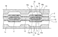
図3に示すように、ラミネートフィルム2及び3でシールされる2つのタブ端子5は、断面形状で、四つの縁部6aから6dがすべて曲面として形成されている。接合面13で上下から接合されるラミネートフィルム2及び3は、融着性樹脂層12を接合面13側に配置して、封止部8においてタブ端子5を封止している。
As shown in FIG. 3, the two
タブ端子5の封止は、封止部8の上下に設けた一対の型としてのヒートツール14及び15により行われる。ヒートツール14及び15は、それぞれタブ端子5に対向し、タブ端子5の外形形状に相補的な凹部16及び17を備えている。凹部16は、縁部6a及び6bの曲面に対応した曲面として形成された縁部14a及び14bを有する。また、凹部17は、縁部6c及び6dの曲面に対応した曲面として形成された縁部15a及び15bを有する。
The
タブ端子5は、周縁部7でラミネートフィルム2,3と対向する対向面5e、5eを備えている。タブ端子5の縁部6a、6b、6c及び6dは対向面5eに対して傾斜する曲面を有する。
The
以上のような構成のヒートツール14及び15は、タブ端子5を封止する封止部8を凹部16と凹部17との間に挟み込み、上下から加圧及び加熱する。このとき、タブ端子5の縁部5a乃至5dが、ヒートツール14及び15の対応する縁部14a及び14b、縁部15a及び15bと相補的な形状を有するため、タブ端子5の全ての縁部5a乃至5dがヒートツールと接触するようになる。これにより、タブ端子を含む封止部8の一辺全体にヒートツール14及び15から均一な圧力が加わり、シール品質が向上する。
The
図4は、タブ端子5の縁部の別形状の例を示している。図4に示すように、ラミネートフィルム2及び3で封止される2つのタブ端子5は、断面形状で、四つの縁部5aから5dがすべてテーパ面として形成されている。図4の例と同様に、接合面13で上下から接合されるラミネートフィルム2及び3は、融着性樹脂層12を接合面13側に配置して、封止部8においてタブ端子5を封止している。
FIG. 4 shows an example of another shape of the edge portion of the
図3及び図4に示すように、タブ端子5は、周縁部7に接触し熱溶着される部分に、予め第2の熱溶着性樹脂層51が形成されている。
As shown in FIG. 3 and FIG. 4, the
ヒートツール14及び15は、それぞれタブ端子5に対向し、タブ端子5の外形形状に相補的な凹部16及び17を備えている。凹部16は、縁部6a及び6bのテーパ面に対応したテーパ面として形成された縁部14a及び14bを有する。また、凹部17は、縁部6c及び6dのテーパ面に対応したテーパ面として形成された縁部15a及び15bを有する。各テーパ面は、接合面13に対して所定の角度をもっている。
The
前述のようにタブ端子5は、周縁部7でラミネートフィルム2,3と対向する対向面5e、5eを備えている。本例においては、タブ端子5の縁部6a、6b、6c及び6dは対向面5eに対して傾斜するテーパ面を有する。
As described above, the
図4の場合でも、タブ端子5の縁部5a乃至5dが、ヒートツール14及び15の対応する縁部14a及び14b、縁部15a及び15bと相補的な形状を有するため、タブ端子5の全ての縁部5a乃至5dがヒートツールと接触するようになる。これにより、タブ端子を含む封止部8の一辺全体にヒートツール14及び15から均一な圧力が加わり、シール品質が向上する。
Even in the case of FIG. 4, since the
図5は、本発明の他の実施形態に係るタブ端子の縁部の形状を示す断面図である。タブ端子5の縁部6a、6b、6c及び6dは、対向面5eに対して外側方向に凹凸を有するように形成されている。縁部6a、6b、6c及び6dをこのような形状とすることで、タブ端子5が融着樹脂層12、51に接触する部分での電解液漏れを堰き止めることができる。
FIG. 5 is a cross-sectional view showing the shape of the edge of a tab terminal according to another embodiment of the present invention. Edge portions 6a, 6b, 6c and 6d of the
図6は、本発明の他の実施形態に係るタブ端子の斜視図である。また、図7は、図6に示す本発明の他の実施形態に係る蓄電デバイスの部分断面図であり、図1のA−A線に沿った部位の断面図である。 FIG. 6 is a perspective view of a tab terminal according to another embodiment of the present invention. 7 is a partial cross-sectional view of the electricity storage device according to another embodiment of the present invention shown in FIG. 6, and is a cross-sectional view of a portion along the line AA in FIG.
この実施態様では、タブ端子5の縁部には曲面もテーパ面も形成されていない。しかしながら、タブ端子5の上下の対向面5eに凹凸形状が形成されている。図7は、その一例を示し、断面が三角形である複数の溝が設けられている。上面には溝20が、下面には溝21が設けられている。溝20及び21は、タブ端子5の長手方向と直交する方向であって、封止部8に対応した領域にタブ端子5の全幅に渡って設けられている。
In this embodiment, neither the curved surface nor the tapered surface is formed at the edge of the
本実施態様では、溝20及び21は、それぞれ4本設けられているが、溝の数は必要に応じて任意に設定できる。また、溝の深さ、断面形状なども同様である。図4及び図7に示すように、タブ端子5の溝20を設けた上面とラミネートフィルム2との間にシーラント22が配置されている。図4及び7ではタブ端子5の下面に設けるシーラントとラミネートフィルム3は図示を省略してある。また、対向面5eに設けた溝20,21は、本発明の全ての実施例のタブ端子5に設けることができる。
In this embodiment, four
平坦な面を有する公知のヒートツールにより封止部8がシーラント22と共に加圧及び加熱され、タブ端子5がラミネートフィルムで封止される。溝20及び21による凹凸構造により、蓄電デバイス1から電解液が漏れることを防止できる。特に、溝20及び21の凹部にシーラント22や融着性樹脂層12が食い込むことで、シール性が向上する。
The sealing
以下、本発明の蓄電デバイスの封止方法、すなわちタブ端子を含む一辺の封止方法を説明する。 Hereinafter, a method for sealing an electricity storage device of the present invention, that is, a method for sealing one side including a tab terminal will be described.
ラミネートフィルム2及び3で電池要素11を包囲した蓄電デバイス1を封止するには、複数の電池4とセパレータ10からなる電池要素11に接触してタブ端子5を配置する。次に、ラミネートフィルム2及び3で電池要素11及びタブ端子5を上下から包囲し、タブ端子5のリード部6を露出した状態で周縁部7においてラミネートフィルム2とラミネートフィルム3とを対向させる。タブ端子5の一部であるリード部6を周縁部7より外側に配置させる。この状態で、周縁部7を一対のヒートツール14及び15で加圧及び加熱する。
In order to seal the
ヒートツール14及び15による加圧及び加熱の直前、またはそれと同時に、周縁部7から露出したタブ端子5のリード部6を加熱する。これにより、ヒートツールからのタブ端子への放熱を防ぎ、タブ端子を含まない辺と同条件でシールすることが可能となる。また、三辺同時に封止することが可能となり、ラミネートシール工程の工数低減効果が得られる。
The
このとき、ヒートツール14及び15による加圧及び加熱は、図1に示した電解液封入用の開口部9を除く3つの封止部8、つまり蓄電デバイス1の3辺同時に行われる。従来のように一辺ずつ封止した場合に発生するシール端部が二重で熱履歴を受けることがなくなり、過剰シールによるラミネート間の短絡等々の品質不良が防げる。
At this time, the pressurization and heating by the
ここで、周縁部7より外側に露出するタブ端子5の他端であるリード部6を加熱するタブ端子加熱工程を説明する。以下、タブ端子5の露出したリード部6への入熱機構を三例説明する。蓄電デバイス1の基本的な構成は同じであるため、入熱に関する部分のみを説明する。図8は、本発明の蓄電デバイスの封止方法に係る入熱方法の一例を示す断面図である。ラミネートフィルム2及び3から露出したタブ端子5のリード部6は、入熱用のヒートツール30及び31に上下から挟まれる状態でヒートツール30及び31に接触している。タブ端子加熱工程は、ヒートツール14及び15による加圧及び加熱工程の間、または直後に行われる。
Here, the tab terminal heating process which heats the
入熱用のヒートツール30及び31が発生する熱がリード部6に伝達されることでタブ端子5全体が加熱される。これにより、ヒートツール14及び15によるタブ端子5が封止される辺の加熱量を他の2辺と同じにすることができ、三辺同時に封止することが可能となる。入熱用のヒートツール30及び31は、ラミネートフィルム2及び3の封止に使われるものと同じヒートツールを使うこともできる。
The heat generated by the heat
図9は、本発明の蓄電デバイスの封止方法に係る入熱方法の他例を示す断面図である。図9の例では、リード部6の上下に一対の赤外線照射器32及び33を配置している。赤外線照射器32及び33は、タブ端子5のリード部6に非接触である。赤外線照射器32及び33からの赤外線がリード部6に照射されることで、リード部6に熱が発生し、その熱はタブ端子5に伝達される。これによりタブ端子5全体が加熱される。従って、ヒートツール14及び15によるタブ端子5が封止される辺の加熱量を他の2辺と同じにすることができ、三辺同時に封止することが可能となる。
FIG. 9 is a cross-sectional view showing another example of the heat input method according to the method for sealing an electricity storage device of the present invention. In the example of FIG. 9, a pair of
図10は、本発明の蓄電デバイスの封止方法に係る入熱方法の更に他の例を示す断面図である。図10の例では、リード部6の上下に一対の熱風発生器34及び35を配置している。熱風発生器34及び35は、タブ端子5のリード部6に非接触である。熱風発生器34及び35からの熱風がリード部6に加えられることで、リード部6に熱が発生し、その熱はタブ端子5に伝達される。これによりタブ端子5全体が加熱される。従って、ヒートツール14及び15によるタブ端子5が封止される辺の加熱量を他の2辺と同じにすることができ、三辺同時に封止することが可能となる。
FIG. 10 is a cross-sectional view showing still another example of the heat input method according to the method for sealing an electricity storage device of the present invention. In the example of FIG. 10, a pair of
タブ端子を含む一辺では、ヒートツールから入熱された熱がラミネートだけでなくタブ端子にまで放熱していくため、タブ端子のない辺とでは最適な入熱容量が異なっていた。従って、タブ端子を含む辺と含まない辺の入熱条件を変えてシールする必要があるため、従来は一辺ずつシールを行っていたが、本発明によれば、上述のように三辺同時に封止することが可能となる。 On one side including the tab terminal, the heat input from the heat tool dissipates not only to the laminate but also to the tab terminal, so the optimum heat input capacity differs from the side without the tab terminal. Therefore, since it is necessary to seal by changing the heat input conditions of the side including the tab terminal and the side not including the tab terminal, conventionally, the sealing is performed one by one. However, according to the present invention, the three sides are sealed simultaneously as described above. It is possible to stop.
更に、蓄電デバイスへの電解液注入工程前のタブ端子が配置された辺を含み三辺あるラミネートの封止をタブ端子への入熱機構を加えることで、品質を確保しながら三辺同時に封止することができ、工程の削減が可能となる。 In addition, by adding a heat input mechanism to the tab terminal, sealing the three sides at the same time while ensuring the quality by sealing the laminate with three sides including the side where the tab terminal is placed before the electrolyte injection process to the electricity storage device. The process can be reduced.
シール直前またはシール中にタブ端子に入熱する機構を加えることで、ヒートツールからのタブ端子への放熱を防ぎ、タブ端子を含まない辺と同条件でシールすることが可能となる。これにより、三辺同時に封止することが可能となり、ラミネートフィルムの封止工程の工数低減効果が得られる。 By adding a mechanism for heat input to the tab terminal immediately before or during sealing, heat radiation from the heat tool to the tab terminal can be prevented, and sealing can be performed under the same conditions as the side not including the tab terminal. Thereby, it becomes possible to seal three sides simultaneously, and the man-hour reduction effect of the sealing process of a laminate film is acquired.
更に、従来のように一辺ずつ三辺を封止した場合にはシール端部が二重で熱履歴を受けるため、過剰シールによるラミネート間の短絡等の品質不良が懸念されるが、三辺を同時に封止することでこれを回避できるため、品質の向上効果も得られる。 In addition, when three sides are sealed one by one as in the past, the seal ends receive double heat history, so there is a concern about quality defects such as short circuit between laminates due to excessive sealing. Since this can be avoided by sealing at the same time, a quality improvement effect can also be obtained.
タブ端子5に入熱する手段としては、赤外線照射器や熱風発生器に代えて超音波発生器なども用いることができる。
As a means for heat input to the
1:蓄電デバイス、2:ラミネートフィルム、3:ラミネートフィルム、5、タブ端子、4:電極、5a〜5d:縁部、5e:対向面、6:リード部、7:周縁部、8:封止部、11:電池要素、12、51:融着性樹脂層、14:ヒートツール、15:ヒートツール、20:溝、21:溝、30:ヒートツール、31:ヒートツール、32:赤外線照射器、33:赤外線照射器、34:熱風発生器、35:熱風発生器 1: Power storage device, 2: Laminate film, 3: Laminate film, 5, Tab terminal, 4: Electrode, 5a to 5d: Edge, 5e: Opposing surface, 6: Lead part, 7: Peripheral part, 8: Sealing Part, 11: battery element, 12, 51: fusible resin layer, 14: heat tool, 15: heat tool, 20: groove, 21: groove, 30: heat tool, 31: heat tool, 32: infrared irradiator 33: Infrared irradiator, 34: Hot air generator, 35: Hot air generator
Claims (5)
前記ラミネートフィルムに包囲された電池要素と、
前記電池要素に一端が接合され、他端が前記周縁部から露出するタブ端子と、を備える蓄電デバイスにおいて、
前記タブ端子は、前記周縁部で、前記ラミネートフィルムと対向する対向面と、前記対向面に対して傾斜する曲面またはテーパ面となる縁部とを有する、ことを特徴とする蓄電デバイス。 A laminate film whose periphery is thermally welded;
A battery element surrounded by the laminate film;
In a power storage device comprising: a tab terminal having one end joined to the battery element and the other end exposed from the peripheral edge;
The tab terminal has an opposing surface that faces the laminate film at the peripheral edge portion, and an edge portion that becomes a curved surface or a tapered surface inclined with respect to the opposing surface.
前記タブ端子を準備する工程と、
前記タブ端子の一端に接合される電池要素を前記ラミネートで包囲し、前記タブ端子の他端を前記周縁部より外側に配置させる工程と、
前記周縁部に、一対の型で加圧しながら熱を加える加熱工程を含み、
前記タブ端子を準備する工程では、前記周縁部で、前記ラミネートフィルムと対向する対向面と、前記対向面に対して傾斜する曲面またはテーパ面となる縁部とを有するタブ端子を準備することを特徴とする蓄電デバイスの封止方法。 In the sealing method of the electricity storage device in which the tab terminal is exposed from the laminate film on which the peripheral edge is thermally welded,
Preparing the tab terminal;
Surrounding the battery element joined to one end of the tab terminal with the laminate, and disposing the other end of the tab terminal outside the peripheral portion;
A heating step of applying heat to the peripheral portion while applying pressure with a pair of molds;
In the step of preparing the tab terminal, preparing a tab terminal having an opposing surface facing the laminate film and an edge portion that becomes a curved surface or a tapered surface inclined with respect to the opposing surface at the peripheral edge. A method for sealing an electricity storage device.
Priority Applications (1)
| Application Number | Priority Date | Filing Date | Title |
|---|---|---|---|
| JP2012063352A JP2013196930A (en) | 2012-03-21 | 2012-03-21 | Power storage device and encapsulation method of power storage device |
Applications Claiming Priority (1)
| Application Number | Priority Date | Filing Date | Title |
|---|---|---|---|
| JP2012063352A JP2013196930A (en) | 2012-03-21 | 2012-03-21 | Power storage device and encapsulation method of power storage device |
Publications (1)
| Publication Number | Publication Date |
|---|---|
| JP2013196930A true JP2013196930A (en) | 2013-09-30 |
Family
ID=49395629
Family Applications (1)
| Application Number | Title | Priority Date | Filing Date |
|---|---|---|---|
| JP2012063352A Pending JP2013196930A (en) | 2012-03-21 | 2012-03-21 | Power storage device and encapsulation method of power storage device |
Country Status (1)
| Country | Link |
|---|---|
| JP (1) | JP2013196930A (en) |
Cited By (6)
| Publication number | Priority date | Publication date | Assignee | Title |
|---|---|---|---|---|
| WO2015012195A1 (en) * | 2013-07-22 | 2015-01-29 | 株式会社村田製作所 | Method for fabrication of laminated electrical storage device |
| KR20170110300A (en) * | 2016-03-23 | 2017-10-11 | 주식회사 엘지화학 | Method for Manufacturing Battery Cell by Pre-Heating Electrode Lead |
| CN108281577A (en) * | 2018-02-28 | 2018-07-13 | 河南国能电池有限公司 | Soft-package battery closedtop end socket |
| CN110739434A (en) * | 2018-07-20 | 2020-01-31 | 宁德新能源科技有限公司 | Utmost point ear, electric core and battery |
| JP2021057249A (en) * | 2019-09-30 | 2021-04-08 | 積水化学工業株式会社 | Method for manufacturing laminated battery, device for manufacturing laminated battery, and laminated battery |
| JP6965983B1 (en) * | 2020-12-17 | 2021-11-10 | 大日本印刷株式会社 | Power storage devices, electrical equipment and electrode terminal parts |
Citations (6)
| Publication number | Priority date | Publication date | Assignee | Title |
|---|---|---|---|---|
| JP2001102034A (en) * | 1999-09-29 | 2001-04-13 | Matsushita Electric Ind Co Ltd | Method of using lead line for battery, battery of thin film type using the lead line, and lead line for battery |
| JP2005056815A (en) * | 2003-07-22 | 2005-03-03 | Toyota Motor Corp | Secondary battery and fabrication method thereof |
| JP2006099970A (en) * | 2004-09-28 | 2006-04-13 | Nec Tokin Tochigi Ltd | Sealing method and sealing device of lead terminal part |
| JP2008251464A (en) * | 2007-03-30 | 2008-10-16 | Tdk Corp | Electrochemical element |
| JP2010087363A (en) * | 2008-10-01 | 2010-04-15 | Taiyo Yuden Co Ltd | Electrochemical device |
| JP2011086834A (en) * | 2009-10-16 | 2011-04-28 | Tdk Corp | Electrochemical device and method of manufacturing the same |
-
2012
- 2012-03-21 JP JP2012063352A patent/JP2013196930A/en active Pending
Patent Citations (6)
| Publication number | Priority date | Publication date | Assignee | Title |
|---|---|---|---|---|
| JP2001102034A (en) * | 1999-09-29 | 2001-04-13 | Matsushita Electric Ind Co Ltd | Method of using lead line for battery, battery of thin film type using the lead line, and lead line for battery |
| JP2005056815A (en) * | 2003-07-22 | 2005-03-03 | Toyota Motor Corp | Secondary battery and fabrication method thereof |
| JP2006099970A (en) * | 2004-09-28 | 2006-04-13 | Nec Tokin Tochigi Ltd | Sealing method and sealing device of lead terminal part |
| JP2008251464A (en) * | 2007-03-30 | 2008-10-16 | Tdk Corp | Electrochemical element |
| JP2010087363A (en) * | 2008-10-01 | 2010-04-15 | Taiyo Yuden Co Ltd | Electrochemical device |
| JP2011086834A (en) * | 2009-10-16 | 2011-04-28 | Tdk Corp | Electrochemical device and method of manufacturing the same |
Cited By (13)
| Publication number | Priority date | Publication date | Assignee | Title |
|---|---|---|---|---|
| JP6004112B2 (en) * | 2013-07-22 | 2016-10-05 | 株式会社村田製作所 | Manufacturing method of laminate-type electricity storage device |
| JPWO2015012195A1 (en) * | 2013-07-22 | 2017-03-02 | 株式会社村田製作所 | Manufacturing method of laminate-type electricity storage device |
| US10193180B2 (en) | 2013-07-22 | 2019-01-29 | Murata Manufacturing Co., Ltd. | Method for manufacturing laminated electrical storage device |
| WO2015012195A1 (en) * | 2013-07-22 | 2015-01-29 | 株式会社村田製作所 | Method for fabrication of laminated electrical storage device |
| KR102120084B1 (en) * | 2016-03-23 | 2020-06-08 | 주식회사 엘지화학 | Method for Manufacturing Battery Cell by Pre-Heating Electrode Lead |
| KR20170110300A (en) * | 2016-03-23 | 2017-10-11 | 주식회사 엘지화학 | Method for Manufacturing Battery Cell by Pre-Heating Electrode Lead |
| CN108281577A (en) * | 2018-02-28 | 2018-07-13 | 河南国能电池有限公司 | Soft-package battery closedtop end socket |
| CN110739434A (en) * | 2018-07-20 | 2020-01-31 | 宁德新能源科技有限公司 | Utmost point ear, electric core and battery |
| JP2021057249A (en) * | 2019-09-30 | 2021-04-08 | 積水化学工業株式会社 | Method for manufacturing laminated battery, device for manufacturing laminated battery, and laminated battery |
| JP7299816B2 (en) | 2019-09-30 | 2023-06-28 | 積水化学工業株式会社 | Stacked battery manufacturing method, stacked battery manufacturing apparatus, and stacked battery |
| JP6965983B1 (en) * | 2020-12-17 | 2021-11-10 | 大日本印刷株式会社 | Power storage devices, electrical equipment and electrode terminal parts |
| WO2022130973A1 (en) * | 2020-12-17 | 2022-06-23 | 大日本印刷株式会社 | Power storage device, electric apparatus, electrode terminal component, and method for manufacture of same |
| JP2022096220A (en) * | 2020-12-17 | 2022-06-29 | 大日本印刷株式会社 | Power storage device, electrical machine, and electrode terminal component |
Similar Documents
| Publication | Publication Date | Title |
|---|---|---|
| US11276903B2 (en) | Electricity storage device and method for manufacturing electricity storage device | |
| JP2013196930A (en) | Power storage device and encapsulation method of power storage device | |
| JP7038961B2 (en) | How to seal the side part of the pouch type battery including the two-step sealing process | |
| KR101852250B1 (en) | Sealing tool for a pouch type secondary battery | |
| US20170012252A1 (en) | Battery cell having outer edge sealed portion with sealed lines and battery cell sealing apparatus for manufacture thereof | |
| JP6678768B2 (en) | Method of manufacturing film-covered battery and film-covered battery | |
| JP6019224B2 (en) | Manufacturing method and manufacturing apparatus for laminate type secondary battery | |
| US10193180B2 (en) | Method for manufacturing laminated electrical storage device | |
| KR20120083287A (en) | Galvanic cell comprising frame, and method for the production thereof | |
| WO2020203101A1 (en) | Power storage module | |
| US9048463B2 (en) | Pouch-cell battery arrangement and corresponding production method and use | |
| JP2014032924A (en) | Film sheathed battery and method for manufacturing the same | |
| RU2439732C2 (en) | Duodielectric capacitor | |
| JP6491548B2 (en) | Secondary battery manufacturing method and manufacturing apparatus | |
| CN110380080B (en) | Resin frame-equipped electrolyte membrane-electrode assembly for fuel cell | |
| CN104051679A (en) | Electrochemical cell and manufacturing method thereof | |
| KR101390139B1 (en) | Pouch type secondary battery | |
| KR102348074B1 (en) | Pouch sealing apparatus and method of manufacturing secondary battery | |
| JP2017154760A (en) | Seal bar, seal bar system, and method of manufacturing bag-like article | |
| KR101514654B1 (en) | Sealing Apparatus easy to discharge gas for Battery cell | |
| KR102455141B1 (en) | Electrode Assembly Manufacturing Method for Battery Cell of Secondary Battery | |
| WO2014178238A1 (en) | Laminate-type secondary battery manufacturing device and manufacturing method | |
| CN107293652B (en) | Packaging seal structure, preparation method thereof and flexible packaging battery | |
| JP2017152140A (en) | Secondary battery, seal bar, and method of manufacturing secondary battery | |
| JP7110946B2 (en) | Dies for joining fuel cell single cells |
Legal Events
| Date | Code | Title | Description |
|---|---|---|---|
| A621 | Written request for application examination |
Free format text: JAPANESE INTERMEDIATE CODE: A621 Effective date: 20150210 |
|
| A977 | Report on retrieval |
Free format text: JAPANESE INTERMEDIATE CODE: A971007 Effective date: 20151130 |
|
| A131 | Notification of reasons for refusal |
Free format text: JAPANESE INTERMEDIATE CODE: A131 Effective date: 20151201 |
|
| A02 | Decision of refusal |
Free format text: JAPANESE INTERMEDIATE CODE: A02 Effective date: 20160405 |