JP2013183221A - Radio communication device and interference detection method - Google Patents
Radio communication device and interference detection method Download PDFInfo
- Publication number
- JP2013183221A JP2013183221A JP2012044369A JP2012044369A JP2013183221A JP 2013183221 A JP2013183221 A JP 2013183221A JP 2012044369 A JP2012044369 A JP 2012044369A JP 2012044369 A JP2012044369 A JP 2012044369A JP 2013183221 A JP2013183221 A JP 2013183221A
- Authority
- JP
- Japan
- Prior art keywords
- carrier sense
- busy
- wireless communication
- unit
- time
- Prior art date
- Legal status (The legal status is an assumption and is not a legal conclusion. Google has not performed a legal analysis and makes no representation as to the accuracy of the status listed.)
- Granted
Links
- 238000004891 communication Methods 0.000 title claims abstract description 199
- 238000001514 detection method Methods 0.000 title claims description 9
- 230000005540 biological transmission Effects 0.000 claims abstract description 97
- 238000000034 method Methods 0.000 claims description 79
- 230000008569 process Effects 0.000 claims description 56
- 230000004044 response Effects 0.000 claims description 39
- 238000010586 diagram Methods 0.000 description 14
- 230000035945 sensitivity Effects 0.000 description 13
- 230000008859 change Effects 0.000 description 5
- 238000006243 chemical reaction Methods 0.000 description 4
- 230000006835 compression Effects 0.000 description 3
- 238000007906 compression Methods 0.000 description 3
- 230000006837 decompression Effects 0.000 description 3
- 101100172132 Mus musculus Eif3a gene Proteins 0.000 description 2
- 230000006978 adaptation Effects 0.000 description 2
- 238000005516 engineering process Methods 0.000 description 2
- 230000007246 mechanism Effects 0.000 description 2
- 238000009825 accumulation Methods 0.000 description 1
- 230000004913 activation Effects 0.000 description 1
- 230000003466 anti-cipated effect Effects 0.000 description 1
- 230000008901 benefit Effects 0.000 description 1
- 230000000694 effects Effects 0.000 description 1
- 230000005611 electricity Effects 0.000 description 1
- 238000012986 modification Methods 0.000 description 1
- 230000004048 modification Effects 0.000 description 1
- 230000000630 rising effect Effects 0.000 description 1
- 230000008054 signal transmission Effects 0.000 description 1
Images


Classifications
-
- H—ELECTRICITY
- H04—ELECTRIC COMMUNICATION TECHNIQUE
- H04W—WIRELESS COMMUNICATION NETWORKS
- H04W74/00—Wireless channel access, e.g. scheduled or random access
- H04W74/08—Non-scheduled or contention based access, e.g. random access, ALOHA, CSMA [Carrier Sense Multiple Access]
- H04W74/0808—Non-scheduled or contention based access, e.g. random access, ALOHA, CSMA [Carrier Sense Multiple Access] using carrier sensing, e.g. as in CSMA
- H04W74/0816—Non-scheduled or contention based access, e.g. random access, ALOHA, CSMA [Carrier Sense Multiple Access] using carrier sensing, e.g. as in CSMA carrier sensing with collision avoidance
-
- G—PHYSICS
- G08—SIGNALLING
- G08B—SIGNALLING OR CALLING SYSTEMS; ORDER TELEGRAPHS; ALARM SYSTEMS
- G08B5/00—Visible signalling systems, e.g. personal calling systems, remote indication of seats occupied
- G08B5/22—Visible signalling systems, e.g. personal calling systems, remote indication of seats occupied using electric transmission; using electromagnetic transmission
- G08B5/36—Visible signalling systems, e.g. personal calling systems, remote indication of seats occupied using electric transmission; using electromagnetic transmission using visible light sources
-
- H—ELECTRICITY
- H04—ELECTRIC COMMUNICATION TECHNIQUE
- H04B—TRANSMISSION
- H04B17/00—Monitoring; Testing
- H04B17/30—Monitoring; Testing of propagation channels
- H04B17/309—Measuring or estimating channel quality parameters
- H04B17/318—Received signal strength
-
- H—ELECTRICITY
- H04—ELECTRIC COMMUNICATION TECHNIQUE
- H04B—TRANSMISSION
- H04B17/00—Monitoring; Testing
- H04B17/30—Monitoring; Testing of propagation channels
- H04B17/309—Measuring or estimating channel quality parameters
- H04B17/345—Interference values
-
- H—ELECTRICITY
- H04—ELECTRIC COMMUNICATION TECHNIQUE
- H04J—MULTIPLEX COMMUNICATION
- H04J11/00—Orthogonal multiplex systems, e.g. using WALSH codes
- H04J11/0023—Interference mitigation or co-ordination
-
- H—ELECTRICITY
- H04—ELECTRIC COMMUNICATION TECHNIQUE
- H04W—WIRELESS COMMUNICATION NETWORKS
- H04W24/00—Supervisory, monitoring or testing arrangements
- H04W24/02—Arrangements for optimising operational condition
-
- H—ELECTRICITY
- H04—ELECTRIC COMMUNICATION TECHNIQUE
- H04W—WIRELESS COMMUNICATION NETWORKS
- H04W24/00—Supervisory, monitoring or testing arrangements
- H04W24/08—Testing, supervising or monitoring using real traffic
-
- H—ELECTRICITY
- H04—ELECTRIC COMMUNICATION TECHNIQUE
- H04W—WIRELESS COMMUNICATION NETWORKS
- H04W74/00—Wireless channel access, e.g. scheduled or random access
- H04W74/08—Non-scheduled or contention based access, e.g. random access, ALOHA, CSMA [Carrier Sense Multiple Access]
- H04W74/0808—Non-scheduled or contention based access, e.g. random access, ALOHA, CSMA [Carrier Sense Multiple Access] using carrier sensing, e.g. as in CSMA
-
- H—ELECTRICITY
- H04—ELECTRIC COMMUNICATION TECHNIQUE
- H04W—WIRELESS COMMUNICATION NETWORKS
- H04W84/00—Network topologies
- H04W84/02—Hierarchically pre-organised networks, e.g. paging networks, cellular networks, WLAN [Wireless Local Area Network] or WLL [Wireless Local Loop]
- H04W84/10—Small scale networks; Flat hierarchical networks
- H04W84/12—WLAN [Wireless Local Area Networks]
Abstract
Description
本発明の実施形態は、無線通信装置及び干渉検出方法に関する。 Embodiments described herein relate generally to a wireless communication apparatus and an interference detection method.
現在、ミリ波帯を使用する高速伝送のための無線システム技術として、ワイヤレスHD(WirelessHD)規格の策定が完了しており、また、従来の無線ローカルエリアネットワーク(特に802.11a/b/g)について、そのような無線システム技術の規格化も進んでいる。ミリ波帯を使用する無線システムにとって、同一周波数帯域における他の無線システムとの共存或いは干渉検出が課題になっている。 Currently, the wireless HD (WirelessHD) standard has been established as a wireless system technology for high-speed transmission using the millimeter wave band, and a conventional wireless local area network (especially 802.11a / b / g) As for standardization of such wireless system technology, progress is being made. For wireless systems that use the millimeter wave band, coexistence with other wireless systems in the same frequency band or interference detection is an issue.
従来の無線LANでは、CSMA/CA方式によるアクセス制御が行われる。このアクセス制御によれば、個々の無線通信装置が、無線チャネルを使用する前に無線チャネルの占有状態を測定及び検出し、送信前にランダムにバックオフを設定することによって、複数の無線通信装置の間で帯域を公平に使用することが可能となる。 In a conventional wireless LAN, access control by the CSMA / CA method is performed. According to this access control, each wireless communication device measures and detects the occupied state of the wireless channel before using the wireless channel, and randomly sets a backoff before transmission, so that a plurality of wireless communication devices are set. It is possible to use the bandwidth fairly between the two.
これに対して、近距離無線通信では、むしろ接続の簡易化且つ効率化を重視した手法が期待される。しかしながら、近距離通信において、近距離の無線通信装置同士のみが接続処理を行うようにキャリアセンスの感度点を高く設定する場合に、送受信での誤り発生時に、その原因が、干渉によるものか或いは例えば近距離通信を行う無線通信装置同士の状況のような他の要因によるものかを判定することが難しかった。 On the other hand, in short-range wireless communication, a method that emphasizes simplified and efficient connection is expected. However, in short-range communication, when the carrier sense sensitivity point is set high so that only short-range wireless communication devices perform connection processing, when an error occurs in transmission / reception, the cause is due to interference or For example, it is difficult to determine whether it is due to other factors such as the situation of wireless communication devices that perform short-range communication.
近距離無線通信において送受信での誤り発生時にその原因が干渉にあるか否か判定することは難しかった。それゆえ、誤り発生時に干渉を回避するための処理を行うか否かを判定することが難しかった。 It has been difficult to determine whether or not the cause is interference when an error occurs in transmission and reception in short-range wireless communication. Therefore, it is difficult to determine whether or not to perform processing for avoiding interference when an error occurs.
本実施形態は、近距離無線通信において送受信での誤り発生時に干渉を回避するための処理を行うか否か判定することを可能にする無線通信装置及び干渉検出方法を提供することを目的とする。 An object of the present embodiment is to provide a wireless communication apparatus and an interference detection method that can determine whether or not to perform processing for avoiding interference when an error occurs in transmission and reception in short-range wireless communication. .
実施形態によれば、第1の判定部と、第2の判定部とを備える。第1の判定部は、第1のキャリアセンス閾値を用いてビジーか否かを判定し、前記第1のキャリアセンス閾値を用いてビジーと判定された第1時刻を特定し、前記第1のキャリアセンス閾値よりも値が小さい第2のキャリアセンス閾値を用いてビジーか否かを判定し、前記第2のキャリアセンス閾値を用いてビジーと判定された第2時刻を特定する。第2の判定部は、少なくとも、前記第2のキャリアセンス閾値を用いてビジーと判定され、且つ、前記第2時刻が、前記第1時刻以前の基準時刻より前である場合に、干渉を回避するための処理を行うと判定する。 According to the embodiment, a first determination unit and a second determination unit are provided. A first determination unit configured to determine whether the first carrier sense threshold is busy, to determine a first time determined to be busy using the first carrier sense threshold; Whether or not busy is determined using a second carrier sense threshold value smaller than the carrier sense threshold value, and a second time determined to be busy is specified using the second carrier sense threshold value. The second determination unit avoids interference when at least the second carrier sense threshold is determined to be busy and the second time is before a reference time before the first time. It is determined that the process for performing is performed.
以下、図面を参照しながら本発明の実施形態に係る無線通信装置について詳細に説明する。なお、以下の実施形態では、同一の番号を付した部分については同様の動作を行うものとして、重ねての説明を省略する。 Hereinafter, a wireless communication apparatus according to an embodiment of the present invention will be described in detail with reference to the drawings. Note that, in the following embodiments, the same numbered portions are assumed to perform the same operation, and repeated description is omitted.
さて、前述のように、従来の無線LANでは、干渉回避及び無線帯域の公平性を重視するために、CSMA/CA方式によるアクセス制御が行われる。 As described above, in the conventional wireless LAN, access control by the CSMA / CA method is performed in order to emphasize interference avoidance and fairness of the wireless band.
これに対して、例えば通信範囲が広くて数10cm程度であるような近距離無線通信を使用する無線通信システムを仮定した場合、そのような近距離無線通信では、その通信範囲に入る無線通信装置同士のみが影響し合う。それゆえ、上記のような干渉回避及び無線帯域の公平性を重視する手法ではなく、例えば、ある一つの無線通信装置がアクセスポイントとしてブロードキャスト信号(例えばビーコン信号)を送信し、各無線通信装置が送信する度にランダムバックオフ制御を行うような手法ではなく、むしろ接続の簡易化且つ効率化を重視した手法が期待される。 On the other hand, for example, assuming a wireless communication system that uses short-range wireless communication with a wide communication range of about several tens of centimeters, in such short-range wireless communication, a wireless communication device that falls within the communication range is used. Only one another affects each other. Therefore, it is not a technique that places importance on interference avoidance and radio band fairness as described above. For example, one wireless communication apparatus transmits a broadcast signal (for example, a beacon signal) as an access point, and each wireless communication apparatus Rather than a method that performs random backoff control every time it is transmitted, a method that emphasizes simplified and efficient connection is expected.
上記の近距離通信を仮定した場合、近距離の無線通信装置同士のみが接続処理を行うように、キャリアセンスの感度点が高く設定される場合がある。この場合、或る無線通信装置が、相手の無線通信装置に接続要求信号を送信し、該相手の無線通信装置が、感度点の高いキャリアセンス閾値により検出及び受信処理を行って、接続応答信号を送信することによって、それら2台の無線通信装置の間で通信が開始される。 Assuming the above short-range communication, the sensitivity point of carrier sense may be set high so that only short-range wireless communication devices perform connection processing. In this case, a certain wireless communication device transmits a connection request signal to the partner wireless communication device, and the partner wireless communication device performs detection and reception processing with a carrier sense threshold value having a high sensitivity point, and a connection response signal. Is transmitted between the two wireless communication devices.
しかしながら、近距離通信を仮定した感度点の高いキャリアセンスを用いると、「キャリアセンス(CCA)がアイドルと判定されるが、実際には他の無線通信システム等の影響で所要SINR(所要信号対雑音干渉電力比)を満たさない状況」が発生し得る。このような場合、キャリアセンス閾値での判定結果がアイドルであるため、送受信の誤り発生時において、送受信の誤りの原因が、干渉によるものか又は他の要因(例えば、近距離通信を行う無線通信装置同士の状況)によるものかを判定することが難しくなる。 However, when carrier sense with a high sensitivity point assuming short-range communication is used, “carrier sense (CCA) is determined to be idle, but actually, the required SINR (required signal pair A situation that does not satisfy the noise interference power ratio) may occur. In such a case, since the determination result at the carrier sense threshold is idle, when the transmission / reception error occurs, the cause of the transmission / reception error is due to interference or other factors (for example, wireless communication performing short-range communication) It becomes difficult to determine whether it is due to the situation between devices.
干渉による誤りか否かの判定方法として、「受信誤り発生」かつ「受信電力が干渉判定閾値以上」であるならば、干渉と判定し、そして、干渉と判定された場合には再送回数及び送信レートを制御する仕組みが考えられる。しかし、この干渉判定閾値として、キャリアセンス閾値を用いても、送受信の誤りの原因が、干渉にあるか否かを判定することはできない。 As a method for determining whether or not an error has occurred due to interference, if “reception error has occurred” and “reception power is equal to or greater than the interference determination threshold value”, it is determined as interference. A mechanism for controlling the rate is conceivable. However, even if a carrier sense threshold is used as the interference determination threshold, it cannot be determined whether or not the cause of transmission / reception errors is interference.
そこで、以下の各実施形態では、近距離無線通信において送受信での誤り発生時に干渉を回避するための処理を行うか否かの判定を可能とする。 Therefore, in each of the following embodiments, it is possible to determine whether or not to perform processing for avoiding interference when an error occurs in transmission and reception in short-range wireless communication.
ここで、「干渉を回避するための処理」とは、干渉を受けたときでも無線通信を継続できるようにするための処理であればどのようなものであっても良く、例えば、
・使用するチャネルを変更する
・送信レートを変更する
・ユーザへ通知する
・フレーム間隔を変更する
・それらの任意の組み合わせ
など様々な処理がある。
Here, the “process for avoiding interference” may be any process as long as wireless communication can be continued even when interference is received.
・ Change the channel to be used
・ Change the transmission rate
・ Notify users
・ Change the frame interval
・ Any combination of them
There are various processes.
(第1の実施形態)
図1に、第1〜第17の実施形態に係る無線通信システムの例を示す。図1の例では、無線通信システムに3台の無線通信装置1〜3が含まれる状態を例示している。ただし、無線通信システムに含まれる無線通信装置の台数は3台に限定されない。
(First embodiment)
In FIG. 1, the example of the radio | wireless communications system which concerns on 1st-17th embodiment is shown. In the example of FIG. 1, a state where three
本実施形態の無線通信システムの具体例として、例えば通信範囲が高々数10cm程度であるような近距離無線通信を使用するものが想定される。無線通信システムでは、そのような短い通信範囲に入る無線通信装置のみが影響し合うため、1台の無線通信装置に接続する無線通信装置の数は、高々数台になると想定される。例えば、図1において、無線通信装置1が、無線通信装置2と、1対1の無線通信装置間通信を行い、或いは、無線通信装置3と、1対1の局間通信を行い、或いは、無線通信装置2,3と、複数局間通信を行う。
As a specific example of the wireless communication system according to the present embodiment, one using short-range wireless communication having a communication range of about several tens of centimeters at most is assumed. In a wireless communication system, only wireless communication devices that fall within such a short communication range influence each other, so it is assumed that the number of wireless communication devices connected to one wireless communication device is at most several. For example, in FIG. 1, the
図1に示すような1対1無線通信装置間の近距離通信では、従来の無線LANのように干渉回避及び無線帯域の公平性を重視する手法よりも、むしろ接続の簡易化且つ効率化を重視した手法が期待される。その一つの手法として、フレーム送信を行う時には、例えば接続要求信号(Connect Request)及び接続応答信号(Connect Accept)のような接続を開始するための無線通信装置間の制御信号を送受信し、接続を確立する処理が終了した後は、送信信号の送信及びその応答信号(Ack、又は、BA(Block ACK))の受信を、例えばSIFS(short interframe space)のような短い一定時間を空けて繰り返すことが考えられる。また、このようなシステムを考えた場合、通信範囲以内に位置する無線通信装置からの接続要求のみに応答するという制限が必要である。例えば、信号検出のキャリアセンス閾値の感度点を高く設定することによって、上記制限を実現することが考えられる。 In short-distance communication between one-to-one wireless communication devices as shown in FIG. 1, rather than a technique that emphasizes interference avoidance and wireless band fairness as in a conventional wireless LAN, the connection is simplified and efficient. Expected to be an important method. As one of the techniques, when performing frame transmission, for example, a control signal between wireless communication devices for starting connection such as a connection request signal (Connect Request) and a connection response signal (Connect Accept) is transmitted and received. After the establishment process is completed, transmission of the transmission signal and reception of the response signal (Ack or BA (Block ACK)) are repeated with a short fixed time, such as SIFS (short interframe space). Can be considered. Further, when considering such a system, it is necessary to limit that only a connection request from a wireless communication device located within the communication range is responded. For example, it is conceivable to realize the above limitation by setting a high sensitivity point of the carrier sense threshold for signal detection.
一方、同一周波数帯域を用いる他の無線通信システムが存在する場合、上記のようなキャリアセンス閾値の感度点を高く設定したキャリアセンスを行っていると、「キャリアセンスではアイドルとなるが、他の無線通信システムからの干渉存在時に、その影響で、所要SINRを満たさない領域」が生じる可能性が高い。そのため、そのような領域においては、フレーム送信する無線通信装置は、送信前のキャリアセンスがアイドルであることを確認した後に送信したにもかかわらず、送信フレームに対する応答がない、といった問題が生じる。また、フレーム受信する無線通信装置でも、キャリアセンスはアイドルであるのにもかかわらず、受信したフレームが受信誤りとなるといった問題が生じる。そして、それが干渉に起因しているか、或いは、それ以外の要因(例えば、送受信する無線通信装置間の距離などのような他の問題)に起因しているかの切り分けが難しい。 On the other hand, when there is another wireless communication system using the same frequency band, if carrier sense with a high sensitivity point of the carrier sense threshold as described above is performed, “the carrier sense becomes idle, In the presence of interference from the radio communication system, there is a high possibility that a region that does not satisfy the required SINR will occur due to the influence. Therefore, in such a region, there arises a problem that a wireless communication apparatus that transmits a frame does not respond to a transmission frame even though it transmits after confirming that the carrier sense before transmission is idle. Even in a wireless communication apparatus that receives a frame, there is a problem that the received frame becomes a reception error even though the carrier sense is idle. It is difficult to determine whether it is caused by interference or other factors (for example, other problems such as a distance between wireless communication apparatuses that transmit and receive data).
そこで、第1の実施形態では、フレーム受信時に、2レベルのキャリアセンスを行うことによって、受信誤りが、干渉に起因しているか否かを判定できるようにする。 Therefore, in the first embodiment, it is possible to determine whether or not a reception error is caused by interference by performing two-level carrier sense at the time of frame reception.
まず、本実施形態における2種類(2レベル)のキャリアセンスを利用したアイドル/ビジー判定について説明する。 First, idle / busy determination using two types (two levels) of carrier sense in the present embodiment will be described.
ここで、2レベルのキャリアセンスは、第1のキャリアセンス閾値による第1のキャリアセンス及び第2のキャリアセンス閾値による第2のキャリアセンスである。 Here, the two-level carrier sense is a first carrier sense based on the first carrier sense threshold and a second carrier sense based on the second carrier sense threshold.
図2に、第1の実施形態において使用する第1のキャリアセンス及び第2のキャリアセンスによるアイドル/ビジーと判定時刻との関係図を示す。 FIG. 2 shows a relationship diagram between idle / busy and determination time by the first carrier sense and the second carrier sense used in the first embodiment.
図2において、CCA_1は、第1のキャリアセンスを示すものであり、CCA_2は、第2のキャリアセンスを示すものである。横軸は、時刻を示す。縦軸は、ロー・レベルがアイドル判定を示し、ハイ・レベルがビジー判定を示すものとする。 In FIG. 2, CCA_1 indicates a first carrier sense, and CCA_2 indicates a second carrier sense. The horizontal axis indicates time. In the vertical axis, a low level indicates an idle determination, and a high level indicates a busy determination.
判定は、例えば、常時行う方法と、例えば周期的に一定の期間だけ行う方法、指示されたときのみ一定の期間又は指示された期間だけ行う方法など、種々の方法が考えられ、いずれの方法を採ることも可能である。 For example, various methods are conceivable, such as a method that is always performed, a method that is periodically performed for a certain period, a method that is performed only when a certain period is specified, or a method that is performed only during a specified period. It is also possible to take.
第1のキャリアセンス閾値は、例えば、アイドル/ビジーを判定するための本来のキャリアセンスにおいて使用されるキャリアセンス閾値である。この場合、アイドル/ビジーの判定自体は、第1のキャリアセンスにより行うことができる。第2のキャリアセンス閾値は、例えば、第1のキャリアセンス閾値より感度点が低く設定されるキャリアセンス閾値である。すなわち、第2のキャリアセンスは、第1のキャリアセンスよりも感度点が低いキャリアセンスになる。第1及び第2のキャリアセンスを組み合わせて、受信誤りの原因が干渉にあるかどうか判定する。 The first carrier sense threshold is, for example, a carrier sense threshold used in original carrier sense for determining idle / busy. In this case, the idle / busy determination itself can be performed by the first carrier sense. The second carrier sense threshold is, for example, a carrier sense threshold set with a sensitivity point lower than that of the first carrier sense threshold. That is, the second carrier sense is a carrier sense having a sensitivity point lower than that of the first carrier sense. The first and second carrier senses are combined to determine whether the cause of the reception error is interference.
図2において、ケース1は、第1のキャリアセンスCCA_1のビジー判定時刻Tcca1と第2のキャリアセンスCCA_2のビジー判定時刻Tcca2とが同時(或いは、ほぼ同時)の場合である。ケース1においては、受信処理で受信誤りが検出された場合には、その原因が、干渉ではなく、当該無線通信を行う一組の無線通信装置のみに関連する可能性が高い。
In FIG. 2,
これに対してケース2は、第2のキャリアセンスCCA_2によるビジー判定時刻Tcca2が、第1のキャリアセンスCCA_1によるビジー判定時刻Tcca1よりも前になる場合である。ケース2においては、「第1のキャリアセンス閾値では検出されないレベルであるが、第2のキャリアセンス閾値ではビジー判定されるレベルである信号」が存在しており、それゆえ、受信処理を行っても所要SINRを満たさないようなレベルの干渉が存在していると推測できる。したがって、ケース2は、受信処理が誤る可能性が高く、そして、受信誤りが検出された場合には、その原因が干渉による可能性が高い。
On the other hand,
なお、図2のケース2の例において、一定期間だけ判定を行った結果を想定して説明しているので、両キャリアセンスの結果が同時刻にアイドルになっているが、この後も判定を継続した場合には、第2のキャリアセンスの結果が、第1のキャリアセンスの結果よりも後にアイドルになること(例えば、後に干渉が解消した場合)、或いは、ビジーを継続すること(例えば、干渉が継続している場合)も有り得る。
In addition, in the example of
なお、以下では、第1のキャリアセンスを、アイドル/ビジーを判定するための本来のキャリアセンスとして使用する場合を想定して説明する。すなわち、この場合には、第1のキャリアセンス閾値を超える受信電力が検出されて、第1のキャリアセンスの判定結果がビジーであることが、受信処理を開始する条件になる。 In the following description, it is assumed that the first carrier sense is used as the original carrier sense for determining idle / busy. In other words, in this case, the reception power exceeding the first carrier sense threshold is detected, and the determination result of the first carrier sense is busy is a condition for starting the reception process.
次に、図3に、本実施形態に係る無線通信システムにおける無線通信装置100(図1中の無線通信装置1〜3)の構成例を示すためのブロック図を概略的に示す。
Next, FIG. 3 schematically shows a block diagram for illustrating a configuration example of the wireless communication device 100 (
図3に示されるように、無線通信装置100は、無線部20、変復調部30及びMAC処理部を含む。変復調部30は、変調部31と復調部32を含む。MAC処理部40は、送信部41、受信部42、通信状況判定部43及び干渉判定部44を含む。無線部20、変復調部30及びMAC処理部40の全体を含んで無線送受信部と呼ばれることもある。また、無線送受信部には、上位層の処理を行う上位層処理部(図示せず)が接続される。なお、図中、10はアンテナである。
As illustrated in FIG. 3, the
まず、無線通信装置100の信号送信時の動作の概略を説明する。
First, an outline of an operation at the time of signal transmission of the
送信部41は、上位層処理部(図示せず)から出力されたフレームを、内部の送信バッファに蓄積する。送信バッファは、バッファ内のフレームを、蓄積された順番に、例えばMACヘッダの付加等の処理を行った後に、変調部31へ出力する。
The
変調部31は、送信部41から受け取ったフレームに対して、例えば符号化処理、変調処理及び物理ヘッダの追加等の物理層関連の処理を行った後に、無線部20へフレームを出力する。
The
無線部20は、変調部31から受け取ったフレームに対して、D/A変換処理を行い、そして、無線通信の周波数帯への周波数変換を行った後に、アンテナ10を介してフレームを送信する。
The
上記では、送信バッファは、送信部41の内部に存在するものとして説明したが、それ以外の箇所に存在しても良いし、それらの組み合わせであっても良い。
In the above description, the transmission buffer has been described as existing inside the
次に、無線通信装置100の信号受信時の動作の概略を説明する。
Next, an outline of an operation at the time of signal reception of the
アンテナ10を介して受信された信号は、無線部20に与えられる。
A signal received via the
無線部20は、受信信号に対して、ベースバンドへの周波数変換、そして、A/D変換処理を行った後に、復調部32に該デジタイズされた信号を出力する。
The
復調部32は、デジタイズされた信号に対して、例えば復調処理及び物理ヘッダの解析等の処理を行い、MAC処理部40へ復調フレームを出力する。
The
MAC処理部40の受信部42は、復調フレームに対して例えばMACヘッダの解析等の処理を行い、該受信フレームが当該無線通信装置100の通信相手から送信されたフレームである場合には、上位層処理部へ該受信フレームを出力する。
The receiving
ここで、本システムでは、2種類のキャリアセンス閾値を用いて干渉の有無を判定するために、干渉判定部44が、復調部32へ、第1のキャリアセンス閾値と、第2のキャリアセンス閾値と、第2のキャリアセンスによる判定の指示を与えるものとする。なお、ここでは、第1のキャリアセンスは常時行うものとしているが、干渉判定部44が、復調部32へ、第1のキャリアセンスによる判定の指示をも与えるようにしても良い。
Here, in this system, in order to determine the presence / absence of interference using two types of carrier sense thresholds, the
復調部32は、与えられた指示に従って第1及び第2のキャリアセンスを行い、その結果を通信状況判定部43へ通知する。
The
なお、ここでは、例えば干渉判定部44が復調部32へ第1のキャリアセンス閾値と第2のキャリアセンス閾値を通知する場合を例にとって説明しているが、本実施形態はこれに制限されない。例えば、予め復調部32に第1のキャリアセンス閾値と第2のキャリアセンス閾値が設定されていても良い。この場合には、復調部32への第1のキャリアセンス閾値及び第2のキャリアセンス閾値の通知は不要である。また、例えば、予め復調部32に第1のキャリアセンス閾値のみが設定されていても良い。この場合には、復調部32への第1のキャリアセンス閾値の通知は不要である。
Note that, here, for example, the case where the
通信状況判定部43は、復調部32から上がってくる第1及び第2のキャリアセンス閾値による第1及び第2のキャリアセンス(CCA_1とCCA_2)の結果から、それぞれの判定結果(ビジー又はアイドル)と、更にビジー判定の場合にはそのビジー判定時刻(CCA_2がビジー判定の場合には、CCA_2のビジー判定時刻;更に、CCA_1がビジー判定の場合には、CCA_1のビジー判定時刻)とを、チェック及び保持し、また、それらを干渉判定部44に通知する。
The communication
干渉判定部44は、受信部42からの受信誤り情報と、通信状況判定部43からのキャリアセンス情報とから、受信誤り発生時における原因の判定、すなわち、干渉を回避するための処理を行うか否かの判定を行う(なお、干渉を回避するための処理を行うか否かの判定だけ行うようにしても構わない)。
Whether the
例えば、受信誤り情報が「受信誤り、有り」を示し、かつ、キャリアセンス情報が「第2のキャリアセンスによるビジー判定時刻が、第1のキャリアセンスによるビジー判定時刻よりも前」を示す場合には、誤りの原因が干渉にあると判定する、すなわち、干渉を回避するための処理を行うと判定する(なお、干渉を回避するための処理を行うとの判定だけ行うようにしても構わない)。 For example, when the reception error information indicates “reception error, exists” and the carrier sense information indicates “the busy determination time by the second carrier sense is before the busy determination time by the first carrier sense”. Determines that the cause of error is interference, that is, determines that processing for avoiding interference is performed (only determination that processing for avoiding interference is performed may be performed). ).
また、例えば、受信誤り情報が「受信誤り、有り」を示し、かつ、キャリアセンス情報が「両キャリアセンスによるビジー判定時刻が同時(或いは、ほぼ同時)」を示す場合には、誤りの原因が、干渉ではなく、例えば当該無線通信を行う無線通信装置にあると判定する、すなわち、干渉を回避するための処理を行わないと判定する(なお、干渉を回避するための処理を行わないとだけ判定するようにしても構わない)。 Further, for example, when the reception error information indicates “reception error, exists” and the carrier sense information indicates “the busy determination times by both carrier senses are simultaneous (or almost simultaneously)”, the cause of the error is For example, it is determined that the wireless communication apparatus that performs the wireless communication is not interference, that is, it is determined not to perform processing for avoiding interference (note that processing for avoiding interference is not performed) You may make it judge.)
なお、干渉を回避するための処理を行わないと判定することは、干渉以外の原因等を回避又は解消等するための処理を行うと判定することを含んでも良い。 Note that determining that the process for avoiding the interference is not performed may include determining that the process for avoiding or eliminating the cause other than the interference is performed.
干渉判定部44により干渉を回避するための処理を行うと判定された場合には、例えば、チャネル切替の指示を出すことが考えられる。図3の例では、干渉判定部44が無線部31へチャネル切替指示を出しても良い。
If the
ここで、図4に、図3のMAC処理部40内部に、別途、MAC制御部48が存在する場合の例を示す。この場合には、干渉判定部44は判定結果をMAC制御部48に通知し、MAC制御部48が、チャネル切替を行うか、リンクアダプテーションを行うか、ユーザへの通知を行うか等の判断をしても良い。この場合には、MAC制御部48が、無線部20へのチャネル切替指示を行っても良い。なお、図4では、図3と比較して(CCA_1,CCA_2)の記載を一部省略してある(この点は、後掲の図9,11,13,14も同様である)。
Here, FIG. 4 shows an example in which a
また、図3又は図4において、チャネル切替指示はMAC処理部40から直接無線部20へ出されているが、その代わりに、MAC処理部40が変復調部30を介して無線部20へチャネル切替指示を行っても良い。
3 or 4, the channel switching instruction is issued directly from the
また、上記では、干渉を回避するための処理を行うと判定された場合には、チャネル切替指示を出し、チャネル切替を行う方法について説明した。その代わりに、チャネルを切り替えず、同一チャネルで干渉となっている他の無線機器間通信と共存する方法を採っても良い。 In the above description, the method for issuing a channel switching instruction and performing channel switching when it is determined to perform processing for avoiding interference has been described. Instead, a method of coexisting with communication between other wireless devices that cause interference on the same channel without switching channels may be adopted.
また、干渉を回避するための処理を行うと判定された場合に、チャネル切替を行うか又は共存を行うかについて、予め設定できるようにしても良いし、或いは、チャネル切替を行うか又は共存を行うかについて、その都度、何らかの基準に従って自動的に又はユーザが選択できるようにしても良い。 In addition, when it is determined that processing for avoiding interference is performed, it may be possible to set in advance whether to perform channel switching or coexistence, or to perform channel switching or coexistence. Each time it is performed, the user may be able to select automatically or according to some standard.
上記では、通信状況判定部43は、両キャリアセンス(CCA_1,CCA_2)に用いる第1及び第2のキャリアセンス閾値を指示する使用閾値情報を復調部32に通知し、復調部32により判定されたCCA_1及びCCA_2による判定結果(アイドル又はビジー)の通知を受ける場合について説明した。
In the above, the communication
その代わりに、復調部32からキャリアセンスした結果の数値の通知を受け、通信状況判定部43が、通知された数値と、第1のキャリアセンス閾値及び第2のキャリアセンス閾値のそれぞれとの比較を行っても良い。この場合、干渉判定部44から復調部32へ使用閾値情報を通知する代わりに、干渉判定部44から通信状況判定部43へ使用閾値情報を通知すれば良い。
Instead, the communication
図3又は図4においては、通信状況判定部43は、MAC処理部40内部に存在するが、その代わりに、変復調部30内部に存在しても良いし、更に通信状況判定部43が復調部32と一体化されていても良い。
In FIG. 3 or FIG. 4, the communication
次に、第1の実施形態における干渉判定部44の干渉判定処理について説明する。
Next, the interference determination process of the
図5に、第1の実施形態における干渉判定処理の一つの例を示し、図6に、干渉判定処理の他の例を示す。 FIG. 5 shows an example of the interference determination process in the first embodiment, and FIG. 6 shows another example of the interference determination process.
図5は、干渉判定部44が、受信部42から受信処理結果の通知を受ける前に、第1及び第2のキャリアセンス閾値による各キャリアセンスの判定結果と、ビジー判定時刻情報とに基づいて干渉判定を行う(両キャリアセンスでビジー判定の場合にそれらのビジー判定時刻を比較して干渉原因を判定する)場合の例を示す。これに対して、図6は、干渉判定部44が、受信部42から受信処理結果の通知を受け、そして、該受信処理結果が受信誤りを示す場合に、両方のキャリアセンスによるビジー判定時刻を比較し、その結果により干渉原因を判定する場合の例を示す。
FIG. 5 shows that the
まず、図5に示される干渉判定処理例について説明する。 First, an example of the interference determination process shown in FIG. 5 will be described.
ステップS11において、初期状態として、アイドル状態にある。 In step S11, the initial state is the idle state.
ステップS12において、第1及び第2のキャリアセンス閾値による各キャリアセンスのビジー判定結果及びビジー判定時の判定時刻を確認する。 In step S12, the busy determination result of each carrier sense based on the first and second carrier sense thresholds and the determination time at the time of busy determination are confirmed.
第2のキャリアセンスの判定結果がビジーでないならば(ステップS13)、より高い閾値をもつ第1のキャリアセンスの判定結果がビジーにならないことは明らかであり、それゆえ、受信処理開始条件が成立せず(受信処理は行われず)、アイドル状態に戻る(ステップS15)。 If the determination result of the second carrier sense is not busy (step S13), it is clear that the determination result of the first carrier sense having a higher threshold is not busy, and therefore the reception processing start condition is satisfied. (Reception processing is not performed) and the state returns to the idle state (step S15).
また、第2のキャリアセンスの判定結果がビジーであっても(ステップS13)、第1のキャリアセンスの判定結果がビジーでないならば(ステップS14)、同様に、受信処理は行われず、アイドル状態に戻る(ステップS15)。 Even if the determination result of the second carrier sense is busy (step S13), if the determination result of the first carrier sense is not busy (step S14), similarly, the reception process is not performed and the idle state Return to (step S15).
両キャリアセンスの判定結果がいずれもビジーである場合に(ステップS13,S14)、受信部42は、受信処理を行う。受信部42は、受信処理が終了して、その受信処理で受信誤りがあった場合には、干渉判定部44へ受信誤りを通知する。
When both the carrier sense determination results are busy (steps S13 and S14), the
さて、両キャリアセンスの判定結果がビジーである場合に(ステップS13,S14)、第2のキャリアセンスにおけるビジー判定時刻Tcca2が、第1のキャリアセンスにおけるビジー判定時刻Tcca1と同時(或いは、ほぼ同時)であるときは(ステップS16)、干渉はなく、誤り要因になり得るのは、干渉以外の要因であるものと判定する、すなわち、干渉を回避するための処理を行わないと判定する(ステップS17)。 When the determination results of both carrier senses are busy (steps S13 and S14), the busy determination time Tcca2 in the second carrier sense is simultaneous (or almost simultaneous) with the busy determination time Tcca1 in the first carrier sense. ) (Step S16), it is determined that there is no interference and that the cause of error is a factor other than interference, that is, it is determined that processing for avoiding interference is not performed (step S16). S17).
なお、ステップS17において、実際には、干渉以外が誤り要因であるとの判定がなされなくても良く、ステップS16でNoの場合に、干渉を回避するための処理を行わないとだけ判定されても良い。 Note that in step S17, it is not necessary to actually determine that other than the interference is an error factor. In the case of No in step S16, it is determined only that the process for avoiding interference is not performed. Also good.
これに対して、第2のキャリアセンスにおけるビジー判定時刻Tcca2が、第1のキャリアセンスにおけるビジー判定時刻Tcca1より前であるときは(ステップS16)、受信誤りの通知を受けたならば(ステップS18)、干渉が誤り要因であると判定する、すなわち、干渉を回避するための処理を行うと判定する(ステップS19)。 On the other hand, when the busy determination time Tcca2 in the second carrier sense is before the busy determination time Tcca1 in the first carrier sense (step S16), if a reception error notification is received (step S18). ), It is determined that interference is an error factor, that is, it is determined that processing for avoiding interference is performed (step S19).
なお、ステップS19において、実際には、干渉が誤り要因であるとの判定がなされなくても良く、ステップS18でYesの場合に、干渉を回避するための処理を行うとだけ判定されても良い。 Note that in step S19, it may not actually be determined that interference is an error factor, and in the case of Yes in step S18, it may be determined only that processing for avoiding interference is performed. .
一方、受信誤りの通知を受けないならば(ステップS18)、干渉があり得るが、問題はないと判定する(ステップS20)。 On the other hand, if no notification of reception error is received (step S18), it is determined that there may be interference but there is no problem (step S20).
図5の処理例は、受信処理遅延があるような場合であっても、干渉の判定時間を早くする効果がある。さらに、干渉判定部43の結果により、受信処理を途中でやめることも可能であり、誤りフレームの無駄な受信処理を削減することで、消費電力低減が見込まれる。
The processing example of FIG. 5 is effective in increasing the interference determination time even when there is a reception processing delay. Furthermore, it is possible to stop the reception process in the middle based on the result of the
次に、図6に示される干渉判定処理例について説明する。 Next, an example of the interference determination process shown in FIG. 6 will be described.
ステップS21において、初期状態として、アイドル状態にある。 In step S21, the initial state is the idle state.
受信部42から受信誤り通知がなければ(ステップS22)、アイドル状態に戻る(ステップS21)。 If there is no reception error notification from the receiving unit 42 (step S22), the process returns to the idle state (step S21).
受信部42による受信処理が終了して、その受信処理で受信誤りがあった場合に、受信部42は、干渉判定部44へ受信誤りを通知する。なお、受信誤りが通知された場合には、受信処理開始条件の成立があったことになるので、両キャリアセンスの判定結果がビジーを示しているはずである。
When the reception process by the
受信部42から受信誤り通知があったならば(ステップS22)、ステップS23において、第1及び第2のキャリアセンス閾値による各キャリアセンスのビジー判定時の判定時刻を確認する。 If there is a reception error notification from the receiving unit 42 (step S22), in step S23, the determination time at the time of busy determination of each carrier sense by the first and second carrier sense thresholds is confirmed.
第2のキャリアセンスのビジー判定時刻Tcca2が、第1のキャリアセンスのビジー判定時刻Tcca1と同時(或いは、ほぼ同時)であるならば(ステップS24)、干渉以外が誤り要因であると判定する、すなわち、干渉を回避するための処理を行わないと判定する(ステップS25)。 If the busy determination time Tcca2 of the second carrier sense is the same as (or almost the same as) the busy determination time Tcca1 of the first carrier sense (step S24), it is determined that other than interference is an error factor. That is, it is determined not to perform processing for avoiding interference (step S25).
なお、ステップS25において、実際には、干渉以外が誤り要因であるとの判定がなされなくても良く、ステップS24でNoの場合に、干渉を回避するための処理を行わないとだけ判定されても良い。 Note that in step S25, it is not necessary to actually determine that other than the interference is an error factor. In the case of No in step S24, it is determined only that the process for avoiding interference is not performed. Also good.
これに対して、第2のキャリアセンスのビジー判定時刻Tcca2が、第1のキャリアセンスのビジー判定時刻Tcca1より前であるときは(ステップS24)、干渉が誤り要因であると判定する、すなわち、干渉を回避するための処理を行うと判定する(ステップS26)。 On the other hand, when the busy determination time Tcca2 of the second carrier sense is before the busy determination time Tcca1 of the first carrier sense (step S24), it is determined that the interference is an error factor. It determines with performing the process for avoiding interference (step S26).
なお、ステップS26において、実際には、干渉が誤り要因であるとの判定がなされなくても良く、ステップS24でYesの場合に、干渉を回避するための処理を行うとだけ判定されても良い。 It should be noted that in step S26, it may not actually be determined that interference is an error factor, and in the case of Yes in step S24, it may be determined only that processing for avoiding interference is performed. .
図6の処理例は、初めに受信処理が終了していることが前提であるため、受信処理開始条件である第1のキャリアセンスの結果と、より感度点の低い第2のキャリアセンスの結果とがいずれもビジーになっていることは明らかであるので、それらの判定処理を省略することができる。また、第1のキャリアセンスのビジー判定時刻Tcca1と第2のキャリアセンスのビジー判定時刻Tcca2とを比較する処理等も、受信誤りが発生した場合にのみ実行すれば良いという利点がある。 Since the processing example of FIG. 6 is based on the premise that the reception process has been completed first, the result of the first carrier sense, which is the reception process start condition, and the result of the second carrier sense having a lower sensitivity point Since it is clear that both are busy, it is possible to omit the determination process. Also, there is an advantage that the processing for comparing the busy determination time Tcca1 of the first carrier sense with the busy determination time Tcca2 of the second carrier sense only needs to be executed when a reception error occurs.
このように本実施形態の無線通信装置によれば、近距離無線通信において送受信での誤り発生時に、干渉を回避するための処理を行うか否か判定することが可能になる(或いは、その原因が干渉にあるか否か判定することが可能になる)。 As described above, according to the wireless communication apparatus of this embodiment, it is possible to determine whether or not to perform processing for avoiding interference when an error occurs in transmission and reception in short-range wireless communication (or the cause thereof). It is possible to determine whether or not there is interference).
また、本実施形態によれば、第1のキャリアセンス閾値と、第1のキャリアセンス閾値より感度点が低い第2のキャリアセンス閾値とを用いて、第1及び第2のキャリアセンスを行い、第2のキャリアセンスでビジーになった場合に、そのビジー判定時刻を用いて干渉判定を行うことができる。また、受信部からの誤り情報と、第1及び第2のキャリアセンスの判定時刻差情報から干渉を判定することができる。 In addition, according to the present embodiment, the first and second carrier senses are performed using the first carrier sense threshold and the second carrier sense threshold having a sensitivity point lower than the first carrier sense threshold. When the second carrier sense becomes busy, interference determination can be performed using the busy determination time. Further, interference can be determined from the error information from the receiving unit and the determination time difference information of the first and second carrier senses.
例えば、受信誤り時に第2のキャリアセンス閾値のビジー判定時刻が第1のキャリアセンスのビジー判定時刻よりも前の場合に干渉を回避するための処理を行うと判定することができる。また、干渉を回避するための処理を行うと判定できれば、チャネル切り替えで干渉回避を行うことが可能になる。一方、干渉以外の原因等を回避又は解消等するための処理を行うと判定できれば、チャネル切り替えを行う前にリンクアダプテーションによりレートを下げて送受信を試してみること、又は、ユーザに対する例えば「位置ずれ注意」のようなメッセージの表示若しくはLEDでの表示などによってユーザに通知することで、状況改善を試みる等の選択が可能となる。 For example, when the busy determination time of the second carrier sense threshold is earlier than the busy determination time of the first carrier sense at the time of reception error, it can be determined that processing for avoiding interference is performed. Further, if it can be determined that processing for avoiding interference is performed, it is possible to avoid interference by channel switching. On the other hand, if it can be determined that processing for avoiding or eliminating causes other than interference, etc., it is possible to try transmission / reception at a reduced rate by link adaptation before channel switching, By notifying the user by displaying a message such as “Caution” or displaying with an LED, it is possible to select to try to improve the situation.
(第2の実施形態)
第1の実施形態では、無線通信装置が送受信を行っていないアイドルの状態から、第1及び第2のキャリアセンス閾値を超える受信電力を検出し、受信処理を行うという流れの中での干渉推定方法について説明した。これに対して第2の本実施形態では、無線通信装置がデータフレームを送信した際における、それに対する応答フレーム待ち期間及び応答フレーム受信時の干渉推定方法について説明する。
(Second Embodiment)
In the first embodiment, interference estimation in the flow of detecting reception power exceeding the first and second carrier sense thresholds and performing reception processing from an idle state in which the wireless communication apparatus is not transmitting and receiving The method was explained. On the other hand, in the second embodiment, a response frame waiting period and a method of estimating interference when receiving a response frame when a wireless communication apparatus transmits a data frame will be described.
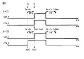
図7に、第2の実施形態において使用する第1のキャリアセンス閾値による第1のキャリアセンス及び第2のキャリアセンス閾値による第2のキャリアセンスによるアイドル/ビジーと判定時刻との関係図を示す。 FIG. 7 shows a relationship diagram between the idle time / busy by the first carrier sense by the first carrier sense threshold and the second carrier sense by the second carrier sense threshold used in the second embodiment and the determination time. .
第1の実施形態で説明した図2と同様、ケース1は、第1及び第2のキャリアセンスのビジー判定時刻が同時(或いは、ほぼ同時)の場合である。この場合は、受信処理で受信誤りが検出されたとしても、その原因が当該無線通信を行う一組の無線通信装置のみに関連する可能性が高い。一方、ケース2も、図2と同様、第2のキャリアセンス閾値のビジー判定時刻が第1のキャリアセンス閾値がビジー判定された判定時刻よりも前の場合である。この場合は、第1のキャリアセンス閾値では検出しないレベルであるが、第2のキャリアセンス閾値はビジー判定しており、応答信号の所要SINRを満たさないレベルの干渉が存在していると想定できる。このため、受信処理が誤る可能性が高く、誤った場合には、その原因が干渉による可能性が高い。
As in FIG. 2 described in the first embodiment,
なお、応答信号は、例えば、ACK応答でも良い。 The response signal may be an ACK response, for example.
第1の実施形態と異なり、無線通信装置は、第1のキャリアセンスがビジーになる前にデータフレーム送信を行った後に、送信処理から受信処理への切り替えを行う(図7中のTX→RX)。また、一般に、応答フレームは、例えばSIFSのような短い一定時間の経過後に送信するようにシステムで決まっている。これを応答フレームの期待時刻(図7中のTe)とすると、望ましくは、第1及び第2のキャリアセンス閾値を用いた判定時刻が応答フレームの期待時刻と一致する。 Unlike the first embodiment, the wireless communication apparatus performs switching from transmission processing to reception processing after performing data frame transmission before the first carrier sense becomes busy (TX → RX in FIG. 7). ). In general, the response frame is determined by the system to be transmitted after a short period of time such as SIFS. If this is the expected time of the response frame (Te in FIG. 7), the determination time using the first and second carrier sense thresholds preferably matches the expected time of the response frame.
図7では、応答フレームはSIFS後に送信されるため、ケース1のように、送信処理が終了してからSIFS後の期待時刻Teから第1及び第2のキャリアセンス閾値がビジーになる状況(すなわち、ビジー判定時刻Tcca2がビジー判定時刻Tcca1と同時(或いは、ほぼ同時)になる状況)が所望信号受信時の動きとなる。なお、受信が完了した場合には、例えば、Ackを返した後に、受信処理から送信処理への切り替えを行い(図7中のRX→TX)、IFS後に送信を開始し得る。
In FIG. 7, since the response frame is transmitted after SIFS, as in
一方、ケース2のように、送信処理が終了し、送受信切替を行い(図7中のTX→RX)、受信処理が起動してキャリアセンスをチェックすると、送信処理から受信処理への切替の直後(図7中のTs)から第2のキャリアセンス閾値を用いた結果がビジー判定されており、第1のキャリアセンスが応答フレームの期待時刻からビジー判定されている場合(すなわち、ビジー判定時刻Tcca2がビジー判定時刻Tcca1より前である場合)には、受信処理を行った応答フレームには誤りがある可能性が高い。
On the other hand, as in
なお、図7の例では、一定期間だけ判定を行った結果を想定して説明しているので、両キャリアセンスの結果が同時刻にアイドルになっているが、例えば常時判定を行う場合には、ケース2の第2のキャリアセンスの結果が、図7の例よりもより長い時間にわたってビジーを継続することも有り得る。
In addition, in the example of FIG. 7, the description is made on the assumption that the determination is made only for a certain period. Therefore, the results of both carrier senses are idle at the same time. The result of the second carrier sense in
次に、図8に、第2の実施形態において使用する両キャリアセンスのアイドル/ビジーと判定時刻との他の関係図を示す。 Next, FIG. 8 shows another relationship diagram between idle / busy of both carrier senses used in the second embodiment and the determination time.
図8では、図7とは異なり、応答フレームの期待時刻(図8中のTe)において、第1のキャリアセンス閾値による第1のキャリアセンスでのビジー判定結果が、ビジーと判定されない場合の例を示す。この場合は、応答フレーム受信がないため、そもそも送信フレームが誤った可能性が高いと判定するが、本実施形態では、その誤りの原因が干渉であるかどうかの判定を行う。 In FIG. 8, unlike FIG. 7, an example in which the busy determination result in the first carrier sense based on the first carrier sense threshold is not determined to be busy at the expected time of the response frame (Te in FIG. 8). Indicates. In this case, since there is no response frame reception, it is determined that there is a high possibility that the transmission frame is erroneous in the first place. In this embodiment, it is determined whether the cause of the error is interference.
ケース3では、第1のキャリアセンス閾値より感度点が低い第2のキャリアセンス閾値による第2のキャリアセンスでの判定は、応答フレームの期待時刻Teからビジーになる(判定時刻Tcca1が期待時刻Teになる)。一方、ケース4では、第2のキャリアセンスでの判定は、送信処理から受信処理への切替の直後(図8中のTs)からビジーになる(判定時刻Tcca2が応答フレームの期待時刻Teよりも前になる)。 In case 3, the determination by the second carrier sense based on the second carrier sense threshold whose sensitivity point is lower than the first carrier sense threshold is busy from the expected time Te of the response frame (the determination time Tcca1 is the expected time Te). become). On the other hand, in the case 4, the determination by the second carrier sense becomes busy immediately after switching from the transmission process to the reception process (Ts in FIG. 8) (the determination time Tcca2 is greater than the expected time Te of the response frame). Before).
このように、応答フレーム待ち状態で且つ応答フレーム受信時間の推定がタイマー等で可能な場合には、その時刻(期待時刻Te)を用いて、それよりも第2のキャリアセンスのビジー判定時刻が前の場合には、干渉と推定しても良い。 In this way, when the response frame reception state is possible with a timer or the like while waiting for a response frame, the busy determination time of the second carrier sense is set using that time (expected time Te). In the previous case, interference may be estimated.
次に、図9に、本実施形態に係る無線通信システムにおける無線通信装置100(図1中の無線通信装置1〜3)の構成例を示すためのブロック図を概略的に示す。
Next, FIG. 9 schematically shows a block diagram for illustrating a configuration example of the wireless communication device 100 (
図9の構成例は、基本的には図3の構成例と同様であるので、ここでは図3との相違点を中心に説明する。 The configuration example of FIG. 9 is basically the same as the configuration example of FIG. 3, and therefore, here, the description will focus on differences from FIG. 3.
図9の構成例では、図3の構成例に対して更にタイマー部45が設けられる。
In the configuration example of FIG. 9, a
本実施形態では、タイマー部45は、必要なタイマーを管理し、そして、応答フレームの期待時刻Teを計算するタイマーがタイムアウトした時点で、該タイマーのタイムアウトを干渉判定部44に通知する。干渉判定部44は、その通知されたタイミングを応答フレームの期待時刻として、これを用いて干渉の判定を行う。本実施形態では、フレーム送信後の応答フレーム待ち中であり、応答フレームの期待時刻を与えるSIFSを計るSIFSタイマーと、応答フレームの最大待ち時間を示すACKTO(Ack Timeout)を計るACKTOタイマーが起動している。
In the present embodiment, the
なお、図9では、タイマー部45はMAC処理部40の中に独立ブロックとして存在するが、その代わりに、図4のようにMAC処理部40内部に別途MAC制御部48が存在する場合には、MAC制御部の内部にタイマー部45が存在する構成でもよい。
In FIG. 9, the
また、第1の実施形態で説明したその他のバリエーションも、第2の実施形態にあてはまる。 The other variations described in the first embodiment also apply to the second embodiment.
次に、第2の実施形態における干渉判定部44の干渉判定処理について説明する。
Next, the interference determination process of the
図10に、第2の実施形態における干渉判定処理の一つの例を示す。 FIG. 10 shows an example of interference determination processing in the second embodiment.
ステップS31において、初期状態として、アイドル状態にある。 In step S31, the initial state is the idle state.
送信処理においてフレーム送信をすると(ステップS32)、応答フレームを受信待ちする状態に入り(ステップS33)、第2のキャリアセンス閾値でのビジー判定の有無を確認する。 When frame transmission is performed in the transmission process (step S32), a response frame is awaited to be received (step S33), and it is confirmed whether or not there is a busy determination at the second carrier sense threshold.
応答フレーム待ち期間(ACKTO)において、第2のキャリアセンス閾値でのビジー判定が無い場合(ステップS34でNo)、又は、第2のキャリアセンス閾値でのビジー判定が有っても、第1のキャリアセンス閾値でのビジー判定が無い場合(ステップS34でYes,S34でNo)、所定の時間後に(ステップS36)、次のフレームの送信を行う(ステップS32)。これが、適宜、繰り返される。 In the response frame waiting period (ACKTO), if there is no busy determination at the second carrier sense threshold (No in step S34), or even if there is a busy determination at the second carrier sense threshold, the first If there is no busy determination at the carrier sense threshold (Yes in step S34, No in S34), after a predetermined time (step S36), the next frame is transmitted (step S32). This is repeated as appropriate.
一方、第2のキャリアセンス閾値でのビジー判定が有り、更に、第1のキャリアセンス閾値でのビジー判定も有る場合(ステップS34でYes,S34でYes)、受信誤りの通知を受けたならば(ステップS37)、その判定時刻Tcca2と応答フレームの期待時刻Teとを比較し、判定時刻Tcca2が応答フレームの期待時刻よりも前の場合には、干渉が誤り要因になって送受信が上手くいかないと判定する、すなわち、干渉を回避するための処理を行うと判定する(ステップS39)。 On the other hand, if there is a busy determination at the second carrier sense threshold and there is also a busy determination at the first carrier sense threshold (Yes in step S34, Yes in S34), if a notification of reception error is received (Step S37), the determination time Tcca2 is compared with the expected time Te of the response frame. If the determination time Tcca2 is earlier than the expected time of the response frame, interference becomes an error factor and transmission / reception is not successful. That is, it is determined that processing for avoiding interference is performed (step S39).
なお、ステップS39において、実際には、干渉が誤り要因であるとの判定がなされなくても良く、ステップS38でYesの場合に、干渉を回避するための処理を行うとだけ判定されても良い。 In step S39, it may not be actually determined that interference is an error factor, and in the case of Yes in step S38, it may be determined only to perform processing for avoiding interference. .
これに対して、判定時刻Tcca2が応答期待時刻Teと同時(或いは、ほぼ同時)の場合には、干渉以外が誤り要因であると判定する、すなわち、干渉を回避するための処理を行わないと判定する(ステップS40)。 On the other hand, if the determination time Tcca2 is the same as (or almost the same as) the expected response time Te, it is determined that the error factor is other than interference, that is, the processing for avoiding the interference is not performed. Determine (step S40).
なお、ステップS40において、実際には、干渉以外が誤り要因であるとの判定がなされなくても良く、ステップS38でNoの場合に、干渉を回避するための処理を行わないとだけ判定されても良い。 It should be noted that in step S40, it may not actually be determined that an error factor other than interference is present, and in the case of No in step S38, it is determined only that the process for avoiding interference is not performed. Also good.
なお、干渉を回避するための処理を行わないと判定することは、干渉以外の原因等を回避又は解消等するための処理を行うと判定することを含んでも良い。 Note that determining that the process for avoiding the interference is not performed may include determining that the process for avoiding or eliminating the cause other than the interference is performed.
一方、受信誤りの通知を受けないならば(ステップS37でNo)、干渉があり得るが、問題はないと判定する(ステップS41)。 On the other hand, if the reception error notification is not received (No in step S37), it is determined that there may be interference but there is no problem (step S41).
本実施形態によれば、フレーム送信に対する応答信号受信待ち中の場合、タイマーから通知される応答信号がくると期待される時刻と、第2のキャリアセンスのビジー判定時刻を比較することで、第1のキャリアセンス結果にかかわらず、干渉の判定が可能となる。 According to the present embodiment, when waiting for response signal reception for frame transmission, the time when the response signal notified from the timer is expected to come and the busy determination time of the second carrier sense are compared. Interference can be determined regardless of the carrier sense result of 1.
このように本実施形態の無線通信装置によれば、近距離無線通信において送受信での誤り発生時に、干渉を回避するための処理を行うか否か判定することが可能になる(或いは、その原因が干渉にあるか否か判定することが可能になる)。 As described above, according to the wireless communication apparatus of this embodiment, it is possible to determine whether or not to perform processing for avoiding interference when an error occurs in transmission and reception in short-range wireless communication (or the cause thereof). It is possible to determine whether or not there is interference).
(第3の実施形態)
第1及び第2の実施形態では、フレーム受信時、フレーム送信時それぞれでの干渉判定を行う方法を示した。一方、第3の実施形態では、第1及び第2の実施形態で説明した干渉判定を行う干渉判定部44が常に干渉判定を行うのではなく、必要な時のみ起動する。第1及び第2の実施形態で説明したとおり、干渉に原因があるか否かの判定及び/又は干渉を回避するための処理を行うか否かの判定を行いたいのは、フレーム受信が誤った場合、又は、フレーム送信したにもかかわらず、応答フレームを応答フレームの期待時刻に受信しない若しくは受信した応答フレームの受信誤りがある若しくは所望のシーケンス番号の応答フレームでないといった場合である。
(Third embodiment)
In the first and second embodiments, the method of performing interference determination at the time of frame reception and frame transmission has been described. On the other hand, in the third embodiment, the
第3の実施形態では、通常は第1のキャリアセンス閾値のみを用いたキャリアセンスでビジー判定を行い、上記のような送受信誤りが発生するなどの問題があった場合にのみ、第2のキャリアセンス閾値をも用いて第1及び第2のキャリアセンスによるビジー判定を行う場合の処理について説明する。 In the third embodiment, normally, the busy detection is performed by carrier sense using only the first carrier sense threshold, and only when there is a problem such as occurrence of a transmission / reception error as described above, the second carrier A process in the case where the busy determination based on the first and second carrier senses is performed also using the sense threshold will be described.
次に、図11に、本実施形態に係る無線通信システムにおける無線通信装置100(図1中の無線通信装置1〜3)の構成例を示すためのブロック図を概略的に示す。
Next, FIG. 11 schematically shows a block diagram for illustrating a configuration example of the wireless communication device 100 (
図11の構成例は、基本的には図3又は図9の構成例と同様であるので、ここでは図3又は図9との相違点を中心に説明する。なお、図11の構成例では、図3の構成例に対して更にタイマー部45が設けられる。
The configuration example of FIG. 11 is basically the same as the configuration example of FIG. 3 or FIG. 9, and therefore, differences from FIG. 3 or FIG. 9 will be mainly described here. In the configuration example of FIG. 11, a
また、図9のようにタイマー部45がMAC処理部40の中に独立ブロックとして存在する代わりに、図4のようにMAC処理部40内部に別途MAC制御部48が存在する場合には、MAC制御部の内部にタイマー部45が存在する構成でもよい。
In addition, instead of the
また、第1及び第2の実施形態で説明したその他のバリエーションも、第3の実施形態にあてはまる。 The other variations described in the first and second embodiments also apply to the third embodiment.
さて、通常、干渉判定部44は、復調部32にCCA使用閾値として第1のキャリアセンス閾値を通知する。また、干渉判定部44は、受信部42からの受信誤り情報又はタイマー45からの応答フレームの期待時刻の通知のどちらかが入力されると、復調部32にCCA使用閾値として第1及び第2のキャリアセンス閾値を通知する。その後の処理は、第1及び第2の実施形態と同一であるため、ここでは省略する。
The
このように本実施形態では、干渉判定部44は、受信誤り情報又は応答フレーム待ち期間タイムアウト情報のいずれかをトリガに起動すれば良く、常に起動しておく必要がない。このため、無線通信装置の干渉判定にかかる消費電力を抑える効果が期待できる。例えば、第1の実施形態で説明した図6の干渉判定処理では、受信処理誤りの通知を用いて、最初の処理フローで分岐する構成であるため、本実施形態のように、受信処理誤りの通知をトリガに干渉判定部44を起動させ、受信処理誤りがある場合のみ、第1と第2のキャリアセンス閾値との比較処理を開始するようにしても良い。
As described above, in the present embodiment, the
本実施形態の他の例として、干渉判定部44の起動を送受信誤り発生時とする以外にも、例えば、2台の無線通信装置間で送受信開始前に行う接続処理中には、第1のキャリアセンス閾値のみ用いてキャリアセンスを行い、接続処理後のデータフレーム送受信中に、本実施形態の干渉判定部44を起動し、第1及び第2のキャリアセンス閾値を用いて両キャリアセンスを行うようにしても良い。すなわち、接続処理中においては、2台の無線通信装置間の位置合わせの影響等が大きいこと、或いは、複数の使用周波数がある場合、周波数を変更しつつサーチを行うため、干渉の影響を受けにくいことなどから、接続処理中にはこのような干渉判定を省く方法も可能であるからである。
As another example of the present embodiment, in addition to the activation of the
その他の例として、送受信誤り時に上記の干渉判定を行うことで、一度、他システムからの干渉があるとの判定或いは干渉を回避するための処理を行うとの判定がなされた場合には、その時の相手無線通信装置との接続が切れるまでは、常に第1及び第2の実施形態で説明したような第1及び第2のキャリアセンス閾値を用いた判定を行うことも考えられる。また、干渉が原因であるが、その後の処理でチャネル切替えを行わなかった場合に、そのような第1及び第2のキャリアセンス閾値を用いた判定を適用し、一方、チャネルを切替えた場合には、チャネル切替後は、第1のキャリアセンスのみを用いて送受信を開始しても良い。 As another example, when it is determined that there is interference from another system or a process for avoiding interference is performed once by performing the above interference determination at the time of transmission / reception error, Until the connection with the counterpart wireless communication device is disconnected, it is conceivable to always perform the determination using the first and second carrier sense thresholds as described in the first and second embodiments. In addition, when channel switching is not performed in subsequent processing due to interference, such determination using the first and second carrier sense thresholds is applied, while when channel switching is performed. After channel switching, transmission / reception may be started using only the first carrier sense.
このように本実施形態の無線通信装置によれば、近距離無線通信において送受信での誤り発生時に、干渉を回避するための処理を行うか否か判定することが可能になる(或いは、その原因が干渉にあるか否か判定することが可能になる)。 As described above, according to the wireless communication apparatus of this embodiment, it is possible to determine whether or not to perform processing for avoiding interference when an error occurs in transmission and reception in short-range wireless communication (or the cause thereof). It is possible to determine whether or not there is interference).
また、本実施形態によれば、干渉判定部を必要最小限に起動し、キャリアセンスも必要時のみ第2のキャリアセンスを用いるようにすることも可能であり、そのようにすることによって、干渉判定を行うことの処理負荷を低減しつつ、誤り時に即座にその原因を特定することが可能になる。 In addition, according to the present embodiment, it is possible to activate the interference determination unit to the minimum necessary, and to use the second carrier sense only when necessary for carrier sense. While reducing the processing load of performing the determination, it becomes possible to immediately identify the cause at the time of an error.
(第4の実施形態)
第1〜第3の実施形態では、第1及び第2のキャリアセンス閾値を用いて送受信誤りの原因が干渉によるものかの判定(及び/又は、干渉を回避するための処理を行うか否かの判定)を行う仕組みについて説明した。一方、第1〜第3の実施形態にて、干渉が誤りの原因であると特定した場合(或いは、干渉を回避するための処理を行うと判定された場合)の解決方法として、周波数チャネルを変更することがまず考えられるが、周波数チャネル数には限りがあり、複数の周波数チャネルで他システム又は自システムの他の無線通信装置同士のやりとりが行われている場合には、未使用の周波数チャネルを選択することができないことも考えられる。また、周波数チャネル毎の送受信特性が無線通信装置によっては異なる可能性もあり、その場合には、送受信特性の良い周波数チャネルをなるべく選択したいといったことが考えられる。本実施形態では、このように誤りの原因として干渉が考えられるが、同一周波数のまま送受信を行いたい場合の処理について考える。
(Fourth embodiment)
In the first to third embodiments, the first and second carrier sense thresholds are used to determine whether the cause of transmission / reception errors is due to interference (and / or whether to perform processing for avoiding interference). The mechanism for performing the determination of the above has been described. On the other hand, in the first to third embodiments, as a solution when the interference is specified as the cause of the error (or when it is determined that the processing for avoiding the interference is performed), the frequency channel is It is possible to change the frequency channel first, but the number of frequency channels is limited, and when there are multiple frequency channels that are exchanged between other systems or other wireless communication devices of the local system, unused frequencies It is also possible that the channel cannot be selected. In addition, there is a possibility that the transmission / reception characteristics for each frequency channel differ depending on the wireless communication device. In this case, it may be possible to select a frequency channel with good transmission / reception characteristics as much as possible. In this embodiment, interference can be considered as a cause of errors in this way, but processing in the case where it is desired to perform transmission / reception with the same frequency will be considered.
干渉が存在するときは、第1のキャリアセンス閾値による第1のキャリアセンスでキャリアセンスがアイドルになっても、送受信に誤りが発生する可能性が高いため、その中で無駄に送信を試し続けることは、無線通信装置の消費電力等を考慮しても得策でない。そのため、本実施形態では、干渉が存在すると判定されたときに、本来のキャリアセンス(第1のキャリアセンス)のためのキャリアセンス閾値として、第1のキャリアセンス閾値の代わりに、第2のキャリアセンス閾値と同じ値を設定し、第2のキャリアセンス閾値のみを用いて送受信を行うようにしても良い。または、送信時のみ、第1のキャリアセンス閾値の代わりに、第2のキャリアセンス閾値と同じ値を設定しても良い。 When there is interference, even if the carrier sense becomes idle in the first carrier sense based on the first carrier sense threshold, there is a high possibility that an error will occur in transmission / reception. This is not a good idea even if the power consumption of the wireless communication apparatus is taken into consideration. Therefore, in this embodiment, when it is determined that interference exists, the second carrier is used instead of the first carrier sense threshold as the carrier sense threshold for the original carrier sense (first carrier sense). The same value as the sense threshold may be set, and transmission / reception may be performed using only the second carrier sense threshold. Alternatively, only at the time of transmission, the same value as the second carrier sense threshold may be set instead of the first carrier sense threshold.
また、前述のように、ここで想定する近距離システムでは、近距離の無線通信装置同士のみが接続処理を行うように第1のキャリアセンスの感度点を高く設定していることを考えると、接続処理中のキャリアセンス閾値としては、第1のキャリアセンス閾値を用いることが望ましい。しかし、接続処理後の接続中のデータフレーム送受信時には、第2のキャリアセンス閾値を用いても、上記の問題は生じない。そのため、接続処理後で、干渉が存在すると判定されたときのみ、第2のキャリアセンス閾値と同じ値を、通常の第1のキャリアセンス閾値として扱っても良い。 Further, as described above, in the short-range system assumed here, considering that the sensitivity point of the first carrier sense is set high so that only short-range wireless communication devices perform connection processing, It is desirable to use the first carrier sense threshold as the carrier sense threshold during the connection process. However, the above-described problem does not occur even when the second carrier sense threshold is used during transmission / reception of a data frame during connection after connection processing. Therefore, the same value as the second carrier sense threshold value may be treated as the normal first carrier sense threshold value only when it is determined that interference exists after the connection processing.
このように第1〜第3の実施形態での判定により、干渉が存在しそれが誤り原因となっている可能性が高い場合で、周波数チャネルの変更を行わない場合には、第2のキャリアセンス閾値を用いて少なくとも送信判定を行うことで、送信しても干渉の影響により誤りが発生する可能性が高い場合に、無駄に送信処理を行うことを避けることが可能となる。 As described above, when the determination in the first to third embodiments shows that there is a high possibility that interference exists and this is the cause of the error, and the frequency channel is not changed, the second carrier is used. By performing at least transmission determination using the sense threshold, it is possible to avoid performing transmission processing wastefully when there is a high possibility that an error will occur due to the influence of interference even if transmission is performed.
このように本実施形態の無線通信装置によれば、近距離無線通信において送受信での誤り発生時に、干渉を回避するための処理を行うか否か判定することが可能になる(或いは、その原因が干渉にあるか否か判定することが可能になる)。 As described above, according to the wireless communication apparatus of this embodiment, it is possible to determine whether or not to perform processing for avoiding interference when an error occurs in transmission and reception in short-range wireless communication (or the cause thereof). It is possible to determine whether or not there is interference).
(第5の実施形態)
第1〜第4の実施形態では、第1及び第2のキャリアセンス閾値の使用方法の説明を行った。第5の実施形態では、第2のキャリアセンス閾値の決め方について説明する。
(Fifth embodiment)
In the first to fourth embodiments, the method of using the first and second carrier sense thresholds has been described. In the fifth embodiment, a method for determining the second carrier sense threshold will be described.
図12に、自システムの無線通信装置間距離を決めた場合の信号対雑音干渉電力比(SINR)及び受信信号強度(RSSI)の特性の例を示す。横軸を、送受信無線通信装置と他システムの無線通信装置との距離dとする。図12のようなSINR及びRSSIの特性は、自システム及び他システムの送信電力と、自無線通信装置のアンテナゲイン等の設定が分かれば、計算可能である。 FIG. 12 shows an example of characteristics of the signal-to-noise interference power ratio (SINR) and the received signal strength (RSSI) when the distance between the wireless communication devices of the own system is determined. The horizontal axis is the distance d between the transmission / reception wireless communication device and the wireless communication device of another system. The SINR and RSSI characteristics as shown in FIG. 12 can be calculated if the transmission power of the own system and other systems and the settings of the antenna gain of the own wireless communication device are known.
なお、RSSIが第1のキャリアセンス閾値以上になる領域が、ビジー判定となる領域であり、RSSIが第1のキャリアセンス閾値未満になる領域が、アイドル判定となる領域である。また、SINRが所要SINR(所要信号対雑音干渉電力比)以上になる領域が、所要SINRを満たす領域であり、SINRが所要SINR未満になる領域が、所要SINRを満たさない領域である。 In addition, the area | region where RSSI becomes more than a 1st carrier sense threshold value is an area | region used as busy determination, and the area | region where RSSI is less than a 1st carrier sense threshold value is an area | region used as idle determination. Further, a region where the SINR is equal to or greater than the required SINR (required signal-to-noise interference power ratio) is a region where the required SINR is satisfied, and a region where the SINR is less than the required SINR is a region where the required SINR is not satisfied.
さて、上記の設定条件を用いて計算したSINR及びRSSIの特性図に、システムで決定される第1のキャリアセンス閾値(図12ではy)及び所要SINR(図12ではx)をあてはめると、RSSIがアイドルであるが、所要SINRを満たさない範囲(図12中の1000)が生じ、キャリアセンス閾値をさげると、当該範囲を低減又は除去できることが、図12からわかる。そこで、第2のキャリアセンス閾値は、例えば、図12に示すように、上記範囲が無くなる程度に、第1のキャリアセンス閾値の感度点を下げた設定とする。上記説明のように、図12に示す特性図はシステムの設定条件のみで決まるため、無線通信装置として予め計算可能であり、接続の度の再計算及び接続中の再計算等を必要としない。 When the first carrier sense threshold (y in FIG. 12) and the required SINR (x in FIG. 12) determined by the system are applied to the SINR and RSSI characteristic diagrams calculated using the above setting conditions, RSSI As can be seen from FIG. 12, a range (1000 in FIG. 12) that is idle but does not satisfy the required SINR occurs, and that range can be reduced or eliminated by reducing the carrier sense threshold. Therefore, for example, as shown in FIG. 12, the second carrier sense threshold is set such that the sensitivity point of the first carrier sense threshold is lowered to such an extent that the above range disappears. As described above, since the characteristic diagram shown in FIG. 12 is determined only by the setting conditions of the system, it can be calculated in advance as a wireless communication apparatus, and does not require recalculation of the degree of connection, recalculation during connection, and the like.
このように予めSINR及びRSSIの特性から、RSSIがアイドルであるが、所要SINRを満たさない範囲を無くすように、第2のキャリアセンス閾値を設定し、第1〜第4の実施形態のように、第2のキャリアセンス閾値を用いることで、誤り原因の判定或いは干渉を回避するための処理を行うか否かの判定等が行える。 Thus, from the characteristics of SINR and RSSI, the second carrier sense threshold is set so as to eliminate the range where RSSI is idle but does not satisfy the required SINR, as in the first to fourth embodiments. By using the second carrier sense threshold, it is possible to determine the cause of error or whether or not to perform processing for avoiding interference.
本実施形態によれば、所要信号対雑音干渉電力比以下の信号対雑音干渉電力比の時点で、必ずキャリアセンスがビジーになるように第2のキャリアセンス閾値を決めることで、少なくとも第2のキャリアセンス閾値を用いれば、キャリアセンスアイドルであるが、干渉の影響で送受信が誤る状況の原因を特定すること、そして、干渉を回避するための処理を行うか否かを判定することが可能になる。 According to the present embodiment, at least the second carrier sense threshold is determined by determining the second carrier sense threshold so that the carrier sense is always busy at the time of the signal-to-noise interference power ratio equal to or lower than the required signal-to-noise interference power ratio. By using the carrier sense threshold, it is possible to identify the cause of the situation where the carrier sense idle, but transmission / reception is erroneous due to the influence of interference, and whether to perform processing for avoiding the interference. Become.
以下では、これまでに説明した実施形態に対するバリエーションについて説明する。以下の任意の一つの実施形態又は以下の実施形態を任意に組み合わせたものは、これまでに説明した任意の実施形態と組み合わせて実施することが可能である。 Below, the variation with respect to embodiment described so far is demonstrated. Any one of the following embodiments or any combination of the following embodiments can be implemented in combination with any of the embodiments described above.
(第6の実施形態)
第6の実施形態では、これまでの実施形態の無線通信装置の構成(例えば、図3、図4、図9又は図11の無線通信装置100参照)に加えて、バッファを備える構成について説明する。バッファは、送信部41及び受信部42それぞれと接続される。バッファは、上位層処理部(図示せず)の内部に存在しても良いし、送信部41/受信部42と上位層処理部との間に存在しても良いし、それらの組み合わせであっても良い。このように、バッファを無線通信装置に含める構成とすることによって、送受信データをバッファに保持することが可能となり、再送処理及び/又は外部出力処理を容易に行うことが可能となる。
(Sixth embodiment)
In the sixth embodiment, a configuration including a buffer in addition to the configuration of the wireless communication device of the previous embodiments (for example, see the
(第7の実施形態)
第7の実施形態では、第6の実施形態の無線通信装置の構成に加えて、バス、プロセッサ部、外部インターフェースを備える構成について説明する。バスは第6の実施形態で示すバッファに接続され、プロセッサ部及び外部インターフェース部はそれぞれバスに接続される(すなわち、プロセッサ部及び外部インターフェース部はいずれもバスを介してバッファに接続される)。プロセッサ部では、ファームウエアが動作しても良い。また、これらのプロセッサ部、バス及び外部インターフェースは、上位層処理部(図示せず)に存在しても良いし、上位層処理部とは独立して存在しても良いし、それらの組み合わせであっても良い。このように、ファームウエアを無線通信装置に含める構成とすることにより、ファームウエアの書き換えによって無線通信装置の機能の変更を容易に行うことが可能となる。
(Seventh embodiment)
In the seventh embodiment, a configuration including a bus, a processor unit, and an external interface in addition to the configuration of the wireless communication apparatus of the sixth embodiment will be described. The bus is connected to the buffer shown in the sixth embodiment, and the processor unit and the external interface unit are each connected to the bus (that is, both the processor unit and the external interface unit are connected to the buffer via the bus). Firmware may operate in the processor unit. The processor unit, bus, and external interface may exist in an upper layer processing unit (not shown), may exist independently of the upper layer processing unit, or a combination thereof. There may be. As described above, by configuring the firmware to be included in the wireless communication device, it is possible to easily change the function of the wireless communication device by rewriting the firmware.
(第8の実施形態)
第8の実施形態では、第7の実施形態の無線通信装置の構成に加えて、動画像圧縮/伸長部を備える構成について説明する。動画像圧縮/伸長部は、第7の実施形態で示したバスに接続される。このように、動画像圧縮/伸長部を無線通信装置に備える構成とすることによって、圧縮した動画像の伝送と受信した圧縮動画像の伸長とを容易に行うことが可能となる。
(Eighth embodiment)
In the eighth embodiment, a configuration including a moving image compression / decompression unit in addition to the configuration of the wireless communication apparatus of the seventh embodiment will be described. The moving image compression / decompression unit is connected to the bus shown in the seventh embodiment. As described above, by providing the wireless communication device with the moving image compression / decompression unit, it is possible to easily transmit the compressed moving image and expand the received compressed moving image.
(第9の実施形態)
第9の実施形態では、これまでの実施形態の無線通信装置の構成に加えて、クロック生成部を備える構成について説明する。クロック生成部は、無線通信装置の無線送受信部に接続される。なお、無線送受信部は、例えば、図3、図4、図9又は図11における、無線部20と変復調部30とMAC処理部40の全体を含む部分に相当する。また、クロック生成部により生成されるクロックは、出力端子を介して外部に出力される。このように、無線通信装置の内部で生成されたクロックを外部に出力し、外部に出力されたクロックによってホスト側を動作させることにより、ホスト側と無線通信装置側とを同期させて動作させることが可能となる。
(Ninth embodiment)
In the ninth embodiment, a configuration including a clock generation unit will be described in addition to the configuration of the wireless communication apparatus of the previous embodiments. The clock generation unit is connected to the wireless transmission / reception unit of the wireless communication device. Note that the wireless transmission / reception unit corresponds to, for example, a part including the
(第10の実施形態)
第10の実施形態では、これまでの実施形態の無線通信装置の構成に加えて、電源部、電源制御部及び無線電力給電部を備える構成について説明する。電源部、電源制御部及び無線電力給電部は、無線通信装置の無線送受信部に接続される。例として、図13に、電源部、電源制御部及び無線電力給電部を図3の無線通信装置100に追加した場合の構成例を示す。図13に例示された無線通信装置1300において、電源部1301、電源制御部1302及び無線電力給電部1303は、いずれも無線送受信部60に接続されている。このように、電源を無線通信装置に備える構成とすることにより、電源を制御した低消費電力化動作が可能となる。
(Tenth embodiment)
In the tenth embodiment, a configuration including a power supply unit, a power supply control unit, and a wireless power supply unit will be described in addition to the configuration of the wireless communication apparatus of the previous embodiments. The power supply unit, the power supply control unit, and the wireless power supply unit are connected to a wireless transmission / reception unit of the wireless communication device. As an example, FIG. 13 shows a configuration example when a power supply unit, a power supply control unit, and a wireless power feeding unit are added to the
(第11の実施形態)
第11の実施形態では、第10の実施形態の無線通信装置の構成に加えて、NFC(Near Field Communications)送受信部を備える構成を示す。NFC送受信部は、無線通信装置の電源制御部及びMAC処理部に接続される。例えば、図13の無線通信装置1100の場合には、NFC送受信部が、図13の電源制御部1302及び無線送受信部60内のMAC処理部40に接続される。NFC送受信部は、上位層処理部50の内部に存在しても良いし、上位層処理部50とは独立して存在しても良い。このように、NFC送受信部を無線通信装置に備える構成とすることにより、容易に認証処理を行うことが可能となるとともに、NFC送受信部をトリガとして電源制御を行うことによって、待受け時の低消費電力化を図ることが可能となる。
(Eleventh embodiment)
In the eleventh embodiment, in addition to the configuration of the wireless communication apparatus of the tenth embodiment, a configuration including an NFC (Near Field Communications) transmission / reception unit is shown. The NFC transmission / reception unit is connected to the power supply control unit and the MAC processing unit of the wireless communication apparatus. For example, in the case of the wireless communication apparatus 1100 in FIG. 13, the NFC transmission / reception unit is connected to the
(第12の実施形態)
第12の実施形態では、第10又は第11の実施形態の無線通信装置の構成に加えて、SIMカードを備える構成を示す。SIMカードは、MAC処理部(40)と接続される。SIMカードは、上位層処理部50の内部に存在しても良いし、上位層処理部50とは独立して存在しても良い。このように、SIMカードを無線通信装置に備える構成とすることにより、容易に認証処理を行うことが可能となる。
(Twelfth embodiment)
In the twelfth embodiment, a configuration including a SIM card is shown in addition to the configuration of the wireless communication apparatus of the tenth or eleventh embodiment. The SIM card is connected to the MAC processing unit (40). The SIM card may exist inside the upper
(第13の実施形態)
第13の実施形態では、これまでの実施形態の無線通信装置の構成に加えて、LED部を備える構成について説明する。LED部は、無線通信装置の無線送受信部に接続される。このように、LEDを無線通信装置に備える構成とすることにより、無線通信装置の動作状態をユーザに容易に通知することが可能となる。
(13th Embodiment)
In the thirteenth embodiment, a configuration including an LED unit will be described in addition to the configuration of the wireless communication apparatus of the previous embodiments. The LED unit is connected to a wireless transmission / reception unit of the wireless communication device. As described above, by providing the wireless communication device with the LED, it is possible to easily notify the user of the operation state of the wireless communication device.
(第14の実施形態)
第14の実施形態では、これまでの実施形態の無線通信装置の構成に加えて、バイブレータ部を備える構成について説明する。バイブレータ部は、無線通信装置の無線送受信部に接続される。このように、バイブレータを無線通信装置に備える構成とすることにより、無線通信装置の動作状態をユーザに容易に通知することが可能となる。
(Fourteenth embodiment)
In the fourteenth embodiment, a configuration including a vibrator unit will be described in addition to the configuration of the wireless communication apparatus of the previous embodiments. The vibrator unit is connected to a wireless transmission / reception unit of the wireless communication device. As described above, the configuration in which the vibrator is provided in the wireless communication device makes it possible to easily notify the user of the operation state of the wireless communication device.
(第15の実施形態)
第15の実施形態は、これまでの実施形態の無線通信装置の構成に加えて、アンテナ10が無線通信装置について説明する。アンテナ10を無線通信装置1に含める構成とすることによって、アンテナまで含めた一つの装置として無線通信装置を構成することが可能となり、実装面積を少なく抑えることが可能となる。また、例えば図3、図4、図9、図11又は図13でも示しているが、アンテナ10を送信処理と受信処理で共用している。このように、一つのアンテナを送信処理及び受信処理で共用することによって、無線通信装置を小型化することが可能となる。
(Fifteenth embodiment)
In the fifteenth embodiment, in addition to the configuration of the wireless communication device of the previous embodiments, the
(第16の実施形態)
第16の実施形態では、これまでの実施形態の無線通信装置の構成に加えて、無線LAN部及び無線切替部を備える構成について説明する。例として、図14に、無線LAN部及び無線切替部を図9の無線通信装置100に追加した場合の構成例を示す。図14に例示された無線通信装置1400において、無線LAN部141は、上位層処理部50及び無線切替部142に接続され、無線切替部142は、無線送受信部60、上位層処理部50及び無線LAN部141に接続される。このように、無線LAN機能を無線通信装置に備える構成とすることによって、状況に応じて無線LANによる通信と無線送受信部60による通信とを切替えることが可能となる。特に前述したようにミリ波帯では複数チャネルの使用が可能であるが、例えば、当該無線通信システムにおいて、どのチャネルでも他の無線通信システムとの干渉が大きく、所望の送受信ができないような場合などには、無線LANによる通信に切り替えても良い。ここで、切り替える無線LANは、当該無線通信システムと異なる周波数帯域を使用する無線通信システム(例えば、IEEE 802.11a,b,g等)でも良いし、当該無線通信システムと同一の周波数帯域を使用する無線通信システム(例えば、802.11ad等)でも良い。また、無線LAN部にも独自の送受信アンテナがあっても良く、また、当該無線通信システムと同一の周波数帯域を使用する無線LANの場合にはアンテナを当該無線通信システムと共有しても良い。
(Sixteenth embodiment)
In the sixteenth embodiment, a configuration including a wireless LAN unit and a wireless switching unit will be described in addition to the configuration of the wireless communication apparatus of the previous embodiments. As an example, FIG. 14 shows a configuration example when a wireless LAN unit and a wireless switching unit are added to the
(第17の実施形態)
第17の実施形態では、第16の実施形態の無線通信装置の構成に加えて、スイッチ(SW)を備える構成について説明する。スイッチは、無線送受信部、無線LAN部及び無線切替部にそれぞれ接続される。例えば、図14の無線通信装置1400の場合には、スイッチは、図14の無線送受信部60、無線LAN部141及び無線切替部142にそれぞれ接続される。このように、スイッチを無線通信装置に備える構成とすることによって、アンテナを共用しながら状況に応じて無線LANによる通信と無線送受信部60による通信とを切替えることが可能となる。
(Seventeenth embodiment)
In the seventeenth embodiment, a configuration including a switch (SW) in addition to the configuration of the wireless communication apparatus of the sixteenth embodiment will be described. The switch is connected to the wireless transmission / reception unit, the wireless LAN unit, and the wireless switching unit. For example, in the case of the
以上述べた少なくともひとつの実施形態の無線通信装置によれば、近距離無線通信において送受信での誤り発生時に、干渉を回避するための処理を行うか否か判定することが可能になる。 According to the wireless communication device of at least one embodiment described above, it is possible to determine whether or not to perform processing for avoiding interference when an error occurs in transmission and reception in short-range wireless communication.
本発明のいくつかの実施形態を説明したが、これらの実施形態は、例として提示したものであり、発明の範囲を限定することは意図していない。これら新規な実施形態は、その他の様々な形態で実施されることが可能であり、発明の要旨を逸脱しない範囲で、種々の省略、置き換え、変更を行うことができる。これら実施形態やその変形は、発明の範囲や要旨に含まれるとともに、特許請求の範囲に記載された発明とその均等の範囲に含まれる。 Although several embodiments of the present invention have been described, these embodiments are presented by way of example and are not intended to limit the scope of the invention. These novel embodiments can be implemented in various other forms, and various omissions, replacements, and changes can be made without departing from the scope of the invention. These embodiments and modifications thereof are included in the scope and gist of the invention, and are included in the invention described in the claims and the equivalents thereof.
1〜3,100,1300,1400…無線通信装置、10…アンテナ、20…無線部、30…変復調部、31…変調部、32…復調部、40…MAC処理部、41…送信部、42…受信部、43…通信状況判定部、44…干渉判定部、45…タイマー部、48…MAC制御部、50…上位層処理部、60…無線送受信部、1301…電源部、1302…電源制御部、1303…無線電力給電部、141…無線LAN部、142…無線切替部。 1 to 3, 100, 1300, 1400 ... wireless communication device, 10 ... antenna, 20 ... wireless unit, 30 ... modulator / demodulator, 31 ... modulator, 32 ... demodulator, 40 ... MAC processor, 41 ... transmitter, 42 ... Receiving unit, 43 ... Communication status determining unit, 44 ... Interference determining unit, 45 ... Timer unit, 48 ... MAC control unit, 50 ... Upper layer processing unit, 60 ... Radio transceiver unit, 1301 ... Power supply unit, 1302 ... Power control , 1303... Wireless power supply unit, 141... Wireless LAN unit, 142.
Claims (10)
少なくとも、前記第2のキャリアセンス閾値を用いてビジーと判定され、且つ、前記第2時刻が、前記第1時刻以前の基準時刻より前である場合に、干渉を回避するための処理を行うと判定する第2の判定部とを含む無線通信装置。 The first carrier sense threshold is used to determine whether or not busy, the first carrier sense threshold is used to identify the first time that is determined to be busy, and the value is greater than the first carrier sense threshold. A first determination unit that determines whether busy using a small second carrier sense threshold and identifies a second time determined busy using the second carrier sense threshold;
When at least the second carrier sense threshold is used to determine busy, and the second time is before a reference time before the first time, a process for avoiding interference is performed. A wireless communication device including a second determination unit for determination.
前記第2の判定部は、更に前記誤り情報の通知を受け、受信フレームの誤りが有る場合であって、更に、前記第2のキャリアセンス閾値を用いてビジーと判定され、且つ、前記第2時刻が、前記基準時刻より前である場合に、干渉を回避するための処理を行うと判定することを特徴とする請求項1に記載の無線通信装置。 A reception unit for receiving a frame, determining whether there is an error in the received frame, and notifying error information;
The second determination unit is further notified of the error information, and when there is an error in a received frame, is further determined to be busy using the second carrier sense threshold, and the second The wireless communication apparatus according to claim 1, wherein when the time is before the reference time, it is determined that processing for avoiding interference is performed.
送受信のために使用する少なくとも一つのタイマーを管理し、前記送信部による前記フレームの送信処理が終了したときに、応答フレーム受信を期待するタイマーを起動し、該タイマーのタイムアウト時に、タイムアウトを前記第1の判定部に通知するタイマー部とを更に備え、
前記第2の判定部は、前記第2時刻が、前記タイマー部からタイムアウトが通知された時刻より前である場合に、干渉が誤りを回避するための処理を行うと判定することを特徴とする請求項1ないし3のいずれか1項に記載の無線通信装置。 A transmission unit for transmitting a frame;
At least one timer used for transmission / reception is managed, and when the transmission processing of the frame by the transmission unit is completed, a timer that expects reception of a response frame is started. A timer unit for notifying the determination unit 1;
The second determination unit determines that interference performs a process for avoiding an error when the second time is before the time when a timeout is notified from the timer unit. The wireless communication apparatus according to any one of claims 1 to 3.
MAC処理を行うMAC処理部とを更に備え、
前記第1の判定部は、前記MAC処理部内に設けられ、
前記第2の判定部は、前記復調部内又は前記MAC処理部内に設けられる請求項1ないし6のいずれか1項に記載の無線通信装置。 A demodulator for demodulating;
A MAC processing unit that performs MAC processing;
The first determination unit is provided in the MAC processing unit,
The wireless communication apparatus according to claim 1, wherein the second determination unit is provided in the demodulation unit or the MAC processing unit.
第1のキャリアセンス閾値を用いてビジーか否かを判定し、
前記第1のキャリアセンス閾値を用いてビジーと判定された第1時刻を特定し、
前記第1のキャリアセンス閾値よりも値が小さい第2のキャリアセンス閾値を用いてビジーか否かを判定し、
前記第2のキャリアセンス閾値を用いてビジーと判定された第2時刻を特定し、
少なくとも、前記第2のキャリアセンス閾値を用いてビジーと判定され、且つ、前記第2時刻が、前記第1時刻以前の基準時刻より前である場合に、干渉を回避するための処理を行うと判定することを特徴とする干渉検出方法。 In an interference detection method for a wireless communication device,
Using the first carrier sense threshold to determine whether busy,
Identifying a first time determined to be busy using the first carrier sense threshold;
Determining whether it is busy using a second carrier sense threshold value that is smaller than the first carrier sense threshold value;
Identifying a second time determined to be busy using the second carrier sense threshold;
When at least the second carrier sense threshold is used to determine busy, and the second time is before a reference time before the first time, a process for avoiding interference is performed. An interference detection method characterized by determining.
Priority Applications (4)
| Application Number | Priority Date | Filing Date | Title |
|---|---|---|---|
| JP2012044369A JP5762997B2 (en) | 2012-02-29 | 2012-02-29 | Wireless communication apparatus and interference detection method |
| US13/727,406 US9066245B2 (en) | 2012-02-29 | 2012-12-26 | Wireless communication apparatus and interference detection method |
| US14/716,428 US9553688B2 (en) | 2012-02-29 | 2015-05-19 | Wireless communication apparatus and interference detection method |
| US15/366,521 US10085285B2 (en) | 2012-02-29 | 2016-12-01 | Wireless communication apparatus and interference detection method |
Applications Claiming Priority (1)
| Application Number | Priority Date | Filing Date | Title |
|---|---|---|---|
| JP2012044369A JP5762997B2 (en) | 2012-02-29 | 2012-02-29 | Wireless communication apparatus and interference detection method |
Related Child Applications (1)
| Application Number | Title | Priority Date | Filing Date |
|---|---|---|---|
| JP2015110709A Division JP2015149790A (en) | 2015-05-29 | 2015-05-29 | Radio communication device and interference detection method |
Publications (2)
| Publication Number | Publication Date |
|---|---|
| JP2013183221A true JP2013183221A (en) | 2013-09-12 |
| JP5762997B2 JP5762997B2 (en) | 2015-08-12 |
Family
ID=49002760
Family Applications (1)
| Application Number | Title | Priority Date | Filing Date |
|---|---|---|---|
| JP2012044369A Active JP5762997B2 (en) | 2012-02-29 | 2012-02-29 | Wireless communication apparatus and interference detection method |
Country Status (2)
| Country | Link |
|---|---|
| US (3) | US9066245B2 (en) |
| JP (1) | JP5762997B2 (en) |
Cited By (5)
| Publication number | Priority date | Publication date | Assignee | Title |
|---|---|---|---|---|
| JP2015149542A (en) * | 2014-02-05 | 2015-08-20 | 株式会社Nttドコモ | Mobile communication system and mobile station apparatus |
| JP2016201849A (en) * | 2016-09-05 | 2016-12-01 | 株式会社東芝 | Radio communication device and interference detection method |
| WO2017154380A1 (en) * | 2016-03-08 | 2017-09-14 | ソニー株式会社 | Wireless communication device and wireless communication method |
| US10085285B2 (en) | 2012-02-29 | 2018-09-25 | Kabushiki Kaisha Toshiba | Wireless communication apparatus and interference detection method |
| WO2018220962A1 (en) | 2017-06-02 | 2018-12-06 | ソニー株式会社 | Communication device and communication system |
Families Citing this family (14)
| Publication number | Priority date | Publication date | Assignee | Title |
|---|---|---|---|---|
| US10231065B2 (en) * | 2012-12-28 | 2019-03-12 | Gn Hearing A/S | Spectacle hearing device system |
| US9288709B2 (en) * | 2013-02-10 | 2016-03-15 | Qualcomm Incorporated | Adjustable carrier sense threshold for wireless broadcast |
| US9220115B2 (en) * | 2013-10-23 | 2015-12-22 | Qualcomm Incorporated | Techniques for channel access in asynchronous unlicensed radio frequency spectrum band deployments |
| CN103701508B (en) * | 2013-12-31 | 2016-08-31 | 深圳市汇顶科技股份有限公司 | The near field communication method of a kind of electronic equipment and system |
| JP2015220613A (en) * | 2014-05-16 | 2015-12-07 | 株式会社東芝 | Radio reception device |
| US9571257B2 (en) * | 2014-08-19 | 2017-02-14 | Newracom, Inc. | System and method for wireless channel assessment |
| US9698918B2 (en) | 2014-09-12 | 2017-07-04 | Newracom, Inc. | Distributed adaptive CCA mechanisms |
| WO2016106655A1 (en) * | 2014-12-31 | 2016-07-07 | 华为技术有限公司 | Data transmission method, apparatus and device |
| EP3253167B1 (en) * | 2015-01-26 | 2021-09-01 | Sharp Kabushiki Kaisha | Terminal device and base station device |
| US11470638B2 (en) * | 2015-03-11 | 2022-10-11 | Sharp Kabushiki Kaisha | Terminal apparatus and communication method |
| US9762368B2 (en) * | 2015-04-10 | 2017-09-12 | Motorola Mobility Llc | In-device coexistence with other technologies in LTE license assisted access operation |
| CN106686746A (en) * | 2015-11-10 | 2017-05-17 | 中兴通讯股份有限公司 | Channel detection method and channel detection device |
| US9929779B2 (en) * | 2015-12-01 | 2018-03-27 | Maxim Integrated Products, Inc. | Power adaptive dual mode card emulation system for NFC and RFID application |
| WO2020111115A1 (en) * | 2018-11-28 | 2020-06-04 | 日本電気株式会社 | Interference detection system, interference detection device, interference detection method, and interference detection program |
Citations (3)
| Publication number | Priority date | Publication date | Assignee | Title |
|---|---|---|---|---|
| JPH08331045A (en) * | 1995-06-05 | 1996-12-13 | Nippon Telegr & Teleph Corp <Ntt> | Method for discriminating interference and collision of radio packet |
| JPH11103481A (en) * | 1997-09-26 | 1999-04-13 | Taiyo Yuden Co Ltd | Device for deciding existence of receiving signal |
| JP2007134905A (en) * | 2005-11-09 | 2007-05-31 | Toshiba Corp | Wireless communication device and wireless communication method |
Family Cites Families (11)
| Publication number | Priority date | Publication date | Assignee | Title |
|---|---|---|---|---|
| US6067291A (en) | 1997-09-23 | 2000-05-23 | Lucent Technologies Inc. | Wireless local area network with enhanced carrier sense provision |
| JP3432475B2 (en) | 2000-02-23 | 2003-08-04 | 日本電信電話株式会社 | Transmission suspension period control circuit in digital wireless communication system |
| US7366144B2 (en) | 2002-03-25 | 2008-04-29 | Agere Systems Inc. | Method of dynamically setting at least one threshold at an access point in a wireless local area network and the access point |
| JP4220435B2 (en) * | 2004-05-28 | 2009-02-04 | 株式会社東芝 | Wireless communication system and wireless terminal |
| JP5044320B2 (en) | 2006-07-27 | 2012-10-10 | パナソニック株式会社 | Wireless communication apparatus and wireless LAN system |
| WO2008072301A1 (en) * | 2006-12-11 | 2008-06-19 | Mitsubishi Electric Corporation | Data communication device, communication method, and program |
| JP4284354B2 (en) * | 2006-12-26 | 2009-06-24 | 株式会社東芝 | Wireless communication device |
| JP5155697B2 (en) * | 2008-03-05 | 2013-03-06 | 株式会社東芝 | Wireless communication device |
| JP5106291B2 (en) * | 2008-07-24 | 2012-12-26 | 株式会社東芝 | Communication device |
| JP5193823B2 (en) * | 2008-11-20 | 2013-05-08 | 三洋電機株式会社 | Notification method and radio apparatus |
| JP5762997B2 (en) | 2012-02-29 | 2015-08-12 | 株式会社東芝 | Wireless communication apparatus and interference detection method |
-
2012
- 2012-02-29 JP JP2012044369A patent/JP5762997B2/en active Active
- 2012-12-26 US US13/727,406 patent/US9066245B2/en active Active
-
2015
- 2015-05-19 US US14/716,428 patent/US9553688B2/en active Active
-
2016
- 2016-12-01 US US15/366,521 patent/US10085285B2/en active Active
Patent Citations (3)
| Publication number | Priority date | Publication date | Assignee | Title |
|---|---|---|---|---|
| JPH08331045A (en) * | 1995-06-05 | 1996-12-13 | Nippon Telegr & Teleph Corp <Ntt> | Method for discriminating interference and collision of radio packet |
| JPH11103481A (en) * | 1997-09-26 | 1999-04-13 | Taiyo Yuden Co Ltd | Device for deciding existence of receiving signal |
| JP2007134905A (en) * | 2005-11-09 | 2007-05-31 | Toshiba Corp | Wireless communication device and wireless communication method |
Cited By (7)
| Publication number | Priority date | Publication date | Assignee | Title |
|---|---|---|---|---|
| US10085285B2 (en) | 2012-02-29 | 2018-09-25 | Kabushiki Kaisha Toshiba | Wireless communication apparatus and interference detection method |
| JP2015149542A (en) * | 2014-02-05 | 2015-08-20 | 株式会社Nttドコモ | Mobile communication system and mobile station apparatus |
| WO2017154380A1 (en) * | 2016-03-08 | 2017-09-14 | ソニー株式会社 | Wireless communication device and wireless communication method |
| JPWO2017154380A1 (en) * | 2016-03-08 | 2019-01-10 | ソニー株式会社 | Wireless communication apparatus and wireless communication method |
| US11219030B2 (en) | 2016-03-08 | 2022-01-04 | Sony Corporation | Wireless communication device and wireless communication method |
| JP2016201849A (en) * | 2016-09-05 | 2016-12-01 | 株式会社東芝 | Radio communication device and interference detection method |
| WO2018220962A1 (en) | 2017-06-02 | 2018-12-06 | ソニー株式会社 | Communication device and communication system |
Also Published As
| Publication number | Publication date |
|---|---|
| US20170086227A1 (en) | 2017-03-23 |
| US9066245B2 (en) | 2015-06-23 |
| US20150256281A1 (en) | 2015-09-10 |
| US9553688B2 (en) | 2017-01-24 |
| JP5762997B2 (en) | 2015-08-12 |
| US10085285B2 (en) | 2018-09-25 |
| US20130223250A1 (en) | 2013-08-29 |
Similar Documents
| Publication | Publication Date | Title |
|---|---|---|
| JP5762997B2 (en) | Wireless communication apparatus and interference detection method | |
| JP5713844B2 (en) | Wireless communication apparatus and interference avoidance method | |
| KR102237511B1 (en) | Method and appratus for controlling communication of a portable terminal in an wireless communication system | |
| US10063292B2 (en) | Multi-user operation management | |
| CN109496457B (en) | DCI receiving method, transmitting method, device and storage medium | |
| US8345652B2 (en) | Coexistence system and method for wireless network devices | |
| JP6982632B2 (en) | Detection and operation of wakeup receivers with a limited range | |
| US20130315120A1 (en) | Cqi reporting method, cqi acquistion method, system, terminal and base station | |
| JP2014525697A (en) | Exchange of mobility information in cellular radio communications | |
| US10257858B2 (en) | Electronic device and method | |
| US10993149B2 (en) | Operating a terminal device in a cellular mobile communication network | |
| US9386539B2 (en) | Wireless communication apparatus and method | |
| JP2011120004A (en) | Transmitting receiving device, radio terminal device and radio communication method | |
| WO2022028545A1 (en) | Channel access method for unlicensed spectrum, and terminal and network-side device | |
| WO2020088565A1 (en) | Beam failure detection method and device | |
| WO2016045487A1 (en) | Virtual busy-tone for full-duplex wireless networks | |
| JP6507556B2 (en) | INFORMATION PROCESSING APPARATUS, COMMUNICATION SYSTEM, INFORMATION PROCESSING METHOD, AND PROGRAM | |
| CN111698768B (en) | Communication method and device | |
| JP5855154B2 (en) | Wireless communication device, wireless communication method, wireless terminal, memory card, and integrated circuit | |
| JP6305482B2 (en) | Wireless communication apparatus and interference detection method | |
| AU2021363640A9 (en) | Employing paging early indicator for idle mode wireless communication device power savings | |
| JP2015149790A (en) | Radio communication device and interference detection method | |
| JP5997661B2 (en) | Repeater device and repeater sleep control method | |
| WO2020221172A1 (en) | Channel access method and apparatus | |
| JP2023009678A (en) | Communication apparatus, communication method, and program |
Legal Events
| Date | Code | Title | Description |
|---|---|---|---|
| RD04 | Notification of resignation of power of attorney |
Free format text: JAPANESE INTERMEDIATE CODE: A7424 Effective date: 20131205 |
|
| RD04 | Notification of resignation of power of attorney |
Free format text: JAPANESE INTERMEDIATE CODE: A7424 Effective date: 20131212 |
|
| RD04 | Notification of resignation of power of attorney |
Free format text: JAPANESE INTERMEDIATE CODE: A7424 Effective date: 20131219 |
|
| RD04 | Notification of resignation of power of attorney |
Free format text: JAPANESE INTERMEDIATE CODE: A7424 Effective date: 20131226 |
|
| RD04 | Notification of resignation of power of attorney |
Free format text: JAPANESE INTERMEDIATE CODE: A7424 Effective date: 20140109 |
|
| A621 | Written request for application examination |
Free format text: JAPANESE INTERMEDIATE CODE: A621 Effective date: 20140325 |
|
| A977 | Report on retrieval |
Free format text: JAPANESE INTERMEDIATE CODE: A971007 Effective date: 20141112 |
|
| A131 | Notification of reasons for refusal |
Free format text: JAPANESE INTERMEDIATE CODE: A131 Effective date: 20141125 |
|
| A521 | Request for written amendment filed |
Free format text: JAPANESE INTERMEDIATE CODE: A523 Effective date: 20150115 |
|
| TRDD | Decision of grant or rejection written | ||
| A01 | Written decision to grant a patent or to grant a registration (utility model) |
Free format text: JAPANESE INTERMEDIATE CODE: A01 Effective date: 20150512 |
|
| A61 | First payment of annual fees (during grant procedure) |
Free format text: JAPANESE INTERMEDIATE CODE: A61 Effective date: 20150610 |
|
| R151 | Written notification of patent or utility model registration |
Ref document number: 5762997 Country of ref document: JP Free format text: JAPANESE INTERMEDIATE CODE: R151 |
|
| S111 | Request for change of ownership or part of ownership |
Free format text: JAPANESE INTERMEDIATE CODE: R313111 |
|
| R350 | Written notification of registration of transfer |
Free format text: JAPANESE INTERMEDIATE CODE: R350 |
|
| S111 | Request for change of ownership or part of ownership |
Free format text: JAPANESE INTERMEDIATE CODE: R313113 |
|
| R350 | Written notification of registration of transfer |
Free format text: JAPANESE INTERMEDIATE CODE: R350 |
|
| R250 | Receipt of annual fees |
Free format text: JAPANESE INTERMEDIATE CODE: R250 |