JP2013182190A - Fixation device and image formation apparatus - Google Patents
Fixation device and image formation apparatus Download PDFInfo
- Publication number
- JP2013182190A JP2013182190A JP2012046841A JP2012046841A JP2013182190A JP 2013182190 A JP2013182190 A JP 2013182190A JP 2012046841 A JP2012046841 A JP 2012046841A JP 2012046841 A JP2012046841 A JP 2012046841A JP 2013182190 A JP2013182190 A JP 2013182190A
- Authority
- JP
- Japan
- Prior art keywords
- fixing
- nip
- fixing device
- pressure
- members
- Prior art date
- Legal status (The legal status is an assumption and is not a legal conclusion. Google has not performed a legal analysis and makes no representation as to the accuracy of the status listed.)
- Pending
Links
Images


Abstract
Description
本発明は、定着装置および画像形成装置に関し、より詳細には、画像形成後の記録媒体の定着装置からの分離性を向上した定着装置および画像形成装置に関する。 The present invention relates to a fixing device and an image forming apparatus, and more particularly, to a fixing device and an image forming apparatus with improved separation of a recording medium after image formation from the fixing device.
従来から電子写真を適用した画像形成装置は公知である。
この画像形成装置は、像担持体である感光ドラム表面上に静電潜像を形成し、その潜像を現像剤であるトナー等によって現像し、転写装置において記録媒体に転写し、定着装置で記録媒体に定着することにより画像を形成している。
定着装置は、対向配置した定着部材と加圧部材の間(ニップ部)に記録媒体を挟み込み、記録媒体および記録媒体上に転写されたトナー像に熱および圧力を加えて、記録媒体上にトナー像を定着するもので、すでに種々の形式の定着装置が提案されている。
Conventionally, an image forming apparatus to which electrophotography is applied is known.
In this image forming apparatus, an electrostatic latent image is formed on the surface of a photosensitive drum as an image carrier, the latent image is developed with toner as a developer, transferred to a recording medium in a transfer device, An image is formed by fixing on a recording medium.
The fixing device sandwiches a recording medium between a fixing member and a pressure member (nip portion) arranged opposite to each other, applies heat and pressure to the recording medium and the toner image transferred onto the recording medium, and applies toner to the recording medium. Various types of fixing devices have already been proposed for fixing an image.
公知のベルト式定着装置は、熱源である加熱ヒータを内包する加熱ローラと表面にゴム層が設けられた定着ローラとの間に巻回される定着体である定着ベルトと、加圧体である加圧ローラとが対向配置され、定着ベルトと加圧ローラでニップ部を形成している(例えば、特許文献1参照)。
また、定着ローラを省略した定着装置もすでに提案されている(例えば、特許文献2参照)。
A known belt-type fixing device includes a fixing belt that is a fixing member wound between a heating roller that includes a heater serving as a heat source and a fixing roller having a rubber layer on the surface, and a pressure member. A pressure roller is disposed to face the fixing roller, and a nip portion is formed by the fixing belt and the pressure roller (for example, see Patent Document 1).
Also, a fixing device in which the fixing roller is omitted has already been proposed (see, for example, Patent Document 2).
すなわち、特許文献2には、内周面にヒータを内包する金属パイプが配置された定着ベルトと、定着ベルトに圧接してニップ部を形成する加圧ローラとを備えた定着装置が開示されている。
この構成によれば、定着ベルトを均一かつ効率的に加熱することが可能となり、ウォームアップ時間およびファーストプリント時間を短縮することができる。
That is,
According to this configuration, the fixing belt can be heated uniformly and efficiently, and the warm-up time and the first print time can be shortened.
しかしながら、特許文献1に開示された定着装置にあっては、定着装置の熱容量が大きくなり、ウォームアップ時間が長くなるという課題がある。
また、特許文献2に開示された定着装置にあっても、金属パイプも相当の熱容量を有するためにウォームアップ時間が長くなるだけでなく、定着ベルトの駆動力が増大するという課題が残る。
However, the fixing device disclosed in Patent Document 1 has a problem that the heat capacity of the fixing device increases and the warm-up time increases.
Further, even in the fixing device disclosed in
さらに、特許文献2に開示された定着装置にあっては、定着ベルトの走行に対する規制が少なくなるため、ニップ出口で定着ベルトが撓んで曲率が小さくなり、記録媒体の定着ベルトからの分離性が劣化するという課題が生じる。特に高湿環境において記録媒体として薄紙を使用した場合には紙詰りが発生し易いという課題があった。
また、定着ベルトの両側端を保持する保持部材を設けて定着ベルトの走行軌跡を規制することにより金属パイプを省略した定着装置もすでに提案されているが、定着ベルトの駆動力が増大するという課題を解決できるものではない。
Further, in the fixing device disclosed in
In addition, a fixing device in which a metal pipe is omitted by providing a holding member that holds both ends of the fixing belt and restricting the traveling locus of the fixing belt has already been proposed. However, the driving force of the fixing belt increases. Cannot be solved.
本発明は上記課題に鑑みなされたものであって、定着ベルトの駆動動力を増大させることなく、記録媒体の定着部材からの分離性を向上することのできる定着装置および画像形成装置を提供することを目的とする。 The present invention has been made in view of the above problems, and provides a fixing device and an image forming apparatus capable of improving the separation property of a recording medium from a fixing member without increasing the driving power of the fixing belt. With the goal.
本発明に係る定着装置は、可撓性を有する無端状の定着部材と、前記定着部材を加熱する熱源と、前記定着部材と圧接する加圧部材と、前記定着部材に内包され前記定着部材を前記加圧部材に押圧してニップ部を形成するニップ形成部材と、を備え、前記ニップ形成部材が前記定着部材の走行方向と直交する分割線により少なくとも2つに分離された複数の部材から成りニップ部下流側の部材が他の部材と比較して前記加圧部材との接触面における面圧、温度の少なくとも一方を低減する物性を有する。 A fixing device according to the present invention includes an endless fixing member having flexibility, a heat source for heating the fixing member, a pressure member in pressure contact with the fixing member, and the fixing member enclosed in the fixing member. A nip forming member that presses against the pressure member to form a nip portion, and the nip forming member includes a plurality of members separated into at least two by a dividing line orthogonal to the traveling direction of the fixing member. The member on the downstream side of the nip portion has physical properties that reduce at least one of the surface pressure and the temperature at the contact surface with the pressure member as compared with other members.
本発明に係る定着装置によれば、ニップ部下流側で加圧部材との接触面における面圧、温度の少なくとも一方が低下するため、画像形成後の記録媒体の定着装置からの分離性を向上することができる。 According to the fixing device of the present invention, at least one of the surface pressure and the temperature at the contact surface with the pressure member at the downstream side of the nip portion is reduced, so that the separation property of the recording medium after image formation from the fixing device is improved. can do.
以下、本発明の実施の形態に係る画像形成装置について、図1を参照して説明する。 Hereinafter, an image forming apparatus according to an embodiment of the present invention will be described with reference to FIG.
図1に示すように、本実施の形態における画像形成装置1は、タンデム型カラープリンにより構成されている。
画像形成装置1は、本体内部の上方にボトル収容部101を有しており、このボトル収容部101には、4つのトナーボトル102Y、102M、102C、102Kが着脱自在に設置されている。
これらのトナーボトル102Y、102M、102C、102Kには、対応する各色(イエロー、マゼンタ、シアン、ブラック)のトナーが収容されている。
As shown in FIG. 1, an image forming apparatus 1 in the present embodiment is configured by a tandem color pudding.
The image forming apparatus 1 has a
These
ボトル収容部101の下方には、中間転写ユニット85が配設されている。
中間転写ユニット85は、中間転写ベルト78、4つの1次転写バイアスローラ79Y、79M、79C、79K、2次転写バックアップローラ82、クリーニングバックアップローラ83、テンションローラ84および中間転写クリーニング部80を有している。また、中間転写ユニット85は、中間転写ベルト78に対向し各色(イエロー、マゼンタ、シアン、ブラック)に対応した作像部4Y、4M、4C、4Kを有している。
An
The
各作像部4Y、4M、4C、4Kには、それぞれ、感光体ドラム5Y、5M、5C、5Kが配設されている。
また、各感光体ドラム5Y、5M、5C、5Kの周囲には、それぞれ、帯電部75、現像部76、クリーニング部77および図示しない除電部が配設されている。
Photosensitive drums 5Y, 5M, 5C, and 5K are disposed in the
Further, around each of the photosensitive drums 5Y, 5M, 5C, and 5K, a
感光体ドラム5Y、5M、5C、5Kは、外周面に感光層が設けられた円筒状であり、図示しない駆動源により回転駆動される。
露光装置から出射された一点鎖線で示す光ビームにより感光体ドラム5Y、5M、5C、5Kの外周面をスポット照射することにより、感光体ドラム5Y、5M、5C、5Kの外周面に原稿読取部が読み取った画像情報あるいは端末からネットワークを介して取得した画像情報に応じた静電潜像が書き込まれる。
The photosensitive drums 5Y, 5M, 5C, and 5K have a cylindrical shape with a photosensitive layer provided on the outer peripheral surface, and are rotationally driven by a driving source (not shown).
By irradiating the outer peripheral surfaces of the photosensitive drums 5Y, 5M, 5C, and 5K with a light beam indicated by a one-dot chain line emitted from the exposure apparatus, an original reading unit is formed on the outer peripheral surfaces of the photosensitive drums 5Y, 5M, 5C, and 5K. The electrostatic latent image corresponding to the image information read by the user or the image information acquired from the terminal via the network is written.
帯電部75は、感光体ドラム5Y、5M、5C、5Kの外周面を一様に帯電するようになっており、感光体ドラム5Y、5M、5C、5Kに接触して帯電する接触方式のものが採用されている。
The
現像部76は、感光体ドラム5Y、5M、5C、5Kにトナーを供給し、供給されたトナーが感光体ドラム5Y、5M、5C、5Kの外周面に書き込まれた静電潜像に付着することにより、感光体ドラム5Y、5M、5C、5K上の静電潜像をトナー像として顕像化させるものである。
感光体ドラム5Y、5M、5C、5Kとは非接触でトナーを供給する非接触方式のものが採用されている。
The developing
For the photosensitive drums 5Y, 5M, 5C, and 5K, a non-contact type that supplies toner without contact is adopted.
クリーニング部77は、感光体ドラム5Y、5M、5C、5Kの外周面に付着している残留トナーを除去するものであり、感光体ドラム5Y、5M、5C、5Kの外周面にブラシを接触させるブラシ接触方式のものが採用されている。
The
中間転写ベルト78は、2次転写バックアップローラ82、クリーニングバックアップローラ83およびテンションローラ84によって張架・支持され、2次転写バックアップローラ82の回転駆動によって図1に示す矢印方向に無端移動する。
The
中間転写ベルト78は、樹脂フィルム、または、ゴムを基体として形成された無端状ベルトにより構成されており、感光体ドラム5Y、5M、5C、5K上に形成されたトナー像が転写されるようになっている。
The
各感光体ドラム5Y、5M、5C、5Kは、帯電工程、露光工程、現像工程、1次転写工程、クリーニング工程を含む作像プロセスにより、各感光体ドラム5Y、5M、5C、5K上に各色の画像が形成されるようになっている。 Each of the photosensitive drums 5Y, 5M, 5C, and 5K is formed on each of the photosensitive drums 5Y, 5M, 5C, and 5K by an image forming process including a charging process, an exposure process, a developing process, a primary transfer process, and a cleaning process. Images are formed.
1次転写バイアスローラ79Y、79M、79C、79Kは、それぞれ、中間転写ベルト78を感光体ドラム5Y、5M、5C、5Kとの間に挟み込んで1次転写ニップを形成している。
また、1次転写バイアスローラ79Y、79M、79C、79Kには、トナーの極性とは逆の極性となる転写バイアスが印加されるようになっている。
The primary
Further, a transfer bias having a polarity opposite to the polarity of the toner is applied to the primary
次に作像プロセスについて説明する。 Next, the image forming process will be described.
まず、帯電工程において、感光体ドラム5Y、5M、5C、5Kは、図示しない駆動モータによって図1における時計回りに回転駆動され、帯電部75において感光体ドラム5Y、5M、5C、5Kの表面が一様に帯電される。 First, in the charging process, the photosensitive drums 5Y, 5M, 5C, and 5K are rotated in the clockwise direction in FIG. Uniformly charged.
露光工程では、露光部3から発せられたレーザ光Lを照射する露光走査によって感光体ドラム5Y、5M、5C、5Kの表面に各色に対応した静電潜像が形成される。
In the exposure step, electrostatic latent images corresponding to the respective colors are formed on the surfaces of the photosensitive drums 5Y, 5M, 5C, and 5K by exposure scanning that irradiates the laser light L emitted from the
現像工程では、現像部76との対向位置において、感光体ドラム5Y、5M、5C、5Kの表面の静電潜像が現像されて、各色のトナー像が形成される。
In the developing process, the electrostatic latent images on the surfaces of the photosensitive drums 5Y, 5M, 5C, and 5K are developed at positions facing the developing
1次転写工程では、中間転写ベルト78および1次転写バイアスローラ79Y、79M、79C、79Kとの対向位置において、感光体ドラム5Y、5M、5C、5K上のトナー像が中間転写ベルト78上に転写される。
このとき、感光体ドラム5Y、5M、5C、5K上には、未転写トナーが僅かに残留する。
In the primary transfer process, toner images on the photosensitive drums 5Y, 5M, 5C, and 5K are transferred onto the
At this time, a slight amount of untransferred toner remains on the photosensitive drums 5Y, 5M, 5C, and 5K.
クリーニング工程では、クリーニング部77との対向位置において、感光体ドラム5Y、5M、5C、5K上に残存した未転写トナーがクリーニング部77のクリーニングブレードによって機械的に回収される。
In the cleaning step, untransferred toner remaining on the photosensitive drums 5Y, 5M, 5C, and 5K is mechanically collected by the cleaning blade of the
そして、図示しない除電部において、感光体ドラム5Y、5M、5C、5K上の残留電位が除去され、作像プロセスは終了する。 Then, the residual potential on the photoconductive drums 5Y, 5M, 5C, and 5K is removed in a static elimination unit (not shown), and the image forming process ends.
上記の作像プロセスにより経て各感光体ドラム上に形成された各色のトナー像は、中間転写ベルト78上に重ねて転写され、中間転写ベルト78上にカラー画像が形成される。
The toner images of the respective colors formed on the respective photoconductive drums through the image forming process are transferred onto the
次に、転写プロセスについて説明する。 Next, the transfer process will be described.
中間転写ベルト78は、図1の矢印方向に走行することにより、各1次転写バイアスローラ79Y、79M、79C、79Kの1次転写ニップを順次通過する。これにより、感光体ドラム5Y、5M、5C、5K上の各色のトナー像が、中間転写ベルト78上に重ねて1次転写される。
The
そして、中間転写ベルト78は、各色のトナー像が重ねて転写された状態で2次転写ローラ89との対向位置に達する。
この位置では、2次転写バックアップローラ82が、2次転写ローラ89との間に中間転写ベルト78を挟み込んで2次転写ニップ部(以下「ニップ部」と記す)を形成している。
The
At this position, the secondary
中間転写ベルト78上に形成された4色のトナー像は、このニップ部において記録媒体P上に転写される。このとき、中間転写ベルト78には、記録媒体Pに転写されなかった未転写トナーが残留する。
その後、中間転写クリーニング部80において中間転写ベルト78上の未転写トナーが回収される。これにより、転写プロセスは終了する。
The four color toner images formed on the
Thereafter, the untransferred toner on the
次に、画像形成プロセスについて説明する。 Next, the image forming process will be described.
記録媒体Pは、画像形成装置1の下方に配設された給紙部12から、給紙ローラ97やレジストローラ対98等を経由して2次転写ニップの位置に搬送される。
給紙部12には、転写紙等の記録媒体Pが複数枚重ねて収納されており、給紙ローラ97が図1中の反時計方向に回転駆動されると一番上の記録媒体Pがレジストローラ対98のローラ間に向けて給送される。
The recording medium P is conveyed from the
A plurality of recording media P such as transfer paper are stored in the
レジストローラ対98に搬送された記録媒体Pは、回転駆動を停止したレジストローラ対98のローラニップの位置で一旦停止する。
そして、中間転写ベルト78上のカラー画像にタイミングを合わせて、レジストローラ対98が回転駆動されて、記録媒体Pがニップ部に向けて搬送される。こうして、記録媒体P上に、所望のカラー画像が転写される。
The recording medium P conveyed to the
The
その後、記録媒体Pは、定着装置20の位置に搬送され、定着装置20において、表面に転写されたカラー画像が定着ベルト21及び加圧ローラ31による加圧および加熱により記録媒体P上に定着される。
Thereafter, the recording medium P is conveyed to the position of the fixing
その後、記録媒体Pは、排紙ローラ対99のローラ間を経て、装置外へと排出される。
排紙ローラ対99によって装置外に排出された記録媒体Pは、出力画像として、スタック部100上に順次スタックされる。これにより、画像形成プロセスは完了する。
Thereafter, the recording medium P is discharged out of the apparatus through a pair of
The recording medium P discharged out of the apparatus by the
なお、画像形成装置1は、図示しない本体制御部および操作入力部を備えている。
本体制御部はCPU、ROM、RAM、I/Oインターフェース等を含むマイクロコンピュータにより構成されており、予めROMに記憶されたプログラムをCPUによって実行するようになっている。
The image forming apparatus 1 includes a main body control unit and an operation input unit (not shown).
The main body control unit is constituted by a microcomputer including a CPU, ROM, RAM, I / O interface, and the like, and a program stored in advance in the ROM is executed by the CPU.
また、本体制御部は、操作入力部および画像形成装置1に設けられた各種センサ類やモータ等と接続されている。
本体制御部は、各種センサから入力される検出信号に基づいて、上述した感光体ドラム5Y、5M、5C、5Kの駆動モータや、加圧ローラ31を回転駆動するための駆動機構などの各モータ類を制御するとともに、ヒータ25に対する通電制御を実行するようになっている。
The main body control unit is connected to the operation input unit and various sensors and motors provided in the image forming apparatus 1.
The main body control unit is configured based on the detection signals input from various sensors. In addition, the power supply control for the
操作入力部は、画像形成装置1の本体に設けられ、テンキーやプリントスタートキーなどの各種キーおよび各種表示器を有しており、各種キーを介して入力された入力信号を本体制御部に出力するようになっている。 The operation input unit is provided in the main body of the image forming apparatus 1 and has various keys such as a numeric keypad and a print start key and various displays, and outputs input signals input through the various keys to the main body control unit. It is supposed to be.
なお、FAXトレイを設置し、電話回線を介してFAX信号により画像を表すデータを受信した場合に、その画像が定着された記録媒体をFAXトレイに搬送するようにしてもよい。 In addition, when a FAX tray is installed and data representing an image by a FAX signal is received via a telephone line, the recording medium on which the image is fixed may be conveyed to the FAX tray.
次に、本発明に係る定着装置20の構成および動作について詳述する。
図2は定着装置の側面図である。
Next, the configuration and operation of the fixing
FIG. 2 is a side view of the fixing device.
定着装置20は、定着部材である定着ベルト21、熱源であるヒータ25、加圧部材である加圧ローラ31、定着ベルト21を加圧ローラ31に押圧して2次転写ニップを形成するためのニップ形成部材26、ニップ形成部材26を保持するための保持部材23から構成される。
The fixing
定着ベルト21は、薄肉の可撓性を有する無端状のベルトであって、図2の矢印Xの方向(反時計方向)に回転走行する。定着ベルト21は、基材上に弾性層、離型層が順次積層された構成を有し、厚さは1ミリメートル(mm)以下に設定されている。
The fixing
基材は、ニッケル、ステンレス等の金属製あるいはポリイミド等の樹脂製であって、厚さは20〜70マイクロメートル(μm)である。
弾性層は、シリコーンゴム、発泡性シリコーンゴム、フッ素ゴム等のゴム製であり、厚さは100〜300マイクロメートルである。
離型層は、ニップ部において定着ベルト21の表面に微小な凹凸が形成されることを防止し、記録媒体P上のトナーに熱を均一に伝達することによりユズ肌画像の発生を抑制するためのものである。
The base material is made of a metal such as nickel or stainless steel or a resin such as polyimide, and has a thickness of 20 to 70 micrometers (μm).
The elastic layer is made of rubber such as silicone rubber, foamable silicone rubber, or fluororubber, and has a thickness of 100 to 300 micrometers.
The release layer prevents fine irregularities from being formed on the surface of the fixing
離型層は、PFA(4フッ化エチレンバーフルオロアルキルビニルエーテル共重合体樹脂)、PTFE(4フッ化エチレン樹脂)、ポリイミド、ポリエーテルイミド、PES(ポリエーテルサルファイド)、等の樹脂製であり、厚さは5〜50マイクロメートルである。
離型層は、トナー像に対する離型性を確保するためのものである。
The release layer is made of a resin such as PFA (tetrafluoroethylene bar fluoroalkyl vinyl ether copolymer resin), PTFE (tetrafluoroethylene resin), polyimide, polyetherimide, PES (polyethersulfide), and the like. The thickness is 5 to 50 micrometers.
The release layer is for ensuring releasability with respect to the toner image.
定着ベルト21の直径は、15〜200ミリメートルに設定されているが、本実施形態では30ミリメートルである。
The diameter of the fixing
定着ベルト21の内側には、ヒータ25、ニップ形成部材26および保持部材23が設置されている。
定着ベルト21は、ニップ形成部材26により加圧ローラ31に押圧されて、2次転写ニップ部を形成する。
なお、定着ベルト21の内周にはヒータ25からの輻射熱を吸収し易く、かつ、摺動性に優れたコーティングを施すことが望ましい。
Inside the fixing
The fixing
In addition, it is desirable that the inner circumference of the fixing
ヒータ25は、ハロゲンヒータあるいはカーボンヒータであって、その両端は定着装置20の側板に固定されている。
ヒータ25は、本体制御部によって制御された電力により発熱し、定着ベルト21およびトナー像を加熱する。
The
The
なお、ヒータ25への供給電力は、温度センサで検出される定着ベルト21の表面温度が所定の定着温度となるように本体制御部によって制御される。
なお、ヒータ25で定着ベルト21を直接加熱することにより、加熱対象部材の熱容量を低減し、ウォームアップ時間の短縮および省エネルギ化を図っている。
The power supplied to the
In addition, by directly heating the fixing
加圧ローラ31は、直径が25〜30ミリメートルであって、中空または中実の芯金の上に弾性層を形成した構造を有する。
加圧ローラ31の弾性層は、シリコーンゴム、発泡性シリコーンゴム、フッ素ゴム等のゴム製である。なお、弾性層の表面をPFA、PTFE等の離型層で覆ってもよい。
The
The elastic layer of the
加圧ローラ31は定着ベルト21との間にニップ部を形成する。なお、加圧ローラ31は図示しない駆動機構によって、図2の矢印Yの方向(時計方向)に回転駆動される。
また、加圧ローラ31の両端部は、定着装置20の側板により回転自在に支持される。なお、芯金が中空である場合には、内部にハロゲンヒータ等の熱源を設置してもよい。
The
Further, both end portions of the
ニップ形成部材26は、定着ベルト31を全幅方向にわたって加圧ローラ31に押圧する。
ニップ形成部材26の押圧面は、加圧ローラ31と同曲率あるいは定着ベルト31の厚さ分だけ大きい曲率の凹溝形状であることが望ましく、定着ベルト31は加圧ローラ31に従動するようになっている。
なお、ニップ形成部材26は凹溝形状であり肉厚部材となるため、耐熱性ポリアミドイミド、液晶ポリマなどの樹脂成型品とすることが望ましい。
The
It is desirable that the pressing surface of the
Since the
保持部材23は、ニップ形成部材26を保持するための部材であって、端部は定着装置20の側板に固定されている。
材質としてはステンレス、鋼鉄、セラミック等の機械的強度が大きいものが望ましく、形状としては断面2次モーメントの大きい直棒形状あるいはU字形状とすることが望ましい。
保持部材23は、加圧ローラ31の圧力によってニップ形成部材26が大きく変形することを抑制する。
The holding
The material is preferably stainless steel, steel, ceramic or the like having a high mechanical strength, and the shape is preferably a straight bar shape or U-shape having a large secondary moment of section.
The holding
以下本発明の特徴であるニップ形成部材26について説明する。
The
[第1の実施形態]
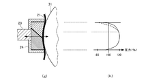
図3は第1の実施形態におけるニップ形成部材の側面図(a)およびニップ部内面圧分布図(b)である。
ニップ形成部材26は、側面図(a)に示すように定着ベルトの走行方向に直交する分割線により2分割された第1の部材261と第2の部材262から構成されている。なお、分割数は2に限定されることはない。
[First Embodiment]
FIG. 3 is a side view (a) and a nip portion inner surface pressure distribution diagram (b) of the nip forming member in the first embodiment.
As shown in the side view (a), the
また、支持部材23には、筐体24が取り付けられており、2分割された部材261と262を一体に保持している。
そして、ニップ部上流側に配置される第1の部材261の硬度を、ニップ部下流側に配置される第2の部材262の硬度よりも大きくする。
ニップ形成部材26は耐熱性に優れたLCP(液晶ポリマ)製とすることが望ましく、本実施形態においては、第2の部材262のRスケールで表したロックウエル硬度を第1の部材261のRスケールで表したロックウエル硬度の0.58倍とした。
A
Then, the hardness of the
The
ニップ部内面圧分布図(b)において、実線は幅方向の幅方向の分割線により2分割した場合の内面圧分布を、破線は従来からの一体型の場合の内面圧分布を示している。
すなわち、ニップ形成部材を2分割し、ニップ下流側の硬度を小さくすることにより、内面圧は減少する。
したがって、定着ベルト21の記録媒体Pに対する押圧も減少し、ニップ出口における定着ベルト21と記録媒体Pの分離性が向上することとなる。
In the nip portion internal pressure distribution diagram (b), the solid line indicates the internal pressure distribution when divided into two by the widthwise dividing line, and the broken line indicates the internal pressure distribution in the case of the conventional integrated type.
That is, the inner pressure is reduced by dividing the nip forming member into two parts and reducing the hardness on the downstream side of the nip.
Therefore, the pressing of the fixing
[第2の実施形態]
図4は第2の実施形態におけるニップ形成部材の側面図(c)およびニップ部内温度分布図(d)である。
ニップ形成部材26は、側面図(c)に示すように定着ベルトの幅方向の分割線により2分割された第3の部材263と第4の部材264から構成されている。なお、分割数は2に限定されることはない。
[Second Embodiment]
FIG. 4 is a side view (c) and a temperature distribution diagram (d) in the nip portion of the nip forming member in the second embodiment.
As shown in the side view (c), the
また、保持部材23には、筐体24が取り付けられており、2分割された部材261と262を一体に保持している。
そして、ニップ部下流側に配置される第4の部材264の熱伝導率を、ニップ部上流側に配置される第3の部材263の熱伝導率よりも大きくする。
ニップ形成部材26は耐熱性に優れたLCP(液晶ポリマ)製とすることが望ましい。
A
Then, the thermal conductivity of the
The
本実施形態においては、第3の部材263としてLCPをそのまま使用し、第4の部材264はLCPに熱伝導性フィラーを添加したものとし、第4の部材264の熱伝導率を第3の部材263の熱伝導率の1.4倍とした。
In the present embodiment, the LCP is used as it is as the third member 263, the
ニップ部内温度分布図(d)において、実線は幅方向に2分割した場合の内面圧分布を、破線は従来からの一体型の場合の内面圧分布を示している。
すなわち、ニップ形成部材を2分割し、ニップ下流側の部材の熱伝導率を大きくすることにより、ニップ部下流側の温度は低下する。
したがって、ニップ部下流側で定着ベルト21および記録媒体Pの温度も低下し、ニップ出口における定着ベルト21と記録媒体Pの分離性が向上することとなる。
In the temperature distribution diagram (d) in the nip portion, the solid line shows the internal pressure distribution when divided into two in the width direction, and the broken line shows the internal pressure distribution in the case of the conventional integrated type.
That is, by dividing the nip forming member into two parts and increasing the thermal conductivity of the member on the downstream side of the nip, the temperature on the downstream side of the nip portion is lowered.
Accordingly, the temperatures of the fixing
[第3の実施形態]
第3の実施形態においては、ニップ形成部材を分割した場合の各部材間のギャップの影響を検討する。
図5は、第1の実施形態における第1の部材261と第2の部材262の間に0.3ミリメートルのギャップを設けた場合の断面図(e)およびニップ部内面圧分布図(f)である。
[Third Embodiment]
In the third embodiment, the influence of the gap between each member when the nip forming member is divided is examined.
FIG. 5 is a cross-sectional view (e) and a nip portion internal pressure distribution diagram (f) when a gap of 0.3 mm is provided between the
ニップ部内面圧分布図(f)から判るように、第1の部材261と第2の部材262の間にギャップが存在すると、ニップ部内面圧に短周期の脈動が発生する。
この脈動は、定着ベルト21に微妙な撓み、応力集中を引き起こし、ジター画像の原因となるだけでなく、定着ベルト21の寿命を縮めることとなる。
したがって、第1の部材261と第2の部材262は定着ベルト21の内周において密着している必要がある。
As can be seen from the nip inner surface pressure distribution diagram (f), if there is a gap between the
This pulsation causes a slight deflection and stress concentration in the fixing
Therefore, the
[第4の実施形態]
第4の実施形態においては、ニップ形成部材を分割した場合の境界面の方向の影響を検討する。
図6は、第1の実施形態における第1の部材261と第2の部材262の間の境界面を加圧部材31の加圧方向に対して傾斜させた場合の断面図(g)およびニップ部内面圧分布図(h)である。
なお、ニップ部内面圧分布図(h)において、破線は第1の実施形態(図3)のように第1の部材261と第2の部材262の間の境界面を加圧ローラ31の加圧方向と平行にした場合のニップ部内面圧分布を示している。
[Fourth Embodiment]
In the fourth embodiment, the influence of the direction of the boundary surface when the nip forming member is divided is examined.
FIG. 6 is a cross-sectional view (g) and a nip when the boundary surface between the
In the nip inner surface pressure distribution diagram (h), the broken line indicates the boundary surface between the
このニップ部内面圧分布図(h)から判るように、第1の部材261と第2の部材262の間の境界面を加圧ローラ31の加圧方向に対して傾斜させると、ニップ部下流におけるニップ部内面圧の減少量が少なくなり、ニップ形成部材を分割した効果は低減する。
よって、ニップ形成部材26は、境界面が加圧ローラ31の加圧方向と平行になるように分離することが望ましいことが判る。
As can be seen from this nip inner surface pressure distribution diagram (h), when the boundary surface between the
Therefore, it can be seen that it is desirable to separate the
なお、第2の実施例においても、境界面を斜めとした場合には第1の部材と第2の部材の接触面積が増大し温度が均一化し易くなるので、境界面を加圧部材31の加圧方向と平行になるようにすることが望ましい。 Also in the second embodiment, when the boundary surface is slanted, the contact area between the first member and the second member increases and the temperature is easily uniformed. It is desirable to be parallel to the pressing direction.
[第5の実施形態]
図7は第5の実施形態のニップ形成部材の側面図(i)ならびにニップ部内温度分布図(その1)(j)およびニップ部内温度分布図(その2)(k)である。
すなわち、本実施形態においては、筐体24の第2の部材262の収納部分に放熱部材27を設置し、第2の部材262の温度を低下させるようにしている。
[Fifth Embodiment]
FIG. 7 is a side view (i) of the nip forming member of the fifth embodiment, a nip temperature distribution diagram (part 1) (j), and a nip temperature distribution diagram (part 2) (k).
That is, in the present embodiment, the heat radiating member 27 is installed in the housing portion of the
ニップ部内温度分布図(その1)(j)は1枚目を複写する際の温度分布であり、ニップ部内温度分布図(その2)(k)は連続して100枚を複写した後の温度分布を示す。
なお、破線は、ニップ形成部材として従来の一体型部材を使用した場合の温度分布である。
連続して複写すれば全体的な温度上昇は不可避ではあるが、放熱部材27を設置することによりニップ部下流の温度を効果的に低下することが可能となる。
Nip temperature distribution (No. 1) (j) is the temperature distribution when the first sheet is copied, and Nip temperature distribution (No. 2) (k) is the temperature after 100 sheets are copied continuously. Show the distribution.
In addition, a broken line is a temperature distribution at the time of using the conventional integrated member as a nip formation member.
If copying is performed continuously, the overall temperature rise is unavoidable, but by installing the heat dissipating member 27, the temperature downstream of the nip portion can be effectively lowered.
1 画像形成装置
3 露光部
4Y、4M、4C、4K 作像部
5Y、5M、5C、5K 感光体ドラム
12 給紙部
20 定着装置
21 定着ベルト
23 保持部材
24 筐体
25 ヒータ
26 ニップ形成部材
27 放熱部材
31 加圧ローラ
75 帯電部
76 現像部
77 クリーニング部
78 中間転写ベルト
79Y、79M、79C、79K、 1次転写バイアスローラ
80 中間転写クリーニング部
82 2次転写バックアップローラ
83 クリーニングバックアップローラ
84 テンションローラ
85 中間転写ユニット
89 2次転写ローラ
97 給紙ローラ
98 レジストローラ対
99 排紙ローラ対
100 スタック部
101 ボトル収容部
102Y、102M、102C、102K トナーボトル
261 第1の部材
262 第2の部材
263 第3の部材
264 第4の部材
DESCRIPTION OF SYMBOLS 1
Claims (7)
前記定着部材を加熱する熱源と、
前記定着部材と圧接する加圧部材と、
前記定着部材に内包され、前記定着部材を前記加圧部材に押圧してニップ部を形成するニップ形成部材と、を備え、
前記ニップ形成部材が前記定着部材の走行方向と直交する分割線により少なくとも2つに分離された複数の部材から成り、ニップ部下流側の部材が他の部材と比較して前記加圧部材との接触面における面圧、温度の少なくとも一方を低減する物性を有する定着装置。 An endless fixing member having flexibility;
A heat source for heating the fixing member;
A pressure member in pressure contact with the fixing member;
A nip forming member included in the fixing member and forming a nip portion by pressing the fixing member against the pressure member,
The nip forming member is composed of a plurality of members separated by at least two dividing lines perpendicular to the traveling direction of the fixing member, and the member on the downstream side of the nip portion is in contact with the pressure member as compared with other members. A fixing device having physical properties for reducing at least one of surface pressure and temperature at a contact surface.
前記定着部として請求項1から請求項6のいずれか一項に記載の定着装置を搭載する画像形成装置。 An image forming apparatus including a fixing unit that performs a fixing process on a recording medium on which an image is formed in the image forming unit,
An image forming apparatus in which the fixing device according to any one of claims 1 to 6 is mounted as the fixing unit.
Priority Applications (1)
| Application Number | Priority Date | Filing Date | Title |
|---|---|---|---|
| JP2012046841A JP2013182190A (en) | 2012-03-02 | 2012-03-02 | Fixation device and image formation apparatus |
Applications Claiming Priority (1)
| Application Number | Priority Date | Filing Date | Title |
|---|---|---|---|
| JP2012046841A JP2013182190A (en) | 2012-03-02 | 2012-03-02 | Fixation device and image formation apparatus |
Publications (1)
| Publication Number | Publication Date |
|---|---|
| JP2013182190A true JP2013182190A (en) | 2013-09-12 |
Family
ID=49272854
Family Applications (1)
| Application Number | Title | Priority Date | Filing Date |
|---|---|---|---|
| JP2012046841A Pending JP2013182190A (en) | 2012-03-02 | 2012-03-02 | Fixation device and image formation apparatus |
Country Status (1)
| Country | Link |
|---|---|
| JP (1) | JP2013182190A (en) |
Cited By (1)
| Publication number | Priority date | Publication date | Assignee | Title |
|---|---|---|---|---|
| JP2015132722A (en) * | 2014-01-14 | 2015-07-23 | 富士ゼロックス株式会社 | Fixing apparatus, sliding member, and image forming apparatus |
Citations (7)
| Publication number | Priority date | Publication date | Assignee | Title |
|---|---|---|---|---|
| JPH09244438A (en) * | 1996-03-04 | 1997-09-19 | Minolta Co Ltd | Fixing device |
| JPH1048868A (en) * | 1996-07-30 | 1998-02-20 | Canon Inc | Fixing device |
| JP2005092080A (en) * | 2003-09-19 | 2005-04-07 | Ricoh Co Ltd | Fixing device and image forming device provided with the same |
| JP2006258953A (en) * | 2005-03-15 | 2006-09-28 | Fuji Xerox Co Ltd | Cooling conveyance device and image forming apparatus using same |
| JP2007147905A (en) * | 2005-11-25 | 2007-06-14 | Fuji Xerox Co Ltd | Fixing device and image forming apparatus |
| JP2008107390A (en) * | 2006-10-23 | 2008-05-08 | Konica Minolta Business Technologies Inc | Fixing device and image forming apparatus |
| JP2009042305A (en) * | 2007-08-06 | 2009-02-26 | Ricoh Co Ltd | Fixing device and image forming apparatus with the same |
-
2012
- 2012-03-02 JP JP2012046841A patent/JP2013182190A/en active Pending
Patent Citations (7)
| Publication number | Priority date | Publication date | Assignee | Title |
|---|---|---|---|---|
| JPH09244438A (en) * | 1996-03-04 | 1997-09-19 | Minolta Co Ltd | Fixing device |
| JPH1048868A (en) * | 1996-07-30 | 1998-02-20 | Canon Inc | Fixing device |
| JP2005092080A (en) * | 2003-09-19 | 2005-04-07 | Ricoh Co Ltd | Fixing device and image forming device provided with the same |
| JP2006258953A (en) * | 2005-03-15 | 2006-09-28 | Fuji Xerox Co Ltd | Cooling conveyance device and image forming apparatus using same |
| JP2007147905A (en) * | 2005-11-25 | 2007-06-14 | Fuji Xerox Co Ltd | Fixing device and image forming apparatus |
| JP2008107390A (en) * | 2006-10-23 | 2008-05-08 | Konica Minolta Business Technologies Inc | Fixing device and image forming apparatus |
| JP2009042305A (en) * | 2007-08-06 | 2009-02-26 | Ricoh Co Ltd | Fixing device and image forming apparatus with the same |
Cited By (1)
| Publication number | Priority date | Publication date | Assignee | Title |
|---|---|---|---|---|
| JP2015132722A (en) * | 2014-01-14 | 2015-07-23 | 富士ゼロックス株式会社 | Fixing apparatus, sliding member, and image forming apparatus |
Similar Documents
| Publication | Publication Date | Title |
|---|---|---|
| JP5625779B2 (en) | Fixing apparatus and image forming apparatus | |
| JP6857324B2 (en) | Fixing device and image forming device | |
| JP5408553B2 (en) | Fixing apparatus and image forming apparatus | |
| JP5381746B2 (en) | Fixing apparatus and image forming apparatus | |
| JP5549160B2 (en) | Fixing apparatus and image forming apparatus | |
| JP5515906B2 (en) | Fixing apparatus and image forming apparatus | |
| JP2014013377A (en) | Fixing device and image forming apparatus | |
| JP2011064767A (en) | Fixing device and image forming apparatus | |
| JP2012145708A (en) | Fixing device and image forming device equipped with the same | |
| JP6137101B2 (en) | Fixing apparatus and image forming apparatus | |
| JP6462204B2 (en) | Fixing apparatus and image forming apparatus | |
| JP2013186192A (en) | Fixing device and image forming apparatus equipped with the same | |
| JP6278141B2 (en) | Fixing apparatus and image forming apparatus | |
| JP2024023903A (en) | Fixing device and image forming device | |
| JP2018060235A (en) | Fixation device and image formation device | |
| JP2019008159A (en) | Fixing device and image forming apparatus | |
| JP2013182190A (en) | Fixation device and image formation apparatus | |
| JP5750869B2 (en) | Fixing apparatus and image forming apparatus | |
| JP2012103478A (en) | Fixation device and image formation device | |
| JP2013178327A (en) | Fixation device and image formation apparatus | |
| JP5818180B2 (en) | Fixing apparatus and image forming apparatus | |
| JP2020016772A (en) | Fixing device and image forming apparatus | |
| JP6226230B2 (en) | Fixing apparatus and image forming apparatus | |
| JP2013186300A (en) | Fixing device and image forming apparatus | |
| JP2013186259A (en) | Fixing device and image forming apparatus |
Legal Events
| Date | Code | Title | Description |
|---|---|---|---|
| A621 | Written request for application examination |
Free format text: JAPANESE INTERMEDIATE CODE: A621 Effective date: 20150217 |
|
| A977 | Report on retrieval |
Free format text: JAPANESE INTERMEDIATE CODE: A971007 Effective date: 20151125 |
|
| A131 | Notification of reasons for refusal |
Free format text: JAPANESE INTERMEDIATE CODE: A131 Effective date: 20151201 |
|
| A521 | Written amendment |
Free format text: JAPANESE INTERMEDIATE CODE: A523 Effective date: 20160129 |
|
| A131 | Notification of reasons for refusal |
Free format text: JAPANESE INTERMEDIATE CODE: A131 Effective date: 20160329 |
|
| A02 | Decision of refusal |
Free format text: JAPANESE INTERMEDIATE CODE: A02 Effective date: 20161018 |