JP2013179563A - Video processing device, video display device, video recording device, video processing method, and video processing program - Google Patents

Video processing device, video display device, video recording device, video processing method, and video processing program Download PDF

Info

Publication number
JP2013179563A
JP2013179563A JP2012216082A JP2012216082A JP2013179563A JP 2013179563 A JP2013179563 A JP 2013179563A JP 2012216082 A JP2012216082 A JP 2012216082A JP 2012216082 A JP2012216082 A JP 2012216082A JP 2013179563 A JP2013179563 A JP 2013179563A
Authority
JP
Japan
Prior art keywords
telop
video
area
video processing
video frame
Prior art date
Legal status (The legal status is an assumption and is not a legal conclusion. Google has not performed a legal analysis and makes no representation as to the accuracy of the status listed.)
Pending
Application number
JP2012216082A
Other languages
Japanese (ja)
Other versions
JP2013179563A5 (en
Inventor
Isao Otsuka
功 大塚
Tomokazu Fukuda
智教 福田
Current Assignee (The listed assignees may be inaccurate. Google has not performed a legal analysis and makes no representation or warranty as to the accuracy of the list.)
Mitsubishi Electric Corp
Original Assignee
Mitsubishi Electric Corp
Priority date (The priority date is an assumption and is not a legal conclusion. Google has not performed a legal analysis and makes no representation as to the accuracy of the date listed.)
Filing date
Publication date
Application filed by Mitsubishi Electric Corp filed Critical Mitsubishi Electric Corp
Priority to JP2012216082A priority Critical patent/JP2013179563A/en
Publication of JP2013179563A publication Critical patent/JP2013179563A/en
Publication of JP2013179563A5 publication Critical patent/JP2013179563A5/ja
Pending legal-status Critical Current

Links

Images

Classifications

    • GPHYSICS
    • G11INFORMATION STORAGE
    • G11BINFORMATION STORAGE BASED ON RELATIVE MOVEMENT BETWEEN RECORD CARRIER AND TRANSDUCER
    • G11B27/00Editing; Indexing; Addressing; Timing or synchronising; Monitoring; Measuring tape travel
    • G11B27/02Editing, e.g. varying the order of information signals recorded on, or reproduced from, record carriers
    • G11B27/031Electronic editing of digitised analogue information signals, e.g. audio or video signals
    • GPHYSICS
    • G11INFORMATION STORAGE
    • G11BINFORMATION STORAGE BASED ON RELATIVE MOVEMENT BETWEEN RECORD CARRIER AND TRANSDUCER
    • G11B27/00Editing; Indexing; Addressing; Timing or synchronising; Monitoring; Measuring tape travel
    • G11B27/10Indexing; Addressing; Timing or synchronising; Measuring tape travel
    • G11B27/19Indexing; Addressing; Timing or synchronising; Measuring tape travel by using information detectable on the record carrier
    • G11B27/28Indexing; Addressing; Timing or synchronising; Measuring tape travel by using information detectable on the record carrier by using information signals recorded by the same method as the main recording
    • HELECTRICITY
    • H04ELECTRIC COMMUNICATION TECHNIQUE
    • H04NPICTORIAL COMMUNICATION, e.g. TELEVISION
    • H04N5/00Details of television systems
    • H04N5/76Television signal recording
    • HELECTRICITY
    • H04ELECTRIC COMMUNICATION TECHNIQUE
    • H04NPICTORIAL COMMUNICATION, e.g. TELEVISION
    • H04N9/00Details of colour television systems
    • H04N9/79Processing of colour television signals in connection with recording
    • H04N9/80Transformation of the television signal for recording, e.g. modulation, frequency changing; Inverse transformation for playback
    • H04N9/82Transformation of the television signal for recording, e.g. modulation, frequency changing; Inverse transformation for playback the individual colour picture signal components being recorded simultaneously only
    • H04N9/8205Transformation of the television signal for recording, e.g. modulation, frequency changing; Inverse transformation for playback the individual colour picture signal components being recorded simultaneously only involving the multiplexing of an additional signal and the colour video signal

Landscapes

  • Engineering & Computer Science (AREA)
  • Multimedia (AREA)
  • Signal Processing (AREA)
  • Television Signal Processing For Recording (AREA)
  • Television Systems (AREA)
  • Two-Way Televisions, Distribution Of Moving Picture Or The Like (AREA)
  • Signal Processing For Digital Recording And Reproducing (AREA)

Abstract

PROBLEM TO BE SOLVED: To provide a video processing device which can selectively erase a telop accompanying a flash report voice.SOLUTION: A video processing device 2400 comprises: a telop detection unit 102 which detects a telop region containing a telop from a series of input video frames; a flash report voice detection unit 2401 which detects a flash report voice from a series of audio signals which are input corresponding to the series of video frames; and a video processing unit 105 which replaces the telop region in a video frame among the series of video frames in which frame the telop region was detected with an image obtained from a preceding video frame among the series of video frames before the telop region appears, and outputs a video frame which has had the telop region replaced. The video processing unit 105 selectively replaces the telop region accompanying a flash report voice on the basis of the result of detection by the flash report voice detection unit 2401.

Description

本発明は、映像処理装置、映像表示装置、映像記録装置、映像処理方法、および映像処理プログラムに関する。   The present invention relates to a video processing device, a video display device, a video recording device, a video processing method, and a video processing program.

デジタルテレビジョン放送で送信される画像信号には、画像に重畳されたテロップ(例えば、時刻表示、地震速報、ニュース速報などの文字情報)を含むものがある。このテロップの重畳により、本来の画像に加えて追加の情報を得ることができる。   Some image signals transmitted by digital television broadcasting include telops (for example, character information such as time display, earthquake breaking news, news breaking news) superimposed on images. By superimposing the telop, additional information can be obtained in addition to the original image.

特に、地震や洪水、台風などの自然災害に対する警報や、ミサイル攻撃やテロなどの有事情報、あるいはニュース速報などの緊急を要する情報については、テロップ表示の前後、またはテロップ表示中に、チャイムやブザー、音楽、電子音などによる速報音(あるいは警報音、チャイム)を鳴らし、視聴者がテロップに注目するようにしている。   In particular, warnings for natural disasters such as earthquakes, floods and typhoons, emergency information such as missile attacks and terrorism, and emergency information such as breaking news are available before and after the telop display or during the telop display. A warning sound (or alarm sound or chime) is emitted by music, electronic sound, etc., so that the viewer pays attention to the telop.

しかし、このテロップや速報音は、視聴者にとって不要である場合もある。特に、放送にて送られてくる画像信号や音声信号を記録し、その後再生して視聴する場合において、放送時から視聴までに十分な時間が経過した場合、テロップに含まれる情報は不要であることが多い。   However, the telop and breaking sound may be unnecessary for the viewer. In particular, when a video signal or audio signal sent by broadcasting is recorded, and then played back and viewed, the information contained in the telop is not required if sufficient time has elapsed from the time of broadcasting to viewing. There are many cases.

特許文献1には、第1の画像信号のうちテロップ領域に対応した画素信号を、第1の画像信号と同一のコンテンツに係る、テロップが存在しない第2の画像信号の画素信号で置き換えることにより、テロップを削除する技術が記載されている。具体的には、第1の画像信号は、地上波デジタル放送の12セグメントで行われるハイビジョン(HDTV)放送の画像信号であり、第2の画像信号は、地上波デジタル放送の部分受信階層に割り当てられている1セグメントで行われる放送(以下、ワンセグ放送と呼ぶ)の画像信号である。   In Patent Document 1, a pixel signal corresponding to a telop area in the first image signal is replaced with a pixel signal of a second image signal that does not have a telop and has the same content as the first image signal. A technique for deleting telops is described. Specifically, the first image signal is an image signal for high-definition (HDTV) broadcasting performed in 12 segments of terrestrial digital broadcasting, and the second image signal is assigned to a partial reception layer for terrestrial digital broadcasting. This is an image signal of broadcasting (hereinafter referred to as one-segment broadcasting) performed in one segment.

非特許文献1には、ラジオの緊急地震速報チャイムを受信したら、音声をONにする装置が示されており、放送番組の音声信号の周波数特性を観測して特定の4つの周波数の振幅をしきい値と比較して緊急地震速報チャイムの判定を行う技術が掲載されている。   Non-Patent Document 1 shows a device that turns on the sound when a radio emergency earthquake warning chime is received, and observes the frequency characteristics of the audio signal of the broadcast program to obtain amplitudes of four specific frequencies. A technique for determining the earthquake early warning chime compared to the threshold is published.

特開2007−336405号公報JP 2007-336405 A 特開2009−93472号公報JP 2009-93472 A 特開2007−180669号公報JP 2007-180669 A

「緊急地震速報受信機の製作」、[online]、トランジスタ技術、2009年1月号、CQ出版社、インターネット<URL:http://toragi.cqpub.co.jp/tabid/256/Default.aspx>“Production of Earthquake Early Warning Receiver”, [online], Transistor Technology, January 2009, CQ Publisher, Internet <URL: http://toragi.cqpub.co.jp/tabid/256/Default.aspx >

ところで、速報音を伴うテロップは本来の映像とは関係のないテロップである可能性が高く、このようなテロップを消去することが望ましい場合がある。   By the way, there is a high possibility that a telop accompanied by a breaking sound is a telop unrelated to the original video, and it may be desirable to delete such a telop.

本発明は、速報音を伴うテロップを選択的に消去することができる映像処理装置、映像表示装置、映像記録装置、映像処理方法、および映像処理プログラムを提供することを目的とする。   An object of the present invention is to provide a video processing device, a video display device, a video recording device, a video processing method, and a video processing program capable of selectively erasing a telop accompanied by a breaking sound.

本発明に係る映像処理装置は、入力される一連の映像フレームからテロップを含むテロップ領域を検出するテロップ検出部と、前記一連の映像フレームに対応し、入力される一連の音声信号から速報音を検出する速報音検出部と、前記一連の映像フレームのうち前記テロップ領域が検出された映像フレームにおける前記テロップ領域を、前記一連の映像フレームのうち前記テロップ領域のテロップが出現する前の映像フレームから得られる画像に置き換え、前記テロップ領域が置き換えられた映像フレームを出力する映像処理部とを備え、前記映像処理部は、前記速報音検出部の検出結果に基づき、前記速報音を伴うテロップのテロップ領域を選択的に置き換えることを特徴とする。   A video processing apparatus according to the present invention includes a telop detection unit that detects a telop area including a telop from a series of input video frames, and a breaking sound from a series of input audio signals corresponding to the series of video frames. A breaking sound detection unit to detect, and the telop area in the video frame in which the telop area is detected in the series of video frames, from the video frame before the telop in the telop area appears in the series of video frames A video processing unit that outputs a video frame in which the telop area is replaced with the obtained image, and the video processing unit, based on a detection result of the breaking sound detection unit, the telop of the telop with the breaking sound It is characterized by selectively replacing the region.

本発明に係る映像表示装置は、上記映像処理装置と、前記映像処理装置の前記映像処理部から出力される映像フレームを表示する再生部と、を備えることを特徴とする。   A video display device according to the present invention includes the video processing device and a playback unit that displays a video frame output from the video processing unit of the video processing device.

本発明に係る映像記録装置は、上記映像処理装置と、前記映像処理装置の前記映像処理部から出力される映像フレームを記録する記録部と、を備えることを特徴とする。   A video recording apparatus according to the present invention includes the video processing apparatus and a recording unit that records a video frame output from the video processing unit of the video processing apparatus.

本発明に係る映像処理方法は、入力される一連の映像フレームからテロップを含むテロップ領域を検出するテロップ検出ステップと、前記一連の映像フレームに対応し、入力される一連の音声信号から速報音を検出する速報音検出ステップと、前記一連の映像フレームのうち前記テロップ領域が検出された映像フレームにおける前記テロップ領域を、前記一連の映像フレームのうち前記テロップ領域のテロップが出現する前の映像フレームから得られる画像に置き換え、前記テロップ領域が置き換えられた映像フレームを出力する映像処理ステップとを有し、前記映像処理ステップは、前記速報音検出部の検出結果に基づき、前記速報音を伴うテロップのテロップ領域を選択的に置き換えることを特徴とする。   The video processing method according to the present invention includes a telop detection step for detecting a telop area including a telop from a series of input video frames, and a breaking sound from a series of input audio signals corresponding to the series of video frames. A preliminary sound detection step to detect, and the telop area in the video frame in which the telop area is detected in the series of video frames, from the video frame before the telop in the telop area appears in the series of video frames. A video processing step of outputting a video frame in which the telop area is replaced with the obtained image, and the video processing step is based on a detection result of the quick sound detection unit, The telop area is selectively replaced.

本発明に係る映像処理プログラムは、入力される一連の映像フレームからテロップを含むテロップ領域を検出するテロップ検出ステップと、前記一連の映像フレームに対応し、入力される一連の音声信号から速報音を検出する速報音検出ステップと、前記一連の映像フレームのうち前記テロップ領域が検出された映像フレームにおける前記テロップ領域を、前記一連の映像フレームのうち前記テロップ領域のテロップが出現する前の映像フレームから得られる画像に置き換え、前記テロップ領域が置き換えられた映像フレームを出力する映像処理ステップと、をコンピュータに実行させ、前記映像処理ステップは、前記速報音検出部の検出結果に基づき、前記速報音を伴うテロップのテロップ領域を選択的に置き換えることを特徴とする。   A video processing program according to the present invention includes a telop detection step for detecting a telop area including a telop from a series of inputted video frames, and a breaking sound from a series of inputted audio signals corresponding to the series of video frames. A preliminary sound detection step to detect, and the telop area in the video frame in which the telop area is detected in the series of video frames, from the video frame before the telop in the telop area appears in the series of video frames. And a video processing step of outputting a video frame in which the telop area is replaced with the obtained image, and causing the computer to execute the video processing step based on a detection result of the quick sound detection unit. The telop area of the accompanying telop is selectively replaced.

本発明によれば、速報音を伴うテロップを選択的に消去することができる。   According to the present invention, it is possible to selectively delete a telop accompanied by a breaking sound.

実施の形態1に係る映像処理装置の構成を示すブロック図である。1 is a block diagram illustrating a configuration of a video processing apparatus according to Embodiment 1. FIG. 映像記録部の構成を示すブロック図である。It is a block diagram which shows the structure of a video recording part. 映像フレームに含まれるテロップ領域の一例を示す図である。It is a figure which shows an example of the telop area | region contained in a video frame. 実施の形態1に係る映像処理装置の動作を示すフローチャートである。3 is a flowchart showing an operation of the video processing apparatus according to the first embodiment. テロップ遷移の一例を示す図である。It is a figure which shows an example of telop transition. 映像記録部の状態の一例を示す図である。It is a figure which shows an example of the state of a video recording part. 映像記録部の状態の別の一例を示す図である。It is a figure which shows another example of the state of a video recording part. テロップ遷移の別の一例を示す図である。It is a figure which shows another example of telop transition. 実施の形態2に係る映像処理装置の構成を示すブロック図である。6 is a block diagram illustrating a configuration of a video processing apparatus according to Embodiment 2. FIG. テロップチェンジ検出部での検出情報を示す図である。It is a figure which shows the detection information in a telop change detection part. テロップの一例を示す図である。It is a figure which shows an example of a telop. テロップチェンジ検出部でのテロップチェンジ検出方法を説明するための図である。It is a figure for demonstrating the telop change detection method in a telop change detection part. テロップ領域を周辺画素から得られる画像に置き換える方法を説明するための図である。It is a figure for demonstrating the method of replacing a telop area | region with the image obtained from a surrounding pixel. テロップ領域を周辺画素から得られる画像に置き換える方法を説明するための図である。It is a figure for demonstrating the method of replacing a telop area | region with the image obtained from a surrounding pixel. 実施の形態2におけるステップS405の判定結果を示す図である。It is a figure which shows the determination result of step S405 in Embodiment 2. FIG. 実施の形態3に係る映像処理装置の構成を示すブロック図である。6 is a block diagram illustrating a configuration of a video processing apparatus according to Embodiment 3. FIG. 実施の形態3に係る映像処理装置の動作を示すフローチャートである。10 is a flowchart illustrating an operation of the video processing apparatus according to the third embodiment. 実施の形態4に係る映像処理装置の構成を示すブロック図である。FIG. 10 is a block diagram illustrating a configuration of a video processing device according to a fourth embodiment. 実施の形態5に係る映像処理装置の構成を示すブロック図である。FIG. 10 is a block diagram illustrating a configuration of a video processing device according to a fifth embodiment. 実施の形態6に係る映像処理装置の構成を示すブロック図である。FIG. 10 is a block diagram illustrating a configuration of a video processing device according to a sixth embodiment. 実施の形態7に係る映像処理装置の構成を示すブロック図である。FIG. 10 is a block diagram illustrating a configuration of a video processing device according to a seventh embodiment. 実施の形態7に係る映像処理装置の動作を示すフローチャートである。18 is a flowchart showing the operation of the video processing apparatus according to the seventh embodiment. テロップ遷移および速報音の一例を示す図である。It is a figure which shows an example of telop transition and a breaking news sound. テロップ遷移および速報音の別の一例を示す図である。It is a figure which shows another example of a telop transition and a breaking news sound. テロップ遷移および速報音のさらに別の一例を示す図である。It is a figure which shows another example of a telop transition and a breaking news sound. 実施の形態8に係る映像処理装置の動作を示すフローチャートである。20 is a flowchart showing the operation of the video processing apparatus according to the eighth embodiment. 実施の形態9に係る映像処理装置の動作を示すフローチャートである。24 is a flowchart showing the operation of the video processing apparatus according to the ninth embodiment. 実施の形態10に係る映像処理装置の構成を示すブロック図である。FIG. 22 is a block diagram showing a configuration of a video processing apparatus according to Embodiment 10. 実施の形態11に係る映像表示装置の構成を示す図である。FIG. 38 shows a configuration of a video display apparatus according to an eleventh embodiment. 実施の形態12に係る映像記録装置の構成を示す図である。FIG. 20 is a diagram showing a configuration of a video recording apparatus according to Embodiment 12. 実施の形態13に係る映像記録再生装置の構成を示す図である。FIG. 38 shows a structure of a video recording / reproducing apparatus according to Embodiment 13. 映像処理装置の変形例を示すブロック図である。It is a block diagram which shows the modification of a video processing apparatus.

以下、本発明の実施の形態を図面に従って説明する。
実施の形態1.
図1は、実施の形態1に係る映像処理装置100の構成を示すブロック図である。この映像処理装置100は、入力映像信号を受け、当該入力映像信号からテロップを含むテロップ領域を検出し、テロップ領域が検出された場合に、当該テロップ領域を置き換えて(または補間して)テロップが消去された出力映像信号を出力する。入力映像信号は、例えば、地上波デジタル放送における12セグメントを使って放送されるハイビジョン(HDTV)放送の映像信号などである。テロップとは、映像(例えば主映像または本来の映像)に重畳、挿入、または合成された、文字情報、記号情報、図形情報などの情報であり、例えば、時刻表示、地震速報、ニュース速報、字幕などである。テロップは、地域、内容、および形式によって、キャプション、サブタイトル、ティッカー、アラート、またはスーパーインポーズなどと呼ばれることもある。
Hereinafter, embodiments of the present invention will be described with reference to the drawings.
Embodiment 1 FIG.
FIG. 1 is a block diagram showing a configuration of a video processing apparatus 100 according to the first embodiment. The video processing apparatus 100 receives an input video signal, detects a telop area including a telop from the input video signal, and replaces (or interpolates) the telop area when a telop area is detected. The erased output video signal is output. The input video signal is, for example, a high-definition (HDTV) broadcast video signal broadcast using 12 segments in terrestrial digital broadcasting. A telop is information such as character information, symbol information, and graphic information superimposed, inserted, or synthesized on a video (for example, main video or original video), for example, time display, earthquake breaking news, breaking news, subtitles, etc. Etc. A telop may also be called a caption, subtitle, ticker, alert, or superimpose, depending on the region, content, and format.

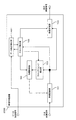
図1において、映像処理装置100は、映像記録部101、テロップ検出部102、テロップチェンジ検出部103、記録制御部104、および映像処理部105を有する。   In FIG. 1, the video processing apparatus 100 includes a video recording unit 101, a telop detection unit 102, a telop change detection unit 103, a recording control unit 104, and a video processing unit 105.

映像記録部101は、入力映像信号として、外部から一連の映像信号(具体的には、一連の映像フレーム)を受けメモリに記録する。ここで、映像フレームとは、動画像を構成する一つ一つの静止画像を指す。以下の説明では、「映像フレーム」を適宜「フレーム」と略称する。具体的には、映像記録部101には、一連の映像フレームが順次入力され、映像記録部101は、一連の映像フレームのうち、現在の映像フレームである現映像フレームと、当該現映像フレームの前の映像フレームとを記録する。また、映像記録部101は、一連の映像フレームのうち、テロップが出現する(またはテロップが表示される)前の映像フレームを記録する。テロップが出現する前の映像フレームは、好ましくはテロップが出現する直前の映像フレームであり、一つの態様では、テロップが出現した映像フレームの1つ前の映像フレームである。テロップの出現に対してどの程度前の映像フレームをテロップが出現する前の映像フレームとするかは適宜決められればよい。具体的には、テロップが出現する前の映像フレームは、テロップ領域を良好に置換または補間できる程度に前の映像フレームであればよく、例えばテロップが出現した映像フレームの数フレーム前の映像フレームであってもよい。   The video recording unit 101 receives a series of video signals (specifically, a series of video frames) from the outside as input video signals and records them in a memory. Here, the video frame refers to each still image constituting a moving image. In the following description, “video frame” is abbreviated as “frame” as appropriate. Specifically, a series of video frames are sequentially input to the video recording unit 101, and the video recording unit 101 includes a current video frame that is a current video frame and a current video frame among the series of video frames. Record previous video frame. In addition, the video recording unit 101 records a video frame before a telop appears (or a telop is displayed) in a series of video frames. The video frame before the appearance of the telop is preferably the video frame immediately before the appearance of the telop, and in one aspect, the video frame immediately before the video frame in which the telop appears. It suffices to determine appropriately how long the video frame before the appearance of the telop is the video frame before the appearance of the telop. Specifically, the video frame before the appearance of the telop may be the previous video frame to such an extent that the telop area can be satisfactorily replaced or interpolated. There may be.

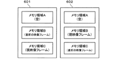
本例では、映像記録部101は、図2に示されるように、メモリ領域A、メモリ領域B、およびメモリ領域Cを含む。映像記録部101は、後述する記録制御部104の制御を受けてメモリを管理する。具体的には、映像記録部101は、記録制御部104からの制御信号に従い、現映像フレームとその直前の映像フレームとをメモリ領域Bおよびメモリ領域Cに保存し、テロップが出現する直前の映像フレームをメモリ領域Aに保存する。ここでは、映像記録部101は、フレームメモリであり、メモリ領域A,B,Cの各々に対し、1フレーム分の映像信号を記録する。ただし、映像記録部101は、メモリ領域A,B,Cの何れについても、1フレーム中の一部分(具体的にはテロップ部分のみ)を記録してもよい。一例では、メモリ領域に記録される1フレーム中の一部分は、予め決められた固定位置である。例えば、地上デジタル放送では映像の上部にテロップが表示される場合がほとんどであるので、映像記録部101は、図3に示されるように、映像フレームで表される映像全体の領域301のうち、上部の部分領域302の映像信号を記録してもよい。ただし、1フレーム中の一部分は、可変位置であってもよく、例えばテロップ検出部102の検出結果を利用して決められてもよい。   In this example, the video recording unit 101 includes a memory area A, a memory area B, and a memory area C as shown in FIG. The video recording unit 101 manages the memory under the control of a recording control unit 104 described later. Specifically, the video recording unit 101 stores the current video frame and the immediately preceding video frame in the memory area B and the memory area C in accordance with the control signal from the recording control unit 104, and the video immediately before the telop appears. The frame is stored in the memory area A. Here, the video recording unit 101 is a frame memory, and records a video signal for one frame in each of the memory areas A, B, and C. However, the video recording unit 101 may record a part of one frame (specifically, only the telop part) in any of the memory areas A, B, and C. In one example, a part of one frame recorded in the memory area is a predetermined fixed position. For example, in terrestrial digital broadcasting, a telop is almost always displayed at the top of the video, so the video recording unit 101, as shown in FIG. The video signal of the upper partial area 302 may be recorded. However, a part of one frame may be a variable position, and may be determined using the detection result of the telop detection unit 102, for example.

再び図1を参照すると、テロップ検出部102は、映像処理装置100に入力される一連の映像フレームから、テロップを含むテロップ領域を検出する。具体的には、テロップ検出部102は、映像記録部101により記録された現映像フレームについてテロップ領域の検出を行う。より具体的には、テロップ検出部102は、映像記録部101から現映像フレームを読み出し、当該現映像フレームを解析し、現映像フレームにテロップが含まれているかを判定する。そして、テロップ検出部102は、テロップが含まれていると判定した場合、当該テロップを含むテロップ領域を示す領域情報を検出結果として出力する。ここでは、テロップ検出部102は、テロップ領域として矩形領域を検出し、当該矩形領域の座標を領域情報として出力する。ただし、テロップ領域の形状は、矩形に限られず、例えば、台形、平行四辺形、楕円形などでもよい。また、テロップ領域は、テロップを構成する画素の集合であってもよい。一方、現映像フレームにテロップが含まれないと判定した場合には、テロップ検出部102は、テロップが含まれないことを示す情報(例えば原点の座標のみ)を検出結果として出力する。ただし、テロップ検出部102は、テロップが含まれないと判定した場合に、何も出力しないように構成されてもよい。テロップ検出部102でのテロップ検出アルゴリズムとしては、例えば、特許文献2に示されている方法が用いられる。ただし、この方法に限られず、テロップ領域を検出できる方法であれば、別の方法が用いられてもよい。   Referring again to FIG. 1, the telop detection unit 102 detects a telop area including a telop from a series of video frames input to the video processing apparatus 100. Specifically, the telop detection unit 102 detects a telop area for the current video frame recorded by the video recording unit 101. More specifically, the telop detection unit 102 reads the current video frame from the video recording unit 101, analyzes the current video frame, and determines whether a telop is included in the current video frame. When the telop detection unit 102 determines that a telop is included, the telop detection unit 102 outputs area information indicating a telop area including the telop as a detection result. Here, the telop detection unit 102 detects a rectangular area as the telop area, and outputs the coordinates of the rectangular area as area information. However, the shape of the telop area is not limited to a rectangle, and may be a trapezoid, a parallelogram, an ellipse, or the like. The telop area may be a set of pixels constituting the telop. On the other hand, when it is determined that no telop is included in the current video frame, the telop detection unit 102 outputs information indicating that no telop is included (for example, only the coordinates of the origin) as a detection result. However, the telop detection unit 102 may be configured not to output anything when it is determined that no telop is included. As the telop detection algorithm in the telop detection unit 102, for example, the method disclosed in Patent Document 2 is used. However, the present invention is not limited to this method, and another method may be used as long as the telop area can be detected.

テロップチェンジ検出部103は、映像処理装置100に入力される一連の映像フレームから、テロップの出現を検出する。具体的には、テロップチェンジ検出部103は、映像記録部101により記録された現映像フレームについてテロップの出現の検出を行う。一つの態様では、テロップチェンジ検出部103は、テロップ検出部102の検出結果に基づき、現映像フレームの直前の映像フレームにテロップが含まれず、現映像フレームにテロップが含まれる場合に、テロップの出現を示す情報を検出結果として出力する。別の態様では、テロップチェンジ検出部103は、映像記録部101から現映像フレームと現映像フレームの直前の映像フレームとを読み出し、両映像フレームを比較してテロップの出現を検出する。例えば、テロップチェンジ検出部103は、テロップを構成する文字のエッジおよび当該文字の輪郭部のエッジを検出し、検出されるエッジの変化に基づいてテロップの出現を検出する。このエッジに基づくテロップチェンジの検出については、実施の形態2で詳しく説明する。   The telop change detection unit 103 detects the appearance of a telop from a series of video frames input to the video processing device 100. Specifically, the telop change detection unit 103 detects the appearance of a telop for the current video frame recorded by the video recording unit 101. In one aspect, the telop change detection unit 103, based on the detection result of the telop detection unit 102, when a telop is not included in the video frame immediately before the current video frame and a telop is included in the current video frame, the appearance of the telop Is output as a detection result. In another aspect, the telop change detection unit 103 reads the current video frame and the video frame immediately before the current video frame from the video recording unit 101, and compares the two video frames to detect the appearance of the telop. For example, the telop change detection unit 103 detects the edge of a character constituting the telop and the edge of the outline of the character, and detects the appearance of the telop based on the detected edge change. The detection of the telop change based on the edge will be described in detail in the second embodiment.

テロップチェンジ検出部103は、映像処理装置100に入力される一連の映像フレームから、テロップの消滅を検出してもよい。例えば、テロップチェンジ検出部103は、テロップ検出部102の検出結果に基づき、現映像フレームの直前の映像フレームにテロップが含まれ、現映像フレームにテロップが含まれない場合に、テロップの消滅を示す情報を検出結果として出力してもよい。   The telop change detection unit 103 may detect the disappearance of the telop from a series of video frames input to the video processing device 100. For example, the telop change detection unit 103 indicates the disappearance of the telop when the telop is included in the video frame immediately before the current video frame and the telop is not included in the current video frame based on the detection result of the telop detection unit 102. Information may be output as a detection result.

記録制御部104は、テロップ検出部102およびテロップチェンジ検出部103の検出結果に基づき、映像記録部101を制御する。   The recording control unit 104 controls the video recording unit 101 based on the detection results of the telop detection unit 102 and the telop change detection unit 103.

具体的には、記録制御部104は、テロップチェンジ検出部103の検出結果に基づき、映像処理装置100に入力される一連の映像フレームのうち、テロップが出現する前の映像フレームを記録する。より具体的には、記録制御部104は、テロップチェンジ検出部103により現映像フレームについてテロップの出現が検出された場合に、映像記録部101を制御して、メモリ領域BまたはCに記録されている現映像フレームの直前の映像フレームを、テロップが出現する直前の映像フレームとしてメモリ領域Aに記録する。   Specifically, the recording control unit 104 records a video frame before the appearance of a telop among a series of video frames input to the video processing device 100 based on the detection result of the telop change detection unit 103. More specifically, the recording control unit 104 controls the video recording unit 101 when the telop change detection unit 103 detects the appearance of a telop for the current video frame, and is recorded in the memory area B or C. The video frame immediately before the current video frame is recorded in the memory area A as the video frame immediately before the telop appears.

記録制御部104は、テロップチェンジ検出部103により現映像フレームについてテロップの消滅が検出された場合、またはテロップ検出部102により現映像フレームについてテロップ無しが検出された場合に、映像記録部101を制御して、メモリ領域Aに記録されている映像フレームを消去してもよい。   The recording control unit 104 controls the video recording unit 101 when the telop change detection unit 103 detects the disappearance of the telop for the current video frame or when the telop detection unit 102 detects the absence of the telop for the current video frame. Then, the video frame recorded in the memory area A may be erased.

また、記録制御部104は、映像記録部101を制御して、映像処理装置100に入力される映像フレームを、メモリ領域Bおよびメモリ領域Cの一方に、フレーム毎に交互に記録する。すなわち、記録制御部104は、メモリ領域Bおよびメモリ領域Cの間で、現映像フレーム用のメモリ領域と、現映像フレームの直前の映像フレーム用のメモリ領域とが、フレーム毎に入れ替わるように、映像記録部101を制御する。   The recording control unit 104 also controls the video recording unit 101 to record video frames input to the video processing device 100 alternately in one of the memory area B and the memory area C for each frame. That is, the recording control unit 104 switches between the memory area B and the memory area C so that the memory area for the current video frame and the memory area for the video frame immediately before the current video frame are switched for each frame. The video recording unit 101 is controlled.

映像処理部105は、映像処理装置100に入力される一連の映像フレームのうち、テロップ検出部102によりテロップ領域が検出された映像フレームにおけるテロップ領域を、当該テロップ領域のテロップが出現する前の映像フレームから得られる画像に置き換える。すなわち、映像処理部105は、テロップ領域が検出された映像フレームにおけるテロップ領域を、当該テロップ領域のテロップが出現する前の映像フレームから補間する。例えば、映像処理部105は、テロップが出現する前の映像フレームからテロップのない置換画像を取得または生成し、テロップ領域を置換画像に置き換える。映像処理部105は、テロップが出現する前の映像フレームのうちテロップ領域に対応する領域の画像を置換画像として取得してもよいし、テロップ領域に対応する領域の画像に画像処理を施して置換画像を生成してもよい。上記テロップ領域に対応する領域は、テロップ領域と同一の領域であってもよいし、テロップ領域の画像と類似する画像を含む領域であってもよい。本例では、映像処理部105は、テロップ検出部102により現映像フレームについてテロップ領域が検出された場合に、メモリ領域BまたはCに記録された現映像フレームのテロップ領域を、メモリ領域Aに記録されたテロップが出現する直前の映像フレームから得られる画像に置き換え、テロップ領域が置き換えられた現映像フレームを出力映像フレームとして出力する。例えば、映像処理部105は、テロップ検出部102から領域情報を受け取り、現映像フレームのうち当該領域情報で示される領域(すなわちテロップ領域)の映像信号を、テロップが出現する直前の映像フレームのうち当該領域情報で示される領域(すなわちテロップ領域に対応する領域)の映像信号に置き換える。   The video processing unit 105 selects a telop area in the video frame in which the telop area is detected by the telop detection unit 102 from among a series of video frames input to the video processing apparatus 100, before the telop in the telop area appears. Replace with the image obtained from the frame. That is, the video processing unit 105 interpolates the telop area in the video frame in which the telop area is detected from the video frame before the appearance of the telop in the telop area. For example, the video processing unit 105 acquires or generates a replacement image without a telop from the video frame before the telop appears, and replaces the telop area with the replacement image. The video processing unit 105 may acquire an image of an area corresponding to the telop area in the video frame before the appearance of the telop as a replacement image, or performs image processing on the image of the area corresponding to the telop area and replaces the image. An image may be generated. The area corresponding to the telop area may be the same area as the telop area, or may be an area including an image similar to the image in the telop area. In this example, the video processing unit 105 records the telop area of the current video frame recorded in the memory area B or C in the memory area A when the telop detection unit 102 detects the telop area for the current video frame. The current video frame with the telop area replaced is output as an output video frame by replacing it with an image obtained from the video frame immediately before the generated telop appears. For example, the video processing unit 105 receives the region information from the telop detection unit 102, and outputs the video signal of the region indicated by the region information (that is, the telop region) in the current video frame among the video frames immediately before the appearance of the telop. It replaces with the video signal of the area indicated by the area information (that is, the area corresponding to the telop area).

図4は、実施の形態1に係る映像処理装置100の動作を示すフローチャートである。以下、図4を参照して、映像処理装置100の動作について説明する。なお、図4の処理はフレーム毎に実行される。   FIG. 4 is a flowchart showing the operation of the video processing apparatus 100 according to the first embodiment. Hereinafter, the operation of the video processing apparatus 100 will be described with reference to FIG. Note that the processing of FIG. 4 is executed for each frame.

映像処理装置100は、入力された映像フレーム(または1フレーム分の映像信号)を現映像フレームとして現映像フレーム用のメモリ領域(メモリ領域BまたはC)に記録する(S401)。   The video processing apparatus 100 records the input video frame (or video signal for one frame) as a current video frame in a memory area (memory area B or C) for the current video frame (S401).

次に、映像処理装置100は、現映像フレーム用のメモリ領域に記録された映像フレームについてテロップ領域の検出を行う(S402)。   Next, the video processing apparatus 100 detects a telop area for the video frame recorded in the memory area for the current video frame (S402).

次に、映像処理装置100は、現映像フレーム用のメモリ領域に記録された現映像フレームについて、テロップチェンジ(テロップの出現および消滅)の検出を行う(S403)。   Next, the video processing apparatus 100 detects a telop change (the appearance and disappearance of a telop) for the current video frame recorded in the memory area for the current video frame (S403).

次に、映像処理装置100は、ステップS402でテロップ領域が検出されたか否かを判定し(S404)、検出された場合には(S404:YES)、ステップS405へ進み、検出されなかった場合には(S404:NO)、ステップS408へ進む。   Next, the video processing apparatus 100 determines whether or not a telop area is detected in step S402 (S404). If it is detected (S404: YES), the process proceeds to step S405, and if it is not detected. (S404: NO), the process proceeds to step S408.

ステップS405では、映像処理装置100は、ステップS403でテロップの出現が検出されたか否かを判定し、検出された場合には(S405:YES)、ステップS406へ進み、検出されなかった場合には(S405:NO)、ステップS407へ進む。   In step S405, the video processing apparatus 100 determines whether or not the appearance of a telop has been detected in step S403. If it is detected (S405: YES), the process proceeds to step S406. (S405: NO), the process proceeds to step S407.

ステップS406では、映像処理装置100は、現映像フレームの直前の映像フレーム用のメモリ領域に記録されている映像フレーム(すなわち前回のステップS401で記録された映像フレーム)を、テロップが出現する直前の映像フレーム用のメモリ領域Aに記録し、ステップS407へ進む。   In step S406, the video processing device 100 uses the video frame recorded in the memory area for the video frame immediately before the current video frame (that is, the video frame recorded in the previous step S401) immediately before the telop appears. Recording is performed in the memory area A for the video frame, and the process proceeds to step S407.

ステップS407では、映像処理装置100は、現映像フレーム用のメモリ領域から現映像フレームを読み出し、当該現映像フレームのうちステップS402で検出されたテロップ領域の画像を、メモリ領域Aに記録されているテロップが出現する直前の映像フレームから得られる画像に置き換えて、テロップが消去された現映像フレームを出力映像フレームとして出力し、ステップS411へ進む。   In step S407, the video processing apparatus 100 reads the current video frame from the memory area for the current video frame, and the telop area image detected in step S402 of the current video frame is recorded in the memory area A. The current video frame from which the telop is deleted is output as an output video frame by replacing the image obtained from the video frame immediately before the telop appears, and the process proceeds to step S411.

ステップS408では、映像処理装置100は、ステップS403でテロップの消滅が検出されたか否かを判定し、検出された場合には(S408:YES)、ステップS409へ進み、検出されなかった場合には(S408:NO)、ステップS410へ進む。   In step S408, the video processing apparatus 100 determines whether or not the disappearance of the telop is detected in step S403. If it is detected (S408: YES), the process proceeds to step S409, and if not detected, (S408: NO), the process proceeds to step S410.

ステップS409では、映像処理装置100は、メモリ領域Aをクリアし、ステップS410へ進む。   In step S409, the video processing apparatus 100 clears the memory area A, and proceeds to step S410.

ステップS410では、映像処理装置100は、現映像フレーム用のメモリ領域から現映像フレームを読み出し、当該現映像フレームを出力映像フレームとして出力し、ステップS411へ進む。   In step S410, the video processing apparatus 100 reads the current video frame from the memory area for the current video frame, outputs the current video frame as an output video frame, and proceeds to step S411.

ステップS411では、映像処理装置100は、メモリ領域Bとメモリ領域Cとの間で、現映像フレーム用のメモリ領域と、現映像フレームの直前の映像フレーム用のメモリ領域とを入れ替える処理を行い、処理を終了させる。   In step S411, the video processing apparatus 100 performs a process of exchanging the memory area for the current video frame and the memory area for the video frame immediately before the current video frame between the memory area B and the memory area C, End the process.

上記の動作において、例えば、ステップS401は映像記録部101により実行され、ステップS402はテロップ検出部102により実行され、ステップS403はテロップチェンジ検出部103により実行され、ステップS404〜S406,S408〜S409,S411は記録制御部104により実行され、ステップS407,S410は映像処理部105により実行される。   In the above operation, for example, Step S401 is executed by the video recording unit 101, Step S402 is executed by the telop detection unit 102, Step S403 is executed by the telop change detection unit 103, Steps S404 to S406, S408 to S409, S411 is executed by the recording control unit 104, and steps S407 and S410 are executed by the video processing unit 105.

なお、図4において、ステップS408は省略されてもよく、映像処理装置100は、ステップS404の判定結果が「NO」である場合にステップS409へ進んでもよい。また、ステップS408およびS409が省略されてもよく、映像処理装置100は、ステップS404の判定結果が「NO」である場合にステップS410へ進んでもよい。   In FIG. 4, step S <b> 408 may be omitted, and the video processing apparatus 100 may proceed to step S <b> 409 when the determination result in step S <b> 404 is “NO”. Also, steps S408 and S409 may be omitted, and the video processing apparatus 100 may proceed to step S410 when the determination result in step S404 is “NO”.

図5は、テロップ遷移の一例を示す図である。以下、図5のようにテロップが遷移する場合における、映像処理装置100の各部の動作およびメモリ状態を説明する。   FIG. 5 is a diagram illustrating an example of telop transition. Hereinafter, an operation and a memory state of each unit of the video processing device 100 when the telop transitions as illustrated in FIG. 5 will be described.

期間501では、テロップが存在しない。したがって、テロップ検出部102でテロップは検出されず、テロップチェンジ検出部103でテロップチェンジは検出されない。記録制御部104は、現映像フレーム用のメモリ領域と、現映像フレームの直前の映像フレーム用のメモリ領域とを入れ替える制御を行う。これにより、メモリ領域BおよびCには、フレーム毎に交互に映像フレームが保存される。具体的には、映像記録部101の状態は、図6の状態601と状態602とをフレーム毎に交互に繰り返す。期間501ではテロップが存在しないので、状態601および602のどちらにおいても、メモリ領域Aは空(何も記録されていない状態)である。状態601では、メモリ領域Cが現映像フレーム用のメモリ領域であり、メモリ領域Bが現映像フレームの直前の映像フレーム用のメモリ領域である。状態602では、メモリ領域Bが現映像フレーム用のメモリ領域であり、メモリ領域Cが現映像フレームの直前の映像フレーム用のメモリ領域である。期間501では、映像処理部105は、置き換えを行わずに、現映像フレームを出力映像フレームとして出力する。   In the period 501, there is no telop. Therefore, the telop detection unit 102 does not detect the telop, and the telop change detection unit 103 does not detect the telop change. The recording control unit 104 performs control to switch the memory area for the current video frame and the memory area for the video frame immediately before the current video frame. As a result, video frames are stored alternately in the memory areas B and C for each frame. Specifically, the state of the video recording unit 101 repeats the state 601 and the state 602 in FIG. 6 alternately for each frame. Since no telop exists in the period 501, the memory area A is empty (a state in which nothing is recorded) in both the states 601 and 602. In the state 601, the memory area C is a memory area for the current video frame, and the memory area B is a memory area for the video frame immediately before the current video frame. In the state 602, the memory area B is a memory area for the current video frame, and the memory area C is a memory area for the video frame immediately before the current video frame. In the period 501, the video processing unit 105 outputs the current video frame as an output video frame without performing replacement.

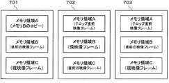
期間502では、テロップT1が存在し、期間501から期間502へ移行する際に、テロップ無しからテロップT1へのテロップチェンジTC1が発生している。期間502の先頭(最初のフレーム)では、テロップ検出部102でテロップ領域が検出され、テロップチェンジ検出部103でテロップの出現が検出される。テロップチェンジTC1時点でのメモリ状態が図6の状態601であったとすると、記録制御部104は、テロップチェンジ検出部103の検出結果に従い、メモリ領域Bに記録されている映像フレーム(すなわち現映像フレームの直前の映像フレーム)をメモリ領域Aにコピーする。これにより、映像記録部101のメモリ状態は、図6の状態601から図7の状態701に遷移する。期間502におけるその後の期間では、テロップ検出部102でテロップ領域が検出され、テロップチェンジ検出部103でテロップチェンジは検出されない。記録制御部104は、現映像フレーム用のメモリ領域と、現映像フレームの直前の映像フレーム用のメモリ領域とを入れ替える制御を行う。これにより、メモリ領域BおよびCには、フレーム毎に交互に映像フレームが保存される。具体的には、映像記録部101の状態は、図7の状態702と状態703とをフレーム毎に交互に繰り返す。状態702では、メモリ領域Bが現映像フレーム用のメモリ領域であり、メモリ領域Cが現映像フレームの直前の映像フレーム用のメモリ領域である。状態703では、メモリ領域Cが現映像フレーム用のメモリ領域であり、メモリ領域Bが現映像フレームの直前の映像フレーム用のメモリ領域である。メモリ領域Aには、テロップT1が出現する直前の映像フレームがそのまま保持される。期間502では、映像処理部105は、現映像フレームのテロップ領域をメモリ領域Aの映像フレームにより置き換え、テロップT1が消去された現映像フレームを出力映像フレームとして出力する。   In the period 502, a telop T1 exists, and when the period 501 is shifted to the period 502, a telop change TC1 from the absence of the telop to the telop T1 occurs. At the beginning (first frame) of the period 502, the telop detection unit 102 detects the telop area, and the telop change detection unit 103 detects the appearance of the telop. If the memory state at the time of the telop change TC1 is the state 601 in FIG. 6, the recording control unit 104 follows the detection result of the telop change detection unit 103, and the video frame recorded in the memory area B (that is, the current video frame). Is copied to the memory area A. As a result, the memory state of the video recording unit 101 transitions from the state 601 in FIG. 6 to the state 701 in FIG. In the subsequent period of the period 502, the telop detection unit 102 detects the telop area, and the telop change detection unit 103 does not detect the telop change. The recording control unit 104 performs control to switch the memory area for the current video frame and the memory area for the video frame immediately before the current video frame. As a result, video frames are stored alternately in the memory areas B and C for each frame. Specifically, the state of the video recording unit 101 repeats the state 702 and the state 703 of FIG. 7 alternately for each frame. In the state 702, the memory area B is a memory area for the current video frame, and the memory area C is a memory area for the video frame immediately before the current video frame. In the state 703, the memory area C is a memory area for the current video frame, and the memory area B is a memory area for the video frame immediately before the current video frame. In the memory area A, the video frame immediately before the appearance of the telop T1 is held as it is. In the period 502, the video processing unit 105 replaces the telop area of the current video frame with the video frame in the memory area A, and outputs the current video frame from which the telop T1 has been deleted as an output video frame.

期間503では、テロップT2が存在し、期間502から期間503へ移行する際に、テロップがテロップT1からテロップT2へ切り替わるテロップチェンジTC2が発生している。期間503では、テロップ検出部102でテロップ領域が検出され、テロップチェンジ検出部103でテロップチェンジは検出されない。記録制御部104は、現映像フレーム用のメモリ領域と、現映像フレームの直前の映像フレーム用のメモリ領域とを入れ替える制御を行う。これにより、映像記録部101の状態は、図7の状態702と状態703とをフレーム毎に交互に繰り返す。メモリ領域Aには、テロップT1が出現する直前の映像フレームがそのまま保持される。期間503では、映像処理部105は、現映像フレームのテロップ領域をメモリ領域Aの映像フレームにより置き換え、テロップT2が消去された現映像フレームを出力映像フレームとして出力する。   In the period 503, a telop T2 exists, and a telop change TC2 in which the telop switches from the telop T1 to the telop T2 occurs when the period 502 shifts to the period 503. In the period 503, the telop detection unit 102 detects the telop area, and the telop change detection unit 103 does not detect the telop change. The recording control unit 104 performs control to switch the memory area for the current video frame and the memory area for the video frame immediately before the current video frame. Thereby, the state of the video recording unit 101 repeats the state 702 and the state 703 of FIG. 7 alternately for each frame. In the memory area A, the video frame immediately before the appearance of the telop T1 is held as it is. In the period 503, the video processing unit 105 replaces the telop area of the current video frame with the video frame in the memory area A, and outputs the current video frame from which the telop T2 is erased as an output video frame.

期間504では、テロップが存在せず、期間503から期間504へ移行する際に、テロップT2からテロップ無しへのテロップチェンジTC3が発生している。期間504の先頭(最初のフレーム)では、テロップ検出部102でテロップが検出されず、テロップチェンジ検出部103でテロップの消滅が検出される。記録制御部104は、テロップチェンジ検出部103の検出結果に従い、メモリ領域Aの内容を空に更新する。これにより、映像記録部101のメモリ状態は、例えば、図7の状態703から図6の状態601に遷移する。期間504におけるその後の期間では、テロップ検出部102でテロップは検出されず、テロップチェンジ検出部103でテロップチェンジは検出されない。記録制御部104は、現映像フレーム用のメモリ領域と、現映像フレームの直前の映像フレーム用のメモリ領域とを入れ替える制御を行う。これにより、メモリ領域BおよびCには、フレーム毎に交互に映像フレームが保存される。具体的には、映像記録部101の状態は、図6の状態601と状態602とをフレーム毎に交互に繰り返す。メモリ領域Aは、空のままである。期間504では、映像処理部105は、置き換えを行わずに、現映像フレームを出力映像フレームとして出力する。   In the period 504, there is no telop, and a telop change TC3 from telop T2 to no telop occurs when the period 503 shifts to the period 504. At the beginning (first frame) of the period 504, the telop detection unit 102 does not detect the telop, and the telop change detection unit 103 detects the disappearance of the telop. The recording control unit 104 updates the contents of the memory area A to empty according to the detection result of the telop change detection unit 103. Thereby, for example, the memory state of the video recording unit 101 changes from the state 703 in FIG. 7 to the state 601 in FIG. 6. In the subsequent period in the period 504, no telop is detected by the telop detection unit 102, and no telop change is detected by the telop change detection unit 103. The recording control unit 104 performs control to switch the memory area for the current video frame and the memory area for the video frame immediately before the current video frame. As a result, video frames are stored alternately in the memory areas B and C for each frame. Specifically, the state of the video recording unit 101 repeats the state 601 and the state 602 in FIG. 6 alternately for each frame. Memory area A remains empty. In the period 504, the video processing unit 105 outputs the current video frame as an output video frame without performing replacement.

図8は、テロップ遷移の別の一例を示す図である。図8には、テロップT1からテロップT2への遷移の間に、テロップがなくなる場合が示されている。以下、図8のようにテロップが遷移する場合における、映像処理装置100の各部の動作およびメモリ状態を説明する。   FIG. 8 is a diagram illustrating another example of telop transition. FIG. 8 shows a case where the telop disappears during the transition from the telop T1 to the telop T2. Hereinafter, the operation and memory state of each part of the video processing apparatus 100 when the telop transitions as shown in FIG. 8 will be described.

期間801では、テロップが存在しない。映像処理装置100の各部の動作およびメモリ状態は、図5の期間501の場合と同様である。   In the period 801, there is no telop. The operation and memory state of each part of the video processing apparatus 100 are the same as those in the period 501 in FIG.

期間802では、テロップT1が存在し、期間801から期間802へ移行する際に、テロップ無しからテロップT1へのテロップチェンジTC11が発生している。映像処理装置100の各部の動作およびメモリ状態は、図5の期間502の場合と同様である。   In the period 802, the telop T1 exists, and when the period 801 shifts to the period 802, a telop change TC11 from no telop to telop T1 occurs. The operation and memory state of each part of the video processing apparatus 100 are the same as those in the period 502 in FIG.

期間803では、テロップが存在せず、期間802から期間803へ移行する際に、テロップT1からテロップ無しへのテロップチェンジTC12が発生している。映像処理装置100の各部の動作およびメモリ状態は、図5の期間504の場合と同様である。   In the period 803, there is no telop, and the telop change TC12 from telop T1 to no telop occurs when the period 802 shifts to the period 803. The operation and memory state of each part of the video processing apparatus 100 are the same as those in the period 504 in FIG.

期間804では、テロップT2が存在し、期間803から期間804へ移行する際に、テロップ無しからテロップT2へのテロップチェンジTC13が発生している。映像処理装置100の各部の動作およびメモリ状態は、図5の期間502の場合と同様である。この場合、映像処理部105は、現映像フレームのテロップ領域を、メモリ領域Aに記録されているテロップT2が出現する直前の映像フレームにより置き換え、テロップT2が消去された現映像フレームを出力映像フレームとして出力する。   In the period 804, a telop T2 exists, and a telop change TC13 from no telop to telop T2 occurs when the period 803 shifts to the period 804. The operation and memory state of each part of the video processing apparatus 100 are the same as those in the period 502 in FIG. In this case, the video processing unit 105 replaces the telop area of the current video frame with the video frame immediately before the appearance of the telop T2 recorded in the memory area A, and the current video frame from which the telop T2 has been deleted is output video frame. Output as.

期間805では、テロップが存在せず、期間804から期間805へ移行する際に、テロップT2からテロップ無しへのテロップチェンジTC14が発生している。映像処理装置100の各部の動作およびメモリ状態は、図5の期間504の場合と同様である。   In the period 805, there is no telop, and when the transition from the period 804 to the period 805 occurs, a telop change TC14 from telop T2 to no telop has occurred. The operation and memory state of each part of the video processing apparatus 100 are the same as those in the period 504 in FIG.

以上説明した本実施の形態1によれば、下記(1)〜(3)の効果が得られ得る。
(1)本実施の形態では、映像処理装置は、映像フレームのテロップ領域を、当該テロップ領域のテロップが出現する前の映像フレームから得られる画像に置き換える。このため、本実施の形態によれば、映像フレームに含まれるテロップ領域を1種類の映像信号から置き換えることができる。具体的には、テロップ領域を1種類の映像信号のみでも正しくまたは違和感なく置き換えることができ、テロップの消去された(またはテロップのない)良好な映像フレームを生成または表示することができる。一方、特許文献1に記載された技術のように、映像信号に含まれるテロップを当該映像信号とは別の種類の映像信号を用いて消去する構成では、別の種類の映像信号が存在しない場合、テロップを消去することができない。例えば、2008年3月末まで、一つの放送局から12セグメント放送とワンセグ放送とで同一番組を流すサイマル放送が義務付けられていたが、現在では、その義務はなく、一部の放送でサイマル放送が実施されていない。つまり、別の種類の映像信号が存在しない場合がある。
According to the first embodiment described above, the following effects (1) to (3) can be obtained.
(1) In this embodiment, the video processing device replaces the telop area of the video frame with an image obtained from the video frame before the telop in the telop area appears. Therefore, according to the present embodiment, the telop area included in the video frame can be replaced with one type of video signal. Specifically, the telop area can be replaced correctly or comfortably with only one type of video signal, and a good video frame from which the telop has been erased (or without the telop) can be generated or displayed. On the other hand, when a telop included in a video signal is erased using a video signal of a different type from the video signal as in the technique described in Patent Document 1, there is no other type of video signal. The telop cannot be erased. For example, until the end of March 2008, it was obliged to run a simulcast that broadcasts the same program in 12-segment broadcasting and one-segment broadcasting from one broadcasting station. Not implemented. That is, another type of video signal may not exist.

(2)映像処理装置は、一連の映像フレームからテロップの出現を検出し、この検出結果に基づき、上記一連の映像フレームのうち上記テロップが出現する前の映像フレームを記録する。本態様によれば、テロップ領域の置き換えに用いる映像フレームを選択的に記録することができる。   (2) The video processing device detects the appearance of a telop from a series of video frames, and records the video frame before the telop appears in the series of video frames based on the detection result. According to this aspect, it is possible to selectively record a video frame used for replacing a telop area.

(3)映像処理装置は、一連の映像フレームが順次入力され、現映像フレームとその前の映像フレームとを記録する映像記録部を備え、記録された現映像フレームについてテロップ領域の検出およびテロップの出現の検出を行う。そして、テロップの出現が検出された場合に、記録された現映像フレームの前の映像フレームを、テロップが出現する前の映像フレームとして記録する。また、テロップ領域が検出された場合に、現映像フレームのテロップ領域を、記録されたテロップが出現する前の映像フレームから得られる画像に置き換え、テロップ領域が置き換えられた現映像フレームを出力する。本態様によれば、順次入力される映像フレームを順次処理することができる。   (3) The video processing apparatus includes a video recording unit that sequentially inputs a series of video frames and records the current video frame and the previous video frame, and detects a telop area and detects a telop for the recorded current video frame. Appearance detection. Then, when the appearance of the telop is detected, the video frame before the recorded current video frame is recorded as the video frame before the telop appears. When the telop area is detected, the telop area of the current video frame is replaced with an image obtained from the video frame before the recorded telop appears, and the current video frame with the telop area replaced is output. According to this aspect, it is possible to sequentially process sequentially input video frames.

実施の形態2.
図9は、実施の形態2に係る映像処理装置900の構成を示すブロック図である。この映像処理装置900は、実施の形態1に係る映像処理装置100に対し、テロップチェンジの検出結果に応じてテロップ置換方法を切り替える点で異なっており、その他の部分については略同様である。以下の説明では、実施の形態1と同様の部分については説明を省略または簡略化し、実施の形態1と同一または対応する要素については同一の符号を付す。
Embodiment 2. FIG.
FIG. 9 is a block diagram showing the configuration of the video processing apparatus 900 according to the second embodiment. The video processing apparatus 900 is different from the video processing apparatus 100 according to Embodiment 1 in that the telop replacement method is switched according to the detection result of the telop change, and the other parts are substantially the same. In the following description, the description of the same parts as those in the first embodiment is omitted or simplified, and the same or corresponding elements as those in the first embodiment are denoted by the same reference numerals.

テロップチェンジ検出部103は、入力される一連の映像フレームからテロップの出現およびテロップの切り替わりをテロップチェンジとして検出する。一つの態様では、テロップチェンジ検出部103は、テロップを構成する文字(テロップ文字)のエッジおよび当該文字の輪郭部のエッジを検出し、検出されるエッジの変化に基づいてテロップの切り替わりを検出する。具体的には、テロップチェンジ検出部103は、現映像フレームの直前の映像フレームにおけるテロップ領域内の文字および輪郭部のエッジを検出し、現映像フレームにおけるテロップ領域内の文字および輪郭部のエッジを検出し、両映像フレーム間のエッジの変化が所定レベル以上であれば、テロップの切り替わりが発生したと判定し、そうでなければ、テロップの切り替わりは発生していないと判定する。   The telop change detection unit 103 detects the appearance of a telop and the change of the telop as a telop change from a series of input video frames. In one aspect, the telop change detection unit 103 detects the edge of the character (telop character) constituting the telop and the edge of the outline of the character, and detects the switching of the telop based on the detected edge change. . Specifically, the telop change detection unit 103 detects characters and edges in the telop area in the video frame immediately before the current video frame, and detects characters and edges in the telop area in the current video frame. If it is detected and the edge change between both video frames is equal to or higher than a predetermined level, it is determined that a telop switching has occurred. Otherwise, it is determined that no telop switching has occurred.

テロップチェンジ検出部103は、テロップチェンジとして、さらにテロップの消滅を検出してもよい。   The telop change detection unit 103 may further detect the disappearance of the telop as the telop change.

本例では、テロップチェンジ検出部103は、テロップチェンジの検出を行い、その検出結果を示すフラグを出力する。図10には、テロップチェンジ検出部103から出力されるフラグの一覧が示されている。具体的には、テロップチェンジ検出部103は、テロップ検出部102の検出結果に基づき、以下のようにテロップチェンジの検出を行う。   In this example, the telop change detection unit 103 detects a telop change and outputs a flag indicating the detection result. FIG. 10 shows a list of flags output from the telop change detection unit 103. Specifically, the telop change detection unit 103 detects the telop change based on the detection result of the telop detection unit 102 as follows.

現映像フレームの直前の映像フレームにテロップが無く、現映像フレームにもテロップが無い場合には、テロップもテロップチェンジも無いことを示す「テロップ無」フラグを出力する。   When there is no telop in the video frame immediately before the current video frame and there is no telop in the current video frame, a “no telop” flag indicating that there is no telop or telop change is output.

現映像フレームの直前の映像フレームにテロップが無く、現映像フレームにテロップが有る場合には、テロップ無しから有りへの変化(テロップの出現)を示す「無→有」フラグを出力する。   If there is no telop in the video frame immediately before the current video frame and there is a telop in the current video frame, an “none → present” flag indicating a change from the absence of telop to the presence (appearance of telop) is output.

現映像フレームの直前の映像フレームにテロップが有り、現映像フレームにテロップが無い場合には、テロップ有りから無しへの変化(テロップの消滅)を示す「有→無」フラグを出力する。   If the video frame immediately before the current video frame has a telop and the current video frame does not have a telop, a “presence → non-exist” flag indicating a change from the presence of the telop to the absence (telop disappearance) is output.

現映像フレームの直前の映像フレームにテロップが有り、現映像フレームにもテロップが有る場合には、テロップの切り替わりを判定し、テロップが切り替わったと判定されたときには、テロップ有りから別のテロップへの変化(テロップの切り替わり)を示す「有→有」フラグを出力する。一方、テロップが切り替わっていないと判定されたときには、テロップは有るがテロップチェンジは無いことを示す「テロップ有」フラグを出力する。   If there is a telop in the video frame immediately before the current video frame, and there is also a telop in the current video frame, it is determined whether the telop has been switched. A “present → present” flag indicating (telop switching) is output. On the other hand, when it is determined that the telop has not been switched, a “telop present” flag indicating that there is a telop but no telop change is output.

以下、図11を参照して、上記テロップの切り替わりの判定の一例を示す。図11には、映像フレームにより表される映像全体の領域1101と、当該領域1101に含まれるテロップ領域1102と、当該テロップ領域1102に含まれるテロップ1103とが示されている。   Hereinafter, with reference to FIG. 11, an example of the determination of switching of the telop will be shown. FIG. 11 shows a region 1101 of the entire video represented by the video frame, a telop region 1102 included in the region 1101, and a telop 1103 included in the telop region 1102.

テロップ領域1102は、テロップ検出部102により検出されたものである。簡単のため、テロップ領域1102のうちテロップ1103以外の領域の各画素の輝度値は、同じ輝度値kcであるとする。   The telop area 1102 is detected by the telop detection unit 102. For simplicity, it is assumed that the luminance value of each pixel in the area other than the telop 1103 in the telop area 1102 is the same luminance value kc.

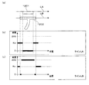
一般的に、テロップは、図12(a)に示されるように、一定の文字色を有する文字1201と、一定の輪郭色を有する文字の輪郭部1202とを含む。ここでは、輝度値が8bitの整数値(0〜255)で表され、文字色が白(輝度値255)であり、輪郭色が黒(輝度値0)であるとする。   In general, as shown in FIG. 12A, a telop includes a character 1201 having a certain character color and a character outline 1202 having a certain contour color. Here, it is assumed that the luminance value is represented by an 8-bit integer value (0 to 255), the character color is white (luminance value 255), and the outline color is black (luminance value 0).

図12(b)は、図12(a)のラインLA(テロップ文字「テ」の最上部の輪郭部を通るライン)における輝度分布を示す。図12(c)は、図12(a)のラインLB(テロップ文字「テ」の中心部を通るライン)における輝度分布を示す。   FIG. 12B shows a luminance distribution in the line LA (line passing through the uppermost contour portion of the telop character “te”) in FIG. FIG. 12C shows a luminance distribution in the line LB (a line passing through the center of the telop character “te”) in FIG.

図12(b)では、背景色(輝度値kc)、輪郭色(輝度値0)、背景色(輝度値kc)の順に変化しており、輝度値の急峻なエッジが2箇所存在する。図12(c)では、背景色(輝度値kc)、数画素の輪郭部の輪郭色(輝度値0)、文字色(輝度値255)、数画素の輪郭部の輪郭色(輝度値0)、背景色(輝度値kc)の順に変化しており、輝度値の急峻なエッジが4箇所存在する。   In FIG. 12B, the background color (luminance value kc), the contour color (luminance value 0), and the background color (luminance value kc) are changed in this order, and there are two sharp edges of the luminance value. In FIG. 12 (c), the background color (luminance value kc), the contour color of several pixel contours (luminance value 0), the character color (luminance value 255), and the contour color of several pixel contours (luminance value 0). The background color (luminance value kc) changes in this order, and there are four sharp edges of the luminance value.

テロップチェンジ検出部103は、映像フレームの全体またはテロップ領域に対して、水平方向および垂直方向について、上記のようなエッジの検出を行い、この検出結果に基づいてテロップの切り替わりを検出する。テロップが切り替わった場合は、エッジの個数や位置が変化することから、一つの態様では、テロップチェンジ検出部103は、検出されたエッジの個数や位置の情報を基にテロップの切り替わりを検出する。例えば、テロップチェンジ検出部103は、図11のテロップ領域1102の左上端位置の座標を(0,0)として、検出された各エッジを2次元ベクトルで表し、それぞれのベクトルの大きさの和を求め、この和の大きさの変化によりテロップチェンジを判定する。また例えば、テロップチェンジ検出部103は、検出されたエッジ座標の個数の差分によってテロップチェンジを判定してもよい。なお、上記エッジの検出は、水平方向のみ、または垂直方向のみについて実施されてもよい。   The telop change detection unit 103 detects the edge as described above in the horizontal direction and the vertical direction with respect to the entire video frame or the telop area, and detects the switching of the telop based on the detection result. When the telop is switched, the number and position of the edges change. In one aspect, the telop change detection unit 103 detects the switching of the telop based on the detected information on the number and position of the edges. For example, the telop change detection unit 103 represents each detected edge as a two-dimensional vector with the coordinates of the upper left end position of the telop area 1102 in FIG. 11 as (0, 0), and the sum of the sizes of the vectors The telop change is determined based on the change in the sum. For example, the telop change detection unit 103 may determine the telop change based on the difference in the number of detected edge coordinates. The edge detection may be performed only in the horizontal direction or only in the vertical direction.

上記テロップのエッジの検出において、テロップチェンジ検出部103は、例えば、互いに隣接する2つの画素の輝度値の差分の絶対値dが所定の閾値kd以上である場合に、すなわちd≧kdが満たされる場合に、両画素間にエッジが存在すると判定する。テロップチェンジ検出部103は、輝度値のみでなく、色情報を用いてエッジを検出してもよい。例えば、画素の情報が輝度信号Yと色差信号(Cb,Cr)とで表される場合、それらを3次元のベクトルとみなし、互いに隣接する2つの画素間の画素情報のベクトルの大きさの差分の絶対値を用いてエッジを検出してもよい。   In the detection of the telop edge, the telop change detection unit 103 satisfies, for example, d ≧ kd when the absolute value d of the difference between the luminance values of two adjacent pixels is equal to or greater than a predetermined threshold kd. In this case, it is determined that an edge exists between both pixels. The telop change detection unit 103 may detect edges using color information as well as luminance values. For example, when pixel information is represented by a luminance signal Y and a color difference signal (Cb, Cr), they are regarded as a three-dimensional vector, and the difference in the size of the pixel information vector between two adjacent pixels is considered. The edge may be detected using the absolute value of.

なお、上記テロップの切り替わりの判定方法は一例であり、現映像フレームと現映像フレームの直前の映像フレームとの間でのテロップの切り替わりを検出することができれば、別の方法が用いられてもよい。   Note that the above telop switching determination method is merely an example, and another method may be used as long as the telop switching between the current video frame and the video frame immediately before the current video frame can be detected. .

また、上記の説明では、テロップ検出部102の検出結果を用いてテロップチェンジ(出現、消滅、および切り替わり)を検出する構成を例示したが、テロップチェンジ検出部103は、別の方法でテロップチェンジを検出してもよい。例えば、テロップチェンジ検出部103は、映像記録部101から現映像フレームと現映像フレームの直前の映像フレームとを読み出し、両映像フレームを比較してテロップチェンジ(出現、消滅、および切り替わり)を検出してもよい。この場合、テロップチェンジ検出部103は、例えば、上述のエッジ検出方法により、テロップを構成する文字のエッジおよび当該文字の輪郭部のエッジを検出し、検出されるエッジの変化に基づいてテロップチェンジを検出する。なお、テロップチェンジ検出部103は、1フレーム分の映像信号からテロップチェンジを検出してもよいし、テロップ検出部102の検出結果に基づき、テロップ領域の映像信号からテロップチェンジを検出してもよい。   Further, in the above description, the configuration in which the telop change (appearance, disappearance, and switching) is detected using the detection result of the telop detection unit 102 is illustrated, but the telop change detection unit 103 performs the telop change by another method. It may be detected. For example, the telop change detection unit 103 reads the current video frame and the video frame immediately before the current video frame from the video recording unit 101, compares the two video frames, and detects a telop change (appearance, disappearance, and switching). May be. In this case, the telop change detection unit 103 detects, for example, the edge of the character constituting the telop and the edge of the outline of the character by the above-described edge detection method, and performs the telop change based on the detected edge change. To detect. The telop change detection unit 103 may detect a telop change from the video signal for one frame, or may detect a telop change from the video signal in the telop area based on the detection result of the telop detection unit 102. .

映像処理部105は、テロップ領域が検出された映像フレームにおけるテロップ領域を置き換える場合、テロップチェンジ検出部103の検出結果に基づき、置換対象の映像フレームの直前のテロップチェンジがテロップの出現であるときには、テロップ領域のテロップが出現する前の映像フレームから得られる画像に置き換え、置換対象の映像フレームの直前のテロップチェンジがテロップの切り替わりであるときには、置換対象の映像フレームのテロップ領域の周辺画素から得られる画像に置き換える。すなわち、映像処理部105は、テロップ領域が検出された映像フレームにおけるテロップ領域を補間する場合、テロップチェンジ検出部103の検出結果に基づき、補間対象の映像フレームの直前のテロップチェンジがテロップの出現であるときには、テロップ領域のテロップが出現する前の映像フレームから補間し、補間対象の映像フレームの直前のテロップチェンジがテロップの切り替わりであるときには、補間対象の映像フレームのテロップ領域の周辺画素から補間する。   When replacing the telop area in the video frame in which the telop area is detected, the video processing unit 105, based on the detection result of the telop change detection unit 103, when the telop change immediately before the replacement target video frame is the appearance of the telop, Replaced with the image obtained from the video frame before the appearance of the telop in the telop area, and obtained from the surrounding pixels of the telop area of the replacement target video frame when the telop change immediately before the replacement target video frame is a telop change Replace with an image. That is, when the video processing unit 105 interpolates the telop area in the video frame in which the telop area is detected, based on the detection result of the telop change detection unit 103, the telop change immediately before the video frame to be interpolated is the appearance of the telop. In some cases, interpolation is performed from the video frame before the appearance of the telop in the telop area, and when the telop change immediately before the video frame to be interpolated is telop switching, interpolation is performed from surrounding pixels in the telop area of the video frame to be interpolated. .

以下、図13および図14を参照して、テロップ領域をその周辺画素から得られる画像に置き換える方法の一例を示す。図13には、テロップ1301を含むテロップ領域1302と、当該テロップ領域1302の外側領域1303とが示されている。外側領域1303は、テロップ領域1302に対して水平方向および垂直方向に隣接する画素により構成されている。   Hereinafter, an example of a method for replacing a telop area with an image obtained from its peripheral pixels will be described with reference to FIGS. 13 and 14. FIG. 13 shows a telop area 1302 including the telop 1301 and an outer area 1303 of the telop area 1302. The outer area 1303 includes pixels adjacent to the telop area 1302 in the horizontal direction and the vertical direction.

映像処理部105は、テロップ領域1302内の画素の画素値を、外側領域1303の画素(テロップ領域1302の外側の画素)の画素値から得られる画素値に置き換える。例えば、図14に示されるように、映像処理部105は、テロップ領域1302内の画素PIの置換後の画素値を求める場合、外側領域1303の画素のうち、置換対象の画素PIに対して上下左右に位置する4個の画素PA,PB,PC,PDの画素値の平均値を求める。例えば、画素がRGB三原色の画素値(R,G,B)で表される場合、映像処理部105は、下記式(1)により、画素PAの画素値(R,G,B)、画素PBの画素値(R,G,B)、画素PCの画素値(R,G,B)、画素PDの画素値(R,G,B)から、置換対象の画素PIの画素値(R,G,B)を求める。なお、各色の画素値は、例えば8bit(0〜255)で表される。

Figure 2013179563
なお、映像処理部105は、より簡単に、水平方向の2つの画素(すなわち画素PBと画素PC)の画素値の平均、または垂直方向の2つの画素(すなわち画素PAと画素PD)の画素値の平均を、画素PIの置換後の画素値として求めてもよい。 The video processing unit 105 replaces the pixel value of the pixel in the telop area 1302 with a pixel value obtained from the pixel value of the pixel in the outer area 1303 (the pixel outside the telop area 1302). For example, as illustrated in FIG. 14, when obtaining the pixel value after replacement of the pixel PI in the telop area 1302, the video processing unit 105 moves up and down with respect to the pixel PI to be replaced among the pixels in the outer area 1303. The average value of the pixel values of the four pixels PA, PB, PC, and PD located on the left and right is obtained. For example, when a pixel is represented by pixel values (R, G, B) of RGB three primary colors, the video processing unit 105 uses the following formula (1) to calculate the pixel value (R A , G A , B A ) of the pixel PA. From the pixel value (R B , G B , B B ) of the pixel PB, the pixel value (R C , G C , B C ) of the pixel PC, and the pixel value (R D , G D , B D ) of the pixel PD, The pixel value (R I , G I , B I ) of the pixel PI to be replaced is obtained. In addition, the pixel value of each color is represented by 8 bits (0-255), for example.
Figure 2013179563
Note that the video processing unit 105 can more easily calculate the average of the pixel values of the two pixels in the horizontal direction (that is, the pixel PB and the pixel PC) or the pixel value of the two pixels in the vertical direction (that is, the pixel PA and the pixel PD). May be obtained as the pixel value after replacement of the pixel PI.

以下、図4を参照して、実施の形態2に係る映像処理装置900の動作について説明する。映像処理装置900の動作は、図4に示される実施の形態1に係る映像処理装置100の動作と略同様である。   Hereinafter, the operation of the video processing apparatus 900 according to the second embodiment will be described with reference to FIG. The operation of the video processing apparatus 900 is substantially the same as the operation of the video processing apparatus 100 according to Embodiment 1 shown in FIG.

ただし、本実施の形態では、ステップS403において、映像処理装置900は、テロップチェンジとして、テロップの出現および消滅の他に、テロップの切り替わりを検出する。   However, in the present embodiment, in step S403, the video processing apparatus 900 detects telop switching as well as telop appearance and disappearance as telop changes.

また、ステップS405では、映像処理装置900は、ステップS403でテロップの出現または切り替わりが検出されたか否かを判定し、検出された場合には(S405:YES)、ステップS406へ進み、検出されなかった場合には(S405:NO)、ステップS407へ進む。具体的には、図15に示されるように、ステップS403でテロップチェンジ検出部103から出力されるフラグが「無→有」フラグまたは「有→有」フラグである場合には、ステップS405の判定結果は「YES」となり、「テロップ有」フラグである場合には、ステップS405の判定結果は「NO」となる。   In step S405, the video processing apparatus 900 determines whether the appearance or switching of the telop is detected in step S403. If it is detected (S405: YES), the process proceeds to step S406 and is not detected. If YES in step S405, the process proceeds to step S407. Specifically, as shown in FIG. 15, when the flag output from the telop change detection unit 103 in step S403 is an “none → present” flag or an “present → present” flag, the determination in step S405 is performed. The result is “YES”, and if the flag is “telop present”, the determination result in step S405 is “NO”.

また、ステップS407では、映像処理装置900は、今回以前のステップS403のテロップチェンジの検出結果に基づき、直前のテロップチェンジに応じた置換方法でテロップ領域の置き換えを行う。具体的には、現映像フレームの直前のテロップチェンジがテロップの出現であるときには、実施の形態1と同様に、映像処理装置900は、現映像フレームのテロップ領域を、メモリ領域Aに記録されているテロップが出現する直前の映像フレームから得られる画像に置き換える。一方、現映像フレームの直前のテロップチェンジがテロップの切り替わりであるときには、現映像フレームのテロップ領域を、現映像フレームのテロップ領域の周辺画素から得られる画像に置き換える。   In step S407, the video processing apparatus 900 replaces the telop area by a replacement method corresponding to the previous telop change based on the detection result of the telop change in step S403 before this time. Specifically, when the telop change immediately before the current video frame is the appearance of a telop, the video processing apparatus 900 records the telop area of the current video frame in the memory area A as in the first embodiment. Replace with the image obtained from the video frame immediately before the telop appears. On the other hand, when the telop change immediately before the current video frame is a telop change, the telop area of the current video frame is replaced with an image obtained from the peripheral pixels of the telop area of the current video frame.

以下、図5のようにテロップが遷移する場合における、映像処理装置900の各部の動作およびメモリ状態を説明する。   Hereinafter, the operation and memory state of each part of the video processing apparatus 900 when the telop transitions as shown in FIG. 5 will be described.

期間501では、映像処理装置900の各部の動作およびメモリ状態は、実施の形態1に係る映像処理装置100と同様であり、映像記録部101の状態は、図6の状態601と状態602とをフレーム毎に交互に繰り返し、メモリ領域Aは空である。このようにメモリ領域Aが空のときの映像記録部101の状態をメモリ状態aと呼ぶ。   In the period 501, the operation and memory state of each unit of the video processing apparatus 900 are the same as those of the video processing apparatus 100 according to Embodiment 1, and the state of the video recording unit 101 is the state 601 and the state 602 in FIG. The memory area A is empty by repeating alternately every frame. The state of the video recording unit 101 when the memory area A is empty is called a memory state a.

期間502の先頭では、テロップ検出部102でテロップ領域が検出され、テロップチェンジ検出部103でテロップの出現が検出され、「無→有」フラグが出力される。テロップチェンジTC1時点でのメモリ状態が図6の状態601であったとすると、記録制御部104は、テロップチェンジ検出部103の検出結果に従い、メモリ領域Bに記録されている映像フレーム(すなわち現映像フレームの直前の映像フレーム)をメモリ領域Aにコピーする。これにより、映像記録部101の状態は、図6の状態601から図7の状態701に遷移する。期間502におけるその後の期間では、テロップ検出部102でテロップ領域が検出され、テロップチェンジ検出部103でテロップチェンジは検出されず、「テロップ有」フラグが出力される。映像記録部101の状態は、図7の状態702と状態703とをフレーム毎に交互に繰り返し、メモリ領域Aには、テロップT1が出現する直前の映像フレームがそのまま保持される。このようにメモリ領域Aにテロップが出現する直前の映像フレームが保存されているときの映像記録部101の状態をメモリ状態bと呼ぶ。期間502では、映像処理部105は、現映像フレームのテロップ領域をメモリ領域Aの映像フレームにより置き換え、テロップT1が消去された現映像フレームを出力映像フレームとして出力する。   At the beginning of the period 502, the telop detection unit 102 detects the telop area, the telop change detection unit 103 detects the appearance of the telop, and the “No → Yes” flag is output. If the memory state at the time of the telop change TC1 is the state 601 in FIG. 6, the recording control unit 104 follows the detection result of the telop change detection unit 103, and the video frame recorded in the memory area B (that is, the current video frame). Is copied to the memory area A. As a result, the state of the video recording unit 101 transitions from the state 601 in FIG. 6 to the state 701 in FIG. In the subsequent period of the period 502, a telop area is detected by the telop detection unit 102, a telop change is not detected by the telop change detection unit 103, and a “telop present” flag is output. As the state of the video recording unit 101, the state 702 and the state 703 of FIG. 7 are alternately repeated for each frame, and the memory region A holds the video frame immediately before the appearance of the telop T1 as it is. Thus, the state of the video recording unit 101 when the video frame immediately before the appearance of the telop is stored in the memory area A is referred to as a memory state b. In the period 502, the video processing unit 105 replaces the telop area of the current video frame with the video frame in the memory area A, and outputs the current video frame from which the telop T1 has been deleted as an output video frame.

期間503の先頭では、テロップ検出部102でテロップ領域が検出され、テロップチェンジ検出部103でテロップの切り替わりが検出され、「有→有」フラグが出力される。記録制御部104は、テロップチェンジ検出部103の検出結果に従い、メモリ領域Aの内容をメモリ領域Bの内容(テロップが切り替わる直前の映像フレーム)に更新する。期間503におけるその後の期間では、テロップ検出部102でテロップ領域が検出され、テロップチェンジ検出部103でテロップチェンジは検出されず、「テロップ有」フラグが出力される。映像記録部101の状態は、図7の状態702と状態703とをフレーム毎に交互に繰り返し、メモリ領域Aには、テロップがテロップT2に切り替わる直前の映像フレームがそのまま保持される。このようにメモリ領域Aにテロップの切り替わり直前の映像フレームが保存されているときの映像記録部101の状態をメモリ状態cと呼ぶ。期間503では、映像処理部105は、現映像フレームのテロップ領域を当該テロップ領域の周辺画素により置き換え、テロップT2が消去された現映像フレームを出力映像フレームとして出力する。   At the beginning of the period 503, the telop detection unit 102 detects a telop area, the telop change detection unit 103 detects a telop switching, and a “present → present” flag is output. The recording control unit 104 updates the contents of the memory area A to the contents of the memory area B (the video frame immediately before the telop is switched) according to the detection result of the telop change detection unit 103. In the subsequent period in the period 503, the telop detection unit 102 detects the telop area, the telop change detection unit 103 does not detect the telop change, and the “telop present” flag is output. As the state of the video recording unit 101, the state 702 and the state 703 of FIG. 7 are alternately repeated for each frame, and the memory frame A holds the video frame immediately before the telop is switched to the telop T2. Thus, the state of the video recording unit 101 when the video frame immediately before the telop switching is stored in the memory area A is referred to as a memory state c. In the period 503, the video processing unit 105 replaces the telop area of the current video frame with the peripheral pixels of the telop area, and outputs the current video frame from which the telop T2 is erased as an output video frame.

期間504の先頭では、テロップ検出部102でテロップが検出されず、テロップチェンジ検出部103でテロップの消滅が検出され、「有→無」フラグが出力される。記録制御部104は、テロップチェンジ検出部103の検出結果に従い、メモリ領域Aの内容を空に更新する。期間504におけるその後の期間では、テロップ検出部102でテロップは検出されず、テロップチェンジ検出部103でテロップチェンジは検出されず、「テロップ無」フラグが出力される。映像記録部101の状態は、図6の状態601と状態602とをフレーム毎に交互に繰り返し、メモリ領域Aは空のままである。すなわち、期間504における映像記録部101の状態はメモリ状態aである。期間504では、映像処理部105は、置き換えを行わずに、現映像フレームを出力映像フレームとして出力する。   At the beginning of the period 504, no telop is detected by the telop detection unit 102, the disappearance of the telop is detected by the telop change detection unit 103, and a “present → no” flag is output. The recording control unit 104 updates the contents of the memory area A to empty according to the detection result of the telop change detection unit 103. In the subsequent period of the period 504, no telop is detected by the telop detection unit 102, no telop change is detected by the telop change detection unit 103, and a “no telop” flag is output. As for the state of the video recording unit 101, the state 601 and the state 602 of FIG. 6 are alternately repeated for each frame, and the memory area A remains empty. That is, the state of the video recording unit 101 in the period 504 is the memory state a. In the period 504, the video processing unit 105 outputs the current video frame as an output video frame without performing replacement.

以上のように、映像記録部101の状態には、メモリ状態a、メモリ状態b、およびメモリ状態cの3通りの状態が存在する。映像処理装置900は、映像記録部101の状態(メモリ状態a,b,cの何れか)を示す情報を保持しておき、当該情報に基づいて置換方法を決定してもよい。例えば、映像処理装置900は、図4のステップS407において、メモリ状態bの場合には、テロップが出現する直前の映像フレームによる置換を採用し、メモリ状態cの場合には、テロップ領域の周辺画素による置換を採用してもよい。   As described above, there are three states of the video recording unit 101: the memory state a, the memory state b, and the memory state c. The video processing apparatus 900 may store information indicating the state of the video recording unit 101 (any one of the memory states a, b, and c) and determine a replacement method based on the information. For example, in step S407 of FIG. 4, the video processing apparatus 900 employs replacement with a video frame immediately before the appearance of the telop in the memory state b, and in the memory state c, the peripheral pixels in the telop area. Substitution by may be employed.

なお、図8のようにテロップが遷移する場合における、映像処理装置900の各部の動作およびメモリ状態は、実施の形態1に係る映像処理装置100と同様である。   Note that the operation and memory state of each part of the video processing apparatus 900 when the telop transitions as shown in FIG. 8 is the same as that of the video processing apparatus 100 according to the first embodiment.

以上説明した本実施の形態2によれば、上記(1)〜(3)の効果の他に、下記(4)の効果が得られ得る。
(4)本実施の形態では、映像処理装置は、一連の映像フレームからテロップの出現および切り替わりをテロップチェンジとして検出し、映像フレームのテロップ領域を置き換える場合、置換対象の映像フレームの直前のテロップチェンジがテロップの出現であるときには、テロップ領域のテロップが出現する前の映像フレームから得られる画像に置き換え、置換対象の映像フレームの直前のテロップチェンジがテロップの切り替わりであるときには、置換対象の映像フレームのテロップ領域の周辺画素から得られる画像に置き換える。本実施の形態によれば、直前のテロップチェンジに応じた置換方法でテロップ領域を置き換えることができる。
According to the second embodiment described above, the following effect (4) can be obtained in addition to the effects (1) to (3).
(4) In the present embodiment, the video processing device detects the appearance and switching of a telop from a series of video frames as a telop change, and when replacing the telop area of the video frame, the telop change immediately before the video frame to be replaced Is an image obtained from the video frame before the appearance of the telop in the telop area, and when the telop change immediately before the video frame to be replaced is a telop change, Replace with the image obtained from the peripheral pixels of the telop area. According to the present embodiment, the telop area can be replaced by a replacement method corresponding to the immediately preceding telop change.

実施の形態3.
図16は、実施の形態3に係る映像処理装置1600の構成を示すブロック図である。この映像処理装置1600は、実施の形態1に係る映像処理装置100に対し、シーンチェンジの検出結果に応じてテロップ置換方法を切り替える点で異なっており、その他の部分については略同様である。以下の説明では、実施の形態1と同様の部分については説明を省略または簡略化し、実施の形態1と同一または対応する要素については同一の符号を付す。
Embodiment 3 FIG.
FIG. 16 is a block diagram showing a configuration of a video processing apparatus 1600 according to the third embodiment. This video processing apparatus 1600 differs from the video processing apparatus 100 according to Embodiment 1 in that the telop replacement method is switched according to the detection result of the scene change, and the other parts are substantially the same. In the following description, the description of the same parts as those in the first embodiment is omitted or simplified, and the same or corresponding elements as those in the first embodiment are denoted by the same reference numerals.

図16に示されるように、映像処理装置1600は、シーンチェンジ検出部1601をさらに備える。シーンチェンジ検出部1601は、映像処理装置1600に入力される一連の映像フレームからシーンチェンジを検出する。具体的には、シーンチェンジ検出部1601は、一連の映像フレームにより表される映像のシーンの変化を検出する。例えば、シーンチェンジ検出部1601は、映像記録部101から現映像フレームと現映像信号の直前の映像フレームとを読み出し、両映像フレームを比較してシーンチェンジを検出する。このシーンチェンジの検出については、公知のシーンチェンジ検出技術を用いることができ、ここでは詳しい説明を省略する。   As shown in FIG. 16, the video processing device 1600 further includes a scene change detection unit 1601. The scene change detection unit 1601 detects a scene change from a series of video frames input to the video processing device 1600. Specifically, the scene change detection unit 1601 detects a change in the scene of a video represented by a series of video frames. For example, the scene change detection unit 1601 reads the current video frame and the video frame immediately before the current video signal from the video recording unit 101, and compares the two video frames to detect a scene change. For this scene change detection, a known scene change detection technique can be used, and detailed description thereof is omitted here.

映像処理部105は、テロップ領域が検出された映像フレームにおけるテロップ領域を置き換える場合、シーンチェンジ検出部1601の検出結果に基づき、テロップ領域のテロップが出現する前の映像フレームと置換対象の映像フレームとの間でシーンチェンジが発生していないときには、テロップ領域のテロップが出現する前の映像フレームから得られる画像に置き換え、上記両映像フレーム間でシーンチェンジが発生しているときには、置換対象の映像フレームのテロップ領域の周辺画素から得られる画像に置き換える。すなわち、映像処理部105は、テロップ領域が検出された映像フレームにおけるテロップ領域を補間する場合、テロップ領域のテロップが出現する前の映像フレームと補間対象の映像フレームとの間でシーンチェンジが発生していないときには、テロップ領域のテロップが出現する前の映像フレームから補間し、上記両映像フレーム間でシーンチェンジが発生しているときには、補間対象の映像フレームのテロップ領域の周辺画素から補間する。   When replacing the telop area in the video frame in which the telop area is detected, the video processing unit 105, based on the detection result of the scene change detection unit 1601, the video frame before the appearance of the telop in the telop area and the video frame to be replaced When no scene change occurs between the two video frames, the image is replaced with an image obtained from the video frame before the telop in the telop area appears. When a scene change occurs between the two video frames, the video frame to be replaced Is replaced with an image obtained from the peripheral pixels of the telop area. That is, when the video processing unit 105 interpolates the telop area in the video frame in which the telop area is detected, a scene change occurs between the video frame before the appearance of the telop in the telop area and the video frame to be interpolated. If not, interpolation is performed from the video frame before the appearance of the telop in the telop area, and when a scene change occurs between the two video frames, interpolation is performed from peripheral pixels in the telop area of the video frame to be interpolated.

図17は、実施の形態3に係る映像処理装置1600の動作を示すフローチャートである。以下、図17を参照して、映像処理装置1600の動作について説明する。   FIG. 17 is a flowchart showing the operation of the video processing apparatus 1600 according to the third embodiment. Hereinafter, the operation of the video processing apparatus 1600 will be described with reference to FIG.

映像処理装置1600は、ステップS404の前に、現映像フレーム用のメモリ領域に記録された現映像フレームについて、シーンチェンジの検出を行う(S1701)。具体的には、映像処理装置1600は、現映像フレームの直前の映像フレームと現映像フレームとの間でシーンチェンジが発生しているか否かを判定する。   Prior to step S404, the video processing apparatus 1600 detects a scene change for the current video frame recorded in the memory area for the current video frame (S1701). Specifically, the video processing device 1600 determines whether a scene change has occurred between the video frame immediately before the current video frame and the current video frame.

また、ステップS407において、映像処理装置1600は、今回以前のステップS403のテロップチェンジの検出結果と、今回以前のステップS1701のシーンチェンジの検出結果とに基づき、テロップ出現後のシーンチェンジの有無に応じた置換方法でテロップ領域の置き換えを行う。具体的には、テロップの出現が前回検出された時点以後、シーンチェンジが検出されていないときには、実施の形態1と同様に、映像処理装置1600は、現映像フレームのテロップ領域を、メモリ領域Aに記録されているテロップが出現する直前の映像フレームから得られる画像に置き換える。一方、テロップの出現が前回検出された時点以後、シーンチェンジが検出されたときには、現映像フレームのテロップ領域を、現映像フレームのテロップ領域の周辺画素から得られる画像に置き換える。   In step S407, the video processing apparatus 1600 determines whether there is a scene change after the appearance of the telop based on the detection result of the telop change in step S403 before this time and the detection result of the scene change in step S1701 before this time. The telop area is replaced by the replacement method. Specifically, when no scene change has been detected since the time when the appearance of the telop was detected last time, the video processing device 1600 uses the telop area of the current video frame as the memory area A as in the first embodiment. Is replaced with an image obtained from the video frame immediately before the appearance of the telop recorded. On the other hand, when a scene change is detected after the time when the appearance of the telop was detected last time, the telop area of the current video frame is replaced with an image obtained from the peripheral pixels of the telop area of the current video frame.

以上説明した本実施の形態3によれば、上記(1)〜(3)の効果の他に、下記(5)の効果が得られ得る。
(5)本実施の形態では、映像処理装置は、一連の映像フレームからシーンチェンジを検出し、映像フレームのテロップ領域を置き換える場合、テロップが出現する前の映像フレームと置換対象の映像フレームとの間でシーンチェンジが発生していないときには、テロップが出現する前の映像フレームから得られる画像に置き換え、映像フレーム間でシーンチェンジが発生しているときには、置換対象の映像フレームのテロップ領域の周辺画素から得られる画像に置き換える。本実施の形態によれば、シーンチェンジに応じた適切な置換方法でテロップ領域を置き換えることができる。具体的には、映像フレームのテロップ領域を、当該映像フレームと映像シーンの異なる映像フレームにより置き換えることを回避することができる。
According to the third embodiment described above, the following effect (5) can be obtained in addition to the effects (1) to (3).
(5) In the present embodiment, when the video processing device detects a scene change from a series of video frames and replaces the telop area of the video frame, the video processing device replaces the video frame before the appearance of the telop with the video frame to be replaced. When there is no scene change between them, the image is replaced with an image obtained from the video frame before the appearance of the telop, and when a scene change occurs between video frames, the peripheral pixels in the telop area of the video frame to be replaced Replace with the image obtained from According to the present embodiment, the telop area can be replaced by an appropriate replacement method according to the scene change. Specifically, it is possible to avoid replacing the telop area of the video frame with a video frame having a different video scene from the video scene.

実施の形態4.
図18は、実施の形態4に係る映像処理装置1800の構成を示すブロック図である。この映像処理装置1800は、実施の形態1に係る映像処理装置100に対し、テロップ領域の検出に文字認識を使用する点で異なっており、その他の部分については略同様である。以下の説明では、実施の形態1と同様の部分については説明を省略または簡略化し、実施の形態1と同一または対応する要素については同一の符号を付す。
Embodiment 4 FIG.
FIG. 18 is a block diagram showing a configuration of a video processing apparatus 1800 according to the fourth embodiment. This video processing apparatus 1800 is different from the video processing apparatus 100 according to the first embodiment in that character recognition is used for detecting a telop area, and the other parts are substantially the same. In the following description, the description of the same parts as those in the first embodiment is omitted or simplified, and the same or corresponding elements as those in the first embodiment are denoted by the same reference numerals.

本実施の形態では、テロップ検出部102は、検出対象の映像フレームに対して文字認識を行い、当該文字認識の結果に基づき、文字情報を含む領域をテロップ領域として検出する。   In the present embodiment, the telop detection unit 102 performs character recognition on a video frame to be detected, and detects an area including character information as a telop area based on the result of the character recognition.

図18の例では、映像処理装置1800は、文字認識を行う文字認識部1801をさらに備え、テロップ検出部102は、文字認識部1801を用いて映像フレームに対する文字認識を行う。   In the example of FIG. 18, the video processing device 1800 further includes a character recognition unit 1801 that performs character recognition, and the telop detection unit 102 performs character recognition on the video frame using the character recognition unit 1801.

具体的には、テロップ検出部102は、実施の形態1と同様に、映像記録部101から現映像フレームを読み出し、当該現映像フレームからテロップ領域を検出する。そして、テロップ検出部102は、現映像フレームとともに検出結果(例えばテロップ領域を示す領域情報)を文字認識部1801へ送る。   Specifically, the telop detection unit 102 reads the current video frame from the video recording unit 101 and detects the telop area from the current video frame, as in the first embodiment. Then, the telop detection unit 102 sends a detection result (for example, region information indicating the telop region) together with the current video frame to the character recognition unit 1801.

文字認識部1801は、テロップ検出部102から現映像フレームおよび検出結果を受け、現映像フレームの検出されたテロップ領域に対して画像解析を行い、当該テロップ領域に文字情報が含まれているか否かを判定する。そして、文字認識部1801は、文字情報が含まれていると判定した場合は、テロップ有りと判定し、文字情報が含まれていないと判定した場合は、テロップ無しと判定し、この判定結果をテロップ検出部102に送る。   The character recognition unit 1801 receives the current video frame and the detection result from the telop detection unit 102, performs image analysis on the detected telop area of the current video frame, and determines whether or not character information is included in the telop area. Determine. If the character recognition unit 1801 determines that character information is included, the character recognition unit 1801 determines that there is a telop. If the character recognition unit 1801 determines that character information is not included, the character recognition unit 1801 determines that there is no telop. This is sent to the telop detection unit 102.

テロップ検出部102は、文字認識部1801からの判定結果を受け、当該判定結果に基づき、テロップチェンジ検出部103、記録制御部104、および映像処理部105へテロップ領域の検出結果を送る。具体的には、テロップ検出部102は、文字認識部1801からテロップ有りの判定結果を受けた場合、上記検出されたテロップ領域の領域情報を検出結果として出力し、テロップ無しの判定結果を受けた場合には、テロップ無しを示す情報を検出結果として出力する。   The telop detection unit 102 receives the determination result from the character recognition unit 1801, and sends the detection result of the telop area to the telop change detection unit 103, the recording control unit 104, and the video processing unit 105 based on the determination result. Specifically, when the telop detection unit 102 receives the determination result that there is a telop from the character recognition unit 1801, the telop detection unit 102 outputs the area information of the detected telop area as the detection result, and receives the determination result that there is no telop. In this case, information indicating no telop is output as a detection result.

なお、文字認識部1801は、判定結果をテロップ検出部102に送る代わりに、テロップ有りと判定した場合、テロップ検出部102から受け取った検出結果をテロップチェンジ検出部103、記録制御部104、および映像処理部105へ送り、テロップ無しと判定した場合には、テロップ無しを示す情報をテロップチェンジ検出部103、記録制御部104、および映像処理部105へ送ってもよい。この場合、文字認識部1801からテロップ検出部102への判定結果の出力と、テロップ検出部102からテロップチェンジ検出部103、記録制御部104、および映像処理部105への検出結果の出力とは、省略されてもよい。   If the character recognition unit 1801 determines that there is a telop instead of sending the determination result to the telop detection unit 102, the character recognition unit 1801 uses the detection result received from the telop detection unit 102 as the telop change detection unit 103, the recording control unit 104, and the video. When the information is sent to the processing unit 105 and it is determined that there is no telop, information indicating no telop may be sent to the telop change detection unit 103, the recording control unit 104, and the video processing unit 105. In this case, the determination result output from the character recognition unit 1801 to the telop detection unit 102 and the detection result output from the telop detection unit 102 to the telop change detection unit 103, the recording control unit 104, and the video processing unit 105 are: It may be omitted.

以上説明した本実施の形態4によれば、上記(1)〜(3)の効果の他に、下記(6)の効果が得られ得る。
(6)本実施の形態では、映像処理装置は、映像フレームに対して文字認識を行い、当該文字認識の結果に基づき、文字情報を含む領域をテロップ領域として検出する。本実施の形態によれば、文字情報を含む領域をテロップ領域として検出することができる。
According to the fourth embodiment described above, the following effect (6) can be obtained in addition to the effects (1) to (3).
(6) In the present embodiment, the video processing apparatus performs character recognition on the video frame, and detects an area including character information as a telop area based on the result of the character recognition. According to the present embodiment, an area including character information can be detected as a telop area.

実施の形態5.
図19は、実施の形態5に係る映像処理装置1900の構成を示すブロック図である。この映像処理装置1900は、実施の形態1に係る映像処理装置100に対し、緊急警報放送信号に応じてテロップ置換をON/OFFする点で異なっており、その他の部分については略同様である。以下の説明では、実施の形態1と同様の部分については説明を省略または簡略化し、実施の形態1と同一または対応する要素については同一の符号を付す。
Embodiment 5 FIG.
FIG. 19 is a block diagram showing a configuration of a video processing apparatus 1900 according to the fifth embodiment. This video processing apparatus 1900 is different from the video processing apparatus 100 according to Embodiment 1 in that telop replacement is turned on / off according to an emergency warning broadcast signal, and the other parts are substantially the same. In the following description, the description of the same parts as those in the first embodiment is omitted or simplified, and the same or corresponding elements as those in the first embodiment are denoted by the same reference numerals.

緊急警報放送信号とは、地震など大規模災害が発生した場合や、津波警報が発表された場合などに放送されるもので、災害の発生に伴う被害の予防や軽減に役立たせることを目的としているものである。よって、緊急警報放送時に表示されるテロップは、テレビ受信機のようにリアルタイムに視聴している場合は消去すべきでないと考えられる。日本においては、緊急警報放送信号と類似の役割で緊急地震速報信号もある。以降、緊急警報放送信号と緊急地震速報信号は、区別せず緊急警報放送信号と記述する。   An emergency warning broadcast signal is broadcast when a large-scale disaster such as an earthquake occurs or when a tsunami warning is announced, and is intended to help prevent or reduce damage caused by a disaster. It is what. Therefore, it is considered that the telop displayed at the time of emergency alert broadcasting should not be deleted when viewing in real time like a television receiver. In Japan, there is also an emergency earthquake warning signal with a role similar to that of an emergency warning broadcast signal. Hereinafter, the emergency warning broadcast signal and the earthquake early warning signal are referred to as emergency warning broadcast signals without distinction.

本実施の形態に係る映像処理装置1900は、緊急警報放送信号を受けた場合には、テロップ領域の置き換えを行わない。   Video processing apparatus 1900 according to the present embodiment does not replace the telop area when it receives an emergency warning broadcast signal.

図19の例では、テロップ検出部102は、外部からの緊急警報放送信号が入力されるように構成されている。そして、テロップ検出部102は、緊急警報放送信号を検出した場合には、テロップ領域が検出されたときでも、テロップ領域が検出されていないこととして検出結果の出力を行う。このため、緊急警報放送信号が入力された場合には、映像処理部105は、テロップ領域の置き換えを行わずに、現映像フレームをそのまま出力映像フレームとして出力する。これにより、緊急警報放送時のテロップは、映像処理部105で消去されずに残される。   In the example of FIG. 19, the telop detection unit 102 is configured to receive an emergency warning broadcast signal from the outside. When the telop detection unit 102 detects an emergency alert broadcast signal, the telop detection unit 102 outputs a detection result indicating that the telop area is not detected even when the telop area is detected. Therefore, when an emergency warning broadcast signal is input, the video processing unit 105 outputs the current video frame as it is as an output video frame without replacing the telop area. Thereby, the telop at the time of emergency alert broadcasting is left without being erased by the video processing unit 105.

ところで、ビデオレコーダのような映像記録装置で映像信号を録画する場合においては、緊急警報放送時のテロップは、視聴時に必ずしも必須の情報であるとは考えられないので、消去されてもよい場合がある。そこで、映像処理装置1900は、例えば映像記録装置に用いられる場合、緊急警報放送時のテロップの置換のON/OFFを使用者に選択させるように構成されてもよい。例えば、映像処理装置1900は、使用者の選択に応じて、緊急警報放送時のテロップを置換するモードと、緊急警報放送時のテロップを置換しないモードとを切り替えるように構成されてもよい。緊急警報放送時のテロップの置換のON/OFFは、例えば、テロップ検出部102への緊急警報放送信号の入力をON/OFFすることにより制御される。   By the way, in the case of recording a video signal with a video recording device such as a video recorder, the telop at the time of emergency alert broadcasting is not necessarily considered as essential information at the time of viewing and may be deleted. is there. Therefore, when used in a video recording apparatus, for example, the video processing apparatus 1900 may be configured to allow the user to select ON / OFF of telop replacement at the time of emergency alert broadcasting. For example, the video processing apparatus 1900 may be configured to switch between a mode that replaces the telop at the time of emergency alert broadcasting and a mode that does not replace the telop at the time of emergency alert broadcasting, according to the user's selection. ON / OFF of telop replacement at the time of emergency alert broadcasting is controlled by, for example, turning ON / OFF the input of an emergency alert broadcast signal to the telop detection unit 102.

以上説明した本実施の形態5によれば、上記(1)〜(3)の効果の他に、下記(7)の効果が得られ得る。
(7)本実施の形態では、映像処理装置は、緊急警報放送信号を受けた場合には、テロップ領域の置き換えを行わない。このため、本実施の形態によれば、緊急警報放送時にテロップを消去しないようにすることができる。
According to the fifth embodiment described above, the following effect (7) can be obtained in addition to the effects (1) to (3).
(7) In the present embodiment, the video processing device does not replace the telop area when receiving an emergency warning broadcast signal. For this reason, according to the present embodiment, it is possible to prevent the telop from being erased during emergency alert broadcasting.

実施の形態6.
図20は、実施の形態6に係る映像処理装置2000の構成を示すブロック図である。この映像処理装置2000は、実施の形態1に係る映像処理装置100に対し、データ放送信号に応じてテロップ置換をON/OFFする点で異なっており、その他の部分については略同様である。以下の説明では、実施の形態1と同様の部分については説明を省略または簡略化し、実施の形態1と同一または対応する要素については同一の符号を付す。
Embodiment 6 FIG.
FIG. 20 is a block diagram showing a configuration of video processing apparatus 2000 according to the sixth embodiment. This video processing device 2000 is different from the video processing device 100 according to the first embodiment in that telop replacement is turned ON / OFF according to a data broadcast signal, and the other parts are substantially the same. In the following description, the description of the same parts as those in the first embodiment is omitted or simplified, and the same or corresponding elements as those in the first embodiment are denoted by the same reference numerals.

本実施の形態では、映像処理装置2000は、データ放送信号を受け、当該データ放送信号に緊急警報情報が含まれる場合には、テロップ領域の置き換えを行わない。   In the present embodiment, video processing apparatus 2000 receives a data broadcast signal and does not replace the telop area when the data broadcast signal includes emergency alert information.

図20の例では、映像処理装置2000は、データ放送解析部2001をさらに備える。このデータ放送解析部2001は、外部からデータ放送信号を受け、当該データ放送信号に含まれる情報を解析し、データ放送信号に緊急警報情報が含まれる場合、テロップ検出部102へテロップ検出禁止信号を送る。一方、データ放送信号に緊急警報情報が含まれない場合、データ放送解析部2001は、テロップ検出部102へテロップ検出禁止信号を送らない。   In the example of FIG. 20, the video processing device 2000 further includes a data broadcast analysis unit 2001. The data broadcast analysis unit 2001 receives a data broadcast signal from the outside, analyzes the information included in the data broadcast signal, and if the data broadcast signal includes emergency alert information, sends a telop detection prohibition signal to the telop detection unit 102. send. On the other hand, when the emergency alert information is not included in the data broadcast signal, the data broadcast analysis unit 2001 does not send a telop detection prohibition signal to the telop detection unit 102.

テロップ検出部102は、データ放送解析部2001からテロップ検出禁止信号を受けた場合、すなわちデータ放送解析部2001で緊急警報情報が検出された場合、テロップ領域が検出されたときでも、テロップ領域が検出されていないこととして検出結果の出力を行う。このため、緊急警報情報を含むデータ放送信号が入力された場合には、映像処理部105は、テロップ領域の置き換えを行わずに、現映像フレームをそのまま出力映像フレームとして出力する。これにより、緊急警報時のテロップは、映像処理部105で消去されずに残される。   The telop detection unit 102 detects a telop area even when a telop area is detected when a telop detection prohibition signal is received from the data broadcast analysis unit 2001, that is, when emergency alert information is detected by the data broadcast analysis unit 2001. As a result, the detection result is output. For this reason, when a data broadcast signal including emergency alert information is input, the video processing unit 105 outputs the current video frame as an output video frame as it is without replacing the telop area. Thereby, the telop at the time of the emergency alarm is left without being erased by the video processing unit 105.

なお、上記の説明では、データ放送信号に緊急警報情報が含まれる場合にテロップ置換をOFFする構成を示したが、映像処理装置2000は、データ放送信号に緊急警報情報以外の所定の情報が含まれる場合にテロップ置換をOFFするように構成されてもよい。所定の情報としては、例えば、使用者により指定されるキーワード(有名人の名前など)がある。   In the above description, the configuration in which the telop replacement is turned off when the emergency alert information is included in the data broadcast signal is shown. However, the video processing device 2000 includes predetermined information other than the emergency alert information in the data broadcast signal. In such a case, the telop replacement may be turned off. The predetermined information includes, for example, a keyword (such as a celebrity name) specified by the user.

以上説明した本実施の形態6によれば、上記(1)〜(3)の効果の他に、下記(8)の効果が得られ得る。
(8)本実施の形態では、映像処理装置は、データ放送信号を受け、当該データ放送信号に所定の情報が含まれる場合には、テロップ領域の置き換えを行わない。このため、本実施の形態によれば、データ放送信号に含まれる情報をもとに、テロップを消去しないようにすることができる。
According to the sixth embodiment described above, the following effect (8) can be obtained in addition to the effects (1) to (3).
(8) In the present embodiment, the video processing apparatus receives a data broadcast signal and does not replace the telop area when the data broadcast signal includes predetermined information. Therefore, according to the present embodiment, it is possible to prevent the telop from being erased based on the information included in the data broadcast signal.

実施の形態7.
図21は、実施の形態7に係る映像処理装置2400の構成を示すブロック図である。この映像処理装置2400は、実施の形態1に係る映像処理装置100に対し、速報音の検出結果に基づいてテロップ置換を行う点で異なっており、その他の部分については略同様である。以下の説明では、実施の形態1と同様の部分については説明を省略または簡略化し、実施の形態1と同一または対応する要素については同一の符号を付す。
Embodiment 7 FIG.
FIG. 21 is a block diagram showing a configuration of a video processing device 2400 according to the seventh embodiment. The video processing apparatus 2400 is different from the video processing apparatus 100 according to Embodiment 1 in that telop replacement is performed based on the detection result of the breaking news sound, and the other parts are substantially the same. In the following description, the description of the same parts as those in the first embodiment is omitted or simplified, and the same or corresponding elements as those in the first embodiment are denoted by the same reference numerals.

本実施の形態に係る映像処理装置2400は、入力映像信号と、当該入力映像信号に対応する入力音声信号とを受け、当該入力音声信号から速報音を検出すると共に当該入力映像信号からテロップを含むテロップ領域を検出し、速報音を伴うテロップのテロップ領域を選択的に置換画像に置き換える。入力映像信号および入力音声信号は、例えば、地上波デジタル放送における12セグメントを使って放送されるハイビジョン(HDTV)放送の映像信号および音声信号などである。速報音とは、音声(例えば主音声または本来の音声)に重畳、挿入、または合成された、テロップの表示を視聴者に知らせるための音であり、例えば、電子音や、チャイム、ブザー、音楽であり、警報音とも呼ばれる。速報音は、例えば、地震速報やニュース速報などのテロップが表示される直前、同時、または直後に発せられ、視聴者にテロップへの注目を促すためのものである。また、速報音を伴うテロップは、速報音の直前、同時、または直後に表示され、速報音により視聴者に注目が促されるテロップであり、例えば、地震速報やニュース速報などの速報を含むテロップである。以下の説明では、速報音を伴うテロップを「速報テロップ」と称す。   Video processing apparatus 2400 according to the present embodiment receives an input video signal and an input audio signal corresponding to the input video signal, detects breaking sound from the input audio signal, and includes a telop from the input video signal. The telop area is detected, and the telop area of the telop accompanied by the breaking sound is selectively replaced with a replacement image. The input video signal and the input audio signal are, for example, a video signal and an audio signal of a high-definition (HDTV) broadcast that is broadcast using 12 segments in terrestrial digital broadcasting. The breaking sound is a sound for notifying the viewer of the display of the telop that is superimposed, inserted, or synthesized on the sound (for example, the main sound or the original sound), for example, an electronic sound, chime, buzzer, music It is also called an alarm sound. The breaking sound is generated, for example, immediately before, simultaneously with, or immediately after the display of a telop such as an earthquake bulletin or a news bulletin, and is intended to prompt the viewer to pay attention to the telop. A telop with a breaking sound is a telop that is displayed immediately before, simultaneously with, or immediately after the breaking sound, and that prompts the viewer to pay attention by the breaking sound, for example, a telop that includes breaking information such as earthquake breaking news or breaking news. is there. In the following description, a telop accompanied by a breaking sound is referred to as a “breaking telop”.

図21において、映像処理装置2400は、映像記録部101、テロップ検出部102、テロップチェンジ検出部103、記録制御部104、および映像処理部105を有し、さらに、速報音検出部2401および音声信号処理部2402を有する。   In FIG. 21, the video processing device 2400 includes a video recording unit 101, a telop detection unit 102, a telop change detection unit 103, a recording control unit 104, and a video processing unit 105, and further includes a breaking sound detection unit 2401 and an audio signal. A processing unit 2402 is included.

速報音検出部2401は、入力音声信号として、外部から一連の映像フレームに対応する一連の音声信号を受け、当該音声信号から速報音を検出し、検出結果を映像処理部105に通知する。例えば、速報音検出部2401は、速報音を検出すると、映像処理部105に対し、その時点で通知を行うか、または、速報音が検出された時刻やタイムスタンプなど、速報音が検出されたタイミングを示し、入力映像信号との同期が可能な情報を通知する。速報音検出部2401は、公知の手法を含む様々な手法を用いて速報音を検出することができる。例えば、公知の手法として、非特許文献1には、NHKの緊急地震速報チャイムについて、入力音声信号に含まれる4つの周波数(392、415、932、988Hz)の出現傾向からチャイムを検出するものが示されている。また、特許文献3には、入力音声信号のMDCT(変形離散コサイン変換)係数ベクトルをモデル化して所望の音声クラスを判定する手法が示されている。この手法を利用すれば、速報音の音声モデルを作成することで、高い精度で速報音を検出することができる。また、速報音には、視聴者の注意を喚起するために音量が大きいという特徴がある。そこで、単純に入力音声信号の音量レベルを観測して一定レベル以上の音量となった音声信号を速報音と判定してもよい。この場合でも、速報音検出とテロップ検出との論理和によって速報テロップを確定する方法を取れば、速報音検出に掛かる処理負荷を軽減しながら高い精度で速報テロップを検出することができる。   The breaking sound detection unit 2401 receives a series of audio signals corresponding to a series of video frames from the outside as an input audio signal, detects a breaking sound from the audio signal, and notifies the video processing unit 105 of the detection result. For example, when the breaking sound detection unit 2401 detects the breaking sound, it notifies the video processing unit 105 at that time, or the breaking sound such as the time when the breaking sound is detected or a time stamp is detected. The timing is indicated and information that can be synchronized with the input video signal is notified. The breaking sound detection unit 2401 can detect breaking sound using various methods including a known method. For example, as a well-known technique, Non-Patent Document 1 discloses a technique for detecting chimes from NHK emergency earthquake warning chimes from the appearance tendencies of four frequencies (392, 415, 932, 988 Hz) included in the input voice signal. It is shown. Patent Document 3 discloses a method of determining a desired speech class by modeling an MDCT (modified discrete cosine transform) coefficient vector of an input speech signal. By using this method, it is possible to detect a breaking sound with high accuracy by creating a sound model of breaking sound. In addition, the breaking sound has a feature that the volume is large in order to call the viewer's attention. In view of this, the sound level of the input sound signal may be simply observed to determine that the sound signal having a sound volume equal to or higher than a certain level is a breaking sound. Even in this case, if the method for determining the breaking news telop by the logical sum of the breaking sound detection and the telop detection is adopted, the breaking news telop can be detected with high accuracy while reducing the processing load on the breaking sound detection.

映像処理部105は、速報音検出部2401の検出結果に基づき、速報音を伴うテロップ(速報テロップ)のテロップ領域を選択的に置き換える。本例では、映像処理部105は、速報音が検出された時点近傍の所定期間内に検出されたテロップ領域を選択的に置き換える。上記所定期間は、速報音と速報テロップとの通常の時間的な関係等を考慮して適宜決められればよい。例えば、速報音が検出された時点に対する所定期間の始点の位置は、速報音の始点と速報テロップの始点との時間的な関係から決められればよい。また、所定期間(または所定時間)の長さは、速報テロップの表示時間から決められればよく、例えば1分から5分程度である。具体的には、映像処理部105は、速報音が検出されてから所定時間以内に検出されたテロップ領域を、速報テロップのテロップ領域として選択的に置き換える。より具体的には、映像処理部105は、速報音が検出されてから所定時間以内において、テロップ検出部102により現映像フレームについてテロップ領域が検出された場合に、メモリ領域BまたはCに記録された現映像フレームのテロップ領域を、メモリ領域Aに記録されたテロップが出現する直前の映像フレームから得られる画像に置き換え、テロップ領域が置き換えられた現映像フレームを出力映像フレームとして出力する。一つの態様では、映像処理部105は、上記速報テロップのテロップ領域に対してのみ置き換えを行う。すなわち、映像処理部105は、テロップ検出部102によりテロップ領域が検出されたとしても、速報音検出部2401による速報音の検出から所定時間を超えていた場合や、速報音が検出されていない場合には、テロップ領域の置き換えを行わない。   The video processing unit 105 selectively replaces the telop area of the telop (breaking telop) with the breaking sound based on the detection result of the breaking sound detection unit 2401. In this example, the video processing unit 105 selectively replaces the telop area detected within a predetermined period near the time point when the breaking sound is detected. The predetermined period may be determined as appropriate in consideration of the normal temporal relationship between the breaking sound and the breaking telop. For example, the position of the start point of the predetermined period with respect to the point in time when the breaking sound is detected may be determined from the temporal relationship between the starting point of the breaking sound and the starting point of the breaking telop. Further, the length of the predetermined period (or predetermined time) may be determined from the display time of the breaking news telop, for example, about 1 to 5 minutes. Specifically, the video processing unit 105 selectively replaces a telop area detected within a predetermined time from the detection of the breaking sound as a telop area of the breaking telop. More specifically, the video processing unit 105 is recorded in the memory area B or C when a telop area is detected for the current video frame by the telop detection unit 102 within a predetermined time after the breaking sound is detected. The telop area of the current video frame is replaced with an image obtained from the video frame immediately before the telop recorded in the memory area A appears, and the current video frame with the telop area replaced is output as an output video frame. In one embodiment, the video processing unit 105 performs replacement only for the telop area of the breaking news telop. That is, even if the telop area is detected by the telop detection unit 102, the video processing unit 105 has exceeded a predetermined time from the detection of the breaking sound by the breaking sound detection unit 2401, or the breaking sound has not been detected. In this case, the telop area is not replaced.

音声信号処理部2402は、映像処理装置2400に入力される一連の音声信号に対して、速報音検出部2401により検出された速報音の音量を低減する処理を行う。具体的には、音声信号処理部2402は、速報音検出部2401の検出結果に基づき、入力される一連の音声信号のうち、速報音が検出された期間の音声信号に対して、当該音声信号から再生される音量を例えば3dB(デシベル)下げるなど、音量を下げる処理を行う。速報音が検出された期間の音声信号の音量を下げる場合、音声信号処理部2402は、周波数帯域のオーバーオール(全体)での音量レベルを低減してもよいし、速報音として特徴的な周波数の振幅のみを低減してもよい。一例では、音声信号処理部2402は、所定の周波数の振幅を低減するオーディオフィルタである。また、音声信号処理部2402は、速報音以外の周波数の振幅(または音量)を大きくすることで、速報音の音量を相対的に低減して、速報音を聞こえにくくしてもよい。   The audio signal processing unit 2402 performs a process of reducing the volume of the breaking sound detected by the breaking sound detection unit 2401 on the series of sound signals input to the video processing device 2400. Specifically, the audio signal processing unit 2402 is based on the detection result of the breaking sound detection unit 2401, and for the sound signal in the period in which the breaking sound is detected, among the input series of sound signals, The volume to be reproduced is reduced by 3 dB (decibel), for example. When the volume of the audio signal during the period in which the breaking sound is detected is lowered, the sound signal processing unit 2402 may reduce the volume level in the overall (overall) frequency band, or may have a characteristic frequency as the breaking sound. Only the amplitude may be reduced. In one example, the audio signal processing unit 2402 is an audio filter that reduces the amplitude of a predetermined frequency. In addition, the audio signal processing unit 2402 may increase the amplitude (or volume) of a frequency other than the breaking sound, thereby relatively reducing the volume of the breaking sound and making it difficult to hear the breaking sound.

また、音声信号処理部2402は、入力音声信号に対して、当該入力音声信号の音声と入力映像信号の映像とのタイミングを合わせるための遅延処理(リップシンク)を行ってもよい。   Further, the audio signal processing unit 2402 may perform a delay process (lip sync) on the input audio signal to match the timing of the audio of the input audio signal and the video of the input video signal.

なお、速報音の周波数特性や音量の補正、遅延の補正が不要な場合は、音声信号処理部2402は省略されてもよい。   Note that the audio signal processing unit 2402 may be omitted when it is not necessary to correct the frequency characteristics, volume, and delay of the breaking news sound.

図22は、実施の形態7に係る映像処理装置2400の動作を示すフローチャートである。以下、図22を参照して、映像処理装置2400の動作について説明する。なお、図22の処理は映像信号のフレーム毎に実行される。
図22の処理は、図4のステップS401〜S411に加えて、ステップS2501を有する。そして、図22では、ステップS405でテロップの出現が検出されなかった場合(S405:NO)、ステップS407ではなくステップS2501へ進む。また、ステップ405でテロップの出現が検出された場合(S405:YES)、ステップS406の実行後に、ステップS407ではなくステップS2501へ進む。
FIG. 22 is a flowchart showing the operation of the video processing apparatus 2400 according to the seventh embodiment. Hereinafter, the operation of the video processing apparatus 2400 will be described with reference to FIG. Note that the processing of FIG. 22 is executed for each frame of the video signal.
The process in FIG. 22 includes step S2501 in addition to steps S401 to S411 in FIG. In FIG. 22, when the appearance of a telop is not detected in step S405 (S405: NO), the process proceeds to step S2501 instead of step S407. If the appearance of a telop is detected in step 405 (S405: YES), the process proceeds to step S2501 instead of step S407 after execution of step S406.

ステップS2501では、映像処理装置2400は、現時点(またはテロップ領域の検出時点)が、速報音検出部2401により速報音が検出されてから所定時間以内であるか否かを判断する。そして、所定時間以内であると判断された場合には(S2501:YES)、ステップS407へ進み、テロップ領域の置き換えを行う。一方、所定時間以内でないと判断された場合には(S2501:NO)、ステップS410へ進み、テロップ領域の置き換えを行わずに、現映像フレームを出力映像フレームとして出力する。当該ステップS2501は、例えば、映像処理部105により実行される。   In step S2501, the video processing device 2400 determines whether the current time (or the detection time of the telop area) is within a predetermined time after the quick sound detection unit 2401 detects the quick sound. If it is determined that the time is within the predetermined time (S2501: YES), the process proceeds to step S407, and the telop area is replaced. On the other hand, if it is determined that it is not within the predetermined time (S2501: NO), the process proceeds to step S410, and the current video frame is output as an output video frame without replacing the telop area. The step S2501 is executed by the video processing unit 105, for example.

図23は、テロップ遷移および速報音の一例を示す図である。図23には、図5と同じテロップ遷移とともに、速報音の検出結果2601が示されている。速報音の検出結果2601は、例えば速報音検出部2401の出力信号であり、速報音の検出結果2601において、“HIGH”は、速報音検出部2401において速報音が検出された場合を示し、“LOW”は、速報音が検出されない場合を示している。速報音は連続音ではなく間欠音である場合があるが、間欠音における無音の期間も連続して速報音が鳴っているものとみなして“HIGH”で表現される。図23では、時刻SE10で速報音が発生し、時刻SE20で速報音が消失している。映像処理部105には、時刻SE10で速報音が検出されたことが通知される。時刻SE30は、時刻SE10から所定時間経過後の時刻であり、時刻SE10から時刻SE30までの期間が、速報音が検出されてから所定時間以内の期間である。以下、図23のようにテロップおよび速報音が発生した場合におけるテロップ領域の置き換えについて説明する。   FIG. 23 is a diagram illustrating an example of telop transition and breaking sound. FIG. 23 shows the detection result 2601 of the breaking sound together with the same telop transition as in FIG. The breaking sound detection result 2601 is, for example, an output signal of the breaking sound detection unit 2401. In the breaking sound detection result 2601, “HIGH” indicates a case where the breaking sound is detected by the breaking sound detection unit 2401. “LOW” indicates a case where no breaking sound is detected. The breaking sound may be an intermittent sound instead of a continuous sound, but the silent period of the intermittent sound is also expressed as “HIGH” on the assumption that the breaking sound is continuously sounding. In FIG. 23, the breaking sound is generated at time SE10, and the breaking sound is lost at time SE20. The video processing unit 105 is notified that the breaking sound has been detected at time SE10. The time SE30 is a time after a predetermined time has elapsed from the time SE10, and a period from the time SE10 to the time SE30 is a period within a predetermined time after the breaking sound is detected. Hereinafter, replacement of a telop area when a telop and breaking sound occur as shown in FIG. 23 will be described.

期間502では、テロップT1のテロップ領域が検出される。期間502において検出されたテロップ領域は、速報音が検出されてから所定時間以内に検出されたテロップ領域であり、映像処理部105により置き換えられる。   In the period 502, the telop area of the telop T1 is detected. The telop area detected in the period 502 is a telop area detected within a predetermined time after the breaking sound is detected, and is replaced by the video processing unit 105.

期間503では、テロップT2のテロップ領域が検出される。期間503において検出されたテロップ領域は、速報音が検出されてから所定時間以内に検出されたテロップ領域であり、映像処理部105により置き換えられる。   In the period 503, the telop area of the telop T2 is detected. The telop area detected in the period 503 is a telop area detected within a predetermined time after the breaking sound is detected, and is replaced by the video processing unit 105.

図24は、テロップ遷移および速報音の別の一例を示す図である。図24には、図5と同じテロップ遷移とともに、速報音の検出結果2701が示されている。図24では、テロップチェンジTC2以降の時刻SE11で速報音が発生し、時刻SE21で速報音が消失している。映像処理部105には、時刻SE11で速報音が検出されたことが通知される。また、時刻SE31は、時刻SE11から所定時間経過後の時刻であり、時刻SE11から時刻SE31までの期間が、速報音が検出されてから所定時間以内の期間である。以下、図24のようにテロップおよび速報音が発生した場合におけるテロップ領域の置き換えについて説明する。   FIG. 24 is a diagram showing another example of telop transition and breaking sound. FIG. 24 shows the detection result 2701 of the breaking sound together with the same telop transition as in FIG. In FIG. 24, the breaking sound is generated at time SE11 after the telop change TC2, and the breaking sound is lost at time SE21. The video processing unit 105 is notified that the breaking sound has been detected at time SE11. The time SE31 is a time after a predetermined time has elapsed from the time SE11, and the period from the time SE11 to the time SE31 is a period within a predetermined time after the breaking sound is detected. Hereinafter, replacement of a telop area when a telop and breaking sound occur as shown in FIG. 24 will be described.

期間502では、テロップT1のテロップ領域が検出される。期間502において検出されたテロップ領域は、速報音が検出されてから所定時間以内に検出されたテロップ領域ではないので、映像処理部105により置き換えられない。   In the period 502, the telop area of the telop T1 is detected. Since the telop area detected in the period 502 is not a telop area detected within a predetermined time after the breaking sound is detected, the video processing unit 105 does not replace it.

期間503では、テロップT2のテロップ領域が検出される。期間503のうち時刻SE11前の期間において検出されたテロップ領域は、速報音が検出されてから所定時間以内に検出されたテロップ領域ではないので、映像処理部105により置き換えられない。期間503のうち時刻SE11以後の期間において検出されたテロップ領域は、速報音が検出されてから所定時間以内に検出されたテロップ領域であるので、映像処理部105により置き換えられる。   In the period 503, the telop area of the telop T2 is detected. The telop area detected in the period before the time SE11 in the period 503 is not a telop area detected within a predetermined time from the detection of the breaking sound, and is not replaced by the video processing unit 105. The telop area detected in the period after the time SE11 in the period 503 is a telop area detected within a predetermined time after the detection of the breaking news sound, and is therefore replaced by the video processing unit 105.

図25は、テロップ遷移および速報音のさらに別の一例を示す図である。図25には、図8と同じテロップ遷移とともに、速報音の検出結果2801が示されている。図25では、テロップチェンジTC11前の時刻SE12で速報音が発生し、時刻SE22で速報音が消失している。映像処理部105には、時刻SE12で速報音が検出されたことが通知される。また、時刻SE32は、時刻SE12から所定時間経過後の時刻であり、時刻SE12から時刻SE32までの期間が、速報音が検出されてから所定時間以内の期間である。以下、図25のようにテロップおよび速報音が発生した場合におけるテロップ領域の置き換えについて説明する。   FIG. 25 is a diagram showing still another example of telop transition and breaking sound. FIG. 25 shows the detection result 2801 of the breaking sound together with the same telop transition as in FIG. In FIG. 25, the breaking sound is generated at time SE12 before the telop change TC11, and the breaking sound is lost at time SE22. The video processing unit 105 is notified that the breaking sound has been detected at time SE12. The time SE32 is a time after a predetermined time has elapsed from the time SE12, and the period from the time SE12 to the time SE32 is a period within a predetermined time after the breaking sound is detected. Hereinafter, replacement of a telop area when a telop and breaking sound occur as shown in FIG. 25 will be described.

期間802では、テロップT1のテロップ領域が検出される。期間802において検出されたテロップ領域は、速報音が検出されてから所定時間以内に検出されたテロップ領域であるので、映像処理部105により置き換えられる。   In the period 802, the telop area of the telop T1 is detected. Since the telop area detected in the period 802 is a telop area detected within a predetermined time after the breaking sound is detected, it is replaced by the video processing unit 105.

期間804では、テロップT2のテロップ領域が検出される。期間804のうち時刻SE32以前の期間において検出されたテロップ領域は、速報音が検出されてから所定時間以内に検出されたテロップ領域であるので、映像処理部105により置き換えられる。期間804のうち時刻SE32後の期間において検出されたテロップ領域は、速報音が検出されてから所定時間以内に検出されたテロップ領域ではないので、映像処理部105により置き換えられない。   In the period 804, the telop area of the telop T2 is detected. The telop area detected in the period before the time SE32 in the period 804 is a telop area detected within a predetermined time from the detection of the breaking sound, and is replaced by the video processing unit 105. The telop area detected in the period after the time SE32 in the period 804 is not a telop area detected within a predetermined time from the detection of the breaking sound, and is not replaced by the video processing unit 105.

以上説明した本実施の形態7によれば、上記(1)〜(3)の効果の他に、下記(9)〜(11)の効果が得られ得る。   According to the seventh embodiment described above, the following effects (9) to (11) can be obtained in addition to the effects (1) to (3).

(9)本実施の形態では、映像処理装置は、入力される一連の音声信号から速報音を検出し、この検出結果に基づき、速報音を伴うテロップのテロップ領域を選択的に置き換える。このため、速報音を伴うテロップを選択的に消去し、速報音を伴わないテロップを消去せずに残すことが可能となる。例えば、災害情報や、有事情報、緊急速報など、本来の映像とは関係のない、速報テロップのみを選別して消去することができ、本来の映像と関係のある他のテロップを消去せずに残すことが可能となる。   (9) In the present embodiment, the video processing device detects a breaking sound from a series of input audio signals, and selectively replaces the telop area of the telop accompanied by the breaking sound based on the detection result. For this reason, it is possible to selectively erase telops with breaking sound and leave telops without breaking sound without being erased. For example, it is possible to select and delete only the emergency telops that are not related to the original video, such as disaster information, emergency information, emergency bulletins, etc., without deleting other telops related to the original video It becomes possible to leave.

(10)映像処理装置は、入力される一連の音声信号から速報音を検出し、この検出結果に基づき、速報音が検出された時点近傍の所定期間内に検出されたテロップ領域を選択的に置き換える。本態様によれば、速報テロップを検出して選択的に消去することができる。   (10) The video processing device detects breaking sound from a series of input audio signals, and based on the detection result, selectively selects a telop area detected within a predetermined period near the time point when the breaking sound is detected. replace. According to this aspect, the breaking news telop can be detected and selectively erased.

(11)映像処理装置は、入力される一連の音声信号に対して、速報音の検出結果に基づき、速報音の音量を低減する処理を行う。本態様によれば、速報音を聞こえにくくすることができる。   (11) The video processing device performs a process of reducing the volume of the breaking sound based on the detection result of the breaking sound with respect to the input series of audio signals. According to this aspect, it is possible to make it difficult to hear the breaking sound.

実施の形態8.
以下、実施の形態8に係る映像処理装置について説明する。この映像処理装置は、上記実施の形態7に係る映像処理装置と略同様であり、図21に示される構成を有する。以下の説明では、実施の形態7と同様の部分については説明を省略または簡略化し、実施の形態7と同一または対応する要素については同一の符号を付す。
Embodiment 8 FIG.
The video processing apparatus according to the eighth embodiment will be described below. This video processing apparatus is substantially the same as the video processing apparatus according to the seventh embodiment, and has the configuration shown in FIG. In the following description, the description of the same parts as those of the seventh embodiment is omitted or simplified, and the same or corresponding elements as those of the seventh embodiment are denoted by the same reference numerals.

本実施の形態では、テロップチェンジ検出部103は、その検出結果を映像処理部105に通知する。具体的には、テロップチェンジ検出部103は、テロップの出現を検出した場合に、テロップの出現が検出されたことを映像処理部105に通知する。例えば、テロップチェンジ検出部103は、テロップの出現を検出すると、映像処理部105に対し、その時点で通知を行うか、または、テロップの出現が検出された時刻やタイムスタンプなど、テロップの出現が検出されたタイミングを示す情報を通知する。また、テロップチェンジ検出部103は、テロップの消滅を検出した場合に、テロップが消滅したことを映像処理部105に通知してもよい。例えば、テロップチェンジ検出部103は、テロップの消滅を検出した場合、その時点で通知を行うか、または、テロップの消滅が検出された時刻やタイムスタンプなど、テロップの消滅が検出されたタイミングを示す情報を通知する。   In the present embodiment, the telop change detection unit 103 notifies the video processing unit 105 of the detection result. Specifically, when detecting the appearance of a telop, the telop change detection unit 103 notifies the video processing unit 105 that the appearance of a telop has been detected. For example, when the telop change detection unit 103 detects the appearance of a telop, the telop change detection unit 103 notifies the video processing unit 105 at that time, or the occurrence of a telop such as the time when the appearance of the telop is detected or a time stamp. Information indicating the detected timing is notified. The telop change detection unit 103 may notify the video processing unit 105 that the telop has disappeared when the disappearance of the telop is detected. For example, when the telop change detection unit 103 detects the disappearance of a telop, the telop change detection unit 103 notifies at that time, or indicates the timing at which the disappearance of the telop is detected, such as the time when the disappearance of the telop is detected or a time stamp. Notify information.

映像処理部105は、速報音検出部2401の検出結果に基づき、速報音が検出された時点近傍の第1の所定期間内にテロップの出現が検出された場合に、当該速報音が検出された時点近傍の第2の所定期間内に検出されたテロップ領域を選択的に置き換える。上記第1および第2の所定期間は、速報音と速報テロップとの通常の時間的な関係等を考慮して適宜決められればよい。例えば、速報音が検出された時点に対する第1および第2の所定期間の始点の位置は、速報音の始点と速報テロップの始点との時間的な関係から決められればよい。また、第1の所定期間の長さは、速報音の始点と速報テロップの始点との時間的な関係から決められればよく、第2の所定期間の長さは、速報テロップの表示時間から決められればよい。第1の所定期間および第2の所定期間は、互いに同じであっても異なっていてもよい。ただし、通常は、第2の所定期間の方が、第1の所定期間よりも長い時間に設定される。具体的には、映像処理部105は、速報音が検出されてから所定時間TP1以内にテロップの出現が検出された場合に、当該速報音が検出されてから所定時間TP2以内に検出されたテロップ領域を選択的に置き換える。例えば、映像処理部105は、速報音の検出から5秒以内にテロップの出現が検出された場合に、速報テロップの出現と判断し、当該速報音の検出から3分以内に検出されたテロップ領域を、速報テロップのテロップ領域として選択的に置き換える。一つの態様では、映像処理部105は、上記速報テロップのテロップ領域に対してのみ置き換えを行い、それ以外のテロップ領域に対しては置き換えを行わない。   Based on the detection result of the breaking sound detection unit 2401, the video processing unit 105 detects the breaking sound when the appearance of the telop is detected within the first predetermined period in the vicinity of the time point when the breaking sound is detected. The telop area detected within the second predetermined period near the time is selectively replaced. The first and second predetermined periods may be appropriately determined in consideration of the normal temporal relationship between the breaking sound and the breaking telop. For example, the positions of the start points of the first and second predetermined periods with respect to the time point when the breaking news sound is detected may be determined from the temporal relationship between the starting point of the breaking news sound and the starting point of the breaking news telop. The length of the first predetermined period may be determined from the temporal relationship between the start point of the breaking news sound and the starting point of the breaking telop, and the length of the second predetermined period is determined from the display time of the breaking telop. If it is possible. The first predetermined period and the second predetermined period may be the same as or different from each other. However, normally, the second predetermined period is set to a longer time than the first predetermined period. Specifically, when the appearance of a telop is detected within a predetermined time TP1 after the detection of the breaking sound, the video processing unit 105 detects the telop detected within the predetermined time TP2 after the detection of the breaking sound. Selectively replace areas. For example, when the appearance of a telop is detected within 5 seconds from the detection of the breaking sound, the video processing unit 105 determines that the breaking telop has appeared, and the telop area detected within 3 minutes from the detection of the breaking sound. Are selectively replaced as the telop area of the breaking news telop. In one embodiment, the video processing unit 105 performs replacement only for the telop area of the above-mentioned breaking news telop, and does not perform replacement for other telop areas.

図26は、実施の形態8に係る映像処理装置2400の動作を示すフローチャートである。以下、図26を参照して、実施の形態8に係る映像処理装置2400の動作について説明する。なお、図26の処理は映像信号のフレーム毎に実行される。   FIG. 26 is a flowchart showing the operation of the video processing apparatus 2400 according to the eighth embodiment. Hereinafter, the operation of the video processing apparatus 2400 according to Embodiment 8 will be described with reference to FIG. Note that the processing of FIG. 26 is executed for each frame of the video signal.

図26の処理は、図4のステップS401〜S411に加えて、ステップS2901〜S2903を有する。そして、図26では、ステップS405でテロップの出現が検出されなかった場合(S405:NO)、ステップS407ではなくステップS2903へ進み、テロップの出現が検出された場合(S405:YES)、ステップS406の実行後に、ステップS407ではなくステップS2901へ進む。   The process of FIG. 26 includes steps S2901 to S2903 in addition to steps S401 to S411 of FIG. In FIG. 26, if the appearance of a telop is not detected in step S405 (S405: NO), the process proceeds to step S2903 instead of step S407. If the appearance of a telop is detected (S405: YES), the process proceeds to step S406. After execution, the process proceeds to step S2901 instead of step S407.

ステップS2901では、映像処理装置2400は、現時点(またはテロップの出現時点)が、直近の速報音の検出時刻から所定時間TP1以内であるか否かを判断する。そして、直近の速報音の検出時刻から所定時間TP1以内であると判断された場合には(S2901:YES)、当該直近の速報音の検出時刻を、速報テロップに対応する速報音の検出時刻として所定の速報音時刻メモリ領域に記録し(S2902)、ステップS2903へ進む。一方、所定時間TP1以内でないと判断された場合には(S2901:NO)、ステップS2902を実行せずに、ステップS2903へ進む。   In step S2901, the video processing device 2400 determines whether or not the current time (or the current telop time) is within a predetermined time TP1 from the detection time of the latest breaking sound. If it is determined that it is within the predetermined time TP1 from the detection time of the latest breaking sound (S2901: YES), the detection time of the latest breaking sound is set as the detection time of the breaking sound corresponding to the breaking telop. The information is recorded in a predetermined breaking news time memory area (S2902), and the process proceeds to step S2903. On the other hand, if it is determined that it is not within the predetermined time TP1 (S2901: NO), the process proceeds to step S2903 without executing step S2902.

ステップS2903では、映像処理装置2400は、現時点(またはテロップ領域の検出時点)が、速報音時刻メモリ領域に記録されている速報音の検出時刻から所定時間TP2以内であるか否かを判断する。そして、所定時間TP2以内であると判断された場合には(S2903:YES)、テロップ領域の置き換えを行う(S407)。一方、所定時間TP2以内でないと判断された場合には(S2903:NO)、テロップ領域の置き換えを行わずに、現映像フレームを出力映像フレームとして出力する(S410)。   In step S2903, video processing apparatus 2400 determines whether or not the current time (or the detection time of the telop area) is within predetermined time TP2 from the detection time of the breaking sound recorded in the breaking sound time memory area. If it is determined that the time is within the predetermined time TP2 (S2903: YES), the telop area is replaced (S407). On the other hand, if it is determined that it is not within the predetermined time TP2 (S2903: NO), the current video frame is output as the output video frame without replacing the telop area (S410).

なお、上記ステップS2901〜S2903は、例えば、映像処理部105により実行される。   Note that steps S2901 to S2903 are executed by the video processing unit 105, for example.

以下、図23のようにテロップおよび速報音が発生した場合におけるテロップ領域の置き換えについて説明する。図23において、時刻SE10から時刻SE40までの期間が、速報音が検出されてから所定時間TP1以内の期間であり、時刻SE10から時刻SE30までの期間が、速報音が検出されてから所定時間TP2以内の期間である。   Hereinafter, replacement of a telop area when a telop and breaking sound occur as shown in FIG. 23 will be described. In FIG. 23, the period from time SE10 to time SE40 is a period within a predetermined time TP1 from the detection of the breaking sound, and the period from time SE10 to time SE30 is the predetermined time TP2 from the detection of the breaking sound. Within the period.

期間502では、テロップT1のテロップ領域が検出され、期間502の先頭(最初のフレーム)では、テロップの出現(テロップチェンジTC1)が検出される。このテロップの出現は、速報音の検出時刻SE10から所定時間TP1以内にあるので、速報テロップの出現と判断され、時刻SE10が速報音時刻メモリ領域に記録される。期間502において検出されたテロップ領域は、速報音時刻メモリ領域に記録されている検出時刻SE10から所定時間TP2以内に検出されたテロップ領域であるので、映像処理部105により置き換えられる。   In the period 502, the telop area of the telop T1 is detected, and in the beginning (first frame) of the period 502, the appearance of the telop (telop change TC1) is detected. Since the appearance of this telop is within the predetermined time TP1 from the detection time SE10 of the breaking news sound, it is determined that the breaking news telop has appeared, and the time SE10 is recorded in the breaking sound time memory area. The telop area detected in the period 502 is a telop area detected within the predetermined time TP2 from the detection time SE10 recorded in the breaking sound time memory area, and is therefore replaced by the video processing unit 105.

期間503では、テロップT2のテロップ領域が検出される。期間503において検出されたテロップ領域は、速報音時刻メモリ領域に記録されている検出時刻SE10から所定時間TP2以内に検出されたテロップ領域であるので、映像処理部105により置き換えられる。   In the period 503, the telop area of the telop T2 is detected. Since the telop area detected in the period 503 is a telop area detected within the predetermined time TP2 from the detection time SE10 recorded in the breaking sound time memory area, it is replaced by the video processing unit 105.

次に、図24のようにテロップおよび速報音が発生した場合におけるテロップ領域の置き換えについて説明する。図24において、時刻SE11から時刻SE41までの期間が、速報音が検出されてから所定時間TP1以内の期間である。   Next, replacement of a telop area when a telop and breaking sound occur as shown in FIG. 24 will be described. In FIG. 24, a period from time SE11 to time SE41 is a period within a predetermined time TP1 after the early warning sound is detected.

期間502では、テロップT1のテロップ領域が検出され、期間502の先頭(最初のフレーム)では、テロップの出現(テロップチェンジTC1)が検出される。このテロップの出現は、速報音の検出時刻から所定時間TP1以内にないので、速報テロップの出現とは判断されない。期間502において検出されたテロップ領域は、速報音時刻メモリ領域に記録されている速報音の検出時刻から所定時間TP2以内に検出されたテロップ領域に該当しないので、映像処理部105により置き換えられない。   In the period 502, the telop area of the telop T1 is detected, and in the beginning (first frame) of the period 502, the appearance of the telop (telop change TC1) is detected. Since the appearance of this telop is not within the predetermined time TP1 from the time when the breaking sound is detected, it is not determined that the breaking telop has appeared. The telop area detected in the period 502 does not correspond to the telop area detected within the predetermined time TP2 from the detection time of the early warning sound recorded in the early warning sound time memory area, and thus is not replaced by the video processing unit 105.

期間503では、テロップT2のテロップ領域が検出される。期間503において検出されたテロップ領域は、速報音時刻メモリ領域に記録されている速報音の検出時刻から所定時間TP2以内に検出されたテロップ領域に該当しないので、映像処理部105により置き換えられない。   In the period 503, the telop area of the telop T2 is detected. Since the telop area detected in the period 503 does not correspond to the telop area detected within the predetermined time TP2 from the detection time of the quick sound recorded in the quick sound time memory area, it is not replaced by the video processing unit 105.

次に、図25のようにテロップおよび速報音が発生した場合におけるテロップ領域の置き換えについて説明する。図25において、時刻SE12から時刻SE42までの期間が、速報音が検出されてから所定時間TP1以内の期間であり、時刻SE12から時刻SE32までの期間が、速報音が検出されてから所定時間TP2以内の期間である。   Next, replacement of a telop area when a telop and breaking sound occur as shown in FIG. 25 will be described. In FIG. 25, a period from time SE12 to time SE42 is a period within a predetermined time TP1 after the breaking sound is detected, and a period from time SE12 to time SE32 is a predetermined time TP2 after the breaking sound is detected. Within the period.

期間802では、テロップT1のテロップ領域が検出され、期間802の先頭(最初のフレーム)では、テロップの出現(テロップチェンジTC11)が検出される。このテロップの出現は、速報音の検出時刻SE12から所定時間TP1以内にあるので、速報テロップの出現と判断され、時刻SE12が速報音時刻メモリ領域に記録される。期間802において検出されたテロップ領域は、速報音時刻メモリ領域に記録されている検出時刻SE12から所定時間TP2以内に検出されたテロップ領域であるので、映像処理部105により置き換えられる。   In the period 802, the telop area of the telop T1 is detected, and in the beginning (first frame) of the period 802, the appearance of the telop (telop change TC11) is detected. Since the appearance of this telop is within the predetermined time TP1 from the detection time SE12 of the breaking news sound, it is determined that the breaking news telop has appeared, and the time SE12 is recorded in the breaking sound time memory area. Since the telop area detected in the period 802 is a telop area detected within the predetermined time TP2 from the detection time SE12 recorded in the breaking sound time memory area, it is replaced by the video processing unit 105.

期間804では、テロップT2のテロップ領域が検出され、期間804の先頭(最初のフレーム)では、テロップの出現(テロップチェンジTC13)が検出される。このテロップの出現は、速報音の検出時刻SE12から所定時間TP1以内にないので、速報テロップの出現とは判断されない。期間804のうち時刻SE32以前の期間において検出されたテロップ領域は、速報音時刻メモリ領域に記録されている検出時刻SE12から所定時間TP2以内に検出されたテロップ領域であるので、映像処理部105により置き換えられる。期間804のうち時刻SE32後の期間において検出されたテロップ領域は、速報音時刻メモリ領域に記録されている速報音の検出時刻SE12から所定時間TP2以内に検出されたテロップ領域に該当しないので、映像処理部105により置き換えられない。   In the period 804, the telop area of the telop T2 is detected, and in the beginning (first frame) of the period 804, the appearance of the telop (telop change TC13) is detected. Since the appearance of this telop is not within the predetermined time TP1 from the detection time SE12 of the breaking news sound, it is not determined that the breaking telop has appeared. Since the telop area detected in the period 804 before the time SE32 is a telop area detected within the predetermined time TP2 from the detection time SE12 recorded in the breaking news time memory area, the video processing unit 105 Replaced. The telop area detected in the period after the time SE32 in the period 804 does not correspond to the telop area detected within the predetermined time TP2 from the detection time SE12 of the breaking sound recorded in the breaking sound time memory area. It is not replaced by the processing unit 105.

以上の通り、本実施の形態では、映像処理装置は、入力される一連の音声信号から速報音を検出し、この検出結果に基づき、速報音が検出された時点近傍の第1の所定期間内にテロップの出現が検出された場合に、当該速報音が検出された時点近傍の第2の所定期間内に検出されたテロップ領域を選択的に置き換える。このため、本実施の形態によれば、速報音を伴うテロップを選択的に消去することができる。   As described above, in the present embodiment, the video processing device detects a breaking sound from a series of input audio signals, and based on the detection result, within the first predetermined period in the vicinity of the time point when the breaking sound is detected. When the appearance of a telop is detected, the telop area detected within the second predetermined period in the vicinity of the time when the breaking sound is detected is selectively replaced. For this reason, according to the present embodiment, it is possible to selectively delete a telop accompanied by a breaking sound.

実施の形態9.
以下、実施の形態9に係る映像処理装置について説明する。この映像処理装置は、上記実施の形態7に係る映像処理装置2400と略同様であり、図21に示される構成を有する。以下の説明では、実施の形態7と同様の部分については説明を省略または簡略化し、実施の形態7と同一または対応する要素については同一の符号を付す。
Embodiment 9 FIG.
The video processing apparatus according to the ninth embodiment will be described below. This video processing apparatus is substantially the same as the video processing apparatus 2400 according to the seventh embodiment, and has the configuration shown in FIG. In the following description, the description of the same parts as those of the seventh embodiment is omitted or simplified, and the same or corresponding elements as those of the seventh embodiment are denoted by the same reference numerals.

テロップチェンジ検出部103は、上記実施の形態8の場合と同様に、その検出結果を映像処理部105に通知する。   The telop change detection unit 103 notifies the video processing unit 105 of the detection result as in the case of the eighth embodiment.

映像処理部105は、速報音検出部2401の検出結果に基づき、速報音が検出された時点近傍の所定期間内にテロップの出現が検出された場合に、当該テロップを含むテロップ領域を選択的に置き換える。上記所定期間は、速報音と速報テロップとの通常の時間的な関係等を考慮して適宜決められればよい。例えば、速報音が検出された時点に対する所定期間の始点の位置、および所定期間の長さは、速報音の始点と速報テロップの始点との時間的な関係から決められればよい。具体的には、映像処理部105は、速報音が検出されてから所定時間以内にテロップの出現が検出された場合に、当該テロップの出現が検出された時点以降の映像フレームにおいて、当該テロップを含むテロップ領域を選択的に置き換える。例えば、映像処理部105は、速報音の検出から5秒以内にテロップの出現が検出された場合に、速報テロップの出現と判断し、当該出現したテロップと同じテロップを含むテロップ領域を、速報テロップのテロップ領域として置き換える。一つの態様では、映像処理部105は、上記のテロップ領域に対してのみ置き換えを行い、それ以外のテロップ領域に対しては置き換えを行わない。   When the appearance of a telop is detected within a predetermined period in the vicinity of the time point when the breaking sound is detected, the video processing unit 105 selectively selects a telop area including the telop based on the detection result of the breaking sound detection unit 2401. replace. The predetermined period may be determined as appropriate in consideration of the normal temporal relationship between the breaking sound and the breaking telop. For example, the position of the start point of the predetermined period and the length of the predetermined period with respect to the time point when the breaking sound is detected may be determined from the temporal relationship between the start point of the breaking sound and the start point of the breaking telop. Specifically, when the appearance of a telop is detected within a predetermined time after the breaking sound is detected, the video processing unit 105 displays the telop in a video frame after the time when the appearance of the telop is detected. Selectively replace the containing telop area. For example, when the appearance of a telop is detected within 5 seconds from the detection of the breaking sound, the video processing unit 105 determines that the breaking telop has appeared, and sets a telop area including the same telop as the appearing telop as a breaking telop. Replace as the telop area. In one aspect, the video processing unit 105 performs replacement only for the above-described telop area, and does not perform replacement for other telop areas.

また、映像処理部105は、速報音が検出された時点近傍の所定期間内にテロップの出現が検出された場合に、当該出現したテロップと同じテロップを含むテロップ領域だけでなく、当該出現したテロップに続くテロップを含むテロップ領域を置き換えてもよい。ここで、出現したテロップに続くテロップとしては、例えば、「ニュース速報」や「地震速報」等のタイトルを示すテロップに続く、ニュース内容や各地の震度等の速報内容を示すテロップがある。   In addition, when the appearance of a telop is detected within a predetermined period in the vicinity of the time point when the breaking sound is detected, the video processing unit 105 not only displays the telop area including the same telop as the telop that has appeared, The telop area including the telop following the may be replaced. Here, as the telop following the appearing telop, for example, there is a telop indicating the news contents and the contents of the breaking news such as the seismic intensity of each place following the telop indicating the titles such as “news breaking news” and “earthquake breaking news”.

映像処理部105は、例えば、テロップの内容や位置に基づき、出現したテロップと同じテロップを含むテロップ領域であるかや、出現したテロップに続くテロップであるかを判断することができる。   For example, the video processing unit 105 can determine whether the telop area includes the same telop as the appearing telop or the telop following the appearing telop based on the content and position of the telop.

図27は、実施の形態9に係る映像処理装置2400の動作を示すフローチャートである。以下、図27を参照して、実施の形態9に係る映像処理装置2400の動作について説明する。なお、図27の処理は映像信号のフレーム毎に実行される。   FIG. 27 is a flowchart showing the operation of the video processing apparatus 2400 according to the ninth embodiment. Hereinafter, the operation of the video processing apparatus 2400 according to the ninth embodiment will be described with reference to FIG. Note that the processing of FIG. 27 is executed for each frame of the video signal.

図27の処理は、図4のステップS401〜S411に加えて、ステップS3001〜S3004を有する。そして、図27では、ステップS405でテロップの出現が検出されなかった場合(S405:NO)、ステップS407ではなくステップS3003へ進み、テロップの出現が検出された場合(S405:YES)、ステップS406の実行後に、ステップS407ではなくステップS3001へ進む。また、ステップS409の実行後に、ステップS410ではなくステップS3004へ進む。   27 has steps S3001 to S3004 in addition to steps S401 to S411 of FIG. In FIG. 27, if the appearance of a telop is not detected in step S405 (S405: NO), the process proceeds to step S3003 instead of step S407. If the appearance of a telop is detected (S405: YES), the process proceeds to step S406. After execution, the process proceeds to step S3001 instead of step S407. In addition, after execution of step S409, the process proceeds to step S3004 instead of step S410.

ステップS3001では、映像処理装置2400は、現時点(またはテロップの出現時点)が、直近の速報音の検出時刻から所定時間以内であるか否かを判断する。そして、所定時間以内であると判断された場合には(S3001:YES)、ステップS3002へ進み、所定時間以内でないと判断された場合には(S3001:NO)、ステップS3003へ進む。   In step S3001, the video processing apparatus 2400 determines whether or not the current time (or the current telop time) is within a predetermined time from the detection time of the latest breaking sound. If it is determined that the time is within the predetermined time (S3001: YES), the process proceeds to step S3002. If it is determined that the time is not within the predetermined time (S3001: NO), the process proceeds to step S3003.

ステップS3002では、映像処理装置2400は、ステップS402で検出されたテロップ領域に含まれるテロップを所定のテロップメモリ領域に記録し、ステップS3003へ進む。テロップメモリ領域には、具体的には、テロップ領域の映像信号や、当該映像信号から取得される特徴データ、テロップ領域に含まれる文字列など、出現したテロップを特定するための情報が記録される。   In step S3002, the video processing apparatus 2400 records the telop included in the telop area detected in step S402 in a predetermined telop memory area, and proceeds to step S3003. In the telop memory area, specifically, information for identifying the telop that has appeared, such as a video signal in the telop area, feature data acquired from the video signal, and a character string included in the telop area, is recorded. .

ステップS3003では、映像処理装置2400は、ステップS402で検出されたテロップ領域のテロップが、テロップメモリ領域に記録されているテロップと同じものか否かを判断する。そして、同じであると判断された場合には(S3003:YES)、テロップ領域の置き換えを行う(S407)。一方、同じでないと判断された場合には(S3003:NO)、テロップ領域の置き換えを行わずに、現映像フレームを出力映像フレームとして出力する(S410)。   In step S3003, the video processing apparatus 2400 determines whether the telop in the telop area detected in step S402 is the same as the telop recorded in the telop memory area. If it is determined that they are the same (S3003: YES), the telop area is replaced (S407). On the other hand, if it is determined that they are not the same (S3003: NO), the current video frame is output as an output video frame without replacing the telop area (S410).

ステップS3004では、映像処理装置2400は、テロップメモリ領域をクリアし、ステップS410へ進む。   In step S3004, the video processing device 2400 clears the telop memory area and proceeds to step S410.

なお、上記ステップS3003において、映像処理装置2400は、ステップS402で検出されたテロップ領域のテロップが、テロップメモリ領域に記録されているテロップと同じものか、または当該テロップに続くものかを判断し、同じか続くものであると判断された場合に、ステップS407へ進み、テロップ領域の置き換えを行ってもよい。   In step S3003, the video processing apparatus 2400 determines whether the telop in the telop area detected in step S402 is the same as or subsequent to the telop recorded in the telop memory area. If it is determined that they are the same or continuing, the process proceeds to step S407, and the telop area may be replaced.

また、上記ステップS3001〜S3004は、例えば、映像処理部105により実行される。   Further, steps S3001 to S3004 are executed by the video processing unit 105, for example.

以下、図23のようにテロップおよび速報音が発生した場合におけるテロップ領域の置き換えについて説明する。図23において、時刻SE10から時刻SE40までの期間が、速報音が検出されてから所定時間以内の期間である。当初、テロップメモリ領域にはテロップが記録されていないものとする。   Hereinafter, replacement of a telop area when a telop and breaking sound occur as shown in FIG. 23 will be described. In FIG. 23, a period from time SE10 to time SE40 is a period within a predetermined time after the breaking sound is detected. Initially, no telop is recorded in the telop memory area.

期間502では、テロップT1のテロップ領域が検出され、期間502の先頭(最初のフレーム)では、テロップの出現(テロップチェンジTC1)が検出される。このテロップの出現は、速報音の検出時刻SE10から所定時間以内にあるので、速報テロップの出現と判断され、テロップT1がテロップメモリ領域に記録される。期間502において検出されたテロップ領域は、テロップメモリ領域に記録されているテロップと同一のテロップを含むので、映像処理部105により置き換えられる。   In the period 502, the telop area of the telop T1 is detected, and in the beginning (first frame) of the period 502, the appearance of the telop (telop change TC1) is detected. Since the appearance of this telop is within a predetermined time from the detection time SE10 of the breaking news sound, it is determined that the breaking telop has appeared, and the telop T1 is recorded in the telop memory area. Since the telop area detected in the period 502 includes the same telop as the telop recorded in the telop memory area, the video processing unit 105 replaces the telop area.

期間503では、テロップT2のテロップ領域が検出される。期間503において検出されたテロップ領域は、テロップメモリ領域に記録されているテロップと同一のテロップを含まないので、映像処理部105により置き換えられない。ただし、テロップT2がテロップT1に続くテロップである場合、期間503において検出されたテロップ領域は、テロップメモリ領域に記録されているテロップに続くテロップを含むと判断され、映像処理部105により置き換えられてもよい。   In the period 503, the telop area of the telop T2 is detected. The telop area detected in the period 503 does not include the same telop as the telop recorded in the telop memory area, and therefore is not replaced by the video processing unit 105. However, when the telop T2 is a telop following the telop T1, the telop area detected in the period 503 is determined to include the telop following the telop recorded in the telop memory area, and is replaced by the video processing unit 105. Also good.

期間504の先頭(最初のフレーム)では、テロップの消滅(テロップチェンジTC3)が検出され、テロップメモリ領域がクリアされる。   At the beginning (first frame) of the period 504, the disappearance of the telop (telop change TC3) is detected, and the telop memory area is cleared.

次に、図24のようにテロップおよび速報音が発生した場合におけるテロップ領域の置き換えについて説明する。図24において、時刻SE11から時刻SE41までの期間が、速報音が検出されてから所定時間以内の期間である。当初、テロップメモリ領域にはテロップが記録されていないものとする。   Next, replacement of a telop area when a telop and breaking sound occur as shown in FIG. 24 will be described. In FIG. 24, a period from time SE11 to time SE41 is a period within a predetermined time after the breaking sound is detected. Initially, no telop is recorded in the telop memory area.

期間502では、テロップT1のテロップ領域が検出され、期間502の先頭(最初のフレーム)では、テロップの出現(テロップチェンジTC1)が検出される。このテロップの出現は、速報音の検出時刻から所定時間以内にないので、速報テロップの出現とは判断されない。そして、テロップメモリ領域にはテロップが記録されていないので、期間502において検出されたテロップ領域は、テロップメモリ領域に記録されているテロップと同一のテロップを含むテロップ領域と判断されず、映像処理部105により置き換えられない。   In the period 502, the telop area of the telop T1 is detected, and in the beginning (first frame) of the period 502, the appearance of the telop (telop change TC1) is detected. Since the appearance of this telop is not within a predetermined time from the detection time of the breaking sound, it is not determined that the breaking telop has appeared. Since no telop is recorded in the telop memory area, the telop area detected in the period 502 is not determined as a telop area including the same telop as the telop recorded in the telop memory area, and the video processing unit It cannot be replaced by 105.

期間503では、テロップT2のテロップ領域が検出される。テロップメモリ領域にはテロップが記録されていないので、期間503において検出されたテロップ領域は、テロップメモリ領域に記録されているテロップと同一のテロップを含むテロップ領域と判断されず、映像処理部105により置き換えられない。   In the period 503, the telop area of the telop T2 is detected. Since no telop is recorded in the telop memory area, the telop area detected in the period 503 is not determined as a telop area including the same telop as the telop recorded in the telop memory area, and the video processing unit 105 It cannot be replaced.

次に、図25のようにテロップおよび速報音が発生した場合におけるテロップ領域の置き換えについて説明する。図25において、時刻SE12から時刻SE42までの期間が、速報音が検出されてから所定時間以内の期間である。当初、テロップメモリ領域にはテロップが記録されていないものとする。   Next, replacement of a telop area when a telop and breaking sound occur as shown in FIG. 25 will be described. In FIG. 25, a period from time SE12 to time SE42 is a period within a predetermined time after the breaking sound is detected. Initially, no telop is recorded in the telop memory area.

期間802では、テロップT1のテロップ領域が検出され、期間802の先頭(最初のフレーム)では、テロップの出現(テロップチェンジTC11)が検出される。このテロップの出現は、速報音の検出時刻SE12から所定時間以内にあるので、速報テロップの出現と判断され、テロップT1がテロップメモリ領域に記録される。期間802において検出されたテロップ領域は、テロップメモリ領域に記録されているテロップと同一のテロップを含むと判断され、映像処理部105により置き換えられる。   In the period 802, the telop area of the telop T1 is detected, and in the beginning (first frame) of the period 802, the appearance of the telop (telop change TC11) is detected. Since the appearance of this telop is within a predetermined time from the detection time SE12 of the breaking sound, it is determined that the breaking telop has appeared, and the telop T1 is recorded in the telop memory area. The telop area detected in the period 802 is determined to include the same telop as the telop recorded in the telop memory area, and is replaced by the video processing unit 105.

期間803では、テロップが存在せず、期間802から期間803へ移行する際に、テロップの消滅(テロップチェンジTC12)が検出され、テロップメモリ領域がクリアされる。   In the period 803, there is no telop, and when the period 802 shifts to the period 803, the disappearance of the telop (telop change TC12) is detected, and the telop memory area is cleared.

期間804では、テロップT2のテロップ領域が検出され、期間804の先頭(最初のフレーム)では、テロップの出現(テロップチェンジTC13)が検出される。このテロップの出現は、速報音の検出時刻SE12から所定時間以内にないので、速報テロップの出現とは判断されない。そして、テロップメモリ領域が空であるので、期間804において検出されたテロップ領域は、テロップメモリ領域に記録されているテロップと同一のテロップを含むテロップ領域と判断されず、映像処理部105により置き換えられない。   In the period 804, the telop area of the telop T2 is detected, and in the beginning (first frame) of the period 804, the appearance of the telop (telop change TC13) is detected. Since the appearance of this telop is not within the predetermined time from the detection time SE12 of the breaking news sound, it is not determined that the breaking telop appears. Since the telop memory area is empty, the telop area detected in the period 804 is not determined as a telop area including the same telop as the telop recorded in the telop memory area, and is replaced by the video processing unit 105. Absent.

なお、上記の説明では、テロップの消滅が検出された場合に、すぐにテロップメモリ領域をクリアする構成を例示したが、テロップ無しの状態が所定時間継続した場合に、テロップメモリ領域をクリアする構成であってもよい。この場合、図25において、期間803が所定時間より短ければ、テロップメモリ領域はクリアされない。そして、テロップT2がテロップT1に続くテロップである場合、期間804のテロップ領域は、テロップメモリ領域に記録されているテロップに続くテロップを含むと判断され、映像処理部105により置き換えられてもよい。   In the above description, the configuration in which the telop memory area is immediately cleared when the disappearance of the telop is detected is illustrated, but the configuration in which the telop memory area is cleared when the state without the telop continues for a predetermined time. It may be. In this case, in FIG. 25, if the period 803 is shorter than the predetermined time, the telop memory area is not cleared. If the telop T2 is a telop following the telop T1, the telop area in the period 804 may be determined to include a telop following the telop recorded in the telop memory area, and may be replaced by the video processing unit 105.

以上の通り、本実施の形態では、映像処理装置は、入力される一連の音声信号から速報音を検出し、この検出結果に基づき、速報音が検出された時点近傍の所定期間内にテロップの出現が検出された場合に、当該テロップを含むテロップ領域を選択的に置き換える。このため、本実施の形態によれば、速報音を伴うテロップを選択的に消去することができる。   As described above, in the present embodiment, the video processing apparatus detects a breaking sound from a series of input audio signals, and based on the detection result, the video processing device detects a telop within a predetermined period near the time point when the breaking sound is detected. When the appearance is detected, the telop area including the telop is selectively replaced. For this reason, according to the present embodiment, it is possible to selectively delete a telop accompanied by a breaking sound.

実施の形態10.
図28は、実施の形態10に係る映像処理装置3100の構成を示すブロック図である。この映像処理装置3100は、実施の形態7に係る映像処理装置2400に対し、システム制御部3101を有する点で異なっており、その他の部分については略同様である。以下の説明では、実施の形態7と同様の部分については説明を省略または簡略化し、実施の形態7と同一または対応する要素については同一の符号を付す。
Embodiment 10 FIG.
FIG. 28 is a block diagram illustrating a configuration of a video processing device 3100 according to the tenth embodiment. This video processing apparatus 3100 is different from the video processing apparatus 2400 according to the seventh embodiment in that it includes a system control unit 3101 and the other parts are substantially the same. In the following description, the description of the same parts as those of the seventh embodiment is omitted or simplified, and the same or corresponding elements as those of the seventh embodiment are denoted by the same reference numerals.

システム制御部3101は、映像処理装置3100のシステム全体の機能を制御するものであり、例えばマイコンやDSP(Digital Signal Processor)などで構成される。なお、記録制御部104は、当該システム制御部3101の一部であっても構わない。また、システム制御部3101は、映像処理装置3100の外部に構成されるものでも構わない。   The system control unit 3101 controls functions of the entire system of the video processing apparatus 3100, and is configured by, for example, a microcomputer or a DSP (Digital Signal Processor). Note that the recording control unit 104 may be a part of the system control unit 3101. Further, the system control unit 3101 may be configured outside the video processing apparatus 3100.

本実施の形態では、速報音検出部2401は、その検出結果をシステム制御部3101に通知する。例えば、速報音検出部2401は、速報音を検出すると、システム制御部3101に対し、その時点で通知を行うか、または、速報音が検出された時刻やタイムスタンプなど、速報音が検出されたタイミングを示し、入力映像信号との同期が可能な情報を通知する。また、テロップ検出部102は、その検出結果をシステム制御部3101に通知する。   In the present embodiment, the breaking sound detection unit 2401 notifies the system control unit 3101 of the detection result. For example, when the breaking sound detection unit 2401 detects the breaking sound, it notifies the system control unit 3101 at that time, or the breaking sound such as the time when the breaking sound is detected or a time stamp is detected. The timing is indicated and information that can be synchronized with the input video signal is notified. Further, the telop detection unit 102 notifies the detection result to the system control unit 3101.

システム制御部3101は、速報音検出部2401およびテロップ検出部102からの検出結果に基づき、速報音の検出から所定時間以内に検出されたテロップ領域が選択的に置き換えられるように、映像処理部105を制御する。例えば、システム制御部3101は、速報音検出部2401から速報音を検出した旨の通知を受けると、タイマーなどを用いて速報音が検出されてからの経過時間の計測を開始する。そして、システム制御部3101は、テロップ検出部102からテロップ領域が検出された旨の通知を受けると、タイマーの計測時間に基づき、当該テロップ領域が速報音の検出から所定時間以内に検出されたものか否かを判断し、所定時間以内に検出されたものである場合、映像処理部105に対してテロップ領域の置き換えを指示する。   Based on the detection results from the breaking sound detection unit 2401 and the telop detection unit 102, the system control unit 3101 selectively replaces the telop area detected within a predetermined time from the detection of the breaking sound. To control. For example, when the system control unit 3101 receives a notification from the quick sound detection unit 2401 that the quick sound has been detected, the system control unit 3101 starts measuring the time elapsed since the quick sound was detected using a timer or the like. When the system control unit 3101 receives notification from the telop detection unit 102 that the telop area has been detected, the system control unit 3101 detects that the telop area has been detected within a predetermined time from the detection of the breaking sound based on the measurement time of the timer. If it is detected within a predetermined time, the video processing unit 105 is instructed to replace the telop area.

映像処理部105は、上記システム制御部3101からの指示に応じて、テロップ領域の置き換えを行う。したがって、映像処理部105は、例えば、常に動作するのではなく、指示を受けた場合にのみ動作する。   The video processing unit 105 replaces the telop area in response to an instruction from the system control unit 3101. Therefore, for example, the video processing unit 105 does not always operate but operates only when an instruction is received.

以上のように、本実施の形態では、置換対象のテロップ領域を特定する処理は、システム制御部3101により行われ、図22のステップS2501は、システム制御部3101により実行される。   As described above, in this embodiment, the process for specifying the telop area to be replaced is performed by the system control unit 3101, and step S 2501 in FIG. 22 is executed by the system control unit 3101.

上記のようなシステム制御部3101は、実施の形態8に係る映像処理装置に適用されてもよい。以下、この場合について説明する。   The system control unit 3101 as described above may be applied to the video processing apparatus according to the eighth embodiment. Hereinafter, this case will be described.

上記と同様に、速報音検出部2401およびテロップ検出部102は、検出結果をシステム制御部3101に通知する。   Similarly to the above, the breaking sound detection unit 2401 and the telop detection unit 102 notify the system control unit 3101 of the detection result.

テロップチェンジ検出部103は、その検出結果をシステム制御部3101に通知する。具体的には、テロップチェンジ検出部103は、テロップの出現を検出した場合に、テロップの出現が検出されたことをシステム制御部3101に通知する。例えば、テロップチェンジ検出部103は、テロップの出現を検出すると、システム制御部3101に対し、その時点で通知を行うか、または、テロップの出現が検出された時刻やタイムスタンプなど、テロップの出現が検出されたタイミングを示す情報を通知する。また、テロップチェンジ検出部103は、テロップの消滅を検出した場合に、テロップが消滅したことをシステム制御部3101に通知してもよい。例えば、テロップチェンジ検出部103は、テロップの消滅を検出した場合、システム制御部3101に対し、その時点で通知を行うか、または、テロップの消滅が検出された時刻やタイムスタンプなど、テロップの消滅が検出されたタイミングを示す情報を通知する。   The telop change detection unit 103 notifies the detection result to the system control unit 3101. Specifically, when detecting the appearance of a telop, the telop change detection unit 103 notifies the system control unit 3101 that the appearance of a telop has been detected. For example, when the telop change detection unit 103 detects the appearance of a telop, the telop change detection unit 103 notifies the system control unit 3101 at that time, or the appearance of a telop such as the time when the appearance of the telop is detected or a time stamp is detected. Information indicating the detected timing is notified. The telop change detection unit 103 may notify the system control unit 3101 that the telop has disappeared when the disappearance of the telop is detected. For example, when the telop change detection unit 103 detects the disappearance of the telop, it notifies the system control unit 3101 at that time, or the disappearance of the telop, such as the time when the disappearance of the telop is detected or a time stamp. Information indicating the timing at which is detected is notified.

システム制御部3101は、速報音検出部2401、テロップ検出部102、およびテロップチェンジ検出部103からの検出結果に基づき、速報音の検出から所定時間TP1以内にテロップの出現が検出された場合に、当該速報音の検出から所定時間TP2以内に検出されたテロップ領域が選択的に置き換えられるように、映像処理部105を制御する。例えば、システム制御部3101は、速報音検出部2401から速報音を検出した旨の通知を受けると、タイマーなどを用いて速報音が検出されてからの経過時間の計測を開始する。そして、システム制御部3101は、テロップチェンジ検出部103からテロップの出現を検出した旨の通知を受けると、タイマーの計測時間に基づき、当該テロップの出現が速報音の検出から所定時間TP1以内に検出されたものか否かを判断し、所定時間TP1以内に検出されたものであれば、当該テロップの出現を速報テロップの出現と判断する。また、システム制御部3101は、テロップ検出部102からテロップ領域が検出された旨の通知を受けると、タイマーの計測時間に基づき、当該テロップ領域が速報テロップの出現に対応する速報音の検出から所定時間TP2以内に検出されたものか否かを判断し、所定時間TP2以内に検出されたものである場合、映像処理部105に対してテロップ領域の置き換えを指示する。   Based on the detection results from the breaking sound detection unit 2401, the telop detection unit 102, and the telop change detection unit 103, the system control unit 3101 detects the appearance of a telop within a predetermined time TP1 from the detection of the breaking sound. The video processing unit 105 is controlled so that the telop area detected within the predetermined time TP2 from the detection of the breaking sound is selectively replaced. For example, when the system control unit 3101 receives a notification from the quick sound detection unit 2401 that the quick sound has been detected, the system control unit 3101 starts measuring the time elapsed since the quick sound was detected using a timer or the like. When the system control unit 3101 receives a notification from the telop change detection unit 103 that the appearance of the telop has been detected, the system control unit 3101 detects the appearance of the telop within the predetermined time TP1 from the detection of the breaking sound based on the measurement time of the timer. If it is detected within the predetermined time TP1, the appearance of the telop is determined to be the appearance of the breaking telop. When the system control unit 3101 receives a notification from the telop detection unit 102 that the telop area has been detected, the system control unit 3101 determines that the telop area has been detected from the detection of the breaking sound corresponding to the appearance of the breaking telop based on the measurement time of the timer. It is determined whether it is detected within the time TP2, and if it is detected within the predetermined time TP2, the video processing unit 105 is instructed to replace the telop area.

以上のように、本態様では、置換対象のテロップ領域を特定する処理は、システム制御部3101により行われ、図26のステップS2901〜2903は、システム制御部3101により実行される。   As described above, in this aspect, the processing for specifying the replacement target telop area is performed by the system control unit 3101, and steps S 2901 to 2903 in FIG. 26 are executed by the system control unit 3101.

また、上記のようなシステム制御部3101は、実施の形態9に係る映像処理装置に適用されてもよい。以下、この場合について説明する。   The system control unit 3101 as described above may be applied to the video processing apparatus according to the ninth embodiment. Hereinafter, this case will be described.

上記と同様に、速報音検出部2401、テロップ検出部102、およびテロップチェンジ検出部103は、検出結果をシステム制御部3101に通知する。   Similarly to the above, the breaking sound detection unit 2401, the telop detection unit 102, and the telop change detection unit 103 notify the system control unit 3101 of the detection result.

システム制御部3101は、速報音検出部2401、テロップ検出部102、およびテロップチェンジ検出部103からの検出結果に基づき、速報音の検出から所定時間以内にテロップの出現が検出された場合に、当該テロップを含むテロップ領域が選択的に置き換えられるように、映像処理部105を制御する。例えば、システム制御部3101は、速報音検出部2401から速報音を検出した旨の通知を受けると、タイマーなどを用いて速報音が検出されてからの経過時間の計測を開始する。そして、システム制御部3101は、テロップチェンジ検出部103からテロップの出現を検出した旨の通知を受けると、タイマーの計測時間に基づき、当該テロップの出現が速報音の検出から所定時間以内に検出されたものか否かを判断し、所定時間以内に検出されたものであれば、当該テロップの出現を速報テロップの出現と判断し、当該テロップを記録する。また、システム制御部3101は、テロップ検出部102からテロップ領域が検出された旨の通知を受けると、当該テロップ領域が、記録されたテロップと同一のテロップを含むか否かを判断し、同一のテロップを含む場合、映像処理部105に対してテロップ領域の置き換えを指示する。また、システム制御部3101は、テロップチェンジ検出部103からテロップの消滅を検出した旨の通知を受けると、テロップの記録をクリアする。   Based on the detection results from the breaking sound detection unit 2401, the telop detection unit 102, and the telop change detection unit 103, the system control unit 3101 detects the occurrence of a telop within a predetermined time from the detection of the breaking sound. The video processing unit 105 is controlled so that the telop area including the telop is selectively replaced. For example, when the system control unit 3101 receives a notification from the quick sound detection unit 2401 that the quick sound has been detected, the system control unit 3101 starts measuring the time elapsed since the quick sound was detected using a timer or the like. When the system control unit 3101 receives a notification from the telop change detection unit 103 that the appearance of the telop has been detected, the appearance of the telop is detected within a predetermined time from the detection of the breaking sound based on the measurement time of the timer. If it is detected within a predetermined time, it is determined that the telop appears as a breaking telop and the telop is recorded. When the system control unit 3101 receives notification from the telop detection unit 102 that the telop area has been detected, the system control unit 3101 determines whether the telop area includes the same telop as the recorded telop, If a telop is included, the video processing unit 105 is instructed to replace the telop area. When the system control unit 3101 receives notification from the telop change detection unit 103 that telop disappearance has been detected, the system control unit 3101 clears the telop recording.

以上のように、本態様では、置換対象のテロップ領域を特定する処理は、システム制御部3101により行われ、図27のステップS3001〜3004は、システム制御部3101により実行される。   As described above, in this aspect, the process for specifying the telop area to be replaced is performed by the system control unit 3101, and steps S3001 to 3004 in FIG. 27 are executed by the system control unit 3101.

なお、上記の説明では、タイマーにより経過時間を計測する態様を例示したが、システム制御部3101は、速報音が検出された時刻またはタイムスタンプを記録しておき、テロップ出現やテロップ領域が検出された時刻またはタイムスタンプと、記録された時刻またはタイムスタンプとの差分から経過時間を計測してもよい。   In the above description, an example in which the elapsed time is measured by the timer is illustrated, but the system control unit 3101 records the time or time stamp when the breaking sound is detected, and the appearance of the telop and the telop area are detected. The elapsed time may be measured from the difference between the recorded time or time stamp and the recorded time or time stamp.

また、上記の説明では、映像記録部101、テロップ検出部102、テロップチェンジ検出部103、および記録制御部104が常に動作している態様を例示したが、映像記録部101、テロップ検出部102、テロップチェンジ検出部103、および記録制御部104の全部または一部は、速報音検出部2401により速報音が検出されてから所定時間以内の期間のみ機能するように、システム制御部3101により制御されてもよい。例えば、テロップ検出部102は、速報音が検出されてから所定時間以内の映像フレームからテロップ領域を検出するように制御されてもよい。これにより、テロップ検出等の処理の回数を減らすことができ、システムの処理負荷を軽減することができる。   In the above description, the video recording unit 101, the telop detection unit 102, the telop change detection unit 103, and the recording control unit 104 are illustrated as being constantly operated. However, the video recording unit 101, the telop detection unit 102, All or part of the telop change detection unit 103 and the recording control unit 104 are controlled by the system control unit 3101 so as to function only during a period within a predetermined time after the quick sound detection unit 2401 detects the quick sound. Also good. For example, the telop detection unit 102 may be controlled to detect a telop area from a video frame within a predetermined time after the breaking sound is detected. Thereby, the number of times of processing such as telop detection can be reduced, and the processing load of the system can be reduced.

実施の形態11.
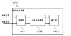
図29は、実施の形態11に係る映像表示装置3200の構成を示す図である。この映像表示装置3200は、映像信号および音声信号を処理して出力する装置であり、例えばテレビジョン放送の映像信号および音声信号を受信して、映像表示および音声出力を行うテレビジョン装置である。図29において、映像表示装置3200は、受信部3201、映像処理装置3202、および再生部3203を有する。なお、再生部3203は、映像表示装置3200の外部に構成されてもよい。
Embodiment 11 FIG.
FIG. 29 is a diagram showing the configuration of the video display apparatus 3200 according to the eleventh embodiment. The video display device 3200 is a device that processes and outputs a video signal and an audio signal. For example, the video display device 3200 is a television device that receives a video signal and an audio signal of a television broadcast and performs video display and audio output. In FIG. 29, the video display device 3200 includes a receiving unit 3201, a video processing device 3202, and a playback unit 3203. Note that the playback unit 3203 may be configured outside the video display device 3200.

受信部3201は、デジタルテレビジョン放送の映像信号および音声信号など、放送された映像信号および音声信号を受信する。   The receiving unit 3201 receives broadcast video signals and audio signals such as digital television broadcast video signals and audio signals.

映像処理装置3202は、上記実施の形態1〜10のいずれかに係る映像処理装置であり、受信部3201により受信された映像信号および音声信号を受け、当該映像信号に対してテロップ置換処理を行い、出力映像信号と出力音声信号とを出力する。映像処理装置3202は、実施の形態1〜4のようにテロップ置換処理を行ってもよいし、実施の形態5〜10のように緊急警報放送信号、データ放送信号に含まれる情報、または音声信号に含まれる速報音に基づいて選択的にテロップ置換処理を行ってもよい。   The video processing device 3202 is the video processing device according to any of Embodiments 1 to 10, receives the video signal and the audio signal received by the receiving unit 3201, and performs telop replacement processing on the video signal. The output video signal and the output audio signal are output. The video processing device 3202 may perform the telop replacement process as in the first to fourth embodiments, or the information included in the emergency alert broadcast signal, the data broadcast signal, or the audio signal as in the fifth to tenth embodiments. The telop replacement process may be selectively performed based on the breaking sound included in the.

再生部3203は、映像処理装置3202から出力される出力映像信号および出力音声信号を再生する。例えば、再生部3203は、出力映像信号および出力音声信号に基づき、映像表示および音声出力を行う。   The playback unit 3203 plays back the output video signal and output audio signal output from the video processing device 3202. For example, the playback unit 3203 performs video display and audio output based on the output video signal and the output audio signal.

なお、実施の形態7で述べたように、映像処理装置3202には音声信号処理部2402が設けられており、音声信号に対しては、速報音の音量を増減する処理や、映像とのタイミングを合わせるための遅延処理(リップシンク)が行われる場合もある。   Note that, as described in Embodiment 7, the video processing device 3202 is provided with the audio signal processing unit 2402, and for the audio signal, processing for increasing / decreasing the volume of the breaking news sound and timing of the video In some cases, a delay process (lip sync) is performed to match the two.

実施の形態12.
図30は、実施の形態12に係る映像記録装置3300の構成を示す図である。この映像記録装置3300は、映像信号と音声信号とを処理して記録する装置であり、例えばテレビジョン放送の映像信号および音声信号を受信して記録するビデオレコーダである。図30において、映像記録装置3300は、受信部3301、映像処理装置3302、および記録部3303を有する。なお、記録部3303は、映像記録装置3300の外部に構成されてもよい。
Embodiment 12 FIG.
FIG. 30 is a diagram showing a configuration of a video recording apparatus 3300 according to the twelfth embodiment. The video recording device 3300 is a device that processes and records a video signal and an audio signal. For example, the video recording device 3300 is a video recorder that receives and records a video signal and an audio signal of a television broadcast. In FIG. 30, the video recording device 3300 includes a receiving unit 3301, a video processing device 3302, and a recording unit 3303. The recording unit 3303 may be configured outside the video recording apparatus 3300.

受信部3301は、デジタルテレビジョン放送の映像信号および音声信号など、放送された映像信号および音声信号を受信する。   The receiving unit 3301 receives broadcast video signals and audio signals such as digital television broadcast video signals and audio signals.

映像処理装置3302は、上記実施の形態1〜10のいずれかに係る映像処理装置であり、受信部3301により受信された映像信号および音声信号を受け、当該映像信号に対してテロップ置換処理を行い、出力映像信号と出力音声信号とを出力する。映像処理装置3202は、実施の形態1〜4のようにテロップ置換処理を行ってもよいし、実施の形態5〜10のように緊急警報放送信号、データ放送信号に含まれる情報、または音声信号に含まれる速報音に基づいて選択的にテロップ置換処理を行ってもよい。   The video processing device 3302 is the video processing device according to any of Embodiments 1 to 10, receives the video signal and the audio signal received by the receiving unit 3301, and performs telop replacement processing on the video signal. The output video signal and the output audio signal are output. The video processing device 3202 may perform the telop replacement process as in the first to fourth embodiments, or the information included in the emergency alert broadcast signal, the data broadcast signal, or the audio signal as in the fifth to tenth embodiments. The telop replacement process may be selectively performed based on the breaking sound included in the.

記録部3303は、映像処理装置3302から出力される出力映像信号および出力音声信号を、ハードディスクや光ディスク等の記録媒体に記録する。   The recording unit 3303 records the output video signal and the output audio signal output from the video processing device 3302 on a recording medium such as a hard disk or an optical disk.

なお、実施の形態7で述べたように、映像処理装置3302には音声信号処理部2402が設けられており、音声信号に対しては、速報音の音量を増減する処理や、映像とのタイミングを合わせるための遅延処理(リップシンク)が行われる場合もある。   Note that, as described in Embodiment 7, the audio signal processing unit 2402 is provided in the video processing device 3302, and for the audio signal, processing for increasing or decreasing the volume of the breaking news sound and timing with the video are performed. In some cases, a delay process (lip sync) is performed to match the two.

また、映像記録装置3300は、映像処理装置3302から出力される出力映像信号または記録部3303により記録された映像信号を表示する表示部や、映像処理装置3302から出力される出力音声信号または記録部3303により記録された音声信号を出力する出力部をさらに備える映像記録表示装置であってもよい。   In addition, the video recording device 3300 includes a display unit that displays an output video signal output from the video processing device 3302 or a video signal recorded by the recording unit 3303, and an output audio signal or recording unit output from the video processing device 3302. The video recording / displaying device may further include an output unit that outputs the audio signal recorded in 3303.

実施の形態13.
図31は、実施の形態13に係る映像記録再生装置3400の構成を示す図である。この映像記録再生装置3400は、映像信号と音声信号とを処理して記録し、再生する装置であり、例えばテレビジョン放送の映像信号および音声信号を受信して記録、再生するビデオレコーダである。図31において、映像記録再生装置3400は、受信部3401、記録部3402、映像処理装置3403、および再生部3404を有する。なお、再生部3404は、映像記録再生装置3400の外部に構成されてもよい。
Embodiment 13 FIG.
FIG. 31 is a diagram showing a configuration of a video recording / reproducing apparatus 3400 according to the thirteenth embodiment. The video recording / reproducing apparatus 3400 is an apparatus that processes, records, and reproduces a video signal and an audio signal. For example, the video recording / reproducing apparatus 3400 is a video recorder that receives, records, and reproduces a video signal and an audio signal of a television broadcast. In FIG. 31, the video recording / playback apparatus 3400 includes a receiving unit 3401, a recording unit 3402, a video processing device 3403, and a playback unit 3404. Note that the playback unit 3404 may be configured outside the video recording / playback apparatus 3400.

受信部3401は、デジタルテレビジョン放送の映像信号および音声信号など、放送された映像信号および音声信号を受信する。   The receiving unit 3401 receives broadcast video signals and audio signals such as digital television broadcast video signals and audio signals.

記録部3402は、受信部3401から出力される出力映像信号および出力音声信号を、ハードディスクや光ディスク等の記録媒体に記録する。   The recording unit 3402 records the output video signal and the output audio signal output from the receiving unit 3401 on a recording medium such as a hard disk or an optical disk.

映像処理装置3403は、上記実施の形態1〜10のいずれかに係る映像処理装置であり、記録部3402により記録され、記録媒体から読み出された映像信号および音声信号を受け、当該映像信号に対してテロップ置換処理を行い、出力映像信号と出力音声信号とを出力する。映像処理装置3202は、実施の形態1〜4のようにテロップ置換処理を行ってもよいし、実施の形態5〜10のように緊急警報放送信号、データ放送信号に含まれる情報、または音声信号に含まれる速報音に基づいて選択的にテロップ置換処理を行ってもよい。   The video processing device 3403 is a video processing device according to any of Embodiments 1 to 10, receives a video signal and an audio signal recorded by the recording unit 3402 and read from the recording medium, and receives the video signal. On the other hand, the telop replacement process is performed to output an output video signal and an output audio signal. The video processing device 3202 may perform the telop replacement process as in the first to fourth embodiments, or the information included in the emergency alert broadcast signal, the data broadcast signal, or the audio signal as in the fifth to tenth embodiments. The telop replacement process may be selectively performed based on the breaking sound included in the.

再生部3404は、映像処理装置3403から出力される出力映像信号および出力音声信号を再生する。例えば、再生部3404は、出力映像信号および出力音声信号に基づき、映像表示および音声出力を行う。   The playback unit 3404 plays back the output video signal and output audio signal output from the video processing device 3403. For example, the playback unit 3404 performs video display and audio output based on the output video signal and the output audio signal.

なお、実施の形態7で述べたように、映像処理装置3403には音声信号処理部2402が設けられており、音声信号に対しては、速報音の音量を増減する処理や、映像とのタイミングを合わせるための遅延処理(リップシンク)が行われる場合もある。   Note that as described in Embodiment 7, the audio processing unit 2402 is provided in the video processing device 3403, and for the audio signal, processing for increasing / decreasing the volume of the breaking news and timing of the video In some cases, a delay process (lip sync) is performed to match the two.

以上説明した実施の形態1〜13において、映像処理装置の機能は、電子回路などのハードウェア資源のみにより実現されてもよいし、ハードウェア資源とソフトウェアとの協働により実現されてもよい。ハードウェア資源とソフトウェアとの協働により実現される場合、映像処理装置の機能は、例えば映像処理プログラムがコンピュータにより実行されることによって実現される。より具体的には、映像処理装置の機能は、ROM(Read Only Memory)等の記録媒体に記録された映像処理プログラムが主記憶装置に読み出されて中央処理装置(CPU:Central Processing Unit)により実行されることによって実現される。映像処理プログラムは、光ディスク等のコンピュータ読み取り可能な記録媒体に記録されて提供されてもよいし、インターネット等の通信回線を介して提供されてもよい。   In Embodiments 1 to 13 described above, the functions of the video processing apparatus may be realized only by hardware resources such as an electronic circuit, or may be realized by cooperation of hardware resources and software. When realized by the cooperation of hardware resources and software, the function of the video processing apparatus is realized by, for example, a video processing program being executed by a computer. More specifically, the function of the video processing device is as follows. A video processing program recorded on a recording medium such as a ROM (Read Only Memory) is read out to the main storage device, and is executed by a central processing unit (CPU). It is realized by being executed. The video processing program may be provided by being recorded on a computer-readable recording medium such as an optical disk, or may be provided via a communication line such as the Internet.

なお、本発明は、上記実施の形態に限定されるものではなく、本発明の要旨を逸脱しない範囲内において種々の態様で実施することができる。   In addition, this invention is not limited to the said embodiment, In the range which does not deviate from the summary of this invention, it can implement with a various aspect.

例えば、実施の形態1〜13において、テロップ検出部102とテロップチェンジ検出部103とを1つにして、テロップ/テロップチェンジ検出部を設けてもよい。図32には、テロップ検出部102およびテロップチェンジ検出部103の代わりに、テロップ/テロップチェンジ検出部3501を備える映像処理装置3500の構成が例示されている。テロップ/テロップチェンジ検出部3501は、テロップ検出部102の機能とテロップチェンジ検出部103の機能とを合わせた機能を有する。   For example, in Embodiments 1 to 13, the telop detection unit 102 and the telop change detection unit 103 may be combined into a single telop / telop change detection unit. FIG. 32 illustrates a configuration of a video processing apparatus 3500 including a telop / telop change detection unit 3501 instead of the telop detection unit 102 and the telop change detection unit 103. The telop / telop change detection unit 3501 has a function that combines the function of the telop detection unit 102 and the function of the telop change detection unit 103.

また、上記実施の形態1〜13のそれぞれの構成は、上記以外の態様で適宜組み合わされてもよい。例えば、実施の形態7〜10の構成は、実施の形態2〜6に係る映像処理装置に適用されてもよい。すなわち、実施の形態2〜6に係る映像処理装置は、実施の形態7〜10のように、速報音を検出し、この検出結果に基づいて、速報音を伴うテロップのテロップ領域を選択的に置き換えるように構成されてもよい。また、実施の形態2〜6に係る映像処理装置は、実施の形態7〜10のように、速報音の検出結果に基づいて、入力音声信号に対して速報音の音量を低減する処理を行うように構成されてもよい。実施の形態4に対して実施の形態10の特徴が追加された構成では、文字認識部1801は、テロップ有りと判定した場合、判定結果をテロップ検出部102に送る代わりに、システム制御部3101に対し、テロップの検出時刻が速報音の検出から所定時間以内であるかを問い合わせ、所定時間以内である場合にのみ、あらためてテロップ有りと判定して、判定結果をテロップ検出部102に送ってもよい。   Moreover, each structure of the said Embodiment 1-13 may be combined suitably with aspects other than the above. For example, the configurations of the seventh to tenth embodiments may be applied to the video processing devices according to the second to sixth embodiments. That is, the video processing apparatus according to the second to sixth embodiments detects the breaking sound as in the seventh to tenth embodiments, and selectively selects the telop area of the telop with the breaking sound based on the detection result. It may be configured to replace. In addition, the video processing devices according to the second to sixth embodiments perform processing for reducing the volume of the breaking sound on the input sound signal based on the detection result of the breaking sound as in the seventh to tenth embodiments. It may be configured as follows. In the configuration in which the features of the tenth embodiment are added to the fourth embodiment, when the character recognition unit 1801 determines that there is a telop, the character recognition unit 1801 sends the determination result to the system control unit 3101 instead of sending the determination result to the telop detection unit 102. On the other hand, it is inquired whether the detection time of the telop is within a predetermined time from the detection of the breaking sound, and only when it is within the predetermined time, it is determined that the telop is present, and the determination result may be sent to the telop detection unit 102. .

また、上記実施の形態1〜13の映像処理部105は、テロップが出現する前の映像フレームから得られる画像に置き換える置換方法の代わりに、置換対象の映像フレームのテロップ領域の周辺画素から得られる画像に置き換える置換方法を使用してもよい。例えば、映像処理部105は、図5および図8のテロップT1の補間に、テロップ領域の周辺画素から得られる画像に置き換える置換方法を使用してもよい。   In addition, the video processing unit 105 according to the first to thirteenth embodiments is obtained from the peripheral pixels of the telop area of the video frame to be replaced, instead of the replacement method of replacing the image obtained from the video frame before the telop appears. A replacement method for replacing with an image may be used. For example, the video processing unit 105 may use a replacement method in which the image obtained from the peripheral pixels in the telop area is used for the interpolation of the telop T1 in FIGS.

また、上記の説明では、順次入力される一連の映像フレームを順次処理する構成を主に例示したが、映像処理装置は、一連の映像フレームを必ずしも順次またはフレームの順番通りに処理する必要はない。例えば、映像処理装置は、記録媒体に記録された映像信号を処理してもよく、この場合、様々な処理手順で処理することができる。また、実施の形態7〜10では、順次入力される映像信号および音声信号を順次処理する構成を主に例示したが、実施の形態7〜10に係る映像処理装置は、映像信号および音声信号を必ずしも順次またはフレームの順番通りに処理する必要はない。例えば、映像処理装置は、記録媒体に記録された映像信号および音声信号を処理してもよく、この場合、様々な処理手順で処理することができる。   In the above description, the configuration mainly for sequentially processing a series of video frames that are sequentially input is illustrated, but the video processing apparatus does not necessarily have to process a series of video frames sequentially or in the order of the frames. . For example, the video processing apparatus may process a video signal recorded on a recording medium, and in this case, the video processing apparatus can process the video signal according to various processing procedures. Further, in Embodiments 7 to 10, the configuration in which video signals and audio signals that are sequentially input are sequentially processed is mainly exemplified. However, the video processing apparatus according to Embodiments 7 to 10 receives video signals and audio signals. It is not always necessary to perform processing sequentially or in the order of frames. For example, the video processing apparatus may process a video signal and an audio signal recorded on a recording medium, and in this case, can be processed by various processing procedures.

また、実施の形態7〜10では、速報音が検出された時点近傍の所定期間、第1の所定期間、および第2の所定期間として、速報音が検出されてから所定時間以内の期間(すなわち速報音検出以降の期間)を例示したが、これらの所定期間は、速報音が検出される前の期間を含んでもよく、例えば、速報音の検出時刻の前後所定時間以内の期間であってもよい。また、実施の形態7〜10における各所定期間は、予め固定的に定められた期間でもよいし、予め定められた規則に基づいて映像処理装置によって可変的に決められてもよい。   In the seventh to tenth embodiments, the predetermined period, the first predetermined period, and the second predetermined period in the vicinity of the time point when the breaking sound is detected are periods within the predetermined time after the breaking sound is detected (that is, The period after the detection of the breaking sound is exemplified, but these predetermined periods may include a period before the breaking of the breaking sound, for example, a period within a predetermined time before and after the detection time of the breaking sound. Good. In addition, each predetermined period in Embodiments 7 to 10 may be a period fixed in advance, or may be variably determined by the video processing device based on a predetermined rule.

100,900,1600,1800,1900,2000,2400,3100,3202,3302,3403 映像処理装置、 101 映像記録部、 102 テロップ検出部、 103 テロップチェンジ検出部、 104 記録制御部、 105 映像処理部、 1601 シーンチェンジ検出部、 1801 文字認識部、 2001 データ放送解析部、 3200 映像表示装置、 3201,3301,3401 受信部、 3300 映像記録装置、 3303,3402 記録部、 3400 映像記録再生装置、 2401 速報音検出部、 2402 音声信号処理部、 3101 システム制御部、 3203,3404 再生部、 3501 テロップ/テロップチェンジ検出部。   100, 900, 1600, 1800, 1900, 2000, 2400, 3100, 3202, 3302, 3403 Video processing device, 101 video recording unit, 102 telop detection unit, 103 telop change detection unit, 104 recording control unit, 105 video processing unit 1601 Scene change detection unit, 1801 character recognition unit, 2001 data broadcast analysis unit, 3200 video display device, 3201, 3301, 3401 reception unit, 3300 video recording device, 3303, 3402 recording unit, 3400 video recording / playback device, 2401 Sound detection unit, 2402 audio signal processing unit, 3101 system control unit, 3203, 3404 playback unit, 3501 telop / telop change detection unit.

Claims (17)

入力される一連の映像フレームからテロップを含むテロップ領域を検出するテロップ検出部と、
前記一連の映像フレームに対応し、入力される一連の音声信号から速報音を検出する速報音検出部と、
前記一連の映像フレームのうち前記テロップ領域が検出された映像フレームにおける前記テロップ領域を、前記一連の映像フレームのうち前記テロップ領域のテロップが出現する前の映像フレームから得られる画像に置き換え、前記テロップ領域が置き換えられた映像フレームを出力する映像処理部と、
を備え、
前記映像処理部は、前記速報音検出部の検出結果に基づき、前記速報音を伴うテロップのテロップ領域を選択的に置き換える、
ことを特徴とする映像処理装置。
A telop detection unit for detecting a telop area including a telop from a series of input video frames;
Corresponding to the series of video frames, a breaking sound detection unit for detecting breaking sound from a series of input audio signals;
Replacing the telop area in the video frame in which the telop area is detected in the series of video frames with an image obtained from a video frame before the telop in the telop area appears in the series of video frames; A video processing unit for outputting a video frame in which the area is replaced;
With
The video processing unit selectively replaces the telop area of the telop with the breaking sound based on the detection result of the breaking sound detection unit,
A video processing apparatus characterized by that.
前記一連の映像フレームからテロップの出現を検出するテロップチェンジ検出部と、
前記テロップチェンジ検出部の検出結果に基づき、前記一連の映像フレームのうち前記テロップが出現する前の映像フレームを記録する置換用映像記録部と、
をさらに備え、
前記映像処理部は、前記記録された映像フレームから得られる画像に前記テロップ領域を置き換える、
ことを特徴とする請求項1に記載の映像処理装置。
A telop change detector for detecting the appearance of a telop from the series of video frames;
Based on the detection result of the telop change detection unit, a replacement video recording unit that records a video frame before the telop appears in the series of video frames;
Further comprising
The video processing unit replaces the telop area with an image obtained from the recorded video frame;
The video processing apparatus according to claim 1.
前記一連の映像フレームが順次入力され、現映像フレームとその前の映像フレームとを記録する映像記録部をさらに備え、
前記テロップ検出部は、前記記録された現映像フレームについて前記テロップ領域の検出を行い、
前記テロップチェンジ検出部は、前記記録された現映像フレームについて前記テロップの出現の検出を行い、
前記置換用映像記録部は、前記テロップチェンジ検出部により前記テロップの出現が検出された場合に、前記記録された現映像フレームの前の映像フレームを、前記テロップが出現する前の映像フレームとして記録し、
前記映像処理部は、前記テロップ検出部により前記テロップ領域が検出された場合に、前記現映像フレームにおける前記テロップ領域を、前記記録された前記テロップが出現する前の映像フレームから得られる画像に置き換え、前記テロップ領域が置き換えられた現映像フレームを出力する、
ことを特徴とする請求項2に記載の映像処理装置。
The series of video frames are sequentially input, and further includes a video recording unit that records the current video frame and the previous video frame,
The telop detection unit detects the telop area for the recorded current video frame,
The telop change detection unit detects the appearance of the telop for the recorded current video frame,
The replacement video recording unit records a video frame before the recorded current video frame as a video frame before the telop appears when the telop change detection unit detects the appearance of the telop. And
When the telop detection unit detects the telop area, the video processing unit replaces the telop area in the current video frame with an image obtained from the video frame before the recorded telop appears. Outputting a current video frame in which the telop area is replaced;
The video processing apparatus according to claim 2.
前記テロップチェンジ検出部は、前記一連の映像フレームからテロップの出現および切り替わりをテロップチェンジとして検出し、
前記映像処理部は、前記テロップ領域が検出された映像フレームにおける前記テロップ領域を置き換える場合、前記テロップチェンジ検出部の検出結果に基づき、前記置換対象の映像フレームの直前のテロップチェンジがテロップの出現であるときには、前記テロップ領域のテロップが出現する前の映像フレームから得られる画像に置き換え、前記置換対象の映像フレームの直前のテロップチェンジがテロップの切り替わりであるときには、前記置換対象の映像フレームの前記テロップ領域の周辺画素から得られる画像に置き換える、
ことを特徴とする請求項2または3に記載の映像処理装置。
The telop change detection unit detects the appearance and switching of a telop as a telop change from the series of video frames,
When the video processing unit replaces the telop area in the video frame in which the telop area is detected, the telop change immediately before the replacement target video frame is based on the detection result of the telop change detection unit. When there is a telop in the telop area, the telop is replaced with an image obtained from a video frame before the telop appears, and when the telop change immediately before the replacement target video frame is a telop change, the telop of the replacement target video frame is displayed. Replace with the image obtained from the surrounding pixels of the area,
The video processing apparatus according to claim 2 or 3, wherein
前記テロップチェンジ検出部は、テロップを構成する文字のエッジおよび当該文字の輪郭部のエッジを検出し、検出されるエッジの変化に基づいて前記テロップの出現または切り替わりを検出することを特徴とする請求項2から4のいずれか1項に記載の映像処理装置。   The telop change detection unit detects an edge of a character constituting a telop and an edge of a contour portion of the character, and detects appearance or switching of the telop based on a change in the detected edge. Item 5. The video processing device according to any one of Items 2 to 4. 前記一連の映像フレームからシーンチェンジを検出するシーンチェンジ検出部をさらに備え、
前記映像処理部は、前記テロップ領域が検出された映像フレームにおける前記テロップ領域を置き換える場合、前記シーンチェンジ検出部の検出結果に基づき、前記テロップ領域のテロップが出現する前の映像フレームと前記置換対象の映像フレームとの間でシーンチェンジが発生していないときには、前記テロップ領域のテロップが出現する前の映像フレームから得られる画像に置き換え、前記映像フレーム間でシーンチェンジが発生しているときには、前記置換対象の映像フレームの前記テロップ領域の周辺画素から得られる画像に置き換える、
ことを特徴とする請求項1から5のいずれか1項に記載の映像処理装置。
A scene change detector for detecting a scene change from the series of video frames;
When the video processing unit replaces the telop area in the video frame in which the telop area is detected, based on the detection result of the scene change detection unit, the video frame before the telop in the telop area appears and the replacement target When no scene change has occurred between the video frames, the image is replaced with an image obtained from a video frame before the appearance of the telop in the telop area, and when a scene change has occurred between the video frames, Replace with the image obtained from the peripheral pixels of the telop area of the video frame to be replaced,
The video processing apparatus according to claim 1, wherein the video processing apparatus is an image processing apparatus.
前記テロップ検出部は、前記映像フレームに対して文字認識を行い、当該文字認識の結果に基づき、文字情報を含む領域を前記テロップ領域として検出することを特徴とする請求項1から6のいずれか1項に記載の映像処理装置。   The telop detection unit performs character recognition on the video frame, and detects an area including character information as the telop area based on the result of the character recognition. The video processing apparatus according to item 1. 緊急警報放送信号を受けた場合には、前記テロップ領域の置き換えを行わないことを特徴とする請求項1から7のいずれか1項に記載の映像処理装置。   The video processing apparatus according to claim 1, wherein the telop area is not replaced when an emergency warning broadcast signal is received. データ放送信号を受け、当該データ放送信号に所定の情報が含まれる場合には、前記テロップ領域の置き換えを行わないことを特徴とする請求項1から8のいずれか1項に記載の映像処理装置。   9. The video processing apparatus according to claim 1, wherein a data broadcast signal is received and the telop area is not replaced when the data broadcast signal includes predetermined information. . 前記映像処理部は、前記速報音が検出された時点近傍の所定期間内に検出されたテロップ領域を選択的に置き換えることを特徴とする請求項1から9のいずれか1項に記載の映像処理装置。   The video processing according to any one of claims 1 to 9, wherein the video processing unit selectively replaces a telop area detected within a predetermined period in the vicinity of the time point when the breaking sound is detected. apparatus. 前記一連の映像フレームからテロップの出現を検出するテロップチェンジ検出部を備え、
前記映像処理部は、前記速報音が検出された時点近傍の第1の所定期間内に前記テロップの出現が検出された場合に、当該速報音が検出された時点近傍の第2の所定期間内に検出されたテロップ領域を選択的に置き換える、
ことを特徴とする請求項1から9のいずれか1項に記載の映像処理装置。
A telop change detection unit that detects the appearance of a telop from the series of video frames,
When the appearance of the telop is detected within a first predetermined period in the vicinity of the time point when the breaking sound is detected, the video processing unit is within a second predetermined period in the vicinity of the time point when the breaking sound is detected. Selectively replace the detected telop area in
The video processing apparatus according to claim 1, wherein the video processing apparatus is a video processing apparatus.
前記一連の映像フレームからテロップの出現を検出するテロップチェンジ検出部を備え、
前記映像処理部は、前記速報音が検出された時点近傍の所定期間内に前記テロップの出現が検出された場合に、当該テロップを含むテロップ領域を選択的に置き換える、
ことを特徴とする請求項1から9のいずれか1項に記載の映像処理装置。
A telop change detection unit that detects the appearance of a telop from the series of video frames,
The video processing unit selectively replaces a telop area including the telop when the appearance of the telop is detected within a predetermined period in the vicinity of the time point when the breaking sound is detected.
The video processing apparatus according to claim 1, wherein the video processing apparatus is a video processing apparatus.
前記音声信号に対して、前記速報音検出部により検出された速報音の音量を低減する処理を行う音声信号処理部をさらに備えることを特徴とする請求項1から12のいずれか1項に記載の映像処理装置。   13. The audio signal processing unit according to claim 1, further comprising: an audio signal processing unit that performs a process of reducing a volume of the breaking sound detected by the breaking sound detection unit with respect to the sound signal. Video processing equipment. 請求項1から13のいずれか1項に記載の映像処理装置と、
前記映像処理装置の前記映像処理部から出力される映像フレームを表示する再生部と、
を備えることを特徴とする映像表示装置。
The video processing device according to any one of claims 1 to 13,
A playback unit for displaying a video frame output from the video processing unit of the video processing device;
A video display device comprising:
請求項1から13のいずれか1項に記載の映像処理装置と、
前記映像処理装置の前記映像処理部から出力される映像フレームを記録する記録部と、
を備えることを特徴とする映像記録装置。
The video processing device according to any one of claims 1 to 13,
A recording unit for recording a video frame output from the video processing unit of the video processing device;
A video recording apparatus comprising:
入力される一連の映像フレームからテロップを含むテロップ領域を検出するテロップ検出ステップと、
前記一連の映像フレームに対応し、入力される一連の音声信号から速報音を検出する速報音検出ステップと、
前記一連の映像フレームのうち前記テロップ領域が検出された映像フレームにおける前記テロップ領域を、前記一連の映像フレームのうち前記テロップ領域のテロップが出現する前の映像フレームから得られる画像に置き換え、前記テロップ領域が置き換えられた映像フレームを出力する映像処理ステップと、
を有し、
前記映像処理ステップは、前記速報音検出部の検出結果に基づき、前記速報音を伴うテロップのテロップ領域を選択的に置き換える、
ことを特徴とする映像処理方法。
A telop detection step for detecting a telop area including a telop from a series of input video frames;
Corresponding to the series of video frames, a breaking sound detection step for detecting breaking sound from a series of input audio signals;
Replacing the telop area in the video frame in which the telop area is detected in the series of video frames with an image obtained from a video frame before the telop in the telop area appears in the series of video frames; A video processing step for outputting a video frame in which the area is replaced;
Have
The video processing step selectively replaces the telop area of the telop with the breaking sound based on the detection result of the breaking sound detection unit.
And a video processing method.
入力される一連の映像フレームからテロップを含むテロップ領域を検出するテロップ検出ステップと、
前記一連の映像フレームに対応し、入力される一連の音声信号から速報音を検出する速報音検出ステップと、
前記一連の映像フレームのうち前記テロップ領域が検出された映像フレームにおける前記テロップ領域を、前記一連の映像フレームのうち前記テロップ領域のテロップが出現する前の映像フレームから得られる画像に置き換え、前記テロップ領域が置き換えられた映像フレームを出力する映像処理ステップと、
をコンピュータに実行させ、
前記映像処理ステップは、前記速報音検出部の検出結果に基づき、前記速報音を伴うテロップのテロップ領域を選択的に置き換える、
ことを特徴とする映像処理プログラム。
A telop detection step for detecting a telop area including a telop from a series of input video frames;
Corresponding to the series of video frames, a breaking sound detection step for detecting breaking sound from a series of input audio signals;
Replacing the telop area in the video frame in which the telop area is detected in the series of video frames with an image obtained from a video frame before the telop in the telop area appears in the series of video frames; A video processing step for outputting a video frame in which the area is replaced;
To the computer,
The video processing step selectively replaces the telop area of the telop with the breaking sound based on the detection result of the breaking sound detection unit.
A video processing program characterized by that.
JP2012216082A 2011-10-19 2012-09-28 Video processing device, video display device, video recording device, video processing method, and video processing program Pending JP2013179563A (en)

Priority Applications (1)

Application Number Priority Date Filing Date Title
JP2012216082A JP2013179563A (en) 2011-10-19 2012-09-28 Video processing device, video display device, video recording device, video processing method, and video processing program

Applications Claiming Priority (5)

Application Number Priority Date Filing Date Title
JP2011229640 2011-10-19
JP2012026852 2012-02-10
JP2012216082A JP2013179563A (en) 2011-10-19 2012-09-28 Video processing device, video display device, video recording device, video processing method, and video processing program

Publications (2)

Publication Number Publication Date
JP2013179563A true JP2013179563A (en) 2013-09-09
JP2013179563A5 JP2013179563A5 (en) 2015-07-23

Family

ID=48135675

Family Applications (1)

Application Number Title Priority Date Filing Date
JP2012216082A Pending JP2013179563A (en) 2011-10-19 2012-09-28 Video processing device, video display device, video recording device, video processing method, and video processing program

Country Status (3)

Country Link
US (1) US20130100346A1 (en)
JP (1) JP2013179563A (en)
CN (1) CN103106911A (en)

Cited By (1)

* Cited by examiner, † Cited by third party
Publication number Priority date Publication date Assignee Title
CN105163188A (en) * 2015-08-31 2015-12-16 小米科技有限责任公司 Video content processing method, device and apparatus

Families Citing this family (3)

* Cited by examiner, † Cited by third party
Publication number Priority date Publication date Assignee Title
JP5349649B1 (en) * 2012-05-25 2013-11-20 株式会社東芝 Electronic device, electronic device control method, electronic device control program
CN111193965B (en) * 2020-01-15 2022-09-06 北京奇艺世纪科技有限公司 Video playing method, video processing method and device
CN111626922B (en) * 2020-05-11 2023-09-15 北京字节跳动网络技术有限公司 Picture generation method and device, electronic equipment and computer readable storage medium

Citations (6)

* Cited by examiner, † Cited by third party
Publication number Priority date Publication date Assignee Title
JPH09200684A (en) * 1996-01-12 1997-07-31 Sony Corp Video/audio signal recording device
JP2004072617A (en) * 2002-08-08 2004-03-04 Sony Corp Device and method system for detecting particular information, program, recording medium, and system for detecting particular information
JP2005252372A (en) * 2004-03-01 2005-09-15 Ntt Docomo Tokai Inc Digest video image producing device and method
JP2008118232A (en) * 2006-11-01 2008-05-22 Hitachi Ltd Video image reproducing unit
JP2009003598A (en) * 2007-06-20 2009-01-08 Sony Corp Image generation device and method, learning device and method, and program
JP2009147749A (en) * 2007-12-14 2009-07-02 Toshiba Corp Video playback apparatus and video playback method

Family Cites Families (7)

* Cited by examiner, † Cited by third party
Publication number Priority date Publication date Assignee Title
US6553100B1 (en) * 2000-11-07 2003-04-22 At&T Corp. Intelligent alerting systems
US7089575B2 (en) * 2001-09-04 2006-08-08 Koninklijke Philips Electronics N.V. Method of using transcript information to identify and learn commercial portions of a program
JP4613867B2 (en) * 2005-05-26 2011-01-19 ソニー株式会社 Content processing apparatus, content processing method, and computer program
JP2007316613A (en) * 2006-04-26 2007-12-06 Matsushita Electric Ind Co Ltd Caption display control apparatus
US20090150925A1 (en) * 2007-12-06 2009-06-11 At&T Labs, Inc. System and Method of Providing An Alert
US20100007791A1 (en) * 2008-07-09 2010-01-14 Mark Meister Television display editor
JP4929368B2 (en) * 2010-03-11 2012-05-09 株式会社東芝 Video transmission device and subtitle replacement method

Patent Citations (6)

* Cited by examiner, † Cited by third party
Publication number Priority date Publication date Assignee Title
JPH09200684A (en) * 1996-01-12 1997-07-31 Sony Corp Video/audio signal recording device
JP2004072617A (en) * 2002-08-08 2004-03-04 Sony Corp Device and method system for detecting particular information, program, recording medium, and system for detecting particular information
JP2005252372A (en) * 2004-03-01 2005-09-15 Ntt Docomo Tokai Inc Digest video image producing device and method
JP2008118232A (en) * 2006-11-01 2008-05-22 Hitachi Ltd Video image reproducing unit
JP2009003598A (en) * 2007-06-20 2009-01-08 Sony Corp Image generation device and method, learning device and method, and program
JP2009147749A (en) * 2007-12-14 2009-07-02 Toshiba Corp Video playback apparatus and video playback method

Cited By (1)

* Cited by examiner, † Cited by third party
Publication number Priority date Publication date Assignee Title
CN105163188A (en) * 2015-08-31 2015-12-16 小米科技有限责任公司 Video content processing method, device and apparatus

Also Published As

Publication number Publication date
US20130100346A1 (en) 2013-04-25
CN103106911A (en) 2013-05-15

Similar Documents

Publication Publication Date Title
KR101482025B1 (en) Augmented reality presentations
KR101987820B1 (en) Content processing device for processing high resolution content and method thereof
CN101197984B (en) Image processing apparatus, image processing method
US9001272B2 (en) Image synthesizing device, coding device, program, and recording medium
US7657847B2 (en) Copy control information deciding apparatus
US20080150964A1 (en) Method and apparatus for displaying content
JP2009076970A (en) Summary content generation device and computer program
CN105407381A (en) Video program play method and device
JP2013179563A (en) Video processing device, video display device, video recording device, video processing method, and video processing program
CN109691118B (en) Image display system and image display method
JP2010277647A (en) Printing device, printing method, and printing program
US20020150380A1 (en) Information reproducing apparatus and method of same
JP2006005418A (en) Apparatus, method, and program for receiving/reproducing information, and program recording medium
KR102220088B1 (en) Method and device for determining intercut time bucket in audio or video
JP2008304905A (en) Image quality adjustment device, method and program for image quality adjustment
JP6080667B2 (en) Video signal processing apparatus and method, program, and recording medium
JP2009147749A (en) Video playback apparatus and video playback method
CN101350897B (en) Moving image reproducing apparatus and control method of moving image reproducing apparatus
JP5242762B2 (en) Image reproducing apparatus, image reproducing method, and data structure
JP2008252746A (en) Digital broadcast receiver
JP4929127B2 (en) CM detecting method and moving picture reproducing apparatus using the same
JP6363015B2 (en) Electronic device and display method
WO2021039192A1 (en) Image processing apparatus, image processing method, and program
JP2006148631A (en) Reproduction processor
JP2014191047A (en) Media player and display device

Legal Events

Date Code Title Description
A521 Request for written amendment filed

Free format text: JAPANESE INTERMEDIATE CODE: A523

Effective date: 20150604

A621 Written request for application examination

Free format text: JAPANESE INTERMEDIATE CODE: A621

Effective date: 20150604

A977 Report on retrieval

Free format text: JAPANESE INTERMEDIATE CODE: A971007

Effective date: 20160311

A131 Notification of reasons for refusal

Free format text: JAPANESE INTERMEDIATE CODE: A131

Effective date: 20160315

A521 Request for written amendment filed

Free format text: JAPANESE INTERMEDIATE CODE: A523

Effective date: 20160428

A02 Decision of refusal

Free format text: JAPANESE INTERMEDIATE CODE: A02

Effective date: 20160809