JP2013169237A - Cleaning implement - Google Patents

Cleaning implement Download PDF

Info

Publication number
JP2013169237A
JP2013169237A JP2012033077A JP2012033077A JP2013169237A JP 2013169237 A JP2013169237 A JP 2013169237A JP 2012033077 A JP2012033077 A JP 2012033077A JP 2012033077 A JP2012033077 A JP 2012033077A JP 2013169237 A JP2013169237 A JP 2013169237A
Authority
JP
Japan
Prior art keywords
cleaning
cleaning head
scraping
shaped
head portion
Prior art date
Legal status (The legal status is an assumption and is not a legal conclusion. Google has not performed a legal analysis and makes no representation as to the accuracy of the status listed.)
Pending
Application number
JP2012033077A
Other languages
Japanese (ja)
Inventor
Kazunobu Nakamoto
和伸 中本
Hirobumi Moriwaka
博文 森若
Current Assignee (The listed assignees may be inaccurate. Google has not performed a legal analysis and makes no representation or warranty as to the accuracy of the list.)
Kao Corp
Original Assignee
Kao Corp
Priority date (The priority date is an assumption and is not a legal conclusion. Google has not performed a legal analysis and makes no representation as to the accuracy of the date listed.)
Filing date
Publication date
Application filed by Kao Corp filed Critical Kao Corp
Priority to JP2012033077A priority Critical patent/JP2013169237A/en
Publication of JP2013169237A publication Critical patent/JP2013169237A/en
Pending legal-status Critical Current

Links

Images

Abstract

PROBLEM TO BE SOLVED: To provide a cleaning implement capable of effectively wiping dust or soil on a surface to be cleaned, and capable of cleaning the surface to be cleaned by effectively adhering wiped dust or soil in a wide region on a cleaning sheet which is attached by covering a cleaning surface of a cleaning head.SOLUTION: A cleaning implement 10 includes a cleaning head 11 and a handle portion 12. A cleaning sheet 13 is attached by covering a cleaning surface 11a on a lower surface of the cleaning head 11 and a surface to be cleaned is wiped by the cleaning sheet 13. A plurality of scratching projections 14 are protruded on the cleaning surface 11a. These plurality of scratching projections 14 have a shape including V-shaped parts or substantially V-shaped parts 14a in a plan view, and are arranged so that open sides of the V-shaped parts or the substantially V-shaped parts 14a face toward a main cleaning direction X. The scratching projections 14 formed on an outermost periphery, are arranged so that the open sides face outward from the cleaning head 11.

Description

本発明は、清掃面を覆って清掃シートが装着された清掃ヘッド部により被清掃面を払拭する清掃具に関する。   The present invention relates to a cleaning tool that covers a cleaning surface and wipes the surface to be cleaned by a cleaning head portion on which a cleaning sheet is mounted.

清掃面を覆って不織布等からなる清掃シートが装着された清掃ヘッド部によって被清掃面を払拭する清掃具は、清掃ヘッド部に取り付けられたハンドル部を手で持って被清掃面を払拭することにより清掃シートに塵埃や汚れを付着させて、手軽に清掃を行うことができる。   A cleaning tool that covers the cleaning surface and wipes the surface to be cleaned with the cleaning head portion to which a cleaning sheet made of non-woven fabric or the like is attached, wipes the surface to be cleaned by holding the handle portion attached to the cleaning head portion by hand. Thus, dust and dirt can be attached to the cleaning sheet, and cleaning can be easily performed.

かかる清掃具によれば、清掃面となる清掃ヘッド部の下面が単に平坦な面であると、被清掃面の塵埃や汚れを効率良く掻き取ることは難しいと考えられることから、清掃ヘッド部の下面に凸部や凹凸部を設けることで、掻き取り効果を向上させることが可能な清掃具が開示されている(例えば、特許文献1、特許文献2参照)。   According to such a cleaning tool, it is considered difficult to efficiently scrape off dust and dirt on the surface to be cleaned if the lower surface of the cleaning head portion to be the cleaning surface is simply a flat surface. There has been disclosed a cleaning tool capable of improving the scraping effect by providing a convex portion or an uneven portion on the lower surface (see, for example, Patent Document 1 and Patent Document 2).

特許第3027345号公報Japanese Patent No. 3027345 特開2007−54337号公報JP 2007-54337 A

特許文献1の清掃具や特許文献2の清掃用具は、清掃ヘッド部の下面の弾性クッション材による清掃面を湾曲した形状として、塵埃や汚れを清掃面の周縁部分から内側に取り込みやすくしたり、清掃面に複数の凸部や凹凸部を設けて、被清掃面の汚れを掻き取りやすくすることができるが、清掃面を覆って装着された清掃シートの更に広範な領域に、掻き取った塵埃や汚れを効率良く付着させながら、被清掃面の清掃を行うことを可能にする技術の開発が望まれている。   The cleaning tool of Patent Document 1 and the cleaning tool of Patent Document 2 have a curved shape of the cleaning surface by the elastic cushion material on the lower surface of the cleaning head part, making it easier to take dust and dirt inward from the peripheral portion of the cleaning surface, The surface to be cleaned can be easily scraped off by providing a plurality of protrusions and irregularities on the cleaning surface, but dust has been scraped off over a wider area of the cleaning sheet that covers the cleaning surface. Development of a technique that enables cleaning of a surface to be cleaned while efficiently attaching dirt and dirt is desired.

特に、清掃ヘッド部は、一般に矩形平面視形状を備えており、通常はこの矩形平面視形状の長辺と垂直な方向を主清掃方向として、被清掃面の清掃が行われる。このような最も多く行われる清掃の方向である主清掃方向に清掃を行った際に、清掃面を覆って装着された清掃シートの更に広範な領域に、掻き取った塵埃や汚れを効率良く付着させながら、被清掃面の清掃を行うことを可能にする技術の開発が望まれている。   In particular, the cleaning head generally has a rectangular plan view shape, and the surface to be cleaned is usually cleaned with the direction perpendicular to the long side of the rectangular plan view shape as the main cleaning direction. When cleaning is performed in the main cleaning direction, which is the most frequently performed cleaning direction, the scraped dust and dirt are efficiently attached to a wider area of the cleaning sheet that covers the cleaning surface. Therefore, it is desired to develop a technique that makes it possible to clean the surface to be cleaned.

本発明は、被清掃面の塵埃や汚れを効果的に掻き取ることができると共に、清掃ヘッド部の清掃面を覆って装着された清掃シートの更に広範囲な領域に、掻き取った塵埃や汚れを効率良く付着させながら被清掃面の清掃を行うことのできる清掃具を提供することを目的とする。   The present invention can effectively scrape off dust and dirt on the surface to be cleaned, and remove the dust and dirt on the cleaning sheet that covers the cleaning surface of the cleaning head portion over a wider area. It aims at providing the cleaning tool which can clean a to-be-cleaned surface, making it adhere efficiently.

本発明は、清掃ヘッド部と、ハンドル部とを備え、前記清掃ヘッド部の下面による清掃面を覆って清掃シートが装着されて、該清掃シートにより被清掃面を払拭する清掃具であって、前記清掃面には、複数の掻取り突起が突設されており、該複数の掻取り突起は、平面視してV字状部分又は略V字状部分を有しており、該複数の掻取り突起の少なくとも一部は、前記V字状部分又は略V字状部分の開放側を主清掃方向に向けて配設されている清掃具を提供することにより、上記目的を達成したものである。   The present invention is a cleaning tool that includes a cleaning head portion and a handle portion, covers a cleaning surface by a lower surface of the cleaning head portion, is attached with a cleaning sheet, and wipes the surface to be cleaned with the cleaning sheet, The cleaning surface is provided with a plurality of scraping projections, and the plurality of scraping projections have a V-shaped portion or a substantially V-shaped portion in plan view, and the plurality of scraping projections. At least a part of the take-up protrusion achieves the above-mentioned object by providing a cleaning tool in which the open side of the V-shaped portion or the substantially V-shaped portion is disposed in the main cleaning direction. .

本発明の清掃具によれば、被清掃面の塵埃や汚れを効果的に掻き取ることができると共に、清掃ヘッド部の清掃面を覆って装着された清掃シートの更に広範囲な領域に、掻き取った塵埃や汚れを効率良く付着させながら被清掃面の清掃を行うことができる。   According to the cleaning tool of the present invention, it is possible to effectively scrape dust and dirt on the surface to be cleaned, and to scrape the cleaning sheet over a wider area of the cleaning sheet mounted so as to cover the cleaning surface of the cleaning head unit. The surface to be cleaned can be cleaned while efficiently attaching dust and dirt.

本発明の好ましい一実施形態に係る清掃具の全体構成を説明する斜視図である。It is a perspective view explaining the whole cleaning tool composition concerning one desirable embodiment of the present invention. 清掃ヘッド部の構成を説明する分解斜視図である。It is a disassembled perspective view explaining the structure of a cleaning head part. (a)は本発明の好ましい一実施形態に係る清掃具の要部を説明する清掃ヘッド部の底面図、(b)は掻取り突起の拡大平面図である。(A) is a bottom view of the cleaning head part explaining the principal part of the cleaning tool which concerns on preferable one Embodiment of this invention, (b) is an enlarged plan view of a scraping protrusion. (a)、(b)は、清掃具の清掃ヘッド部の他の形態を例示する清掃ヘッド部の底面図である。(A), (b) is a bottom view of the cleaning head part which illustrates other forms of the cleaning head part of a cleaning tool. (a)は清掃具の清掃ヘッド部のさらに他の形態を例示する清掃ヘッド部の底面図、(b)は掻取り突起の拡大平面図である。(A) is the bottom view of the cleaning head part which illustrates further another form of the cleaning head part of a cleaning tool, (b) is an enlarged plan view of a scraping protrusion. (a)、(b)は、清掃具の清掃ヘッド部のさらに他の形態を例示する清掃ヘッド部の底面図である。(A), (b) is a bottom view of the cleaning head part which illustrates other forms of the cleaning head part of a cleaning tool. (a)は清掃具の清掃ヘッド部のさらに他の形態を例示する清掃ヘッド部の底面図、(b)は掻取り突起の拡大平面図である。(A) is the bottom view of the cleaning head part which illustrates further another form of the cleaning head part of a cleaning tool, (b) is an enlarged plan view of a scraping protrusion. 清掃具の清掃ヘッド部のさらに他の形態を例示する清掃ヘッド部の底面図である。It is a bottom view of the cleaning head part which illustrates other forms of the cleaning head part of a cleaning tool. (a)は清掃具の清掃ヘッド部のさらに他の形態を例示する清掃ヘッド部の底面図、(b)は掻取り突起の拡大平面図である。(A) is the bottom view of the cleaning head part which illustrates further another form of the cleaning head part of a cleaning tool, (b) is an enlarged plan view of a scraping protrusion. (a)、(b)は、清掃具の清掃ヘッド部のさらに他の形態を例示する清掃ヘッド部の底面図である。(A), (b) is a bottom view of the cleaning head part which illustrates other forms of the cleaning head part of a cleaning tool. 略V字状部分を含む平面視形状を備える掻取り突起を例示する拡大平面図である。It is an enlarged plan view which illustrates the scraping protrusion provided with the planar view shape containing a substantially V-shaped part.

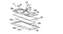
図1に示す本発明の好ましい一実施形態に係る清掃具10は、清掃ヘッド部11の清掃面11aを覆って着脱交換可能に使い捨て用の清掃シート13を取り付けて、例えば床面を被清掃面として清掃作業を行う際に用いられる。本実施形態の清掃具10は、清掃ヘッド部11によって被清掃面を払拭する際に、被清掃面に付着した塵埃や汚れを掻き取って、掻き取った塵埃や汚れを、清掃ヘッド部11の清掃面11aを覆う清掃シート13の広範囲な領域に付着させながら、被清掃面の清掃を行えるようにする機能を備える。   A cleaning tool 10 according to a preferred embodiment of the present invention shown in FIG. 1 covers a cleaning surface 11a of a cleaning head portion 11 and attaches a disposable cleaning sheet 13 so as to be detachable and replaceable. It is used when cleaning work. When the cleaning head 10 wipes the surface to be cleaned by the cleaning head unit 11, the cleaning tool 10 scrapes off dust and dirt adhering to the surface to be cleaned, and removes the dust and dirt from the cleaning head unit 11. A function is provided that allows the surface to be cleaned to be cleaned while adhering to a wide area of the cleaning sheet 13 covering the cleaning surface 11a.

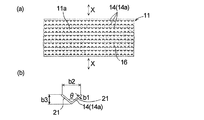
そして、本実施形態の清掃具10は、図2にも示すように、清掃ヘッド部11と、ハンドル部12とを備え、清掃ヘッド部11の下面による清掃面11aを覆って清掃シート13が装着されて、清掃シート13により被清掃面を払拭する清掃具であって、図3に示すように、清掃面11aには、複数の掻取り突起14が突設されている。これらの複数の掻取り突起14は、平面視してV字状部分又は略V字状部分14aを有しており、これらの複数の掻取り突起14の少なくとも一部は、V字状部分又は略V字状部分14aの開放側を主清掃方向Xに向けて配設されている。   And the cleaning tool 10 of this embodiment is provided with the cleaning head part 11 and the handle | steering-wheel part 12, as shown also in FIG. 2, and the cleaning sheet | seat 13 is mounted | worn with covering the cleaning surface 11a by the lower surface of the cleaning head part 11 Then, the cleaning tool wipes the surface to be cleaned with the cleaning sheet 13, and a plurality of scraping protrusions 14 project from the cleaning surface 11 a as shown in FIG. 3. The plurality of scraping projections 14 have a V-shaped portion or a substantially V-shaped portion 14a in plan view, and at least a part of the plurality of scraping projections 14 is a V-shaped portion or The open side of the substantially V-shaped portion 14a is arranged in the main cleaning direction X.

なお、本願明細書で複数の掻取り突起とは、2個以上の掻取り突起を意味するが、清掃ヘッド部が後述の矩形平面視形状を備えている場合には、実用的には、この矩形平面視形状の長辺の両端部付近及び中央部付近に設けられた掻取り突起を含む合計3個以上の多数個の掻取り突起のことを意味する。   In the present specification, a plurality of scraping protrusions means two or more scraping protrusions. However, when the cleaning head portion has a rectangular plan view shape to be described later, practically, It means a large number of scraping protrusions of 3 or more in total including scraping protrusions provided near both ends and the center of the long side of the rectangular plan view shape.

本実施形態では、清掃ヘッド部11は、矩形平面視形状を備えており、この矩形平面視形状の長辺と垂直な方向(図3(a)の上下方向)が主清掃方向Xとなっている。   In the present embodiment, the cleaning head unit 11 has a rectangular plan view shape, and the direction (vertical direction in FIG. 3A) perpendicular to the long side of the rectangular plan view shape is the main cleaning direction X. Yes.

また、本実施形態では、清掃ヘッド部11の矩形平面視形状の両側の長辺に沿った最外周部に設けられた掻取り突起14は、V字状部分又は略V字状部分14aの開放側を主清掃方向Xに向けると共に、開放側を、清掃ヘッド部11の外側に向けて配設されている。   Further, in the present embodiment, the scraping protrusions 14 provided on the outermost peripheral part along the long sides on both sides of the rectangular plan view shape of the cleaning head part 11 are open to the V-shaped part or the substantially V-shaped part 14a. The side is directed in the main cleaning direction X, and the open side is disposed toward the outside of the cleaning head portion 11.

さらに、本実施形態では、掻取り突起14は、清掃ヘッド部11の矩形平面視形状の長手方向に沿って複数列(図3(a)の実施形態では10列)に設けられており、隣接する一対の列のうち、一方の列に配置された掻取り突起14と、他方の列に配置された掻取り突起14とは、V字状部分又は略V字状部分14aの開放側を、清掃ヘッド部11の矩形平面視形状の異なる側の長辺に各々向けて配設されている。   Further, in the present embodiment, the scraping protrusions 14 are provided in a plurality of rows (10 rows in the embodiment of FIG. 3A) along the longitudinal direction of the rectangular shape of the cleaning head portion 11 and adjacent to each other. Among the pair of rows, the scraping protrusions 14 arranged in one row and the scraping projections 14 arranged in the other row are formed on the open side of the V-shaped portion or the substantially V-shaped portion 14a. The cleaning head portion 11 is disposed toward the long sides of the different sides of the rectangular plan view shape.

本実施形態では、清掃具10を構成する清掃ヘッド部11は、図1及び図2に示すように、ヘッド本体15と、ベース体16とからなる。ヘッド本体15は、例えば長辺が200〜500mm程度、短辺が50〜150mm程度の大きさの矩形平面視形状を有するプラスチック製の部材である。ヘッド本体15には、これの上面の中央部分に、ハンドル支持ジョイント部17が一体として設けられている。このハンドル支持ジョイント部17に、ハンドル部12の下端部に設けられた回転ジョイント部18を回転可能に接合することで、当該ハンドル部12を清掃ヘッド部11に対して前後方向のみならず左右方向にも回動させながら、清掃具10による清掃作業を行うことができる。   In this embodiment, the cleaning head part 11 which comprises the cleaning tool 10 consists of the head main body 15 and the base body 16, as shown in FIG.1 and FIG.2. The head main body 15 is a plastic member having a rectangular plan view shape with a long side of about 200 to 500 mm and a short side of about 50 to 150 mm, for example. The head main body 15 is integrally provided with a handle support joint portion 17 at a central portion on the upper surface thereof. A rotational joint 18 provided at the lower end of the handle 12 is rotatably joined to the handle support joint 17 so that the handle 12 is not only in the front-rear direction but also in the left-right direction. In addition, the cleaning work by the cleaning tool 10 can be performed while rotating.

また、ヘッド本体15の上面には、係着スリット19aが形成された柔軟な弾性材料からなる公知のシート保持部19が設けられている。ヘッド本体15の下面側に一体として取り付けられたベース体16の下面(清掃ヘッド部11の下面)による清掃面11aを下方から覆うようにして、清掃シート13を清掃ヘッド11に巻き付けた後に、清掃シート13の端部を、シート保持部19の係着スリット19aに押し込んで係着することにより、清掃シート13を清掃ヘッド部11に着脱交換可能に容易に装着することができる(図1参照)。   Further, a known sheet holding portion 19 made of a flexible elastic material having an engagement slit 19 a is provided on the upper surface of the head body 15. After the cleaning sheet 13 is wound around the cleaning head 11 so as to cover the cleaning surface 11a by the lower surface of the base body 16 (the lower surface of the cleaning head portion 11) attached integrally to the lower surface side of the head body 15, the cleaning is performed. By pushing the end portion of the sheet 13 into the engagement slit 19a of the sheet holding portion 19 and engaging, the cleaning sheet 13 can be easily attached to the cleaning head portion 11 so as to be detachable and replaceable (see FIG. 1). .

ヘッド本体15と共に清掃ヘッド部11を構成するベース体16は、弾性変形可能な合成樹脂材料として、例えばウレタンやEVA(エチレン酢酸ビニル共重合物)樹脂等からなる。ベース体16は、ヘッド本体15よりも一回り大きな矩形平面視形状を備える。ベース体16は、底面部16aと、底面部16aの周縁部に設けられた周壁部16bとからなる。底面部16aは、例えば0.5〜3mm程度の薄い肉厚で形成されている。周壁部16bは、略三角形の断面形状を備える。四方の周壁部16bによって囲まれるベース体16の上面側には、ヘッド本体15が嵌め込まれる凹嵌部16cが形成される。   The base body 16 that constitutes the cleaning head portion 11 together with the head body 15 is made of, for example, urethane or EVA (ethylene vinyl acetate copolymer) resin as an elastically deformable synthetic resin material. The base body 16 has a rectangular plan view shape that is slightly larger than the head body 15. The base body 16 includes a bottom surface portion 16a and a peripheral wall portion 16b provided on the peripheral edge portion of the bottom surface portion 16a. The bottom surface portion 16a is formed with a thin thickness of about 0.5 to 3 mm, for example. The peripheral wall portion 16b has a substantially triangular cross-sectional shape. A concave fitting portion 16c into which the head body 15 is fitted is formed on the upper surface side of the base body 16 surrounded by the four peripheral wall portions 16b.

本実施形態では、図2に示すように、ヘッド本体15の下面とベース体16の底面部16aとの間にクッション材20を介在させて、凹嵌部16cにヘッド本体15を嵌め込み、ヘッド本体15とベース体16とを接着剤等を用いて接着することにより、これらが一体となった清掃ヘッド部11が形成される。   In this embodiment, as shown in FIG. 2, a cushion member 20 is interposed between the lower surface of the head body 15 and the bottom surface portion 16a of the base body 16, and the head body 15 is fitted into the recessed fitting portion 16c. By adhering 15 and the base body 16 using an adhesive or the like, the cleaning head portion 11 in which these are integrated is formed.

ヘッド本体15の下面とベース体16の底面部16aとの間に介在させるクッション材20は、ベース体16よりも柔らかいクッション材料として、例えばスポンジ(材質は例えばウレタンフォーム等)からなる。本実施形態では、クッション材20は、例えばヘッド本体15の下面側に設けられた複数の補強リブ(図示せず)と、ベース体16の底面部16aとの間の隙間を充填するようにして、ヘッド本体15の下面の略全域に亘って装着される。   The cushion material 20 interposed between the lower surface of the head main body 15 and the bottom surface portion 16a of the base body 16 is made of, for example, sponge (the material is urethane foam or the like) as a softer cushion material than the base body 16. In the present embodiment, the cushion material 20 fills a gap between, for example, a plurality of reinforcing ribs (not shown) provided on the lower surface side of the head main body 15 and the bottom surface portion 16 a of the base body 16. The head body 15 is mounted over substantially the entire lower surface.

ヘッド本体15の下面とベース体16の底面部16aとの間にクッション材20を介在させて清掃ヘッド部11が形成されていることで、クッション材20によってベース体16の底面部16aを、これの背面側から面状に支持した状態で押し出すことが可能になる。また、清掃面11aとなる底面部16aの下面を、クッション材20による柔らかな弾性付勢力を介して緩やかに湾曲する湾曲形状に下方に突出させた状態とすることが可能になる。これらによって、例えばハンドル部12から清掃ヘッド部11へ僅かな押圧力しか加えられていない状態では、湾曲する清掃面11aを被清掃面にフィットさせたソフトな感触で清掃作業を行うことが可能になる。また、清掃面11aを被清掃面に押し付けて清掃作業を行うためにハンドル部11から清掃ヘッド部11へ相当の押圧力を加えた状態では、クッション材20は全体に亘ってバランスよく容易に押し潰されて、ソフトなクッション感を伴いながら、清掃シート13によって覆われたベース体16の下面(清掃面11a)を、広範囲に亘って被清掃面にフィットする平坦な面とすることが可能になる。   Since the cushioning material 20 is interposed between the lower surface of the head body 15 and the bottom surface portion 16a of the base body 16, the cleaning head portion 11 is formed. It is possible to extrude in a state where it is supported in a planar shape from the back side. In addition, the bottom surface 16a serving as the cleaning surface 11a can be protruded downward into a curved shape that gently curves through the soft elastic biasing force of the cushion material 20. Thus, for example, in a state where only a slight pressing force is applied from the handle portion 12 to the cleaning head portion 11, it is possible to perform a cleaning operation with a soft feel by fitting the cleaning surface 11a that is curved to the surface to be cleaned. Become. Further, in a state where a considerable pressing force is applied from the handle portion 11 to the cleaning head portion 11 in order to perform the cleaning operation by pressing the cleaning surface 11a against the surface to be cleaned, the cushion material 20 is easily pushed in a balanced manner throughout. While being crushed and accompanied by a soft cushion feeling, the lower surface (cleaning surface 11a) of the base body 16 covered with the cleaning sheet 13 can be a flat surface that fits the surface to be cleaned over a wide range. Become.

また、本実施形態では、ベース体16の周縁部を構成する周壁部16bは、略三角形の断面形状を有していることで、ベース体16の外周部分がベース体16の下面に対して鋭角なテーパー面となる。これによって、例えば壁面と床面との角部分の床面や、壁面の入隅部分の床面に対しても、ベース体16の外周縁部を壁面に当接させつつ、効果的に清掃作業を行うことが可能になる。   Further, in the present embodiment, the peripheral wall portion 16 b constituting the peripheral portion of the base body 16 has a substantially triangular cross-sectional shape, so that the outer peripheral portion of the base body 16 has an acute angle with respect to the lower surface of the base body 16. A tapered surface. Accordingly, for example, the cleaning operation is effectively performed while the outer peripheral edge of the base body 16 is brought into contact with the wall surface, for example, on the floor surface of the corner portion between the wall surface and the floor surface or the floor surface of the corner portion of the wall surface. It becomes possible to do.

さらに、本実施形態では、清掃面11aを覆って清掃ヘッド部11に取り付けられて、塵埃や汚れ等を付着させる清掃シート13としては、例えばオレフィン系極細繊維不織布等の公知の各種の清掃シートを用いることができる。   Furthermore, in this embodiment, as the cleaning sheet 13 that covers the cleaning surface 11a and is attached to the cleaning head unit 11 and adheres dust, dirt, and the like, various known cleaning sheets such as olefin-based ultrafine fiber nonwoven fabrics are used. Can be used.

そして、本実施形態では、ベース体16の下面による清掃ヘッド部11の清掃面11aには、図3(a)、(b)に示すように、平面視してV字状部分又は略V字状部分14aを有する形状として、V字状の平面視形状を有する複数の掻取り突起14が、好ましくは、全ての掻取り突起14の開放側を、主清掃方向Xである、矩形平面視形状を備える清掃ヘッド部11の長辺と垂直な方向に向けてベース体16と一体に配設されている。   In this embodiment, the cleaning surface 11a of the cleaning head portion 11 formed by the lower surface of the base body 16 has a V-shaped portion or a substantially V-shape in plan view as shown in FIGS. 3 (a) and 3 (b). As the shape having the shape-like portion 14a, a plurality of scraping projections 14 having a V-shaped plan view shape are preferably rectangular plan view shapes in which the open side of all the scraping projections 14 is the main cleaning direction X Are disposed integrally with the base body 16 in a direction perpendicular to the long side of the cleaning head section 11.

また、本実施形態では、掻取り突起14は、矩形平面視形状の清掃ヘッド部11の長手方向に沿って10列に設けられており、矩形平面視形状の清掃ヘッド部11の両側の長辺に沿った、両側の最外周の列に配設された掻取り突起14は、V字状部分又は略V字状部分14aの開放側を主清掃方向Xに向けると共に、開放側を、清掃ヘッド部11の外側に向けて配設されている。   In the present embodiment, the scraping protrusions 14 are provided in 10 rows along the longitudinal direction of the rectangular planar view cleaning head portion 11, and the long sides on both sides of the rectangular planar view cleaning head portion 11. The scraping projections 14 arranged in the outermost circumferential rows on both sides are oriented with the open side of the V-shaped part or substantially V-shaped part 14a in the main cleaning direction X, and the open side is set to the cleaning head. It is arranged toward the outside of the part 11.

さらに、本実施形態では、矩形平面視形状の清掃ヘッド部11の長手方向に沿って10列に設けられた掻取り突起14は、隣接する各一対の列うちの一方の列の掻取り突起14と、他方の列の掻取り突起14とが、V字状部分又は略V字状部分14aの開放側を、清掃ヘッド部11の矩形平面視形状の異なる側の長辺に各々向けて配設されている。   Further, in the present embodiment, the scraping protrusions 14 provided in 10 rows along the longitudinal direction of the cleaning head portion 11 having a rectangular plan view shape are the scraping protrusions 14 in one row of each pair of adjacent rows. And the other row of the scraping protrusions 14 are arranged so that the open side of the V-shaped portion or the substantially V-shaped portion 14a faces the long sides of the cleaning head portion 11 on the different sides of the rectangular plan view. Has been.

ここで、本実施形態では、清掃ヘッド部11の清掃面11aに突設された複数の掻取り突起14は、これらの全てが同様の形状を備えている。すなわち、掻取り突起14は、各々、清掃ヘッド部11の清掃面11aから例えば0.5〜5mm程度の高さで突出していると共に、図3(b)に示すように、例えば0.5〜2mm程度の幅b1の一対の直線状の突リブ21を、これらの一端部において接合した、V字状の平面視形状を有している。これにより掻取り突起14は、その全体によってV字状部分又は略V字状部分14aを構成している。   Here, in this embodiment, all of the plurality of scraping protrusions 14 protruding from the cleaning surface 11a of the cleaning head portion 11 have the same shape. That is, the scraping protrusions 14 protrude from the cleaning surface 11a of the cleaning head portion 11 at a height of about 0.5 to 5 mm, for example, and as shown in FIG. It has a V-shaped plan view shape in which a pair of linear protruding ribs 21 having a width b1 of about 2 mm are joined at one end thereof. Thereby, the scraping protrusion 14 constitutes a V-shaped portion or a substantially V-shaped portion 14a as a whole.

また、本実施形態では、掻取り突起14は、V字状部分又は略V字状部分14aを形成する一対の突リブ21の間の角度θが、例えば45〜120°程度となっており、V字状の平面視形状の開放側端部の開口幅b2が、実用的には例えば2〜10mm程度、V字状の平面視形状の接合基端部から開放側端部までの縦幅b3が、実用的には例えば2〜10mm程度の大きさなっている。   In the present embodiment, the scraping protrusion 14 has an angle θ between the pair of protruding ribs 21 forming the V-shaped portion or the substantially V-shaped portion 14a, for example, about 45 to 120 °. The opening width b2 of the open-side end portion of the V-shaped plan view shape is practically about 2 to 10 mm, for example, and the vertical width b3 from the junction base end portion to the open-side end portion of the V-shaped plan view shape. However, the size is practically about 2 to 10 mm, for example.

清掃ヘッド部11の清掃面11aに設けられた複数の掻取り突起14のV字状部分又は略V字状部分14aが、各々上述のような形状や大きさとなっていることにより、清掃シート13で覆われた清掃ヘッド部11の清掃面11aによって被清掃面を払拭する際の摩擦力を受けても、掻取り突起14が変形し難くなって、床にこびりついた塵埃や汚れを、効果的に掻き取ることが可能になる。また、複数の掻取り突起14の少なくとも一部(本実施形態では全部の掻取り突起14)が、V字状部分又は略V字状部分14aの開放側を主清掃方向Xに向けて配設されているので、清掃具10を用いて最も多く行われる清掃の方向である主清掃方向Xに清掃を行った際に、V字状部分又は略V字状部分14aの開放側から、一対の突リブ21が接合する基端部側に向けて、掻き取った塵埃や汚れを集約しながら、清掃面11aの全体に分散して配置された各掻取り突起14のV字状部分又は略V字状部分14aの基端部の付近に、掻き取った塵埃や汚れを各々捕捉することが可能になる。これによって、清掃ヘッド部11の清掃面11aを覆って装着された清掃シート13の更に広範囲な領域に、掻き取った塵埃や汚れを効率良く付着させることが可能になる。   Since the V-shaped portions or substantially V-shaped portions 14a of the plurality of scraping projections 14 provided on the cleaning surface 11a of the cleaning head portion 11 have the above-described shapes and sizes, the cleaning sheet 13 Even if the cleaning surface 11a of the cleaning head unit 11 covered with the cleaning surface 11a receives a frictional force when wiping the surface to be cleaned, the scraping projection 14 is difficult to be deformed and effectively removes dust and dirt stuck to the floor. It can be scraped off. Further, at least some of the plurality of scraping protrusions 14 (all scraping protrusions 14 in the present embodiment) are arranged with the open side of the V-shaped portion or the substantially V-shaped portion 14a facing the main cleaning direction X. Therefore, when cleaning is performed in the main cleaning direction X, which is the cleaning direction most frequently performed using the cleaning tool 10, a pair of V-shaped portions or substantially V-shaped portions 14a are opened from the open side. While collecting dust and dirt scraped off toward the base end side where the protruding ribs 21 are joined, the V-shaped portions or substantially V-shaped portions of the respective scraping protrusions 14 distributed throughout the cleaning surface 11a are gathered. It is possible to capture the dust and dirt that have been scraped off in the vicinity of the base end portion of the character-shaped portion 14a. As a result, it is possible to efficiently attach the scraped dust and dirt to a wider area of the cleaning sheet 13 mounted so as to cover the cleaning surface 11a of the cleaning head unit 11.

したがって、本実施形態の清掃具10によれば、被清掃面の塵埃や汚れを効果的に掻き取ることが可能になると共に、清掃ヘッド部11の清掃面11aを覆って装着された清掃シート13の更に広範囲な領域に、掻き取った塵埃や汚れを効率良く付着させながら被清掃面の清掃を行うことが可能になる。   Therefore, according to the cleaning tool 10 of the present embodiment, it is possible to effectively scrape dust and dirt on the surface to be cleaned, and the cleaning sheet 13 mounted so as to cover the cleaning surface 11a of the cleaning head portion 11. It is possible to clean the surface to be cleaned while efficiently adhering the scraped dust and dirt to a wider area.

また、本実施形態の清掃具10によれば、清掃ヘッド部11の両側の長辺に沿った最外周部の掻取り突起14が、V字状部分又は略V字状部分14aの開放側を主清掃方向Xに向けると共に、開放側を、清掃ヘッド部11の外側に向けて配設されているので、清掃具10の清掃ヘッド部11を主清掃方向Xに移動させて清掃を行った際に、当該最外周部の各掻取り突起14のV字状部分を構成する一対の突リブ21の内側に塵埃や汚れを集めることで、清掃ヘッド部11の両側の長辺に沿った最外周部分に、塵埃や汚れを効率良く集めることが可能になる。   Moreover, according to the cleaning tool 10 of this embodiment, the scraping protrusion 14 of the outermost peripheral part along the long side of the both sides of the cleaning head part 11 is the open side of the V-shaped part or the substantially V-shaped part 14a. The main cleaning direction X is directed toward the main cleaning direction X, and the opening side is disposed toward the outside of the cleaning head portion 11. Therefore, when the cleaning head portion 11 of the cleaning tool 10 is moved in the main cleaning direction X for cleaning. Further, by collecting dust and dirt inside the pair of protruding ribs 21 constituting the V-shaped portion of each scraping protrusion 14 of the outermost peripheral portion, the outermost periphery along the long sides on both sides of the cleaning head portion 11 is collected. It is possible to efficiently collect dust and dirt on the part.

さらに、本実施形態の清掃具10によれば、隣接する各一対の列うちの一方の列に配置された掻取り突起14と、他方の列に配置された掻取り突起14とが、V字状部分又は略V字状部分14aの開放側を、清掃ヘッド部11の矩形平面視形状の異なる側の長辺に各々向けて配設されているので、清掃具10の清掃ヘッド部11を主清掃方向Xに往復移動させて清掃を行った際に、V字状部分又は略V字状部分14aの開放側が主清掃方向Xの往復両方向に開口しているため、掻き取った塵埃や汚れを更に効率良く清掃シート13に付着させながら被清掃面の清掃を行うことが可能になる。   Furthermore, according to the cleaning tool 10 of the present embodiment, the scraping protrusions 14 arranged in one row of each pair of adjacent rows and the scraping projections 14 arranged in the other row are V-shaped. Since the open side of the V-shaped portion or the substantially V-shaped portion 14a is arranged toward the long sides of the cleaning head portion 11 on different sides of the rectangular plan view, the cleaning head portion 11 of the cleaning tool 10 is mainly used. When cleaning is performed by reciprocating in the cleaning direction X, the open side of the V-shaped portion or the substantially V-shaped portion 14a opens in both directions of the main cleaning direction X. Furthermore, the surface to be cleaned can be cleaned while being attached to the cleaning sheet 13 efficiently.

図4(a)、(b)は、本実施形態の清掃具10の清掃ヘッド部11の他の形態を例示するものである。図4(a)に示す形態の清掃ヘッド部11は、ベース体16の下面による清掃面11aに、図3(b)に示すV字状の平面視形状を備える複数の掻取り突起14を、隣接する各一対の列のうちの一方の列に配置された掻取り突起14と、他方の列に配置された掻取り突起14とを、V字状部分又は略V字状部分14aの開放側を異なる側の長辺に各々向けて配設すると共に、清掃ヘッド部11の矩形平面視形状の長手方向の位置をずらして互い違いに千鳥状に配置したものである。図4(b)に示す形態の清掃ヘッド部11は、ベース体16の下面による清掃面11aに、図3(b)に示すV字状の平面視形状を備える複数の掻取り突起14を、図4(a)に示す形態から、更に清掃ヘッド部11の矩形平面視形状の長手方向に沿って順に、V字状部分又は略V字状部分14aの開放側が交互に異なる側の長辺に各々向くように配置したものである。   4A and 4B illustrate other forms of the cleaning head portion 11 of the cleaning tool 10 of the present embodiment. The cleaning head portion 11 in the form shown in FIG. 4A has a plurality of scraping projections 14 having a V-shaped plan view shape shown in FIG. The scraping projections 14 arranged in one row of each pair of adjacent rows and the scraping projections 14 arranged in the other row are connected to the open side of the V-shaped portion or the substantially V-shaped portion 14a. Are arranged so as to be directed to the long sides on different sides, and the positions of the cleaning head portion 11 in the rectangular plan view are shifted in a staggered manner in a staggered manner. The cleaning head portion 11 in the form shown in FIG. 4B has a plurality of scraping protrusions 14 having a V-shaped plan view shape shown in FIG. From the configuration shown in FIG. 4 (a), the open side of the V-shaped portion or the substantially V-shaped portion 14a is alternately changed to the longer side in order along the longitudinal direction of the rectangular plan view shape of the cleaning head portion 11. They are arranged to face each other.

図4(a)、(b)に示す形態の清掃ヘッド部11を備える清掃具10によっても、上述と同様の作用効果が奏される。また、図4(a)に示す形態の清掃ヘッド部11によれば、隣接する一方の列に配置された掻取り突起14と、他方の列に配置された掻取り突起14とが、開放側を異なる側の長辺に各々向けて配設されていると共に、互い違いに千鳥状に配置されているので、清掃具10により主清掃方向Xに清掃を行った際に、各一対の掻取り突起14の間から後ろ側へ逃げた粉塵や汚れを、千鳥状にずれて配置されている後ろ側の突起14に接触させて掻取ることが可能になって、清掃効率を更に向上させることが可能になる。また図4(b)に示す形態の清掃ヘッド部11によれば、各一対の掻取り突起14の間から後ろ側へ逃げた粉塵や汚れを、千鳥状にずれて配置されている後ろ側の突起14に接触させて掻取ることが可能になることに加えて、各々の掻取り突起14のV字状部分又は略V字状部分14aを構成する一対の突リブ21の内側に、塵埃や汚れを更に効率よく集めることが可能になる。   Effects similar to those described above are also achieved by the cleaning tool 10 including the cleaning head portion 11 having the configuration shown in FIGS. 4 (a) and 4 (b). Moreover, according to the cleaning head part 11 of the form shown to Fig.4 (a), the scraping protrusion 14 arrange | positioned at one adjacent row | line | column and the scraping protrusion 14 arrange | positioned at the other row | line | column are open side. Are arranged toward the long sides on different sides and are alternately arranged in a staggered manner, so that when the cleaning tool 10 performs cleaning in the main cleaning direction X, each pair of scraping protrusions Dust and dirt that escaped from between 14 to the back side can be scraped by making contact with the rear-side protrusion 14 arranged in a staggered manner, thereby further improving the cleaning efficiency. become. Moreover, according to the cleaning head part 11 of the form shown in FIG.4 (b), the dust and dirt which escaped to the back side from between each pair of scraping protrusions 14 are shifted in a zigzag pattern and arranged on the back side. In addition to being able to be scraped by being brought into contact with the protrusions 14, dust or dirt is formed inside the pair of protruding ribs 21 constituting the V-shaped part or the substantially V-shaped part 14 a of each scraping protrusion 14. It becomes possible to collect dirt more efficiently.

図5(a)は、本実施形態の清掃具10の清掃ヘッド部11のさらに他の形態を例示するものである。図5(a)に示す清掃ヘッド部11は、当該清掃ヘッド部11のベース体16の下面による清掃面11aに、図3(a)に示す清掃ヘッド部11の清掃面11aに設けられたV字状の平面視形状を有する複数の掻取り突起14に代えて、図5(b)に示すような、3本の突リブ22によるY字状の複数の掻取り突起23を突設させたものである。   FIG. 5A illustrates still another form of the cleaning head portion 11 of the cleaning tool 10 of the present embodiment. The cleaning head portion 11 shown in FIG. 5A is provided with a cleaning surface 11a formed on the lower surface of the base body 16 of the cleaning head portion 11 on the cleaning surface 11a of the cleaning head portion 11 shown in FIG. Instead of the plurality of scraping projections 14 having a letter-like shape in plan view, a plurality of Y-shaped scraping projections 23 by three protruding ribs 22 are provided so as to project as shown in FIG. Is.

すなわち、図5(a)に示す清掃ヘッド部11では、清掃ヘッド部11の清掃面11aに突設された複数の掻取り突起23は、各々、図5(b)に示すように、3本の突リブ22を、これらの一端部において接合することで、Y字状の平面視形状を有している。また3本の突リブ22のうちの隣接する各一対の突リブ22によって、V字状部分又は略V字状部分23aが構成されている。   That is, in the cleaning head portion 11 shown in FIG. 5A, the plurality of scraping protrusions 23 protruding from the cleaning surface 11a of the cleaning head portion 11 are each three as shown in FIG. These projecting ribs 22 are joined at their one ends to have a Y-shaped plan view. A pair of adjacent ribs 22 out of the three ribs 22 constitutes a V-shaped portion or a substantially V-shaped portion 23a.

図5(a)に示す清掃ヘッド部11を備える清掃具10によっても、図3(a)に示す清掃ヘッド部11を備える清掃具10と略同様の作用効果が奏される。   Also with the cleaning tool 10 provided with the cleaning head part 11 shown in FIG. 5A, substantially the same operational effects as the cleaning tool 10 provided with the cleaning head part 11 shown in FIG.

図6(a)、(b)は、本実施形態の清掃具10の清掃ヘッド部11のさらに他の形態を例示するものである。図6(a)に示す形態の清掃ヘッド部11は、ベース体16の下面による清掃面11aに、図5(b)に示すY字状の平面視形状を備える複数の掻取り突起23を、隣接する各一対の列のうちの一方の列に配置された掻取り突起23と、他方の列に配置された掻取り突起23とを、V字状部分又は略V字状部分23aの開放側を異なる側の長辺に各々向けて配設すると共に、清掃ヘッド部11の矩形平面視形状の長手方向の位置をずらして互い違いに千鳥状に配置したものである。図6(b)に示す清掃ヘッド部11は、ベース体16の下面による清掃面11aに、図5(b)に示すY字状の平面視形状を備える複数の掻取り突起23を、図6(a)に示す形態から、更に清掃ヘッド部11の矩形平面視形状の長手方向に沿って順に、V字状部分又は略V字状部分23aの開放側を90度ずつ方向を変えて、ヘッド本体15の長辺側と短辺側の両方に向くように配置したものである。   FIGS. 6A and 6B illustrate still another form of the cleaning head portion 11 of the cleaning tool 10 of the present embodiment. The cleaning head portion 11 in the form shown in FIG. 6A has a plurality of scraping protrusions 23 having a Y-shaped plan view shape shown in FIG. The scraping projections 23 arranged in one row of each pair of adjacent rows and the scraping projections 23 arranged in the other row are connected to the open side of the V-shaped portion or the substantially V-shaped portion 23a. Are arranged so as to be directed to the long sides on different sides, and the positions of the cleaning head portion 11 in the rectangular plan view are shifted in a staggered manner in a staggered manner. The cleaning head portion 11 shown in FIG. 6B has a plurality of scraping projections 23 having a Y-shaped plan view shape shown in FIG. From the form shown in (a), the direction of the open side of the V-shaped portion or the substantially V-shaped portion 23a is changed by 90 degrees in order along the longitudinal direction of the rectangular plan view shape of the cleaning head portion 11, and the head is changed. The main body 15 is arranged so as to face both the long side and the short side.

図6(a)や図6(b)に示す清掃ヘッド部11を備える清掃具10によっても、図4(a)や図4(b)に示す清掃ヘッド部11の備える清掃具10と略同様の作用効果が奏される。   The cleaning tool 10 provided with the cleaning head part 11 shown in FIGS. 6A and 6B is also substantially the same as the cleaning tool 10 provided in the cleaning head part 11 shown in FIGS. 4A and 4B. The effect of is produced.

図7(a)は、本実施形態の清掃具10の清掃ヘッド部11のさらに他の形態を例示するものである。図7(a)に示す清掃ヘッド部11は、当該清掃ヘッド部11のベース体16の下面による清掃面11aに、図3(a)に示す清掃ヘッド部11の清掃面11aに設けられたV字状の平面視形状を有する複数の掻取り突起14に代えて、図7(b)に示すような、4本の突リブ24によるX字状の複数の掻取り突起25を突設させたものである。   FIG. 7A illustrates still another form of the cleaning head portion 11 of the cleaning tool 10 of the present embodiment. The cleaning head portion 11 shown in FIG. 7A has a V provided on the cleaning surface 11a of the cleaning head portion 11 shown in FIG. Instead of the plurality of scraping protrusions 14 having a letter-like shape in plan view, a plurality of X-shaped scraping protrusions 25 by four protruding ribs 24 as shown in FIG. Is.

すなわち、図7(a)に示す清掃ヘッド部11では、清掃ヘッド部11の清掃面11aに突設された複数の掻取り突起25は、各々、図7(b)に示すように、4本の突リブ24を、これらの一端部において接合することで、X字状の平面視形状を有している。また4本の突リブ24のうちの隣接する各一対の突リブ24によって、V字状部分又は略V字状部分25aが構成されている。   That is, in the cleaning head unit 11 shown in FIG. 7A, the plurality of scraping projections 25 protruding from the cleaning surface 11a of the cleaning head unit 11 are each four as shown in FIG. 7B. These projecting ribs 24 are joined at one end thereof to have an X-shaped plan view shape. A pair of adjacent ribs 24 out of the four ribs 24 constitutes a V-shaped portion or a substantially V-shaped portion 25a.

図7(a)に示す清掃ヘッド部11を備える清掃具10によっても、図3(a)に示す清掃ヘッド部11を備える清掃具10と略同様の作用効果が奏される。さらに矩形平面視形状の短辺と垂直な方向を主清掃方向として、被清掃面の清掃が行われる場合であっても、短辺を向いたV字状部分又は略V字状部分25aの開放側が当該主清掃方向に向けて配設されているため、長辺と垂直な方向を主清掃方向Xとして被清掃面の清掃が行われる場合と略同様の作用効果が奏される。   Also with the cleaning tool 10 provided with the cleaning head part 11 shown in FIG. 7A, substantially the same operational effects as the cleaning tool 10 provided with the cleaning head part 11 shown in FIG. Furthermore, even when the surface to be cleaned is cleaned with the direction perpendicular to the short side of the rectangular plan view as the main cleaning direction, the V-shaped portion or the substantially V-shaped portion 25a facing the short side is opened. Since the side is arranged in the main cleaning direction, the same effect as the case where the surface to be cleaned is cleaned with the direction perpendicular to the long side as the main cleaning direction X is achieved.

図8は、本実施形態の清掃具10の清掃ヘッド部11のさらに他の形態を例示するものである。図8に示す清掃ヘッド部11は、ベース体16の下面による清掃面11aに、図7(b)に示すX字状の平面視形状を備える複数の掻取り突起25を、隣接する各一対の列のうちの一方の列に配置された掻取り突起25と、他方の列に配置された掻取り突起25とを、V字状部分又は略V字状部分25aの開放側を異なる側の長辺に各々向けて配設すると共に、清掃ヘッド部11の矩形平面視形状の長手方向の位置をずらして互い違いに千鳥状に配置したものである。   FIG. 8 illustrates still another form of the cleaning head portion 11 of the cleaning tool 10 of the present embodiment. The cleaning head portion 11 shown in FIG. 8 has a plurality of scraping protrusions 25 having an X-shaped plan view shape shown in FIG. The scraping projections 25 arranged in one of the columns and the scraping projections 25 arranged in the other column are different from each other in the V-shaped portion or the open side of the substantially V-shaped portion 25a. While arrange | positioning toward each edge | side, the position of the longitudinal direction of the rectangular planar view shape of the cleaning head part 11 is shifted, and it arrange | positions alternately at zigzag form.

図8に示す清掃ヘッド部11を備える清掃具10によっても、図4(a)に示す清掃ヘッド部11を備える清掃具10と略同様の作用効果が奏される。   Also with the cleaning tool 10 provided with the cleaning head part 11 shown in FIG. 8, the effect substantially the same as the cleaning tool 10 provided with the cleaning head part 11 shown to Fig.4 (a) is show | played.

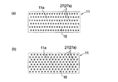
図9(a)は、本実施形態の清掃具10の清掃ヘッド部11のさらに他の形態を例示するものである。図9(a)に示す清掃ヘッド部11は、当該清掃ヘッド部11のベース体16の下面による清掃面11aに、図3(a)に示す清掃ヘッド部11の清掃面11aに設けられたV字状の平面視形状を有する複数の掻取り突起14に代えて、図9(b)に示すような、5本の突リブ26によるヒトデ状の複数の掻取り突起27を突設させたものである。   FIG. 9A illustrates still another form of the cleaning head portion 11 of the cleaning tool 10 of the present embodiment. The cleaning head portion 11 shown in FIG. 9A has a V provided on the cleaning surface 11a of the cleaning head portion 11 shown in FIG. Instead of the plurality of scraping projections 14 having a letter-like shape in plan view, a plurality of starfish-shaped scraping projections 27 with five projecting ribs 26 project as shown in FIG. 9B. It is.

すなわち、図9(a)に示す清掃ヘッド部11では、清掃ヘッド部11の清掃面11aに突設された複数の掻取り突起27は、各々、図9(b)に示すように、5本の突リブ26を、これらの一端部において接合することで、ヒトデ状の平面視形状を有している。また5本の突リブ26のうちの隣接する各一対の突リブ26によって、V字状部分又は略V字状部分27aが構成されている。   That is, in the cleaning head portion 11 shown in FIG. 9A, the plurality of scraping projections 27 protruding from the cleaning surface 11a of the cleaning head portion 11 are each five as shown in FIG. 9B. These projecting ribs 26 are joined at one end thereof to have a starfish-like plan view shape. A pair of adjacent protruding ribs 26 of the five protruding ribs 26 constitutes a V-shaped portion or a substantially V-shaped portion 27a.

図9(a)に示す清掃ヘッド部11を備える清掃具10によっても、図3(a)に示す清掃ヘッド部11を備える清掃具10と略同様の作用効果が奏される。   Also with the cleaning tool 10 provided with the cleaning head part 11 shown in FIG. 9A, substantially the same operational effects as the cleaning tool 10 provided with the cleaning head part 11 shown in FIG.

図10(a)、(b)は、本実施形態の清掃具10の清掃ヘッド部11のさらに他の形態を例示するものである。図10(a)に示す清掃ヘッド部11は、ベース体16の下面による清掃面11aに、図9(b)に示すヒトデ状の平面視形状を備える複数の掻取り突起27を、隣接する各一対の列のうちの一方の列に配置された掻取り突起27と、他方の列に配置された掻取り突起27とを、V字状部分又は略V字状部分27aの開放側を異なる側の長辺に各々向けて配設すると共に、清掃ヘッド部11の矩形平面視形状の長手方向の位置をずらして互い違いに千鳥状に配置したものである。図10(b)に示す清掃ヘッド部11は、ベース体16の下面による清掃面11aに、図9(b)に示すヒトデ状の平面視形状を備える複数の掻取り突起27を、図9(a)に示す形態から、更に清掃ヘッド部11の矩形平面視形状の長手方向に沿って順に、V字状部分又は略V字状部分27aの開放側を18度ずつ方向を変えて、開放側が多方向に向くように配置したものである。   FIGS. 10A and 10B illustrate still another form of the cleaning head portion 11 of the cleaning tool 10 of the present embodiment. The cleaning head portion 11 shown in FIG. 10A has a plurality of scraping protrusions 27 each having a starfish-like plan view shape shown in FIG. The scraping protrusions 27 arranged in one row of the pair of rows and the scraping projections 27 arranged in the other row are separated from the open side of the V-shaped portion or the substantially V-shaped portion 27a. The cleaning head portion 11 is arranged in a staggered manner by shifting the position in the longitudinal direction of the rectangular plan view of the cleaning head portion 11. The cleaning head portion 11 shown in FIG. 10B has a plurality of scraping projections 27 having a starfish-like plan view shape shown in FIG. 9B on the cleaning surface 11a formed by the lower surface of the base body 16. FIG. From the form shown in a), the opening side of the V-shaped portion or the substantially V-shaped portion 27a is changed by 18 degrees in order along the longitudinal direction of the rectangular plan view shape of the cleaning head portion 11 so that the opening side is It is arranged so as to face in multiple directions.

図10(a)や図10(b)に示す清掃ヘッド部11を備える清掃具10によっても、図4(a)や図4(b)に示す清掃ヘッド部11を備える清掃具10と略同様の作用効果が奏される。   The cleaning tool 10 including the cleaning head unit 11 illustrated in FIGS. 10A and 10B is substantially the same as the cleaning tool 10 including the cleaning head unit 11 illustrated in FIGS. 4A and 4B. The effect of is produced.

なお、本発明は上記実施形態に限定されることなく種々の変更が可能である。例えば、矩形平面視形状を備えている清掃ヘッド部は、この矩形平面視形状の長辺、短辺が曲線であっても良い。また、矩形平面視形状には正方形も含まれてもよく、この場合には、前記矩形平面視形状の長辺は、正方形のいずれかの辺を任意に選択できる。更に清掃ヘッド部は、矩形平面視形状を備えている必要は必ずしもなく、長円形状や楕円形状等の、清掃作業に適したその他の種々の平面視形状を備えていても良い。また、最も多く行われる清掃の方向である主清掃方向は、清掃ヘッド部の長手方向と垂直な方向となっている必要は必ずしもない。さらに、V字状部分又は略V字状部分の開放側を主清掃方向に向けた掻取り突起は、複数の掻取り突起の全てである必要は必ずしもなく、複数の掻取り突起の少なくとも一部であれば良い。   The present invention is not limited to the above-described embodiment, and various modifications can be made. For example, a cleaning head portion having a rectangular plan view shape may have curved long and short sides. In addition, a square shape may be included in the rectangular plan view shape, and in this case, any one side of the square can be arbitrarily selected as the long side of the rectangular plan view shape. Furthermore, the cleaning head portion does not necessarily have a rectangular plan view shape, and may have other various plan view shapes suitable for cleaning work, such as an oval shape or an oval shape. The main cleaning direction, which is the most frequently performed cleaning direction, does not necessarily have to be a direction perpendicular to the longitudinal direction of the cleaning head portion. Further, the scraping projections with the open side of the V-shaped portion or the substantially V-shaped portion facing the main cleaning direction do not necessarily have to be all of the plurality of scraping projections, and at least a part of the plurality of scraping projections If it is good.

また、複数の掻取り突起のV字状部分又は略V字状部分は、V字状の平面視形状を有している必要は必ずしもなく、略V字状の平面視形状を有していても良い。略V字状の平面形視状としては、例えば図11に示すような、V字形状を形成する一対の直線状の突リブ21’を、開放側とは反対側の基端部において離間させると共に、基端部の離間部分に、柱状リブ28を配置したものを採用することもできる。このような略V字状部分を含む複数の掻取り突起14’によっても、上述と同様の作用効果が奏される。   Further, the V-shaped portions or the substantially V-shaped portions of the plurality of scraping protrusions do not necessarily have a V-shaped plan view shape, and have a substantially V-shaped plan view shape. Also good. For example, as shown in FIG. 11, a pair of linear protruding ribs 21 'forming a V shape are separated from each other at the base end opposite to the open side. In addition, it is possible to employ a structure in which the columnar ribs 28 are arranged in the separated portion of the base end. The plurality of scraping protrusions 14 ′ including such a substantially V-shaped portion can also provide the same effects as described above.

10 清掃具
11 清掃ヘッド部
11a 清掃面
12 ハンドル部
13 清掃シート
14,23,25,27 掻取り突起
14a,23a,25a,27a V字状部分又は略V字状部分
15 ヘッド本体
16 ベース体
20 クッション材
21,22,24,26 突リブ
X 主清掃方向
DESCRIPTION OF SYMBOLS 10 Cleaning tool 11 Cleaning head part 11a Cleaning surface 12 Handle part 13 Cleaning sheet 14,23,25,27 Scraping protrusion 14a, 23a, 25a, 27a V-shaped part or substantially V-shaped part 15 Head main body 16 Base body 20 Cushion material 21, 22, 24, 26 Projection rib X Main cleaning direction

Claims (5)

清掃ヘッド部と、ハンドル部とを備え、前記清掃ヘッド部の下面による清掃面を覆って清掃シートが装着されて、該清掃シートにより被清掃面を払拭する清掃具であって、
前記清掃面には、複数の掻取り突起が突設されており、該複数の掻取り突起は、平面視してV字状部分又は略V字状部分を有しており、該複数の掻取り突起の少なくとも一部は、前記V字状部分又は略V字状部分の開放側を主清掃方向に向けて配設されている清掃具。
A cleaning tool comprising a cleaning head part and a handle part, wherein a cleaning sheet is mounted to cover a cleaning surface by a lower surface of the cleaning head part, and the surface to be cleaned is wiped by the cleaning sheet,
The cleaning surface is provided with a plurality of scraping projections, and the plurality of scraping projections have a V-shaped portion or a substantially V-shaped portion in plan view, and the plurality of scraping projections. At least a part of the take-up projection is a cleaning tool arranged with the open side of the V-shaped part or the substantially V-shaped part facing the main cleaning direction.
前記清掃ヘッド部は、矩形平面視形状を備えており、該矩形平面視形状の長辺と垂直な方向が主清掃方向となっている請求項1記載の清掃具。   The cleaning tool according to claim 1, wherein the cleaning head portion has a rectangular plan view shape, and a direction perpendicular to a long side of the rectangular plan view shape is a main cleaning direction. 前記清掃ヘッド部の前記矩形平面視形状の両側の長辺に沿った最外周部に設けられた前記掻取り突起は、前記V字状部分又は略V字状部分の開放側を主清掃方向に向けると共に、開放側を、前記清掃ヘッド部の外側に向けて配設されている請求項2記載の清掃具。   The scraping projections provided on the outermost peripheral part along the long sides on both sides of the rectangular plan view shape of the cleaning head part have the open side of the V-shaped part or the substantially V-shaped part in the main cleaning direction. The cleaning tool according to claim 2, wherein the cleaning tool is disposed so that the open side faces the outside of the cleaning head portion. 前記掻取り突起は、前記清掃ヘッド部の前記矩形平面視形状の長手方向に沿って複数列に設けられており、隣接する各一対の列のうちの一方の列に配置された前記掻取り突起と、他方の列に配置された前記掻取り突起とは、前記V字状部分又は略V字状部分の開放側を、前記清掃ヘッド部の前記矩形平面視形状の異なる側の長辺に各々向けて配設されている請求項2又は3記載の清掃具。   The scraping protrusions are provided in a plurality of rows along the longitudinal direction of the rectangular plan view shape of the cleaning head portion, and the scraping protrusions arranged in one row of each pair of adjacent rows And the scraping protrusions arranged in the other row, the open side of the V-shaped portion or the substantially V-shaped portion, respectively, on the long side of the cleaning head portion on the different side of the rectangular plan view shape The cleaning tool of Claim 2 or 3 arrange | positioned. 隣接する各一対の列のうちの一方の列に配置された前記掻取り突起と、他方の列に配置された前記掻取り突起とは、前記清掃ヘッド部の前記矩形平面視形状の長手方向の位置をずらして互い違いに千鳥状に配置されている請求項4記載の清掃具。   The scraping protrusions arranged in one row of each pair of adjacent rows and the scraping protrusions arranged in the other row are arranged in the longitudinal direction of the rectangular plan view shape of the cleaning head portion. The cleaning tool according to claim 4, wherein the cleaning tool is arranged in a staggered manner by shifting the position.
JP2012033077A 2012-02-17 2012-02-17 Cleaning implement Pending JP2013169237A (en)

Priority Applications (1)

Application Number Priority Date Filing Date Title
JP2012033077A JP2013169237A (en) 2012-02-17 2012-02-17 Cleaning implement

Applications Claiming Priority (1)

Application Number Priority Date Filing Date Title
JP2012033077A JP2013169237A (en) 2012-02-17 2012-02-17 Cleaning implement

Publications (1)

Publication Number Publication Date
JP2013169237A true JP2013169237A (en) 2013-09-02

Family

ID=49263617

Family Applications (1)

Application Number Title Priority Date Filing Date
JP2012033077A Pending JP2013169237A (en) 2012-02-17 2012-02-17 Cleaning implement

Country Status (1)

Country Link
JP (1) JP2013169237A (en)

Cited By (5)

* Cited by examiner, † Cited by third party
Publication number Priority date Publication date Assignee Title
JP2017035990A (en) * 2015-08-10 2017-02-16 本田技研工業株式会社 Panel structure
JP2018086043A (en) * 2016-11-28 2018-06-07 株式会社テラモト Cleaning tool
JP2018198686A (en) * 2017-05-26 2018-12-20 レック株式会社 Connection structure of mop head and operation rod, and mop
WO2018230293A1 (en) 2017-06-14 2018-12-20 大王製紙株式会社 Cleaning tool
JP2020074931A (en) * 2018-11-07 2020-05-21 株式会社南武 Cleaning tool and member for cleaning tool

Citations (7)

* Cited by examiner, † Cited by third party
Publication number Priority date Publication date Assignee Title
JPH0678872A (en) * 1992-09-04 1994-03-22 Hookii:Kk Wiping cleaning device
JPH09135799A (en) * 1995-11-13 1997-05-27 Dainippon Jochugiku Co Ltd Wiping tool
JPH1033445A (en) * 1996-07-22 1998-02-10 Dainippon Jochugiku Co Ltd Cleaner
JP2002238821A (en) * 2001-02-13 2002-08-27 Satoshi Shintani Cleaning sheet
JP2006518223A (en) * 2003-02-19 2006-08-10 ザ プロクター アンド ギャンブル カンパニー Cleaning sheet
JP2008511409A (en) * 2004-09-01 2008-04-17 アンガー・マーケティング・インターナショナル・エルエルシー Floor cleaning mop with dust collecting projections
WO2009085624A1 (en) * 2007-12-27 2009-07-09 3M Innovative Properties Company Cleaning tool forming a three dimensional cleaning surface

Patent Citations (7)

* Cited by examiner, † Cited by third party
Publication number Priority date Publication date Assignee Title
JPH0678872A (en) * 1992-09-04 1994-03-22 Hookii:Kk Wiping cleaning device
JPH09135799A (en) * 1995-11-13 1997-05-27 Dainippon Jochugiku Co Ltd Wiping tool
JPH1033445A (en) * 1996-07-22 1998-02-10 Dainippon Jochugiku Co Ltd Cleaner
JP2002238821A (en) * 2001-02-13 2002-08-27 Satoshi Shintani Cleaning sheet
JP2006518223A (en) * 2003-02-19 2006-08-10 ザ プロクター アンド ギャンブル カンパニー Cleaning sheet
JP2008511409A (en) * 2004-09-01 2008-04-17 アンガー・マーケティング・インターナショナル・エルエルシー Floor cleaning mop with dust collecting projections
WO2009085624A1 (en) * 2007-12-27 2009-07-09 3M Innovative Properties Company Cleaning tool forming a three dimensional cleaning surface

Cited By (9)

* Cited by examiner, † Cited by third party
Publication number Priority date Publication date Assignee Title
JP2017035990A (en) * 2015-08-10 2017-02-16 本田技研工業株式会社 Panel structure
US10967917B2 (en) 2015-08-10 2021-04-06 Honda Motor Co., Ltd. Panel structure
JP2018086043A (en) * 2016-11-28 2018-06-07 株式会社テラモト Cleaning tool
JP7008936B2 (en) 2016-11-28 2022-01-25 株式会社テラモト Cleaning tool
JP2018198686A (en) * 2017-05-26 2018-12-20 レック株式会社 Connection structure of mop head and operation rod, and mop
JP6990043B2 (en) 2017-05-26 2022-01-12 レック株式会社 Connection structure between mop head and operation rod and mop
WO2018230293A1 (en) 2017-06-14 2018-12-20 大王製紙株式会社 Cleaning tool
US11317781B2 (en) 2017-06-14 2022-05-03 Daio Paper Corporation Cleaning tool
JP2020074931A (en) * 2018-11-07 2020-05-21 株式会社南武 Cleaning tool and member for cleaning tool

Similar Documents

Publication Publication Date Title
US7386907B2 (en) Cleaning sheet
US7779501B2 (en) Mop having scrubbing area
JP5681239B2 (en) Cleaning tool
JP2013169237A (en) Cleaning implement
JP4662454B2 (en) Cleaning tool
JP4808450B2 (en) Cleaning tool
JP5901910B2 (en) Cleaning tool
JP2012147958A (en) Cleaning tool
JP5791396B2 (en) Processing equipment
JP3027345B2 (en) Cleaning tools
JP3560399B2 (en) Wiping tools
JP2006271644A (en) Washing tool
JP3948820B2 (en) Cleaning sheet
JP3625931B2 (en) Cleaning tool
JP2004073678A (en) Cleaner
JP2016043190A (en) Treating material holding head and treating device
JP6524168B2 (en) Cleaning tool
JP3170447U (en) Cleaning tool
JP2019013387A (en) Cleaning tool
JP3224746B2 (en) Cleaning tools
JP2005287531A (en) Sponge cleaner
JP6297831B2 (en) Cleaning sheet and cleaning tool having the same
JP3163139U (en) Super fine fiber cloth for flooring wiper
JP5631140B2 (en) Cleaning tool
JP3128788U (en) Three-dimensional gloves that collect dust

Legal Events

Date Code Title Description
A621 Written request for application examination

Free format text: JAPANESE INTERMEDIATE CODE: A621

Effective date: 20141204

A977 Report on retrieval

Free format text: JAPANESE INTERMEDIATE CODE: A971007

Effective date: 20150910

A131 Notification of reasons for refusal

Free format text: JAPANESE INTERMEDIATE CODE: A131

Effective date: 20150929

A521 Written amendment

Free format text: JAPANESE INTERMEDIATE CODE: A523

Effective date: 20151127

RD03 Notification of appointment of power of attorney

Free format text: JAPANESE INTERMEDIATE CODE: A7423

Effective date: 20151225

A02 Decision of refusal

Free format text: JAPANESE INTERMEDIATE CODE: A02

Effective date: 20160510