JP2013168529A - Laser light source device and image display device - Google Patents
Laser light source device and image display device Download PDFInfo
- Publication number
- JP2013168529A JP2013168529A JP2012031251A JP2012031251A JP2013168529A JP 2013168529 A JP2013168529 A JP 2013168529A JP 2012031251 A JP2012031251 A JP 2012031251A JP 2012031251 A JP2012031251 A JP 2012031251A JP 2013168529 A JP2013168529 A JP 2013168529A
- Authority
- JP
- Japan
- Prior art keywords
- laser light
- light source
- temperature sensor
- source device
- laser
- Prior art date
- Legal status (The legal status is an assumption and is not a legal conclusion. Google has not performed a legal analysis and makes no representation as to the accuracy of the status listed.)
- Pending
Links
Images


Abstract
Description
この発明は、視感度補正機能を有したレーザ光源装置およびこのレーザ光源装置を備えた画像表示装置に関するものである。 The present invention relates to a laser light source device having a visibility correction function and an image display device including the laser light source device.
近年、放電管やLEDなどを用いた従来の画像表示装置に加えて、レーザ光源を用いた画像表示装置が民生用の大型テレビあるいは業務用の大型ディスプレイとして開発されている。
この画像表示装置は、光源からの光を照明光学系によって変調素子としてのDMD(デジタルマイクロミラーデバイス)などに照射して画像光を形成し、この画像光をレンズやミラーなどの光学系によってスクリーンに背面などから投影することにより、画像を表示する構造となっている。
このような画像表示装置の光源にレーザ光源を用いた場合、レーザ光源は位相がそろったコヒーレントな光であることと、それぞれ独立したレーザ素子がR(赤色)、G(緑色)、B(青色)の波長帯のレーザ光を放つことなどから、従来の放電管やLEDなどを用いた画像投写装置(画像表示装置)に比べて、省エネルギー性能が高く、さらに色再現範囲が広い、大画面化が容易、映像描写速度が速い、などの利点があり、3D映像(3次元映像)の表示にも適している。
In recent years, in addition to conventional image display devices using discharge tubes, LEDs, etc., image display devices using a laser light source have been developed as consumer-use large-sized televisions or commercial large-sized displays.
This image display device forms image light by irradiating light from a light source onto a DMD (digital micromirror device) or the like as a modulation element by an illumination optical system, and this image light is screened by an optical system such as a lens or a mirror. The image is displayed by projecting it from the back or the like.
When a laser light source is used as the light source of such an image display device, the laser light source is coherent light having the same phase, and independent laser elements are R (red), G (green), and B (blue). ) Emits laser light in the wavelength band, etc., so it has higher energy-saving performance and a wider color reproduction range than conventional image projection devices (image display devices) using discharge tubes or LEDs. Is advantageous in that it is easy and the image rendering speed is fast, and is suitable for displaying 3D images (3D images).
赤色レーザ光源には赤色の波長のレーザ光を出射する半導体レーザが、また、緑色レーザ光源には波長変換素子とその基本波を発振する固体レーザ結晶と固体レーザを励起する半導体レーザから構成されるレーザ共振器が、また、青色レーザ光源には青色のレーザ光を出射する半導体レーザがそれぞれ一般的に用いられている。
ただし、半導体レーザは、光出力変化にともなう温度変化や周辺温度の変化によって、発光効率や発振波長が変化する。
人間の目は発振波長によって感度が異なる。これを視感度という。特に、レーザ光源の発振波長帯は、波長変化に対する視感度の変化が顕著な帯域である。
このため、周辺温度が変化しても、視感度が一定となるように自動出力制御(Automatic Power Control、以降APCと記す)を行う必要がある。
The red laser light source is composed of a semiconductor laser that emits red wavelength laser light, and the green laser light source is composed of a wavelength conversion element, a solid-state laser crystal that oscillates its fundamental wave, and a semiconductor laser that excites the solid-state laser. In general, a laser resonator is used, and a blue laser beam source is a semiconductor laser that emits blue laser light.
However, in the semiconductor laser, the light emission efficiency and the oscillation wavelength change due to a change in temperature and a change in ambient temperature as the light output changes.
The sensitivity of the human eye depends on the oscillation wavelength. This is called visibility. In particular, the oscillation wavelength band of the laser light source is a band where the change in the visibility with respect to the wavelength change is remarkable.
For this reason, it is necessary to perform automatic power control (hereinafter referred to as APC) so that the visibility is constant even when the ambient temperature changes.
国際公開公報WO2010/100898A1(特許文献1)には、「レーザ光源の光出力の一部をレンズの反射によって分離し、視感度と略一致するような特性を持つ波長センサを備えた光センサを用いて分離した光出力をモニタし、光出力温度変化や周辺温度の変化によって発光効率や発振波長が変化しても、視感度が一定となるようにAPCを行う」ことが記載されている。 International Publication No. WO2010 / 100898A1 (Patent Document 1) states that “a photosensor having a wavelength sensor having a characteristic such that a part of the light output of a laser light source is separated by reflection of a lens and approximately coincides with visibility. The light output separated by using is monitored, and APC is performed so that the visibility is constant even if the light emission efficiency and the oscillation wavelength change due to the light output temperature change and the ambient temperature change.
特許文献1などに記載されているレーザ光源装置で使用している波長フィルタは、人間の目の感度と略一致する波長特性を持つ必要がある。
この波長フィルタは製作が難しく、コストがかかるという課題(問題点)があった。
また、波長フィルタの波長特性がばらつくと、人間の目で感じる明るさも変わるため、この課題の解決は重要である。
この発明は、上記のような問題点を解決するためになされたものであり、波長フィルタを用いることなく簡易に視感度補正を行えるレーザ光源装置およびこのレーザ光源装置を用いた画像表示装置を提供することを目的としている。
The wavelength filter used in the laser light source device described in
This wavelength filter has a problem (problem) that it is difficult to manufacture and costly.
In addition, when the wavelength characteristics of the wavelength filter vary, the brightness perceived by human eyes also changes, so it is important to solve this problem.
The present invention has been made to solve the above problems, and provides a laser light source device capable of easily correcting the visibility without using a wavelength filter, and an image display device using the laser light source device. The purpose is to do.
この発明に係るレーザ光源装置は、レーザ光源である半導体レーザと、前記半導体レーザに熱的に接続され、前記半導体レーザからの熱を拡散するヒートブロックと、一端部が前記ヒートブロックに接され、他端部に放熱フィンが設けられたヒートパイプと、前記放熱フィンを冷却するファンを備えたレーザ光源装置において、
前記レーザ光源装置内の2箇所の温度を測定するために配置された第1の温度センサおよび第2の温度センサと、前記第1の温度センサの出力および前記第2の温度センサの出力から視感度を補正するための制御信号を出力する制御回路と、前記制御回路の出力に基づいて前記半導体レーザを駆動する駆動回路を備えたものである。
The laser light source device according to the present invention includes a semiconductor laser that is a laser light source, a heat block that is thermally connected to the semiconductor laser, and diffuses heat from the semiconductor laser, and one end is in contact with the heat block, In the laser light source device provided with a heat pipe provided with a radiation fin at the other end and a fan for cooling the radiation fin,
Viewed from the first temperature sensor and the second temperature sensor arranged to measure the temperature at two locations in the laser light source device, the output of the first temperature sensor, and the output of the second temperature sensor A control circuit that outputs a control signal for correcting sensitivity and a drive circuit that drives the semiconductor laser based on the output of the control circuit are provided.
また、この発明に係るレーザ光源装置は、レーザ光源である半導体レーザと、前記半導体レーザに熱的に接続されたヒートシンクと、前記ヒートシンクを冷却するファンを備えたレーザ光源装置において、
前記レーザ光源装置内の2箇所の温度を測定するために配置された第1の温度センサおよび第2の温度センサと、前記第1の温度センサの出力および前記第2の温度センサの出力から視感度を補正するための制御信号を出力する制御回路と、前記制御回路の出力に基づいて前記半導体レーザを駆動する駆動回路を備えたものである。
The laser light source device according to the present invention is a laser light source device including a semiconductor laser that is a laser light source, a heat sink thermally connected to the semiconductor laser, and a fan that cools the heat sink.
Viewed from the first temperature sensor and the second temperature sensor arranged to measure the temperature at two locations in the laser light source device, the output of the first temperature sensor, and the output of the second temperature sensor A control circuit that outputs a control signal for correcting sensitivity and a drive circuit that drives the semiconductor laser based on the output of the control circuit are provided.
本発明によれば、製作が難しく高価な波長フィルタを用いることなく視感度を補正することができる機能を備えたレーザ光源装置を容易に提供することが可能となる。 ADVANTAGE OF THE INVENTION According to this invention, it becomes possible to provide easily the laser light source apparatus provided with the function which can correct | amend visibility without using a difficult and expensive wavelength filter.
以下、図面に基づいて、本発明の一実施の形態例について説明する。
なお、各図間において、同一符号は、同一あるいは相当のものであることを表す。
実施の形態1.
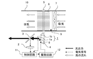
図1は、本発明の実施の形態1によるレーザ光源装置の構成を示す図である。
レーザ光源である半導体レーザ1は、光を発光するチップ1aと該チップ1aの発熱を拡散するステム1bとで構成している。また、半導体レーザ1は、半導体レーザ1からの発熱をさらに拡散するヒートブロック4と熱的に接続している。
ヒートブロック4の熱は、底面部がヒートブロック4と接し、端部に放熱フィン6を有するヒートパイプ5に伝導する。
ヒートパイプ5の端部には放熱フィン6を設けており、ヒートパイプ5の熱は放熱フィン6に伝導し、放熱フィン6に伝導した熱はファン7によって冷気されて排熱される。 なお、放熱フィン6およびファン7は、ダクト10内に設けている。
Hereinafter, an embodiment of the present invention will be described with reference to the drawings.
In the drawings, the same reference numerals indicate the same or equivalent ones.
FIG. 1 is a diagram showing a configuration of a laser light source apparatus according to
A
The heat of the
半導体レーザ1のチップ1aに密着して第1の温度センサ8を配置し、放熱フィン6の吸気側には第2の温度センサ9を配置している。すなわち、第1の温度センサ8は半導体レーザ1のチップ1aの温度を測定できるように配置され、第2の温度センサ9は放熱フィン6の吸気側の温度(すなわち、外気温)を測定できるように配置されている。
半導体レーザ1から出射した光出力の一部は、ビームスプリッタ3によって分離され、フォトダイオード2で受光して、電気信号に変換される。
A
A part of the light output emitted from the
制御回路11は、フォトダイオード2からの電気信号と第1の温度センサ8および第2の温度センサ9の電気信号から、視感度を一定にするようなレーザ光源(すなわち、半導体レーザ1)の駆動電流を算出する。
この算出結果から、駆動回路12を用いて、半導体レーザ1の駆動電流を制御し、光出力変化にともなう半導体レーザ1のチップ1aの温度や半導体レーザ1の周辺温度(例えば、放熱フィン6の吸気側の温度)が変化しても、視感度が一定となるようなAPC(自動出力制御)を行う。
なお、図1において、太い実線の矢印は光出力を、破線の矢印は電気信号を、白抜きの矢印は風の流れを、示している。
The
From this calculation result, the drive current of the
In FIG. 1, thick solid arrows indicate light output, broken arrows indicate electrical signals, and white arrows indicate wind flow.
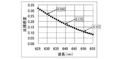
図2は、赤色の光の波長である625nm〜655nmにおける人間の目の感度の波長特性(すなわち、比視感度特性)を示す図である。
なお、比視感度とは、人間の目が光の波長ごとの明るさを感じる強さを数値で表したものであり、人間の目が最大感度となる波長(555nm)における感じる強さを“1”として
、他の波長の明るさを感じる度合いをその比となるように、“1”以下の数で表したものである。
図2に示すように、波長640nmの比視感度は0.175であるが、波長630nmの比視感度は0.266であり、波長640nmの比視感度の約1.5倍である。また波長650nmの比視感度は0.107であり、波長640nmの比視感度の約0.6倍である。
FIG. 2 is a diagram showing the wavelength characteristics of sensitivity of the human eye (that is, specific luminous sensitivity characteristics) at 625 nm to 655 nm, which is the wavelength of red light.
Specific visual sensitivity is the numerical value of the intensity with which the human eye feels the brightness of each wavelength of light. The intensity at which the human eye feels the maximum sensitivity (555 nm) As 1 ”, the degree of feeling the brightness of other wavelengths is represented by a number of“ 1 ”or less so as to be the ratio.
As shown in FIG. 2, the relative visibility at a wavelength of 640 nm is 0.175, but the relative visibility at a wavelength of 630 nm is 0.266, which is about 1.5 times the relative visibility at a wavelength of 640 nm. The relative luminous sensitivity at a wavelength of 650 nm is 0.107, which is approximately 0.6 times the relative luminous sensitivity at a wavelength of 640 nm.
従って、半導体レーザ1の発振波長が640nmから650nmに変化すると、半導体レーザ1の光出力を一定にしていても、人間の目で観測される明るさは、1.5倍になる。
また、発振波長が640nmから630nmに変化すると、人間の目で観測される明るさは、0.6倍になる。
従って、発振波長の変化に対する視感度を補正することは、レーザ光源を用いた画像表示装置において非常に重要である。
なお、実施の形態1では、半導体レーザ1から出射する光が赤色である場合について説明するが、青色や緑色の半導体レーザであっても、図1と同様の構成のレーザ光源装置によって視感度補正を行うことが可能である。
Therefore, when the oscillation wavelength of the
When the oscillation wavelength is changed from 640 nm to 630 nm, the brightness observed with the human eye becomes 0.6 times.
Therefore, it is very important to correct the visibility with respect to the change of the oscillation wavelength in an image display device using a laser light source.
In the first embodiment, the case where the light emitted from the
図3は、図1に示したレーザ光源装置のAPCを示すフローチャートである。
実施の形態1では、第1の温度センサ8および第2の温度センサ9の出力から、レーザ光源(半導体レーザ1)の発振波長λを算出し、視感度が一定になるようにレーザ光源の駆動電流を制御している。
最初に、基準となるレーザ光源の光出力(例えば、出荷時の光出力)Iiniと発振波長(例えば、出荷時の発振波長)λiniを設定(ステップS1)する。通常は画像表示装置の表示映像が標準的な明るさになるように、レーザ光源の光出力Iiniを設定する。
FIG. 3 is a flowchart showing APC of the laser light source device shown in FIG.
In the first embodiment, the oscillation wavelength λ of the laser light source (semiconductor laser 1) is calculated from the outputs of the
First, an optical output (for example, optical output at the time of shipment) I ini and an oscillation wavelength (for example, an oscillation wavelength at the time of shipment) λ ini as a reference are set (step S1). Usually, the light output I ini of the laser light source is set so that the display image of the image display device has a standard brightness.
次に、画像を表示するために、レーザ光源(半導体レーザ1)をON(ステップS2)して駆動を開始する。
その後、第1の温度センサ8および第2の温度センサ9が計測する温度をチェック(ステップS3)し、レーザ光源の発振波長λを算出(ステップS4)する。
この算出した発振波長λの比視感度と、出荷時の発振波長λiniの比視感度を比較して、人の目で感じる明るさが同じになるように、目標光出力Iを算出(ステップS5)する。
第1の温度センサ8および第2の温度センサ9が計測する温度のチェック(ステップS3)とほぼ同時に、フォトダイオード2の受光量IPDをチェック(ステップS6)する。
Next, in order to display an image, the laser light source (semiconductor laser 1) is turned on (step S2) and driving is started.
Thereafter, the temperatures measured by the
The target light output I is calculated so that the brightness perceived by the human eye is the same by comparing the relative luminous sensitivity of the calculated oscillation wavelength λ and the specific luminous sensitivity of the oscillation wavelength λ ini at the time of shipment (step S5).
Checking the temperature which the
発振波長λを考慮した目標光出力Iとフォトダイオード2の受光量IPDの大きさを比較
した結果、 I<IPDの時(ステップS7)、レーザ光源の駆動電流を上げて(ステップS
10)、I=IPDになるようにする。
I>IPDの時(ステップS8)、レーザ光源の駆動電流を下げて(ステップS11)、I
=IPDになるようにする。I=IPDの時(ステップS9)、レーザ光源の駆動電流を維持し
たまま、再度温度センサのチェック(ステップS3)に戻る。
図3に示したステップS3からステップS8は、図1に示した制御回路11で演算を実行する。
ステップS10、ステップS11は、図1に示した駆動回路12で実行する。
As a result of comparing the target light output I in consideration of the oscillation wavelength λ and the received light amount I PD of the
10) I = I PD .
When I> I PD (step S8), the drive current of the laser light source is decreased (step S11).
= I PD . When I = IPD (step S9), the process returns to the temperature sensor check (step S3) again while maintaining the laser light source drive current.
Steps S3 to S8 shown in FIG. 3 are executed by the
Steps S10 and S11 are executed by the
図3のステップS5に記載した「発振波長λを考慮した目標光出力I」と「基準となるレーザ光源の光出力Iini」の関係は、式1のように表すことができる。
I=α×Iini ・・・ (式1)
ここで、αは比例定数であり、発振波長λの関数となる。
例えば、基準となるレーザ光源の光出力Iiniを求めた際の発振波長を640nmとする。
半導体レーザは、光出力変化による温度変化や周辺温度の変化によって、発光効率や発振波長が変化する。
人間の目は視感度を持つため、発振波長λが変化すると、光出力Iが同じでも、人の目で感じる明るさが異なる。
従って、発振波長λが変化すると、発振波長λiniが640nmの時に設定した目標光出力Iiniに対して、人の目で感じる明るさが同じになるように、レーザ光源の光出力Iを変化する必要がある。
式1に記載したαは、この時の補正係数であり、発振波長の関数となる。
The relationship between the “target light output I considering the oscillation wavelength λ” and “the light output I ini of the reference laser light source” described in step S5 in FIG.
I = α × I ini (Formula 1)
Here, α is a proportionality constant and is a function of the oscillation wavelength λ.
For example, the oscillation wavelength when the optical output I ini of the reference laser light source is obtained is 640 nm.
In a semiconductor laser, the light emission efficiency and the oscillation wavelength change due to a change in temperature due to a change in light output and a change in ambient temperature.
Since the human eye has visibility, when the oscillation wavelength λ changes, even if the light output I is the same, the brightness perceived by the human eye is different.
Therefore, when the oscillation wavelength λ changes, the light output I of the laser light source changes so that the brightness perceived by human eyes is the same as the target light output I ini set when the oscillation wavelength λ ini is 640 nm. There is a need to.
Α described in
次に、αを求める。
図2に示した比視感度特性を、640nm付近が“1”になるように規格化すると、図4に
示すグラフになる。
図4は、発振波長640nmが、650nmに変化すると、人間の目の感度が約1.5倍になり、発振波長が630nmに変化すると、人間の目の感度が約0.6倍になることを示している。
Next, α is obtained.
When the relative visibility characteristic shown in FIG. 2 is normalized so that the vicinity of 640 nm is “1”, the graph shown in FIG. 4 is obtained.
FIG. 4 shows that when the oscillation wavelength is changed from 640 nm to 650 nm, the sensitivity of the human eye is about 1.5 times, and when the oscillation wavelength is changed to 630 nm, the sensitivity of the human eye is about 0.6 times. .
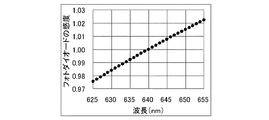
また、フォトダイオード2も、人間の目と同様に波長特性を持っている。
図5にフォトダイオードの波長特性の例を示す。図5は波長640nmの視感度が“1”になるように規格化している。
図4と図5を掛け合わせて、逆数にしたものを図6に示す。
図6は、式1に示した比例定数αのグラフである。
図6のαを2次近似すると、以下の式2のように表すことができる。
α= 0.0015×λ^2 - 1.8162×λ + 566.69 ・・・(式2)
式2より、発振波長λがわかると、αを算出することができる。
この結果、発振波長λを考慮した目標光出力Iが算出(ステップS5)できる。
The
FIG. 5 shows an example of wavelength characteristics of the photodiode. FIG. 5 is normalized so that the visibility at a wavelength of 640 nm is “1”.
FIG. 6 shows the result of multiplying FIG. 4 and FIG.
FIG. 6 is a graph of the proportionality constant α shown in
When α in FIG. 6 is second-order approximated, it can be expressed as the following
α = 0.0015 × λ ^ 2-1.8162 × λ + 566.69 (Equation 2)
From
As a result, the target light output I in consideration of the oscillation wavelength λ can be calculated (step S5).
次に、図3に示した温度センサチェック(ステップS3)および発振波長λの算出(ステップS4)の詳細を記載する。
図7は、図1に示したレーザ光源装置の構成図の熱回路を示す図である。
図7において、QRはチップ1aの発熱量、Tjはチップ1aの温度、Tthは第1の温度センサ8の計測値、Tbはヒートブロック4の温度、Taは第2の温度センサ9の計測値、Rj-thはチップ1a−第1の温度センサ8間の熱抵抗、Rth-bは第1の温度センサ8−ヒー
トブロック4間の熱抵抗、Rb-aはヒートブロック4−第2の温度センサ9間の熱抵抗、Rth-aは第1の温度センサ8−第2の温度センサ9間の熱抵抗である。
Next, details of the temperature sensor check (step S3) and the calculation of the oscillation wavelength λ (step S4) shown in FIG. 3 will be described.
FIG. 7 is a diagram showing a thermal circuit of the block diagram of the laser light source device shown in FIG.
In FIG. 7, Q R is the calorific value of the
図7より、チップ1aの発熱量QRは、式3のように表すことができる。
QR=(Tth-Ta)/Rth-a ・・・ (式3)
また、チップの温度Tjは、式4のように表すことができる。
Tj=Ta+QR×(Rj-th+Rth-a) ・・・ (式4)
式3を式4に代入すると、チップの温度Tjは、式5のように表される。
Tj=Ta+[(Rj-th+Rth-a)/Rth-a]×(Tth-Ta) ・・・ (式5)
From FIG. 7, the calorific value Q R of the
Q R = (T th -T a ) / R th-a (Formula 3)
Further, the chip temperature T j can be expressed as shown in
T j = T a + Q R × (R j−th + R th−a ) (Formula 4)
Substituting
T j = T a + [(R j−th + R th−a ) / R th−a ] × (T th −T a ) (Formula 5)
チップ1aの温度Tjは、発振波長λと比例することが知られている。
λ=A×Tj+B ・・・ (式6)
但し、A、Bは定数
式6に式5を代入すると、発振波長λは、式7のように表すことができる。
λ=A'×Ta+ A''×Tth + B ・・・ (式7)
但し、A'={1-×[(Rj-th+Rth-a)/Rth-a]}×A
A''=[(Rj-th+Rth-a)/Rth-a]×A
式7より、定数であるA'、A''をあらかじめ計測しておけば、第1の温度センサ8の計測値Tthおよび、第2の温度センサ9の計測値Taを用いて、発振波長λを算出することができる。
It is known that the temperature T j of the chip 1a is proportional to the oscillation wavelength λ.
λ = A × T j + B (Formula 6)
However, A and B are constants. When
λ = A ′ × T a + A ″ × T th + B (Formula 7)
However, A ′ = {1- × [(R j-th + R th-a ) / R th-a ]} × A
A '' = [(R j-th + R th-a ) / R th-a ] × A
From
図8に、赤色の半導体レーザ1を用いて、第2の温度センサ9の計測値Taが10℃、18℃、30℃の時に、レーザ光源を光出力変化させた時の、第1の温度センサ8の計測値Tthと、その時の発振波長λを計測した結果を示す。
図8の計測結果から、式7の定数A'、A''、Bは式8のようになる。
半導体レーザの特性から、式7に記載するA''、A’は、A'':0.2〜0.5、A':-0.4〜0の間の値であることを実験的に見出した。
λ=0.34×Tth-0.15×Ta+631.17 ・・・ (式8)
FIG. 8 shows the first temperature when the light output of the laser light source is changed when the measured value Ta of the
From the measurement result of FIG. 8, constants A ′, A ″, and B in
From the characteristics of the semiconductor laser, it was experimentally found that A ″ and A ′ described in
λ = 0.34 × T th -0.15 × T a +631.17 (Equation 8)
これらの結果から、図3に示したAPCの制御フローを、ある一定周期ごとに行うことによって、光出力変化にともなう温度変化や周辺温度が変化しても、視感度が一定となるようなAPCを実現することが可能になる。
この方法は、特許文献1に記載されていた波長フィルタを用いていないので、低コストで簡易に実現可能である。
実施の形態1では、第1の温度センサ8は半導体レーザ1のチップ1a内またはチップ1aと密着させて配置しており、第2の温度センサ9はダクト10内の放熱フィン6の吸気側(すなわち、放熱フィン6とファン7の間)に配置した。
なお、第1の温度センサ8と第2の温度センサ9は、チップ1aおよび放熱フィン6の吸気側間であれば、任意の2箇所に配置しても同様の効果を得ることができる。
本実施の形態では、発熱源であり温度が最も高くなる半導体レーザ1と温度が最も低くなる放熱フィン6の吸気側の2箇所に、第1の温度センサ8と第2の温度センサ9をそれぞれ配置し、第1の温度センサ8と第2の温度センサ9の計測結果の差が大きくなるようにしていることにより、温度センサの測定誤差の影響を小さくできる。
From these results, the APC control flow shown in FIG. 3 is performed every certain period, so that the APC can keep the visibility constant even if the temperature change or the ambient temperature changes due to the light output change. Can be realized.
Since this method does not use the wavelength filter described in
In the first embodiment, the
It should be noted that the
In the present embodiment, the
以上説明したように、実施の形態1によるレーザ光源装置は、レーザ光源である半導体レーザ1と、半導体レーザ1に熱的に接続され、半導体レーザ1からの熱を拡散するヒートブロック4と、一端部がヒートブロック4に接され、他端部に放熱フィン6が設けられたヒートパイプ5と、放熱フィン6を冷却するファン7を備えたレーザ光源装置において、レーザ光源装置内の2箇所の温度を測定するために配置された第1の温度センサ8および第2の温度センサ9と、第1の温度センサ8の出力および第2の温度センサ9の出力から視感度を補正するための制御信号を出力する制御回路11と、制御回路11の出力に基づいて半導体レーザ1を駆動する駆動回路12を備えている。
この構成により、2箇所の温度センサの出力から発振波長を推定することができるため、製作が難しく高価な波長フィルタを用いることなく、低コストで視感度補正が実現可能である。
As described above, the laser light source device according to the first embodiment includes the
With this configuration, since the oscillation wavelength can be estimated from the outputs of the two temperature sensors, visibility correction can be realized at low cost without using an expensive wavelength filter that is difficult to manufacture.
また、実施の形態1によるレーザ光源装置の第1の温度センサ8は半導体レーザ1の温度を計測できる位置に配置され、第2の温度センサ9は放熱フィン6のファン7側(外気温を測定できる位置)に配置されている。
この構成により、2箇所の温度センサ(すなわち、第1の温度センサ8および第2の温度センサ9)の温度差が最も大きくなる。従って、温度センサの測定精度の影響を最大に抑えることができ、視感度補正の精度が向上する。
The
With this configuration, the temperature difference between the two temperature sensors (that is, the
また、実施の形態1によるレーザ光源装置は、第1の温度センサ8の計測値(Tth)およ
び第2の温度センサ9の計測値(Ta)を用いて、線形方程式(λ=A”×Tth+×Ta+B)か
ら発振波長λを推定して視感度を補正する。
この構成により、2箇所の温度センサ(すなわち、第1の温度センサ8および第2の温度センサ9)の出力から発振波長を推定する。そのため、波長フィルタを用いることなく、低コストで視感度を補正することができる。
Further, the laser light source device according to the first embodiment, by using the measurement value (T th) and the measurement value of the
With this configuration, the oscillation wavelength is estimated from the outputs of the two temperature sensors (that is, the
実施の形態2.
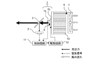
図9は、本発明の実施の形態2によるレーザ光源装置の構成図である。
半導体レーザ1は、光を発光するチップ1aと、チップ1aからの発熱を拡散するステム1bから構成している。
半導体レーザ1は、半導体レーザ1からの発熱を拡散するヒートシンク13と熱的に接続し、ヒートシンク13を冷却するファン7を用いて冷却する。半導体レーザ1とヒートシンク13には、それぞれ第1の温度センサ8と第2の温度センサ9を配置している。
FIG. 9 is a configuration diagram of a laser light source apparatus according to
The
The
実施の形態2においても、第1の温度センサ8と第2の温度センサ9が計測する温度から半導体レーザ1の発振波長λを算出し、視感度が一定になるようにAPCを行う手順は、先の実施の形態1で説明した手順と同様である。
なお、図9においては、実施の形態1によるレーザ光源装置の構成を示す図1の各構成要素と同じ機能を達成する構成要素に関しては、同一符号を付して示している。
この実施の形態2においても、図3に示したAPCの制御フローを、ある一定周期ごとに行うことにより、周辺温度が変化しても、視感度が一定となるようなAPCを実現することが可能になる。
Also in the second embodiment, the procedure for calculating the oscillation wavelength λ of the
In FIG. 9, components that achieve the same functions as the components of FIG. 1 showing the configuration of the laser light source device according to the first embodiment are denoted by the same reference numerals.
Also in the second embodiment, by performing the control flow of APC shown in FIG. 3 at a certain period, it is possible to realize APC in which the visibility is constant even when the ambient temperature changes. It becomes possible.
実施の形態1と同様に、本実施の形態でも、特許文献1に記載されているような製作が難しく高価な波長フィルタを用いていないので、低コストで実現可能である。
また、実施の形態2では、ヒートパイプ5を介さずに半導体レーザ1がヒートシンク13に取り付けられているので装置がコンパクトになる。
Similarly to the first embodiment, this embodiment can be realized at low cost because it does not use an expensive wavelength filter which is difficult to manufacture as described in
In the second embodiment, since the
前述した実施の形態1あるいは実施の形態2では、半導体レーザ1が赤色である場合について説明したが、青色や緑色の半導体レーザであっても、図1あるいは図9と同様の構成のレーザ光源装置で、視感度補正を実現することが可能である。
In the first embodiment or the second embodiment described above, the case where the
以上説明したように、実施の形態2によるレーザ光源装置は、レーザ光源である半導体レーザ1と、半導体レーザ1に熱的に接続されたヒートシンク13と、ヒートシンク13を冷却するファン7を備えたレーザ光源装置において、
レーザ光源装置内の2箇所の温度を測定するため配置された第1の温度センサ8および第2の温度センサ9と、第1の温度センサ8の出力および第2の温度センサ9の出力から視感度を補正するための制御信号を出力する制御回路11と、制御回路11の出力に基づいて半導体レーザ1を駆動する駆動回路12を備えている。
この構成によれば、波長フィルタを用いることなく2箇所の温度センサの出力から発振波長を推定することができるともに、ヒートパイプや放熱フィンを設ける必要がないので、レーザ光源装置をコンパクトにすることができる。
As described above, the laser light source device according to the second embodiment includes the
Viewed from the
According to this configuration, the oscillation wavelength can be estimated from the outputs of the two temperature sensors without using a wavelength filter, and it is not necessary to provide a heat pipe or a heat radiating fin. Can do.
また、実施の形態2においても、第1の温度センサ8は半導体レーザ1の温度を計測する位置に配置され、第2の温度センサ9は放熱フィン6のファン7側に配置されている。
従って、製作が難しく高価な波長フィルタを用いることなく2箇所の温度センサの出力から発振波長を推定することができるともに、ヒートパイプや放熱フィンを設ける必要がないので、レーザ光源装置をコンパクトにすることができる。
さらに、2箇所の温度センサ(すなわち、第1の温度センサ8および第2の温度センサ9)の温度差が最も大きくなるので、温度センサの測定精度の影響を抑えることができ、視感度補正の精度が向上する。
Also in the second embodiment, the
Therefore, it is possible to estimate the oscillation wavelength from the outputs of the two temperature sensors without using an expensive wavelength filter which is difficult to manufacture, and it is not necessary to provide a heat pipe or a heat radiating fin, so that the laser light source device is made compact. be able to.
Furthermore, since the temperature difference between the two temperature sensors (that is, the
実施の形態3.
実施の形態1あるいは実施の形態2によるレーザ光源装置は、R(赤色)、G(緑色)、B(青色)の複数のレーザ光を出射する画像表示装置のレーザ光源として用いることができる。
例えば、特許文献1(国際公開公報WO2010/100898)には、レーザ光源装置と、レーザ光源装置から出射されたレーザ光を空間変調してスクリーンに投写する手段とを有した画像表示装置であって、レーザ光源装置が複数備えられ、複数のレーザ光源装置のそれぞれは、各原色(すなわち、R、G、B)のレーザ光を出射し、複数のレーザ光源装置からの複数のレーザ光を合成する合成手段をさらに有し、空間変調されるレーザ光は、この合成手段によって合成されたレーザ光であることを特徴とする画像表示装置が記載されている。
The laser light source device according to the first embodiment or the second embodiment can be used as a laser light source of an image display device that emits a plurality of laser beams of R (red), G (green), and B (blue).
For example, Patent Document 1 (International Publication No. WO2010 / 100898) is an image display device having a laser light source device and means for spatially modulating laser light emitted from the laser light source device and projecting it onto a screen. A plurality of laser light source devices are provided, and each of the plurality of laser light source devices emits laser light of each primary color (that is, R, G, B), and synthesizes the plurality of laser light from the plurality of laser light source devices. An image display device is further described which further includes a combining unit, and the spatially modulated laser beam is a laser beam combined by the combining unit.
実施の形態3による画像表示装置は、特許文献1に記載されているような波長フィルタを用いたレーザ光源装置に代えて、実施の形態1あるいは実施の形態2によるレーザ光源装置を、各原色(R、G、B)のレーザ光を出射するレーザ光源装置として用いることを特徴とする。
具体的に述べれば、実施の形態3による画像表示装置は、波長フィルタを用いていない実施の形態1あるいは実施の形態2によるレーザ光源装置と、レーザ光源装置から出射されたレーザ光を空間変調してスクリーンに投写する投写手段とを有した画像表示装置であって、レーザ光源装置が3つ配置され、該3つのレーザ光源装置のそれぞれは、各原色のレーザ光を出射し、3つのレーザ光源装置からの3つのレーザ光を合成する合成手段をさらに有し、空間変調されるレーザ光は、合成手段によって合成されたレーザ光であることを特徴とする。 従って、本実施の形態による画像表示装置は、レーザ光源装置は製作が難しく高価な波長フィルタを用いていないので、画像表示装置のコストを低減できる。
The image display device according to the third embodiment replaces the laser light source device according to the first or second embodiment with each primary color (instead of the laser light source device using the wavelength filter as described in Patent Document 1). It is used as a laser light source device for emitting R, G, B) laser light.
Specifically, the image display device according to the third embodiment spatially modulates the laser light source device according to the first or second embodiment that does not use the wavelength filter, and the laser light emitted from the laser light source device. And three laser light source devices, each of which emits a laser beam of each primary color and three laser light sources. The apparatus further includes a combining unit that combines the three laser beams from the apparatus, and the spatially modulated laser beam is a laser beam combined by the combining unit. Therefore, in the image display device according to the present embodiment, the laser light source device is difficult to manufacture and an expensive wavelength filter is not used, so that the cost of the image display device can be reduced.
本発明は、製作が難しい波長フィルタを用いることなく視感度補正機能を備えたレーザ光源装置の実現に有用である。 The present invention is useful for realizing a laser light source device having a visibility correction function without using a wavelength filter that is difficult to manufacture.
1 半導体レーザ 1a チップ 1b ステム
2 フォトダイオード 3 ビームスプリッタ 4 ヒートブロック
5 ヒートパイプ 6 放熱フィン 7 ファン
8 第1の温度センサ 9 第2の温度センサ 10 ダクト
11 制御回路 12 駆動回路 13 ヒートシンク
DESCRIPTION OF
Claims (6)
前記レーザ光源装置内の2箇所の温度を測定するために配置された第1の温度センサおよび第2の温度センサと、
前記第1の温度センサの出力および前記第2の温度センサの出力から視感度を補正するための制御信号を出力する制御回路と、
前記制御回路の出力に基づいて前記半導体レーザを駆動する駆動回路を備えたこと特徴とするレーザ光源装置。 A semiconductor laser that is a laser light source; a heat block that is thermally connected to the semiconductor laser and diffuses heat from the semiconductor laser; one end is in contact with the heat block, and a heat dissipation fin is provided at the other end In the laser light source device provided with a heat pipe and a fan for cooling the radiation fin,
A first temperature sensor and a second temperature sensor arranged to measure two temperatures in the laser light source device;
A control circuit for outputting a control signal for correcting visibility from the output of the first temperature sensor and the output of the second temperature sensor;
A laser light source device comprising a drive circuit for driving the semiconductor laser based on an output of the control circuit.
て、線形方程式(λ=A”×Tth+A’×Ta+B)から発振波長λを推定して視感度を補正することを特徴とする請求項1に記載のレーザ光源装置。 Using the measured value (T th ) of the first temperature sensor and the measured value (T a ) of the second temperature sensor, oscillation from a linear equation (λ = A ″ × T th + A ′ × T a + B) The laser light source device according to claim 1, wherein the visibility is corrected by estimating the wavelength λ.
前記レーザ光源装置内の2箇所の温度を測定するため配置された第1の温度センサおよび第2の温度センサと、
前記第1の温度センサの出力および前記第2の温度センサの出力から視感度を補正するための制御信号を出力する制御回路と、
前記制御回路の出力に基づいて前記半導体レーザを駆動する駆動回路を備えたこと特徴とするレーザ光源装置。 In a laser light source device comprising a semiconductor laser that is a laser light source, a heat sink thermally connected to the semiconductor laser, and a fan that cools the heat sink,
A first temperature sensor and a second temperature sensor arranged to measure two temperatures in the laser light source device;
A control circuit for outputting a control signal for correcting visibility from the output of the first temperature sensor and the output of the second temperature sensor;
A laser light source device comprising a drive circuit for driving the semiconductor laser based on an output of the control circuit.
前記レーザ光源装置が3つ配置され、該3つのレーザ光源装置のそれぞれは、各原色のレーザ光を出射し、前記3つのレーザ光源装置からの3つのレーザ光を合成する合成手段をさらに有し、前記空間変調されるレーザ光は、前記合成手段によって合成されたレーザ光であることを特徴とする画像表示装置。 An image display device comprising: the laser light source device according to any one of claims 1 to 5; and a projection unit that spatially modulates the laser light emitted from the laser light source device and projects the light onto a screen. ,
Three of the laser light source devices are arranged, and each of the three laser light source devices further includes a combining unit that emits laser light of each primary color and combines the three laser light from the three laser light source devices. The image display device characterized in that the spatially modulated laser beam is a laser beam synthesized by the synthesizing means.
Priority Applications (1)
| Application Number | Priority Date | Filing Date | Title |
|---|---|---|---|
| JP2012031251A JP2013168529A (en) | 2012-02-16 | 2012-02-16 | Laser light source device and image display device |
Applications Claiming Priority (1)
| Application Number | Priority Date | Filing Date | Title |
|---|---|---|---|
| JP2012031251A JP2013168529A (en) | 2012-02-16 | 2012-02-16 | Laser light source device and image display device |
Publications (2)
| Publication Number | Publication Date |
|---|---|
| JP2013168529A true JP2013168529A (en) | 2013-08-29 |
| JP2013168529A5 JP2013168529A5 (en) | 2014-01-09 |
Family
ID=49178716
Family Applications (1)
| Application Number | Title | Priority Date | Filing Date |
|---|---|---|---|
| JP2012031251A Pending JP2013168529A (en) | 2012-02-16 | 2012-02-16 | Laser light source device and image display device |
Country Status (1)
| Country | Link |
|---|---|
| JP (1) | JP2013168529A (en) |
Cited By (6)
| Publication number | Priority date | Publication date | Assignee | Title |
|---|---|---|---|---|
| KR101397449B1 (en) | 2013-12-20 | 2014-06-27 | 국방과학연구소 | Heat dissipation apparatus for laser and laser device having the same |
| WO2015045843A1 (en) * | 2013-09-30 | 2015-04-02 | ウシオ電機株式会社 | Laser beam source device |
| WO2016047464A1 (en) * | 2014-09-25 | 2016-03-31 | ソニー株式会社 | Illuminating device, light source control method, and projection type display device |
| JP2017183690A (en) * | 2016-03-28 | 2017-10-05 | 株式会社リコー | Wavelength estimation device, light source device, image display device, object device, wavelength estimation method, and light source control method |
| JP2018041849A (en) * | 2016-09-08 | 2018-03-15 | 株式会社リコー | Light source device, image display unit and object device |
| JP2018122742A (en) * | 2017-02-01 | 2018-08-09 | 株式会社小糸製作所 | Light source drive device, and vehicular lighting tool |
Citations (5)
| Publication number | Priority date | Publication date | Assignee | Title |
|---|---|---|---|---|
| WO2004102754A1 (en) * | 2003-05-13 | 2004-11-25 | Nippon Telegraph And Telephone Corporation | Optical module and its wavelength monitor control method |
| JP2007156438A (en) * | 2005-11-11 | 2007-06-21 | Matsushita Electric Ind Co Ltd | Display device |
| JP2008288352A (en) * | 2007-05-17 | 2008-11-27 | Nippon Telegr & Teleph Corp <Ntt> | Semiconductor laser and semiconductor waveguide element |
| JP2008300661A (en) * | 2007-05-31 | 2008-12-11 | Mitsubishi Electric Corp | Air duct type temperature control device |
| WO2010100898A1 (en) * | 2009-03-04 | 2010-09-10 | 三菱電機株式会社 | Laser light source apparatus and image display apparatus |
-
2012
- 2012-02-16 JP JP2012031251A patent/JP2013168529A/en active Pending
Patent Citations (5)
| Publication number | Priority date | Publication date | Assignee | Title |
|---|---|---|---|---|
| WO2004102754A1 (en) * | 2003-05-13 | 2004-11-25 | Nippon Telegraph And Telephone Corporation | Optical module and its wavelength monitor control method |
| JP2007156438A (en) * | 2005-11-11 | 2007-06-21 | Matsushita Electric Ind Co Ltd | Display device |
| JP2008288352A (en) * | 2007-05-17 | 2008-11-27 | Nippon Telegr & Teleph Corp <Ntt> | Semiconductor laser and semiconductor waveguide element |
| JP2008300661A (en) * | 2007-05-31 | 2008-12-11 | Mitsubishi Electric Corp | Air duct type temperature control device |
| WO2010100898A1 (en) * | 2009-03-04 | 2010-09-10 | 三菱電機株式会社 | Laser light source apparatus and image display apparatus |
Cited By (9)
| Publication number | Priority date | Publication date | Assignee | Title |
|---|---|---|---|---|
| WO2015045843A1 (en) * | 2013-09-30 | 2015-04-02 | ウシオ電機株式会社 | Laser beam source device |
| KR101397449B1 (en) | 2013-12-20 | 2014-06-27 | 국방과학연구소 | Heat dissipation apparatus for laser and laser device having the same |
| WO2016047464A1 (en) * | 2014-09-25 | 2016-03-31 | ソニー株式会社 | Illuminating device, light source control method, and projection type display device |
| JPWO2016047464A1 (en) * | 2014-09-25 | 2017-08-03 | ソニー株式会社 | Illumination device, light source control method, and projection display device |
| US10073331B2 (en) | 2014-09-25 | 2018-09-11 | Sony Corporation | Illumination device and light source control method, and projection display apparatus |
| JP2017183690A (en) * | 2016-03-28 | 2017-10-05 | 株式会社リコー | Wavelength estimation device, light source device, image display device, object device, wavelength estimation method, and light source control method |
| JP2018041849A (en) * | 2016-09-08 | 2018-03-15 | 株式会社リコー | Light source device, image display unit and object device |
| JP7009735B2 (en) | 2016-09-08 | 2022-01-26 | 株式会社リコー | Image display device and object device |
| JP2018122742A (en) * | 2017-02-01 | 2018-08-09 | 株式会社小糸製作所 | Light source drive device, and vehicular lighting tool |
Similar Documents
| Publication | Publication Date | Title |
|---|---|---|
| JP4525767B2 (en) | Lighting device and display device | |
| US9769439B2 (en) | Projector and method for controlling the same the same that adjust light source output based on a corrected detected light brightness | |
| JP2013168529A (en) | Laser light source device and image display device | |
| JP6519970B2 (en) | Image display apparatus, projector and control method thereof | |
| JP5713168B2 (en) | Light source unit and projector | |
| JP6493739B2 (en) | Light source device and projection device | |
| JP6252081B2 (en) | Projector and control method thereof | |
| JP2008193054A (en) | Light source device, projector device, monitor device, and lighting device | |
| JP6286825B2 (en) | Projector and control method thereof | |
| JP2013258357A (en) | Semiconductor light source device | |
| JP4838397B1 (en) | Image display device | |
| JP2014035386A (en) | Image display device and method for controlling light source | |
| JP2005115350A (en) | Temperature measuring device, light source controller, projector, temperature measuring method and light source control method | |
| JP2010169754A (en) | Image display | |
| JP5278090B2 (en) | Video display device | |
| JP2012053279A (en) | Color image forming apparatus, color image forming method, and projector including the color image forming apparatus | |
| JP6171929B2 (en) | Projection device, control method of projection device, and program | |
| JP5841691B2 (en) | Light source device and endoscope device | |
| JP4891453B1 (en) | Image display device | |
| JP2016224115A (en) | Fluorescent light source apparatus, image projector; and fluorescent light source control program | |
| JP6731784B2 (en) | Light source device and image display device | |
| JP2011133535A (en) | Projector, method for setting initial driving voltage of projector light source, and method for setting driving voltage of projector light source | |
| JP7238784B2 (en) | image display device | |
| JP2014187465A (en) | Light source device and projector | |
| JP7204379B2 (en) | Light source device and image projection device |
Legal Events
| Date | Code | Title | Description |
|---|---|---|---|
| A521 | Written amendment |
Free format text: JAPANESE INTERMEDIATE CODE: A523 Effective date: 20131114 |
|
| A621 | Written request for application examination |
Free format text: JAPANESE INTERMEDIATE CODE: A621 Effective date: 20131114 |
|
| A977 | Report on retrieval |
Free format text: JAPANESE INTERMEDIATE CODE: A971007 Effective date: 20140328 |
|
| A131 | Notification of reasons for refusal |
Free format text: JAPANESE INTERMEDIATE CODE: A131 Effective date: 20141118 |
|
| A02 | Decision of refusal |
Free format text: JAPANESE INTERMEDIATE CODE: A02 Effective date: 20150331 |