JP2013166344A - Liquid cleaning filling unit, image forming apparatus, liquid cleaning filling method in image forming apparatus, and liquid cleaning filling kit - Google Patents
Liquid cleaning filling unit, image forming apparatus, liquid cleaning filling method in image forming apparatus, and liquid cleaning filling kit Download PDFInfo
- Publication number
- JP2013166344A JP2013166344A JP2012032019A JP2012032019A JP2013166344A JP 2013166344 A JP2013166344 A JP 2013166344A JP 2012032019 A JP2012032019 A JP 2012032019A JP 2012032019 A JP2012032019 A JP 2012032019A JP 2013166344 A JP2013166344 A JP 2013166344A
- Authority
- JP
- Japan
- Prior art keywords
- liquid
- tank
- cleaning
- ink
- head
- Prior art date
- Legal status (The legal status is an assumption and is not a legal conclusion. Google has not performed a legal analysis and makes no representation as to the accuracy of the status listed.)
- Granted
Links
Images


Landscapes
- Ink Jet (AREA)
Abstract
【課題】洗浄に多量の液体が必要であり、入れ替え時間もかかり、ノズルへの気泡混入による不吐出が発生する。
【解決手段】インク洗浄充填ユニット61は、充填するインク中の溶存気体を取り除いたインクを封入し密閉したインクボトル63と、このインクをヘッドユニット1へ圧送(加圧送液)するための空気や窒素などの気体を封じた加圧用ボンベ62とを有し、ヘッド1及びタンク4内の液体を入れ替えるときに、タンク4内へ圧縮気体を供給し、タンク4内の液体を排出させ、タンク4内の液体が全て排出していない状態で、インクボトル63の液体を供給し、供給した液体でタンク4を満たす、ことを繰り返しながら、ヘッド1及びタンク4内の洗浄を行って液体を入替え充填する。
【選択図】図3A large amount of liquid is required for cleaning, and it takes a long time to replace the liquid.
An ink cleaning and filling unit 61 includes an ink bottle 63 in which an ink from which dissolved gas in the ink to be filled is removed is sealed and air for pressure-feeding (pressure feeding) the ink to a head unit 1 And a pressurizing cylinder 62 sealed with a gas such as nitrogen. When the liquid in the head 1 and the tank 4 is replaced, a compressed gas is supplied into the tank 4 to discharge the liquid in the tank 4. While the liquid in the ink bottle 63 is not completely discharged, the liquid in the ink bottle 63 is supplied and the tank 4 is filled with the supplied liquid. To do.
[Selection] Figure 3
Description
本発明は液滴を吐出して画像を形成する画像形成装置、同画像形成装置の液体吐出ヘッドに液体を充填する液体洗浄充填ユニット、画像形成装置、画像形成装置における液体洗浄充填方法、液体洗浄充填キットに関する。 The present invention relates to an image forming apparatus that discharges droplets to form an image, a liquid cleaning and filling unit that fills a liquid discharge head of the image forming apparatus with liquid, an image forming apparatus, a liquid cleaning and filling method in the image forming apparatus, and liquid cleaning It relates to a filling kit.
プリンタ、ファクシミリ、複写装置、プロッタ、これらの複合機等の画像形成装置として、例えばインク液滴を吐出する液体吐出ヘッド(液滴吐出ヘッド)からなる記録ヘッドを用いた液体吐出記録方式の画像形成装置としてインクジェット記録装置などが知られている。 As an image forming apparatus such as a printer, a facsimile, a copying machine, a plotter, or a complex machine of these, for example, a liquid discharge recording type image forming using a recording head composed of a liquid discharge head (droplet discharge head) that discharges ink droplets. As an apparatus, an ink jet recording apparatus or the like is known.
画像形成装置として用いられるインクジェット記録装置におけるインク供給方式として、記録ヘッド側にヘッドタンク(サブタンク、バッファタンクなども同義とする。)を、装置本体側にメインタンクを配置して、メインタンクからヘッドタンクにインクを補充供給し、ヘッドタンクから記録ヘッドにインクを供給する方式が知られている。 As an ink supply method in an ink jet recording apparatus used as an image forming apparatus, a head tank (sub tank, buffer tank, etc. is also synonymous) is arranged on the recording head side, and a main tank is arranged on the apparatus main body side. A system is known in which ink is replenished and supplied to a tank, and ink is supplied from a head tank to a recording head.
ところで、画像形成装置を、用途により、1台の装置で異なる種類のインクを入替えて使用することがある。例えば、染料インクと顔料インクを入れ替えたり、モノクロインクをカラーインクに入れ替えたりといったように、異なる種類のインクを使用することがある。 By the way, the image forming apparatus may be used by replacing different types of ink in one apparatus depending on the application. For example, different types of ink may be used, such as replacing dye ink and pigment ink, or replacing monochrome ink with color ink.
そのため、それぞれのインクが混合しないように、インクを入れ替えるときには、洗浄液や空気を供給流路内に供給して、ヘッドまでの流路を洗浄した後、入れ替えるインクを流路に供給する方法が知られている(特許文献1)。 Therefore, when replacing the ink so that the respective inks are not mixed, a method is known in which cleaning liquid or air is supplied into the supply flow path, the flow path to the head is washed, and then the replacement ink is supplied to the flow path. (Patent Document 1).
しかしながら、液体による置換洗浄によるインク入替方法では、ヘッドタンク内にある液体の流れによどみが生じ、ヘッドタンク内全てを洗浄するには、多量の液体を流す必要があり、時間も必要であるという課題がある。 However, in the ink replacement method by replacement cleaning with liquid, stagnation is caused by the flow of liquid in the head tank, and it is necessary to flow a large amount of liquid and time is required to clean the entire head tank. There are challenges.
また、気体を圧送する方法では、ノズル部へ気体が混入し、インク入替え後インクを吐出させるときに、この気泡が排出できずに不吐出を発生させるという課題がある。 Further, in the method of pumping gas, there is a problem that when the gas is mixed into the nozzle portion and the ink is ejected after ink replacement, the bubbles cannot be discharged and non-ejection occurs.
本発明は上記の課題に鑑みてなされたものであり、タンク内での液体のよどみの発生を低減して、少量の液体で洗浄可能で、ノズルへの気泡混入を抑えつつ、短時間で液体入れ替え作業を行うことができるようにすることを目的とする。 The present invention has been made in view of the above-described problems, reduces the occurrence of liquid stagnation in the tank, can be washed with a small amount of liquid, and can prevent liquid from entering the nozzle in a short time. The purpose is to enable replacement work.
上記の課題を解決するため、請求項1に係る液体洗浄充填ユニットは、
液滴を吐出するヘッド及び前記ヘッドに供給する液体を収容するタンクを洗浄して前記液体を充填する液体洗浄充填ユニットであって、
充填する前記液体を収容した液体収容手段と、
前記液体収容手段内の液体を加圧して前記液体を前記タンクの液体供給ポートに送液させる加圧手段と、
圧縮気体を前記タンクの液体供給ポートに圧送する手段と、を備え、
前記ヘッド及び前記タンク内の液体を入れ替えるときに、
前記タンク内へ前記圧縮気体を供給し、前記タンク内の液体を排出させ、
前記タンク内の前記液体が全て排出していない状態で、前記液体収容手段の前記液体を供給し、
供給した前記液体で前記タンクを満たす、ことを繰り返しながら、前記ヘッド及び前記タンク内の洗浄を行う
構成とした。
In order to solve the above problem, a liquid cleaning and filling unit according to
A liquid washing and filling unit for washing a head for discharging droplets and a tank for storing a liquid to be supplied to the head to fill the liquid,
Liquid storage means for storing the liquid to be filled;
Pressurizing means for pressurizing the liquid in the liquid storage means and feeding the liquid to the liquid supply port of the tank;
Means for pumping compressed gas to the liquid supply port of the tank,
When replacing the liquid in the head and the tank,
Supplying the compressed gas into the tank, and discharging the liquid in the tank;
In a state where all the liquid in the tank is not discharged, the liquid in the liquid storage means is supplied,
The head and the tank were cleaned while repeating the filling of the tank with the supplied liquid.
本発明によれば、タンク内での液体のよどみの発生を低減して、少量の液体で洗浄可能で、ノズルへの気泡混入を抑えつつ、短時間で液体入れ替え作業を行うことができる。 According to the present invention, it is possible to reduce the occurrence of stagnation of liquid in the tank, wash with a small amount of liquid, and perform a liquid replacement operation in a short time while suppressing the mixing of bubbles into the nozzle.
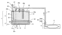
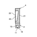
以下、本発明の実施形態について添付図面を参照して説明する。本発明の第1実施形態について図1及び図2を参照して説明する。図1は同実施形態におけるインク供給系の模式的説明図、図2は図1のA−A線に沿うヘッドタンクの断面説明図である。 Embodiments of the present invention will be described below with reference to the accompanying drawings. A first embodiment of the present invention will be described with reference to FIGS. FIG. 1 is a schematic explanatory view of an ink supply system in the embodiment, and FIG. 2 is a cross-sectional explanatory view of a head tank taken along line AA of FIG.
液体吐出ヘッドユニット(以下、単に「ヘッドユニット」ともいう。)1は、液滴を吐出するヘッド2と、ヘッド2に供給するインクを収容するヘッドタンク(以下、単に「タンク」ともいう。)4とを備えている。
A liquid discharge head unit (hereinafter also simply referred to as “head unit”) 1 includes a
ヘッド2は、液滴を吐出する複数のノズル11と、各ノズル11が連通する液室12と、各液室12にインクを供給する共通液室13と、共通液室13にインクを供給される供給口(インク供給ポート)14と、共通液室13からインクを排出する排出口(インク排出ポート)15などを備えている。
The
ヘッドタンク4は、タンクケース21内に、ヘッド2に供給するインクを収容するインク収容部22と、インク収容部22からインクをヘッド2の供給口14に供給する供給ポート24と、ヘッド2の排出口15から排出されるインクを排出流路39に排出する排出経路25と、収容部22と排出経路25を通じる通路26とが設けられている。
The
インク収容部22の天面22aは傾斜面に形成され、このインク収容部22の天面22aの最も高い部位22bと、このインク収容部22の天面22aの最も高い部位22b以上の高さの排出経路25の部位とを通路26で連通している。なお、通路26の流体抵抗は、ヘッド2のインク供給ポート14からインク排出ポート15までの流体抵抗よりも大きく形成されている。
The
また、ヘッドタンク4の上部には、インク収容部22内のインク量が所定量以下になったことを検知するための2対の検知電極29a、29bを装着している。この検知電極29a、29bは、図示しない検知信号を入力する制御部に接続され、液量検知センサを構成している。
In addition, two pairs of
この検知電極29a、29bが何れもインクに浸されている状態と少なくとも一方がインクに浸されていない状態とで検知電極29a、29b間の導通状態が変化することによってインクが所定量以下になったことを検知することができるものである。
When the
検知電極29aは,インク収容部22のインク量が満タン(Hレベル)の状態にあることを検知できるように、インク収容部22の天面22a付近に下端部が位置して設置されている。また、検知電極29bは、インク収容部22のインク量が少ない(Lレベル)状態にあることを検知できるように、インク収容部22の底面22c付近に下端部が位置して設置されている。
The
この液量検知センサを用いることにより、インク収容部22内のインク量がHレベル(検知電極29a,29bが共に導通状態),Lレベル(検知電極29a,29bが共に不通状態),HレベルとLレベルの間である中間レベル(検知電極29aが不通状態で,検知電極29bが導通状態)を検出できる。
By using this liquid amount detection sensor, the amount of ink in the
また、ヘッドタンク4のタンクケース21は、一方が開口した部材であり、開口部には撓むことができる弾性変形可能な部材としてのフィルム部材23を貼り付けて、圧力変動を吸収する構成としている。
Further, the
さらに、ヘッドタンク4の排出経路25の排出側は排出流路39に通じ、この排出流路39の先端部には開閉可能な開閉弁(開閉バルブ)54を設けている。この開閉バルブ54の他端は、後述するインク洗浄充填ユニット61の着脱可能な継手56Bを接続可能(連結可能)な構成としている。
Further, the discharge side of the
一方、装置本体側には、ヘッドタンク4にインクを補充供給する交換可能なメインタンク(インクカートリッジ)5が配置されている。
On the other hand, a replaceable main tank (ink cartridge) 5 is disposed on the apparatus main body side to supply and replenish ink to the
このメインタンク5は、補充供給するインクと、該インクと外部の大気から遮断し、内部を密閉できるアルミなどが蒸着され複数の層からなるインク量に応じて自由に変形可能なインクパック6と、先端部にバルブが付いた着脱可能な継手56を設けており、インク供給経路51から着脱可能になっており、この継手56を取り外すことで容易にメインタンク5の交換ができるようになっている。
The main tank 5 includes ink to be replenished and an ink pack 6 that can be freely deformed in accordance with the amount of ink composed of a plurality of layers deposited with aluminum or the like that can be sealed from the outside of the ink and the outside atmosphere. A
なお、継手56は、インク供給経路51側に連結された部分を継手56Aとし、メインタンク5側に連結された側を継手56Bとする。
In the
このインク供給系においては、ヘッドタンク4に収容されたインクは、供給ポート24を通じてヘッド2の一端部のインク供給ポート14から共通液室13の一端部から供給され、共通液室13に供給され、排出経路25及び排出流路39内に充填される。そして、ヘッド2からの滴吐出に伴ってインクが消費されることにより、ヘッドタンク4からインクがヘッド2に供給され、メインタンク5からヘッドタンク4にインクが自然供給される。
In this ink supply system, the ink stored in the
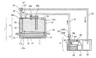
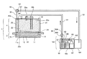
次に、このインク供給系のヘッドユニット1にインクを初期充填する本発明に係る液体洗浄充填ユニットであるインク洗浄充填ユニット及びインク充填キットについて図3を参照して説明する。
Next, an ink washing and filling unit and an ink filling kit, which are liquid washing and filling units according to the present invention for initially filling ink in the
インク洗浄充填ユニット61は、充填するインク中の溶存気体を取り除いたインクを封入し密閉した液体収容手段であるインクボトル63と、このインクをヘッドユニット1へ圧送(加圧送液)するための空気や窒素などの気体を封じた加圧手段である加圧ボンベ62とをユニット化(一体化)して構成している。
The ink cleaning and filling
このインク洗浄充填ユニット61と回収液体収容手段である廃液ボトル64とを併せてインク洗浄充填キットを構成している。なお、ユニット化しないインクボトル63及び加圧ボンベ62と、廃液ボトル64とによってインク洗浄充填ユニット61を構成することもできる。
The ink cleaning and filling
ボンベ62の先端には、開閉可能なタンクバルブ66が設けられている。タンクバルブ66の先は分岐されて、1つは、インクボトル63から供給されるインクと流路が切換え可能な三方切替弁168に連結されている。また、他の1つは、二方切替弁167を介して、インクボトル63に連結されている。
A
また、インクボトル63に通じる供給経路67には、インク供給経路51側の継手56Aと連結可能なメインタンク5と同じ継手56Bが設けられている。
Further, the
さらに、ヘッドタンク4側の開閉弁(バルブ)54に接続可能な継手57を先端部に有するインク戻り経路53を有し、インク戻り経路53はインク充填により排出されるインクを回収する廃液ボトル64が取付けられている。
Furthermore, it has an
ここで、インクボトル63側の継手56Bは通常は閉じている状態で、継手56Aに接続(連結)した時に開くものを用いている。
Here, the joint 56B on the
そして、インクボトル63内のインクは、インク中の溶存気体を取り除いたインクを封入し内部の空気を排除し、継手56Bとタンクバルブ66により密閉されているものを用いている。インクボトル63からインクをヘッドユニット1へ圧送するために、インクボトル63を気体で加圧するときに、タンクバルブ66を開き、ボンベ62から圧縮気体を供給する構成としている。これは、インク充填時に加圧する気体がインク内に溶け込む量をできるだけ少なくするためである。
The ink in the
また、廃液ボトル64は、ヘッドユニット1から排出されるインクを収容するため、その分の容量をもつ廃液ボトルにすることで、廃液ボトル64からインクを溢れさせるおそれを避けることができる。
Further, since the
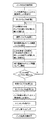
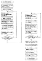
次に、このインク洗浄充填ユニット61及び廃液ボトル64を使用してヘッドユニット1を洗浄してインクを充填する充填方法について図4のフロー図も参照して説明する。
Next, a filling method in which the
まず、図3に示すように、メインタンク5を継手56から外し、インク洗浄充填ユニット61を継手56で取付け、インク供給経路51とインクボトル63とを接続する。さらに、開閉弁(バルブ)54に継手57を介してインク戻り経路53を接続し、ヘッドタンク4の排出流路39と廃液ボトル64とを接続する(取付ける)。
First, as shown in FIG. 3, the main tank 5 is removed from the joint 56, the ink cleaning and filling
次に、タンクバルブ66を開き、三方切替弁168をボンベ62と継手56とが通じる方向へ切り替え、さらに、開閉弁(バルブ)54を開き、加圧気体によりタンク4内のインクを排出流路39から廃液ボトル64へ排出させる。
Next, the
ここで、タンク4内のインク残量が、検知電極29bでLレベルになったことが検知されたら二方切替弁167を開きボンベ62からの加圧気体をインクボトル63内に供給し,三方切替弁168をインクボトル63と継手56が通じる方向へ切換えることで、インクを供給する。
Here, when it is detected that the remaining amount of ink in the
これにより、ヘッドタンク4にインクが供給されるので、検知電極29aでインクが充填された(Hレベルになった)ことを検知したら、再度、三方切替弁168をボンベ62と継手56が通じる方向に切換え、加圧気体を送り込み、ヘッドタンク4内のインクを排出流路39から廃液ボトル64へ排出させる。
As a result, since ink is supplied to the
この動作を繰り返し、ヘッドタンク4内の液体がインクボトル63内の液体に十分入れ替わるまで繰り返し行う。
This operation is repeated until the liquid in the
この場合、加圧気体を供給しないで液体のみの送液を行って入れ替える方法では、ヘッドタンク4内のインクは、流れによどみが生じ、特にインク供給流路と供給ポートから遠いインク収容部22の天面22aのよどみが大きくなることが確認されている。
In this case, in the method of replacing only by supplying liquid without supplying pressurized gas, the ink in the
これに対し、本実施形態のように加圧気体を供給することで、インク収容部22の天面22a部分のインクが加圧気体により排出されため、洗浄用インクが少量で、かつ短時間でインクの洗浄(入れ替え)を行うことができるようになる。
On the other hand, by supplying the pressurized gas as in the present embodiment, the ink on the
そして、ヘッドタンク4内の液体がインクボトル63内のインクに十分入れ替わった後、インクボトル63内のインクでヘッドタンク4内を満たした状態で、開閉バルブ54を閉じる。その間、インクボトル63から送液されるインクでノズル11内のインクを入れ替えることができる。
Then, after the liquid in the
その後、タンクバルブ66を閉じ、インク供給経路51へのインクの加圧送液を止め、継手56、継手57からインク洗浄充填ユニット61を取り外す。
Thereafter, the
そして、継手56からメインタンク5を取り付け、メインタンク5とヘッド2のノズル11との水頭差によって発生するインクの吐出に必要な負圧を作り出す。
Then, the main tank 5 is attached from the joint 56, and a negative pressure necessary for ejecting ink generated by the water head difference between the main tank 5 and the
その後、ここでは、図示しない弾性体、好ましくはシリコンゴム等のワイパ部材によりノズル表面をワイピングし、ノズル面11aに垂れたインクを払拭し、ノズル11のメニスカスを形成させ、インク充填を完了させる。
Thereafter, the nozzle surface is wiped with an elastic body (not shown), preferably a wiper member such as silicon rubber, and the ink dripping on the
このようにして、ヘッド2のインクを洗浄し,入れ替えたインクを充填させ、常にメインタンク5からヘッドタンク4を通じてヘッド2にインクを供給してインク吐出可能な状態とすることができる。
In this way, the ink of the
この洗浄充填の各工程において,ヘッドタンク4内に加圧気体を送り込んだ場合、気体は、通路26から排出流路39へ排出される他は、ヘッドタンク4の上層部へ溜まり、ヘッドタンク4の底面22cまで達しなければ、共通液室13側へは流出しない。このため、ノズル11へ気泡が混入しないようにすることができる。
In each cleaning and filling process, when pressurized gas is fed into the
また、このインク洗浄充填ユニット61は、充填する液体を収容した液体収容手段と、液体収容手段内の液体を加圧して液体をタンクの液体供給ポートに送液させる加圧手段とを備えているので、画像形成装置側に液体供給ポンプを設けないでも液体の初期充填を行なうことができ、画像形成装置の構成を小型化、簡素化できる。
The ink cleaning and filling
また、インク洗浄充填ユニット61は、充填する液体を収容した液体収容手段と、液体収容手段内の液体を加圧して液体をタンクの液体供給ポートに送液させる加圧手段と、タンクの液体排出ポートから排出される液体を回収して収容する回収液体収容手段とを備えているので、画像形成装置側に液体供給ポンプを設けないでも液体の初期充填を行なうことができ、画像形成装置の構成を小型化、簡素化できる。
The ink cleaning and filling
次に、本発明の第2実施形態について図5を参照して説明する。図5は同実施形態のインク洗浄充填時の模式的説明図である。 Next, a second embodiment of the present invention will be described with reference to FIG. FIG. 5 is a schematic explanatory view at the time of ink cleaning filling of the same embodiment.
ここでは、インク洗浄充填ユニット71として、前記第1実施形態におけるインク洗浄充填ユニット61(液体収容手段であるインクボトル63と、加圧手段である加圧ボンベ62とをユニット化したもの)と、回収液体収容手段である廃液ボトル64をも一体化(ユニット化)している。
Here, as the ink cleaning / filling
この実施形態によるインク充填動作は前記第1実施形態と同様である。 The ink filling operation according to this embodiment is the same as that of the first embodiment.
このように、この液体洗浄充填ユニットは、充填する液体を収容した液体収容手段と、液体収容手段内の液体を加圧して液体をタンクの液体供給ポートに送液させる加圧手段と、タンクの液体供給排出ポートから排出される液体を回収して収容する回収液体収容手段とを備えているので、画像形成装置側に液体供給ポンプを設けないでも液体の初期充填を行なうことができ、画像形成装置の構成を小型化、簡素化できる。 As described above, the liquid cleaning and filling unit includes a liquid storage unit that stores a liquid to be filled, a pressurization unit that pressurizes the liquid in the liquid storage unit and sends the liquid to the liquid supply port of the tank, Since the liquid supply means for collecting and storing the liquid discharged from the liquid supply / discharge port is provided, it is possible to perform initial liquid filling without providing a liquid supply pump on the image forming apparatus side, and image formation The device configuration can be reduced in size and simplified.
そして、この液体洗浄充填ユニットを使用して液体の充填を行なうことで、画像形成装置側に液体供給ポンプを設けないでも液体の初期充填を行なうことができ、画像形成装置の構成を小型化、簡素化できる。 Then, by using this liquid cleaning and filling unit to fill the liquid, the liquid can be initially filled without providing a liquid supply pump on the image forming apparatus side, and the configuration of the image forming apparatus can be reduced in size. It can be simplified.
さらに、ユニット化することで、持ち運びなどの取扱いが容易になる。 Furthermore, handling such as carrying around becomes easy by unitizing.
次に、本発明の第3実施形態について図6を参照して説明する。図6は同実施形態の要部模式的説明図である。 Next, a third embodiment of the present invention will be described with reference to FIG. FIG. 6 is a schematic explanatory diagram of a main part of the embodiment.
このインク洗浄充填ユニット81は、充填するインク中に溶け込む溶存気体を取り除いたインクを封入し密閉したインクボトル63と、インク充填により排出されるインクを回収する廃液ボトル64とをユニット化したものである。
The ink cleaning and filling unit 81 is a unitized unit of an
インクボトル63には、コンプレッサーや加圧ポンプなどの加圧機構70よる圧縮気体を用いて、圧力調整手段であるレギュレータ69を介して継手58によりタンクバルブ66に接続する構成としている。
The
レギュレータ69(圧力調整手段)は、インクボトル63内のインクを加圧する圧縮気体の圧力を調整するために設けている。この圧力値は、インク流路の抵抗や、作業環境温度変化によるインク粘度変化など、ヘッドユニット1内に流入するインクの流速を調整し、流路内の気泡を移動させやすくし,インクを確実に充填できるように適切に選ぶことができる。したがって、圧力調整手段は前記第1、第2実施形態に適用することも好ましい。
The regulator 69 (pressure adjusting means) is provided to adjust the pressure of the compressed gas that pressurizes the ink in the
なお、この実施形態によるインク充填動作は前記第1実施形態と同様である。 The ink filling operation according to this embodiment is the same as that of the first embodiment.
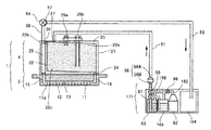
次に、本発明の第4実施形態について図7を参照して説明する。図7は同実施形態のインク洗浄充填時の模式的説明図である。 Next, a fourth embodiment of the present invention will be described with reference to FIG. FIG. 7 is a schematic explanatory view at the time of ink cleaning and filling in the same embodiment.
上記各実施例では、インクから交換インクへの直接入替えの例を説明したが、使用中のインクと交換インクが混ざり合うと、インクの凝集・固化によるノズル詰まりやインクの変色等の印写に不具合が生じてしまう場合がある。このような場合において、使用中のインクを不具合の発生しない洗浄液に入れ替えてから、次に使用するインクに入替えることでインク入替えを実施することが可能となる。 In each of the above embodiments, an example of direct replacement from ink to replacement ink has been described. However, if the ink being used and the replacement ink are mixed, printing such as nozzle clogging or ink discoloration due to ink aggregation / solidification may occur. There may be a problem. In such a case, it is possible to perform ink replacement by replacing the ink that is being used with a cleaning liquid that does not cause a problem and then replacing it with the ink to be used next.
そこで、本実施形態においては、インク洗浄充填ユニット161は、前記第1実施形態におけるインク洗浄充填ユニット61を構成する、インクボトル63及び加圧ボンベ62に加えて、水のほか界面活性剤や保湿剤などを含有させたこのインクよりも粘度が低く、表面張力が低い水溶液を用いた洗浄液を封入した洗浄液収容手段である洗浄液ボトル165をユニット化(一体化)して構成している。
Therefore, in the present embodiment, the ink cleaning and filling unit 161 includes, in addition to the
このインク洗浄充填ユニット161と回収液体収容手段である廃液ボトル164とを併せてインク洗浄充填キットを構成している。なお、ユニット化しないインクボトル63、洗浄液ボトル165、及び加圧ボンベ62と、廃液ボトル164とによってインク洗浄充填キットを構成することもできる。
The ink cleaning and filling unit 161 and the
加圧ボンベ62とインクボトル63及び洗浄液ボトル65との間は気体流路162で通じている。気体流路162には、加圧ボンベ62からの供給側に開閉可能なタンクバルブ66が設けられ,その先は,インクボトル63と洗浄液ボトル165,三方切替弁68へ分岐され,インクボトル63,洗浄液ボトル165から供給される液体の流路が切換可能な三方切替弁168が設けられている。
A
また、インク戻り経路53はインク及び洗浄液による洗浄により排出されるインク及び洗浄液を回収する廃液ボトル164を取付けられている。
The
ここで、前記第1実施形態と同様に、インクボトル63側の継手56Bは通常は閉じている状態で、継手56Aに接続(連結)した時に開くものを用いている。そして、インクボトル63内のインクは、インク中の溶存気体を取り除いたインクを封入し内部の空気を排除し継手56Bとタンクバルブ66により密閉されているものを用いている。
Here, as in the first embodiment, the joint 56B on the
また、三方切替弁68は、継手56Bと洗浄液ボトル165が通じている状態にあり、三方切替弁168とインクボトル63間の液体流路内にはインクが詰まっている状態、もしくは真空の状態である。
The three-
インクボトル63からインクをヘッドユニット1へ圧送するために、インクボトル63を気体で加圧するときに、タンクバルブ66を開き、気体を供給する構成としている。これは、インク充填時に加圧する気体がインク内に溶け込む量をできるだけ少なくするためである。
In order to pressure-feed ink from the
また、廃液ボトル164は、ヘッドユニット1からの排出されるインク及び洗浄液を収容するため、その分の容量をもつ廃液ボトルにすることで、廃液ボトル164からインク及び洗浄液を溢れさせるおそれを避けることができる。
Further, since the
次に、この実施形態においてヘッドユニット1にインク及び洗浄液を充填する洗浄充填方法について図8のフロー図も参照して説明する。
Next, a cleaning and filling method for filling the
まず、図7に示すように、メインタンク5を継手56から外し、インク洗浄充填ユニット161を継手56で取付け、インク供給経路51とインクボトル63及び洗浄液ボトル165とを接続する。さらに、開閉弁(バルブ)54に継手57を介してインク戻り経路53を接続し、ヘッドタンク4の排出流路39と廃液ボトル164とを接続する(取付ける)。
First, as shown in FIG. 7, the main tank 5 is removed from the joint 56, the ink cleaning and filling unit 161 is attached by the joint 56, and the
次に、タンクバルブ66を開き、三方切替弁68をタンクバルブ66と継手56が通じる方向へ切り替え、さらに開閉弁(バルブ)54を開き、ヘッドタンク4に加圧気体を供給して、ヘッドタンク4内のインクを排出流路39から廃液ボトル164へ排出させる。
Next, the
ヘッドタンク4内のインク残量が検知電極29bでLレベルになったことを検知したときには、三方切替弁68,三方切替弁168を洗浄液ボトル165と継手56が連通する方向へ切換え、ヘッドタンク4に洗浄液を供給する。
When it is detected that the ink remaining amount in the
次に、検知電極29aで液体(ここでは、洗浄液)が充填されたこと(Hレベルになったこと)を検知したときに、再度、三方切替弁68を加圧ボンベ62と継手56が連通する方向に切換え、加圧気体によりボンベ62から継手56に加圧気体を送り込み、ヘッドタンク4内のインクないし洗浄液を排出流路39から廃液ボトル164へ排出させる。
Next, when the
この動作を繰り返し、タンク4内の液体(インク)が洗浄液に十分入れ替わるまで繰り返し行う。
This operation is repeated until the liquid (ink) in the
ヘッドタンク4内の液体が十分洗浄液で洗浄され、洗浄液へ入れ替わった後、三方切替弁68をボンベ62と継手56が通じる方向に切換え,加圧気体によりヘッドタンク4内に加圧気体を送り込み、検知電極29bでLレベルになったことが検知されるまでヘッドタンク4内の洗浄液を排出流路39から廃液ボトル164へ排出させる。
After the liquid in the
そして、三方切替弁68をインクボトル63と継手56が通じる方向へ切換え、ヘッドタンク4内への気体供給を止め,その後、三方切替弁168をインクボトル63と継手56が通じる方向へ切換え,インクをヘッドユニット1へ送液する。
Then, the three-
ヘッドタンク4内の液体がインクボトル63内のインクに十分入れ替わった後、インクボトル63内のインクでヘッドタンク4内を満たした状態で、開閉バルブ54を閉じる。
After the liquid in the
これにより,インクボトル63から送液されるインクでノズル11内のインクを入れ替えることができる。
Thereby, the ink in the
その後、タンクバルブ66を閉じ、インク供給経路51へのインク圧送を止め、継手56、継手57からインク洗浄充填ユニット161を取り外す。
Thereafter, the
そして、継手56からメインタンク5を取り付け、メインタンク5とヘッド2のノズル11との水頭差によって発生するインクの吐出に必要な負圧を作り出す。
Then, the main tank 5 is attached from the joint 56, and a negative pressure necessary for ejecting ink generated by the water head difference between the main tank 5 and the
その後、ここでは、図示しない弾性体、好ましくはシリコンゴム等のワイパ部材によりノズル表面をワイピングし、ノズル面11aに垂れたインクを払拭し、ノズル11のメニスカスを形成させ、インク充填を完了させる。
Thereafter, the nozzle surface is wiped with an elastic body (not shown), preferably a wiper member such as silicon rubber, and the ink dripping on the
このようにして、ヘッド2へインクを充填させ、常にメインタンク5からヘッドタンク4を通じてヘッド2にインクを供給してインク吐出可能な状態とすることができる。
In this way, it is possible to fill the
この洗浄充填の各工程においても,タンク4内に加圧気体を圧送した場合、気体は、通路26から排出流路39へ排出される他は、タンク4の上層部へ溜まり、タンク4が空にならない限りは、共通液室13側へは流れ出さないので、ノズル11へは気泡が混入しない。
Also in each of the cleaning and filling steps, when pressurized gas is pumped into the
また、加圧気体を供給しない方法(液体のみの送液)では、タンク内のインクは、流れによどみが生じ、特にインク供給流路と供給ポートから遠い(図3の供給ポート24の上天面周囲)部分のよどみが大きかったが、その部分のインクが加圧気体により排出されるため、洗浄用インクが少量で、かつ短時間でインクの洗浄が行えることになる。
Further, in the method in which pressurized gas is not supplied (liquid feeding only), the ink in the tank is stagnation in the flow, and is particularly far from the ink supply flow path and the supply port (the upper top surface of the
なお、本実施形態では,使用中のインクと交換インクが混ざり合うとインクの凝集・固化によるノズル詰まりやインクの変色等の印写に不具合が生じてしまう場合での例で説明したが,この現象が生じない場合でも、洗浄液が比較的安価な場合には,本実施形態を行うほうが,インク交換に使うインク消費量を減らすことになり、総合的にインク交換に関わるコストが安価になる場合は,この方法を使用したほうが良い。 In the present embodiment, an example has been described in which there is a problem in printing such as nozzle clogging or ink discoloration due to ink aggregation / solidification when ink in use and replacement ink are mixed. Even if the phenomenon does not occur, if the cleaning liquid is relatively inexpensive, this embodiment reduces the amount of ink consumed for ink replacement, and the overall cost for ink replacement is lower. It is better to use this method.
このように、この液体洗浄充填ユニットは、充填する液体を収容した液体収容手段と、洗浄液を収容した洗浄液収容手段と、液体収容手段内の液体及び洗浄液収容手段内の洗浄液を加圧して液体及び洗浄液を液体吐出ヘッドユニットの液体供給ポートに送液させる加圧手段とを備えているので、画像形成装置側に液体供給ポンプを設けないでも液体の初期充填を行なうことができ、画像形成装置の構成を小型化、簡素化できる As described above, the liquid cleaning and filling unit includes a liquid storage unit that stores the liquid to be filled, a cleaning liquid storage unit that stores the cleaning liquid, a liquid in the liquid storage unit and a cleaning liquid in the cleaning liquid storage unit by pressurizing the liquid and And a pressurizing means for feeding the cleaning liquid to the liquid supply port of the liquid discharge head unit. Therefore, the liquid can be initially filled without providing a liquid supply pump on the image forming apparatus side. The size can be reduced and simplified.
また、液体洗浄充填キットは、充填する液体を収容した液体収容手段と、洗浄液を収容した洗浄液収容手段と、液体収容手段内の液体及び洗浄液収容手段内の洗浄液を加圧して液体及び洗浄液を液体吐出ヘッドユニットの液体供給ポートに送液させる加圧手段と、液体吐出ヘッドユニットの液体供給排出ポートから排出される液体及び洗浄液を回収して収容する回収液体収容手段とを備えているので、画像形成装置側に液体供給ポンプを設けないでも液体の初期充填を行なうことができ、画像形成装置の構成を小型化、簡素化できる。 In addition, the liquid cleaning and filling kit includes a liquid storage unit that stores a liquid to be filled, a cleaning liquid storage unit that stores a cleaning liquid, a liquid in the liquid storage unit and a cleaning liquid in the cleaning liquid storage unit, and pressurizes the liquid and the cleaning liquid. Since there is provided a pressurizing means for feeding the liquid to the liquid supply port of the discharge head unit and a recovery liquid storage means for collecting and storing the liquid discharged from the liquid supply / discharge port of the liquid discharge head unit and the cleaning liquid. Even without providing a liquid supply pump on the forming apparatus side, the initial filling of the liquid can be performed, and the configuration of the image forming apparatus can be reduced in size and simplified.
次に、本発明の第5実施形態について図9を参照して説明する。図9は同実施形態のインク充填時の模式的説明図である。 Next, a fifth embodiment of the present invention will be described with reference to FIG. FIG. 9 is a schematic explanatory diagram of ink filling in the embodiment.
ここでは、インク洗浄充填ユニット171として、前記第4実施形態におけるインク洗浄充填ユニット161(液体収容手段であるインクボトル63と、洗浄液収容手段である洗浄液ボトル165と、加圧手段である加圧ボンベ62とをユニット化したもの)と、回収液体収容手段である廃液ボトル164をも一体化(ユニット化)している。
Here, as the ink cleaning and filling
この実施形態によるインク充填動作は前記第4実施形態と同様である。 The ink filling operation according to this embodiment is the same as that of the fourth embodiment.
このように、この液体洗浄充填ユニットは、充填する液体を収容した液体収容手段と、洗浄液を収容した洗浄液収容手段と、液体収容手段内の液体及び洗浄液収容手段内の洗浄液を加圧して液体及び洗浄液をタンクの液体供給ポートに送液させる加圧手段と、タンクの液体排出ポートから排出される液体及び洗浄液を回収して収容する回収液体収容手段とを備えているので、画像形成装置側に液体供給ポンプを設けないでも液体の初期充填を行なうことができ、画像形成装置の構成を小型化、簡素化できる。 As described above, the liquid cleaning and filling unit includes a liquid storage unit that stores the liquid to be filled, a cleaning liquid storage unit that stores the cleaning liquid, a liquid in the liquid storage unit and a cleaning liquid in the cleaning liquid storage unit by pressurizing the liquid and Since there is a pressurizing means for sending the cleaning liquid to the liquid supply port of the tank, and a recovery liquid storage means for recovering and storing the liquid discharged from the liquid discharge port of the tank and the cleaning liquid, it is provided on the image forming apparatus side. Even without providing a liquid supply pump, the initial filling of the liquid can be performed, and the configuration of the image forming apparatus can be reduced in size and simplified.
そして、この液体洗浄充填ユニットを使用して液体の充填を行なうことで、画像形成装置側に液体供給ポンプを設けないでも液体の初期充填を行なうことができ、画像形成装置の構成を小型化、簡素化できる。 Then, by using this liquid cleaning and filling unit to fill the liquid, the liquid can be initially filled without providing a liquid supply pump on the image forming apparatus side, and the configuration of the image forming apparatus can be reduced in size. It can be simplified.
さらに、ユニット化することで、持ち運びなどの取扱いが容易になる。 Furthermore, handling such as carrying around becomes easy by unitizing.
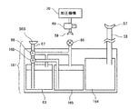
次に、本発明の第6実施形態について図10を参照して説明する。図10は同実施形態の要部模式的説明図である。 Next, a sixth embodiment of the present invention will be described with reference to FIG. FIG. 10 is a schematic explanatory diagram of a main part of the embodiment.
このインク洗浄充填ユニット181は、充填するインク中に溶け込む溶存気体を取り除いたインクを封入し密閉したインクボトル63と、洗浄液を封入した洗浄液ボトル165と、一連の洗浄液、インク充填により排出される洗浄液及びインクを回収する廃液ボトル164とをユニット化したものである。
The ink cleaning and filling
インクボトル63及び洗浄液ボトル165には、コンプレッサーや加圧ポンプなどの加圧機構70よる圧縮気体を用いて、圧力調整手段であるレギュレータ69を介して継手58によりタンクバルブ66に接続する構成としている。
The
レギュレータ69(圧力調整手段)は、インクボトル63内のインクを加圧する圧縮気体の圧力を調整するために設けている。この圧力値は、インク流路の抵抗や、作業環境温度変化によるインク粘度変化など、ヘッドユニット1内に流入するインクの流速を調整し、流路内の気泡を移動させやすくし,インクを確実に充填できるように適切に選ぶことができる。したがって、圧力調整手段は前記第4、第5実施形態に適用することも好ましい。
The regulator 69 (pressure adjusting means) is provided to adjust the pressure of the compressed gas that pressurizes the ink in the
なお、この実施形態によるインク充填動作は前記第4実施形態と同様である。 The ink filling operation according to this embodiment is the same as that of the fourth embodiment.
また、前記第4ないし第6実施形態において、はじめに洗浄液ボトル165から洗浄液を圧送せずに、三方切替弁168をインクボトル63から継手56Bへ連通させ、直接インクを流路内へ圧送させ、気泡を排出させてもよい。これにより、洗浄液を使用しないため、流路内のインクへの置換が不要になり、インク及び洗浄液の消費量を抑えることができ、コストダウンを図ることもができる。
In the fourth to sixth embodiments, first, the cleaning liquid is not pumped from the cleaning
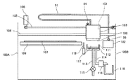
次に、上記各実施形態で説明したインク洗浄充填キットあるいはインク洗浄充填ユニットでインク洗浄充填を行う画像形成装置の一例について図11を参照して説明する。 Next, an example of an image forming apparatus that performs ink cleaning and filling with the ink cleaning and filling kit or the ink cleaning and filling unit described in the above embodiments will be described with reference to FIG.
この画像形成装置は、液体吐出ヘッドユニット1からなる記録ヘッド101を、キャリッジ103に搭載して、左右の側板100A、100B間に架け渡した主ガイドロッド104と図示しない副ガイド部材とで移動自在に支持している。
In this image forming apparatus, a
この記録ヘッド101は、タイミングベルト105を介して主走査モータ106によって主走査方向に移動走査される。
The
一方、被記録媒体107は記録ヘッド101のノズル面11aと対向し、記録ヘッド101の移動方向と直交する方向に搬送ローラ109によって搬送され、記録ヘッド101から画像に応じて吐出されるインク滴が付着されて画像が形成される。
On the other hand, the
記録ヘッド101へのインクの供給は、メインタンク5からフレキシブルなインク供給経路51によってなされる。
Ink is supplied to the
また、記録領域外に設けられたキャップ部材111は、複数のノズル11を有するノズル面108をキャッピングする弾性体、好ましくはシリコンゴム等からなる。非記録時には、記録ヘッド101がキャップ部材111の上方まで移動し、キャップ部材111が図示していないキャップ移動機構によって移動してノズル面108をキャッピングする。このキャップ部材111内には、インク吸引の際の吸引容易化、キャップ内雰囲気湿潤化等のため、インク吸収シート112が設けられている。
The
このキャップ部材111には、底面に2本のチューブ113、114が連結され、チューブ113は大気開放弁115を介して大気に連通される。チューブ114は吸引ポンプ116に接続され、キャップ部材111でノズル面108をキャッピングし、大気開放弁115を閉じた状態で、吸引ポンプ116を駆動してキャップ部材111内に負圧を発生させることで、記録ヘッド101のノズルからインクを吸引し、大気開放弁115を開放することでキャップ部材111内の空間117に溜まったインクを廃液タンク118に排出する。また、キャップ部材111は、大気開放弁115を閉じた状態でノズル面108に接触させ保持することで、記録ヘッド101のノズルの乾燥を防止する。
Two
さらに、図示していないワイパ移動機構によってワイパーブレード(ワイパ部材)119を記録ヘッド101のノズル面108に接触する高さまで移動させ、記録ヘッド101を主走査方向に移動させてワイパーブレード119によりノズル面108に付着したインクや塵埃を払拭し、ノズル面108のメニスカスの生成やクリーニングを行うことができる。
Further, a wiper blade (wiper member) 119 is moved to a height at which it contacts the
本画像形成装置においても、インク洗浄充填方法として,(A)タンク内へ気体を供給し液体収容タンク内の液体を排出させる工程、(B)タンク内の液体を全て排出させない状態から、他の液体を供給する工程、(C)タンク内を液体で満たす工程、を繰り返しながらヘッド及びタンク内の洗浄を行う。 Also in this image forming apparatus, as an ink cleaning and filling method, (A) a process of supplying gas into the tank and discharging the liquid in the liquid storage tank, (B) a state in which all the liquid in the tank is not discharged, The head and the tank are cleaned while repeating the step of supplying the liquid and the step (C) of filling the tank with the liquid.
ここで、(A)工程の後,圧縮気体及びインクボトル63のインク又は洗浄液ボトル65の洗浄液がヘッドユニット1へ供給されないように前記三方切替弁168を閉じ、ノズルからのインク垂れが止まった状態にし,タイミングベルト105を介して主走査モータ106によって主走査方向にヘッドユニット1(記録ヘッド101)に加減速の加速度を加えながら移動走査させると,タンク4内の液体は,慣性に従い加減方向と逆方向に移動し液体は攪拌される。
Here, after the step (A), the three-
これによりタンク4内の液体は更によどみがなくなり,ヘッド洗浄に使用する液体の低減,及び洗浄時間を短縮することができるようになる。
As a result, the liquid in the
なお,タンク4内の液体がHレベルである時よりもLレベルである時のほうが,タンク4の空間を利用して液体の攪拌が容易に行える。ただし、このLレベルのインク残量で大きな加減速を行うと,供給ポート24を通して共通液室13へ攪拌時に気泡が侵入するおそれがある。事前に気泡侵入が起きないインク残留レベルと加減速の値を調べておくと良い。
The liquid can be easily stirred using the space of the
なお、本願において、「用紙」とは材質を紙に限定するものではなく、OHP、布、ガラス、基板などを含み、インク滴、その他の液体などが付着可能なものの意味であり、被記録媒体、記録媒体、記録紙、記録用紙などと称されるものを含む。また、画像形成、記録、印字、印写、印刷はいずれも同義語とする。 In the present application, the “paper” is not limited to paper, but includes OHP, cloth, glass, a substrate, etc., and means a material to which ink droplets or other liquids can be attached. , Recording media, recording paper, recording paper, and the like. In addition, image formation, recording, printing, printing, and printing are all synonymous.
また、「画像形成装置」は、紙、糸、繊維、布帛、皮革、金属、プラスチック、ガラス、木材、セラミックス等の媒体に液体を吐出して画像形成を行う装置を意味し、また、「画像形成」とは、文字や図形等の意味を持つ画像を媒体に対して付与することだけでなく、パターン等の意味を持たない画像を媒体に付与すること(単に液滴を媒体に着弾させること)をも意味する。 The “image forming apparatus” means an apparatus that forms an image by discharging liquid onto a medium such as paper, thread, fiber, fabric, leather, metal, plastic, glass, wood, ceramics, etc. “Formation” means not only giving an image having a meaning such as a character or a figure to a medium but also giving an image having no meaning such as a pattern to the medium (simply causing a droplet to land on the medium). ) Also means.
また、「インク」とは、特に限定しない限り、インクと称されるものに限らず、記録液、定着処理液、液体などと称されるものなど、画像形成を行うことができるすべての液体の総称として用い、例えば、DNA試料、レジスト、パターン材料、樹脂なども含まれる。 The “ink” is not limited to an ink unless otherwise specified, but includes any liquid that can form an image, such as a recording liquid, a fixing processing liquid, or a liquid. Used generically, for example, includes DNA samples, resists, pattern materials, resins, and the like.
また、「画像」とは平面的なものに限らず、立体的に形成されたものに付与された画像、また立体自体を三次元的に造形して形成された像も含まれる。 In addition, the “image” is not limited to a planar image, and includes an image given to a three-dimensionally formed image and an image formed by three-dimensionally modeling a solid itself.
また、画像形成装置には、特に限定しない限り、シリアル型画像形成装置及びライン型画像形成装置のいずれも含まれる。 Further, the image forming apparatus includes both a serial type image forming apparatus and a line type image forming apparatus, unless otherwise limited.
1 液体吐出ヘッドユニット
2 ヘッド
4 ヘッドタンク
5 メインタンク
11 ノズル
13 共通液室
14 供給ポート
15 排出ポート
21 タンクケース
22 インク収容部
23 ダンパ部材(フィルム部材)
24 供給ポート
25 排出経路
39 排出流路
51 インク供給経路
53 インク戻り経路
54 開閉弁(バルブ)、
56、57 継手
61、161 インク洗浄充填ユニット
62 加圧用ボンベ
63 インクボトル
64、164 廃液ボトル
65 洗浄液ボトル
66 タンクバルブ
67 供給経路
68、168 三方切替弁
71、171 インク洗浄充填ユニット
81、181 インク洗浄充填ユニット
101 記録ヘッド(液体吐出ヘッドユニット)
DESCRIPTION OF
24
56, 57
Claims (10)
充填する前記液体を収容した液体収容手段と、
前記液体収容手段内の液体を加圧して前記液体を前記タンクの液体供給ポートに送液させる加圧手段と、
圧縮気体を前記タンクの液体供給ポートに圧送する手段と、を備え、
前記ヘッド及び前記タンク内の液体を入れ替えるときに、
前記タンク内へ前記圧縮気体を供給し、前記タンク内の液体を排出させ、
前記タンク内の前記液体が全て排出していない状態で、前記液体収容手段の前記液体を供給し、
供給した前記液体で前記タンクを満たす、ことを繰り返しながら、前記ヘッド及び前記タンク内の洗浄を行う
ことを特徴とする液体洗浄充填ユニット。 A liquid washing and filling unit for washing a head for discharging droplets and a tank for storing a liquid to be supplied to the head to fill the liquid,
Liquid storage means for storing the liquid to be filled;
Pressurizing means for pressurizing the liquid in the liquid storage means and feeding the liquid to the liquid supply port of the tank;
Means for pumping compressed gas to the liquid supply port of the tank,
When replacing the liquid in the head and the tank,
Supplying the compressed gas into the tank, and discharging the liquid in the tank;
In a state where all the liquid in the tank is not discharged, the liquid in the liquid storage means is supplied,
The liquid cleaning and filling unit is configured to perform cleaning of the head and the tank while repeatedly filling the tank with the supplied liquid.
ことを特徴とする請求項1に記載の液体洗浄充填ユニット。 The liquid cleaning and filling unit according to claim 1, further comprising recovered liquid storage means for recovering and storing the liquid discharged from the liquid discharge port of the tank.
充填する前記液体を収容した液体収容手段と、
前記液体よりも粘度の低い洗浄液を収容した洗浄液収容手段と、
前記液体収容手段内の液体と前記洗浄液収容手段内の洗浄液とを加圧して前記液体及び前記洗浄液を前記タンクの液体供給ポートに送液させる加圧手段と、
圧縮気体を前記タンクの液体供給ポートに圧送する手段と、を備え、
前記ヘッド及び前記タンク内の液体を入れ替えるときに、
前記タンク内へ前記圧縮気体を供給して前記タンク内の液体を排出させ、
前記タンク内の前記液体を全て排出させない状態から、前記洗浄液を供給し、
前記タンク内を前記洗浄液で満たす、ことを繰り返しながら、
前記ヘッド及び前記タンク内の洗浄を行う
ことを特徴とする液体洗浄充填ユニット。 A liquid filling unit that fills the liquid by cleaning a head that discharges droplets and a tank that stores liquid to be supplied to the head,
Liquid storage means for storing the liquid to be filled;
Cleaning liquid storage means for storing a cleaning liquid having a viscosity lower than that of the liquid;
Pressurizing means for pressurizing the liquid in the liquid storage means and the cleaning liquid in the cleaning liquid storage means to send the liquid and the cleaning liquid to the liquid supply port of the tank;
Means for pumping compressed gas to the liquid supply port of the tank,
When replacing the liquid in the head and the tank,
Supplying the compressed gas into the tank and discharging the liquid in the tank;
From a state where all the liquid in the tank is not discharged, the cleaning liquid is supplied,
While repeatedly filling the tank with the cleaning liquid,
A liquid cleaning and filling unit for cleaning the head and the tank.
ことを特徴とする請求項4記載の液体洗浄充填ユニット。 5. The liquid cleaning and filling unit according to claim 4, further comprising recovered liquid storage means for recovering and storing the liquid discharged from the liquid discharge port of the tank and the cleaning liquid.
充填する前記液体を収容した液体収容手段と、
前記液体収容手段内の液体を加圧して前記液体を前記タンクの液体供給ポートに送液させる加圧手段と、
圧縮気体を前記タンクの液体供給ポートに圧送する手段と、
前記タンクの液体排出ポートから排出される前記液体を回収して収容する回収液体収容手段と、を備えている液体洗浄充填ユニットを使用し、
前記タンク内へ前記圧縮気体を供給し、前記タンク内の液体を排出させる工程と、
前記タンク内の前記液体が全て排出していない状態で、前記液体収容手段の前記液体を供給する工程と、
供給した前記液体で前記タンクを満たす工程と、を繰り返しながら、前記ヘッド及び前記タンク内の洗浄を行って、前記液体を充填する
ことを特徴とする画像形成装置における液体洗浄充填方法。 A liquid cleaning and filling method for cleaning a head for discharging droplets of an image forming apparatus and a tank for storing a liquid to be supplied to the head and filling the liquid,
Liquid storage means for storing the liquid to be filled;
Pressurizing means for pressurizing the liquid in the liquid storage means and feeding the liquid to the liquid supply port of the tank;
Means for pumping compressed gas to the liquid supply port of the tank;
Using a liquid washing and filling unit comprising: a recovered liquid storage means for recovering and storing the liquid discharged from the liquid discharge port of the tank;
Supplying the compressed gas into the tank and discharging the liquid in the tank;
Supplying the liquid in the liquid storage means in a state where all the liquid in the tank is not discharged;
A liquid cleaning and filling method in an image forming apparatus, wherein the liquid is filled by cleaning the head and the tank while repeating the step of filling the tank with the supplied liquid.
充填する前記液体を収容した液体収容手段と、
前記液体よりも粘度の低い洗浄液を収容した洗浄液収容手段と、
前記液体収容手段内の液体と前記洗浄液収容手段内の洗浄液とを加圧して前記液体及び前記洗浄液を前記タンクの液体供給ポートに送液させる加圧手段と、
圧縮気体を前記タンクの液体供給ポートに圧送する手段と、
前記タンクの液体排出ポートから排出される前記液体及び前記洗浄液を回収して収容する回収液体収容手段と、を備えている液体洗浄充填ユニットを使用し、
前記タンク内へ前記圧縮気体を供給し、前記タンク内の液体を排出させる工程と、
前記タンク内の前記液体が全て排出していない状態で、前記洗浄液収容手段の前記洗浄液を供給する工程と、
供給した前記洗浄液で前記タンクを満たす工程と、を繰り返しながら、前記ヘッド及び前記タンク内の洗浄を行って、前記液体を充填する
ことを特徴とする画像形成装置における液体洗浄充填方法。 A liquid cleaning and filling method for cleaning a head for discharging droplets of an image forming apparatus and a tank for storing a liquid to be supplied to the head and filling the liquid,
Liquid storage means for storing the liquid to be filled;
Cleaning liquid storage means for storing a cleaning liquid having a viscosity lower than that of the liquid;
Pressurizing means for pressurizing the liquid in the liquid storage means and the cleaning liquid in the cleaning liquid storage means to send the liquid and the cleaning liquid to the liquid supply port of the tank;
Means for pumping compressed gas to the liquid supply port of the tank;
Using a liquid cleaning and filling unit comprising: the liquid discharged from the liquid discharge port of the tank and the recovered liquid storage means for recovering and storing the cleaning liquid;
Supplying the compressed gas into the tank and discharging the liquid in the tank;
Supplying the cleaning liquid in the cleaning liquid storage means in a state where all the liquid in the tank is not discharged;
A liquid cleaning and filling method in an image forming apparatus, wherein the liquid is filled by cleaning the head and the tank while repeating the step of filling the tank with the supplied cleaning liquid.
充填する前記液体を収容した液体収容手段と、
前記液体収容手段内の液体を加圧して前記液体を前記タンクの液体供給ポートに送液させる加圧手段と、
圧縮気体を前記タンクの液体供給ポートに圧送する手段と、
前記タンクの液体排出ポートから排出される前記液体を回収して収容する回収液体収容手段と、を備えている
ことを特徴とする液体洗浄充填キット。 A liquid filling kit for filling a liquid in a tank for containing a head for discharging droplets and a liquid to be supplied to the head;
Liquid storage means for storing the liquid to be filled;
Pressurizing means for pressurizing the liquid in the liquid storage means and feeding the liquid to the liquid supply port of the tank;
Means for pumping compressed gas to the liquid supply port of the tank;
A liquid cleaning and filling kit, comprising: recovered liquid storage means for recovering and storing the liquid discharged from the liquid discharge port of the tank.
充填する前記液体を収容した液体収容手段と、
前記液体よりも粘度の低い洗浄液を収容した洗浄液収容手段と、
前記液体収容手段内の液体と前記洗浄液収容手段内の洗浄液とを加圧して前記液体及び前記洗浄液を前記タンクの液体供給ポートに送液させる加圧手段と、
圧縮気体を前記タンクの液体供給ポートに圧送する手段と、
前記タンクの液体排出ポートから排出される前記液体及び前記洗浄液を回収して収容する回収液体収容手段と、を備えている
ことを特徴とする液体洗浄充填キット。 A cleaning and filling kit for filling a liquid in a tank for storing a head for discharging droplets and a liquid to be supplied to the head,
Liquid storage means for storing the liquid to be filled;
Cleaning liquid storage means for storing a cleaning liquid having a viscosity lower than that of the liquid;
Pressurizing means for pressurizing the liquid in the liquid storage means and the cleaning liquid in the cleaning liquid storage means to send the liquid and the cleaning liquid to the liquid supply port of the tank;
Means for pumping compressed gas to the liquid supply port of the tank;
A liquid cleaning and filling kit comprising: a recovery liquid storage means for recovering and storing the liquid discharged from the liquid discharge port of the tank and the cleaning liquid.
Priority Applications (1)
| Application Number | Priority Date | Filing Date | Title |
|---|---|---|---|
| JP2012032019A JP5954564B2 (en) | 2012-02-16 | 2012-02-16 | Apparatus including liquid cleaning and filling unit, liquid cleaning and filling method in image forming apparatus, and apparatus including liquid cleaning and filling kit |
Applications Claiming Priority (1)
| Application Number | Priority Date | Filing Date | Title |
|---|---|---|---|
| JP2012032019A JP5954564B2 (en) | 2012-02-16 | 2012-02-16 | Apparatus including liquid cleaning and filling unit, liquid cleaning and filling method in image forming apparatus, and apparatus including liquid cleaning and filling kit |
Publications (2)
| Publication Number | Publication Date |
|---|---|
| JP2013166344A true JP2013166344A (en) | 2013-08-29 |
| JP5954564B2 JP5954564B2 (en) | 2016-07-20 |
Family
ID=49177174
Family Applications (1)
| Application Number | Title | Priority Date | Filing Date |
|---|---|---|---|
| JP2012032019A Active JP5954564B2 (en) | 2012-02-16 | 2012-02-16 | Apparatus including liquid cleaning and filling unit, liquid cleaning and filling method in image forming apparatus, and apparatus including liquid cleaning and filling kit |
Country Status (1)
| Country | Link |
|---|---|
| JP (1) | JP5954564B2 (en) |
Cited By (7)
| Publication number | Priority date | Publication date | Assignee | Title |
|---|---|---|---|---|
| JP2016045083A (en) * | 2014-08-22 | 2016-04-04 | 株式会社リコー | Liquid detection device and liquid application device |
| JP2016179615A (en) * | 2015-03-24 | 2016-10-13 | ブラザー工業株式会社 | Cleaning liquid, cleaning liquid and ink set kit, ink jet recording apparatus, and ink tank cleaning method |
| CN107776204A (en) * | 2017-12-07 | 2018-03-09 | 北海市天硌打印耗材有限公司 | Remove bubble print cartridge |
| CN107953676A (en) * | 2017-12-07 | 2018-04-24 | 北海市天硌打印耗材有限公司 | Anti-bubble print cartridge |
| KR20190079070A (en) * | 2017-12-27 | 2019-07-05 | 주식회사 엘지화학 | Head cleaning method for ink-jet printer |
| JP2021030529A (en) * | 2019-08-21 | 2021-03-01 | 株式会社ミマキエンジニアリング | Liquid ejection device, liquid ejection method, and inkjet printer |
| JP2023178503A (en) * | 2019-04-05 | 2023-12-14 | キヤノン株式会社 | Recording device and method for controlling the same |
Citations (6)
| Publication number | Priority date | Publication date | Assignee | Title |
|---|---|---|---|---|
| JPH0781208A (en) * | 1993-09-14 | 1995-03-28 | Toray Ind Inc | Ink jet printing method and device therefor |
| JP2001058416A (en) * | 1999-08-23 | 2001-03-06 | Alps Electric Co Ltd | Method for processing to switch ink type in ink-jet printer |
| JP2001219579A (en) * | 2000-02-09 | 2001-08-14 | Seiko Epson Corp | Ink jet recording apparatus and method of cleaning print head |
| JP2004090432A (en) * | 2002-08-30 | 2004-03-25 | Seiko Epson Corp | Liquid ejecting apparatus, liquid discharging tank of liquid ejecting apparatus, and liquid discharging method of liquid ejecting apparatus |
| JP2011235470A (en) * | 2010-05-07 | 2011-11-24 | Ricoh Co Ltd | Image forming apparatus and liquid filling method in the same |
| JP2012006374A (en) * | 2010-05-21 | 2012-01-12 | Ricoh Co Ltd | Liquid filling unit, image forming apparatus, liquid filling method in image forming apparatus, liquid filling kit |
-
2012
- 2012-02-16 JP JP2012032019A patent/JP5954564B2/en active Active
Patent Citations (6)
| Publication number | Priority date | Publication date | Assignee | Title |
|---|---|---|---|---|
| JPH0781208A (en) * | 1993-09-14 | 1995-03-28 | Toray Ind Inc | Ink jet printing method and device therefor |
| JP2001058416A (en) * | 1999-08-23 | 2001-03-06 | Alps Electric Co Ltd | Method for processing to switch ink type in ink-jet printer |
| JP2001219579A (en) * | 2000-02-09 | 2001-08-14 | Seiko Epson Corp | Ink jet recording apparatus and method of cleaning print head |
| JP2004090432A (en) * | 2002-08-30 | 2004-03-25 | Seiko Epson Corp | Liquid ejecting apparatus, liquid discharging tank of liquid ejecting apparatus, and liquid discharging method of liquid ejecting apparatus |
| JP2011235470A (en) * | 2010-05-07 | 2011-11-24 | Ricoh Co Ltd | Image forming apparatus and liquid filling method in the same |
| JP2012006374A (en) * | 2010-05-21 | 2012-01-12 | Ricoh Co Ltd | Liquid filling unit, image forming apparatus, liquid filling method in image forming apparatus, liquid filling kit |
Cited By (11)
| Publication number | Priority date | Publication date | Assignee | Title |
|---|---|---|---|---|
| JP2016045083A (en) * | 2014-08-22 | 2016-04-04 | 株式会社リコー | Liquid detection device and liquid application device |
| JP2016179615A (en) * | 2015-03-24 | 2016-10-13 | ブラザー工業株式会社 | Cleaning liquid, cleaning liquid and ink set kit, ink jet recording apparatus, and ink tank cleaning method |
| CN107776204A (en) * | 2017-12-07 | 2018-03-09 | 北海市天硌打印耗材有限公司 | Remove bubble print cartridge |
| CN107953676A (en) * | 2017-12-07 | 2018-04-24 | 北海市天硌打印耗材有限公司 | Anti-bubble print cartridge |
| CN107776204B (en) * | 2017-12-07 | 2019-02-05 | 北海市天硌打印耗材有限公司 | de-bubble cartridge |
| CN107953676B (en) * | 2017-12-07 | 2019-06-21 | 北海市天硌打印耗材有限公司 | Anti-bubble cartridge |
| KR20190079070A (en) * | 2017-12-27 | 2019-07-05 | 주식회사 엘지화학 | Head cleaning method for ink-jet printer |
| KR102436922B1 (en) * | 2017-12-27 | 2022-08-26 | 주식회사 엘지화학 | Head cleaning method for ink-jet printer |
| JP2023178503A (en) * | 2019-04-05 | 2023-12-14 | キヤノン株式会社 | Recording device and method for controlling the same |
| US12304214B2 (en) | 2019-04-05 | 2025-05-20 | Canon Kabushiki Kaisha | Printing apparatus and ink quantity detection method thereof |
| JP2021030529A (en) * | 2019-08-21 | 2021-03-01 | 株式会社ミマキエンジニアリング | Liquid ejection device, liquid ejection method, and inkjet printer |
Also Published As
| Publication number | Publication date |
|---|---|
| JP5954564B2 (en) | 2016-07-20 |
Similar Documents
| Publication | Publication Date | Title |
|---|---|---|
| JP5954564B2 (en) | Apparatus including liquid cleaning and filling unit, liquid cleaning and filling method in image forming apparatus, and apparatus including liquid cleaning and filling kit | |
| JP5921136B2 (en) | Ink jet recording apparatus and logistics ink discharge method | |
| JP6019954B2 (en) | Image forming apparatus | |
| JP5487755B2 (en) | Liquid discharge head unit and image forming apparatus | |
| JP2009279901A (en) | Liquid discharge apparatus and image projection apparatus | |
| JP2020032620A (en) | Liquid jetting device, and maintenance method of the liquid jetting device | |
| JP5917083B2 (en) | Inkjet recording apparatus and maintenance method | |
| US10569559B2 (en) | Liquid ejecting apparatus | |
| JP2021109331A (en) | Liquid injection device, maintenance method of liquid injection device | |
| JP2011110828A (en) | Liquid storing tank, liquid discharge head unit, and image forming apparatus | |
| JP2011235470A (en) | Image forming apparatus and liquid filling method in the same | |
| JP2015231729A (en) | Inkjet printer | |
| JP2012096510A (en) | Fluid storage tank, fluid ejecting head unit and image forming apparatus | |
| JP7035460B2 (en) | Liquid injection device, maintenance method of liquid injection device | |
| JP2012006374A (en) | Liquid filling unit, image forming apparatus, liquid filling method in image forming apparatus, liquid filling kit | |
| JP6255964B2 (en) | Image forming apparatus | |
| JP2013188902A (en) | Image forming apparatus | |
| JP2012236292A (en) | Image forming apparatus | |
| JP2012143921A (en) | Maintenance apparatus, maintenance method, and liquid jetting apparatus | |
| JP6191295B2 (en) | Image forming apparatus | |
| JP6981179B2 (en) | Liquid injection device, maintenance method of liquid injection device | |
| JPH08150722A (en) | Image forming device | |
| JP2016010946A (en) | Liquid container, liquid ejection device, and liquid recovery method | |
| JP6167730B2 (en) | Image forming apparatus | |
| JPWO2018159044A1 (en) | RECOVERY SYSTEM OF PRINT HEAD, INKJET RECORDING DEVICE EQUIPPED WITH THE SAME, AND RECOVERY METHOD OF RECORD HEAD |
Legal Events
| Date | Code | Title | Description |
|---|---|---|---|
| A621 | Written request for application examination |
Free format text: JAPANESE INTERMEDIATE CODE: A621 Effective date: 20150119 |
|
| A977 | Report on retrieval |
Free format text: JAPANESE INTERMEDIATE CODE: A971007 Effective date: 20151028 |
|
| A131 | Notification of reasons for refusal |
Free format text: JAPANESE INTERMEDIATE CODE: A131 Effective date: 20151104 |
|
| A521 | Written amendment |
Free format text: JAPANESE INTERMEDIATE CODE: A523 Effective date: 20151215 |
|
| TRDD | Decision of grant or rejection written | ||
| A01 | Written decision to grant a patent or to grant a registration (utility model) |
Free format text: JAPANESE INTERMEDIATE CODE: A01 Effective date: 20160519 |
|
| A61 | First payment of annual fees (during grant procedure) |
Free format text: JAPANESE INTERMEDIATE CODE: A61 Effective date: 20160601 |
|
| R151 | Written notification of patent or utility model registration |
Ref document number: 5954564 Country of ref document: JP Free format text: JAPANESE INTERMEDIATE CODE: R151 |