JP2013166302A - Inkjet recording apparatus - Google Patents
Inkjet recording apparatus Download PDFInfo
- Publication number
- JP2013166302A JP2013166302A JP2012030833A JP2012030833A JP2013166302A JP 2013166302 A JP2013166302 A JP 2013166302A JP 2012030833 A JP2012030833 A JP 2012030833A JP 2012030833 A JP2012030833 A JP 2012030833A JP 2013166302 A JP2013166302 A JP 2013166302A
- Authority
- JP
- Japan
- Prior art keywords
- ink
- recording apparatus
- housing
- jet recording
- ink jet
- Prior art date
- Legal status (The legal status is an assumption and is not a legal conclusion. Google has not performed a legal analysis and makes no representation as to the accuracy of the status listed.)
- Withdrawn
Links
Images

Landscapes
- Ink Jet (AREA)
Abstract
Description
本発明は、ファクシミリやプリンターに代表されるインクジェット記録装置に関し、特に記録ヘッドを備えるとともに所定の移動方向に移動可能なヘッドユニットと、当該ヘッドユニットから独立したインク収容部と、ヘッドユニットとインク収容部との間のインク流路を形成するインクチューブと、を備えたインクジェット記録装置に関する。 The present invention relates to an inkjet recording apparatus typified by a facsimile or a printer, and in particular, a head unit that includes a recording head and is movable in a predetermined movement direction, an ink storage unit independent of the head unit, a head unit, and an ink storage The present invention relates to an ink jet recording apparatus that includes an ink tube that forms an ink flow path between the first and second portions.
ファクシミリやプリンターに代表される記録装置、その中でも特にインクジェット記録装置には、インクを吐出する記録ヘッドを備えるとともに所定の移動方向に移動可能なヘッドユニット(キャリッジと呼ばれる場合もある)を備えた、所謂シリアル式のインクジェット記録装置がある。 A recording apparatus typified by a facsimile or a printer, in particular an inkjet recording apparatus, includes a recording head for ejecting ink and a head unit (sometimes referred to as a carriage) that can move in a predetermined movement direction. There is a so-called serial type ink jet recording apparatus.
ここで、ヘッドユニットには、インクを収容するインク収容部(以下では適宜「インクカートリッジ」と言う)を搭載するものと、インクカートリッジを搭載しないものとがある。 Here, the head unit includes an ink storage unit (hereinafter referred to as an “ink cartridge” as appropriate) that stores ink, and a head unit that does not include an ink cartridge.
ヘッドユニットにインクカートリッジを搭載するものは、ヘッドユニットはインクカートリッジを搭載した状態で所定方向に往復動し、ヘッドユニット内部で、インクカートリッジから記録ヘッドへとインクが供給される。インクカートリッジを搭載しないものは、インクカートリッジがヘッドユニットから独立して設けられ、インクカートリッジとヘッドユニット(記録ヘッド)とは、インク供給用のインクチューブによって連通される(例えば、特許文献1)。 In the case where an ink cartridge is mounted on the head unit, the head unit reciprocates in a predetermined direction with the ink cartridge mounted, and ink is supplied from the ink cartridge to the recording head inside the head unit. In the case where the ink cartridge is not mounted, the ink cartridge is provided independently from the head unit, and the ink cartridge and the head unit (recording head) are communicated with each other by an ink tube for supplying ink (for example, Patent Document 1).
インクチューブは或る程度の長さを有しており、装置内部で他の構成要素の邪魔にならない様に引き回され、適宜の場所で固定されている。
しかし、ヘッドユニットにおいてインクチューブが延出する位置が高い位置にあり、そしてヘッドユニットから延出して引き回されるインクチューブが前記延出する位置より低い位置にあると、水頭差の原理によってインクを前記延出する位置まで引き揚げる為に必要なエネルギーが多く必要となる。従ってヘッドユニットにおいてインクチューブが延出する位置は、極力低い部分に設けられることが好ましいが、従来のインクジェットプリンターでは必ずしも上記課題については考慮されていなかった。
The ink tube has a certain length, is routed so as not to interfere with other components inside the apparatus, and is fixed at an appropriate place.
However, if the position where the ink tube extends in the head unit is at a high position, and the ink tube extended from the head unit is located at a position lower than the extending position, the ink head may be moved according to the principle of water head difference. A large amount of energy is required to lift the to the extended position. Therefore, it is preferable that the position where the ink tube extends in the head unit is provided as low as possible. However, the conventional inkjet printer does not necessarily consider the above-described problem.
そこで本発明はこの様な状況に鑑みなされたものであり、その目的は、インクチューブをヘッドユニットの極力低い位置から延出させることにある。 Accordingly, the present invention has been made in view of such a situation, and an object thereof is to extend the ink tube from a position as low as possible of the head unit.
上記課題を解決する為の、本発明の第1の態様に係るインクジェット記録装置は、インクを吐出する記録ヘッドおよびインクが収容されたインク収容部と前記記録ヘッドとを中継する中継部を備え、前記記録ヘッドの走査方向に移動可能な筐体と、前記インク収容部から送られるインクを前記記録ヘッドへと導く、可撓性を有するインクチューブと、を備え、前記筐体の周囲を構成する壁には、上部に切欠部が形成されており、前記インクチューブが、前記切欠部を通って前記筐体の外側に延出していることを特徴とする。 In order to solve the above problems, an ink jet recording apparatus according to a first aspect of the present invention includes a recording head that ejects ink, an ink storage unit that stores ink, and a relay unit that relays the recording head. A casing that is movable in the scanning direction of the recording head; and a flexible ink tube that guides ink sent from the ink storage unit to the recording head, and constitutes a periphery of the casing. The wall is formed with a notch at the top, and the ink tube extends to the outside of the housing through the notch.
本態様によれば、記録ヘッドを備える筐体の周囲を構成する壁には、上部に切欠部が形成されており、インクチューブが、前記切欠部を通って前記筐体の外側に延出しているので、前記インクチューブをより低い位置で前記中継部から延出させることができ、記録ヘッドへのインク供給の観点でより好ましい構成を構築できる。 According to this aspect, the wall constituting the periphery of the housing including the recording head has the notch formed in the upper portion, and the ink tube extends to the outside of the housing through the notch. Therefore, the ink tube can be extended from the relay section at a lower position, and a more preferable configuration can be constructed from the viewpoint of supplying ink to the recording head.
本発明の第2の態様に係るインクジェット記録装置は、インクを吐出する記録ヘッドおよびインクが収容されたインク収容部と前記記録ヘッドとを中継する中継部を備え、前記記録ヘッドの走査方向に移動可能な筐体と、前記インク収容部から送られるインクを前記記録ヘッドへと導く、可撓性を有するインクチューブと、を備え、前記筐体の周囲を構成する壁には、上部に凹部が形成されており、前記インクチューブが、前記凹部を通って前記筐体の外側に延出していることを特徴とする。 An ink jet recording apparatus according to a second aspect of the present invention includes a recording head that discharges ink, an ink storage unit that stores ink, and a relay unit that relays the recording head, and moves in the scanning direction of the recording head. And a flexible ink tube that guides ink sent from the ink container to the recording head, and a wall that forms the periphery of the casing has a recess at the top. The ink tube is formed to extend outside the casing through the recess.
本態様によれば、記録ヘッドを備える筐体の周囲を構成する壁には、上部に凹部が形成されており、インクチューブが、前記凹部を通って前記筐体の外側に延出しているので、前記インクチューブをより低い位置で前記中継部から延出させることができ、記録ヘッドへのインク供給の観点でより好ましい構成を構築できる。 According to this aspect, the wall constituting the periphery of the casing including the recording head has the recess formed in the upper portion, and the ink tube extends to the outside of the casing through the recess. The ink tube can be extended from the relay portion at a lower position, and a more preferable configuration can be constructed from the viewpoint of supplying ink to the recording head.
本発明の第3の態様に係るインクジェット記録装置は、インクを吐出する記録ヘッドおよびインクが収容されたインク収容部と前記記録ヘッドとを中継する中継部を備え、前記記録ヘッドの走査方向に移動可能な筐体と、前記インク収容部から送られるインクを前記記録ヘッドへと導く、可撓性を有するインクチューブと、を備え、前記筐体の周囲を構成する壁には、上部に段差が形成されており、前記インクチューブが、前記段差を通って前記筐体の外側に延出していることを特徴とする。 An ink jet recording apparatus according to a third aspect of the present invention includes a recording head that discharges ink, an ink storage unit that stores ink, and a relay unit that relays the recording head, and moves in the scanning direction of the recording head. And a flexible ink tube that guides the ink sent from the ink container to the recording head, and the wall that forms the periphery of the casing has a step at the top. The ink tube is formed to extend outside the casing through the step.
本態様によれば、記録ヘッドを備える筐体の周囲を構成する壁には、上部に段差が形成されており、インクチューブが、前記段差を通って前記筐体の外側に延出しているので、前記インクチューブをより低い位置で前記中継部から延出させることができ、記録ヘッドへのインク供給の観点でより好ましい構成を構築できる。 According to this aspect, the wall constituting the periphery of the housing including the recording head has a step formed at the top, and the ink tube extends outside the housing through the step. The ink tube can be extended from the relay portion at a lower position, and a more preferable configuration can be constructed from the viewpoint of supplying ink to the recording head.
本発明の第4の態様に係るインクジェット記録装置は、インクを吐出する記録ヘッドおよびインクが収容されたインク収容部と前記記録ヘッドとを中継する中継部を備え、前記記録ヘッドの走査方向に移動可能な筐体と、前記インク収容部から送られるインクを前記記録ヘッドへと導く、可撓性を有するインクチューブと、を備え、前記筐体の周囲を構成する壁には、上部に切欠部が形成されており、前記インクチューブが、前記切欠部の底辺の上から前記筐体の外側に延出していることを特徴とする。 An ink jet recording apparatus according to a fourth aspect of the present invention includes a recording head that ejects ink, an ink storage unit that stores ink, and a relay unit that relays the recording head, and moves in the scanning direction of the recording head. And a flexible ink tube that guides ink sent from the ink container to the recording head, and a wall that forms the periphery of the casing has a notch at the top. The ink tube extends from the bottom of the notch to the outside of the housing.
本態様によれば、記録ヘッドを備える筐体の周囲を構成する壁には、上部に切欠部が形成されており、インクチューブが、前記切欠部の底辺の上から前記筐体の外側に延出しているので、前記インクチューブをより低い位置で前記中継部から延出させることができ、記録ヘッドへのインク供給の観点でより好ましい構成を構築できる。 According to this aspect, the wall constituting the periphery of the casing including the recording head has the notch formed in the upper portion, and the ink tube extends from the top of the notch to the outside of the casing. Since the ink tube is discharged, the ink tube can be extended from the relay portion at a lower position, and a more preferable configuration can be constructed from the viewpoint of supplying ink to the recording head.
本発明の第5の態様は、第1の態様において、記録が行われた被記録媒体が排出される排出口が設けられた側を装置前方側としたときに、前記壁は、前記筐体の周囲を構成する壁のうち前方側の壁であり、前記インクチューブが、前記中継部から装置前方側に向かって延出した後、前記ヘッドユニットの移動方向に向かって延びた状態となっている、ことを特徴とする。 According to a fifth aspect of the present invention, in the first aspect, when the side provided with the discharge port for discharging the recording medium on which recording is performed is the front side of the apparatus, the wall is the housing The ink tube extends from the relay portion toward the front side of the apparatus and then extends toward the moving direction of the head unit. It is characterized by that.
本発明の第6の態様は、第1の態様において、前記筐体が、当該筐体からの前記インクチューブの延出方向に前記インクチューブを案内する案内部を備える、ことを特徴とする。 According to a sixth aspect of the present invention, in the first aspect, the casing includes a guide portion that guides the ink tube in a direction in which the ink tube extends from the casing.
本発明の第7の態様は、第1の態様において、前記インクチューブが、当該インクチューブの前記筐体からの延出方向を規定する規定手段により前記筐体からの延出方向が規定されている、ことを特徴とする。 According to a seventh aspect of the present invention, in the first aspect, the extending direction of the ink tube from the housing is defined by a defining unit that defines the extending direction of the ink tube from the housing. It is characterized by that.
本発明の第8の態様は、第1の態様において、前記インクチューブを複数本有し、当該複数本のインクチューブが、上下方向に配列されて前記筐体から延出する、ことを特徴とする。 According to an eighth aspect of the present invention, in the first aspect, the ink tube includes a plurality of the ink tubes, and the plurality of ink tubes are arranged in a vertical direction and extend from the housing. To do.
本発明の第9の態様は、第1の態様において、前記インクチューブを複数本有し、当該複数本のインクチューブが、水平方向に配列されて前記筐体から延出する、ことを特徴とする。 According to a ninth aspect of the present invention, in the first aspect, the ink tube includes a plurality of ink tubes, and the plurality of ink tubes are arranged in a horizontal direction and extend from the housing. To do.
本発明の第10の態様は、第1の態様において、前記筐体の移動領域における少なくとも一部の移動領域上部を露呈させる開口部を備えたハウジングを備え、前記インクチューブを複数本有し、当該複数本のインクチューブが、前記ハウジングの上面において横方向に配列されて前記ハウジングの上面に固定されている、ことを特徴とする。 According to a tenth aspect of the present invention, in the first aspect, the housing includes a housing having an opening that exposes at least a part of the upper part of the moving region in the moving region of the housing, and includes a plurality of the ink tubes. The plurality of ink tubes are arranged in a lateral direction on the upper surface of the housing and fixed to the upper surface of the housing.
本発明の第11の態様は、第1の態様において、前記インクチューブを複数本備えるとともに、当該複数本のインクチューブの配列方向を変換する配列変換部により、複数の前記インクチューブの配列方向が水平方向から上下方向に、或いは上下方向から水平方向に変換される、ことを特徴とする。 According to an eleventh aspect of the present invention, in the first aspect, the arrangement includes a plurality of the ink tubes, and the arrangement direction of the plurality of ink tubes is changed by the arrangement conversion unit that converts the arrangement direction of the plurality of ink tubes. It is characterized in that it is converted from the horizontal direction to the vertical direction or from the vertical direction to the horizontal direction.
本発明の第12の態様は、第1の態様において、前記インクチューブを複数本備えるとともに、当該複数本のインクチューブが結束手段によって結束されている、ことを特徴とする。 A twelfth aspect of the present invention is characterized in that, in the first aspect, a plurality of the ink tubes are provided, and the plurality of ink tubes are bound by a binding means.
本発明の第13の態様は、第1の態様において、前記筐体に、当該筐体の上部を開閉可能なカバーが設けられていることを特徴とする。 According to a thirteenth aspect of the present invention, in the first aspect, the casing is provided with a cover capable of opening and closing an upper portion of the casing.
本発明の第14の態様は、第1の態様において、前記中継部に把持部が設けられている
ことを特徴とする。
A fourteenth aspect of the present invention is characterized in that, in the first aspect, a grip portion is provided in the relay portion.
本発明の第15の態様は、第14の態様において、前記切欠部が前記把持部より下方に位置していることを特徴とする。 According to a fifteenth aspect of the present invention, in the fourteenth aspect, the notch is positioned below the gripping part.
本発明の第16の態様は、第1の態様において、前記中継部を複数備え、前記中継部から前記インクチューブが延出する延出部の高さ位置が、複数の前記中継部の間において異なることを特徴とする。 According to a sixteenth aspect of the present invention, in the first aspect, a plurality of the relay portions are provided, and a height position of the extension portion where the ink tube extends from the relay portion is between the plurality of the relay portions. It is characterized by being different.
本発明の第17の態様は、第16の態様において、複数の前記延出部が、所定方向に向かって順次斜め下に位置していることを特徴とする。 The seventeenth aspect of the present invention is characterized in that, in the sixteenth aspect, the plurality of extending portions are sequentially positioned obliquely downward in a predetermined direction.
本発明の第18の態様は、第17の態様において、前記切欠部の底辺が、複数の前記延出部の高さ位置の変化に従って斜め下方に延びていることを特徴とする。 According to an eighteenth aspect of the present invention, in the seventeenth aspect, the bottom of the notch extends obliquely downward according to a change in the height position of the plurality of extending portions.
本発明の第19の態様は、第1から第18の態様のいずれかにおいて、前記ハウジングの外側に前記インク収容部を備えていることを特徴とする。 According to a nineteenth aspect of the present invention, in any one of the first to eighteenth aspects, the ink containing portion is provided outside the housing.
以下、本発明の一実施形態を図面に基づいて説明するが、本発明は、以下説明する実施形態に限定されることなく、特許請求の範囲に記載した発明の範囲内で種々の変形が可能であり、それらも本発明の範囲内に含まれるものであることを前提として、以下本発明の一実施形態を説明するものとする。 DESCRIPTION OF EXEMPLARY EMBODIMENTS Hereinafter, an embodiment of the invention will be described with reference to the drawings. However, the invention is not limited to the embodiment described below, and various modifications are possible within the scope of the invention described in the claims. Assuming that these are also included in the scope of the present invention, one embodiment of the present invention will be described below.
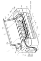
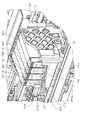
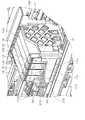
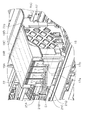
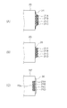
図1は、本発明に係るインクジェット記録装置の一例としてのインクジェットプリンターの第1実施形態を示す外観斜視図であり、図2はヘッドユニット15Aの拡大斜視図である。また図3は本発明の第2実施形態に係るインクジェットプリンターにおける、ヘッドユニット15Bの外観斜視図、図4は本発明の第3実施形態に係るインクジェットプリンターにおける、ヘッドユニット15Cの外観斜視図、図5は本発明の第4実施形態に係るインクジェットプリンターにおける、ヘッドユニット15Dの外観斜視図である。
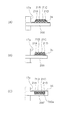
更に図6(A)、(B)、(C)及び図7(A)、(B)、(C)はガイド部材を側面視した際のインクチューブ21の固定方法のバリエーションを示す図である。尚、全ての図において図面上方向が鉛直上方向である。
FIG. 1 is an external perspective view showing a first embodiment of an ink jet printer as an example of an ink jet recording apparatus according to the present invention, and FIG. 2 is an enlarged perspective view of a head unit 15A. 3 is an external perspective view of the
Further, FIGS. 6A, 6B, and 7C, and FIGS. 7A, 7B, and 7C are views showing variations of the fixing method of the
以下、図1及び図2を参照しつつインクジェットプリンターの全体構成について概説する。
図1において、インクジェットプリンター1は、媒体の一例としての記録用紙にインクジェット記録を行う記録装置であり、装置本体2の外観が、ハウジング(筐体)30により構成されている。
The overall configuration of the ink jet printer will be outlined below with reference to FIGS. 1 and 2.
In FIG. 1, an inkjet printer 1 is a recording apparatus that performs inkjet recording on a recording sheet as an example of a medium, and an external appearance of the apparatus body 2 is configured by a housing (housing) 30.
ハウジング30の上部には開口部(開口領域)30aが形成されている。この開口部30aは、後述するヘッドユニット15Aの移動領域における少なくとも一部の移動領域上部を露呈させる開口である。ヘッドユニット15Aは、移動領域の右端(図1)或いは左端に位置する際は、その上部の一部がハウジング30の下側に隠れるが、移動領域の右端或いは左端から中央側に移動することにより、上部の全部が露呈する。
An opening (opening region) 30 a is formed in the upper portion of the
開口部30aにはカバー3が開閉可能に設けられており、カバー3を開くことにより、紙ジャムが生じた際のジャム処理作業(用紙の取り除き作業)を、開口部30aを介して行える様になっている。尚、本実施形態ではカバー3が設けられているが、カバー3を設けずに、開口部30aを開放したままの状態としても良い。
The
装置後方側には用紙を給送する給送部(詳細不図示)が設けられており、符号12は用紙を差し入れる差し込み口である給紙口を示している。この給紙口12の内部には、セットされた用紙を給送する給送ローラー(不図示)が設けられている。尚、符号13は用紙幅方向に変位可能に設けられた、用紙側端をガイドするエッジガイドを示している。
A feeding unit (not shown in detail) for feeding paper is provided on the rear side of the apparatus, and
装置前方側には記録が行われた用紙が排出される排紙口5が構成されており、この排紙口5の下側には排出された用紙を受ける排紙受けトレイ6が設けられている。排紙受けトレイ6は引き出し式に構成され、図1は収納された状態を示している。
装置上面において符号9は、電源ボタンや各種印刷設定・記録実行を行う操作ボタン、印刷設定内容や印刷画像のプレビュー表示などを行う表示部、等を備えて成る操作パネルである。
On the front side of the apparatus, there is a
装置内部において符号15Aはヘッドユニット(キャリッジと呼ばれる場合もある)であり、このヘッドユニット15Aの底部にインクを吐出する記録ヘッド16が設けられている。ヘッドユニット15Aが用紙幅方向に移動する過程において記録ヘッド16からインクが吐出されることにより、用紙に記録が実行される。
In the apparatus,
続いて、記録ヘッド16へインクを供給するインク供給系について説明する。本実施形態に係るヘッドユニット15Aはインクカートリッジを搭載しておらず、ハウジング30の側面に取り付けられたインクタンク32(32A〜32D)から、インク流路を形成する流路形成部材としてのインクチューブ21(21A〜21D)を介して、記録ヘッド16へとインクを供給する様に構成されている。
Next, an ink supply system that supplies ink to the
より詳しくは、インクタンク32A〜32Dは、それぞれ異なる色のインクを収容するインク収容部であり、例えばインクタンク32Aはブラック(BK)のインクを、インクタンク32Bはイエロー(Y)のインクを、インクタンク32Cはマゼンタ(M)のインクを、インクタンク32Dはシアン(C)のインクを、それぞれ収容する。
More specifically, the
インクチューブ21A〜21Dは可撓性を有するチューブであり、インクタンク32A〜32Dから記録ヘッド16に至るインク流路を形成する。尚、ヘッドユニット15Aは、中継アダプター収容部17が筐体を構成し、この中継アダプター収容部(筐体)17により本体が構成されており、この中継アダプター収容部17に、各インク色に対応した「中継部」としての中継アダプター19A〜19Dが収容されている。
The
中継アダプター19A〜19Dは、記録ヘッド16とインクタンク32A〜32Dとを中継するアダプターであり、インクチューブ32A〜32Dは、それぞれ中継アダプター19A〜19Dに接続されている。換言すれば、中継アダプター19A〜19Dから、ヘッドユニット15Aの外側にインクチューブ32A〜32Dが延出した状態となっている。尚、中継アダプター19A〜19Dの上部前方側(後述する切欠部17bより上方)には凹凸形状により構成された把持部(グリップ部)18が形成されており、中継アダプター19A〜19Dの装着及び取り外し作業時に把持する性の容易性が確保されている。但し、中継アダプター19A〜19Dは、ヘッドユニット15Aに対し着脱可能に構成しても、或いは固定的に設けても、いずれであっても構わない。
The
尚、以下ではインクタンク32A〜32Dを特に区別する必要の無い場合には「インクタンク32」と呼び、同様にインクチューブ21A〜21Dを特に区別する必要の無い場合には「インクチューブ21」と呼び、中継アダプター19A〜19Dを特に区別する必要の無い場合には「中継アダプター19」と呼ぶこととする。
In the following description, the
■■■第1実施形態■■■
以下、インクチューブ21のヘッドユニット15Aからの延出形態について説明する。各実施形態において共通する特徴として、インクチューブ21は、中継アダプター収容部17の周囲を構成する壁17aの上部に形成された切欠部17bを通ってヘッドユニット15Aの外側に延出する。
■■■ First embodiment ■■■
Hereinafter, the extension form of the
より詳しくは、図2において中継アダプター収容部17の周囲を構成する壁のうち、本実施形態では前方側の壁17a、即ち排紙口5が形成された側を装置前方側とした際に中継アダプター収容部17の前方側の壁17aの、上部に切欠部17bが形成されている。
More specifically, among the walls constituting the periphery of the relay
切欠部17bは、複数収容された中継アダプター19A〜19Dの前方側の面をより多く下側まで露呈させる様に切り欠かれている。そしてこの切欠部17bを通って(切欠部17bの底辺の上を通って)、インクチューブ21がヘッドユニット15Aの外側(中継アダプター収容部17の外側)に延出した状態となっている。符号T1〜T2は、中継アダプター19A〜19Dのそれぞれにおいてインクチューブ21が延出する延出位置(延出部)を示している。尚、切欠部17bは、凹状に形成されていることから凹部と言うこともでき、或いは段差とも言うこともできる。
The
インクチューブ21は、より具体的には中継アダプター19から装置前方側に向かって延出した後、記録ヘッド16の走査方向(ヘッドユニット15Aの移動方向)に向かって延びている。
More specifically, the
以上の構成により、以下の作用効果が得られる。即ち、ヘッドユニット15Aにおいてインクチューブ21が延出する延出位置T1〜T4が高く、そしてヘッドユニット15Aから延出して引き回されるインクチューブ21が延出位置T1〜T4より低い位置にあると、水頭差の原理によってインクを延出位置T1〜T4まで引き揚げる為に必要なエネルギーが多く必要となる。従って延出位置T1〜T4は、極力低い部分に設けられることが好ましい。
With the above configuration, the following operational effects can be obtained. That is, in the
そして本実施形態においては、上述の様に中継アダプター収容部17の壁17aの上部に切欠部17bが形成されており、延出位置T1〜T4が切欠部17bを利用して配置されているので、延出位置T1〜T4を低い位置に配置することができ、インク供給の観点でより好ましいヘッドユニット15Aを構成することができる。
In the present embodiment, as described above, the
尚、延出位置T1〜T4が切欠部17bを利用しているとは、インクチューブ21が全て切欠部17bの内側から延出している形態のみならず、一部が切欠部17bを利用している形態も含む意味である。例えば、インクチューブ21の外径のうち少なくとも一部が切欠部17bに入り込んでいれば、インクチューブ21は切欠部17bを利用して延出していることとなる。或いは、複数本のインクチューブ21A〜21Dのうち少なくとも1本が切欠部17bを利用して延出していれば、インクチューブ21は切欠部17bを利用して延出していることとなる。
Note that the extending positions T1 to T4 use the
尚、本実施形態では、ヘッドユニット15Aから延出したインクチューブ21は、ヘッドユニット15Aの近傍で結束部材27により上下方向に配列された状態で結束される。そして、インクチューブ21はハウジング30の前面上部の壁30bに対し上下方向に配列された状態で固定部25により固定される。
In the present embodiment, the
またインクチューブ21は、ハウジング30の左上面において固定部26により横方向に配列された状態でハウジング30の左上面に固定され、インクタンク32へと向かう。従って固定部26は、インクチューブ21の配列方向を縦方向から横方向に変換する配列変換部を構成する。或いは、固定部25は、インクチューブの配列方向を横方向から縦方向に変換する配列変換部を構成する。
The
また、本実施形態においてインクチューブ21は、固定部25とヘッドユニット15A(より具体的には中継アダプター19)との間におけるインクチューブ21の引き回し区間C1において、ヘッドユニット15Aの移動動作に伴って変形する様になっている。インクタンク32と固定部25との間におけるインクチューブ21の引き回し区間C2では、ヘッドユニット15Aの移動動作に伴う変形は殆ど生じない。
Further, in the present embodiment, the
尚、本実施形態ではインクチューブ21は開口部31aの左側(装置前方側から見て左側)からハウジング30の外に出ているが、開口部31aの右側からハウジング30の外に出ても良い。この場合、インクタンク32は装置右側に取り付けても良い。
In this embodiment, the
■■■第2実施形態■■■
続いて図3を参照しつつ第2実施形態に係るヘッドユニット15Bについて説明する。本実施形態に係るヘッドユニット15Bが上述した第1実施形態と異なるのは、中継アダプター収容部17の側面にガイド部材20を備え、このガイド部材20に対しインクチューブ21が固定される点である。尚、ヘッドユニット15Bを除く他のプリンターの構造は、上述した第1実施形態と同様である(以降説明する他の実施形態でも同様)。
■■■ Second Embodiment ■■■
Next, the
ガイド部材20は中継アダプター収容部17の前方側の壁17aよりもやや前方側に突出する様に、中継アダプター収容部17の側面に取り付けられており、インクチューブ21は、ガイド部材20の先端に、縦方向に配列された状態で固定される。符号34はインクチューブ21をガイド部材20に固定する固定手段の一例である接着テープを示しており、インクチューブ21は、ガイド部材20の先端に、接着テープ34により固定される。
The
以上により、ガイド部材20は、インクチューブ21をチューブ延出方向(本実施形態では、ヘッドユニット15Bの移動方向)に案内する案内部として機能する。或いは、ガイド部材20は、インクチューブ21のヘッドユニット15Bからの延出方向を規定する規定手段として機能する。
As described above, the
■■■第3実施形態■■■
続いて図4を参照しつつ第3実施形態に係るヘッドユニット15Cについて説明する。本実施形態に係るヘッドユニット15Cが上述した第1、第2実施形態と異なるのは、中継アダプター収容部17の上部に中継アダプター収容部17の上方を開閉可能なカバー22が設けられている点である。このカバー22は、軸22a(図4では、中継アダプター収容部17の両側に設けられた軸22aのうち、一方側が示されている)を中心に回動可能に設けられており、回動することにより、中継アダプター収容部17の上方を開閉する。これにより中継アダプター収容部17の内部への塵埃等の侵入が抑制される。
■■■ Third embodiment ■■■
Next, a head unit 15C according to the third embodiment will be described with reference to FIG. The head unit 15C according to this embodiment is different from the first and second embodiments described above in that a
■■■第4実施形態■■■
続いて図5を参照しつつ第4実施形態に係るヘッドユニット15Dについて説明する。本実施形態に係るヘッドユニット15Dが上述した第1〜第3実施形態と異なるのは、第1に中継アダプター19A’〜19D’のそれぞれにおいてインクチューブ21が延出する延出位置(延出部)T1’〜T4’が、図の右方に向かって順次斜め下に位置している。
■■■ Fourth Embodiment ■■■
Next, a
そして本実施形態に係るヘッドユニット15Dが上述した第1〜第3実施形態と異なるのは、第2に中継アダプター収容部17’の前方側の壁17a’に形成された切欠部17b’の底辺が、延出位置T1’〜T4’の高さ位置の変化に従って斜め下方に下がる傾斜面となっている。以上の様に構成されたことにより、インクチューブ21を縦方向に配列した状態で延出させる際に、複数本のインクチューブ21が重ならず、自然に延出させることができる。
The difference between the
■■■構成要素のバリエーション■■■
以上説明した各実施形態は一例であり、本発明はこれら各実施形態に限られない。例えば、以上説明し各実施形態における各構成要素は、以下の様なバリエーションを取りうる。但し、以下のバリエーションは一例であり、本発明が以下に記載されたバリエーションに限定されないことは言うまでもない。
■■■ Variations of components ■■■
Each embodiment described above is an example, and the present invention is not limited to each embodiment. For example, the constituent elements in the embodiments described above can take the following variations. However, the following variations are merely examples, and it goes without saying that the present invention is not limited to the variations described below.
(1)複数本のインクチューブ21を結束する結束部材27(図2)には、紐、ゴムバンド、クリップ等、種々のものを採用できる。またインクチューブ21は、図2に示した位置のほか、適宜の場所で結束することができる。
(1) As the bundling member 27 (FIG. 2) for bundling a plurality of
(2)インクチューブ21をガイド部材20に固定する際の固定手段には、図3に示した接着テープ34のほか、両面テープや接着剤などによるその他の接着固定、紐、ゴムバンドなどによる固定、クリップ、その他部材を利用した固定、など種々の固定方法を用いることができる。
(2) As a fixing means when fixing the
図6(A)〜(C)はその一例を示すものである。図6(A)は上述した様にインクチューブ21を接着テープ34によりガイド部材20に固定する例であり、図6(B)は接着剤(又は両面テープ)35によりインクチューブ21をガイド部材20に固定する例である。また、図6(C)に示すガイド部材20’は凹部20aが形成されており、この凹部20aにインクチューブ21が収容されるとともに、蓋部材36によってインクチューブ21が保持された状態となっている。
FIGS. 6A to 6C show an example. FIG. 6A shows an example in which the
図7(A)〜(C)は、ガイド部材にインクチューブ21を横配列する例であり、図7(A)はインクチューブ21を接着テープ34によりガイド部材200に横配列状態で固定する例であり、図7(B)は接着剤(又は両面テープ)35によりインクチューブ21をガイド部材200に横配列状態で固定する例である。また、図7(C)に示すガイド部材200’は、上部に先端に凹部200aが形成されており、この凹部200aにインクチューブ21が横配列状態で収容されるとともに、蓋部材36によってインクチューブ21が保持された状態となっている。
FIGS. 7A to 7C are examples in which the
(3)上記各実施形態では、吐出するインクを収容したインクタンク32A〜32Dをインクジェットプリンター本体の側面に配置しているが、インクジェットプリンター本体の側面から離して配置しても良い。また、インクタンク32A〜32Dの配置位置は、インクジェットプリンター本体の側方のみならず、前方や後方など、適宜の場所に設定できる。
(3) In each of the above embodiments, the
(4)図1、図2に示した第1実施形態において、切欠部17bが形成された壁17aは、中継アダプター収容部17の前方側の壁であるが、後方側の壁や、左右の壁を利用しても良い。
(4) In the first embodiment shown in FIGS. 1 and 2, the
(5)図3に示した第2実施形態において、インクチューブ21は、ガイド部材20を用いずに中継アダプター収容部17の壁(例えば前方側の壁17a)に直接固定しても良い。このとき、固定手段としては、接着テープ、接着剤、その他種々のものを利用でき、この場合固定手段が、インクチューブ21のヘッドユニット15Bからの延出方向を規定する規定手段として機能する。
(5) In the second embodiment shown in FIG. 3, the
1 インクジェットプリンター、2 装置本体、3 カバー、5 排紙口、6 排紙受けトレイ、9 操作部、12 給紙口、13 エッジガイド、15A〜15D ヘッドユニット、16 記録ヘッド、17 中継アダプター収容部、17a 壁(前方側)、17b 凹部、19A〜19D 中継アダプター、20、200 ガイド部材、20a、200a 凹部、21(21A〜21D) インクチューブ、25 固定部、26 固定部、27 結束部、30 ハウジング、30a 開口部、30b 壁、32A〜32D インクタンク、34 接着テープ、35 接着剤(又は両面テープ)、36 蓋部材 DESCRIPTION OF SYMBOLS 1 Inkjet printer, 2 apparatus main body, 3 cover, 5 paper discharge outlet, 6 paper discharge receiving tray, 9 operation part, 12 paper feed opening, 13 edge guide, 15A-15D head unit, 16 recording head, 17 relay adapter accommodating part , 17a Wall (front side), 17b Recessed part, 19A-19D Relay adapter, 20, 200 Guide member, 20a, 200a Recessed part, 21 (21A-21D) Ink tube, 25 fixing part, 26 fixing part, 27 binding part, 30 Housing, 30a Opening, 30b Wall, 32A to 32D Ink tank, 34 Adhesive tape, 35 Adhesive (or double-sided tape), 36 Lid member
Claims (19)
前記インク収容部から送られるインクを前記記録ヘッドへと導く、可撓性を有するインクチューブと、を備え、
前記筐体の周囲を構成する壁には、上部に切欠部が形成されており、
前記インクチューブが、前記切欠部を通って前記筐体の外側に延出している、
ことを特徴とするインクジェット記録装置。 A recording head that ejects ink, an ink storage section that stores ink, and a relay section that relays the recording head, and a casing that is movable in the scanning direction of the recording head;
A flexible ink tube that guides the ink sent from the ink container to the recording head;
The wall that forms the periphery of the housing has a notch formed at the top,
The ink tube extends to the outside of the housing through the notch,
An ink jet recording apparatus.
前記インク収容部から送られるインクを前記記録ヘッドへと導く、可撓性を有するインクチューブと、を備え、
前記筐体の周囲を構成する壁には、上部に凹部が形成されており、
前記インクチューブが、前記凹部を通って前記筐体の外側に延出している、
ことを特徴とするインクジェット記録装置。 A recording head that ejects ink, an ink storage section that stores ink, and a relay section that relays the recording head, and a casing that is movable in the scanning direction of the recording head;
A flexible ink tube that guides the ink sent from the ink container to the recording head;
The wall that forms the periphery of the housing has a recess formed at the top,
The ink tube extends to the outside of the housing through the recess,
An ink jet recording apparatus.
前記インク収容部から送られるインクを前記記録ヘッドへと導く、可撓性を有するインクチューブと、を備え、
前記筐体の周囲を構成する壁には、上部に段差が形成されており、
前記インクチューブが、前記段差を通って前記筐体の外側に延出している、
ことを特徴とするインクジェット記録装置。 A recording head that ejects ink, an ink storage section that stores ink, and a relay section that relays the recording head, and a casing that is movable in the scanning direction of the recording head;
A flexible ink tube that guides the ink sent from the ink container to the recording head;
The wall that forms the periphery of the housing has a step formed at the top,
The ink tube extends to the outside of the housing through the step;
An ink jet recording apparatus.
前記インク収容部から送られるインクを前記記録ヘッドへと導く、可撓性を有するインクチューブと、を備え、
前記筐体の周囲を構成する壁には、上部に切欠部が形成されており、
前記インクチューブが、前記切欠部の底辺の上から前記筐体の外側に延出している、
ことを特徴とするインクジェット記録装置。 A recording head that ejects ink, an ink storage section that stores ink, and a relay section that relays the recording head, and a casing that is movable in the scanning direction of the recording head;
A flexible ink tube that guides the ink sent from the ink container to the recording head;
The wall that forms the periphery of the housing has a notch formed at the top,
The ink tube extends from above the bottom of the notch to the outside of the housing.
An ink jet recording apparatus.
前記インクチューブが、前記中継部から装置前方側に向かって延出した後、前記ヘッドユニットの移動方向に向かって延びた状態となっている、
ことを特徴とするインクジェット記録装置。 2. The ink jet recording apparatus according to claim 1, wherein the wall constitutes a periphery of the casing when a side provided with a discharge port through which a recording medium on which recording has been performed is provided is a front side of the apparatus. The wall on the front side of the wall
The ink tube extends from the relay unit toward the front side of the apparatus, and then extends toward the moving direction of the head unit.
An ink jet recording apparatus.
ことを特徴とするインクジェット記録装置。 The inkjet recording apparatus according to claim 1, wherein the housing includes a guide unit that guides the ink tube in a direction in which the ink tube extends from the housing.
An ink jet recording apparatus.
ことを特徴とするインクジェット記録装置。 The ink jet recording apparatus according to claim 1, wherein the ink tube has a direction in which the ink tube extends from the housing defined by a defining unit that defines a direction in which the ink tube extends from the housing.
An ink jet recording apparatus.
当該複数本のインクチューブが、上下方向に配列されて前記筐体から延出する、
ことを特徴とするインクジェット記録装置。 The inkjet recording apparatus according to claim 1, comprising a plurality of the ink tubes,
The plurality of ink tubes are arranged in the vertical direction and extend from the housing.
An ink jet recording apparatus.
当該複数本のインクチューブが、水平方向に配列されて前記筐体から延出する、
ことを特徴とするインクジェット記録装置。 The inkjet recording apparatus according to claim 1, comprising a plurality of the ink tubes,
The plurality of ink tubes are arranged in a horizontal direction and extend from the housing.
An ink jet recording apparatus.
前記インクチューブを複数本有し、
当該複数本のインクチューブが、前記ハウジングの上面において横方向に配列されて前記ハウジングの上面に固定されている、
ことを特徴とするインクジェット記録装置。 The inkjet recording apparatus according to claim 1, further comprising a housing including an opening that exposes at least a part of the upper part of the moving region in the moving region of the housing.
A plurality of the ink tubes;
The plurality of ink tubes are arranged laterally on the upper surface of the housing and fixed to the upper surface of the housing.
An ink jet recording apparatus.
ことを特徴とするインクジェット記録装置。 2. The inkjet recording apparatus according to claim 1, wherein a plurality of the ink tubes are provided, and the arrangement direction of the plurality of ink tubes is increased or lowered from a horizontal direction by an arrangement conversion unit that changes an arrangement direction of the plurality of ink tubes. Direction, or from top to bottom to horizontal,
An ink jet recording apparatus.
ことを特徴とするインクジェット記録装置。 The ink jet recording apparatus according to claim 1, wherein the ink tube includes a plurality of ink tubes, and the plurality of ink tubes are bound by a binding unit.
An ink jet recording apparatus.
ことを特徴とするインクジェット記録装置。 The inkjet recording apparatus according to claim 1, wherein the casing is provided with a cover capable of opening and closing an upper portion of the casing.
An ink jet recording apparatus.
ことを特徴とするインクジェット記録装置。 The inkjet recording apparatus according to claim 1, wherein a grip portion is provided in the relay portion.
An ink jet recording apparatus.
ことを特徴とするインクジェット記録装置。 The inkjet recording apparatus according to claim 14, wherein the notch is positioned below the grip.
An ink jet recording apparatus.
前記中継部から前記インクチューブが延出する延出部の高さ位置が、複数の前記中継部の間において異なる、
ことを特徴とするインクジェット記録装置。 The inkjet recording apparatus according to claim 1, comprising a plurality of the relay units.
The height position of the extension part where the ink tube extends from the relay part is different between the plurality of relay parts,
An ink jet recording apparatus.
ことを特徴とするインクジェット記録装置。 The inkjet recording apparatus according to claim 16, wherein the plurality of extending portions are sequentially positioned obliquely downward in a predetermined direction.
An ink jet recording apparatus.
ことを特徴とするインクジェット記録装置。 The inkjet recording apparatus according to claim 17, wherein a bottom side of the cutout portion extends obliquely downward according to a change in a height position of the plurality of extension portions.
An ink jet recording apparatus.
ことを特徴とするインクジェット記録装置。 The ink jet recording apparatus according to any one of claims 1 to 18, wherein the ink storage portion is provided outside the housing.
An ink jet recording apparatus.
Priority Applications (1)
| Application Number | Priority Date | Filing Date | Title |
|---|---|---|---|
| JP2012030833A JP2013166302A (en) | 2012-02-15 | 2012-02-15 | Inkjet recording apparatus |
Applications Claiming Priority (1)
| Application Number | Priority Date | Filing Date | Title |
|---|---|---|---|
| JP2012030833A JP2013166302A (en) | 2012-02-15 | 2012-02-15 | Inkjet recording apparatus |
Publications (2)
| Publication Number | Publication Date |
|---|---|
| JP2013166302A true JP2013166302A (en) | 2013-08-29 |
| JP2013166302A5 JP2013166302A5 (en) | 2015-04-02 |
Family
ID=49177140
Family Applications (1)
| Application Number | Title | Priority Date | Filing Date |
|---|---|---|---|
| JP2012030833A Withdrawn JP2013166302A (en) | 2012-02-15 | 2012-02-15 | Inkjet recording apparatus |
Country Status (1)
| Country | Link |
|---|---|
| JP (1) | JP2013166302A (en) |
Citations (10)
| Publication number | Priority date | Publication date | Assignee | Title |
|---|---|---|---|---|
| JPH11268288A (en) * | 1998-03-25 | 1999-10-05 | Brother Ind Ltd | Printer and cartridge member |
| US6007190A (en) * | 1994-12-29 | 1999-12-28 | Encad, Inc. | Ink supply system for an ink jet printer having large volume ink containers |
| JP2003211700A (en) * | 2002-01-22 | 2003-07-29 | Sharp Corp | Inkjet recorder |
| JP2005246934A (en) * | 2004-03-08 | 2005-09-15 | Brother Ind Ltd | Image recording device |
| JP2006305940A (en) * | 2005-04-28 | 2006-11-09 | Seiko Epson Corp | Device of guiding fluid passage forming body |
| WO2009119084A1 (en) * | 2008-03-25 | 2009-10-01 | セイコーエプソン株式会社 | Liquid supply channel device and liquid injector using liquid supply channel device |
| JP2009226686A (en) * | 2008-03-21 | 2009-10-08 | Seiko Epson Corp | Liquid supplying system and manufacturing method therefor |
| JP2010221546A (en) * | 2009-03-24 | 2010-10-07 | Ricoh Co Ltd | Image forming apparatus |
| WO2011129123A2 (en) * | 2010-07-15 | 2011-10-20 | セイコーエプソン株式会社 | Liquid container, and liquid jet system |
| JP2011230416A (en) * | 2010-04-28 | 2011-11-17 | Canon Inc | Inkjet recorder |
-
2012
- 2012-02-15 JP JP2012030833A patent/JP2013166302A/en not_active Withdrawn
Patent Citations (10)
| Publication number | Priority date | Publication date | Assignee | Title |
|---|---|---|---|---|
| US6007190A (en) * | 1994-12-29 | 1999-12-28 | Encad, Inc. | Ink supply system for an ink jet printer having large volume ink containers |
| JPH11268288A (en) * | 1998-03-25 | 1999-10-05 | Brother Ind Ltd | Printer and cartridge member |
| JP2003211700A (en) * | 2002-01-22 | 2003-07-29 | Sharp Corp | Inkjet recorder |
| JP2005246934A (en) * | 2004-03-08 | 2005-09-15 | Brother Ind Ltd | Image recording device |
| JP2006305940A (en) * | 2005-04-28 | 2006-11-09 | Seiko Epson Corp | Device of guiding fluid passage forming body |
| JP2009226686A (en) * | 2008-03-21 | 2009-10-08 | Seiko Epson Corp | Liquid supplying system and manufacturing method therefor |
| WO2009119084A1 (en) * | 2008-03-25 | 2009-10-01 | セイコーエプソン株式会社 | Liquid supply channel device and liquid injector using liquid supply channel device |
| JP2010221546A (en) * | 2009-03-24 | 2010-10-07 | Ricoh Co Ltd | Image forming apparatus |
| JP2011230416A (en) * | 2010-04-28 | 2011-11-17 | Canon Inc | Inkjet recorder |
| WO2011129123A2 (en) * | 2010-07-15 | 2011-10-20 | セイコーエプソン株式会社 | Liquid container, and liquid jet system |
Similar Documents
| Publication | Publication Date | Title |
|---|---|---|
| US20180272731A1 (en) | Recording apparatus | |
| EP2810779B1 (en) | Inkjet recording apparatus | |
| US9067419B2 (en) | Recording apparatus | |
| JP6707838B2 (en) | Liquid consumption device | |
| JP6233502B2 (en) | Recording device | |
| JP6161869B2 (en) | Liquid ejector | |
| WO2013128923A1 (en) | Inkjet recording device | |
| JP6175849B2 (en) | Liquid supply device and liquid consumption device | |
| JP5991462B2 (en) | Recording device | |
| JP2013180465A (en) | Inkjet recording apparatus | |
| JP2003200597A (en) | Ink jet recorder | |
| JP2015112800A (en) | Recording device | |
| JP6330355B2 (en) | Recording device | |
| JP2013166302A (en) | Inkjet recording apparatus | |
| JP2013198992A (en) | Recording device | |
| JP2013154573A (en) | Recording apparatus | |
| JP5991002B2 (en) | Recording device | |
| JP5957867B2 (en) | Recording device | |
| JP2013121658A (en) | Recording apparatus | |
| US10183512B2 (en) | Recording apparatus | |
| JP2012176581A (en) | Image forming apparatus | |
| JP2012240784A (en) | Medium storage device and recorder | |
| WO2015136831A1 (en) | Recording apparatus | |
| JP5736702B2 (en) | Recording device | |
| JP2018103527A (en) | Printing apparatus |
Legal Events
| Date | Code | Title | Description |
|---|---|---|---|
| A521 | Written amendment |
Free format text: JAPANESE INTERMEDIATE CODE: A523 Effective date: 20150210 |
|
| A621 | Written request for application examination |
Free format text: JAPANESE INTERMEDIATE CODE: A621 Effective date: 20150210 |
|
| A977 | Report on retrieval |
Free format text: JAPANESE INTERMEDIATE CODE: A971007 Effective date: 20151202 |
|
| A131 | Notification of reasons for refusal |
Free format text: JAPANESE INTERMEDIATE CODE: A131 Effective date: 20151209 |
|
| A761 | Written withdrawal of application |
Free format text: JAPANESE INTERMEDIATE CODE: A761 Effective date: 20160128 |