JP2013149889A - GaN-BASED SEMICONDUCTOR LIGHT-EMITTING ELEMENT - Google Patents
GaN-BASED SEMICONDUCTOR LIGHT-EMITTING ELEMENT Download PDFInfo
- Publication number
- JP2013149889A JP2013149889A JP2012010809A JP2012010809A JP2013149889A JP 2013149889 A JP2013149889 A JP 2013149889A JP 2012010809 A JP2012010809 A JP 2012010809A JP 2012010809 A JP2012010809 A JP 2012010809A JP 2013149889 A JP2013149889 A JP 2013149889A
- Authority
- JP
- Japan
- Prior art keywords
- layer
- gan
- barrier
- ingan
- based semiconductor
- Prior art date
- Legal status (The legal status is an assumption and is not a legal conclusion. Google has not performed a legal analysis and makes no representation as to the accuracy of the status listed.)
- Pending
Links
Images


Landscapes
- Led Devices (AREA)
Abstract
Description
本発明は、GaN系半導体発光素子に関する。 The present invention relates to a GaN-based semiconductor light emitting device.
GaN系半導体を用いた発光ダイオード(LED)は、近年、照明用途等として、大電流で大出力のものが求められている。しかし、GaN系半導体を用いたLEDは、電流密度を増加させると発光効率が低下するDroop現象が生じるなど、発光効率を向上させることが容易ではない。 In recent years, a light-emitting diode (LED) using a GaN-based semiconductor is required to have a large current and a large output for lighting applications. However, it is not easy to improve the luminous efficiency of LEDs using GaN-based semiconductors, for example, a drop phenomenon occurs in which the luminous efficiency decreases when the current density is increased.
本発明の一目的は、発光効率向上が図られた新規な構造のGaN系半導体発光素子を提供することである。 An object of the present invention is to provide a GaN-based semiconductor light-emitting device having a novel structure with improved light emission efficiency.
本発明の一観点によれば、n型導電性を有するGaN系半導体で形成されたn型半導体層と、前記n型半導体層上に形成され、GaN系半導体で形成され、バリア層とウェル層とが交互に複数層積層された多重量子井戸構造を有する活性層と、前記活性層上に形成され、p型導電性を有するGaN系半導体で形成されたp型半導体層とを有し、前記活性層は、最もn型半導体層側の第1バリア層がGaN/AlGaN層で形成され、前記第1バリア層よりもp型半導体層側のバリア層がInGaN/GaN層で形成され、ウェル層が、前記InGaN/GaN層のバリア層のInGaN層よりもバンドギャップの狭いInGaN層で形成されているGaN系半導体発光素子が提供される。 According to one aspect of the present invention, an n-type semiconductor layer formed of a GaN-based semiconductor having n-type conductivity, a barrier layer and a well layer formed on the n-type semiconductor layer and formed of a GaN-based semiconductor. And an active layer having a multiple quantum well structure in which a plurality of layers are alternately stacked, and a p-type semiconductor layer formed on the active layer and formed of a GaN-based semiconductor having p-type conductivity, The active layer has a first barrier layer closest to the n-type semiconductor layer formed of a GaN / AlGaN layer, a barrier layer closer to the p-type semiconductor layer than the first barrier layer formed of an InGaN / GaN layer, and a well layer However, there is provided a GaN-based semiconductor light-emitting element formed of an InGaN layer having a narrower band gap than the InGaN layer of the barrier layer of the InGaN / GaN layer.
GaN系半導体発光素子の多重量子井戸構造の活性層において、最もn型半導体層側の第1バリア層をGaN/AlGaN層で形成し、第1バリア層よりもp型半導体層側のバリア層をInGaN/GaN層で形成することにより、発光効率の向上を図ることができる。 In the active layer having a multiple quantum well structure of the GaN-based semiconductor light emitting device, the first barrier layer closest to the n-type semiconductor layer is formed of a GaN / AlGaN layer, and the barrier layer closer to the p-type semiconductor layer than the first barrier layer is formed. By forming the InGaN / GaN layer, the luminous efficiency can be improved.
まず、本発明の第1実施例によるGaN系半導体発光素子、及び、第1比較例によるGaN系半導体発光素子に対し、内部量子効率(IQE)の電流密度依存性を調べた第1シミュレーションについて説明する。 First, the first simulation for examining the current density dependence of the internal quantum efficiency (IQE) for the GaN-based semiconductor light-emitting device according to the first embodiment of the present invention and the GaN-based semiconductor light-emitting device according to the first comparative example will be described. To do.
なお、GaN系半導体は、少なくともGaとNとを含む。例えばInをGaNに添加してInGaNとすることにより、In組成に応じてバンドギャップを狭くすることができる。また、例えばAlをGaNに添加してAlGaNとすることにより、Al組成に応じてバンドギャップを広くすることができる。 Note that the GaN-based semiconductor contains at least Ga and N. For example, by adding In to GaN to form InGaN, the band gap can be narrowed according to the In composition. Further, for example, by adding Al to GaN to form AlGaN, the band gap can be widened according to the Al composition.
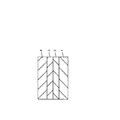
図1は、第1シミュレーションで想定した発光素子の構造を示す概略断面図である。厚さ5μmのn型GaN層1上に、多重量子井戸構造の活性層2が形成され、活性層2上に、p型Al0.15Ga0.85N層による厚さ20nmのp型クラッド層(電子ブロック層)3が形成され、p型クラッド層3上に、厚さ80nmのp型GaN層4が形成されている。第1実施例及び第1比較例によるGaN系半導体発光素子は、それぞれ、活性層2の構造が異なり、残りの構造は共通である。
FIG. 1 is a schematic cross-sectional view showing the structure of the light emitting element assumed in the first simulation. An
図2A及び図2Bは、それぞれ、第1比較例及び第1実施例によるGaN系半導体発光素子のコンダクションバンドの概略的なバンド図であり、活性層2の積層構造を示す。
2A and 2B are schematic band diagrams of a conduction band of a GaN-based semiconductor light emitting device according to the first comparative example and the first example, respectively, and show a stacked structure of the
積層構造のバリア層、例えば、InGaN層とGaN層との積層構造のバリア層を、InGaN/GaN層等と表記する。「/」の左方側に、n型半導体層側に配置される層を記す。 A barrier layer having a stacked structure, for example, a barrier layer having a stacked structure of an InGaN layer and a GaN layer is referred to as an InGaN / GaN layer. A layer arranged on the n-type semiconductor layer side is described on the left side of “/”.
第1比較例及び第1実施例の活性層2において共通に、10層のバリア層b1〜b10と、9層のウェル層w1〜w9とが、交互に積層されている。最もn型半導体層側のバリア層b1をファーストバリア層、最もp型半導体層側のバリア層b10をラストバリア層と呼び、中間のバリア層b2〜b9を、内部バリア層と呼ぶ。
In the
第1比較例による活性層2は、以下のようなものである。
The
バリア層・・・ ファーストバリア:GaN(厚さ5nm)
内部バリア:In0.03Ga0.97N/GaN(厚さ2nm/3nm)
ラストバリア:In0.03Ga0.97N/GaN(厚さ2nm/3nm)
バリア数:10
ウェル層・・・ In0.17Ga0.83N(厚さ3.5nm)
ウェル数:9
第1実施例による活性層2は、以下のようなものである。
Barrier layer: First barrier: GaN (thickness 5 nm)
Internal barrier: In 0.03 Ga 0.97 N / GaN (
Last barrier: In 0.03 Ga 0.97 N / GaN (
Number of barriers: 10
Well layer: In 0.17 Ga 0.83 N (thickness 3.5 nm)
Number of wells: 9
The
バリア層・・・ ファーストバリア:GaN/Al0.03Ga0.97N(厚さ3nm/2nm)
内部バリア:In0.03Ga0.97N/GaN(厚さ2nm/3nm)
ラストバリア:In0.03Ga0.97N/GaN(厚さ2nm/3nm)
バリア数:10
ウェル層・・・ In0.17Ga0.83N(厚さ3.5nm)
ウェル数:9
つまり、第1比較例はファーストバリア層b1がGaN層であり、第1実施例はファーストバリア層b1がGaN/AlGaN層である。
Barrier layer: First barrier: GaN / Al 0.03 Ga 0.97 N (
Internal barrier: In 0.03 Ga 0.97 N / GaN (
Last barrier: In 0.03 Ga 0.97 N / GaN (
Number of barriers: 10
Well layer: In 0.17 Ga 0.83 N (thickness 3.5 nm)
Number of wells: 9
That is, in the first comparative example, the first barrier layer b1 is a GaN layer, and in the first example, the first barrier layer b1 is a GaN / AlGaN layer.
なお、ウェル層に用いられるInxGa1−xN層のIn組成xは、バリア層に用いられるInyGa1−yN層のIn組成yに対し、バンドギャップが狭くなるように選ばれており、例えば0.10≦x≦0.25であり、0.01≦y≦0.05である。本シミュレーションでは一例として、x=0.17、y=0.03としている。 The In composition x of the In x Ga 1-x N layer used for the well layer is selected so that the band gap is narrower than the In composition y of the In y Ga 1-y N layer used for the barrier layer. For example, 0.10 ≦ x ≦ 0.25 and 0.01 ≦ y ≦ 0.05. In this simulation, as an example, x = 0.17 and y = 0.03.
シミュレーションには、STR社のバンドギャップモデリングシミュレーションソフトウェアであるSiLENSeを用い、歪み、分極、転位欠陥、オージェ効果等を考慮した計算を行った。電子移動度を200cm2/V.sとし、ホール移動度を5cm2/V.sとした。 In the simulation, SiLENSe, which is a band gap modeling simulation software manufactured by STR, was used, and calculations were performed in consideration of strain, polarization, dislocation defects, Auger effect, and the like. The electron mobility is 200 cm 2 / V. s, and the hole mobility is 5 cm 2 / V. s.
図3は、第1シミュレーションで得られた第1実施例及び第1比較例によるGaN系半導体発光素子のIQEの電流密度依存性を示すグラフである。第1実施例の結果を四角のプロットで示し、第1比較例の結果を菱形のプロットで示す。 FIG. 3 is a graph showing the current density dependence of IQE of the GaN-based semiconductor light emitting devices according to the first example and the first comparative example obtained in the first simulation. The results of the first example are shown by square plots, and the results of the first comparative example are shown by rhombus plots.
どちらのサンプルについても、IQEは、電流密度が0から増えると急激に大きくなり、最大値を取った後、電流密度増加に伴い緩やかに減少する傾向を示している。ファーストバリア層をGaNとした第1比較例に比べ、ファーストバリア層をGaN/AlGaNとした第1実施例は、調べた電流密度のほぼ全域に亘ってIQEがやや高くなる傾向が見られる。 In both samples, IQE increases rapidly when the current density increases from 0, and after taking the maximum value, shows a tendency to gradually decrease as the current density increases. Compared to the first comparative example in which the first barrier layer is GaN, in the first example in which the first barrier layer is GaN / AlGaN, IQE tends to be slightly higher over almost the entire current density examined.
第1実施例で第1比較例に比べIQEが向上した理由について考察する。なお、以下の考察は、上述のシミュレーション結果を解釈するための1つの考え方を示すものである。 The reason why IQE is improved in the first embodiment compared to the first comparative example will be considered. In addition, the following consideration shows one way of thinking for interpreting the above-described simulation result.
図4は、活性層のファーストバリア層をGaN/AlGaN層とした場合の影響を示した、コンダクションバンド及びバレンスバンドの概略的なバンド図である。ファーストバリア層BRをGaN単層とした場合、及びファーストバリア層BRをGaN/AlGaN層とした場合のバンド図を、それぞれ、実線及び破線で示す。 FIG. 4 is a schematic band diagram of a conduction band and a valence band, showing the effect when the first barrier layer of the active layer is a GaN / AlGaN layer. Band diagrams when the first barrier layer BR is a GaN single layer and when the first barrier layer BR is a GaN / AlGaN layer are shown by a solid line and a broken line, respectively.
ファーストバリア層BRにAlGaN層を形成したことにより、バンドギャップが広がり、ファーストバリア層のコンダクションバンドにおける電子に対するポテンシャル、及び、バレンスバンドのホールに対するポテンシャルが増加する。 By forming the AlGaN layer in the first barrier layer BR, the band gap is widened, and the potential for electrons in the conduction band of the first barrier layer and the potential for holes in the valence band are increased.
これにより、ファーストバリア層の電子に対するバリア性が向上し、n型半導体層側から活性層に流入する電子が減少すると考えられる。GaN系半導体素子では、電子に対しホールの移動度が遅く、電子がp型半導体層側にリークしやすい。n型半導体層側から活性層に流入する電子の減少により、電子のp型半導体層側へのリークが抑制されて、発光効率が向上するのではないかと推測される。 Thereby, it is considered that the barrier property against electrons of the first barrier layer is improved, and electrons flowing into the active layer from the n-type semiconductor layer side are reduced. In a GaN-based semiconductor element, the mobility of holes is slow with respect to electrons, and electrons are likely to leak to the p-type semiconductor layer side. It is presumed that the reduction of electrons flowing from the n-type semiconductor layer side into the active layer suppresses the leakage of electrons to the p-type semiconductor layer side, thereby improving the light emission efficiency.
また、ファーストバリア層のホールに対するバリア性が向上し、活性層からn型半導体層側にリークして非発光再結合するホールが減少して、発光効率が向上するのではないかと推測される。 In addition, it is estimated that the barrier property against holes in the first barrier layer is improved, and the number of holes that leak from the active layer to the n-type semiconductor layer and non-light-emitting recombination decreases, thereby improving the light emission efficiency.
なお、第1実施例の構造において、ラストバリア層側では、バリア層がInGaN/GaN層のままであり、ホールに対するポテンシャル増加が(ホールに対するバリア性の増加が)抑制されている。これにより、p型半導体層側から活性層に入るホールの流れの低減は抑制されている。 In the structure of the first embodiment, on the last barrier layer side, the barrier layer remains an InGaN / GaN layer, and an increase in potential with respect to holes (increase in barrier properties against holes) is suppressed. Thereby, the reduction of the flow of holes entering the active layer from the p-type semiconductor layer side is suppressed.
図5は、第1実施例の変形例によるGaN系半導体発光素子のコンダクションバンドの概略的なバンド図である。第1実施例との差は、活性層2の構造であり、本変形例は、ラストバリア層b10をInGaN層(例えば厚さ5nmのIn0.03Ga0.97N層)としている。
FIG. 5 is a schematic band diagram of a conduction band of a GaN-based semiconductor light emitting device according to a modification of the first embodiment. The difference from the first embodiment is the structure of the
ラストバリア層b10をInGaN/GaN層からInGaN層に変えることにより、ラストバリア層b10のバンドギャップが狭くなり、ホールに対するバリア性が減少する。これにより、p型半導体層側から活性層2に入るホールの流れの増加が図られ、さらなる発光効率向上が期待される。
By changing the last barrier layer b10 from the InGaN / GaN layer to the InGaN layer, the band gap of the last barrier layer b10 is narrowed, and the barrier property against holes is reduced. Thereby, the flow of holes entering the
なお、上述の実施例では、バリア層として、n型半導体層側にInGaN層を形成したInGaN/GaN層を用いた。以下、GaN系半導体発光素子の多重量子井戸構造の活性層における、GaNバリア層とInGaN/GaNバリア層との違いについて調べた第2シミュレーションについて説明する。 In the above-described embodiment, an InGaN / GaN layer in which an InGaN layer is formed on the n-type semiconductor layer side is used as the barrier layer. Hereinafter, a second simulation in which the difference between the GaN barrier layer and the InGaN / GaN barrier layer in the active layer having the multiple quantum well structure of the GaN-based semiconductor light-emitting device will be described.
第2シミュレーションでは、活性層のバリア層をGaN層とした第2比較例のGaN系半導体発光素子と、活性層のバリア層をIn0.03Ga0.97N/GaN層とした第3比較例のGaN系半導体発光素子とについて、シミュレーションを行った。第2比較例及び第3比較例とも、ウェル層はIn0.17Ga0.83N層とした。バリア層やウェル層の厚さや、層数等の条件は、第2比較例及び第3比較例で共通である。 In the second simulation, the GaN-based semiconductor light-emitting device of the second comparative example in which the barrier layer of the active layer is a GaN layer and the third comparison in which the barrier layer of the active layer is an In 0.03 Ga 0.97 N / GaN layer. A simulation was performed for the example GaN-based semiconductor light emitting device. In both the second comparative example and the third comparative example, the well layer was an In 0.17 Ga 0.83 N layer. Conditions such as the thickness of the barrier layer and the well layer and the number of layers are common to the second comparative example and the third comparative example.
シミュレーションには、STR社のバンドギャップモデリングシミュレーションソフトウェアであるSiLENSeを用い、歪み、分極、転位欠陥、オージェ効果等を考慮した計算を行った。 In the simulation, SiLENSe, which is a band gap modeling simulation software manufactured by STR, was used, and calculations were performed in consideration of strain, polarization, dislocation defects, Auger effect, and the like.
図6A及び図6Bは、それぞれ、第2シミュレーションで得られた第2比較例及び第3比較例の活性層におけるコンダクションバンドのバンド図及びバレンスバンドのバンド図である。バレンスバンドにおいて、バリア層をGaN層とした第2比較例に比べ、バリア層をInGaN/GaN層とした第3比較例の方が、バリア層のホールに対するポテンシャルのピークがやや低くなっていることわかる。これにより、InGaN/GaNバリア層の方が、GaNバリア層に比べて、例えば、ホールを活性層へ注入しやすくなる効果等があるものと期待される。 6A and 6B are a band diagram of a conduction band and a band diagram of a valence band in the active layers of the second comparative example and the third comparative example, respectively, obtained in the second simulation. In the valence band, the potential peak for the hole in the barrier layer is slightly lower in the third comparative example in which the barrier layer is an InGaN / GaN layer than in the second comparative example in which the barrier layer is a GaN layer. Recognize. Thereby, it is expected that the InGaN / GaN barrier layer has an effect of facilitating injection of holes into the active layer, for example, as compared with the GaN barrier layer.
なお、概略的なバンド図(例えば前述の図2A参照)を考える限りは、GaN層のバリア層のポテンシャルのピークと、InGaN/GaN層のバリア層のポテンシャルのピークとは、どちらもGaN層の部分でピークを取って一致するように思われる。しかし、第2シミュレーションを実施したところ、バレンスバンドにおいて、GaNバリア層よりも、InGaN/GaNバリア層の方が、ホールに対するポテンシャルのピークがやや低くなることがわかった。 As long as a schematic band diagram (for example, see FIG. 2A described above) is considered, the potential peak of the barrier layer of the GaN layer and the potential peak of the barrier layer of the InGaN / GaN layer are both in the GaN layer. It seems to match by taking a peak in the part. However, when the second simulation was performed, it was found that in the valence band, the InGaN / GaN barrier layer had a slightly lower potential peak for holes than the GaN barrier layer.
以上説明したように、GaN系半導体発光素子の多重量子井戸構造の活性層において、最もn型半導体層側のファーストバリア層をGaN/AlGaN層で形成し、ファーストバリア層よりもp型半導体層側のバリア層をInGaN/GaN層で形成することにより、発光効率の向上を図ることができる。また、最もp型半導体層側のラストバリア層をInGaN層とすることにより、さらなる発光効率向上が期待される。 As described above, in the active layer having the multiple quantum well structure of the GaN-based semiconductor light emitting device, the first barrier layer closest to the n-type semiconductor layer is formed of a GaN / AlGaN layer, and the p-type semiconductor layer side of the first barrier layer. The light emission efficiency can be improved by forming the barrier layer of InGaN / GaN layers. Further, when the last barrier layer closest to the p-type semiconductor layer is an InGaN layer, further improvement in luminous efficiency is expected.
以上実施例に沿って本発明を説明したが、本発明はこれらに制限されるものではない。例えば、種々の変更、改良、組み合わせ等が可能なことは当業者に自明であろう。 Although the present invention has been described with reference to the embodiments, the present invention is not limited thereto. It will be apparent to those skilled in the art that various modifications, improvements, combinations, and the like can be made.
1 n型GaN層
2 活性層
3 p型AlGaNクラッド層
4 p型GaN層
b1〜b10 バリア層
w2〜w9 ウェル層
1 n-
Claims (2)
前記n型半導体層上に形成され、GaN系半導体で形成され、バリア層とウェル層とが交互に複数層積層された多重量子井戸構造を有する活性層と、
前記活性層上に形成され、p型導電性を有するGaN系半導体で形成されたp型半導体層と
を有し、
前記活性層は、最もn型半導体層側の第1バリア層がGaN/AlGaN層で形成され、前記第1バリア層よりもp型半導体層側のバリア層がInGaN/GaN層で形成され、ウェル層が、前記InGaN/GaN層のバリア層のInGaN層よりもバンドギャップの狭いInGaN層で形成されているGaN系半導体発光素子。 an n-type semiconductor layer formed of a GaN-based semiconductor having n-type conductivity;
An active layer formed on the n-type semiconductor layer, formed of a GaN-based semiconductor, and having a multiple quantum well structure in which a plurality of barrier layers and well layers are alternately stacked;
A p-type semiconductor layer formed on the active layer and formed of a GaN-based semiconductor having p-type conductivity;
The active layer has a first barrier layer closest to the n-type semiconductor layer formed of a GaN / AlGaN layer, a barrier layer closer to the p-type semiconductor layer than the first barrier layer formed of an InGaN / GaN layer, A GaN-based semiconductor light emitting device, wherein the layer is formed of an InGaN layer having a narrower band gap than the InGaN layer of the barrier layer of the InGaN / GaN layer.
Priority Applications (2)
| Application Number | Priority Date | Filing Date | Title |
|---|---|---|---|
| JP2012010809A JP2013149889A (en) | 2012-01-23 | 2012-01-23 | GaN-BASED SEMICONDUCTOR LIGHT-EMITTING ELEMENT |
| US13/743,961 US8816320B2 (en) | 2012-01-23 | 2013-01-17 | GaN-containing semiconductor light emitting device |
Applications Claiming Priority (1)
| Application Number | Priority Date | Filing Date | Title |
|---|---|---|---|
| JP2012010809A JP2013149889A (en) | 2012-01-23 | 2012-01-23 | GaN-BASED SEMICONDUCTOR LIGHT-EMITTING ELEMENT |
Publications (1)
| Publication Number | Publication Date |
|---|---|
| JP2013149889A true JP2013149889A (en) | 2013-08-01 |
Family
ID=49047088
Family Applications (1)
| Application Number | Title | Priority Date | Filing Date |
|---|---|---|---|
| JP2012010809A Pending JP2013149889A (en) | 2012-01-23 | 2012-01-23 | GaN-BASED SEMICONDUCTOR LIGHT-EMITTING ELEMENT |
Country Status (1)
| Country | Link |
|---|---|
| JP (1) | JP2013149889A (en) |
Cited By (8)
| Publication number | Priority date | Publication date | Assignee | Title |
|---|---|---|---|---|
| CN105895768A (en) * | 2016-06-16 | 2016-08-24 | 厦门乾照光电股份有限公司 | Well-doped light emitting diode |
| JP2018037660A (en) * | 2016-09-01 | 2018-03-08 | エルジー イノテック カンパニー リミテッド | Semiconductor device and semiconductor device package including the same |
| CN110137326A (en) * | 2019-05-22 | 2019-08-16 | 佛山市国星半导体技术有限公司 | A kind of epitaxial structure and preparation method thereof that luminous efficacy can be promoted under low current density |
| US10593838B2 (en) | 2017-08-14 | 2020-03-17 | Lg Innotek Co., Ltd. | Semiconductor device |
| US10734552B2 (en) | 2016-06-20 | 2020-08-04 | Lg Innotek Co., Ltd. | Semiconductor device having a light emitting structure |
| US10903395B2 (en) | 2016-11-24 | 2021-01-26 | Lg Innotek Co., Ltd. | Semiconductor device having varying concentrations of aluminum |
| US10910519B2 (en) | 2016-09-13 | 2021-02-02 | Lg Innotek Co., Ltd. | Semiconductor device having layers including aluminum and semiconductor device package including same |
| US11569416B2 (en) | 2016-09-10 | 2023-01-31 | Suzhou Lekin Semiconductor Co., Ltd. | Light emitting semiconductor device |
Citations (7)
| Publication number | Priority date | Publication date | Assignee | Title |
|---|---|---|---|---|
| JP2001223441A (en) * | 2000-02-08 | 2001-08-17 | Samsung Electronics Co Ltd | Nitride semiconductor light emitting device |
| JP2004087908A (en) * | 2002-08-28 | 2004-03-18 | Sharp Corp | Nitride semiconductor light-emitting element, method for manufacturing the same, and optical device mounting the same |
| JP2005020396A (en) * | 2003-06-26 | 2005-01-20 | Toshiba Lighting & Technology Corp | Broadcasting equipment remote monitor system |
| JP2005268743A (en) * | 2004-02-17 | 2005-09-29 | Sumitomo Electric Ind Ltd | Semiconductor device having quantum well structure, and forming method of semiconductor device |
| JP2007150312A (en) * | 2005-11-25 | 2007-06-14 | Sharp Corp | Semiconductor light-emitting device and method of fabricating the same |
| JP2009152552A (en) * | 2007-12-18 | 2009-07-09 | Seoul Opto Devices Co Ltd | Light-emitting diode having active region of multiple quantum well structure |
| JP2009259885A (en) * | 2008-04-14 | 2009-11-05 | Sony Corp | Gan-based semiconductor light-emitting element, light-emitting element assembly, light-emitting device, method of driving gan-based semiconductor light-emitting element, and image display apparatus |
-
2012
- 2012-01-23 JP JP2012010809A patent/JP2013149889A/en active Pending
Patent Citations (7)
| Publication number | Priority date | Publication date | Assignee | Title |
|---|---|---|---|---|
| JP2001223441A (en) * | 2000-02-08 | 2001-08-17 | Samsung Electronics Co Ltd | Nitride semiconductor light emitting device |
| JP2004087908A (en) * | 2002-08-28 | 2004-03-18 | Sharp Corp | Nitride semiconductor light-emitting element, method for manufacturing the same, and optical device mounting the same |
| JP2005020396A (en) * | 2003-06-26 | 2005-01-20 | Toshiba Lighting & Technology Corp | Broadcasting equipment remote monitor system |
| JP2005268743A (en) * | 2004-02-17 | 2005-09-29 | Sumitomo Electric Ind Ltd | Semiconductor device having quantum well structure, and forming method of semiconductor device |
| JP2007150312A (en) * | 2005-11-25 | 2007-06-14 | Sharp Corp | Semiconductor light-emitting device and method of fabricating the same |
| JP2009152552A (en) * | 2007-12-18 | 2009-07-09 | Seoul Opto Devices Co Ltd | Light-emitting diode having active region of multiple quantum well structure |
| JP2009259885A (en) * | 2008-04-14 | 2009-11-05 | Sony Corp | Gan-based semiconductor light-emitting element, light-emitting element assembly, light-emitting device, method of driving gan-based semiconductor light-emitting element, and image display apparatus |
Cited By (11)
| Publication number | Priority date | Publication date | Assignee | Title |
|---|---|---|---|---|
| CN105895768A (en) * | 2016-06-16 | 2016-08-24 | 厦门乾照光电股份有限公司 | Well-doped light emitting diode |
| US10734552B2 (en) | 2016-06-20 | 2020-08-04 | Lg Innotek Co., Ltd. | Semiconductor device having a light emitting structure |
| JP2018037660A (en) * | 2016-09-01 | 2018-03-08 | エルジー イノテック カンパニー リミテッド | Semiconductor device and semiconductor device package including the same |
| US10340415B2 (en) | 2016-09-01 | 2019-07-02 | Lg Innotek Co., Ltd. | Semiconductor device and semiconductor device package including the same |
| US10937923B2 (en) | 2016-09-01 | 2021-03-02 | Lg Innotek Co., Ltd. | Semiconductor device and semiconductor device package including the same |
| US11569416B2 (en) | 2016-09-10 | 2023-01-31 | Suzhou Lekin Semiconductor Co., Ltd. | Light emitting semiconductor device |
| US11961943B2 (en) | 2016-09-10 | 2024-04-16 | Suzhou Lekin Semiconductor Co., Ltd. | Light emitting semiconductor device for enhancing light extraction efficiency |
| US10910519B2 (en) | 2016-09-13 | 2021-02-02 | Lg Innotek Co., Ltd. | Semiconductor device having layers including aluminum and semiconductor device package including same |
| US10903395B2 (en) | 2016-11-24 | 2021-01-26 | Lg Innotek Co., Ltd. | Semiconductor device having varying concentrations of aluminum |
| US10593838B2 (en) | 2017-08-14 | 2020-03-17 | Lg Innotek Co., Ltd. | Semiconductor device |
| CN110137326A (en) * | 2019-05-22 | 2019-08-16 | 佛山市国星半导体技术有限公司 | A kind of epitaxial structure and preparation method thereof that luminous efficacy can be promoted under low current density |
Similar Documents
| Publication | Publication Date | Title |
|---|---|---|
| JP2013149889A (en) | GaN-BASED SEMICONDUCTOR LIGHT-EMITTING ELEMENT | |
| JP5737111B2 (en) | Group III nitride semiconductor light emitting device | |
| JP2012015535A5 (en) | ||
| GB2543682A (en) | Epitaxial structure for improving efficiency drop of GaN-based LED | |
| KR101228983B1 (en) | Nitride Semiconductor Light Emitting Device | |
| WO2012089003A1 (en) | Nitride light emitting diode with compound current spreading layer | |
| JP2009071220A (en) | Group iii nitride compound semiconductor light emitting element | |
| JP2009260398A5 (en) | ||
| TWI502767B (en) | Semiconductor light emitting structure | |
| US20200075800A1 (en) | Light-emitting diode | |
| JP2015511407A5 (en) | ||
| JP4960465B2 (en) | Semiconductor light emitting device | |
| KR101423720B1 (en) | Light emitting device having active region of multi quantum well structure and method for fabricating the same | |
| US8816320B2 (en) | GaN-containing semiconductor light emitting device | |
| KR20100070250A (en) | Nitride semiconductor light emitting device | |
| JP5912564B2 (en) | GaN-based semiconductor light emitting device | |
| JP2014022736A (en) | Multiquantum well structure and light emitting diode having the same | |
| JP2019517133A (en) | Light emitting diode comprising at least one wide band gap interlayer arranged in at least one barrier layer of the light emitting region | |
| US20130228740A1 (en) | Light-emitting diode device | |
| US9087946B2 (en) | Light emitting device | |
| Zhao et al. | Enhanced performance of GaN-based light-emitting diodes with composite electron blocking layer | |
| JP5460754B2 (en) | Semiconductor light emitting device | |
| JP2012069982A (en) | Nitride semiconductor light-emitting element | |
| CN109671825B (en) | Polar semiconductor light-emitting diode | |
| JP2013191617A (en) | Semiconductor light-emitting element |
Legal Events
| Date | Code | Title | Description |
|---|---|---|---|
| A621 | Written request for application examination |
Free format text: JAPANESE INTERMEDIATE CODE: A621 Effective date: 20150107 |
|
| A977 | Report on retrieval |
Free format text: JAPANESE INTERMEDIATE CODE: A971007 Effective date: 20151021 |
|
| A131 | Notification of reasons for refusal |
Free format text: JAPANESE INTERMEDIATE CODE: A131 Effective date: 20151110 |
|
| A521 | Written amendment |
Free format text: JAPANESE INTERMEDIATE CODE: A523 Effective date: 20160108 |
|
| A02 | Decision of refusal |
Free format text: JAPANESE INTERMEDIATE CODE: A02 Effective date: 20160315 |