JP2013145021A - Rotating device - Google Patents
Rotating device Download PDFInfo
- Publication number
- JP2013145021A JP2013145021A JP2012006024A JP2012006024A JP2013145021A JP 2013145021 A JP2013145021 A JP 2013145021A JP 2012006024 A JP2012006024 A JP 2012006024A JP 2012006024 A JP2012006024 A JP 2012006024A JP 2013145021 A JP2013145021 A JP 2013145021A
- Authority
- JP
- Japan
- Prior art keywords
- band
- dynamic pressure
- groove
- shaped region
- region
- Prior art date
- Legal status (The legal status is an assumption and is not a legal conclusion. Google has not performed a legal analysis and makes no representation as to the accuracy of the status listed.)
- Pending
Links
Images


Classifications
-
- H—ELECTRICITY
- H02—GENERATION; CONVERSION OR DISTRIBUTION OF ELECTRIC POWER
- H02K—DYNAMO-ELECTRIC MACHINES
- H02K7/00—Arrangements for handling mechanical energy structurally associated with dynamo-electric machines, e.g. structural association with mechanical driving motors or auxiliary dynamo-electric machines
- H02K7/08—Structural association with bearings
- H02K7/086—Structural association with bearings radially supporting the rotor around a fixed spindle; radially supporting the rotor directly
-
- H—ELECTRICITY
- H02—GENERATION; CONVERSION OR DISTRIBUTION OF ELECTRIC POWER
- H02K—DYNAMO-ELECTRIC MACHINES
- H02K5/00—Casings; Enclosures; Supports
- H02K5/04—Casings or enclosures characterised by the shape, form or construction thereof
- H02K5/16—Means for supporting bearings, e.g. insulating supports or means for fitting bearings in the bearing-shields
- H02K5/167—Means for supporting bearings, e.g. insulating supports or means for fitting bearings in the bearing-shields using sliding-contact or spherical cap bearings
- H02K5/1675—Means for supporting bearings, e.g. insulating supports or means for fitting bearings in the bearing-shields using sliding-contact or spherical cap bearings radially supporting the rotary shaft at only one end of the rotor
-
- F—MECHANICAL ENGINEERING; LIGHTING; HEATING; WEAPONS; BLASTING
- F16—ENGINEERING ELEMENTS AND UNITS; GENERAL MEASURES FOR PRODUCING AND MAINTAINING EFFECTIVE FUNCTIONING OF MACHINES OR INSTALLATIONS; THERMAL INSULATION IN GENERAL
- F16C—SHAFTS; FLEXIBLE SHAFTS; ELEMENTS OR CRANKSHAFT MECHANISMS; ROTARY BODIES OTHER THAN GEARING ELEMENTS; BEARINGS
- F16C17/00—Sliding-contact bearings for exclusively rotary movement
- F16C17/02—Sliding-contact bearings for exclusively rotary movement for radial load only
- F16C17/026—Sliding-contact bearings for exclusively rotary movement for radial load only with helical grooves in the bearing surface to generate hydrodynamic pressure, e.g. herringbone grooves
-
- F—MECHANICAL ENGINEERING; LIGHTING; HEATING; WEAPONS; BLASTING
- F16—ENGINEERING ELEMENTS AND UNITS; GENERAL MEASURES FOR PRODUCING AND MAINTAINING EFFECTIVE FUNCTIONING OF MACHINES OR INSTALLATIONS; THERMAL INSULATION IN GENERAL
- F16C—SHAFTS; FLEXIBLE SHAFTS; ELEMENTS OR CRANKSHAFT MECHANISMS; ROTARY BODIES OTHER THAN GEARING ELEMENTS; BEARINGS
- F16C33/00—Parts of bearings; Special methods for making bearings or parts thereof
- F16C33/02—Parts of sliding-contact bearings
- F16C33/04—Brasses; Bushes; Linings
- F16C33/06—Sliding surface mainly made of metal
- F16C33/10—Construction relative to lubrication
- F16C33/1025—Construction relative to lubrication with liquid, e.g. oil, as lubricant
- F16C33/106—Details of distribution or circulation inside the bearings, e.g. details of the bearing surfaces to affect flow or pressure of the liquid
- F16C33/107—Grooves for generating pressure
-
- H—ELECTRICITY
- H02—GENERATION; CONVERSION OR DISTRIBUTION OF ELECTRIC POWER
- H02K—DYNAMO-ELECTRIC MACHINES
- H02K7/00—Arrangements for handling mechanical energy structurally associated with dynamo-electric machines, e.g. structural association with mechanical driving motors or auxiliary dynamo-electric machines
- H02K7/08—Structural association with bearings
- H02K7/085—Structural association with bearings radially supporting the rotary shaft at only one end of the rotor
-
- F—MECHANICAL ENGINEERING; LIGHTING; HEATING; WEAPONS; BLASTING
- F16—ENGINEERING ELEMENTS AND UNITS; GENERAL MEASURES FOR PRODUCING AND MAINTAINING EFFECTIVE FUNCTIONING OF MACHINES OR INSTALLATIONS; THERMAL INSULATION IN GENERAL
- F16C—SHAFTS; FLEXIBLE SHAFTS; ELEMENTS OR CRANKSHAFT MECHANISMS; ROTARY BODIES OTHER THAN GEARING ELEMENTS; BEARINGS
- F16C2240/00—Specified values or numerical ranges of parameters; Relations between them
- F16C2240/30—Angles, e.g. inclinations
-
- F—MECHANICAL ENGINEERING; LIGHTING; HEATING; WEAPONS; BLASTING
- F16—ENGINEERING ELEMENTS AND UNITS; GENERAL MEASURES FOR PRODUCING AND MAINTAINING EFFECTIVE FUNCTIONING OF MACHINES OR INSTALLATIONS; THERMAL INSULATION IN GENERAL
- F16C—SHAFTS; FLEXIBLE SHAFTS; ELEMENTS OR CRANKSHAFT MECHANISMS; ROTARY BODIES OTHER THAN GEARING ELEMENTS; BEARINGS
- F16C2240/00—Specified values or numerical ranges of parameters; Relations between them
- F16C2240/40—Linear dimensions, e.g. length, radius, thickness, gap
- F16C2240/42—Groove sizes
-
- F—MECHANICAL ENGINEERING; LIGHTING; HEATING; WEAPONS; BLASTING
- F16—ENGINEERING ELEMENTS AND UNITS; GENERAL MEASURES FOR PRODUCING AND MAINTAINING EFFECTIVE FUNCTIONING OF MACHINES OR INSTALLATIONS; THERMAL INSULATION IN GENERAL
- F16C—SHAFTS; FLEXIBLE SHAFTS; ELEMENTS OR CRANKSHAFT MECHANISMS; ROTARY BODIES OTHER THAN GEARING ELEMENTS; BEARINGS
- F16C2240/00—Specified values or numerical ranges of parameters; Relations between them
- F16C2240/40—Linear dimensions, e.g. length, radius, thickness, gap
- F16C2240/70—Diameters; Radii
Landscapes
- Engineering & Computer Science (AREA)
- General Engineering & Computer Science (AREA)
- Power Engineering (AREA)
- Mechanical Engineering (AREA)
- Physics & Mathematics (AREA)
- Fluid Mechanics (AREA)
- Chemical & Material Sciences (AREA)
- Oil, Petroleum & Natural Gas (AREA)
- Sliding-Contact Bearings (AREA)
- Motor Or Generator Frames (AREA)
- Connection Of Motors, Electrical Generators, Mechanical Devices, And The Like (AREA)
Abstract
Description
本発明は、回転体を潤滑剤を介して回転自在に支持する固定体を備える回転機器に関する。 The present invention relates to a rotating device including a fixed body that rotatably supports a rotating body via a lubricant.
ハードディスクドライブなどのディスク駆動装置は、小型化、大容量化が進み、種々の電子機器に搭載されている。特にノートパソコンや携帯型音楽再生機器などの携帯型の電子機器へのディスク駆動装置の搭載が進んでいる。 Disk drive devices such as hard disk drives are becoming smaller and larger in capacity, and are mounted on various electronic devices. In particular, the mounting of disk drive devices in portable electronic devices such as notebook computers and portable music playback devices is advancing.
ディスク駆動装置の軸受として流体動圧軸受(Fluid Dynamic Bearing)が知られている。この流体動圧軸受では、回転体と固定体との隙間に潤滑剤が注入され、回転体が固定体に対して回転するときに潤滑剤に生じる動圧によって回転体と固定体との非接触状態が維持される(例えば、特許文献1、2参照)。
A fluid dynamic bearing is known as a disk drive bearing. In this fluid dynamic pressure bearing, the lubricant is injected into the gap between the rotating body and the fixed body, and the rotating body and the fixed body are not in contact with each other due to the dynamic pressure generated in the lubricant when the rotating body rotates relative to the fixed body. The state is maintained (see, for example,
ディスクに対するヘッドの位置がずれるとリード/ライトエラーが生じうるので、ディスク駆動装置では耐衝撃性を高めることが重要である。特に携帯型の電子機器に搭載されるディスク駆動装置に対しては、デスクトップPC(Personal Computer)などの据置型の電子機器に搭載されるものと比べて、落下などの衝撃にも耐えうるように耐衝撃性のさらなる向上が求められている。 If the position of the head with respect to the disk is deviated, read / write errors may occur, so it is important to improve impact resistance in the disk drive device. In particular, disk drive units mounted on portable electronic devices can withstand impacts such as dropping compared to those mounted on stationary electronic devices such as desktop PCs (Personal Computers). There is a need for further improvement in impact resistance.
流体動圧軸受を採用するディスク駆動装置の耐衝撃性を高めるためのひとつの手法は、ラジアル動圧を高めてラジアル剛性を強化することである。しかしながら一般に、ラジアル動圧を高めると、その分消費電力も増大する。特に携帯型の電子機器はバッテリ駆動であることが多いから、そのように消費電力の大きなディスク駆動装置を搭載すると、使用可能時間が短くなりうる。 One technique for increasing the impact resistance of a disk drive device that employs a fluid dynamic bearing is to increase the radial dynamic pressure and strengthen the radial rigidity. However, generally, when the radial dynamic pressure is increased, the power consumption is increased accordingly. In particular, since portable electronic devices are often battery-driven, if a disk drive device with such a large power consumption is mounted, the usable time can be shortened.
また、耐衝撃性の向上と消費電力の低減とが相反しうるという課題は携帯型の電子機器に搭載されるディスク駆動装置に限らず、任意の回転機器でも起こりうる。 Further, the problem that the improvement in impact resistance and the reduction in power consumption may conflict with each other is not limited to the disk drive device mounted on the portable electronic device, and may occur in any rotating device.
本発明はこうした状況に鑑みてなされたものであり、その目的は耐衝撃性を向上しつつ、それによる消費電力の増大を抑えることができる回転機器の提供にある。 The present invention has been made in view of such circumstances, and an object thereof is to provide a rotating device capable of improving impact resistance while suppressing an increase in power consumption.
本発明のある態様は、回転機器に関する。この回転機器は、回転体を潤滑剤を介して回転自在に支持する固定体を備える回転機器であって、潤滑剤が充填される隙間を形成する回転体の面および固定体の面のうちのいずれか一方には、回転体の回転軸を環囲すると共に回転体が回転するとき潤滑剤に動圧を生成する帯状の領域が形成され、帯状の領域には、帯状の領域を横切る方向に沿って帯状の領域の両側から複数の溝が形成され、帯状の領域の一方の側から形成される溝は帯状の領域の他方の側に近いほど浅く且つ狭くなるよう形成され、帯状の領域の他方の側から形成される溝は帯状の領域の一方の側に近いほど浅く且つ狭くなるよう形成される。 One embodiment of the present invention relates to a rotating device. This rotating device is a rotating device including a fixed body that rotatably supports the rotating body via a lubricant, and includes a surface of the rotating body that forms a gap filled with a lubricant and a surface of the fixed body. Either one is formed with a band-like region that surrounds the rotation axis of the rotating body and generates dynamic pressure in the lubricant when the rotating body rotates. The band-shaped region extends in a direction crossing the band-shaped region. A plurality of grooves are formed from both sides of the band-shaped region along the groove, and the groove formed from one side of the band-shaped region is formed so as to be shallower and narrower as the other side of the band-shaped region is closer. The groove formed from the other side is formed so as to become shallower and narrower as it is closer to one side of the band-like region.
この態様によると、効率良く動圧を生成できる。 According to this aspect, dynamic pressure can be generated efficiently.
本発明の別の態様もまた、回転機器である。この回転機器は、回転体を潤滑剤を介して回転自在に支持する固定体を備える回転機器であって、潤滑剤が充填される隙間を形成する回転体の面および固定体の面のうちのいずれか一方には、回転体の回転軸を環囲すると共に回転体が回転するとき潤滑剤に動圧を生成する帯状の領域が形成され、帯状の領域には、帯状の領域を横切る方向に沿って帯状の領域の一方の側から他方の側に向かって複数の溝が形成され、帯状の領域の一方の側から形成される溝は帯状の領域の他方の側に近いほど浅く且つ狭くなるよう形成される。 Another embodiment of the present invention is also a rotating device. This rotating device is a rotating device including a fixed body that rotatably supports the rotating body via a lubricant, and includes a surface of the rotating body that forms a gap filled with a lubricant and a surface of the fixed body. Either one is formed with a band-like region that surrounds the rotation axis of the rotating body and generates dynamic pressure in the lubricant when the rotating body rotates. The band-shaped region extends in a direction crossing the band-shaped region. A plurality of grooves are formed from one side of the band-shaped region to the other side, and the groove formed from one side of the band-shaped region becomes shallower and narrower as it is closer to the other side of the band-shaped region. Formed.
なお、以上の構成要素の任意の組み合わせや、本発明の構成要素や表現を方法、装置、システムなどの間で相互に置換したものもまた、本発明の態様として有効である。 Note that any combination of the above-described constituent elements, and those obtained by replacing the constituent elements and expressions of the present invention with each other among methods, apparatuses, systems, etc. are also effective as an aspect of the present invention.
本発明によれば、回転機器の耐衝撃性を向上しつつ、それによる消費電力の増大を抑えることができる。 ADVANTAGE OF THE INVENTION According to this invention, the increase in power consumption by it can be suppressed, improving the impact resistance of rotary equipment.
以下、各図面に示される同一または同等の構成要素、部材には、同一の符号を付するものとし、適宜重複した説明は省略する。また、各図面における部材の寸法は、理解を容易にするために適宜拡大、縮小して示される。また、各図面において実施の形態を説明する上で重要ではない部材の一部は省略して表示する。 Hereinafter, the same or equivalent components and members shown in the respective drawings are denoted by the same reference numerals, and repeated descriptions thereof are omitted as appropriate. In addition, the dimensions of the members in each drawing are appropriately enlarged or reduced for easy understanding. Also, in the drawings, some of the members that are not important for describing the embodiment are omitted.
実施の形態に係る回転機器は軸受として流体動圧軸受を採用する。回転機器は、回転体と、回転体を潤滑剤を介して回転自在に支持する固定体と、を備える。回転機器の回転時に潤滑剤に動圧を発生させる動圧溝は、端から中央に向けて先細りとなるよう形成される。これにより、より効率よく動圧を発生できる。 The rotary device according to the embodiment employs a fluid dynamic pressure bearing as a bearing. The rotating device includes a rotating body and a fixed body that rotatably supports the rotating body via a lubricant. A dynamic pressure groove that generates dynamic pressure in the lubricant during rotation of the rotating device is formed so as to taper from the end toward the center. Thereby, dynamic pressure can be generated more efficiently.
図1(a)、(b)は、実施の形態に係る回転機器1を示す上面図および側面図である。図1(a)は、回転機器1の上面図である。図1(a)では、回転機器1の内側の構成を示すため、トップカバー2を外した状態が示される。回転機器1は、ベース4と、回転体6と、磁気記録ディスク8と、データリード/ライト部10と、トップカバー2と、を備える。
以降ベース4に対して回転体6が搭載される側を上側として説明する。
1A and 1B are a top view and a side view showing a
Hereinafter, the side on which the
磁気記録ディスク8は、直径が95mmのガラス製の3.5インチ型磁気記録ディスクであり、その中央の孔の直径は25mm、厚みは1.27mmである。回転機器1はそのような磁気記録ディスク8を2枚搭載している。
各磁気記録ディスク8は、回転体6に載置され、回転体6の回転に伴って回転する。回転体6は、図1(a)では図示しない軸受ユニット12を介してベース4に対して回転可能に取り付けられる。
The
Each
ベース4は、回転機器1の底部を形成する底板部4aと、磁気記録ディスク8の載置領域を囲むように底板部4aの外周に沿って形成された外周壁部4bと、を有する。外周壁部4bの上面4cには、6つのねじ穴22が設けられる。
The
データリード/ライト部10は、記録再生ヘッド(不図示)と、スイングアーム14と、ボイスコイルモータ16と、ピボットアセンブリ18と、を含む。記録再生ヘッドは、スイングアーム14の先端部に取り付けられ、磁気記録ディスク8にデータを記録し、磁気記録ディスク8からデータを読み取る。ピボットアセンブリ18は、スイングアーム14をベース4に対してヘッド回転軸Sの周りに揺動自在に支持する。ボイスコイルモータ16は、スイングアーム14をヘッド回転軸Sの周りに揺動させ、記録再生ヘッドを磁気記録ディスク8の上面上の所望の位置に移動させる。ボイスコイルモータ16およびピボットアセンブリ18は、ヘッドの位置を制御する公知の技術を用いて構成される。
The data read / write
図1(b)は回転機器1の側面図である。トップカバー2は、6つのねじ20を用いてベース4の外周壁部4bの上面4cに固定される。6つのねじ20は、6つのねじ穴22にそれぞれ対応する。特にトップカバー2と外周壁部4bの上面4cとは、それらの接合部分から回転機器1の内側へリークが生じないように互いに固定される。
FIG. 1B is a side view of the
図2は、図1(a)のA−A線断面図である。回転体6は、シャフト26と、ハブ28と、フランジ30と、円筒状マグネット32と、クランパ36と、を含む。ハブ28のディスク載置面28a上に磁気記録ディスク8が載置される。シャフト26の上端面にはディスク固定用ねじ穴26aが設けられている。クランパ36は、ディスク固定用ねじ穴26aに螺合されるディスク固定用ねじ38によってハブ28の上面28bに圧着されると共に、2枚の磁気記録ディスク8のうちの上側の磁気記録ディスク8をスペーサ37に押しつける。スペーサ37は下側の磁気記録ディスク8をハブ28のディスク載置面28aに押しつける。
FIG. 2 is a cross-sectional view taken along line AA in FIG. The
ハブ28は、軟磁性を有する例えばSUS430F等の鉄鋼材料から形成される。ハブ28は、鉄鋼板を例えばプレス加工や切削加工することにより形成され、略カップ状の所定の形状に形成される。ハブ28の鉄鋼材料としては、例えば、大同特殊鋼株式会社が供給する商品名DHS1のステンレスはアウトガスが少なく、加工容易である点で好ましい。また、同様に同社が供給する商品名DHS2のステンレスはさらに耐食性が良好な点でより好ましい。
The
シャフト26は、ハブ28の中心に設けられた孔28cであって回転体6の回転軸Rと同軸に設けられた孔28cに圧入と接着とを併用した状態で固着される。フランジ30は円環形状を有し、フランジ30の断面は逆L字形状を有する。フランジ30は、ハブ28の下垂部28dの内周面28eに接着により固定される。
The
円筒状マグネット32は、ハブ28の内側の円筒面に相当する円筒状内周面28fに接着固定される。円筒状マグネット32は、ネオジウム、鉄、ホウ素などの希土類材料によって形成され、積層コア40の12本の突極と半径方向に対向する。円筒状マグネット32にはその周方向(回転軸Rを中心とし回転軸Rに垂直な円の接線方向)に16極の駆動用着磁が施される。円筒状マグネット32の表面には電着塗装やスプレー塗装などによる防錆処理が施される。
The
ベース4、積層コア40、コイル42、ハウジング44およびスリーブ46は回転機器1の固定体を構成する。積層コア40は円環部とそこから半径方向(すなわち回転軸Rに直交する方向)外向きに伸びる12本の突極とを有し、ベース4の上面4d側に固定される。積層コア40は、7枚の薄型電磁鋼板を積層しカシメにより一体化して形成される。積層コア40の表面には電着塗装や粉体塗装などによる絶縁塗装が施される。それぞれの突極にはコイル42が巻回される。このコイル42に3相の略正弦波状の駆動電流が流れることにより突極に沿って駆動磁束が発生する。ベース4の上面4dには、回転体6の回転軸Rを中心とする円環状の環状壁部4eが設けられる。積層コア40は環状壁部4eの外周面4gに圧入されもしくは隙間ばめによって接着固定される。
The
ベース4には、回転体6の回転軸Rを中心とする貫通孔4hが設けられる。軸受ユニット12は、ハウジング44と、スリーブ46と、を含み、回転体6をベース4に対して回転自在に支持する。ハウジング44はベース4の貫通孔4hに接着により固定される。ハウジング44は、円筒部と底部とが一体に形成された有底カップ形状を有し、その底部を下にしてベース4に対して接着固定される。
The
スリーブ46は、ハウジング44の内側の側面に接着により固定される円筒状の部材である。スリーブ46の上端には半径方向外向きに張り出した張出部46aが形成されている。この張出部46aは、フランジ30と協働して回転体6の軸方向すなわち回転軸方向の移動を制限する。
スリーブ46にはシャフト26が収まる。シャフト26およびハブ28およびフランジ30を含む回転体6の一部と軸受ユニット12との隙間には潤滑剤48が充填される。
The
The
スリーブ46の内周面46bには、互いに上下に離間した第1ラジアル動圧溝形成領域54と第2ラジアル動圧溝形成領域56とが形成される。第1ラジアル動圧溝形成領域54、第2ラジアル動圧溝形成領域56のいずれにもラジアル動圧溝が形成される。第1ラジアル動圧溝形成領域54は回転軸Rを環囲する帯状の領域であり、回転軸Rと略平行となるよう形成される。すなわち、第1ラジアル動圧溝形成領域54は回転軸Rを中心とした円筒状の領域である。したがって、第1ラジアル動圧溝形成領域54が延在する方向は周方向である。第2ラジアル動圧溝形成領域56についても同様である。
回転体6が回転するとき、第1ラジアル動圧溝形成領域54および第2ラジアル動圧溝形成領域56に形成されたラジアル動圧溝が潤滑剤48に生成する動圧によって、回転体6は半径方向に固定体と非接触に支持される。
A first radial dynamic pressure
When the
ハウジング44の上面に対向するフランジ30の下面には、第1スラスト動圧溝形成領域58が形成される。張出部46aの下面に対向するフランジ30の上面には、第2スラスト動圧溝形成領域60が形成される。第1スラスト動圧溝形成領域58、第2スラスト動圧溝形成領域60のいずれにもスラスト動圧溝が形成される。第1スラスト動圧溝形成領域58は回転軸Rを環囲する帯状の領域であり、軸方向と略直交するよう形成される。すなわち、第1スラスト動圧溝形成領域58は回転軸Rを中心とした円板状の領域である。したがって、第1スラスト動圧溝形成領域58が延在する方向は周方向である。第2スラスト動圧溝形成領域60についても同様である。
回転体6が回転するとき、第1スラスト動圧溝形成領域58および第2スラスト動圧溝形成領域60に形成されたスラスト動圧溝が潤滑剤48に生成する動圧によって、回転体6は軸方向に固定体と非接触に支持される。
A first thrust dynamic pressure
When the
なお、第1ラジアル動圧溝形成領域54および第2ラジアル動圧溝形成領域56のうちの少なくとも一方を、スリーブ46の内周面46bの代わりにシャフト26の外周面26bに形成してもよい。また、第1スラスト動圧溝形成領域58をハウジング44の上面に形成してもよく、第2スラスト動圧溝形成領域60を張出部46aの下面に形成してもよい。
Note that at least one of the first radial dynamic pressure
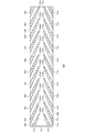
図3は、第1ラジアル動圧溝形成領域54の展開図である。第1ラジアル動圧溝形成領域54のラジアル動圧溝は、周方向A1に規則的に配列されると共に、第1ラジアル動圧溝形成領域54を上下に略2等分する中央線68に対して略対称となるよう形成される。特に、第1ラジアル動圧溝形成領域54には略同一形状のラジアル動圧溝が略等間隔に配置され、かつ、第1ラジアル動圧溝形成領域54は中央線68を対称軸とする線対称性を有する。第1ラジアル動圧溝形成領域54は中央線68を境に上側形成領域70と下側形成領域72とに分割される。上側形成領域70の幅L1と下側形成領域72の幅L2とは略等しい。
FIG. 3 is a development view of the first radial dynamic pressure
上側形成領域70には、第1ラジアル動圧溝形成領域54の上側の縁62から中央線68に向けて10本の上側ラジアル動圧溝64が形成される。各上側ラジアル動圧溝64は、上側形成領域70を横切る方向すなわち周方向A1と第1溝角度θ1をなして交差する上側交差方向A2に沿って形成される。各上側ラジアル動圧溝64は、下側の縁66に近いほど浅く且つ狭くなるよう形成される。言い換えると、各上側ラジアル動圧溝64は、下側の縁66に近いほど、ラジアル動圧溝形成領域が延在する方向A1の断面における断面積が小さくなるよう形成される。
Ten upper radial
溝のピッチPは、周方向A1で隣接する2つの上側ラジアル動圧溝64間の周方向A1における距離である。溝の幅Wは、1つの上側ラジアル動圧溝64についての、周方向A1における溝のエッジ64a、64b間の距離である。各上側ラジアル動圧溝64は、溝のピッチPに対する溝の幅Wの比(W/P、以下、溝比と称す)が下側の縁66に近いほど小さくなるよう形成される。上側の縁62における溝のピッチをP1、溝の幅をW1と表記し、中央線68における溝のピッチをP2、溝の幅をW2と表記する。本実施の形態では、溝のピッチPを変えずに溝の幅Wを変えることで上記の溝比の変化を実現する。すなわち、P1=P2であり、W1>W2である。
The pitch P of the groove is a distance in the circumferential direction A1 between two upper radial
下側形成領域72には、第1ラジアル動圧溝形成領域54の下側の縁66から中央線68に向けて10本の下側ラジアル動圧溝74が形成される。各下側ラジアル動圧溝74は、下側形成領域72を横切る方向すなわち周方向A1と第2溝角度θ2をなして交差する下側交差方向A3に沿って形成される。第1溝角度θ1と第2溝角度θ2との和は180度に略等しい。各下側ラジアル動圧溝74は、上側の縁62に近いほど浅く且つ狭くなるよう形成される。言い換えると、下側ラジアル動圧溝74は、上側の縁62に近いほど、ラジアル動圧溝形成領域が延在する方向A1の断面における断面積が小さくなるよう形成される。
Ten lower radial
下側ラジアル動圧溝74の溝のピッチおよび溝の幅については、上側ラジアル動圧溝64のものと同様である。
各上側ラジアル動圧溝64の下側の縁66側の端部と、その上側ラジアル動圧溝64と対応する下側ラジアル動圧溝74の上側の縁62側の端部と、は中央線68において連結されている。以下、連結されている上側ラジアル動圧溝64と下側ラジアル動圧溝74とをまとめてラジアル動圧溝と称す場合がある。
The groove pitch and groove width of the lower radial
An end portion on the
図4は、図3のB−B線断面図である。図4のCは図3のC点に対応し、下側ラジアル動圧溝74と下側の縁66とが交わる箇所に対応する。図4のDは図3のD点に対応し、下側ラジアル動圧溝74と中央線68とが交わる箇所に対応する。図4の破線は、第1ラジアル動圧溝形成領域54のうちラジアル動圧溝が設けられていないランド部分76に対応する。
4 is a cross-sectional view taken along line BB in FIG. C in FIG. 4 corresponds to the point C in FIG. 3 and corresponds to a location where the lower radial
溝の深さDEは、ランド部分76から下側ラジアル動圧溝74の底面74cまでの半径方向A4における距離である。各下側ラジアル動圧溝74は、溝の深さDEが上側の縁62に近いほど小さくなるよう形成される。下側の縁66における溝の深さをDE1と表記し、中央線68における溝の深さをDE2と表記する。各下側ラジアル動圧溝74の溝の深さDEは、上側の縁62に近づくにつれて、DE1からDE2まで線形的に変化する。
上側ラジアル動圧溝64の溝の深さについても同様である。
The groove depth DE is a distance in the radial direction A4 from the
The same applies to the depth of the upper radial
図5(a)〜(d)は、ラジアル動圧溝をラジアル動圧溝形成領域が延在する方向に切断したときの断面図である。図5(a)は図3のE−E線断面図である。下側ラジアル動圧溝74は略矩形の断面を有する。下側ラジアル動圧溝74の溝のエッジ74a、74bは略直角に形成されている。上側ラジアル動圧溝64についても同様である。
なお、図5(a)〜(d)は、溝形状の理解を容易にするために、溝の深さ方向の拡大率を溝の幅方向の拡大率より大きく描いている。
5A to 5D are cross-sectional views when the radial dynamic pressure groove is cut in a direction in which the radial dynamic pressure groove forming region extends. Fig.5 (a) is the EE sectional view taken on the line of FIG. The lower radial
5A to 5D depict the enlargement ratio in the depth direction of the groove larger than the enlargement ratio in the width direction of the groove in order to facilitate understanding of the groove shape.
図5(b)〜(d)は、下側ラジアル動圧溝の断面の変形例を示す。図5(b)を参照すると、下側ラジアル動圧溝114は略U字型あるいは略円弧状の断面を有する。図5(c)を参照すると、下側ラジアル動圧溝124は略V字型あるいは略逆台形状の断面を有する。図5(d)を参照すると、下側ラジアル動圧溝134は略平行四辺形型の断面を有する。このように非対称な断面も可能である。これらのどの場合であっても、溝の深さDEはランド部分76と溝の底面との距離として定義される。一方、溝の幅Wは、図5(a)〜(d)に示されるように、周方向A1における溝のエッジとエッジとの間の距離として定義され、特に、ランド部分76との境界付近の加工上の「ダレ」を除いた実質的な距離として定義される。
5B to 5D show modified examples of the cross section of the lower radial dynamic pressure groove. Referring to FIG. 5B, the lower radial
特に、圧電素子を用いて刃先が半径方向に駆動される刃物を使用して、ラジアル動圧溝が切削加工される場合、そのようなラジアル動圧溝は図5(a)〜(c)に代表される圧電加工面を有する。その加工方法による場合は、図5(b)に代表される円弧状の断面を有する圧電加工面は形成が容易である点で好ましい。 In particular, when a radial dynamic pressure groove is cut using a blade whose blade edge is driven in the radial direction using a piezoelectric element, such a radial dynamic pressure groove is shown in FIGS. It has a representative piezoelectric processed surface. In the case of the processing method, a piezoelectric processed surface having an arc-shaped cross section represented by FIG. 5B is preferable in that it can be easily formed.
ラジアル動圧溝の深さに対する幅の比率に関して、上側ラジアル動圧溝64は、下側の縁66側の端部における溝の深さDE2が、上側の縁62側の端部における溝の深さDE1の2/3未満となり、かつ、下側の縁66側の端部における溝の深さDE2に対する幅W2の比率が、上側の縁62側の端部における溝の深さDE1に対する幅W1の比率の0.67倍から1.50倍となるよう形成される。上側ラジアル動圧溝64の途中のいずこにおいても、溝の深さに対する幅の比率は、上側の縁62側の端部における溝の深さDE1に対する幅W1の比率の0.67倍から1.50倍となるよう形成される。なお、下側ラジアル動圧溝74も同じ比率で形成される。
例えば、溝の深さに対する幅の比率を一定、すなわち断面形状を相似形として、中央線68に近づくにしたがって浅く形成するようにしてもよい。
Regarding the ratio of the width to the depth of the radial dynamic pressure groove, the upper radial
For example, the ratio of the width to the depth of the groove may be constant, that is, the cross-sectional shape may be similar, and may be formed shallower as the
第2ラジアル動圧溝形成領域56、第1スラスト動圧溝形成領域58および第2スラスト動圧溝形成領域60はそれぞれ第1ラジアル動圧溝形成領域54と同様に構成される。あるいはまた、第1スラスト動圧溝形成領域58および第2スラスト動圧溝形成領域60にはスパイラル形状のスラスト動圧溝が形成されてもよい。
なお、動圧溝がスパイラル形状の場合は、動圧溝が形成される領域の一方の側から形成される溝は当該領域の他方の側に近いほど浅く且つ狭くなるよう形成される。またスラスト動圧溝の場合は、スラスト動圧溝が形成される領域は円板状に設けられるので、溝比は円周方向に沿ったピッチの弧の長さに対する溝部分の弧の長さの比に相当する。スラスト動圧溝がスパイラル形状の場合は、スラスト動圧溝形成領域の半径方向で外側から内側に向かって溝を浅く且つ狭く形成することができる。あるいは、スラスト動圧溝形成領域の半径方向で内側から外側に向かって溝を浅く且つ狭く形成することができる。これらの場合でも、効率よく動圧を発生できる。
The second radial dynamic pressure
When the dynamic pressure groove has a spiral shape, the groove formed from one side of the region where the dynamic pressure groove is formed is formed so as to be shallower and narrower as the other side of the region is closer. In the case of a thrust dynamic pressure groove, since the region where the thrust dynamic pressure groove is formed is provided in a disk shape, the groove ratio is the arc length of the groove portion with respect to the arc length of the pitch along the circumferential direction. It corresponds to the ratio. When the thrust dynamic pressure groove has a spiral shape, the groove can be formed shallower and narrower from the outside toward the inside in the radial direction of the thrust dynamic pressure groove forming region. Alternatively, the grooves can be formed shallower and narrower from the inside toward the outside in the radial direction of the thrust dynamic pressure groove forming region. Even in these cases, the dynamic pressure can be generated efficiently.
以上のように構成された回転機器1の動作を説明する。磁気記録ディスク8を回転させるために、3相の駆動電流がコイル42に供給される。その駆動電流がコイル42を流れることにより、12本の突極に沿って駆動磁束が発生する。この駆動磁束によって円筒状マグネット32にトルクが与えられ、回転体6およびそれに嵌合された磁気記録ディスク8が回転する。
The operation of the
本実施の形態に係る回転機器1によると、各上側ラジアル動圧溝64は下側の縁66に近いほど浅く且つ狭くなるよう形成され、かつ、各下側ラジアル動圧溝74は上側の縁62に近いほど浅く且つ狭くなるよう形成される。したがって、回転体6が回転するとき中央線68付近に発生する動圧をより高めることができる。これにより、より小さな駆動電流でより高い動圧を得ることができる。
According to the
このような動圧増大作用は、直感的には、回転体6の回転時に上側の縁62側から上側ラジアル動圧溝64に吸い込まれた潤滑剤48が中央線68に向けて進むにつれて圧縮されていくことから理解される(下側ラジアル動圧溝74に吸い込まれる潤滑剤48についても同様である)。潤滑剤48の吸い込み作用により発生する圧力に、このような圧縮作用による圧力が相乗されるので、より高い動圧が発生すると考えられる。
Intuitively, such an increase in dynamic pressure is compressed as the
本実施の形態に係る回転機器1では、第2ラジアル動圧溝形成領域56、第1スラスト動圧溝形成領域58および第2スラスト動圧溝形成領域60のいずれも第1ラジアル動圧溝形成領域54と同様に構成されるので、そのそれぞれにおいて、より小さな駆動電流でより高い動圧を得ることができる。
In the
その結果、例えば、第1ラジアル動圧溝形成領域54や第2ラジアル動圧溝形成領域56におけるラジアル剛性を強化して耐衝撃性を向上しつつ、それによる消費電力の増大を抑えることが可能となる。
As a result, for example, it is possible to enhance the radial rigidity in the first radial dynamic pressure
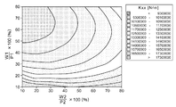
本発明者は本実施の形態に係る回転機器1の動圧増大作用を確かめるため、以下の条件でシミュレーションを行った。
・第1溝角度θ1:10度〜30度
・第1ラジアル動圧溝形成領域54の直径D1:1.5mm〜4.5mm
・第1ラジアル動圧溝形成領域54のラジアル動圧溝の数:8本〜12本
このような条件の下、シミュレーションでは、回転機器1を5000rpmで回転させ、溝比や溝の深さを種々変えながらラジアル剛性を計算した。
In order to confirm the dynamic pressure increasing action of the
First groove angle θ1: 10 degrees to 30 degrees Diameter D1 of first radial dynamic pressure groove forming region 54: 1.5 mm to 4.5 mm
-Number of radial dynamic pressure grooves in the first radial dynamic pressure groove forming region 54: 8 to 12 Under such conditions, in the simulation, the
図6は、代表的なシミュレーション結果を示す等高線図である。ここでは、直径D1=4.0mm、第1溝角度θ1=15度、ラジアル動圧溝の数=12本、に設定され、溝比は一定の0.3(すなわち、W1/P1=W2/P2=0.3)に設定された。Kxx(N/m)は、ラジアル剛性の大きさを表す。図6を参照すると、DE1が4μmから8μmの範囲内となるよう、且つ、DE2が2μmから3.5μmの範囲内となるようラジアル動圧溝を形成する場合、より大きなラジアル剛性を得ることができることが分かる。 FIG. 6 is a contour map showing typical simulation results. Here, the diameter D1 = 4.0 mm, the first groove angle θ1 = 15 degrees, the number of radial dynamic pressure grooves = 12, and the groove ratio is constant 0.3 (that is, W1 / P1 = W2 / P2 = 0.3). Kxx (N / m) represents the magnitude of radial rigidity. Referring to FIG. 6, when the radial dynamic pressure groove is formed so that DE1 is in the range of 4 μm to 8 μm and DE2 is in the range of 2 μm to 3.5 μm, greater radial rigidity can be obtained. I understand that I can do it.
図7は、代表的なシミュレーション結果を示す等高線図である。ここでは、直径D1=4.0mm、第1溝角度θ1=15度、ラジアル動圧溝の数=12本、に設定され、DE1は6.0μm、DE2は2.5μmに設定された。図7を参照すると、W1/P1が0.50(50%)から0.80(80%)の範囲内となるよう、且つ、W2/P2が0.10(10%)から0.30(30%)の範囲内となるようラジアル動圧溝を形成する場合、より大きなラジアル剛性を得ることができることが分かる。 FIG. 7 is a contour map showing typical simulation results. Here, the diameter D1 = 4.0 mm, the first groove angle θ1 = 15 degrees, the number of radial dynamic pressure grooves = 12, DE1 was set to 6.0 μm, and DE2 was set to 2.5 μm. Referring to FIG. 7, W1 / P1 is in the range of 0.50 (50%) to 0.80 (80%), and W2 / P2 is 0.10 (10%) to 0.30 ( It can be seen that when the radial dynamic pressure groove is formed so as to be within the range of 30%), a larger radial rigidity can be obtained.
以上、実施の形態に係る回転機器の構成と動作ついて説明した。この実施の形態は例示であり、それらの各構成要素の組み合わせにいろいろな変形例が可能なこと、またそうした変形例も本発明の範囲にあることは当業者に理解されるところである。 The configuration and operation of the rotating device according to the embodiment have been described above. This embodiment is an exemplification, and it is understood by those skilled in the art that various modifications can be made to combinations of the respective constituent elements, and such modifications are also within the scope of the present invention.
実施の形態では、円筒状マグネット32が積層コア40の外側に位置する、いわゆるアウターロータ型の回転機器について説明したが、これに限られない。たとえば円筒状マグネットが積層コアの内側に位置する、いわゆるインナーロータ型の回転機器に本実施の形態の技術的思想を適用してもよい。
In the embodiment, a so-called outer rotor type rotating device in which the
実施の形態では、軸受ユニット12がベース4に固定され、シャフト26が軸受ユニット12に対して回転する場合について説明したが、たとえばシャフトがベースに固定され、軸受ユニットがハブと共にシャフトに対して回転するようなシャフト固定型の回転機器に本実施の形態の技術的思想を適用してもよい。
In the embodiment, the case where the bearing
実施の形態では、ベース4に直接軸受ユニット12が取り付けられる場合について説明したが、これに限られない。例えば、回転体、軸受ユニット、積層コア、コイルおよびベースからなるブラシレスモータを別途形成した上で、そのブラシレスモータをシャーシに取り付ける構成としてもよい。
In the embodiment, the case where the bearing
第1および第2の実施の形態では積層コアを用いる場合について説明したが、コアは積層コアでなくてもよい。 In the first and second embodiments, the case where a laminated core is used has been described, but the core may not be a laminated core.
実施の形態では、溝比や溝の深さを線形的に変化させる場合について説明したが、これに限られず、溝比や溝の深さを段階的に変化させてもよく、あるいはまた、曲線的に変化させてもよい。 In the embodiment, the case where the groove ratio and the groove depth are linearly changed has been described. However, the present invention is not limited to this, and the groove ratio and the groove depth may be changed stepwise, or may be curved. May be changed.
実施の形態では、第1ラジアル動圧溝形成領域54のラジアル動圧溝は中央線68に対して略対称となるよう形成される場合について説明したが、これに限られない。例えば、上側形成領域の幅L1と下側形成領域の幅L2とは異なっていてもよい。各形成領域に形成されるラジアル動圧溝は、それらの形成領域の境界線に近いほど浅く且つ狭くなっていてもよい。
In the embodiment, the case where the radial dynamic pressure grooves of the first radial dynamic pressure
実施の形態では、各上側ラジアル動圧溝64の下側の縁66側の端部と対応する下側ラジアル動圧溝74の上側の縁62側の端部とは中央線68において連結されている場合について説明したが、これに限られない。図8は、変形例に係る第1ラジアル動圧溝形成領域154の展開図である。第1ラジアル動圧溝形成領域154は、上側形成領域70と同様の構成を有する第1領域170と、下側形成領域72と同様の構成を有する第2領域172と、軸方向で第1領域170と第2領域172とに挟まれている第3領域171と、を有する。第3領域171にはラジアル動圧溝は形成されない。すなわち、各上側ラジアル動圧溝164の下側の縁166側の端部164aと、その上側ラジアル動圧溝164に対応する下側ラジアル動圧溝174の上側の縁162側の端部174aとは軸方向に離間している。本変形例によると、実施の形態に係る回転機器1によって奏される作用効果と同様の作用効果が奏される。
In the embodiment, the end portion on the
1 回転機器、 2 トップカバー、 4 ベース、 6 回転体、 8 磁気記録ディスク、 10 データリード/ライト部、 12 軸受ユニット、 48 潤滑剤。 1 rotating device, 2 top cover, 4 base, 6 rotating body, 8 magnetic recording disk, 10 data read / write section, 12 bearing unit, 48 lubricant.
Claims (8)
前記潤滑剤が充填される隙間を形成する前記回転体の面および前記固定体の面のうちのいずれか一方には、前記回転体の回転軸を環囲すると共に前記回転体が回転するとき前記潤滑剤に動圧を生成する帯状の領域が形成され、
前記帯状の領域には、前記帯状の領域を横切る方向に沿って前記帯状の領域の両側から複数の溝が形成され、
前記帯状の領域の一方の側から形成される溝は前記帯状の領域の他方の側に近いほど浅く且つ狭くなるよう形成され、
前記帯状の領域の他方の側から形成される溝は前記帯状の領域の一方の側に近いほど浅く且つ狭くなるよう形成されることを特徴とする回転機器。 A rotating device including a fixed body that rotatably supports a rotating body via a lubricant,
When one of the surface of the rotating body and the surface of the fixed body forming a gap filled with the lubricant surrounds the rotation axis of the rotating body and the rotating body rotates, the rotating body rotates. A belt-like region that generates dynamic pressure in the lubricant is formed,
In the band-shaped region, a plurality of grooves are formed from both sides of the band-shaped region along a direction crossing the band-shaped region,
The groove formed from one side of the band-shaped region is formed so as to be shallower and narrower as it is closer to the other side of the band-shaped region,
The groove formed from the other side of the band-shaped region is formed to be shallower and narrower as it is closer to one side of the band-shaped region.
前記複数の溝は周方向に規則的に配列されることを特徴とする請求項1または2に記載の回転機器。 The band-shaped region is formed to be substantially parallel to the rotation axis,
The rotating device according to claim 1, wherein the plurality of grooves are regularly arranged in a circumferential direction.
前記帯状の領域は回転軸を中心とした円筒状の領域であってその直径は1.5mmから4.5mmの範囲内にあり、
前記複数の溝は前記帯状の領域の中央を通る線に対して対称となるよう形成され、
前記帯状の領域の一方の側から形成される溝の数は8本から12本の範囲内にあり、
前記帯状の領域の一方の側から形成される溝は、当該一方の側の端部における溝の深さが4μmから8μmの範囲内となるよう、且つ、前記帯状の領域の他方の側の端部における溝の深さが2μmから3.5μmの範囲内となるよう形成されることを特徴とする請求項1から3のいずれかに記載の回転機器。 An angle formed by a direction in which the band-shaped region extends and a direction crossing the band-shaped region is in a range of 10 degrees to 30 degrees;
The band-shaped region is a cylindrical region centered on the rotation axis, and the diameter thereof is in the range of 1.5 mm to 4.5 mm,
The plurality of grooves are formed so as to be symmetric with respect to a line passing through the center of the band-shaped region,
The number of grooves formed from one side of the band-shaped region is in the range of 8 to 12,
The groove formed from one side of the band-like region has an end on the other side of the band-like region so that the groove depth at the end of the one side is within a range of 4 μm to 8 μm. 4. The rotating device according to claim 1, wherein a depth of the groove in the portion is formed in a range of 2 μm to 3.5 μm.
前記帯状の領域の一方の側から形成される溝は、当該一方の側の端部における溝のピッチに対する溝の幅の比が0.50から0.80の範囲内となるよう、且つ、前記帯状の領域の他方の側の端部における溝のピッチに対する溝の幅の比が0.10から0.30の範囲内となるよう形成されることを特徴とする請求項4に記載の回転機器。 The plurality of grooves are regularly arranged in the circumferential direction,
The groove formed from one side of the band-shaped region has a ratio of the groove width to the groove pitch at the end of the one side in the range of 0.50 to 0.80, and 5. The rotating device according to claim 4, wherein the ratio of the groove width to the groove pitch at the end on the other side of the band-shaped region is in the range of 0.10 to 0.30. .
前記帯状の領域の他方の側の端部における溝の深さが、一方の側の端部における溝の深さの2/3未満となり、かつ、
前記帯状の領域の他方の側の端部における溝の深さに対する幅の比率が、一方の側の端部における溝の深さに対する幅の比率の0.67倍から1.50倍となるよう形成されることを特徴とする請求項1から6のいずれかに記載の回転機器。 The groove formed from one side of the band-shaped region is
The depth of the groove at the other end of the band-like region is less than 2/3 of the depth of the groove at the one end; and
The ratio of the width to the groove depth at the end on the other side of the band-shaped region is 0.67 to 1.50 times the ratio of the width to the groove depth at the end on the one side. The rotating device according to claim 1, wherein the rotating device is formed.
前記潤滑剤が充填される隙間を形成する前記回転体の面および前記固定体の面のうちのいずれか一方には、前記回転体の回転軸を環囲すると共に前記回転体が回転するとき前記潤滑剤に動圧を生成する帯状の領域が形成され、
前記帯状の領域には、前記帯状の領域を横切る方向に沿って前記帯状の領域の一方の側から他方の側に向かって複数の溝が形成され、
前記帯状の領域の一方の側から形成される溝は前記帯状の領域の他方の側に近いほど浅く且つ狭くなるよう形成されることを特徴とする回転機器。 A rotating device including a fixed body that rotatably supports a rotating body via a lubricant,
When one of the surface of the rotating body and the surface of the fixed body forming a gap filled with the lubricant surrounds the rotation axis of the rotating body and the rotating body rotates, the rotating body rotates. A belt-like region that generates dynamic pressure in the lubricant is formed,
In the band-shaped region, a plurality of grooves are formed from one side of the band-shaped region to the other side along a direction crossing the band-shaped region,
A groove formed from one side of the band-shaped region is formed so as to be shallower and narrower as it is closer to the other side of the band-shaped region.
Priority Applications (2)
| Application Number | Priority Date | Filing Date | Title |
|---|---|---|---|
| JP2012006024A JP2013145021A (en) | 2012-01-16 | 2012-01-16 | Rotating device |
| US13/736,717 US20130181558A1 (en) | 2012-01-16 | 2013-01-08 | Rotating device |
Applications Claiming Priority (1)
| Application Number | Priority Date | Filing Date | Title |
|---|---|---|---|
| JP2012006024A JP2013145021A (en) | 2012-01-16 | 2012-01-16 | Rotating device |
Publications (2)
| Publication Number | Publication Date |
|---|---|
| JP2013145021A true JP2013145021A (en) | 2013-07-25 |
| JP2013145021A5 JP2013145021A5 (en) | 2015-01-22 |
Family
ID=48779489
Family Applications (1)
| Application Number | Title | Priority Date | Filing Date |
|---|---|---|---|
| JP2012006024A Pending JP2013145021A (en) | 2012-01-16 | 2012-01-16 | Rotating device |
Country Status (2)
| Country | Link |
|---|---|
| US (1) | US20130181558A1 (en) |
| JP (1) | JP2013145021A (en) |
Cited By (2)
| Publication number | Priority date | Publication date | Assignee | Title |
|---|---|---|---|---|
| JP2015120122A (en) * | 2013-12-24 | 2015-07-02 | 三菱日立パワーシステムズ株式会社 | Roller bearing device and vertical mill |
| JP2016105005A (en) * | 2014-12-01 | 2016-06-09 | 日本電産株式会社 | Fluid bearing device, spindle motor, and disc drive unit |
Families Citing this family (5)
| Publication number | Priority date | Publication date | Assignee | Title |
|---|---|---|---|---|
| US9790990B2 (en) * | 2013-06-17 | 2017-10-17 | Seagate Technology Llc | Bearing gap determined depth and width |
| JP6466105B2 (en) * | 2014-09-01 | 2019-02-06 | Ntn株式会社 | Fluid dynamic bearing device and bearing member and shaft member used therefor |
| JP6577404B2 (en) * | 2016-04-05 | 2019-09-18 | ファナック株式会社 | Throttle unit, hydrostatic bearing device including the same, and method for manufacturing grooved block |
| CN110821950B (en) * | 2019-09-23 | 2021-08-13 | 西安交通大学 | Liquid dynamic pressure lubrication herringbone groove bearing with variable groove depth structure |
| US20230060983A1 (en) * | 2021-08-25 | 2023-03-02 | Wei-yung Lin | Hydrodynamic bearing |
Citations (4)
| Publication number | Priority date | Publication date | Assignee | Title |
|---|---|---|---|---|
| JP2002310145A (en) * | 2001-04-11 | 2002-10-23 | Daido Steel Co Ltd | Bearing mechanism, hard disk drive mechanism and polygon mirror drive mechanism using the same |
| JP2007333004A (en) * | 2006-06-12 | 2007-12-27 | Nippon Densan Corp | Hydrodynamic fluid bearing apparatus, spindle motor, and recording disk driving device equipped with this spindle motor |
| JP2010144778A (en) * | 2008-12-17 | 2010-07-01 | Nippon Densan Corp | Bearing device, spindle motor, and disk drive device |
| JP2011058595A (en) * | 2009-09-14 | 2011-03-24 | Alphana Technology Co Ltd | Disk drive device |
Family Cites Families (8)
| Publication number | Priority date | Publication date | Assignee | Title |
|---|---|---|---|---|
| WO2005078295A1 (en) * | 2004-02-18 | 2005-08-25 | Seiko Instruments Inc. | Fluid dynamic pressure bearing, motor, and recording medium drive device |
| JP4418531B2 (en) * | 2004-09-09 | 2010-02-17 | 日本電産株式会社 | Fluid dynamic bearing device and spindle motor |
| DE102004045629B4 (en) * | 2004-09-21 | 2008-07-03 | Minebea Co., Ltd. | Fluid dynamic storage system |
| JP2006283773A (en) * | 2005-03-31 | 2006-10-19 | Matsushita Electric Ind Co Ltd | Dynamic pressure fluid bearing device and small-sized motor having the same |
| JP5563775B2 (en) * | 2009-03-17 | 2014-07-30 | サムスン電機ジャパンアドバンスドテクノロジー株式会社 | Disk drive |
| JP2011002024A (en) * | 2009-06-18 | 2011-01-06 | Nippon Densan Corp | Bearing apparatus, spindle motor, and disk drive apparatus |
| KR101179323B1 (en) * | 2011-02-24 | 2012-09-03 | 삼성전기주식회사 | Hydrodynamic bearing assembly and motor including the same |
| JP2013007469A (en) * | 2011-06-27 | 2013-01-10 | Nippon Densan Corp | Method of manufacturing fluid dynamic pressure bearing mechanism, motor, and disk drive device |
-
2012
- 2012-01-16 JP JP2012006024A patent/JP2013145021A/en active Pending
-
2013
- 2013-01-08 US US13/736,717 patent/US20130181558A1/en not_active Abandoned
Patent Citations (4)
| Publication number | Priority date | Publication date | Assignee | Title |
|---|---|---|---|---|
| JP2002310145A (en) * | 2001-04-11 | 2002-10-23 | Daido Steel Co Ltd | Bearing mechanism, hard disk drive mechanism and polygon mirror drive mechanism using the same |
| JP2007333004A (en) * | 2006-06-12 | 2007-12-27 | Nippon Densan Corp | Hydrodynamic fluid bearing apparatus, spindle motor, and recording disk driving device equipped with this spindle motor |
| JP2010144778A (en) * | 2008-12-17 | 2010-07-01 | Nippon Densan Corp | Bearing device, spindle motor, and disk drive device |
| JP2011058595A (en) * | 2009-09-14 | 2011-03-24 | Alphana Technology Co Ltd | Disk drive device |
Cited By (2)
| Publication number | Priority date | Publication date | Assignee | Title |
|---|---|---|---|---|
| JP2015120122A (en) * | 2013-12-24 | 2015-07-02 | 三菱日立パワーシステムズ株式会社 | Roller bearing device and vertical mill |
| JP2016105005A (en) * | 2014-12-01 | 2016-06-09 | 日本電産株式会社 | Fluid bearing device, spindle motor, and disc drive unit |
Also Published As
| Publication number | Publication date |
|---|---|
| US20130181558A1 (en) | 2013-07-18 |
Similar Documents
| Publication | Publication Date | Title |
|---|---|---|
| JP2013145021A (en) | Rotating device | |
| JP5166323B2 (en) | Disk drive device and production method thereof | |
| JP5519314B2 (en) | Rotating equipment | |
| JP2011090739A (en) | Disk drive device | |
| JP3727253B2 (en) | Hydrodynamic bearing device | |
| JP2012145157A (en) | Rotating device and method for manufacturing the rotating device | |
| US8213113B2 (en) | Disk drive device with vibration reduction of second order rocking-mode resonance | |
| US20120049680A1 (en) | Rotating device having rotor, stator, and driving mechanism | |
| US8757883B2 (en) | Disk drive device | |
| JP5717953B2 (en) | Disk drive | |
| US8913343B2 (en) | Rotating device using a fluid dynamic bearing with magnet and suction plate | |
| JP2014060909A (en) | Spindle motor and hard disk drive including the same | |
| JP5553641B2 (en) | Magnetizing apparatus and method for manufacturing rotating device | |
| JP2006170431A (en) | Fluid dynamic pressure bearing device and spindle motor mounted therewith as well as recording disc drive mechanism | |
| US8922944B2 (en) | Rotating device | |
| JP5210054B2 (en) | Motor and disk drive using the same | |
| JP2014082349A (en) | Magnetization device, method of manufacturing rotary apparatus and rotary apparatus | |
| JP2012165627A (en) | Rotary apparatus | |
| US8368282B2 (en) | Disk drive device rotationally driving recording disk | |
| JP2009024771A (en) | Bearing unit, motor fitted with this bearing unit and disk driving device | |
| JP2014032713A (en) | Rotary equipment | |
| JP5519173B2 (en) | Disk drive | |
| US20150340057A1 (en) | Disk drive unit and method of manufacturing the same | |
| JP2009177923A (en) | Motor and recording medium drive device | |
| US20150152916A1 (en) | Rotating device |
Legal Events
| Date | Code | Title | Description |
|---|---|---|---|
| RD02 | Notification of acceptance of power of attorney |
Free format text: JAPANESE INTERMEDIATE CODE: A7422 Effective date: 20141010 |
|
| A521 | Request for written amendment filed |
Free format text: JAPANESE INTERMEDIATE CODE: A523 Effective date: 20141203 |
|
| A621 | Written request for application examination |
Free format text: JAPANESE INTERMEDIATE CODE: A621 Effective date: 20141210 |
|
| A977 | Report on retrieval |
Free format text: JAPANESE INTERMEDIATE CODE: A971007 Effective date: 20150910 |
|
| A131 | Notification of reasons for refusal |
Free format text: JAPANESE INTERMEDIATE CODE: A131 Effective date: 20151013 |
|
| A02 | Decision of refusal |
Free format text: JAPANESE INTERMEDIATE CODE: A02 Effective date: 20160308 |