JP2013137358A - Terminal processing method for optical fiber cable - Google Patents
Terminal processing method for optical fiber cable Download PDFInfo
- Publication number
- JP2013137358A JP2013137358A JP2011287224A JP2011287224A JP2013137358A JP 2013137358 A JP2013137358 A JP 2013137358A JP 2011287224 A JP2011287224 A JP 2011287224A JP 2011287224 A JP2011287224 A JP 2011287224A JP 2013137358 A JP2013137358 A JP 2013137358A
- Authority
- JP
- Japan
- Prior art keywords
- optical fiber
- metal tape
- processing method
- fiber cable
- optical cable
- Prior art date
- Legal status (The legal status is an assumption and is not a legal conclusion. Google has not performed a legal analysis and makes no representation as to the accuracy of the status listed.)
- Pending
Links
Images


Abstract
Description
本発明は、光ファイバケーブルの端末処理方法に関する。 The present invention relates to an optical fiber cable terminal processing method.
従来の光モジュールは、光ファイバケーブル(以下、単に光ケーブルと云う。)の光ファイバと接続される光電変換部が搭載された回路基板と、回路基板を収容する金属製の筐体を備えている。この光モジュールは、入出力される電気信号を光電変換部により光信号に変換し、光信号による信号伝送を行っている。 A conventional optical module includes a circuit board on which a photoelectric conversion unit connected to an optical fiber of an optical fiber cable (hereinafter simply referred to as an optical cable) is mounted, and a metal housing that houses the circuit board. . In this optical module, an input / output electric signal is converted into an optical signal by a photoelectric conversion unit, and signal transmission using the optical signal is performed.
この光モジュールに使用される光ケーブルは、単心又は多心の光ファイバ心線の外周を金属管で覆われ、その外周に光ケーブルの引っ張り強度を高める抗張力繊維が縦添えされ、さらにその外周に外被で覆われた金属管型光ケーブルが知られている(例えば、特許文献1参照)。 In the optical cable used in this optical module, the outer periphery of a single-core or multi-core optical fiber is covered with a metal tube, and the outer periphery is provided with tensile strength fibers that increase the tensile strength of the optical cable. A metal tube type optical cable covered with a cover is known (for example, see Patent Document 1).
ところで、パソコンなどの電子機器の接続に使用される光ケーブルは、光ファイバの外周に絶縁樹脂製のインナーチューブを有しており、その外周に抗張力繊維を有し、その抗張力繊維の外周に伝熱部材として金属編組を有し、その外周に外被を有している。金属編組の場合、錫めっき導線を編み込む工程が必要であり、生産性(製造線速)の向上を図る上で銅製の金属テープが使用されている。この金属テープの巻き方は、光ファイバの軸線に沿って縦添えされるタイプと、光ファイバの外周に螺旋巻きされるタイプがある。 By the way, an optical cable used for connecting an electronic device such as a personal computer has an inner tube made of an insulating resin on the outer periphery of the optical fiber, has a tensile fiber on the outer periphery, and heat transfer on the outer periphery of the tensile fiber. It has a metal braid as a member and has a jacket on its outer periphery. In the case of a metal braid, a step of braiding a tin-plated conductive wire is required, and a copper metal tape is used to improve productivity (production line speed). There are two types of winding of the metal tape: a type that is vertically attached along the axis of the optical fiber, and a type that is spirally wound around the outer periphery of the optical fiber.
しかしながら、光モジュールとの接続作業において、巻かれている金属テープを解くか除去して光ファイバを露出させる外被除去工程、および金属テープの除去端部を折り返す折り返し工程が煩雑となり、作業効率の低下を招いている。 However, in the connection work with the optical module, the outer cover removing process of unwrapping or removing the wound metal tape to expose the optical fiber and the folding process of turning back the removed end of the metal tape become complicated, and work efficiency is improved. It is causing a decline.
本発明の目的は、光モジュールとの接続作業における作業性の向上を図ることができる光ケーブルの端末処理方法を提供することにある。 The objective of this invention is providing the terminal processing method of the optical cable which can aim at the improvement of workability | operativity in the connection operation | work with an optical module.
上記課題を解決することができる本発明に係る光ケーブルの端末処理方法は、光ファイバの外側にテープ状の金属層を有し、前記金属層の外側に外被を有する光ケーブルの前記外被を端部から所定の長さ除去する外被除去工程と、前記金属層を所定長さ折り返して、前記外被の端部の周囲に被せる折り返し工程と、を有する光ケーブルの端末処理方法であって、
前記折り返し工程は、前記外被除去工程後、露出した前記金属層の端部から所定長さの切り込み部が折り返し方向に沿って形成され、前記金属層が前記切り込み部から剥離されて前記外被端部の周囲に折り返されることを特徴としている。
An optical cable terminal processing method according to the present invention capable of solving the above-described problems is provided with an end of the outer sheath of an optical cable having a tape-shaped metal layer on the outer side of an optical fiber, and an outer sheath on the outer side of the metal layer An optical cable terminal processing method comprising: a jacket removing step of removing a predetermined length from a portion; and a folding step of folding the metal layer by a predetermined length and covering the periphery of an end of the jacket;
In the folding step, a cut portion having a predetermined length is formed along the folding direction from the exposed end portion of the metal layer after the outer cover removing step, and the metal layer is peeled off from the cut portion to form the outer cover. It is characterized by being folded around the edge.
また、本発明に係る光ケーブルの端末処理方法は、前記金属層が前記光ファイバの外側に螺旋状に巻き付けられていることが好ましい。 In the optical cable terminal processing method according to the present invention, it is preferable that the metal layer is spirally wound around the outside of the optical fiber.
また、本発明に係る光ケーブルの端末処理方法は、前記切り込み部が巻き付け方向に沿って螺旋状に形成されることが好ましい。 In the optical cable terminal processing method according to the present invention, it is preferable that the cut portion is formed in a spiral shape along the winding direction.
また、本発明に係る光ケーブルの端末処理方法は、前記切り込み部が前記金属層の巻きはじめの端部に形成されることが好ましい。 In the optical cable terminal processing method according to the present invention, it is preferable that the cut portion is formed at an end portion of the metal layer at the beginning of winding.
また、本発明に係る光ケーブルの端末処理方法は、前記折り返し工程の後、前記外被と前記外被の内側に介在する前記金属層および折り返された前記金属層を端末固定具に圧着する圧着工程を有することが好ましい。 Further, in the optical cable terminal processing method according to the present invention, after the folding step, the outer cover and the metal layer interposed inside the outer cover and the crimped metal layer are crimped to the terminal fixture. It is preferable to have.
本発明に係る光ケーブルの端末処理方法によれば、折り返し工程は、外被除去工程後、露出した金属層の端部から所定長さの切り込み部が折り返し方向に沿って形成され、金属層が切り込み部から剥離されて折り返される。これにより、光モジュールとの接続作業における作業性の向上を図ることができる。 According to the optical fiber terminal processing method according to the present invention, the folding process includes forming a cut portion having a predetermined length from the end of the exposed metal layer along the folding direction after the outer cover removing process, and cutting the metal layer. It peels from the part and is folded back. Thereby, the workability | operativity in the connection operation | work with an optical module can be aimed at.
以下、本発明に係る光ケーブルの端末処理方法の好適な実施形態を図面に基づいて説明する。 DESCRIPTION OF EXEMPLARY EMBODIMENTS Hereinafter, preferred embodiments of an optical cable terminal processing method according to the invention will be described with reference to the drawings.
(実施形態1)
光モジュールは、光通信技術などにおいて信号(データ)の伝送に用いられるものであり、接続先のパソコンなどといった電子機器に電気的に接続され、入出力される電気信号を光信号に変換して光信号を伝送するものである。
(Embodiment 1)
An optical module is used for transmission of signals (data) in optical communication technology, etc., and is electrically connected to an electronic device such as a connected personal computer, and converts an input / output electric signal into an optical signal. An optical signal is transmitted.
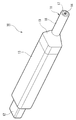
図1に示すように、本実施形態の光モジュール10は、光ケーブル11の端部にコネクタモジュールが接続されている。このコネクタモジュールは、先端側に設けられる電気コネクタ12と、回路基板24を収容した金属製の筐体20(図3参照)を被う外装ハウジング13と、を備えている。光ケーブル11と筐体20との接続部分はブーツ19によって被われている。
As shown in FIG. 1, in the
図2に示すように、光ケーブル11は、その横断面で見た中央に、光ファイバテープ心線14aを有する。光ファイバテープ心線14aは、複数(本例では4本)の光ファイバ心線14を平面上に並列させて被覆樹脂でテープ状に一体化されたものである。光ファイバテープ心線14aは、インナーチューブ15の内側に収容されている。インナーチューブ15の周囲には抗張力繊維の束を沿わせてなる介在層16が設けられている。介在層16の外周には金属層である金属テープ17が設けられている。金属テープ17の外周には絶縁樹脂からなる外被18が設けられている。
As shown in FIG. 2, the
光ファイバ心線14は、コアとクラッドが石英ガラスである光ファイバ(AGF:All Glass Fiber)、クラッドが硬質プラスチックからなる光ファイバ(HPCF:Hard Plastic Clad Fiber)、等を用いることができる。ガラスのコア径が80μmの細径HPCFを用いると、光ファイバ心線14が小径に曲げられても破断しにくい。複数の光ファイバ心線14をテープ化せず単心のままインナーチューブ15内に収容することもできるが、テープ化されていると、単心の光ファイバ心線14同士が交差して側圧がかかることによるマイクロベンドロスの発生を防ぐことができる。なお、光ファイバテープ心線14aは複数本設けられていても良い。
As the
インナーチューブ15は、ノンハロゲン難燃性樹脂である例えばPVC(Polyvinylchloride)などの絶縁樹脂からなる。インナーチューブ15は、例えば、外径が2.0mm、厚さが0.55mmである。介在層16は、例えば極細径のアラミド繊維であり、束状に集合された状態で光ケーブル11に内蔵されている。介在層16は光ケーブル11における抗張力機能を有する。以下、介在層16を、抗張力繊維と云う。
The
本実施形態に係る金属テープ17は、例えば、錫めっきした銅テープ2本を介在層16の外周に縦添えしたものであり、放熱層としての機能を有する。金属テープ17の熱伝導率は、例えば400W/m・Kである。外被18は、例えばポリオレフィンなどの絶縁樹脂から形成されている。外被18は、例えば、外径が4.2mm、厚さが0.5mmである。このような構成の光ケーブル11は、光ファイバ心線14の側圧特性と、ケーブルとしての柔軟性に優れ、さらに放熱性にも優れている。
The
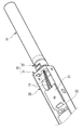
図3に示すように、筐体20は、断面が略矩形形状を呈する筒状の収容部材であり、光ファイバ心線14が接続される光電変換部21が搭載された回路基板22などを収容する収容空間を画成している。また、筐体20は、前端部に電気コネクタ12が設けられ、後端部に光ケーブル11を固定する光ケーブル端末固定具30が連結されている。筐体20の材質は、鋼(Fe系)、ブリキ(錫めっき銅)、ステンレス、銅、真鍮、アルミなどの熱伝導率の高い(好ましくは100W/m・K以上)金属材料により形成されている。
As shown in FIG. 3, the
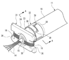
本発明に係る光ケーブルの端末処理方法の一実施形態を図4に基づいて説明する。本実施形態の光ケーブル11は、光ファイバ心線14の外側にインナーチューブ15を有し、その外側に抗張力繊維16を有し、その外側に金属テープ17を有し、金属テープ17の外側に外被18を有している。
An embodiment of an optical cable terminal processing method according to the present invention will be described with reference to FIG. The
(外被除去工程)
図4(a)に示すように、光ケーブル11の外被除去工程は、光ケーブル11の外被18を端部から所定の長さ除去することで、金属テープ17が露出される。この金属テープ17は、光ファイバ心線14の軸線に沿って重ね部25を形成するように縦添えされている。なお、重ね部25では、金属テープ17同士が接着されている場合もある。
(Coating removal process)
As shown in FIG. 4A, in the jacket removal process of the
(折り返し工程)
折り返し工程は、金属テープ17を所定長さ折り返して、外被18の端部の周囲に被せる工程である。先ず、図4(b)に示すように、金属テープ17の除去部17aに、光ファイバ心線14の軸線に沿い且つ金属テープ17の外周上の対向位置(本実施形態では重ね部25の近傍)に2本の切り込み部26a,26bが専用治具によって形成される。
(Wrapping process)
The folding process is a process in which the
これにより、金属テープ17の除去部17aは、仮に重ね部25が接着されていても、インナーチューブ15上から上下方向に容易に剥すことができる。なお、図中、太い実線が紙面表側の切り込み部26aであり、太い破線が紙面裏側の切り込み部26bである。また、切り込み部26a,26bは、2本に限らず3本以上形成しても良い。また、切り込み部26a,26bの形成位置も任意に選択することができる。
Thereby, the
図4(c)に示すように、金属テープ17の除去部17aが外被18の端部の外側に折り返される。これにより、金属テープ17の折り返し部17bが外被18の端部の外側に形成される。そして、金属テープ17の除去部17aが折り返されることで金属テープ17が除去された部分では、インナーチューブ15が切断されて除去される。したがって、光モジュール10との接続作業における作業性の向上を図ることができる。なお、折り返された金属テープ17の不要な部分は、切断して除去しても良い。
As shown in FIG. 4C, the
(圧着工程)
圧着工程は、折り返し工程の後、外被18および外被18の内側に介在する金属テープ17、そして、折り返された金属テープ17の折り返し部17bを端末固定具に圧着する工程である。
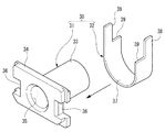
図5に示すように、光ケーブル端末固定具30は、本体部31と圧着部32の2部品構成である。本体部31は、外被18を固定する外被固定部33と、その内部に光ファイバ心線14を挿通するケーブル挿通路35と、本体部31の前端に配置された平板状の基部34と、から構成されている。外被固定部33の外周面は、表面加工されて滑らかになっているので、加締めにより金属テープ17や外被18を傷付けることなくスムースに行うことができる。基部34のケーブル挿通路35の両側には、光ケーブル11の抗張力繊維16を複数本に束ねた抗張力線を外被固定部33側の後方へ引き回す凹部36を有している。
(Crimping process)
The crimping step is a step of crimping the
As shown in FIG. 5, the optical
圧着部32は、外被固定部33の外周面に加締められるU字形状の圧着具であり、両端に圧着片38と、この圧着片38に隣接して切り欠き部39を有している。圧着部32は、外被固定部33への加締め時に一端側の切り欠き部39に他端側の圧着片38が加締められる。圧着部32の内周面37は、表面加工されて滑らかになっていることで、加締め作業を外被18を傷付けることなくスムースに行うことができる。
The crimping
先ず、光ケーブル11の光ケーブル端末固定具30への取り付け手順の一例を説明する。
図6に示すように、光ケーブル11の光ファイバ心線14、インナーチューブ15および抗張力繊維16が本体部31のケーブル挿通路35に挿通されると共に、金属テープ17の折り返し部17bと外被18が外被固定部33の外周に被せられる。
First, an example of a procedure for attaching the
As shown in FIG. 6, the optical
次に、ケーブル挿通路35から挿通された抗張力繊維16が、基部34の表面側から凹部36を通して外被固定部33側に引き出される。そして、圧着部32が外被18の外周側に折り返された金属テープ17の折り返し部17bのところに移動されるとともに、引き出されていた抗張力繊維16が圧着部32の内周面37側に押し込まれる。
Next, the
次に、図7に示すように、圧着部32が専用の加締治具によって金属テープ17の折り返し部17bの外周面の全周にわたって圧着される。このとき、一端側の切り欠き部39に他端側の圧着片38が加締められる。これにより、図8に示すように、光ケーブル11が光ケーブル端末固定具30に保持固定されると共に、外被18、金属テープ17および抗張力繊維16が外被固定部33と圧着部32との間に挟持される。
Next, as shown in FIG. 7, the crimping
最後に、光ケーブル端末固定具30が筐体20の後端部に結合されることにより、筐体20と光ケーブル端末固定具30とが物理的且つ熱的に接続される。即ち、筐体20と光ケーブル11の金属テープ17とが熱的に接続される。
Finally, the optical
上記のように光ケーブル11が抗張力繊維16と外被18の間に金属テープ17を有し、金属テープ17は外被固定部33と外被18の間に介在し、金属テープ17は外被固定部33の外周面に加締められる圧着部32によって外被18の外周から外被固定部33の外周面に圧着される。このようにすれば金属テープ17が外被固定部33と強固に熱的に接続され、外被固定部33と連結する筐体20から、熱を光ケーブル11側へ逃がすことができる。そして、金属テープ17から外被18を通して、熱を外部に効率良く放出できる。
As described above, the
さらに、金属テープ17を筐体20に半田付けすることによって熱的に接続された光ケーブル端末固定具30がより強固に筐体20に結合されることで、筐体20と光ケーブル端末固定具30が熱的に接続される。これにより、筐体20内で発生した熱を光ケーブル端末固定具30からより効率良く放熱させることができ、熱に強い光モジュール10を得ることができる。
Furthermore, the optical
(実施形態2)
次に、本発明に係る光ケーブルの端末処理方法の別の実施形態を図9に基づいて説明する。なお、上記実施形態と同一構成の説明は、同一符号を付すことで説明は省略する。また、圧着工程については、同一構成の光ケーブル端末固定具を使用することで、説明は省略する。
(Embodiment 2)
Next, another embodiment of the optical cable terminal processing method according to the present invention will be described with reference to FIG. In addition, description of the same structure as the said embodiment is abbreviate | omitted by attaching | subjecting the same code | symbol. Moreover, about a crimping | compression-bonding process, description is abbreviate | omitted by using the optical cable terminal fixture of the same structure.
(外被除去工程)
図9(a)に示すように、光ケーブル11の外被除去工程は、光ケーブル11の外被18を端部から所定の長さ除去することで、金属テープ17が露出される。この金属テープ17は、光ファイバ心線14の軸線に沿って螺旋状の重ね部25を形成するように、図中左側から右側方向へ螺旋巻きされている。それ故、金属テープ17は左端部から螺旋巻きを解くことはできない。なお、螺旋巻きの場合も重ね部25では、金属テープ17同士が接着されている場合もある。
(Coating removal process)
As shown in FIG. 9A, in the jacket removal process of the
(折り返し工程)
図9(b)に示すように、先ず、金属テープ17の除去部17aに、光ファイバ心線14の軸線に沿い且つ金属テープ17の外周上の対向位置に2本の切り込み部26a,26bが専用治具によって形成される。即ち、切り込み部26a,26bは金属テープ17の巻きはじめの端部に形成される。これにより、金属テープ17の除去部17aは、仮に重ね部25が接着された螺旋巻きであっても図中上下に分割され、インナーチューブ15上から容易に剥すことができる。
(Wrapping process)
As shown in FIG. 9B, first, two
図9(c)に示すように、金属テープ17の除去部17aが外被18の端部の外側に折り返される。これにより、金属テープ17の折り返し部17bが外被18の端部の外側に形成される。そして、金属テープ17の除去部17aが折り返されることで金属テープ17が除去された部分では、インナーチューブ15が切断されて除去される。したがって、螺旋巻きの金属テープ17であっても上記同様に光モジュール10との接続作業における作業性の向上を図ることができる。なお、折り返された金属テープ17の不要な部分は、切断して除去しても良い。
As shown in FIG. 9C, the
(実施形態3)
次に、本発明に係る光ケーブルの端末処理方法のさらに別の実施形態を図10に基づいて説明する。なお、上記実施形態と同一構成の説明は、同一符号を付すことで説明は省略する。また、圧着工程については、同一構成の光ケーブル端末固定具を使用することで、説明は省略する。
(Embodiment 3)
Next, still another embodiment of the optical cable terminal processing method according to the present invention will be described with reference to FIG. In addition, description of the same structure as the said embodiment is abbreviate | omitted by attaching | subjecting the same code | symbol. Moreover, about a crimping | compression-bonding process, description is abbreviate | omitted by using the optical cable terminal fixture of the same structure.
(外被除去工程)
図10(a)に示すように、光ケーブル11の外被除去工程は、光ケーブル11の外被18を端部から所定の長さ除去することで、金属テープ17が露出される。この金属テープ17は、上記同様に光ファイバ心線14の軸線に沿って螺旋状の重ね部25を形成するように、図中左側から右側方向へ螺旋巻きされている。
(Coating removal process)
As shown in FIG. 10A, in the jacket removal process of the
(折り返し工程)
図10(b)に示すように、先ず、金属テープ17の除去部17aに、巻き付け方向である螺旋状の重ね部25に沿い且つ金属テープ17の外周上の対向位置に2本の切り込み部26a,26bが専用治具によって螺旋状に形成される。即ち、切り込み部26a,26bは金属テープ17の巻きはじめの端部に形成される。なお、最初の切り込み部26a,26bは、光ファイバ心線14の軸線に沿って形成される。これにより、金属テープ17の除去部17aは、仮に重ね部25が接着された螺旋巻きであっても、図中上下に分割され、インナーチューブ15上から容易に剥すことができる。
(Wrapping process)
As shown in FIG. 10 (b), first, two
図10(c)に示すように、金属テープ17の接続部17cは除去されずに解かれる。そして、金属テープ17の接続部17cが筐体20に圧着又は半田付けされる。また、金属テープ17の折り返し部17bが外被18の端部の外側に折り返され、金属テープ17が除去された部分では、インナーチューブ15が切断されて除去される。したがって、螺旋巻きの金属テープ17であっても上記同様に光モジュール10との接続作業における作業性の向上を図ることができる。なお、折り返された金属テープ17の不要な部分は、切断して除去しても良い。
As shown in FIG. 10 (c), the connecting
上述したように上記各実施形態の光ケーブルの端末処理方法は、光ファイバ心線14の外側に金属テープ17を有し、金属テープ17の外側に外被18を有する光ケーブル11の外被18を端部から所定の長さ除去する外被除去工程と、金属テープ17を所定長さ折り返して、外被18の端部の周囲に被せる折り返し工程と、を有している。そして、折り返し工程は、外被除去工程後、露出した金属テープ17の端部から所定長さの切り込み部26a,26bが折り返し方向に沿って形成され、金属テープ17が切り込み部26a,26bから剥離されて外被18の端部の周囲に折り返される。
As described above, the end processing method of the optical cable according to each of the above-described embodiments has the
前記構成の光ケーブルの端末処理方法によれば、折り返し工程は、外被除去工程後、露出した金属テープ17の端部から所定長さの切り込み部26a,26bが折り返し方向に沿って形成され、金属テープ17の除去部17aが切り込み部26a,26bから剥離されて容易に除去されるので、光モジュール10との接続作業における作業性の向上を図ることができる。
According to the optical cable terminal processing method having the above-described configuration, in the folding step, the
また、金属テープ17が光ファイバ心線14の外側に螺旋状に巻き付けられていれば、金属テープ17の伝熱面積を増やすことができるので、放熱効率を向上させることができる。
Further, if the
また、切り込み部26a,26bが巻き付け方向に沿って螺旋状に形成されていれば、金属テープ17を解いてその端部を筐体20に圧着又は半田付けさせる場合に容易に金属テープ17を解くことができる。これにより、光モジュール10との接続作業における作業性の向上を一層図ることができる。
Further, if the
また、通常、重ね巻きによる螺旋巻きの場合は、巻きはじめの端部から解くことができないが、切り込み部26a,26bが金属テープ17の巻きはじめの端部に形成されていれば、切り込み部26a,26bに沿って容易に金属テープ17を解くことができる。
Usually, in the case of spiral winding by lap winding, it cannot be unwound from the end portion at the beginning of winding, but if the
また、折り返し工程の後、金属テープ17を光ケーブル端末固定具30に圧着する圧着工程を有していれば、光ケーブル11の外被18および金属テープ17と共に抗張力繊維16を光ケーブル端末固定具30で挟持させることができ、引っ張りに強い光ケーブルの端末構造を形成することができる。
In addition, if the
なお、本発明の光ケーブルの端末処理方法は、上述した実施形態に限定されるものではなく、適宜、変形、改良等が自在である。 In addition, the terminal processing method of the optical cable of this invention is not limited to embodiment mentioned above, A deformation | transformation, improvement, etc. are possible suitably.
10…光モジュール、11…光ケーブル、14…光ファイバ心線、15…インナーチューブ、16…介在層(抗張力繊維)、17…金属テープ(金属層)、17a…除去部、17b…折り返し部、17c…接続部、18…外被、20…筐体、21…光電変換部、22…回路基板、25…重ね部、26a,26b…切り込み部、30…光ケーブル端末固定具
DESCRIPTION OF
Claims (5)
前記折り返し工程は、前記外被除去工程後、露出した前記金属層の端部から所定長さの切り込み部が形成され、前記金属層が前記切り込み部から剥離されて前記外被端部の周囲に折り返されることを特徴とする光ファイバケーブルの端末処理方法。 A jacket removing step of removing a predetermined length of the jacket of the optical fiber cable having a tape-shaped metal layer outside the optical fiber and having a jacket outside the metal layer; and the metal layer A folding step of folding a predetermined length around the end portion of the jacket, and a terminal processing method for an optical fiber cable,
In the folding step, a cut portion having a predetermined length is formed from the exposed end portion of the metal layer after the outer cover removing step, and the metal layer is peeled off from the cut portion and is formed around the outer cover end portion. An end processing method for an optical fiber cable, wherein the end processing method is performed.
前記金属層が前記光ファイバの外側に螺旋状に巻き付けられていることを特徴とする光ファイバケーブルの端末処理方法。 In the terminal processing method of the optical fiber cable according to claim 1,
An end processing method for an optical fiber cable, wherein the metal layer is spirally wound around the outer side of the optical fiber.
前記切り込み部が巻き付け方向に沿って螺旋状に形成されることを特徴とする光ファイバケーブルの端末処理方法。 In the terminal processing method of the optical fiber cable according to claim 2,
The method of processing an end of an optical fiber cable, wherein the cut portion is formed in a spiral shape along a winding direction.
前記切り込み部が前記金属層の巻きはじめの端部に形成されることを特徴とする光ファイバケーブルの端末処理方法。 In the optical fiber cable terminal processing method according to any one of claims 1 to 3,
The method of processing an end of an optical fiber cable, wherein the cut portion is formed at an end portion of the metal layer at the beginning of winding.
前記折り返し工程の後、前記外被と前記外被の内側に介在する前記金属層および折り返された前記金属層を端末固定具に圧着する圧着工程を有することを特徴とする光ファイバケーブルの端末処理方法。
In the terminal processing method of the optical fiber cable according to claim 1,
After the folding step, there is a crimping step of crimping the outer layer, the metal layer interposed inside the outer jacket, and the folded metal layer to a terminal fixture, and terminating the optical fiber cable. Method.
Priority Applications (1)
| Application Number | Priority Date | Filing Date | Title |
|---|---|---|---|
| JP2011287224A JP2013137358A (en) | 2011-12-28 | 2011-12-28 | Terminal processing method for optical fiber cable |
Applications Claiming Priority (1)
| Application Number | Priority Date | Filing Date | Title |
|---|---|---|---|
| JP2011287224A JP2013137358A (en) | 2011-12-28 | 2011-12-28 | Terminal processing method for optical fiber cable |
Publications (1)
| Publication Number | Publication Date |
|---|---|
| JP2013137358A true JP2013137358A (en) | 2013-07-11 |
Family
ID=48913152
Family Applications (1)
| Application Number | Title | Priority Date | Filing Date |
|---|---|---|---|
| JP2011287224A Pending JP2013137358A (en) | 2011-12-28 | 2011-12-28 | Terminal processing method for optical fiber cable |
Country Status (1)
| Country | Link |
|---|---|
| JP (1) | JP2013137358A (en) |
-
2011
- 2011-12-28 JP JP2011287224A patent/JP2013137358A/en active Pending
Similar Documents
| Publication | Publication Date | Title |
|---|---|---|
| KR101795031B1 (en) | Composite optical fiber cable and composite optical fiber cable assembly | |
| JP5737245B2 (en) | Optical cable terminal fixture, optical cable terminal fixing structure, and optical module | |
| JP6212994B2 (en) | Optical module | |
| JP2008153030A (en) | Cable with identification function | |
| US20140060882A1 (en) | Communication cable having at least one insulated conductor | |
| JP5463849B2 (en) | Multi-core coaxial cable and manufacturing method thereof | |
| WO2013100051A1 (en) | Optical fiber and optical cable | |
| JP2008166251A (en) | Multicore cable harness and multicore cable harness with connector | |
| JP5581842B2 (en) | Photoelectric composite cable | |
| JP4523771B2 (en) | Twisted pair cable | |
| JP2009205982A (en) | Conductor and method of manufacturing the same | |
| JP5191822B2 (en) | Shield connector | |
| JP2013137358A (en) | Terminal processing method for optical fiber cable | |
| JP2016100200A (en) | Shield wire and method for producing the same | |
| US10983292B1 (en) | QSFP-DD backshell | |
| JP6344214B2 (en) | Photoelectric composite cable | |
| JP5494213B2 (en) | Photoelectric composite cable | |
| JP2013037840A (en) | Shield cable, multicore cable, method for forming terminal of shield cable, and method for forming terminal of multicore cable | |
| JP2005050622A (en) | Terminal processed cable and its manufacturing method | |
| JP2013137348A (en) | Terminal anchoring structure of optical cable and optical module | |
| JP2010244800A (en) | Composite harness and method for manufacturing the same | |
| JP5299311B2 (en) | Multi-core cable with connector and manufacturing method thereof | |
| EP4167007A1 (en) | Connector member, optical transmission system, and assembly method for same | |
| JP4922320B2 (en) | Connection structure and connection method of optoelectric composite cable and ferrule | |
| JP2016081568A (en) | Cable terminal structure |