JP2013132046A - Video decoder, video decoding method, video decoding program, receiver, receiving method, and receiving program - Google Patents
Video decoder, video decoding method, video decoding program, receiver, receiving method, and receiving program Download PDFInfo
- Publication number
- JP2013132046A JP2013132046A JP2012254949A JP2012254949A JP2013132046A JP 2013132046 A JP2013132046 A JP 2013132046A JP 2012254949 A JP2012254949 A JP 2012254949A JP 2012254949 A JP2012254949 A JP 2012254949A JP 2013132046 A JP2013132046 A JP 2013132046A
- Authority
- JP
- Japan
- Prior art keywords
- prediction
- motion vector
- decoded
- decoding
- inter
- Prior art date
- Legal status (The legal status is an assumption and is not a legal conclusion. Google has not performed a legal analysis and makes no representation as to the accuracy of the status listed.)
- Pending
Links
Images


Abstract
Description
本発明は、動画像復号技術に関し、特に動き補償予測を利用した動画像復号技術に関する。 The present invention relates to a moving picture decoding technique, and more particularly to a moving picture decoding technique using motion compensated prediction.
動画像の圧縮符号化方式の代表的なものとして、MPEG−4 AVC/H.264の規格がある。MPEG−4 AVC/H.264では、ピクチャを複数の矩形ブロックに分割し、すでに符号化・復号したピクチャを参照ピクチャとし、参照ピクチャからの動きを予測する動き補償が用いられている。この動き補償により動きを予測する手法をインター予測と呼ぶ。MPEG−4 AVC/H.264でのインター予測では、複数のピクチャを参照ピクチャとして用いることができ、これらの複数の参照ピクチャから最も適した参照ピクチャをブロック毎に選択して動き補償を行う。そこで、それぞれの参照ピクチャには参照インデックスが割り当てられ、この参照インデックスにより、参照ピクチャを特定する。なお、Bピクチャでは、符号化・復号済みの参照ピクチャから最大で2枚を選択してインター予測に用いることができる。それらの2枚の参照ピクチャからの予測をL0予測(リスト0予測)、L1予測(リスト1予測)として区別している。
As a typical moving image compression encoding method, MPEG-4 AVC / H. There are H.264 standards. MPEG-4 AVC / H. In H.264, motion compensation is used in which a picture is divided into a plurality of rectangular blocks, a picture that has already been encoded / decoded is used as a reference picture, and motion from the reference picture is predicted. A technique for predicting motion by this motion compensation is called inter prediction. MPEG-4 AVC / H. In the inter prediction in H.264, a plurality of pictures can be used as reference pictures, and the most suitable reference picture is selected for each block from the plurality of reference pictures to perform motion compensation. Therefore, a reference index is assigned to each reference picture, and the reference picture is specified by this reference index. Note that, for B pictures, a maximum of two reference pictures that have been encoded and decoded can be selected and used for inter prediction. The predictions from these two reference pictures are distinguished as L0 prediction (
さらに、L0予測とL1予測の2つのインター予測を同時に用いる双予測も定義されている。双予測の場合は、双方向の予測を行い、L0予測、L1予測のそれぞれのインター予測された信号に重み付け係数を掛け算し、オフセット値を加算して重畳し、最終的なインター予測画像信号を生成する。重み付け予測に用いる重み付け係数及びオフセット値はピクチャ単位で各リストの参照ピクチャ毎に代表的な値が設定され、符号化される。インター予測に関する符号化情報には、ブロック毎に、L0予測とL1予測、双予測を区別する予測モード、ブロック毎の参照リスト毎に、参照ピクチャを特定する参照インデックス、ブロックの移動方向・移動量を表す動きベクトルがあり、これらの符号化情報を符号化・復号する。すなわち、L0予測、L1予測は1つの参照インデックスと1つの動きベクトルをインター予測情報として持ち、双予測は2つの参照インデックスと2つの動きベクトルをインター予測情報として持つ。 Furthermore, bi-prediction using two inter predictions of L0 prediction and L1 prediction at the same time is also defined. In the case of bi-prediction, bi-directional prediction is performed, the inter-predicted signals of L0 prediction and L1 prediction are multiplied by a weighting coefficient, an offset value is added and superimposed, and a final inter-predicted image signal is obtained. Generate. As weighting coefficients and offset values used for weighted prediction, representative values are set for each reference picture in each list and encoded. The encoding information related to inter prediction includes, for each block, a prediction mode for distinguishing between L0 prediction and L1 prediction and bi-prediction, a reference index for specifying a reference picture for each reference list for each block, and a moving direction and a moving amount of the block. There is a motion vector that expresses and encodes and decodes the encoded information. That is, L0 prediction and L1 prediction have one reference index and one motion vector as inter prediction information, and bi-prediction has two reference indexes and two motion vectors as inter prediction information.
動き補償を行う動画像符号化方式では、各ブロックで生成される動きベクトルの符号量を削減する為に、動きベクトルに対して予測処理が行われる。MPEG−4 AVC/H.264では、符号化対象の動きベクトルが周囲の近接ブロックの動きベクトルと強い相関があることを利用して、周囲の近接ブロックからの予測を行うことにより予測動きベクトルを算出し、符号化対象の動きベクトルと予測動きベクトルとの差分である差分動きベクトルを算出し、その差分動きベクトルを符号化することによって符号量を削減している。L0予測、L1予測は1つの参照インデックスと1つの差分動きベクトルをインター予測情報として符号化または復号し、双予測は2つの参照インデックスと2つの差分動きベクトルをインター予測情報として符号化または復号する。 In a moving picture coding system that performs motion compensation, a prediction process is performed on a motion vector in order to reduce the amount of code of the motion vector generated in each block. MPEG-4 AVC / H. In H.264, using the fact that the motion vector of the encoding target has a strong correlation with the motion vector of the neighboring neighboring block, the prediction motion vector is calculated by performing prediction from the neighboring neighboring block, and the encoding target motion vector is calculated. A difference motion vector that is a difference between the motion vector and the predicted motion vector is calculated, and the difference motion vector is encoded to reduce the amount of codes. L0 prediction and L1 prediction encode or decode one reference index and one differential motion vector as inter prediction information, and bi-prediction encodes or decodes two reference indexes and two differential motion vectors as inter prediction information. .
具体的には、図41(a)に示されるように、周囲の近接ブロックA,B,Cの動きベクトルから中央値を算出して予測動きベクトルとし、動きベクトルとその予測動きベクトルとの差分をとることで動きベクトルの符号量を削減している。但し、図41(b)のように符号化対象ブロックと近接ブロックの大きさや形状が異なる場合は、左隣に複数の近接ブロックがある時はその中の一番上のブロックを、上に複数の近接ブロックがある時はその中の一番左のブロックを予測ブロックとし、決定された予測ブロックの動きベクトルから予測を実施する。 Specifically, as shown in FIG. 41 (a), the median is calculated from the motion vectors of the neighboring blocks A, B, and C and is used as a predicted motion vector, and the difference between the motion vector and the predicted motion vector is calculated. By taking this, the amount of code of the motion vector is reduced. However, if the size and shape of the encoding target block and the neighboring block are different as shown in FIG. 41 (b), if there are multiple neighboring blocks on the left, When there is a neighboring block, the leftmost block is used as a prediction block, and prediction is performed from the motion vector of the determined prediction block.
しかし、従来の方法では、双予測は2つの参照インデックスと2つの差分動きベクトルをインター予測情報として符号化または復号するため、符号化効率が良くならない場合もあった。 However, in the conventional method, since bi-prediction encodes or decodes two reference indexes and two differential motion vectors as inter prediction information, the encoding efficiency may not be improved.
このような状況下、本発明者らは、動き補償予測を使用する動画像符号化方式において、符号化情報をより一層圧縮し、全体の符号量を削減する必要性を認識するに至った。 Under such circumstances, the present inventors have come to recognize the necessity of further compressing the encoded information and reducing the overall code amount in the moving image encoding method using motion compensation prediction.
本発明はこうした状況に鑑みてなされたものであり、その目的は、参照インデックス、または差分動きベクトルの符号量の削減を図って符号化効率を向上させる動画像復号技術を提供することにある。 The present invention has been made in view of such circumstances, and an object of the present invention is to provide a moving picture decoding technique that improves the coding efficiency by reducing the code amount of a reference index or a differential motion vector.
上記課題を解決するために、本発明のある態様の動画像復号装置は、各ピクチャを分割した予測ブロック単位でインター予測を用いて動画像が符号化された符号化ビット列を復号する動画像復号装置であって、復号対象の予測ブロックのインター予測において参照されるべき参照ピクチャを複数の参照画像の中から特定する参照インデックスを復号すると共に、選択されるべき予測動きベクトルと前記復号対象の予測ブロックの動きベクトルとの差分動きベクトルを復号して、インター予測情報を得る復号部(202)と、複数の復号済みのブロックの符号化情報を参照して複数の予測動きベクトルの候補を導出し、前記複数の予測動きベクトルの候補の中から選択される予測動きベクトルと復号された前記差分動きベクトルとを加算して前記復号対象の予測ブロックの動きベクトルを導出する動きベクトル導出部(204)とを備える。前記復号部は、インター予測モードが第1予測と第2予測とを有する双予測である場合、スライス単位で、第1予測のインター予測情報または第2予測のインター予測情報について、前記差分動きベクトルおよび前記参照インデックスの少なくとも一つの復号を行わないモードを有する。 In order to solve the above-described problem, a moving picture decoding apparatus according to an aspect of the present invention decodes a coded bit string in which a moving picture is encoded using inter prediction in units of prediction blocks obtained by dividing each picture. An apparatus for decoding a reference index for specifying a reference picture to be referred to in inter prediction of a prediction block to be decoded from among a plurality of reference images, a prediction motion vector to be selected, and prediction of the decoding target A decoding unit (202) that obtains inter prediction information by decoding a difference motion vector with respect to a block motion vector, and deriving a plurality of motion vector predictor candidates with reference to encoding information of a plurality of decoded blocks Adding the predicted motion vector selected from the plurality of predicted motion vector candidates and the decoded difference motion vector And a motion vector derivation unit (204) for deriving a motion vector of the prediction block to be decoded. When the inter prediction mode is bi-prediction having the first prediction and the second prediction, the decoding unit performs the difference motion vector for the inter prediction information of the first prediction or the inter prediction information of the second prediction in units of slices. And a mode in which at least one decoding of the reference index is not performed.
本発明の別の態様は、動画像復号方法である。この方法は、各ピクチャを分割した予測ブロック単位でインター予測を用いて動画像が符号化された符号化ビット列を復号する動画像復号方法であって、復号対象の予測ブロックのインター予測において参照されるべき参照ピクチャを複数の参照画像の中から特定する参照インデックスを復号すると共に、選択されるべき予測動きベクトルと前記復号対象の予測ブロックの動きベクトルとの差分動きベクトルを復号して、インター予測情報を得る復号ステップと、複数の復号済みのブロックの符号化情報を参照して複数の予測動きベクトルの候補を導出し、前記複数の予測動きベクトルの候補の中から選択される予測動きベクトルと復号された前記差分動きベクトルとを加算して前記復号対象の予測ブロックの動きベクトルを導出する動きベクトル導出ステップとを備える。前記復号ステップは、インター予測モードが第1予測と第2予測とを有する双予測である場合、スライス単位で、第1予測のインター予測情報または第2予測のインター予測情報について、前記差分動きベクトルおよび前記参照インデックスの少なくとも一つの復号を行わないモードを有する。 Another aspect of the present invention is a video decoding method. This method is a moving picture decoding method for decoding a coded bit string in which a moving picture is encoded using inter prediction in units of prediction blocks obtained by dividing each picture, and is referred to in inter prediction of a prediction block to be decoded. Inter-prediction is performed by decoding a reference index for specifying a reference picture to be selected from a plurality of reference images, and decoding a difference motion vector between a prediction motion vector to be selected and a motion vector of the prediction block to be decoded. A decoding step of obtaining information, deriving a plurality of prediction motion vector candidates with reference to encoding information of a plurality of decoded blocks, and a prediction motion vector selected from the plurality of prediction motion vector candidates; A motion vector for deriving a motion vector of the prediction block to be decoded by adding the decoded differential motion vector. And a torque derivation step. When the inter prediction mode is bi-prediction having the first prediction and the second prediction, the decoding step performs the difference motion vector for the inter prediction information of the first prediction or the inter prediction information of the second prediction in units of slices. And a mode in which at least one decoding of the reference index is not performed.
本発明のさらに別の態様は、受信装置である。この装置は、動画像が符号化された符号化ビット列を受信して復号する受信装置であって、各ピクチャを分割したブロック単位でインター予測を用いて動画像が符号化された符号化ビット列がパケット化された符号化データを受信する受信部と、受信された前記符号化データをパケット処理して元の符号化ビット列を復元する復元部と、復元された符号化ビット列から、復号対象の予測ブロックのインター予測において参照されるべき参照ピクチャを複数の参照画像の中から特定する参照インデックスを復号すると共に、選択されるべき予測動きベクトルと前記復号対象の予測ブロックの動きベクトルとの差分動きベクトルを復号して、インター予測情報を得る復号部(202)と、複数の復号済みのブロックの符号化情報を参照して複数の予測動きベクトルの候補を導出し、前記複数の予測動きベクトルの候補の中から選択される予測動きベクトルと復号された前記差分動きベクトルとを加算して前記復号対象の予測ブロックの動きベクトルを導出する動きベクトル導出部(204)とを備える。前記復号部は、インター予測モードが第1予測と第2予測とを有する双予測である場合、スライス単位で、第1予測のインター予測情報または第2予測のインター予測情報について、前記差分動きベクトルおよび前記参照インデックスの少なくとも一つの復号を行わないモードを有する。 Yet another embodiment of the present invention is a receiving device. This apparatus is a receiving apparatus that receives and decodes an encoded bit string in which a moving image is encoded, and an encoded bit sequence in which the moving image is encoded using inter prediction in units of blocks obtained by dividing each picture. A receiving unit that receives packetized encoded data, a restoration unit that performs packet processing on the received encoded data to restore the original encoded bit sequence, and predicts a decoding target from the restored encoded bit sequence A reference index for specifying a reference picture to be referred to in inter prediction of a block from among a plurality of reference images is decoded, and a difference motion vector between a prediction motion vector to be selected and a motion vector of the prediction block to be decoded And a decoding unit (202) that obtains inter prediction information and a plurality of decoded blocks with reference to the encoded information. A motion vector predictor candidate is derived, and a motion vector of the prediction block to be decoded is derived by adding a motion vector predictor selected from the plurality of motion vector predictor candidates and the decoded differential motion vector. A motion vector deriving unit (204). When the inter prediction mode is bi-prediction having the first prediction and the second prediction, the decoding unit performs the difference motion vector for the inter prediction information of the first prediction or the inter prediction information of the second prediction in units of slices. And a mode in which at least one decoding of the reference index is not performed.
本発明のさらに別の態様は、受信方法である。この方法は、動画像が符号化された符号化ビット列を受信して復号する受信方法であって、各ピクチャを分割したブロック単位でインター予測を用いて動画像が符号化された符号化ビット列がパケット化された符号化データを受信する受信ステップと、受信された前記符号化データをパケット処理して元の符号化ビット列を復元する復元ステップと、復元された符号化ビット列から、復号対象の予測ブロックのインター予測において参照されるべき参照ピクチャを複数の参照画像の中から特定する参照インデックスを復号すると共に、選択されるべき予測動きベクトルと前記復号対象の予測ブロックの動きベクトルとの差分動きベクトルを復号して、インター予測情報を得る復号ステップと、複数の復号済みのブロックの符号化情報を参照して複数の予測動きベクトルの候補を導出し、前記複数の予測動きベクトルの候補の中から選択される予測動きベクトルと復号された前記差分動きベクトルとを加算して前記復号対象の予測ブロックの動きベクトルを導出する動きベクトル導出ステップとを備える。前記復号ステップは、インター予測モードが第1予測と第2予測とを有する双予測である場合、スライス単位で、第1予測のインター予測情報または第2予測のインター予測情報について、前記差分動きベクトルおよび前記参照インデックスの少なくとも一つの復号を行わないモードを有する。 Yet another embodiment of the present invention is a reception method. This method is a reception method for receiving and decoding a coded bit sequence in which a moving image is encoded, and an encoded bit sequence in which a moving image is encoded using inter prediction in units of blocks obtained by dividing each picture. A reception step for receiving packetized encoded data, a restoration step for packetizing the received encoded data to restore the original encoded bit sequence, and prediction of a decoding target from the restored encoded bit sequence A reference index for specifying a reference picture to be referred to in inter prediction of a block from among a plurality of reference images is decoded, and a difference motion vector between a prediction motion vector to be selected and a motion vector of the prediction block to be decoded Decoding step to obtain inter prediction information and encoding information of a plurality of decoded blocks. Deriving a plurality of motion vector predictor candidates, adding a motion vector predictor selected from the motion vector predictor candidates and the decoded motion vector difference, and a motion vector of the prediction block to be decoded A motion vector deriving step for deriving. When the inter prediction mode is bi-prediction having the first prediction and the second prediction, the decoding step performs the difference motion vector for the inter prediction information of the first prediction or the inter prediction information of the second prediction in units of slices. And a mode in which at least one decoding of the reference index is not performed.
なお、以上の構成要素の任意の組合せ、本発明の表現を方法、装置、システム、記録媒体、コンピュータプログラムなどの間で変換したものもまた、本発明の態様として有効である。 It should be noted that any combination of the above-described constituent elements and a conversion of the expression of the present invention between a method, an apparatus, a system, a recording medium, a computer program, etc. are also effective as an aspect of the present invention.
本発明によれば、複数の予測動きベクトルを算出し、それら複数の予測動きベクトルの中から最適な予測動きベクトルを選択し、差分動きベクトルの発生符号量を削減させて、符号化効率を向上させることができる。 According to the present invention, a plurality of prediction motion vectors are calculated, an optimal prediction motion vector is selected from the plurality of prediction motion vectors, and the amount of generated code of the difference motion vector is reduced, thereby improving the encoding efficiency. Can be made.
本実施の形態では、動画像の符号化に関し、特にピクチャを任意のサイズ、形状の矩形ブロックに分割し、ピクチャ間でブロック単位に動き補償を行う動画像符号化における符号化効率を向上させる為に、符号化済みの周囲のブロックの動きベクトルから複数の予測動きベクトルを算出し、符号化対象のブロックの動きベクトルと選択された予測動きベクトルとの差分ベクトルを算出して符号化することによって符号量を削減する。あるいは、符号化済みの周囲のブロックの符号化情報を利用することにより、符号化対象ブロックの符号化情報を推定することによって符号量を削減する。また、動画像の復号の場合は、復号済みの周囲のブロックの動きベクトルから複数の予測動きベクトルを算出し、符号化ストリームから復号された差分ベクトルと選択された予測動きベクトルとから復号対象のブロックの動きベクトルを算出して復号する。あるいは、復号済みの周囲のブロックの符号化情報を利用することにより、復号対象ブロックの符号化情報を推定する。 In the present embodiment, with regard to moving picture coding, in particular, to improve coding efficiency in moving picture coding in which a picture is divided into rectangular blocks of an arbitrary size and shape and motion compensation is performed in units of blocks between pictures. In addition, by calculating a plurality of predicted motion vectors from the motion vectors of the surrounding blocks that have been encoded, and calculating and encoding a difference vector between the motion vector of the block to be encoded and the selected predicted motion vector Reduce the amount of code. Alternatively, the amount of code is reduced by estimating the encoding information of the encoding target block by using the encoding information of the surrounding blocks that have already been encoded. Also, in the case of decoding a moving image, a plurality of predicted motion vectors are calculated from the motion vectors of the peripheral blocks that have been decoded, and a decoding target is calculated from the difference vector decoded from the encoded stream and the selected predicted motion vector. The motion vector of the block is calculated and decoded. Alternatively, the encoding information of the decoding target block is estimated by using the encoding information of the peripheral blocks that have been decoded.
まず、本実施の形態において使用する技術、及び技術用語を定義する。 First, techniques used in the present embodiment and technical terms are defined.
(ツリーブロック、符号化ブロックについて)
実施の形態では、図3に示されるように、ピクチャ内を任意の同一サイズの正方の矩形の単位にて均等分割する。この単位をツリーブロックと定義し、ピクチャ内での符号化または復号対象ブロック(符号化処理においては符号化対象ブロック、復号処理においては復号対象ブロックのことである。以下、断りのない限り、この意味で用いる。)を特定するためのアドレス管理の基本単位とする。モノクロを除きツリーブロックは1つの輝度信号と2つの色差信号で構成される。ツリーブロックのサイズはピクチャサイズやピクチャ内のテクスチャに応じて、2のべき乗のサイズで自由に設定することができる。ツリーブロックはピクチャ内のテクスチャに応じて、符号化処理を最適にすべく、必要に応じてツリーブロック内の輝度信号、及び色差信号を階層的に4分割(縦横に2分割ずつ)して、ブロックサイズの小さいブロックにすることができる。このブロックをそれぞれ符号化ブロックと定義し、符号化及び復号を行う際の処理の基本単位とする。モノクロを除き符号化ブロックも1つの輝度信号と2つの色差信号で構成される。符号化ブロックの最大サイズはツリーブロックのサイズと同一である。符号化ブロックの最小のサイズとなる符号化ブロックを最小符号化ブロックと呼び、2のべき乗のサイズで自由に設定することができる。
(About tree blocks and coding blocks)
In the embodiment, as shown in FIG. 3, the picture is equally divided into square units of any same size. This unit is defined as a tree block, and is a block to be encoded or decoded in a picture (a block to be encoded in the encoding process and a block to be decoded in the decoding process. Hereinafter, unless otherwise noted, It is used as a basic unit of address management for specifying. Except for monochrome, the tree block is composed of one luminance signal and two color difference signals. The size of the tree block can be freely set to a power of 2 depending on the picture size and the texture in the picture. In order to optimize the encoding process according to the texture in the picture, the tree block divides the luminance signal and chrominance signal in the tree block hierarchically into four parts (two parts vertically and horizontally) as necessary, The block can be made smaller in block size. Each block is defined as a coding block, and is a basic unit of processing when performing coding and decoding. Except for monochrome, the coding block is also composed of one luminance signal and two color difference signals. The maximum size of the coding block is the same as the size of the tree block. An encoded block having the minimum size of the encoded block is called a minimum encoded block, and can be freely set to a power of 2.
図3においては、符号化ブロックAは、ツリーブロックを分割せず、1つの符号化ブロックとしたものである。符号化ブロックBは、ツリーブロックを4分割してできた符号化ブロックである。符号化ブロックCは、ツリーブロックを4分割してできたブロックをさらに4分割してできた符号化ブロックである。符号化ブロックDは、ツリーブロックを4分割してできたブロックをさらに階層的に2度4分割してできた符号化ブロックであり、最小サイズの符号化ブロックである。 In FIG. 3, the encoding block A is a single encoding block without dividing the tree block. The encoding block B is an encoding block formed by dividing a tree block into four. The coding block C is a coding block obtained by further dividing the block obtained by dividing the tree block into four. The coding block D is a coding block obtained by further dividing the block obtained by dividing the tree block into four parts and further dividing the block into four twice hierarchically, and is a coding block of the minimum size.
(予測モードについて)
符号化ブロック単位で、符号化または復号済み(符号化処理においては符号化した信号を復号したピクチャ、予測ブロック、画像信号等に用い、復号処理においては復号したピクチャ、予測ブロック、画像信号等に用いる。以下、断りのない限り、この意味で用いる。以下、断りのないかぎり、この意味で用いる。)の周囲の画像信号から予測を行うイントラ予測(MODE_INTRA)、及び符号化または復号済みのピクチャの画像信号から予測を行うインター予測(MODE_INTER)を切り替える。このイントラ予測(MODE_INTRA)とインター予測(MODE_INTER)を識別するモードを予測モード(PredMode)と定義する。予測モード(PredMode)はイントラ予測(MODE_INTRA)、またはインター予測(MODE_INTER)を値として持ち、選択して符号化できる。
(About prediction mode)
Encoded or decoded in units of encoded blocks (used in encoded processing for encoded picture, predicted block, image signal, etc., and used in decoded processing for decoded picture, predicted block, image signal, etc.) The following is used in this sense unless otherwise noted, and is used in this sense unless otherwise noted.) Intra prediction (MODE_INTRA) in which prediction is performed from the surrounding image signal, and a picture that has been encoded or decoded Inter prediction (MODE_INTER) for predicting from the image signal is switched. A mode for identifying the intra prediction (MODE_INTRA) and the inter prediction (MODE_INTER) is defined as a prediction mode (PredMode). The prediction mode (PredMode) has intra prediction (MODE_INTRA) or inter prediction (MODE_INTER) as a value, and can be selected and encoded.
(分割モード、予測ブロック、予測ユニットについて)
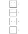
ピクチャ内をブロックに分割してイントラ予測(MODE_INTRA)及びインター予測(MODE_INTER)を行う場合、イントラ予測及びインター予測の方法を切り替える単位をより小さくするために、必要に応じて符号化ブロックを分割して予測を行う。この符号化ブロックの輝度信号と色差信号の分割方法を識別するモードを分割モード(PartMode)と定義する。さらに、この分割されたブロックを予測ブロックと定義する。図4に示すように、符号化ブロックの輝度信号の分割方法に応じて4種類の分割モード(PartMode)を定義する。符号化ブロックの輝度信号を分割せず1つの予測ブロックとみなしたもの(図4(a))の分割モード(PartMode)を2N×2N分割(PART_2Nx2N)、符号化ブロックの輝度信号を水平方向に2分割し、2つの予測ブロックとしたもの(図4(b))の分割モード(PartMode)を2N×N分割(PART_2NxN)、符号化ブロックの輝度信号を垂直方向に分割し、符号化ブロックを2つの予測ブロックとしたもの(図4(c))の分割モード(PartMode)をN×2N分割(PART_Nx2N)、符号化ブロックの輝度信号を水平と垂直の均等分割により4つの予測ブロックとしたもの(図4(d))の分割モード(PartMode)をN×N分割(PART_NxN)とそれぞれ定義する。なお、イントラ予測(MODE_INTRA)のN×N分割(PART_NxN)を除き、各分割モード(PartMode)毎に輝度信号の縦横の分割比率と同様に色差信号も分割する。
(About split mode, prediction block, prediction unit)
When performing intra prediction (MODE_INTRA) and inter prediction (MODE_INTER) by dividing the picture into blocks, the coded block is divided as necessary to reduce the unit for switching the intra prediction and inter prediction methods. Make predictions. A mode for identifying the division method of the luminance signal and the color difference signal of the coding block is defined as a division mode (PartMode). Furthermore, this divided block is defined as a prediction block. As shown in FIG. 4, four types of partition modes (PartMode) are defined according to the method of dividing the luminance signal of the coding block. The division mode (PartMode) of what is regarded as one prediction block without dividing the luminance signal of the coding block (FIG. 4A) is 2N × 2N division (PART_2Nx2N), and the luminance signal of the coding block is horizontally The division mode (PartMode) of the two prediction blocks (FIG. 4B) is divided into 2N × N divisions (PART_2NxN), the luminance signal of the encoded block is divided in the vertical direction, and the encoded block is The division mode (PartMode) of the two prediction blocks (FIG. 4 (c)) is N × 2N division (PART_Nx2N), and the luminance signal of the encoded block is divided into four prediction blocks by horizontal and vertical equal divisions. The division mode (PartMode) of (FIG. 4D) is defined as N × N division (PART_NxN), respectively. Except for N × N division (PART_NxN) of intra prediction (MODE_INTRA), the color difference signal is also divided for each division mode (PartMode) in the same manner as the vertical / horizontal division ratio of the luminance signal.
符号化ブロック内部において、各予測ブロックを特定する為に、0から開始する番号を、符号化順序で、符号化ブロック内部に存在する予測ブロックに対して割り当てる。この番号を分割インデックスPartIdxと定義する。図4の符号化ブロックの各予測ブロックの中に記述された数字は、その予測ブロックの分割インデックスPartIdxを表す。図4(b)に示す2N×N分割(PART_2NxN)では上の予測ブロックの分割インデックスPartIdxを0とし、下の予測ブロックの分割インデックスPartIdxを1とする。図4(c)に示すN×2N分割(PART_Nx2N)では左の予測ブロックの分割インデックスPartIdxを0とし、右の予測ブロックの分割インデックスPartIdxを1とする。図4(d)に示すN×N分割(PART_NxN)では、左上の予測ブロックの分割インデックスPartIdxを0とし、右上の予測ブロックの分割インデックスPartIdxを1とし、左下の予測ブロックの分割インデックスPartIdxを2とし、右下の予測ブロックの分割インデックスPartIdxを3とする。 In order to specify each prediction block within the coding block, a number starting from 0 is assigned to the prediction block existing inside the coding block in the coding order. This number is defined as a split index PartIdx. A number described in each prediction block of the encoded block in FIG. 4 represents a partition index PartIdx of the prediction block. In the 2N × N division (PART_2NxN) shown in FIG. 4B, the division index PartIdx of the upper prediction block is set to 0, and the division index PartIdx of the lower prediction block is set to 1. In the N × 2N division (PART_Nx2N) shown in FIG. 4C, the division index PartIdx of the left prediction block is set to 0, and the division index PartIdx of the right prediction block is set to 1. In the N × N partition (PART_NxN) shown in FIG. 4D, the partition index PartIdx of the upper left prediction block is 0, the partition index PartIdx of the upper right prediction block is 1, and the partition index PartIdx of the lower left prediction block is 2. And the division index PartIdx of the prediction block at the lower right is set to 3.
予測モード(PredMode)がインター予測(MODE_INTER)では、最小の符号化ブロックである符号化ブロックD以外では、分割モード(PartMode)は2N×2N分割(PART_2Nx2N)、2N×N分割(PART_2NxN)、及びN×2N分割(PART_Nx2N)を定義し、最小の符号化ブロックである符号化ブロックDのみ、分割モード(PartMode)は2N×2N分割(PART_2Nx2N)、2N×N分割(PART_2NxN)、及びN×2N分割(PART_Nx2N)に加えてN×N分割(PART_NxN)を定義する。なお、最小の符号化ブロック以外にN×N分割(PART_NxN)を定義しない理由は最小の符号化ブロック以外では、符号化ブロックを4分割して小さな符号化ブロックを表現できるからである。 When the prediction mode (PredMode) is inter prediction (MODE_INTER), except for the coding block D which is the smallest coding block, the partition mode (PartMode) is 2N × 2N partition (PART_2Nx2N), 2N × N partition (PART_2NxN), and N × 2N partition (PART_Nx2N) is defined, and only the coding block D which is the smallest coding block, the partition mode (PartMode) is 2N × 2N partition (PART_2Nx2N), 2N × N partition (PART_2NxN), and N × 2N In addition to the division (PART_Nx2N), N × N division (PART_NxN) is defined. The reason why N × N division (PART_NxN) is not defined other than the smallest coding block is that, except for the smallest coding block, the coding block can be divided into four to represent a small coding block.
(ツリーブロック、符号化ブロック、予測ブロック、変換ブロックの位置)
本実施の形態のツリーブロック、符号化ブロック、予測ブロック、変換ブロックを始めとする各ブロックの位置は、輝度信号の画面の一番左上の輝度信号の画素の位置を原点(0,0)とし、それぞれのブロックの領域に含まれる一番左上の輝度信号の画素の位置を(x,y)の二次元座標で表す。座標軸の向きは水平方向に右の方向、垂直方向に下の方向をそれぞれ正の向きとし、単位は輝度信号の1画素単位である。輝度信号と色差信号で画像サイズ(画素数)が同じである色差フォーマットが4:4:4の場合ではもちろんのこと、輝度信号と色差信号で画像サイズ(画素数)が異なる色差フォーマットが4:2:0、4:2:2の場合でも色差信号の各ブロックの位置をそのブロックの領域に含まれる輝度信号の画素の座標で表し、単位は輝度信号の1画素である。この様にすることで、色差信号の各ブロックの位置が特定できるのはもちろんのこと、座標の値を比較するだけで、輝度信号のブロックと色差信号のブロックの位置の関係も明確となる。
(Position of tree block, coding block, prediction block, transform block)
The position of each block including the tree block, the encoding block, the prediction block, and the transform block according to the present embodiment has the position of the pixel of the luminance signal at the upper left of the luminance signal screen as the origin (0, 0). The pixel position of the upper left luminance signal included in each block area is represented by two-dimensional coordinates (x, y). The direction of the coordinate axis is a right direction in the horizontal direction and a downward direction in the vertical direction, respectively, and the unit is one pixel unit of the luminance signal. Of course, the luminance signal and the color difference signal have the same image size (number of pixels) and the color difference format is 4: 4: 4. Of course, the luminance signal and the color difference signal have a different color size format of 4: 4. Even in the case of 2: 0, 4: 2: 2, the position of each block of the color difference signal is represented by the coordinates of the pixel of the luminance signal included in the block area, and the unit is one pixel of the luminance signal. In this way, not only can the position of each block of the color difference signal be specified, but also the relationship between the positions of the luminance signal block and the color difference signal block can be clarified only by comparing the coordinate values.
(インター予測モード、参照リスト、参照インデックスについて)
本発明の実施の形態においては、符号化または復号済みのピクチャの画像信号から予測を行うインター予測では、複数の復号済みのピクチャを参照ピクチャとして用いることができる。複数の参照ピクチャからインター予測に用いる参照ピクチャを特定するため、予測ブロック毎に参照インデックスで指定する。Bスライスでは予測ブロック毎に任意の2枚の参照ピクチャを選択してインター予測(動き補償予測)することができ、インター予測モードとしてL0予測(Pred_L0)、L1予測(Pred_L1)、双予測(Pred_BI)がある。参照ピクチャはリスト構造のL0(参照リスト0)とL1(参照リスト1)で管理され、L0またはL1の参照インデックスを指定することにより参照ピクチャを特定することができる。L0予測(Pred_L0)はL0で管理されている参照ピクチャを参照して予測画像信号を生成するインター予測であり、L1予測(Pred_L1)はL1で管理されている参照ピクチャを参照して予測画像信号を生成するインター予測であり、双予測(Pred_BI)はL0予測とL1予測が共に行われ、L0とL1のそれぞれで管理されている1つずつの参照ピクチャを参照して得られるL0予測画像信号とL1予測画像信号を平均または重み付け加算して予測画像信号を生成するインター予測である。Pスライスのインター予測ではL0予測(Pred_L0)のみが使用でき、Bスライスのインター予測ではL0予測(Pred_L0)、L1予測(Pred_L1)、および双予測(Pred_BI)が使用できる。L0予測、L1予測は1つの参照インデックスと1つの動きベクトルをインター予測情報として持ち、双予測は2つの参照インデックスと2つの動きベクトルをインター予測情報として持つ。以降の処理において出力に添え字LX(Xは0または1)が付いている定数、変数に関しては、L0、L1ごとに処理が行われることを前提とする。
(Inter prediction mode, reference list, reference index)
In the embodiment of the present invention, in inter prediction in which prediction is performed from an image signal of a coded or decoded picture, a plurality of decoded pictures can be used as reference pictures. In order to specify a reference picture used for inter prediction from a plurality of reference pictures, each prediction block is designated by a reference index. In the B slice, any two reference pictures can be selected for each prediction block and inter prediction (motion compensation prediction) can be performed. As inter prediction modes, L0 prediction (Pred_L0), L1 prediction (Pred_L1), and bi-prediction (Pred_BI) ) The reference picture is managed by L0 (reference list 0) and L1 (reference list 1) of the list structure, and the reference picture can be specified by specifying the reference index of L0 or L1. The L0 prediction (Pred_L0) is inter prediction that generates a predicted image signal with reference to a reference picture managed in L0, and the L1 prediction (Pred_L1) is a predicted image signal with reference to a reference picture managed in L1. The bi-prediction (Pred_BI) is an L0 prediction image signal obtained by referring to one reference picture managed by each of L0 and L1. And L1 prediction image signals are averaged or weighted and added to generate a prediction image signal. Only L0 prediction (Pred_L0) can be used for inter prediction of P slice, and L0 prediction (Pred_L0), L1 prediction (Pred_L1), and bi-prediction (Pred_BI) can be used for inter prediction of B slice. The L0 prediction and the L1 prediction have one reference index and one motion vector as inter prediction information, and the bi-prediction has two reference indexes and two motion vectors as inter prediction information. In the subsequent processing, regarding constants and variables with subscript LX (X is 0 or 1) in the output, it is assumed that processing is performed for each of L0 and L1.
(予測動きベクトル、差分動きベクトル、予測動きベクトルインデックスについて)
本発明の実施の形態においては、各予測ブロックで生成される動きベクトルの符号量を削減する為に、動きベクトルに対して予測処理が行われる。複数の予測動きベクトルの候補を導出し、それら予測動きベクトルの候補の中から1つの予測動きベクトルを選択し、符号化または復号対象の動きベクトルと選択された予測動きベクトルとの差分である差分動きベクトルを算出する。複数の予測動きベクトルからインター予測に用いる予測動きベクトルを特定するため、予測ブロック毎に予測動きベクトルインデックスで指定する。
(About predicted motion vectors, differential motion vectors, and predicted motion vector indexes)
In the embodiment of the present invention, in order to reduce the code amount of the motion vector generated in each prediction block, a prediction process is performed on the motion vector. A plurality of motion vector predictor candidates are derived, one motion vector predictor is selected from the motion vector predictor candidates, and a difference that is a difference between the motion vector to be encoded or decoded and the selected motion vector predictor A motion vector is calculated. In order to specify a prediction motion vector used for inter prediction from a plurality of prediction motion vectors, each prediction block is designated by a prediction motion vector index.
(マージモード、マージ候補)
マージモードとは、符号化または復号対象の予測ブロックの予測モード、参照インデックス、動きベクトル等のインター予測情報を符号化または復号するのではなく、符号化または復号対象の予測ブロックと同一ピクチャ内でその符号化または復号対象の予測ブロックに近接する予測ブロック、あるいは符号化または復号対象の予測ブロックと時間的に異なる符号化または復号済みのピクチャの符号化または復号対象の予測ブロックと同一位置あるいはその付近(近傍の位置)に存在する予測ブロックのインター予測情報から符号化または復号対象の予測ブロックのインター予測情報を導出することによりインター予測を行うモードである。符号化または復号対象の予測ブロックと同一ピクチャ内でその符号化または復号対象の予測ブロックに近接する予測ブロック及びその予測ブロックのインター予測情報を空間マージ候補、符号化または復号対象の予測ブロックと時間的に異なる符号化または復号済みのピクチャの符号化または復号対象の予測ブロックと同一位置あるいはその付近(近傍の位置)に存在する予測ブロック及びその予測ブロックのインター予測情報から導出されるインター予測情報を時間マージ候補とする。それぞれのマージ候補はマージ候補リストに登録され、マージインデックスによりインター予測で用いるマージ候補を特定する。導出されるインター予測情報はインター予測モード、各参照リストの参照インデックス及び動きベクトルである。
(Merge mode, merge candidate)
In the merge mode, the prediction mode of the prediction block to be encoded or decoded, the inter prediction information such as the reference index and the motion vector is not encoded or decoded, but within the same picture as the prediction block to be encoded or decoded. The prediction block adjacent to the prediction block to be encoded or decoded, or the same position as the prediction block to be encoded or decoded of the encoded or decoded picture that is temporally different from the prediction block to be encoded or decoded. In this mode, inter prediction is performed by deriving inter prediction information of a prediction block to be encoded or decoded from inter prediction information of a prediction block existing in the vicinity (neighboring position). A prediction block close to the prediction block to be encoded or decoded in the same picture as the prediction block to be encoded or decoded and inter prediction information of the prediction block are spatial merge candidates, a prediction block to be encoded or decoded, and time Prediction information derived from a prediction block existing at the same position as or near (previously near) a prediction block to be encoded or decoded of a differently encoded or decoded picture and inter prediction information of the prediction block Are time merge candidates. Each merge candidate is registered in the merge candidate list, and the merge candidate used in the inter prediction is specified by the merge index. The derived inter prediction information includes an inter prediction mode, a reference index of each reference list, and a motion vector.
(近接する予測ブロックについて)
図5、図6、図7及び図8は符号化または復号対象の予測ブロックと同一ピクチャ内でその符号化または復号対象の予測ブロックに近接する予測ブロックを説明する図である。図9は符号化または復号対象の予測ブロックと時間的に異なる符号化または復号済みのピクチャにおいて、符号化または復号対象の予測ブロックと同一位置あるいはその付近に存在する既に符号化または復号済みの予測ブロックを説明する図である。図5、図6、図7、図8及び図9を用いて符号化または復号対象の予測ブロックの空間方向に近接する予測ブロック、及び異なる時間の同一位置の予測ブロックについて説明する。
(About adjacent prediction blocks)
5, FIG. 6, FIG. 7 and FIG. 8 are diagrams for explaining a prediction block close to the prediction block to be encoded or decoded in the same picture as the prediction block to be encoded or decoded. FIG. 9 shows an already encoded or decoded prediction existing in the same position as or near the prediction block to be encoded or decoded in a picture that has been encoded or decoded that differs in time from the prediction block to be encoded or decoded. It is a figure explaining a block. A prediction block that is close in the spatial direction of a prediction block to be encoded or decoded and a prediction block at the same position at different times will be described with reference to FIGS. 5, 6, 7, 8, and 9.
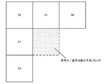
図5に示すように、符号化または復号対象の予測ブロックと同一ピクチャ内でその符号化または復号対象の予測ブロックの左側の辺に近接する予測ブロックA1、上側の辺に近接する予測ブロックB1、右上の頂点に近接する予測ブロックB0、左下の頂点に近接する予測ブロックA0、および左上の頂点に近接する予測ブロックB2を空間方向に近接する予測ブロックと定義する。 As shown in FIG. 5, in the same picture as the prediction block to be encoded or decoded, a prediction block A1 close to the left side of the prediction block to be encoded or decoded, prediction block B1 close to the upper side, The prediction block B0 close to the top right vertex, the prediction block A0 close to the bottom left vertex, and the prediction block B2 close to the top left vertex are defined as prediction blocks close to the spatial direction.
なお、図6に示すように、符号化または復号対象の予測ブロックの左側の辺に近接する予測ブロックのサイズが符号化または復号対象の予測ブロックより小さく、複数存在する場合には、本実施の形態においては左側の辺に近接する予測ブロックの中で最も下の予測ブロックA10だけを左側の辺に近接する予測ブロックA1とする。 As shown in FIG. 6, when the size of the prediction block adjacent to the left side of the prediction block to be encoded or decoded is smaller than the prediction block to be encoded or decoded and there are a plurality of prediction blocks, this embodiment In the embodiment, only the lowest prediction block A10 among the prediction blocks adjacent to the left side is set as the prediction block A1 adjacent to the left side.
同様に、符号化または復号対象の予測ブロックの上側の辺に近接する予測ブロックのサイズが符号化または復号対象の予測ブロックより小さく、複数存在する場合には、本実施の形態においては左側の辺に近接する予測ブロックの中で最も右の予測ブロックB10だけを上側の辺に近接する予測ブロックB1とする。 Similarly, when the size of the prediction block adjacent to the upper side of the prediction block to be encoded or decoded is smaller than the prediction block to be encoded or decoded and there are a plurality of prediction blocks, the left side in the present embodiment Only the rightmost prediction block B10 in the prediction blocks close to is set as the prediction block B1 close to the upper side.
なお、図7に示すように、符号化または復号対象の予測ブロックの左側に近接する予測ブロックAのサイズが符号化または復号対象の予測ブロックより大きい場合にも、前記条件に従い、左側に近接する予測ブロックAがその符号化または復号対象の予測ブロックの左側の辺に近接していれば予測ブロックA1とし、符号化または復号対象の予測ブロックの左下の頂点に近接していれば予測ブロックA0とし、符号化または復号対象の予測ブロックの左上の頂点に近接していれば予測ブロックB2とする。図6の例では、予測ブロックA0、予測ブロックA1及び予測ブロックB2は同一の予測ブロックとなる。 In addition, as shown in FIG. 7, even when the size of the prediction block A adjacent to the left side of the prediction block to be encoded or decoded is larger than the prediction block to be encoded or decoded, it is close to the left side according to the above condition. If the prediction block A is close to the left side of the prediction block to be encoded or decoded, the prediction block A1 is used. If the prediction block A is close to the lower left vertex of the prediction block to be encoded or decoded, the prediction block A0 is set. If it is close to the upper left vertex of the prediction block to be encoded or decoded, the prediction block is B2. In the example of FIG. 6, the prediction block A0, the prediction block A1, and the prediction block B2 are the same prediction block.
なお、図8に示すように、符号化または復号対象の予測ブロックの上側に近接する予測ブロックBのサイズが符号化または復号対象の予測ブロックより大きい場合にも、前記条件に従い、上側に近接する予測ブロックBがその符号化または復号対象の予測ブロックの上側の辺に近接していれば予測ブロックB1とし、符号化または復号対象の予測ブロックの右上の頂点に近接していれば予測ブロックB0とし、符号化または復号対象の予測ブロックの左上の頂点に近接していれば予測ブロックB2とする。図8の例では、予測ブロックB0、予測ブロックB1及び予測ブロックB2は同一の予測ブロックとなる。 As shown in FIG. 8, even when the size of the prediction block B adjacent to the upper side of the prediction block to be encoded or decoded is larger than the prediction block to be encoded or decoded, the size is close to the upper side according to the above condition. If the prediction block B is close to the upper side of the prediction block to be encoded or decoded, the prediction block B1 is set. If the prediction block B is close to the upper right vertex of the prediction block to be encoded or decoded, the prediction block B0 is set. If it is close to the upper left vertex of the prediction block to be encoded or decoded, the prediction block is B2. In the example of FIG. 8, the prediction block B0, the prediction block B1, and the prediction block B2 are the same prediction block.
図9に示すように、符号化または復号対象の予測ブロックと時間的に異なる符号化または復号済みのピクチャにおいて、符号化または復号対象の予測ブロックと同一位置あるいはその付近に存在する既に符号化または復号済みの予測ブロックT0およびT1を異なる時間の同一位置の予測ブロックと定義する。 As shown in FIG. 9, in a picture that has been encoded or decoded that is temporally different from the prediction block to be encoded or decoded, already encoded or existing at the same position as or near the prediction block to be encoded or decoded. The decoded prediction blocks T0 and T1 are defined as prediction blocks at the same position at different times.
(予測ブロックグループについて)
複数の予測ブロックで構成されるグループを予測ブロックグループと定義する。図5に示す符号化または復号対象の予測ブロックと同一ピクチャ内でその符号化または復号対象の予測ブロックの左側の辺に近接する予測ブロックA1、および符号化または復号対象の予測ブロックの左下の頂点に近接する予測ブロックA0で構成される第1の予測ブロックグループを左側に近接する予測ブロックグループと定義する。
(About prediction block groups)
A group composed of a plurality of prediction blocks is defined as a prediction block group. The prediction block A1 close to the left side of the prediction block to be encoded or decoded in the same picture as the prediction block to be encoded or decoded shown in FIG. 5, and the lower left vertex of the prediction block to be encoded or decoded Is defined as a prediction block group adjacent to the left side.
図5に示す符号化または復号対象の予測ブロックと同一ピクチャ内でその符号化または復号対象の予測ブロックの上側の辺に近接する予測ブロックB1、符号化または復号対象の予測ブロックの右上の頂点に近接する予測ブロックB0、および符号化または復号対象の予測ブロックの左上の頂点に近接する予測ブロックB2で構成される第2の予測ブロックグループを上側に近接する予測ブロックグループと定義する。 In the same picture as the prediction block to be encoded or decoded shown in FIG. 5, the prediction block B1 close to the upper side of the prediction block to be encoded or decoded, and the upper right vertex of the prediction block to be encoded or decoded A second prediction block group including a prediction block B0 that is close and a prediction block B2 that is close to the top left vertex of the prediction block to be encoded or decoded is defined as a prediction block group that is close to the upper side.
図9に示す符号化または復号対象の予測ブロックと時間的に異なる符号化または復号済みのピクチャにおいて、符号化または復号対象の予測ブロックと同一位置あるいはその近傍の位置に存在する既に符号化または復号済みの予測ブロックグループT0およびT1で構成される第3の予測ブロックグループを異なる時間の予測ブロックグループと定義する。 In a picture that has been encoded or decoded that is temporally different from the prediction block to be encoded or decoded shown in FIG. 9, already encoded or decoded at the same position as or near the prediction block to be encoded or decoded A third prediction block group composed of already-predicted prediction block groups T0 and T1 is defined as a prediction block group at different times.
(POCについて)
POCは符号化されるピクチャに関連付けられる変数とし、ピクチャの出力/表示順序で1ずつ増加する値が設定される。POCの値によって、同じピクチャであるかを判別したり、出力/表示順序でのピクチャ間の前後関係を判別したり、ピクチャ間の距離を導出したりすることができる。例えば、2つのピクチャのPOCが同じ値を持つ場合、同一のピクチャであると判断できる。2つのピクチャのPOCが違う値を持つ場合、POCの値が小さいピクチャのほうが、時間的に先に出力/表示されるピクチャであると判断でき、2つのピクチャのPOCの差が時間軸方向でのピクチャ間距離を示す。
(About POC)
POC is a variable associated with the picture to be encoded, and is set to a value that increases by 1 in the picture output / display order. Based on the POC value, it is possible to determine whether they are the same picture, to determine the front-to-back relationship between pictures in the output / display order, or to derive the distance between pictures. For example, if the POCs of two pictures have the same value, it can be determined that they are the same picture. When the POCs of two pictures have different values, it can be determined that the picture with the smaller POC value is a picture that is output / displayed earlier in time, and the difference between the POCs of the two pictures is the time axis direction. Indicates the distance between pictures.
本発明の実施の形態における動画像符号化装置、動画像符号化方法、動画像符号化プログラム、動画像復号装置、動画像復号方法、動画像復号プログラムにおいては、スライス単位、または予測ブロックのサイズに応じて、インター予測モードが双予測(Pred_BI)の場合に、L0またはL1のいずれか一方のインター予測情報の符号化または復号を行うかどうかを切り替える。切り替える対象となるインター予測情報は差分動きベクトル、参照インデックス、予測動きベクトルインデックスの一部、またはすべてである。 In the moving image encoding device, the moving image encoding method, the moving image encoding program, the moving image decoding device, the moving image decoding method, and the moving image decoding program according to the embodiment of the present invention, the size of the slice unit or the prediction block Accordingly, when the inter prediction mode is bi-prediction (Pred_BI), whether to encode or decode either L0 or L1 inter prediction information is switched. The inter prediction information to be switched is a difference motion vector, a reference index, a part or all of a prediction motion vector index.
インター予測モードが双予測(Pred_BI)の場合、L0およびL1の2つの動きベクトルを利用してインター予測するので、1つの動きベクトルのみを利用するL0予測やL1予測に比べて、動きベクトルを符号化するのに多くの符号量を必要とする。動きベクトルを符号化する際には符号量を削減するために差分動きベクトルを導出し、その導出された差分動きベクトルが符号化される。双予測の場合において、L0またはL1の動きベクトルに対応する差分動きベクトルの一方の符号化を行わず、差分動きベクトルの値を(0,0)とすることで、インター予測情報の符号量を削減する。ただし、双予測においてL0またはL1のいずれか一方の差分動きベクトルの値を(0,0)とすることで、予測動きベクトルの値がそのまま動きベクトルとなり、任意の動きベクトルを利用することができないので残差信号の符号量が増加することがある。したがって、本実施の形態においては、双予測においてL0またはL1の動きベクトルに対応する動きベクトルの一方を予測動きベクトルと同じ値に設定しても残差信号の符号量が増加しにくく、全体としての符号量が減少しやすい状況ではL0またはL1の動きベクトルに対応する差分動きベクトルの一方の符号化を行わないこととし、双予測においてL0またはL1の動きベクトルに対応する動きベクトルの一方を予測動きベクトルと同じ値に設定すると残差信号の符号量が増加しやすく、全体としての符号量が増加しやすい状況ではL0およびL1の動きベクトルに対応する差分動きベクトルをそれぞれ符号化する。 When the inter prediction mode is bi-prediction (Pred_BI), since inter prediction is performed using two motion vectors of L0 and L1, a motion vector is encoded as compared with L0 prediction and L1 prediction using only one motion vector. Requires a large amount of code. When encoding a motion vector, a differential motion vector is derived in order to reduce the amount of code, and the derived differential motion vector is encoded. In the case of bi-prediction, coding of one of the differential motion vectors corresponding to the L0 or L1 motion vector is not performed, and the value of the differential motion vector is set to (0, 0). Reduce. However, in bi-prediction, by setting the value of one of the difference motion vectors of L0 or L1 to (0, 0), the value of the predicted motion vector becomes the motion vector as it is, and an arbitrary motion vector cannot be used. Therefore, the code amount of the residual signal may increase. Therefore, in this embodiment, even if one of the motion vectors corresponding to the L0 or L1 motion vector is set to the same value as the predicted motion vector in bi-prediction, the code amount of the residual signal is unlikely to increase. In a situation where the amount of code of L is likely to decrease, one of the differential motion vectors corresponding to the L0 or L1 motion vector is not encoded, and one of the motion vectors corresponding to the L0 or L1 motion vector is predicted in bi-prediction If it is set to the same value as the motion vector, the code amount of the residual signal is likely to increase, and in a situation where the overall code amount is likely to increase, the differential motion vectors corresponding to the L0 and L1 motion vectors are encoded.
本実施の形態においては、第1の方法として、予測ブロックのサイズに応じて、インター予測モードが双予測(Pred_BI)の場合に、L0またはL1のいずれか一方の差分動きベクトルの符号化または復号を行うかどうかを切り替える。予測ブロックのサイズが小さい場合はL0またはL1のいずれか一方の差分動きベクトルの符号化または復号を行わず、予測ブロックのサイズが大きい場合はL0およびL1の双方の差分動きベクトルの符号化または復号を行う。予測ブロックのサイズが小さい場合は、画素数が少ないため、予測ブロックあたりの残差信号の符号量も小さい。したがって、双予測において差分動きベクトルの一方の符号化を行わなくても残差信号の符号量が増加しにくく、全体としての符号量が減少する。一方、予測ブロックのサイズが大きい場合は、画素数が多いため、予測ブロックあたりの残差信号の符号量も大きい。したがって、双予測において差分動きベクトルの一方の符号化を行わないと残差信号の符号量が増加しやすく、全体としての符号量が増加する。 In the present embodiment, as a first method, depending on the size of the prediction block, when the inter prediction mode is bi-prediction (Pred_BI), encoding or decoding of either L0 or L1 differential motion vector Switch whether to do. When the predicted block size is small, either the L0 or L1 differential motion vector is not encoded or decoded, and when the predicted block size is large, both the L0 and L1 differential motion vectors are encoded or decoded. I do. When the size of the prediction block is small, the number of pixels is small, so the code amount of the residual signal per prediction block is also small. Therefore, even if one of the differential motion vectors is not encoded in bi-prediction, the code amount of the residual signal is difficult to increase, and the code amount as a whole decreases. On the other hand, when the size of the prediction block is large, since the number of pixels is large, the code amount of the residual signal per prediction block is also large. Therefore, if one of the differential motion vectors is not encoded in bi-prediction, the code amount of the residual signal is likely to increase, and the code amount as a whole increases.
また、本実施の形態においては、第2の方法として、スライス毎に、インター予測モードが双予測(Pred_BI)の場合に、L0またはL1のいずれか一方の差分動きベクトルの符号化または復号を行うかどうかを切り替える。 In the present embodiment, as the second method, for each slice, when the inter prediction mode is bi-prediction (Pred_BI), either differential motion vector of L0 or L1 is encoded or decoded. To switch.
例えば、L0とL1で同一の参照画像を含むスライスや、L0とL1を共に時間方向で符号化または復号対象ピクチャよりも前の参照ピクチャを参照する前方向予測として利用し、時間方向で符号化または復号対象ピクチャよりも後ろの参照ピクチャを参照する後方向予測を含まないスライスでは、L0またはL1のいずれか一方を動きベクトルにより検出される動きベクトルの代わりに予測動きベクトルを用いても予測精度が低下しにくく残差成分の符号量の増加量が小さいため、差分動きベクトルの符号量を削減するために、L0またはL1のいずれか一方の差分動きベクトルの符号化または復号を行わない。 For example, a slice including the same reference image in L0 and L1, or both L0 and L1 are encoded in the temporal direction, or used as forward prediction to refer to a reference picture before the decoding target picture, and encoded in the temporal direction. Alternatively, in a slice that does not include backward prediction that refers to a reference picture after the picture to be decoded, even if one of L0 and L1 is used instead of the motion vector detected by the motion vector, the prediction accuracy is used. Since the amount of increase in the code amount of the residual component is small, the difference motion vector of either L0 or L1 is not encoded or decoded in order to reduce the code amount of the difference motion vector.
L0とL1で同一の参照画像を含まないスライスや、L0を前方向予測、L1を後方向予測として用いるスライスでは、L0またはL1のいずれか一方を動きベクトルにより検出される動きベクトルの代わりに予測動きベクトルを用いると予測精度が低下して残差成分の符号量の増加量が大きいため、予測精度を高めて残差成分の符号量を削減するために、L0およびL1の双方の差分動きベクトルの符号化または復号を行う。 For slices that do not include the same reference image in L0 and L1, or slices that use L0 as forward prediction and L1 as backward prediction, predict either L0 or L1 instead of the motion vector detected by the motion vector. If a motion vector is used, the prediction accuracy decreases and the amount of increase in the residual component code amount is large. Therefore, in order to increase the prediction accuracy and reduce the residual component code amount, the difference motion vectors of both L0 and L1 are used. Is encoded or decoded.
また、差分動きベクトルと同様の理由により、スライス単位、または予測ブロックのサイズに応じて、双予測においてL0またはL1のいずれか一方の参照インデックスも符号化または復号を行うかどうかを切り替えることができる。インター予測情報の符号量が大きくなる双予測の場合において、L0およびL1の動きベクトルに対応する参照インデックスの一方の符号化を行わず、参照インデックスの値を導出するかどうかをデフォルト値に設定することで、インター予測情報の符号量を削減する。ただし、双予測においてL0またはL1のいずれか一方の参照インデックスの値を導出するかどうかをデフォルト値に設定することで、任意の参照ピクチャを利用することができないので残差信号の符号量が増加することがある。したがって、本実施の形態においては、双予測においてL0またはL1のいずれか一方の参照インデックスの値を導出するかデフォルト値に設定しても残差信号の符号量が増加しにくく、全体としての符号量が減少しやすい状況ではL0またはL1の参照インデックスの一方の符号化を行わないこととし、双予測においてL0またはL1のいずれか一方の参照インデックスの値を導出するかデフォルト値に設定すると残差信号の符号量が増加しやすく、全体としての符号量が増加しやすい状況ではL0およびL1の参照インデックスを共に符号化する。 Also, for the same reason as the difference motion vector, it is possible to switch whether or not the reference index of either L0 or L1 is also encoded or decoded in bi-prediction according to the slice unit or the size of the prediction block. . In the case of bi-prediction in which the code amount of inter prediction information is large, one of the reference indexes corresponding to the L0 and L1 motion vectors is not encoded, and whether or not the reference index value is derived is set as a default value. Thus, the code amount of the inter prediction information is reduced. However, by setting whether to derive the reference index value of either L0 or L1 in the bi-prediction as a default value, an arbitrary reference picture cannot be used, so the code amount of the residual signal increases. There are things to do. Therefore, in this embodiment, even if the value of one of the reference indexes of L0 or L1 is derived or set to the default value in bi-prediction, the code amount of the residual signal hardly increases, and the code as a whole In a situation where the amount is likely to decrease, one of the L0 or L1 reference indexes is not encoded, and if bi-prediction derives the value of either the L0 or L1 reference index or sets the default value, the residual In a situation where the code amount of the signal is likely to increase and the code amount as a whole is likely to increase, both the L0 and L1 reference indexes are encoded.
また、差分動きベクトル、参照インデックスと同様の理由により、スライス単位、または予測ブロックのサイズに応じて、双予測においてL0またはL1のいずれか一方の差分予測ベクトルインデックスも符号化または復号を行うかどうかを切り替えることができる。インター予測情報の符号量が大きくなる双予測の場合において、L0またはL1の動きベクトルに対応する予測ベクトルインデックスの一方の符号化を行わず、予測ベクトルインデックスの値を他方の予測ベクトルインデックスと同じ値に設定することで、インター予測情報の符号量を削減する。ただし、双予測においてL0またはL1のいずれか一方の予測ベクトルインデックスの値を他方の予測ベクトルインデックスと同じ値とすることで、任意の予測ベクトルインデックスを利用することができないので残差信号の符号量が増加することがある。したがって、本実施の形態においては、双予測においてL0またはL1のいずれか一方の予測ベクトルインデックスの値を他方の予測ベクトルインデックスと同じ値に設定しても残差信号の符号量が増加しにくく、全体としての符号量が減少しやすい状況ではL0またはL1の予測ベクトルインデックスの一方の符号化を行わないこととし、双予測においてL0またはL1のいずれか一方の予測ベクトルインデックスの値を他方の予測ベクトルインデックスと同じ値に設定すると残差信号の符号量が増加しやすく、全体としての符号量が増加しやすい状況ではL0およびL1の予測ベクトルインデックスを共に符号化する。 Also, for the same reason as the difference motion vector and the reference index, whether or not to encode or decode either the L0 or L1 difference prediction vector index in bi-prediction according to the slice unit or the size of the prediction block Can be switched. In the case of bi-prediction in which the code amount of inter prediction information is large, one of the prediction vector indexes corresponding to the motion vector of L0 or L1 is not encoded, and the value of the prediction vector index is the same value as the other prediction vector index By setting to, the code amount of inter prediction information is reduced. However, since the prediction vector index value of either L0 or L1 is set to the same value as the other prediction vector index in bi-prediction, an arbitrary prediction vector index cannot be used. May increase. Therefore, in the present embodiment, even if the value of one of the prediction vector indexes of L0 or L1 is set to the same value as the other prediction vector index in bi-prediction, the code amount of the residual signal is unlikely to increase. In a situation where the overall code amount is likely to decrease, one of the L0 or L1 prediction vector indexes is not encoded, and in bi-prediction, the value of one of the L0 or L1 prediction vector indexes is used as the other prediction vector. When the same value as the index is set, the code amount of the residual signal is likely to increase, and in a situation where the code amount as a whole is likely to increase, both the L0 and L1 prediction vector indexes are encoded.
以下の説明においては、スライス単位、または予測ブロックのサイズに応じて、インター予測モードが双予測(Pred_BI)の場合における、L0またはL1のいずれか一方のインター予測の符号化または復号を行うかどうかの切り替えに際しては、インター予測情報である差分動きベクトル、参照インデックス、予測動きベクトルインデックスのすべてを切り替えるものとして説明するが、すべてを切り替える場合に限定されず、差分動きベクトル、参照インデックス、予測動きベクトルインデックスの一部、すなわちいずれか1つまたは2つだけを切り替えることもできる。例えば、L0またはL1のいずれか一方の予測動きベクトルだけを符号化または復号を行うかどうかを切り替えて、L0およびL1の両方の参照インデックス、予測動きベクトルインデックスを符号化または復号してもよいし、L0またはL1のいずれか一方の予測動きベクトルおよび参照インデックスを符号化または復号を行うかどうかを切り替えて、L0およびL1の両方の予測動きベクトルインデックスを符号化または復号してもよい。 In the following description, whether to perform inter prediction encoding or decoding of either L0 or L1 when the inter prediction mode is bi-prediction (Pred_BI) according to the slice unit or the size of the prediction block. However, the present invention is not limited to switching all of the inter-prediction information, that is, the differential motion vector, the reference index, and the prediction motion vector index. It is also possible to switch only part of the index, ie only one or two. For example, it is possible to encode or decode both the L0 and L1 reference indexes and the prediction motion vector index by switching whether to encode or decode only one of the L0 and L1 prediction motion vectors. The prediction motion vector and the reference index of either L0 or L1 may be switched to encode or decode, and the prediction motion vector index of both L0 and L1 may be encoded or decoded.
また、以下の説明においては、スライス単位、または予測ブロックのサイズに応じて、インター予測モードが双予測(Pred_BI)の場合における、L1のインター予測の符号化または復号を行うかどうかを切り替えるものとして説明するが、L1に限定されず、L0のインター予測の符号化または復号を行うかどうかを切り替えることもできる。 Also, in the following description, it is assumed that whether to perform encoding or decoding of L1 inter prediction when the inter prediction mode is bi-prediction (Pred_BI) according to the slice unit or the size of the prediction block. As will be described, the present invention is not limited to L1, and it is also possible to switch whether to perform encoding or decoding of L0 inter prediction.
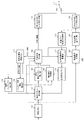
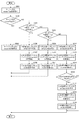
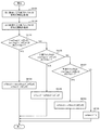
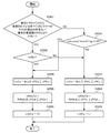
以下、図面と共に本発明の実施の形態を説明する。図1は本発明の実施の形態に係る動画像符号化装置100の構成を示すブロック図である。実施の形態の動画像符号化装置は、画像メモリ101、参照インデックス導出部116、動きベクトル検出部102、差分動きベクトル導出部103、インター予測情報推定部104、動き補償予測部105、予測方法決定部106、残差信号生成部107、直交変換・量子化部108、第1の符号化ビット列生成部109、第2の符号化ビット列生成部110、多重化部111、逆量子化・逆直交変換部112、復号画像信号重畳部113、符号化情報格納メモリ114、および復号画像メモリ115を備える。
Hereinafter, embodiments of the present invention will be described with reference to the drawings. FIG. 1 is a block diagram showing a configuration of a moving
本実施の形態においては、インター予測モードが双予測において、スライス毎、または符号化対象の予測ブロックのサイズに応じて、L1予測のインター予測情報を符号化するかどうかを切り替える。切り替える対象となるインター予測情報は参照インデックス、予測動きベクトルインデックス、差分動きベクトルの一部、またはすべてである。そこで、実施の形態の動画像符号化装置100では、双予測においてL1のインター予測情報が符号化されるかどうかを示すフラグinterInfoCodingL1Flagが0または1に設定される。フラグinterInfoCodingL1Flagが1は双予測においてL1のインター予測情報が符号化されることを示し、フラグinterInfoCodingL1Flagが0は双予測においてL1のインター予測情報が符号化されないことを示す。双予測においてL1のインター予測情報が符号化されるかどうかを示すフラグinterInfoCodingL1Flagは参照インデックス導出部116、動きベクトル検出部102、差分動きベクトル導出部103、動き補償予測部105、予測方法決定部106、第1の符号化ビット列生成部109で参照される。
In the present embodiment, when the inter prediction mode is bi-prediction, whether to encode inter prediction information for L1 prediction is switched for each slice or according to the size of a prediction block to be encoded. The inter prediction information to be switched is a reference index, a prediction motion vector index, a part of or all of a difference motion vector. Therefore, in the
画像メモリ101は、撮影/表示時間順に供給された符号化対象のピクチャの画像信号を一時格納する。画像メモリ101は、格納された符号化対象のピクチャの画像信号を、所定の画素ブロック単位で、動きベクトル検出部102、予測方法決定部106、および残差信号生成部107に供給する。その際、撮影/表示時間順に格納されたピクチャの画像信号は、符号化順序に並べ替えられて、画素ブロック単位で、画像メモリ101から出力される。
The
本実施の形態においては、インター予測モードが双予測において、スライス毎、または符号化対象の予測ブロックのサイズに応じて、L1予測のインター予測情報を符号化するかどうかを切り替える。切り替える対象となるインター予測情報として双予測でのL1の参照インデックスが含まれる場合で、双予測でのL1の参照インデックスを符号化しない場合、参照インデックス導出部116は、双予測でのL1の参照インデックスを導出し、動きベクトル検出部102、予測方法決定部106に供給する。符号化情報格納メモリに格納されている近接する予測ブロックのL1の参照インデックスを含む符号化情報を利用して、符号化対象の予測ブロックのL1の参照インデックスを導出してもよいし、L0の参照インデックスに対応するL0の参照ピクチャがL1にも含まれている場合にL1でも同じ参照ピクチャを用いることとし、その参照ピクチャに対応するL1の参照インデックスを導出してもよい。
In the present embodiment, when the inter prediction mode is bi-prediction, whether to encode inter prediction information for L1 prediction is switched for each slice or according to the size of a prediction block to be encoded. When the L1 reference index in bi-prediction is included as the inter prediction information to be switched, and the L1 reference index in bi-prediction is not encoded, the reference
動きベクトル検出部102は、画像メモリ101から供給される画像信号と復号画像メモリ115から供給される参照ピクチャ間でブロックマッチング等により各予測ブロックサイズ、および各インター予測モードでの、L0及びL1の各参照インデックス毎のそれぞれの動きベクトルを各予測ブロック単位で検出し、検出された動きベクトルを動き補償予測部105、差分動きベクトル導出部103、および予測方法決定部106に供給する。
The motion
インター予測が双予測においては、L0予測及びL1予測のために検出したそれぞれの動きベクトルを組み合わせて双予測の動きベクトルとしてもよいし、双予測のために別途動きベクトルを検出してもよい。 When the inter prediction is bi-prediction, the motion vectors detected for L0 prediction and L1 prediction may be combined into a motion vector for bi-prediction, or a separate motion vector may be detected for bi-prediction.
なお、本実施の形態においては、インター予測モードが双予測において、スライス毎、または符号化対象の予測ブロックのサイズに応じて、L1のインター予測情報を符号化するかどうかを切り替える。切り替える対象となるインター予測情報として双予測でのL1の差分動きベクトルが含まれる場合で、L1の差分動きベクトルを符号化しない場合、後述する方法によりL1の予測動きベクトルを導出し、その予測動きベクトルを双予測でのL1の動きベクトルとする。 In the present embodiment, when the inter prediction mode is bi-prediction, whether to encode L1 inter prediction information is switched for each slice or according to the size of the prediction block to be encoded. When the L1 differential motion vector in bi-prediction is included as the inter prediction information to be switched, and the L1 differential motion vector is not encoded, the L1 predicted motion vector is derived by the method described later, and the predicted motion Let the vector be the L1 motion vector in bi-prediction.
さらに、切り替える対象となるインター予測情報として双予測でのL1の参照インデックスが含まれる場合で、L1の参照インデックスを符号化しない場合、L1の参照インデックスの値を導出するかデフォルト値とする。 Further, when the L1 reference index in bi-prediction is included as the inter prediction information to be switched and the L1 reference index is not encoded, the value of the L1 reference index is derived or set as a default value.
差分動きベクトル導出部103は、符号化情報格納メモリ114に記憶されている既に符号化された画像信号の符号化情報を用いて、複数の予測動きベクトルの候補を算出して後述する予測動きベクトルリストに登録し、予測動きベクトルリストに登録された複数の予測動きベクトルの候補の中から最適な予測動きベクトルを選択し、動きベクトル検出部102が検出した動きベクトルと予測動きベクトルから差分動きベクトルを算出し、算出された差分動きベクトルを予測方法決定部106に供給する。なお、本実施の形態においては、インター予測モードが双予測において、スライス毎、または符号化対象の予測ブロックのサイズに応じて、L1のインター予測情報を符号化するかどうかを切り替える。切り替える対象となるインター予測情報として双予測でのL1の差分動きベクトルが含まれる場合で、双予測でのL1の差分動きベクトルを符号化しない場合、差分動きベクトルを(0,0)とする。さらに、予測動きベクトルリストに登録された予測動きベクトルの候補から選択された予測動きベクトルを特定する予測動きベクトルインデックスを予測方法決定部106に供給する。差分動きベクトル導出部103の詳細な構成と動作は後述する。
The differential motion
インター予測情報推定部104は、マージモードのインター予測情報を推定する。マージモードとは、当該予測ブロックの予測モード、参照インデックス(参照リストに登録されている複数の参照ピクチャから動き補償予測に利用する参照ピクチャを特定するための情報)、動きベクトル等のインター予測情報を符号化するのではなく、符号化済みの近接するインター予測された予測ブロック、あるいは異なるピクチャのインター予測された予測ブロックのインター予測情報を利用するモードである。符号化情報格納メモリ114に記憶されている既に符号化された予測ブロックの符号化情報を用いて、複数のマージの候補(インター予測情報の候補)を算出してマージ候補リストに登録し、マージ候補リストに登録された複数のマージ候補の中から最適なマージ候補を選択し、選択されたマージ候補の予測モード、参照インデックス、動きベクトル等のインター予測情報を動き補償予測部105に供給するとともに、選択されたマージ候補を特定するマージインデックスを予測方法決定部106に供給する。
The inter prediction
動き補償予測部105は、動きベクトル検出部102およびインター予測情報推定部104により検出された動きベクトルを用いて参照ピクチャから動き補償予測により予測画像信号を生成し、予測画像信号を予測方法決定部106に供給する。なお、L0予測、及びL1予測では、片方向の予測を行う。双予測(Pred_BI)の場合は、双方向の予測を行い、L0予測、L1予測のそれぞれのインター予測された信号に適応的に重み係数を掛け算し、オフセット値を加算して重畳し、最終的な予測画像信号を生成する。
The motion
予測方法決定部106は予測方法を決定する。それぞれの予測モードごとに符号量と符号化歪を算出し、最も少ない発生符号量と符号化歪となる予測ブロックサイズと予測モードが決定される。インター予測情報やイントラ予測情報等の符号化情報の符号量を算出する。さらに、動き補償予測部105から供給される予測画像信号と、画像メモリ101から供給される符号化対象の画像信号との予測残差信号を符号化した予測残差信号の符号量を算出する。動き情報の符号量と予測残差信号の符号量とが加算された総発生符号量を算出し、第1の評価値とする。尚、ここで算出される発生符号量は、符号化過程をシミュレートしたものであることが望ましいが、簡便に近似したり、概算することも可能である。
The prediction
また、こうした予測残差信号を符号化後に、歪量評価の為に復号し、符号化により生じる元の画像信号との誤差を表す比率として符号化歪が算出される。これら総発生符号量と符号化歪とを予測方法毎に比較することで、最も少ない発生符号量と符号化歪となる予測方法が決定される。 Further, after encoding such a prediction residual signal, it is decoded for distortion amount evaluation, and the encoding distortion is calculated as a ratio representing an error from the original image signal caused by the encoding. By comparing the total generated code amount and the coding distortion for each prediction method, a prediction method with the least generated code amount and the coding distortion is determined.
複数の予測方法の中から、最適な符号化ブロック単位でインター予測(PRED_INTER)かイントラ予測(PRED_INTRA)かを判別する予測モードPredMode、分割モードPartModeを決定し、インター予測(PRED_INTER)では予測ブロック単位でマージモードか否か等の予測方法を決定し、マージモードの場合はマージインデックス、マージモードでない場合はインター予測フラグ、予測動きベクトルインデックス、L0、L1の参照インデックス、差分動きベクトル等を決定して、決定に応じた符号化情報を第1の符号化ビット列生成部109に供給する。
PredMode that determines whether inter prediction (PRED_INTER) or intra prediction (PRED_INTRA) is optimized for each coding block among multiple prediction methods, determines the partition mode PartMode, and predictive block units for inter prediction (PRED_INTER) In the merge mode, a merge index is determined. In the merge mode, an inter prediction flag, a prediction motion vector index, a reference index of L0 and L1, a difference motion vector, and the like are determined. Thus, the encoded information corresponding to the determination is supplied to the first encoded bit
さらに、予測方法決定部106は、決定された予測方法を示す情報、及び決定された予測方法に応じた動きベクトル等を含む符号化情報を符号化情報格納メモリ114に格納する。ここで格納する符号化情報は、予測モードPredMode、分割モードPartMode、L0予測、及びL1予測を利用するかどうかを示すフラグpredFlagL0, predFlagL1、L0、L1の参照インデックスrefIdxL0, refIdxL1、L0、L1の動きベクトルmvL0, mvL1等である。ここで、予測モードPredModeがイントラ予測(MODE_INTRA)の場合、L0予測を利用するかどうかを示すフラグpredFlagL0、L1予測を利用するかどうかを示すフラグpredFlagL1は共に0である。一方、予測モードPredModeがインター予測(MODE_INTER)で、インター予測モードがL0予測(Pred_L0)の場合、L0予測を利用するかどうかを示すフラグpredFlagL0は1, L1予測を利用するかどうかを示すフラグpredFlagL1は0である。インター予測モードがL1予測(Pred_L1)の場合、L0予測を利用するかどうかを示すフラグpredFlagL0は0, L1予測を利用するかどうかを示すフラグpredFlagL1は1である。インター予測モードが双予測(Pred_BI)の場合、L0予測を利用するかどうかを示すフラグpredFlagL0、L1予測を利用するかどうかを示すフラグpredFlagL1は共に1である。予測方法決定部106は、決定された予測モードに応じた予測画像信号を残差信号生成部107と復号画像信号重畳部113に供給する。
Further, the prediction
残差信号生成部107は、符号化する画像信号と予測画像信号との減算を行うことにより残差信号を生成し、直交変換・量子化部108に供給する。
The residual
直交変換・量子化部108は、残差信号に対して量子化パラメータに応じて直交変換及び量子化を行い直交変換・量子化された残差信号を生成し、第2の符号化ビット列生成部110と逆量子化・逆直交変換部112に供給する。さらに、直交変換・量子化部108は、量子化パラメータを符号化情報格納メモリ114に格納する。
The orthogonal transform /
第1の符号化ビット列生成部109は、シーケンス、ピクチャ、スライス、符号化ブロック単位の情報に加えて、符号化ブロック及び予測ブロック毎に予測方法決定部106によって決定された予測方法に応じた符号化情報を符号化する。具体的には、符号化ブロック毎の予測モードPredModeがインター予測(PRED_INTER)の場合、マージモードかどうかを判別するフラグ、マージモードの場合はマージインデックス、マージモードでない場合はインター予測モード、参照インデックス、予測動きベクトルインデックス、差分動きベクトル等のインター予測情報を規定のシンタックス規則に従って符号化して第1の符号化ビット列を生成し、多重化部111に供給する。なお、本実施の形態においては、インター予測モードが双予測において、スライス毎、または符号化対象の予測ブロックのサイズに応じて、L1のインター予測情報を符号化するかどうかを切り替える。切り替える対象となるインター予測情報は双予測でのL1の参照インデックス、予測動きベクトルインデックス、差分動きベクトルの一部またはすべてである。
The first encoded bit
第2の符号化ビット列生成部110は、直交変換及び量子化された残差信号を規定のシンタックス規則に従ってエントロピー符号化して第2の符号化ビット列を生成し、多重化部111に供給する。多重化部111で、第1の符号化ビット列と第2の符号化ビット列を規定のシンタックス規則に従って多重化し、ビットストリームを出力する。
The second encoded bit
逆量子化・逆直交変換部112は、直交変換・量子化部108から供給された直交変換・量子化された残差信号を逆量子化及び逆直交変換して残差信号を算出し、復号画像信号重畳部113に供給する。復号画像信号重畳部113は、予測方法決定部106による決定に応じた予測画像信号と逆量子化・逆直交変換部112で逆量子化及び逆直交変換された残差信号を重畳して復号画像を生成し、復号画像メモリ115に格納する。なお、復号画像に対して符号化によるブロック歪等の歪を減少させるフィルタリング処理を施して、復号画像メモリ115に格納されることもある。
The inverse quantization / inverse
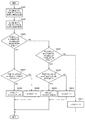
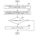
図2は図1の動画像符号化装置に対応した本発明の実施の形態に係る動画像復号装置200の構成を示すブロックである。実施の形態の動画像復号装置は、分離部201、第1符号化ビット列復号部202、第2符号化ビット列復号部203、参照インデックス導出部211、動きベクトル導出部204、インター予測情報推定部205、動き補償予測部206、逆量子化・逆直交変換部207、復号画像信号重畳部208、符号化情報格納メモリ209、および復号画像メモリ210を備える。
FIG. 2 is a block diagram showing a configuration of a moving
図2の動画像復号装置の復号処理は、図1の動画像符号化装置の内部に設けられている復号処理に対応するものであるから、図2の動き補償予測部206、逆量子化・逆直交変換部207、復号画像信号重畳部208、符号化情報格納メモリ209、および復号画像メモリ210の各構成は、図1の動画像符号化装置の動き補償予測部105、逆量子化・逆直交変換部112、復号画像信号重畳部113、符号化情報格納メモリ114、および復号画像メモリ115の各構成とそれぞれ対応する機能を有する。
The decoding process of the moving picture decoding apparatus in FIG. 2 corresponds to the decoding process provided in the moving picture encoding apparatus in FIG. 1, so the motion
分離部201に供給されるビットストリームは規定のシンタックスの規則に従って分離し、分離された符号化ビット列が第1符号化ビット列復号部202、第2符号化ビット列復号部203に供給される。
The bit stream supplied to the
第1符号化ビット列復号部202は、供給された符号化ビット列を復号して、シーケンス、ピクチャ、スライス、符号化ブロック単位の情報、及び、予測ブロック単位の符号化情報を得る。具体的には、符号化ブロック単位でインター予測(PRED_INTER)かイントラ予測(PRED_INTRA)かを判別する予測モードPredMode、分割モードPartMode、インター予測(PRED_INTER)の場合、予測ブロック単位でマージモードかどうかを判別するマージフラグ、マージフラグがマージモードの場合はマージインデックス、マージフラグがマージモードでない場合はインター予測モード、予測動きベクトルインデックス、差分動きベクトル等に関する符号化情報を規定のシンタックス規則に従って復号し、参照インデックス導出部211、符号化情報を動きベクトル導出部204およびインター予測情報推定部205に供給する。
The first encoded bit
なお、本実施の形態においては、インター予測モードが双予測において、スライス毎、または復号対象の予測ブロックのサイズに応じて、L1予測のインター予測情報を復号するかどうかを切り替える。切り替える対象となるインター予測情報は参照インデックス、予測動きベクトルインデックス、差分動きベクトルの一部、またはすべてである。そこで、第1符号化ビット列復号部202では、双予測においてL1のインター予測情報が符号化されるかどうかを示すフラグinterInfoCodingL1Flagが0または1に設定される。フラグinterInfoCodingL1Flagが1は双予測においてL1のインター予測情報が符号化されることを示し、フラグinterInfoCodingL1Flagが0は双予測においてL1のインター予測情報が符号化されないことを示す。設定された双予測においてL1のインター予測情報が符号化されるかどうかを示すフラグinterInfoCodingL1Flagの情報は参照インデックス導出部211、および動きベクトル導出部212に供給される。
In the present embodiment, when the inter prediction mode is bi-prediction, whether to decode L1 prediction inter prediction information is switched for each slice or according to the size of a prediction block to be decoded. The inter prediction information to be switched is a reference index, a prediction motion vector index, a part of or all of a difference motion vector. Therefore, in the first encoded bit
双予測でL1のインター予測情報が符号化されるかどうかを示すフラグinterInfoCodingL1Flagが1の場合、切り替える対象となるインター予測情報として双予測でのL1の差分動きベクトルが含まれる場合で、双予測でのL1の差分動きベクトルを復号しない場合、に双予測でのL1の差分動きベクトルが(0,0)に設定され、切り替える対象となるインター予測情報として双予測でのL1の予測動きベクトルインデックスが含まれる場合で、双予測でのL1の予測動きベクトルインデックスを復号しない場合、双予測でのL1の予測動きベクトルインデックスがL0の予測動きベクトルインデックスの値に設定され、符号化情報を参照インデックス導出部211および動きベクトル導出部204に供給する。なお、本実施の形態においては動きベクトル導出部204において切り替える対象となるインター予測情報として双予測でのL1の参照インデックスが含まれる場合で、双予測でのL1の参照インデックスを復号しない場合、双予測でのL1の参照インデックスを導出した値に設定するが、双予測でのL1の参照インデックスをデフォルト値に設定することもできる。その場合、第1符号化ビット列復号部202で、双予測でのL1の参照インデックスをデフォルト値に設定し、符号化情報を参照インデックス導出部211に供給する。
When the flag interInfoCodingL1Flag indicating whether or not the L1 inter prediction information is encoded by bi-prediction is 1, when the L1 differential motion vector in bi-prediction is included as the inter prediction information to be switched, the bi-prediction When the differential motion vector of L1 is not decoded, the differential motion vector of L1 in bi-prediction is set to (0, 0), and the predicted motion vector index of L1 in bi-prediction is set as inter prediction information to be switched. If the prediction motion vector index of L1 in bi-prediction is not decoded, the prediction motion vector index of L1 in bi-prediction is set to the value of the prediction motion vector index of L0, and the encoding information is derived as a reference index. To the
第2符号化ビット列復号部203は、供給された符号化ビット列を復号して直交変換・量子化された残差信号を算出し、直交変換・量子化された残差信号を逆量子化・逆直交変換部207に供給する。
The second encoded bit
参照インデックス導出部211は、供給された符号化情報から予測モードPredModeがインター予測(MODE_INTER)であり、マージフラグがマージモードでなく、インター予測モードが双予測(Pred_BI)であり、双予測においてL1のインター予測情報が符号化されるかどうかを示すフラグinterInfoCodingL1Flagが0の場合に、L1の参照インデックスを導出し、動き補償予測部206に供給する。符号化情報格納メモリに格納されている近接する予測ブロックのL1の参照インデックスを含む符号化情報を利用して、復号対象の予測ブロックのL1の参照インデックスを導出してもよいし、L0の参照インデックスに対応するL0の参照ピクチャがL1にも含まれている場合にL1でも同じ参照ピクチャを用いることとし、その参照ピクチャに対応するL1の参照インデックスを導出してもよい。
The reference
動きベクトル導出部204は、マージフラグがマージモードでない時に、符号化情報格納メモリ209に記憶されている既に復号された画像信号の符号化情報を用いて、複数の予測動きベクトルの候補を算出して後述する予測動きベクトルリストに登録し、予測動きベクトルリストに登録された複数の予測動きベクトルの候補の中から、第1符号化ビット列復号部202で復号され供給される予測動きベクトルインデックスに応じた予測動きベクトルを選択し、第1符号化ビット列復号部202で復号された差分ベクトルと選択された予測動きベクトルから動きベクトルを算出し、他の符号化情報とともに動き補償予測部206に供給するとともに、符号化情報格納メモリ209に格納する。ここで供給・格納する予測ブロックの符号化情報は、予測モードPredMode、分割モードPartMode、L0予測、及びL1予測を利用するかどうかを示すフラグpredFlagL0, predFlagL1、L0、L1の参照インデックスrefIdxL0, refIdxL1、L0、L1の動きベクトルmvL0, mvL1等である。ここで、予測モードPredModeがイントラ予測(MODE_INTRA)の場合、L0予測を利用するかどうかを示すフラグpredFlagL0、L1予測を利用するかどうかを示すフラグpredFlagL1は共に0である。一方、予測モードPredModeがインター予測(MODE_INTER)で、インター予測モードがL0予測(Pred_L0)の場合、L0予測を利用するかどうかを示すフラグpredFlagL0は1, L1予測を利用するかどうかを示すフラグpredFlagL1は0である。インター予測モードがL1予測(Pred_L1)の場合、L0予測を利用するかどうかを示すフラグpredFlagL0は0, L1予測を利用するかどうかを示すフラグpredFlagL1は1である。インター予測モードが双予測(Pred_BI)の場合、L0予測を利用するかどうかを示すフラグpredFlagL0、L1予測を利用するかどうかを示すフラグpredFlagL1は共に1である。動きベクトル導出部204の詳細な構成と動作は後述する。
When the merge flag is not in the merge mode, the motion
インター予測情報推定部205は、復号対象の予測ブロックのマージフラグがマージモードの時に、マージモードのインター予測情報を推定する。符号化情報格納メモリ114に記憶されている既に復号された予測ブロックの符号化情報を用いて、複数のマージの候補を算出してマージ候補リストに登録し、マージ候補リストに登録された複数のマージ候補の中から第1符号化ビット列復号部202で復号され供給されるマージインデックスに対応したマージ候補を選択し、選択されたマージ候補の予測モードPredMode、分割モードPartMode、L0予測、及びL1予測を利用するかどうかを示すフラグ、L0、L1の参照インデックス、L0、L1の動きベクトル等のインター予測情報を動き補償予測部206に供給するとともに、符号化情報格納メモリ209に格納する。
The inter prediction
動き補償予測部206は、動きベクトル導出部204で算出された動きベクトルを用いて参照ピクチャから動き補償予測により予測画像信号を生成し、予測画像信号を復号画像信号重畳部208に供給する。なお、双予測(Pred_BI)の場合は、L0予測、L1予測の2つの予測画像信号に適応的に重み係数を掛け算し、オフセット値を加算して重畳し、最終的な予測画像信号を生成する。
The motion compensated
逆量子化・逆直交変換部207は、第1符号化ビット列復号部202で復号された直交変換・量子化された残差信号に対して逆直交変換及び逆量子化を行い、逆直交変換・逆量子化された残差信号を得る。
The inverse quantization / inverse
復号画像信号重畳部208は、動き補償予測部206で動き補償予測された予測画像信号と、逆量子化・逆直交変換部207により逆直交変換・逆量子化された残差信号とを重畳することにより、復号画像信号を復号し、復号画像メモリ210に格納する。復号画像メモリ210に格納する際には、復号画像に対して符号化によるブロック歪等を減少させるフィルタリング処理を施して、復号画像メモリ210に格納されることもある。
The decoded image
本実施の形態の動画像符号化装置100および動画像復号装置200においては、インター予測モードが双予測において、スライス単位、または符号化または復号対象の予測ブロックのサイズに応じて、双予測でL1のインター予測情報を符号化または復号するかどうかを切り替える。
In the moving
スライス単位でL1のインター予測情報を符号化または復号するかどうかを切り替える場合、図10のスライスヘッダーのシンタックス構造の例に示すように、スライスヘッダーに双予測でL1のインター予測情報を符号化または復号するかどうかを示すフラグinterInfoCodingL1Flagを符号化または復号するためのシンタックス要素inter_info_coding_l1_flagを用意し、このシンタックス要素をスライスタイプがBスライスの場合に動画像符号化装置100の第1の符号化ビット列生成部109で符号化し、動画像復号装置200の第1符号化ビット列復号部202で復号することで、双予測においてL1のインター予測情報を符号化または復号するかどうかを判別する。また、スライス単位でL0のインター予測情報を符号化または復号するかどうかを切り替えてもよい。L0のインター予測情報を切り替える場合は、L0のインター予測情報を符号化または復号するかどうかを示すフラグinterInfoCodingL0Flagを符号化または復号するためのシンタックス要素inter_info_coding_l0_flagを用意して符号化または復号することで判別する。本実施の形態においては、差分動きベクトル、参照インデックス、予測動きベクトルインデックスの少なくとも1つを、符号化または復号するかどうかを切り替えることで符号量の削減を行う。例えば、双予測ではL1の差分動きベクトルだけを切り替え対象のインター予測情報とし、スライス単位で双予測のL1の差分予測動きベクトルだけを符号化または復号するかどうかを切り替える。符号化側で、双予測でのL1の動きベクトル検出処理を削減することで、演算量を削減する場合、または、L1の差分予測動きベクトルを省略することで符号化効率が向上すると判断した場合、双予測でL1のインター予測情報を符号化または復号するかどうかを示すフラグinterInfoCodingL1Flagの値を0としてシンタックス要素inter_info_coding_l1_flag を符号化または復号し、その値に応じて双予測のL1の差分動きベクトルの符号化および復号を省略することで、インター予測情報の符号量を削減する。双予測でL1の差分動きベクトルの符号化および復号を省略する際には符号化側、復号側共に、L1の差分動きベクトルの値を(0,0)とする。すなわち、双予測でL1の差分動きベクトルの符号化および復号を省略する際には符号化側、復号側共に、L1の予測動きベクトルをそのままL1の動きベクトルとする。
When switching whether to encode or decode L1 inter prediction information in units of slices, as shown in the example of the syntax structure of the slice header in FIG. 10, the L1 inter prediction information is encoded by bi-prediction in the slice header. Alternatively, a syntax element inter_info_coding_l1_flag for encoding or decoding a flag interInfoCodingL1Flag indicating whether or not to decode is prepared, and this syntax element is the first encoding of the
なお、参照インデックスだけを切り替え対象のインター予測情報としてもよいし、予測動きベクトルインデックスだけを切り替え対象のインター予測情報としてもよいし、すべてを切り替え対象のインター予測情報としてもよい。また、スライス単位で双予測のL1のインター予測情報だけを符号化または復号するかどうかを切り替えてもよいし、スライス単位で双予測のL0のインター予測情報だけを符号化または復号するかどうかを切り替えてもよい。ここでは、スライス単位で、双予測のL0およびL1のいずれか一方のインター予測情報において、差分動きベクトル、参照インデックス、および前記予測動きベクトルインデックスの少なくとも一つの符号化または復号を行わないモードに切り替えるようにする。 Note that only the reference index may be the inter prediction information to be switched, only the predicted motion vector index may be the inter prediction information to be switched, or all may be the inter prediction information to be switched. Also, whether to encode or decode only the bi-predicted L1 inter prediction information in units of slices may be switched, and whether to encode or decode only the bi-predicted L0 inter prediction information in units of slices. You may switch. Here, the mode is switched to a mode in which at least one of the differential motion vector, the reference index, and the predicted motion vector index is not encoded or decoded in the inter prediction information of one of L0 and L1 of bi-prediction in units of slices. Like that.
また、双予測でL1のインター予測情報を符号化または復号するかどうかを示すフラグinterInfoCodingL1Flagの代わりに、双予測でL1の参照インデックスを符号化または復号するかどうかを示すフラグrefIdxCodingL1Flag、双予測でL1の予測動きベクトルインデックスを符号化または復号するかどうかを示すフラグmvpIdxCodingL1Flag、または双予測でL1の差分予測動きベクトルを符号化または復号するかどうかを示すフラグmvdCodingL1Flagを用意してそれぞれ個別に切り替えることもできる。 また、双予測でL0の参照インデックスを符号化または復号するかどうかを示すフラグrefIdxCodingL0Flag、双予測でL0の予測動きベクトルインデックスを符号化または復号するかどうかを示すフラグmvpIdxCodingL0Flag、双予測でL0の差分予測動きベクトルを符号化または復号するかどうかを示すフラグmvdCodingL0Flagを用意してそれぞれ個別に切り替えることもできる。図11のスライスヘッダー のシンタックス構造の例に示すように、スライスヘッダーに双予測でL1の参照インデックスを符号化または復号するかどうかを示すフラグrefIdxCodingL1Flagを符号化または復号するためのシンタックス要素ref_idx_coding_l1_flag、双予測でL1の予測動きベクトルインデックスを符号化または復号するかどうかを示すフラグmvpIdxCodingL1Flagを符号化または復号するためのシンタックス要素mvp_idx_coding_l1_flag、双予測でL1の差分予測動きベクトルを符号化または復号するかどうかを示すフラグmvdCodingL1Flagを符号化または復号するためのシンタックス要素mvd_coding_l1_flag を用意し、これらのシンタックス要素をスライスタイプがBスライスの場合に動画像符号化装置100の第1の符号化ビット列生成部109で符号化し、動画像復号装置200の第1符号化ビット列復号部202で復号することで、双予測においてL1のそれぞれのインター予測情報を符号化または復号するかどうかを判別することもできる。また、L0のそれぞれのインター予測情報を切り替える場合は、双予測でL0の参照インデックスを符号化または復号するかどうかを示すフラグrefIdxCodingL0Flagを符号化または復号するためのシンタックス要素ref_idx_coding_l0_flag、双予測でL0の予測動きベクトルインデックスを符号化または復号するかどうかを示すフラグmvpIdxCodingL0Flagを符号化または復号するためのシンタックス要素mvp_idx_coding_l0_flag、双予測でL0の差分予測動きベクトルを符号化または復号するかどうかを示すフラグmvdCodingL0Flagを符号化または復号するためのシンタックス要素mvd_coding_l0_flagを用意して符号化または復号することで判別する。本実施の形態においては、これらのインター予測情報の少なくとも1つを、符号化または復号するかどうかを切り替えることで符号量の削減を行う。例えば、双予測ではL1の差分動きベクトルだけを切り替え対象のインター予測情報とし、スライス単位で双予測のL1の差分予測動きベクトルだけを符号化または復号するかどうかを切り替える。符号化側で、双予測でのL1の動きベクトル検出処理を削減することで、演算量を削減する場合、または、L1の差分予測動きベクトルを省略することで符号化効率が向上すると判断した場合、双予測でL1の差分予測動きベクトルを符号化または復号するかどうかを示すフラグmvdCodingL1Flagの値を0としてシンタックス要素mvp_idx_coding_l1_flag を符号化または復号し、その値に応じて双予測のL1の差分動きベクトルの符号化および復号を省略することで、インター予測情報の符号量を削減する。双予測でL1の差分動きベクトルの符号化および復号を省略する際には符号化側、復号側共に、L1の差分動きベクトルを(0,0)とする。すなわち、双予測でL1の差分動きベクトルの符号化および復号を省略する際には符号化側、復号側共に、L1の予測動きベクトルをそのままL1の動きベクトルとする。
Also, instead of the flag interInfoCodingL1Flag indicating whether or not L1 inter prediction information is encoded or decoded in bi-prediction, the flag refIdxCodingL1Flag indicating whether or not the L1 reference index is encoded or decoded in bi-prediction, and L1 in bi-prediction It is also possible to prepare a flag mvpIdxCodingL1Flag indicating whether or not to encode or predict the predicted motion vector index, or a flag mvdCodingL1Flag indicating whether or not to encode or decode the L1 differential prediction motion vector in bi-prediction, it can. Also, a flag refIdxCodingL0Flag indicating whether or not the L0 reference index is encoded or decoded in bi-prediction, a flag mvpIdxCodingL0Flag indicating whether or not the L0 motion vector index is encoded or decoded in bi-prediction, and the difference of L0 in bi-prediction It is also possible to prepare a flag mvdCodingL0Flag indicating whether or not to encode or decode a predicted motion vector and switch them individually. As shown in the example of the syntax structure of the slice header in FIG. 11, a syntax element ref_idx_coding_l1_flag for encoding or decoding a flag refIdxCodingL1Flag indicating whether or not the L1 reference index is encoded or decoded by bi-prediction in the slice header , A syntax element mvp_idx_coding_l1_flag for encoding or decoding a flag mvpIdxCodingL1Flag indicating whether to encode or decode the L1 motion vector predictor index in bi-prediction, and L1 differential prediction motion vector in bi-prediction A syntax element mvd_coding_l1_flag for encoding or decoding a flag mvdCodingL1Flag indicating whether or not the first encoding bit sequence of the
なお、スライス単位で双予測のL0の差分予測動きベクトルだけを符号化または復号するかどうかを切り替えてもよい。また、スライス単位で双予測のL1の参照インデックスだけを符号化または復号するかどうかを切り替えてもよいし、スライス単位で双予測のL0の参照インデックスだけを符号化または復号するかどうかを切り替えてもよい。また、スライス単位で双予測のL1の参照インデックスだけを符号化または復号するかどうかを切り替えてもよいし、スライス単位で双予測のL0の参照インデックスだけを符号化または復号するかどうかを切り替えてもよい。また、スライス単位で双予測のL1の予測動きベクトルインデックスだけを符号化または復号するかどうかを切り替えてもよいし、スライス単位で双予測のL0の予測動きベクトルインデックスだけを符号化または復号するかどうかを切り替えてもよい。スライス単位で、双予測のL0およびL1の差分予測動きベクトルをそれぞれ符号化または復号するかどうかを切り替えてもよいし、双予測のL0およびL1の参照インデックスをそれぞれ符号化または復号するかどうかを切り替えてもよいし、双予測のL0およびL1の予測動きベクトルインデックスをそれぞれ符号化または復号するかどうかを切り替えてもよい。また、スライス単位で双予測のL1の差分動きベクトル、参照インデックス、予測動きベクトルインデックスをそれぞれ符号化または復号するかどうかを切り替えてもよいし、スライス単位で双予測のL0の差分動きベクトル、参照インデックス、予測動きベクトルインデックスをそれぞれ符号化または復号するかどうかを切り替えてもよい。ここでは、スライス単位で、双予測のL0およびL1のいずれか一方のインター予測情報において、差分動きベクトル、参照インデックス、および前記予測動きベクトルインデックスの少なくとも一つの符号化または復号を行わないモードに切り替えるようにする。 Note that whether or not to encode or decode only the bi-predicted L0 differential prediction motion vector may be switched in units of slices. Further, whether to encode or decode only the bi-predictive L1 reference index in units of slices may be switched or whether to encode or decode only the bi-predictive L0 reference index in units of slices. Also good. Further, whether to encode or decode only the bi-predictive L1 reference index in units of slices may be switched or whether to encode or decode only the bi-predictive L0 reference index in units of slices. Also good. Further, whether to encode or decode only the prediction motion vector index of bi-predicted L1 in units of slices may be switched, or whether to encode or decode only the prediction motion vector index of bi-prediction L0 in units of slices. It may be switched. Whether to encode or decode bi-predictive L0 and L1 differential prediction motion vectors, respectively, or to encode or decode bi-predictive L0 and L1 reference indexes, respectively, in units of slices. Switching may be performed, and whether to predict or decode bi-predicted L0 and L1 motion vector predictor indexes may be switched. Also, whether to encode or decode the bi-predicted L1 differential motion vector, reference index, and predicted motion vector index may be switched in units of slices, or bi-predicted L0 differential motion vector and reference in units of slices. Whether to encode or decode the index and the motion vector predictor index may be switched. Here, the mode is switched to a mode in which at least one of the differential motion vector, the reference index, and the predicted motion vector index is not encoded or decoded in the inter prediction information of one of L0 and L1 of bi-prediction in units of slices. Like that.
次に、符号化または復号対象の予測ブロックのサイズに応じてL1のインター予測情報を符号化または復号するかどうかを切り替える場合について、図12を用いて説明する。これらの処理は、本実施の形態の動画像符号化装置100および動画像復号装置200の各ブロックにおいて、必要に応じて行われる。
Next, a case of switching whether to encode or decode L1 inter prediction information according to the size of a prediction block to be encoded or decoded will be described with reference to FIG. These processes are performed as necessary in each block of the
図12は符号化または復号対象の予測ブロックのサイズに応じて切り替える場合の双予測でL1のインター予測情報を符号化または復号するかどうかを示すフラグinterInfoCodingL1Flagの設定処理手順を示すフローチャートである。 FIG. 12 is a flowchart illustrating a setting process procedure of a flag interInfoCodingL1Flag indicating whether to encode or decode L1 inter prediction information in bi-prediction when switching according to the size of a prediction block to be encoded or decoded.
まず、符号化または復号対象の予測ブロックのサイズを得る(ステップS401)。符号化または復号対象の予測ブロックのサイズが規定したサイズsizePUInterPredInfoCodingL1以下の場合(ステップS402のYES)、フラグinterInfoCodingL1Flagを0に設定する(ステップS403)。一方、符号化または復号対象の予測ブロックのサイズが規定したサイズsizePUInterPredInfoCodingL1より大きい場合(ステップS402のNO)、interInfoCodingL1Flagを1に設定する(ステップS404)。本実施の形態においては、規定するサイズsizePUInterPredInfoCodingL1を8x8とする。なお、規定するサイズsizePUInterPredInfoCodingL1は固定された値であってもよいし、シーケンス、ピクチャまたはスライス単位でシンタックス要素を用意して任意の値に設定してもよい。また、8x4と4x8等、幅と高さを乗じた値が等しいサイズの場合は同じサイズとみなす。即ち、規定するサイズsizePUInterPredInfoCodingL1が8x4と設定された場合、4x8も設定されたものとみなす。また、ステップS402で、符号化または復号対象の予測ブロックのサイズが規定したサイズsizePUInterPredInfoCodingL1未満の場合、interInfoCodingL1Flagを0に設定し、そうでない場合、interInfoCodingL1Flagを1に設定するとしてもよい。 First, the size of the prediction block to be encoded or decoded is obtained (step S401). When the size of the prediction block to be encoded or decoded is equal to or smaller than the size sizePUInterPredInfoCodingL1 (YES in step S402), the flag interInfoCodingL1Flag is set to 0 (step S403). On the other hand, when the size of the prediction block to be encoded or decoded is larger than the specified size sizePUInterPredInfoCodingL1 (NO in step S402), interInfoCodingL1Flag is set to 1 (step S404). In the present embodiment, the prescribed size sizePUInterPredInfoCodingL1 is 8 × 8. The prescribed size sizePUInterPredInfoCodingL1 may be a fixed value, or may be set to an arbitrary value by preparing a syntax element for each sequence, picture, or slice. In addition, if the size is the same size, such as 8x4 and 4x8, multiplied by the width and height, it is considered the same size. That is, when the specified size sizePUInterPredInfoCodingL1 is set to 8x4, it is considered that 4x8 is also set. In step S402, if the size of the prediction block to be encoded or decoded is smaller than the specified size sizePUInterPredInfoCodingL1, interInfoCodingL1Flag may be set to 0. Otherwise, interInfoCodingL1Flag may be set to 1.
図1の動画像符号化装置の第1の符号化ビット列生成部109で実施される予測ブロック単位のインター予測情報のエントロピー符号化処理手順について、図13のフローチャートを用いて説明する。まず予測ブロック単位でマージモードかどうかを判別するマージフラグmergeFlagを符号化する(ステップS501)。マージフラグが1の場合(ステップS502のYES)、インター予測情報推定部104で選択されたマージ候補を特定するマージインデックスmergeIdxを符号化し(ステップS503)、本符号化処理手順を終了する。
An entropy encoding process procedure for inter prediction information in units of prediction blocks, which is performed by the first encoded bit
一方、マージフラグが0の場合(ステップS502のNO)、ステップS504、およびS505の条件判断を実施する。インター予測モードがL0予測の場合(ステップS504のYES)、L0の参照インデックスrefIdxL0を符号化し(ステップS506)、L0の予測動きベクトルインデックスmvpIdxL0を符号化し(ステップS507)、L0の差分動きベクトルを符号化し(ステップS508)、本符号化処理手順を終了する。 On the other hand, when the merge flag is 0 (NO in step S502), the condition determination in steps S504 and S505 is performed. When the inter prediction mode is L0 prediction (YES in step S504), the L0 reference index refIdxL0 is encoded (step S506), the L0 prediction motion vector index mvpIdxL0 is encoded (step S507), and the L0 differential motion vector is encoded. (Step S508), and the present encoding process procedure ends.
一方、インター予測モードがL1予測の場合(ステップS504のNO、ステップS505のYES)、L1の参照インデックスrefIdxL1を符号化し(ステップS509)、L1の予測動きベクトルインデックスmvpIdxL1を符号化し(ステップS510)、L1の差分動きベクトルを符号化し(ステップS511)、本符号化処理手順を終了する。 On the other hand, when the inter prediction mode is L1 prediction (NO in step S504, YES in step S505), the L1 reference index refIdxL1 is encoded (step S509), and the L1 prediction motion vector index mvpIdxL1 is encoded (step S510). The differential motion vector of L1 is encoded (step S511), and this encoding processing procedure is terminated.
一方、インター予測モードが双予測の場合(ステップS504のNO、ステップS505のNO)、L0の参照インデックスrefIdxL0を符号化し(ステップS512)、L0の予測動きベクトルインデックスmvpIdxL0を符号化し(ステップS513)、L0の差分動きベクトルを符号化する(ステップS514)。 On the other hand, if the inter prediction mode is bi-prediction (NO in step S504, NO in step S505), the L0 reference index refIdxL0 is encoded (step S512), and the L0 prediction motion vector index mvpIdxL0 is encoded (step S513). The differential motion vector of L0 is encoded (step S514).
続いて、フラグinterPredInfoCodingL1Flagが1、即ち、L1のインター予測情報を符号化する場合(ステップS516のYES)、L1の参照インデックスrefIdxL1を符号化し(ステップS517)、L1の予測動きベクトルインデックスmvpIdxL1を符号化し(ステップS518)、L1の差分動きベクトルを符号化し(ステップS519)、本符号化処理手順を終了する。 Subsequently, when the flag interPredInfoCodingL1Flag is 1, that is, when the L1 inter prediction information is encoded (YES in step S516), the L1 reference index refIdxL1 is encoded (step S517), and the L1 motion vector predictor index mvpIdxL1 is encoded. (Step S518), the differential motion vector of L1 is encoded (Step S519), and this encoding processing procedure is terminated.
一方、フラグinterPredInfoCodingL1Flagが0、即ち、L1のインター予測情報を符号化しない場合(ステップS516のNO)、本符号化処理手順を終了する。 On the other hand, when the flag interPredInfoCodingL1Flag is 0, that is, when the inter prediction information of L1 is not encoded (NO in step S516), the encoding processing procedure is terminated.
次に、図2の動画像復号装置の第1符号化ビット列復号部202で実施される予測ブロック単位のインター予測情報のエントロピー復号処理手順について、図14のフローチャートを用いて説明する。まず予測ブロック単位でマージモードかどうかを判別するマージフラグmergeFlagを復号する(ステップS601)。マージフラグが1の場合(ステップS602のYES)、インター予測情報推定部104で選択されたマージ候補を特定するマージインデックスmergeIdxを復号し(ステップS603)、本復号処理手順を終了する。
Next, an entropy decoding process procedure for inter prediction information in units of prediction blocks, which is performed by the first encoded bit
一方、マージフラグが0の場合(ステップS602のNO)、ステップS604、およびS605の条件判断を実施する。インター予測モードがL0予測の場合(ステップS604のYES)、L0の参照インデックスrefIdxL0を復号し(ステップS606)、L0の予測動きベクトルインデックスmvpIdxL0を復号し(ステップS607)、L0の差分動きベクトルを復号し(ステップS608)、本復号処理手順を終了する。 On the other hand, if the merge flag is 0 (NO in step S602), the condition determination in steps S604 and S605 is performed. When the inter prediction mode is L0 prediction (YES in step S604), the reference index refIdxL0 of L0 is decoded (step S606), the prediction motion vector index mvpIdxL0 of L0 is decoded (step S607), and the differential motion vector of L0 is decoded. (Step S608), and this decoding processing procedure is terminated.
一方、インター予測モードがL1予測の場合(ステップS604のNO、ステップS605のYES)、L1の参照インデックスrefIdxL1を復号し(ステップS609)、L1の予測動きベクトルインデックスmvpIdxL1を復号し(ステップS610)、L1の差分動きベクトルを復号し(ステップS611)、本復号処理手順を終了する。 On the other hand, when the inter prediction mode is L1 prediction (NO in step S604, YES in step S605), the L1 reference index refIdxL1 is decoded (step S609), and the L1 prediction motion vector index mvpIdxL1 is decoded (step S610). The difference motion vector of L1 is decoded (step S611), and this decoding processing procedure is ended.
一方、インター予測モードが双予測の場合(ステップS604のNO、ステップS605のNO)、L0の参照インデックスrefIdxL0を復号し(ステップS612)、L0の予測動きベクトルインデックスmvpIdxL0を復号し(ステップS613)、L0の差分動きベクトルを復号する(ステップS614)。 On the other hand, when the inter prediction mode is bi-prediction (NO in step S604, NO in step S605), the L0 reference index refIdxL0 is decoded (step S612), and the L0 prediction motion vector index mvpIdxL0 is decoded (step S613). The differential motion vector of L0 is decoded (step S614).
続いて、フラグinterPredInfoCodingL1Flagを設定する(ステップS615)。復号対象の予測ブロックのサイズに応じて切り替える場合は、図17を用いて説明した方法により、フラグinterPredInfoCodingL1Flagを設定する。なお、スライス単位でL1のインター予測情報を復号するかどうかを切り替える場合はフラグinterPredInfoCodingL1Flagはスライスヘッダ復号時に設定される。 Subsequently, a flag interPredInfoCodingL1Flag is set (step S615). When switching according to the size of the prediction block to be decoded, the flag interPredInfoCodingL1Flag is set by the method described with reference to FIG. When switching whether to decode L1 inter prediction information in units of slices, the flag interPredInfoCodingL1Flag is set at the time of slice header decoding.
続いて、フラグinterPredInfoCodingL1Flagが1、即ち、L1のインター予測情報を復号する場合(ステップS616のYES)、L1の参照インデックスrefIdxL1を復号し(ステップS617)、L1の予測動きベクトルインデックスmvpIdxL1を復号し(ステップS618)、L1の差分動きベクトルを復号し(ステップS619)、本復号処理手順を終了する。 Subsequently, when the flag interPredInfoCodingL1Flag is 1, that is, when the L1 inter prediction information is decoded (YES in step S616), the L1 reference index refIdxL1 is decoded (step S617), and the L1 motion vector predictor index mvpIdxL1 is decoded ( Step S618), the differential motion vector of L1 is decoded (Step S619), and this decoding processing procedure is terminated.
一方、フラグinterPredInfoCodingL1Flagが0、即ち、L1のインター予測情報を復号しない場合(ステップS616のNO)、参照インデックス導出部211でL1の参照インデックスrefIdxL1を導出する(ステップS620)。続いて、L1の予測動きベクトルインデックスmvpIdxL1をL0の予測動きベクトルインデックスmvpIdxL0の値に設定する(ステップS621)。続いて、L1の差分動きベクトルを(0,0)に設定し(ステップS622)、本復号処理手順を終了する。
On the other hand, when the flag interPredInfoCodingL1Flag is 0, that is, when the inter prediction information of L1 is not decoded (NO in step S616), the reference
次に、図1の参照インデックス導出部116、及び図2の参照インデックス導出部211で実施される双予測でのL1の参照インデックスを導出する方法について詳細に説明する。
Next, a method for deriving the L1 reference index in bi-prediction performed by the reference
本実施の形態においては、周辺の予測ブロックで利用された参照インデックスを利用して符号化または復号対象の予測ブロックの双予測でのL1の参照インデックスrefIdxLXを導出する。これは、符号化または復号対象の予測ブロックの参照インデックスは周辺の予測ブロックの参照インデックスと高い相関を持つと考えられるからである。特に、符号化または復号対象の予測ブロックの左の辺に近接する予測ブロックA1、及び上の辺に近接する予測ブロックB1の参照インデックスだけを利用する。なぜなら、図5に示す近接する予測ブロックA0,A1,B0,B1,B2の中でも符号化または復号対象の予測ブロックの辺に接している予測ブロックA1,B1は、符号化または復号対象の予測ブロックの頂点に接している予測ブロックA0,B0,B2よりも相関が高いと考えられるからである。あえて予測ブロックA0,B0,B2を利用せずに、利用する予測ブロックを予測ブロックA1,B1に限定することで、参照インデックスの導出による符号化効率の改善効果を得るとともに、参照インデックス導出処理に関する演算量及びメモリアクセス量を削減する。 In the present embodiment, the reference index refIdxLX of L1 in the bi-prediction of the prediction block to be encoded or decoded is derived using the reference index used in the surrounding prediction block. This is because it is considered that the reference index of the prediction block to be encoded or decoded has a high correlation with the reference indexes of neighboring prediction blocks. In particular, only the reference indexes of the prediction block A1 close to the left side of the prediction block to be encoded or decoded and the prediction block B1 close to the upper side are used. This is because, among the adjacent prediction blocks A0, A1, B0, B1, and B2 shown in FIG. 5, the prediction blocks A1 and B1 that are in contact with the sides of the prediction block to be encoded or decoded are the prediction blocks to be encoded or decoded. This is because the correlation is considered to be higher than that of the prediction blocks A0, B0, and B2 that are in contact with the vertices. The prediction block to be used is limited to the prediction blocks A1 and B1 without using the prediction blocks A0, B0, and B2, thereby obtaining the improvement effect of the encoding efficiency by the derivation of the reference index, and the reference index derivation process Reduce the amount of computation and memory access.
(実施例1)
以下、本実施の形態をいくつかの実施例に分けて説明する。まず、本実施の形態の実施例1について説明する。本実施の形態の実施例1では、予測ブロックA1、予測ブロックB1が共にLX予測(参照インデックスの導出対象のリストをLXとし、LXを用いた予測をLX予測とする。つまり、L0の参照インデックスを導出する際にはLXはL0に設定され、L1の参照インデックスを導出する際にはLXはL1に設定される。以下、断りのない限り、この意味で用いる。)を行う場合は予測ブロックA1、予測ブロックB1のLXの参照インデックスの値の小さい方を符号化または復号対象の予測ブロックの双予測でのLXの参照インデックスの値として採用する。ここで、双予測はL0予測とL1予測を共に行うものとする。ただし、予測ブロックA1、予測ブロックB1のいずれか一方しかLX予測を行わない場合はLX予測を行う方の予測ブロックのLXの参照インデックスの値を符号化または復号対象の予測ブロックの双予測でのLXの参照インデックスの値として採用し、予測ブロックA1、予測ブロックB1が共にLX予測を行わない場合は符号化または復号対象の予測ブロックの双予測でのLXの参照インデックスの値をデフォルト値の0とする。
Example 1
Hereinafter, this embodiment will be described by dividing it into several examples. First, Example 1 of the present embodiment will be described. In Example 1 of the present embodiment, both the prediction block A1 and the prediction block B1 are LX predictions (a list from which a reference index is derived is LX, and prediction using LX is LX prediction. That is, a reference index of L0) LX is set to L0 when L is derived, and LX is set to L1 when the reference index of L1 is derived.Hereafter, this is used in this sense unless otherwise noted). The smaller LX reference index value of A1 and prediction block B1 is adopted as the LX reference index value in bi-prediction of the prediction block to be encoded or decoded. Here, bi-prediction performs both L0 prediction and L1 prediction. However, when only one of the prediction block A1 and the prediction block B1 performs LX prediction, the value of the LX reference index of the prediction block that performs LX prediction is encoded or decoded by bi-prediction of the prediction block to be decoded. When the prediction block A1 and the prediction block B1 do not perform LX prediction, the LX reference index value in bi-prediction of the prediction block to be encoded or decoded is the
予測ブロックA1、予測ブロックB1が共にLX予測を行わない場合に符号化または復号対象の予測ブロックの双予測でのLXの参照インデックスのデフォルト値を0とする理由は、インター予測において参照インデックスの値が0に対応する参照ピクチャが最も選択される確率が高いからである。ただし、これに限定されず、参照インデックスのデフォルト値を0以外の値(1、2など)としても良いし、シーケンスレベル、ピクチャレベル、またはスライスレベルで符号化ストリーム内に参照インデックスのデフォルト値を示すシンタックス要素を設置し伝送できるようにして、符号化側で選択できるようにしても良い。 The reason why the default value of the LX reference index in bi-prediction of the prediction block to be encoded or decoded when both the prediction block A1 and the prediction block B1 do not perform LX prediction is that the value of the reference index in inter prediction This is because there is a high probability that the reference picture corresponding to 0 is most selected. However, the present invention is not limited to this, and the default value of the reference index may be a value other than 0 (1, 2, etc.), and the default value of the reference index may be set in the encoded stream at the sequence level, picture level, or slice level. The syntax element shown may be installed and transmitted so that it can be selected on the encoding side.
図15は本実施の形態の実施例1の方法による符号化または復号対象の予測ブロックの双予測でのLXの参照インデックスrefIdxLXの導出処理手順を説明するフローチャートである。まず、符号化情報格納メモリ114または209から左に近接する予測ブロックA1の符号化情報、及び予測ブロックB1の符号化情報を取得する(ステップS6101、ステップS6102)。
FIG. 15 is a flowchart for explaining a derivation process procedure of an LX reference index refIdxLX in bi-prediction of a prediction block to be encoded or decoded by the method of Example 1 of the present embodiment. First, the encoding information of the prediction block A1 adjacent to the left and the encoding information of the prediction block B1 are acquired from the encoding
予測ブロックAのLX予測を行うかどうかを示すフラグpredFlagLX[xA][yA]と予測ブロックB1のLX予測を行うかどうかを示すフラグpredFlagLX[xB][yB]が共に0でない場合(ステップS6103のYES)、LXの参照インデックスrefIdxLXを予測ブロックA1のLXの参照インデックスrefIdxLX[xA][yA]と予測ブロックB1のLXの参照インデックスrefIdxLX[xB][yB]の値の小さい方と同じ値に設定し(ステップS6104)、本参照インデックス導出処理を終了する。ここで、xA、yAはピクチャ内での予測ブロックA1の左上の画素の位置を示すインデックスである。ここで、xB、yBはピクチャ内での予測ブロックB1の左上の画素の位置を示すインデックスである。 When both the flag predFlagLX [xA] [yA] indicating whether to perform LX prediction of the prediction block A and the flag predFlagLX [xB] [yB] indicating whether to perform LX prediction of the prediction block B1 are not 0 (in step S6103) YES), the LX reference index refIdxLX is set to the same value as the smaller of the LX reference index refIdxLX [xA] [yA] of the prediction block A1 and the LX reference index refIdxLX [xB] [yB] of the prediction block B1 In step S6104, the reference index deriving process is terminated. Here, xA and yA are indexes indicating the position of the upper left pixel of the prediction block A1 in the picture. Here, xB and yB are indexes indicating the position of the upper left pixel of the prediction block B1 in the picture.
なお、本実施の形態においては、予測ブロックN(N=A,B)において、予測ブロックNが符号化または復号対象のスライス外で利用できない場合や予測ブロックNが符号化または復号順序で符号化または復号対象の予測ブロックよりも後のために符号化または復号されておらず利用できない場合や予測ブロックNの予測モードPredModeがイントラ予測(MODE_INTRA)の場合、L0予測を利用するかどうかを示すフラグpredFlagL0[xN][yN]、予測ブロックNのL1予測を利用するかどうかを示すフラグpredFlagL1[xN][yN]は共に0である。ここで、xN、yNはピクチャ内での予測ブロックNの左上の画素の位置を示すインデックスである。予測ブロックNの予測モードPredModeがインター予測(MODE_INTER)で、インター予測モードがL0予測(Pred_L0)の場合、予測ブロックNのL0予測を利用するかどうかを示すフラグpredFlagL0[xN][yN]は1, L1予測を利用するかどうかを示すフラグpredFlagL1[xN][yN]は0である。予測ブロックNのインター予測モードがL1予測(Pred_L1)の場合、予測ブロックNのL0予測を利用するかどうかを示すフラグpredFlagL0[xN][yN]は0, L1予測を利用するかどうかを示すフラグpredFlagL1[xN][yN]は1である。予測ブロックNのインター予測モードが双予測(Pred_BI)の場合、予測ブロックNのL0予測を利用するかどうかを示すフラグpredFlagL0[xN][yN]、L1予測を利用するかどうかを示すフラグpredFlagL1[xN][yN]は共に1である。 In the present embodiment, in the prediction block N (N = A, B), when the prediction block N cannot be used outside the slice to be encoded or decoded, the prediction block N is encoded or encoded in the decoding order. Alternatively, a flag indicating whether or not to use L0 prediction when the encoding block is not encoded or decoded after the decoding target prediction block and cannot be used, or when the prediction mode PredMode of the prediction block N is intra prediction (MODE_INTRA). Both predFlagL0 [xN] [yN] and the flag predFlagL1 [xN] [yN] indicating whether to use the L1 prediction of the prediction block N are 0. Here, xN and yN are indexes indicating the position of the upper left pixel of the prediction block N in the picture. When the prediction mode PredMode of the prediction block N is inter prediction (MODE_INTER) and the inter prediction mode is L0 prediction (Pred_L0), the flag predFlagL0 [xN] [yN] indicating whether to use the L0 prediction of the prediction block N is 1 , Flag predFlagL1 [xN] [yN] indicating whether to use L1 prediction is zero. When the inter prediction mode of the prediction block N is L1 prediction (Pred_L1), a flag predFlagL0 [xN] [yN] indicating whether or not to use the L0 prediction of the prediction block N is 0 and a flag indicating whether or not to use the L1 prediction predFlagL1 [xN] [yN] is 1. When the inter prediction mode of the prediction block N is bi-prediction (Pred_BI), a flag predFlagL0 [xN] [yN] indicating whether to use the L0 prediction of the prediction block N, and a flag predFlagL1 [indicating whether to use the L1 prediction xN] [yN] are both 1.
予測ブロックA1のLX予測を行うかどうかを示すフラグpredFlagLX[xA][yA]が0でなく、予測ブロックB1のLX予測を行うかどうかを示すフラグpredFlagLX[xB][yB]が0である場合(ステップS6103のNOで、ステップS6105のYES)、LXの参照インデックスrefIdxLXを予測ブロックA1のLXの参照インデックスrefIdxLX[xA][yA]と同じ値に設定し(ステップS6106)、本参照インデックス導出処理を終了する。ここで、xA、yAはピクチャ内での予測ブロックA1の左上の画素の位置を示すインデックスであり、xB、yBはピクチャ内での予測ブロックB1の左上の画素の位置を示すインデックスである。 When the flag predFlagLX [xA] [yA] indicating whether to perform LX prediction of the prediction block A1 is not 0 and the flag predFlagLX [xB] [yB] indicating whether to perform LX prediction of the prediction block B1 is 0 (NO in step S6103, YES in step S6105), the LX reference index refIdxLX is set to the same value as the LX reference index refIdxLX [xA] [yA] of the prediction block A1 (step S6106), and this reference index derivation process Exit. Here, xA and yA are indices indicating the position of the upper left pixel of the prediction block A1 in the picture, and xB and yB are indices indicating the position of the upper left pixel of the prediction block B1 in the picture.
予測ブロックA1のLX予測を行うかどうかを示すフラグpredFlagLX[xA][yA]が0であり、予測ブロックB1のLX予測を行うかどうかを示すフラグpredFlagLX[xB][yB]が0でない場合(ステップS6103のNOで、ステップS6105のNOで、ステップS2107のYES)、LXの参照インデックスrefIdxLXを予測ブロックB1のLXの参照インデックス refIdxLX[xB][yB]と同じ値に設定し(ステップS6108)、本参照インデックス導出処理を終了する。 When the flag predFlagLX [xA] [yA] indicating whether to perform LX prediction of the prediction block A1 is 0 and the flag predFlagLX [xB] [yB] indicating whether to perform LX prediction of the prediction block B1 is not 0 ( NO in step S6103, NO in step S6105, YES in step S2107), the LX reference index refIdxLX is set to the same value as the LX reference index refIdxLX [xB] [yB] in the prediction block B1 (step S6108), The reference index derivation process is terminated.
予測ブロックA1のLX予測を行うかどうかを示すフラグpredFlagLX[xA][yA]と予測ブロックB1のLX予測を行うかどうかを示すフラグpredFlagLX[xB][yB]が共に0である場合(ステップS6103のNOで、ステップS6105のNOで、ステップS6107のNO)、のLXの参照インデックスrefIdxLXをデフォルト値の0に設定し(ステップS6109)、本参照インデックス導出処理を終了する。 When the flag predFlagLX [xA] [yA] indicating whether to perform LX prediction of the prediction block A1 and the flag predFlagLX [xB] [yB] indicating whether to perform LX prediction of the prediction block B1 are both 0 (step S6103) In step S6105, step S6105 is NO, step S6107 is NO), the LX reference index refIdxLX is set to a default value of 0 (step S6109), and the reference index derivation process ends.
(実施例2)
次に、本実施の形態の実施例2について説明する。本実施の形態の実施例2においても、実施例1と同様に左の辺に近接する予測ブロックA1、及び上の辺に近接する予測ブロックB1の参照インデックスを利用して符号化または復号対象の予測ブロックの双予測でのLXの参照インデックスを導出する。実施例1に対して、図15のステップS6103、ステップS6104の処理を省略し、予測ブロックA1、予測ブロックB1の順序で、LX予測を行うかどうかを判定して、最初に見つかったLX予測を行う予測ブロックの参照インデックスを採用することでさらに処理量を削減する点が異なる。予測ブロックA1がLX予測を行う場合は予測ブロックA1のLXの参照インデックスを符号化または復号対象の予測ブロックの双予測でのLXの参照インデックスの値として採用し、予測ブロックA1がLX予測を行わず、予測ブロックB1がLX予測を行う場合は予測ブロックB1のLXの参照インデックスを符号化または復号対象の予測ブロックの双予測でのLXの参照インデックスの値として採用する。予測ブロックA1、予測ブロックB1が共にLX予測を行わない場合はLXの参照インデックスの値をデフォルト値の0とする。
(Example 2)
Next, Example 2 of the present embodiment will be described. Also in Example 2 of the present embodiment, similar to Example 1, the reference index of the prediction block A1 that is close to the left side and the prediction block B1 that is close to the upper side is used for encoding or decoding. A reference index of LX in bi-prediction of the prediction block is derived. Compared to the first embodiment, the processing in step S6103 and step S6104 in FIG. 15 is omitted, and it is determined whether or not LX prediction is performed in the order of the prediction block A1 and the prediction block B1, and the LX prediction first found is determined. The difference is that the processing amount is further reduced by adopting the reference index of the prediction block to be performed. When the prediction block A1 performs LX prediction, the LX reference index of the prediction block A1 is adopted as the value of the LX reference index in the bi-prediction of the prediction block to be encoded or decoded, and the prediction block A1 performs LX prediction Instead, when the prediction block B1 performs LX prediction, the LX reference index of the prediction block B1 is adopted as the value of the LX reference index in the bi-prediction of the prediction block to be encoded or decoded. When neither the prediction block A1 nor the prediction block B1 performs LX prediction, the value of the LX reference index is set to 0, which is the default value.
図16は本実施の形態の実施例2の方法による符号化または復号対象の予測ブロックの双予測でのLXの参照インデックスrefIdxLXの導出処理手順を説明するフローチャートである。まず、符号化情報格納メモリ114または209から左に近接する予測ブロックA1の符号化情報、及び予測ブロックB1の符号化情報を取得する(ステップS6201、ステップS6202)。なお、L0の参照インデックスを導出する際にはLXはL0に設定され、L1の参照インデックスを導出する際にはLXはL1に設定される。
FIG. 16 is a flowchart for explaining a derivation process procedure of the LX reference index refIdxLX in the bi-prediction of the prediction block to be encoded or decoded by the method of Example 2 of the present embodiment. First, the encoding information of the prediction block A1 adjacent to the left and the encoding information of the prediction block B1 are acquired from the encoding
予測ブロックA1のLX予測を行うかどうかを示すフラグpredFlagLX[xA][yA]が0でない場合(ステップS6203のYES)、LXの参照インデックスrefIdxLXを予測ブロックA1のLXの参照インデックスrefIdxLX[xA][yA]と同じ値に設定し(ステップS6204)、本参照インデックス導出処理を終了する。 If the flag predFlagLX [xA] [yA] indicating whether to perform LX prediction of the prediction block A1 is not 0 (YES in step S6203), the LX reference index refIdxLX is used as the LX reference index refIdxLX [xA] [xA] [ yA] is set to the same value (step S6204), and the reference index derivation process is terminated.
予測ブロックA1のLX予測を行うかどうかを示すフラグpredFlagLX[xA][yA]が0であり、予測ブロックB1のLX予測を行うかどうかを示すフラグpredFlagLX[xB][yB]が0でない場合(ステップS6203のNOで、ステップS6205のYES)、LXの参照インデックスrefIdxLXを予測ブロックB1のLXの参照インデックスrefIdxLX[xB][yB]と同じ値に設定し(ステップS6206)、本参照インデックス導出処理を終了する。 When the flag predFlagLX [xA] [yA] indicating whether to perform LX prediction of the prediction block A1 is 0 and the flag predFlagLX [xB] [yB] indicating whether to perform LX prediction of the prediction block B1 is not 0 ( In step S6203 NO, step S6205 YES), the LX reference index refIdxLX is set to the same value as the LX reference index refIdxLX [xB] [yB] of the prediction block B1 (step S6206), and this reference index derivation process is performed. finish.
予測ブロックA1のLX予測を行うかどうかを示すフラグpredFlagLX[xA][yA]と予測ブロックB1のLX予測を行うかどうかを示すフラグpredFlagLX[xB][yB]がともに0である場合(ステップS6203のNOで、ステップS6205のNO)、LXの参照インデックスrefIdxLXをデフォルト値の0に設定し(ステップS6207)、本参照インデックス導出処理を終了する。 When the flag predFlagLX [xA] [yA] indicating whether to perform LX prediction of the prediction block A1 and the flag predFlagLX [xB] [yB] indicating whether to perform LX prediction of the prediction block B1 are both 0 (step S6203). (NO in step S6205), the reference index refIdxLX of LX is set to the default value 0 (step S6207), and this reference index derivation process is terminated.
なお、本実施の形態の実施例2においては、左の辺に近接する予測ブロックA1、上の辺に近接する予測ブロックB1の順序でLX予測を行うかどうかを判定して、最初に見つかったLX予測を行う予測ブロックの参照インデックスを採用するものとして説明したが、予測ブロックB1、予測ブロックA1の順序でLX予測を行うかどうかを判定して、最初に見つかった予測インデックスを採用することもできる。 In Example 2 of the present embodiment, whether or not LX prediction is performed in the order of the prediction block A1 close to the left side and the prediction block B1 close to the upper side is first found. Although it has been described that the reference index of the prediction block for performing the LX prediction is adopted, it may be determined whether or not the LX prediction is performed in the order of the prediction block B1 and the prediction block A1, and the prediction index found first may be adopted. it can.
(実施例3)
次に、本実施の形態の実施例3について説明する。本実施の形態の実施例3においても、実施例1、実施例2と同様に左の辺に近接する予測ブロックA1、及び上の辺に近接する予測ブロックB1の参照インデックスを利用して符号化または復号対象の予測ブロックの双予測でのLXの参照インデックスを導出する。実施例2に対して、予測ブロックA1、予測ブロックB1の順序で、インター予測を行うかどうかを判定して、最初に見つかったインター予測を行う予測ブロックの予測インデックスを採用することでさらに処理量を削減する点が異なる。予測ブロックA1の予測モード(PredMode)がインター予測(MODE_INTER)の場合は予測ブロックA1のLXの参照インデックスを符号化または復号対象の予測ブロックの双予測でのLXの参照インデックスの値として採用する。その際、予測ブロックA1がLX予測を行わない場合は符号化または復号対象の予測ブロックの双予測でのLXの参照インデックスを0とする。予測ブロックA1の予測モード(PredMode)がインター予測(MODE_INTER)でなく、予測ブロックB1の予測モード(PredMode)がインター予測(MODE_INTER)の場合は予測ブロックB1のLXの参照インデックスを符号化または復号対象の予測ブロックの双予測でのLXの参照インデックスの値として採用する。その際、予測ブロックB1がLX予測を行わない場合は符号化または復号対象の予測ブロックの双予測でのLXの参照インデックスを0とする。予測ブロックA1、予測ブロックB1の予測モード(PredMode)が共にインター予測(MODE_INTER)でない場合は符号化または復号対象の予測ブロックの双予測でのLXの参照インデックスの値を0とする。
(Example 3)
Next, Example 3 of the present embodiment will be described. Also in Example 3 of the present embodiment, encoding is performed using the reference indexes of the prediction block A1 that is close to the left side and the prediction block B1 that is close to the upper side in the same manner as in Example 1 and Example 2. Alternatively, an LX reference index in bi-prediction of a prediction block to be decoded is derived. Compared to Example 2, it is determined whether or not to perform inter prediction in the order of the prediction block A1 and the prediction block B1, and the processing amount is further increased by adopting the prediction index of the prediction block that performs the inter prediction first found. The difference is that it reduces. When the prediction mode (PredMode) of the prediction block A1 is inter prediction (MODE_INTER), the LX reference index of the prediction block A1 is adopted as the value of the LX reference index in the bi-prediction of the prediction block to be encoded or decoded. At this time, if the prediction block A1 does not perform LX prediction, the LX reference index in bi-prediction of the prediction block to be encoded or decoded is set to 0. When the prediction mode (PredMode) of the prediction block A1 is not inter prediction (MODE_INTER) and the prediction mode (PredMode) of the prediction block B1 is inter prediction (MODE_INTER), the LX reference index of the prediction block B1 is to be encoded or decoded. This is adopted as the value of the LX reference index in bi-prediction of the prediction block. At this time, if the prediction block B1 does not perform LX prediction, the LX reference index in bi-prediction of the prediction block to be encoded or decoded is set to 0. When the prediction modes (PredMode) of the prediction block A1 and the prediction block B1 are not inter prediction (MODE_INTER), the value of the LX reference index in bi-prediction of the prediction block to be encoded or decoded is set to 0.
図17は本実施の形態の実施例3の方法による符号化または復号対象の予測ブロックの双予測でのLXの参照インデックスrefIdxLXの導出処理手順を説明するフローチャートである。まず、符号化情報格納メモリ114または209から左に近接する予測ブロックA1の符号化情報、及び予測ブロックB1の符号化情報を取得する(ステップS6301、ステップS6302)。
FIG. 17 is a flowchart for describing the derivation process procedure of the LX reference index refIdxLX in the bi-prediction of the prediction block to be encoded or decoded by the method of Example 3 of the present embodiment. First, the encoding information of the prediction block A1 adjacent to the left and the encoding information of the prediction block B1 are acquired from the encoding
続いて、予測ブロックA1が利用でき、予測ブロックA1の予測モード(PredMode)がイントラ予測(MODE_INTRA)の場合(ステップS6303のYES)、即ち、予測ブロックA1の予測モード(PredMode)がインター予測(MODE_INTER)の場合、ステップS6305に進み、予測ブロックA1の予測モード(PredMode)がインター予測(MODE_INTER)でない場合、ステップS6307に進む。 Subsequently, when the prediction block A1 can be used and the prediction mode (PredMode) of the prediction block A1 is intra prediction (MODE_INTRA) (YES in step S6303), that is, the prediction mode (PredMode) of the prediction block A1 is inter prediction (MODE_INTER). ), The process proceeds to step S6305. If the prediction mode (PredMode) of the prediction block A1 is not inter prediction (MODE_INTER), the process proceeds to step S6307.
予測ブロックA1のLX予測を行うかどうかを示すフラグpredFlagLX[xA][yA]が0でない場合(ステップS6304のYES)、LXの参照インデックスrefIdxLXを予測ブロックA1のLXの参照インデックスrefIdxLX[xA][yA]と同じ値に設定し(ステップS6305)、フラグpredFlagLX[xA][yA]が0である場合(ステップS6304のNO)、LXの参照インデックスrefIdxLXを0に設定し(ステップS6306)、本参照インデックス導出処理を終了する。 When the flag predFlagLX [xA] [yA] indicating whether to perform LX prediction of the prediction block A1 is not 0 (YES in step S6304), the LX reference index refIdxLX is used as the LX reference index refIdxLX [xA] [xA] [ If the flag predFlagLX [xA] [yA] is 0 (NO in step S6304), the LX reference index refIdxLX is set to 0 (step S6306). The index derivation process ends.
一方、ステップS6307では、予測ブロックB1が利用でき、予測ブロックB1の予測モード(PredMode)がイントラ予測(MODE_INTRA)の場合(ステップS6307のYES)、即ち、予測ブロックB1の予測モード(PredMode)がインター予測(MODE_INTER)の場合、ステップS6308に進み、予測ブロックA1の予測モード(PredMode)がインター予測(MODE_INTER)でない場合、ステップS6311に進む。 On the other hand, in step S6307, when the prediction block B1 can be used and the prediction mode (PredMode) of the prediction block B1 is intra prediction (MODE_INTRA) (YES in step S6307), that is, the prediction mode (PredMode) of the prediction block B1 is inter. In the case of prediction (MODE_INTER), the process proceeds to step S6308. When the prediction mode (PredMode) of the prediction block A1 is not inter prediction (MODE_INTER), the process proceeds to step S6311.
予測ブロックB1のLX予測を行うかどうかを示すフラグpredFlagLX[xB][yB]が0でない場合(ステップS6309のYES)、LXの参照インデックスrefIdxLXを予測ブロックB1のLXの参照インデックスrefIdxLX[xB][yB]と同じ値に設定し(ステップS6309)、フラグpredFlagLX[xB][yB]が0である場合(ステップS6308のNO)、LXの参照インデックスrefIdxLXを0に設定し(ステップS6310)、本参照インデックス導出処理を終了する。 When the flag predFlagLX [xB] [yB] indicating whether to perform LX prediction of the prediction block B1 is not 0 (YES in step S6309), the LX reference index refIdxLX is used as the LX reference index refIdxLX [xB] [xB] [ yB] is set to the same value (step S6309), and when the flag predFlagLX [xB] [yB] is 0 (NO in step S6308), the LX reference index refIdxLX is set to 0 (step S6310). The index derivation process ends.
一方、ステップS6307のNOの場合、LXの参照インデックスrefIdxLXを0に設定し(ステップS6311)、本参照インデックス導出処理を終了する。 On the other hand, in the case of NO in step S6307, the reference index refIdxLX of LX is set to 0 (step S6311), and this reference index derivation process ends.
なお、本実施の形態の実施例3においては、左の辺に近接する予測ブロックA1、上の辺に近接する予測ブロックB1の順序でインター予測を行うかどうかを判定して、最初に見つかったインター予測を行う予測ブロックの参照インデックスを採用するものとして説明したが、予測ブロックB1、予測ブロックA1の順序でインター予測を行うかどうかを判定して、最初に見つかったインター予測を行う予測ブロックの予測インデックスを採用することもできる。 In Example 3 of the present embodiment, whether or not to perform inter prediction in the order of the prediction block A1 close to the left side and the prediction block B1 close to the upper side is found first. Although it was described as adopting the reference index of the prediction block that performs inter prediction, it is determined whether or not inter prediction is performed in the order of the prediction block B1 and the prediction block A1, and the prediction block that performs the inter prediction first found is determined. A predictive index can also be employed.
(実施例4)
次に、本実施の形態の実施例4について説明する。本実施の形態の実施例4においては、左の辺に近接する予測ブロックA1の参照インデックスを利用して符号化または復号対象の予測ブロックの双予測でのLXの参照インデックスを導出する。実施例2に対して、図26のステップS6202、S6205、S6206の処理を省略することでさらに処理量を削減する点が異なる。予測ブロックA1がLX予測(LXは参照インデックスを導出対象のリスト)を行う場合は予測ブロックA1のLXの参照インデックスを符号化または復号対象の予測ブロックの双予測でのLXの参照インデックスの値として採用し、予測ブロックA1がLX予測を行わない場合は符号化または復号対象の予測ブロックの双予測でのLXの参照インデックスの値をデフォルト値の0とする。
Example 4
Next, Example 4 of the present embodiment will be described. In Example 4 of the present embodiment, a reference index of LX in bi-prediction of a prediction block to be encoded or decoded is derived using a reference index of a prediction block A1 close to the left side. The second embodiment is different from the second embodiment in that the processing amount is further reduced by omitting the processes of steps S6202, S6205, and S6206 of FIG. When the prediction block A1 performs LX prediction (LX is a list from which a reference index is derived), the LX reference index of the prediction block A1 is encoded or decoded as the value of the LX reference index in bi-prediction of the prediction block to be decoded When the prediction block A1 does not perform LX prediction, the value of the LX reference index in bi-prediction of the prediction block to be encoded or decoded is set to 0 as the default value.
図18は本実施の形態の実施例4の方法による符号化または復号対象の予測ブロックの双予測でのLXの参照インデックスrefIdxLXの導出処理手順を説明するフローチャートである。まず、符号化情報格納メモリ114または209から左に近接する予測ブロックA1の符号化情報を取得する(ステップS6401)。
FIG. 18 is a flowchart for explaining the derivation process procedure of the LX reference index refIdxLX in the bi-prediction of the prediction block to be encoded or decoded by the method of Example 4 of the present embodiment. First, the encoding information of the prediction block A1 adjacent to the left is acquired from the encoding
予測ブロックA1のLX予測を行うかどうかを示すフラグpredFlagLX[xA][yA]が0でない場合(ステップS6402のYES)、LXの参照インデックスrefIdxLXを予測ブロックA1のLXの参照インデックスrefIdxLX[xA][yA]と同じ値に設定する(ステップS6403)。 When the flag predFlagLX [xA] [yA] indicating whether to perform LX prediction of the prediction block A1 is not 0 (YES in step S6402), the LX reference index refIdxLX is used as the LX reference index refIdxLX [xA] [xA] [ yA] is set to the same value (step S6403).
予測ブロックA1のLX予測を行うかどうかを示すフラグpredFlagLX[xA][yA]が0である場合(ステップS6402のNO)、LXの参照インデックスrefIdxLXを0に設定する(ステップS6404)。 When the flag predFlagLX [xA] [yA] indicating whether to perform LX prediction of the prediction block A1 is 0 (NO in step S6402), the LX reference index refIdxLX is set to 0 (step S6404).
なお、本実施の形態の実施例4においては、左の辺に近接する予測ブロックA1の参照インデックスrefIdxLX[xA][yA]を利用してLXの参照インデックスrefIdxLXを導出するものとして説明したが、左の辺に近接する予測ブロックA1の代わりに、上の辺に近接する予測ブロックB1の参照インデックスrefIdxLX[xB][yB]を利用してLXの参照インデックスを導出することもできる。 In Example 4 of the present embodiment, the LX reference index refIdxLX is described as being derived using the reference index refIdxLX [xA] [yA] of the prediction block A1 close to the left side. Instead of the prediction block A1 close to the left side, the reference index of LX can be derived using the reference index refIdxLX [xB] [yB] of the prediction block B1 close to the upper side.
(実施例5)
次に、本実施の形態の実施例5について説明する。本実施の形態の実施例5においては、L0の参照ピクチャがL1にも含まれる場合、L0の参照ピクチャをL1の参照ピクチャとしても用いるために、L1の参照インデックスをL0の参照インデックスに対応する参照ピクチャを指し示す値に設定し、L0の参照ピクチャがL1には含まれない場合、L1の参照ピクチャはデフォルト値の0に設定する。L0の参照ピクチャをL1の参照ピクチャとしても用いることにより、同一参照によるインター予測を行う。
(Example 5)
Next, Example 5 of the present embodiment will be described. In Example 5 of the present embodiment, when the reference picture of L0 is also included in L1, the reference index of L1 corresponds to the reference index of L0 in order to use the reference picture of L0 as the reference picture of L1. When the reference picture is set to a value indicating that the reference picture of L0 is not included in L1, the reference picture of L1 is set to the default value of 0. By using the L0 reference picture as the L1 reference picture, inter prediction with the same reference is performed.
図19は本実施の形態の実施例5の方法による符号化または復号対象の予測ブロックの双予測でのLX(LXは導出対象の参照リスト)の参照インデックスrefIdxLXの導出処理手順を説明するフローチャートである。 FIG. 19 is a flowchart for explaining a derivation process procedure of the reference index refIdxLX of LX (LX is a reference list to be derived) in bi-prediction of a prediction block to be encoded or decoded by the method of Example 5 of the present embodiment. is there.
続いて、LY(LYは導出対象とは反対の参照リスト)の参照インデックスrefIdxLYに対応するLYの参照リストRefPicListYに登録されている参照ピクチャRefPicListY[refIdxLY]のPOCを取得する(ステップS6501)。 Subsequently, the POC of the reference picture RefPicListY [refIdxLY] registered in the LY reference list RefPicListY corresponding to the reference index refIdxLY of LY (LY is a reference list opposite to the derivation target) is acquired (step S6501).
続いて、LXの参照インデックスiを0に設定する(ステップS6502)。続いて、参照インデックスiがLXの参照インデックスの数に達するまで、ステップS6504の条件判断とステップS6506参照インデックスiの更新を繰り返す(ステップS6503〜S6507)。参照インデックスiに対応するLXの参照リストRefPicListXに登録されているLXの参照ピクチャRefPicListX[i]のPOCがLY(LYは導出対象とは反対の参照リスト)の参照インデックスrefIdxLYに対応するLYの参照リストRefPicListYに登録されている参照ピクチャRefPicListY[refIdxLY]のPOCと同じ値かどうかを判断し、同じ値の場合(ステップS6504のYES)、LXの参照インデックスrefIdxLXを参照インデックスiと同じ値に設定し(ステップS6505)、本導出処理を終了する。異なる値の場合(ステップS6504のNO)、LXの参照インデックスrefIdxLXを参照インデックスiに1を加算して更新する(ステップS6506)。 Subsequently, the LX reference index i is set to 0 (step S6502). Subsequently, the condition determination in step S6504 and the update of the reference index i in step S6506 are repeated until the reference index i reaches the number of LX reference indexes (steps S6503 to S6507). Reference of LY corresponding to reference index refIdxLY where POC of LX reference picture RefPicListX [i] registered in reference list RefPicListX of LX corresponding to reference index i is LY (LY is a reference list opposite to the derivation target) It is determined whether or not the reference picture RefPicListY [refIdxLY] registered in the list RefPicListY has the same value as the POC. (Step S6505), this derivation process is terminated. If the values are different (NO in step S6504), the LX reference index refIdxLX is updated by adding 1 to the reference index i (step S6506).
ステップS6503からS6507までの繰り返し処理を終了し、LXの参照インデックスが設定されていない場合、refIdxLXをデフォルト値の0に設定し、本導出処理を終了する。 When the iterative processing from step S6503 to S6507 is ended and the reference index of LX is not set, refIdxLX is set to a default value of 0, and this derivation processing ends.
(実施例6)
次に、本実施の形態の実施例6について説明する。本実施の形態の実施例6においては、L0の参照ピクチャをL1の参照ピクチャとしても用いる同一参照による双予測を行うかどうかを切り替える。この切り替えにおいてはL0とL1が共に前方向予測を行うスライス場合は、同一参照ピクチャによる双予測を行うために、実施例5と同様の参照ピクチャ導出処理を行い、L0では前方向予測、L1では後方向予測を行うスライスの場合は、前後の参照ピクチャによる双予測を行うために、参照インデックスを0とする。
(Example 6)
Next, Example 6 of the present embodiment will be described. In Example 6 of the present embodiment, whether to perform bi-prediction with the same reference using the L0 reference picture as the L1 reference picture is switched. In this switching, when both L0 and L1 perform forward prediction, in order to perform bi-prediction using the same reference picture, a reference picture derivation process similar to that in the fifth embodiment is performed. In the case of a slice for which backward prediction is performed, the reference index is set to 0 in order to perform bi-prediction using the preceding and following reference pictures.
図20は本実施の形態の実施例6の方法による符号化または復号対象の予測ブロックの双予測でのLX(LXは導出対象の参照リスト)の参照インデックスrefIdxLXの導出処理手順を説明するフローチャートである。図20の参照インデックス導出処理は図19の参照ピクチャ導出処理とは、ステップS6500の条件判断が追加されている点が異なり、それ以外のステップの処理は同じである。そこで、図19の参照ピクチャ導出処理と異なるステップS6500についてのみ説明する。 FIG. 20 is a flowchart for describing a derivation process procedure of the reference index refIdxLX of LX (LX is a reference list to be derived) in bi-prediction of a prediction block to be encoded or decoded by the method of Example 6 of the present embodiment. is there. The reference index derivation process in FIG. 20 is different from the reference picture derivation process in FIG. 19 in that the condition determination in step S6500 is added, and the processes in other steps are the same. Therefore, only step S6500 different from the reference picture derivation process of FIG. 19 will be described.
同一参照ピクチャによる双予測を行わない場合(ステップS6500のNO)、参照インデックスを0に設定して(ステップ6508)、本導出処理を終了する。同一参照ピクチャによる双予測を行う場合(ステップS6500のYES)、ステップS6501以降の図19と同様の処理を行う。 When bi-prediction using the same reference picture is not performed (NO in step S6500), the reference index is set to 0 (step 6508), and this derivation process is terminated. When bi-prediction is performed using the same reference picture (YES in step S6500), processing similar to that in FIG. 19 after step S6501 is performed.
同一参照ピクチャによる双予測を行うかどうかは、同一参照ピクチャによる双予測を行うかどうかを示すフラグsameRefPicFlagを用意し、例えば、L0とL1が共に前方向予測を行うスライス場合は、同一参照ピクチャによる双予測を行うために、フラグsameRefPicFlagを1に設定し、L0では前方向予測、L1では後方向予測を行うスライスの場合は、前後の参照ピクチャによる双予測を行うために、フラグsameRefPicFlagを0に設定する。さらに、同一参照ピクチャによる双予測を行うかどうかを示すフラグsameRefPicFlagを符号化または復号するためのシンタックス要素same_ref_pic_flagをスライスヘッダーに用意して符号化または復号することで符号化側および復号側共に判別することができる。 Whether to perform bi-prediction with the same reference picture is prepared by providing a flag sameRefPicFlag indicating whether bi-prediction with the same reference picture is performed. For example, when both L0 and L1 perform forward prediction, the same reference picture is used. In order to perform bi-prediction, the flag sameRefPicFlag is set to 1, and in the case of a slice in which forward prediction is performed in L0 and backward prediction is performed in L1, the flag sameRefPicFlag is set to 0 in order to perform bi-prediction using the preceding and following reference pictures. Set. Furthermore, the encoding side and the decoding side are discriminated by preparing and encoding or decoding the syntax element same_ref_pic_flag for encoding or decoding the flag sameRefPicFlag indicating whether bi-prediction using the same reference picture is performed or not. can do.
次に、図1の動画像符号化装置の差分動きベクトル導出部103及び図2の動画像復号装置の動きベクトル導出部204において実施される動きベクトルの予測方法を図面を用いて説明する。動きベクトルの予測方法は、符号化ブロックを構成する予測ブロック単位に、符号化及び復号の処理の何れでも実施される。予測ブロックの予測モードがインター予測(MODE_INTER)で、マージモードでない場合に、符号化の場合、符号化対象の動きベクトルから符号化する差分動きベクトルを算出する時に用いる符号化済みの動きベクトルを利用して予測動きベクトルを導出する際、復号の場合、復号対象の動きベクトルを算出する時に用いる復号済みの動きベクトルを利用して予測動きベクトルを導出する際に実施される。
Next, a motion vector prediction method performed in the differential motion
(符号化における動きベクトルの予測)
動画像符号化装置において、実施の形態に係る差分動きベクトルの導出方法の動作を説明する。動きベクトルの予測方法は、スライス単位で動き補償予測を行う場合、即ちスライスタイプがPスライス(片方向予測スライス)或いはBスライス(両方向予測スライス)の場合で、更に、スライスの中の予測ブロックの予測モードがインター予測(MODE_INTER)で、マージモードでない差分動きベクトルを符号化する予測ブロックに適用される。
(Prediction of motion vector in encoding)
The operation of the differential motion vector derivation method according to the embodiment in the video encoding device will be described. The motion vector prediction method is a method in which motion compensated prediction is performed in units of slices, that is, when the slice type is a P slice (unidirectional prediction slice) or a B slice (bidirectional prediction slice). The prediction mode is an inter prediction (MODE_INTER) and is applied to a prediction block that encodes a differential motion vector that is not a merge mode.
図21は、図1の動画像符号化装置の差分動きベクトル導出部103の詳細な構成を示す図である。図21の太枠線で囲まれる部分は差分動きベクトル導出部103を示している。
FIG. 21 is a diagram illustrating a detailed configuration of the differential motion
更に、その内部の太点線で囲まれる部分は後述する動きベクトルの予測方法の動作部を示しており、実施の形態の動画像符号化装置と対応する動画像復号装置にも同様に設置され、符号化と復号で矛盾しない同一の判定結果を得られるようにしている。以下、この図を用いて、符号化における動きベクトルの予測方法を説明する。 Further, the part surrounded by a thick dotted line inside thereof shows an operation unit of a motion vector prediction method described later, and is similarly installed in a video decoding device corresponding to the video encoding device of the embodiment, The same determination result that does not contradict between encoding and decoding can be obtained. Hereinafter, a motion vector prediction method in encoding will be described with reference to FIG.
差分動きベクトル導出部103は、予測動きベクトル候補生成部121、予測動きベクトル候補登録部122、予測動きベクトル冗長候補削除部123、予測動きベクトル候補数制限部124、予測動きベクトル候補符号量算出部125、予測動きベクトル選択部126、および動きベクトル減算部127を含む。
The difference motion
この差分動きベクトル導出部103での差分動きベクトル算出処理は、符号化対象ブロックで選択されたインター予測方法で用いる動きベクトルの差分動きベクトルをL0、L1毎にそれぞれ算出する。具体的には符号化対象ブロックの予測モードPredModeがインター予測(MODE_INTER)で、符号化対象ブロックのインター予測モードがL0予測(Pred_L0)の場合、L0の予測動きベクトルリストmvpListL0を算出して、予測動きベクトルmvpL0を選択し、L0の動きベクトルの差分動きベクトルmvdL0を算出する。符号化対象ブロックのインター予測モード(Pred_L1)がL1予測の場合、L1の予測動きベクトルリストmvpListL1を算出して、予測動きベクトルmvpL1を選択し、L1の動きベクトルの差分動きベクトルmvdL1を算出する。符号化対象ブロックのインター予測モードが双予測(Pred_BI)の場合、L0予測とL1予測が共に行われ、L0の予測動きベクトルリストmvpListL0を構築して、L0の予測動きベクトルmvpL0を選択してL0の予測動きベクトルインデックスmvpIdxL0を決定し、L0の動きベクトルmvL0の差分動きベクトルmvdL0を算出するとともに、L1の予測動きベクトルリストmvpListL1を構築して、L1の予測動きベクトルmvpL1を選択してL1の予測動きベクトルインデックスmvpIdxL1を決定し、L1の動きベクトルmvL1の差分動きベクトルmvdL1をそれぞれ算出する。なお、本実施の形態においては、インター予測モードが双予測において、スライス毎、または符号化対象の予測ブロックのサイズに応じて、L1予測のインター予測情報を符号化するかどうかを切り替える。切り替える対象となるインター予測情報として双予測でのL1の差分動きベクトルmvdL1が含まれる場合で、双予測でのL1の差分動きベクトルmvdL1を符号化しない場合、双予測でのL1の差分動きベクトルmvdL1は(0,0)に設定される。切り替える対象となるインター予測情報として双予測でのL1の予測動きベクトルインデックスmvpIdxL1が含まれる場合で、双予測でのL1の予測動きベクトルインデックスmvpIdxL1を符号化しない場合、双予測でのL1の予測動きベクトルインデックスmvpIdxL1はL0の予測動きベクトルインデックスmvpIdxL0と同じ値に設定される。
In the difference motion vector calculation process in the difference motion
L0、L1それぞれについて、差分動きベクトル算出処理を行うが、L0、L1ともに共通の処理となる。したがって、以下の説明においてはL0、L1を共通のLXとして表す。L0の差分動きベクトルを算出する処理ではXが0であり、L1の差分動きベクトルを算出する処理ではXが1である。また、LXの差分動きベクトルを算出する処理中に、LXではなく、もう一方のリストの情報を参照する場合、もう一方のリストをLYとして表す。 Difference motion vector calculation processing is performed for each of L0 and L1, but both L0 and L1 are common processing. Therefore, in the following description, L0 and L1 are represented as a common LX. In the process of calculating the differential motion vector of L0, X is 0, and in the process of calculating the differential motion vector of L1, X is 1. Further, when referring to the information of the other list instead of LX during the process of calculating the differential motion vector of LX, the other list is represented as LY.
予測動きベクトル候補生成部121は、L0、L1毎に、上側に近接する予測ブロックグループ(符号化対象の予測ブロックと同一ピクチャ内でその予測ブロックの左側に近接する予測ブロックグループ:図5のA0,A1)、左側に近接する予測ブロックグループ(符号化対象の予測ブロックと同一ピクチャ内でその予測ブロックの上側に近接する予測ブロックグループ:図5のB0,B1,B2)、異なる時間の予測ブロックグループ(符号化対象の予測ブロックと時間的に異なるピクチャ内でその予測ブロックと同一位置あるいはその近傍の位置に存在する既に符号化済みの予測ブロックグループ:図9のT0,T1)の3つの予測ブロックグループから、予測ブロックグループごとに1つの動きベクトルmvLXA、mvLXB、mvLXColをそれぞれ導出して予測動きベクトル候補とし、予測動きベクトル候補登録部122に供給する。以下、mvLXA及びmvLXBを空間的な予測動きベクトル、mvLXColを時間的な予測動きベクトルと呼ぶ。この予測動きベクトル候補の算出に際しては、符号化情報格納メモリ114に格納されている符号化済みの予測ブロックの予測モード、参照リスト毎の参照インデックス、参照ピクチャのPOC、動きベクトル等の符号化情報を用いる。
For each of L0 and L1, the motion vector predictor
これらの予測動きベクトルの候補mvLXA、mvLXB、mvLXColは符号化対象ピクチャのPOCと参照ピクチャのPOCとの関係に応じてスケーリングすることにより導出されることもある。 These predicted motion vector candidates mvLXA, mvLXB, and mvLXCol may be derived by scaling according to the relationship between the POC of the current picture and the POC of the reference picture.
予測動きベクトル候補生成部121は、各予測ブロックグループ毎に、所定の順序で、それぞれの予測ブロックグループ内の予測ブロックに対して、後述の条件判定を行い、最初に条件に合致した予測ブロックの動きベクトルを選択し、予測動きベクトルの候補mvLXA、mvLXB、mvLXColとする。
The motion vector predictor
左側に近接する予測ブロックグループから予測動きベクトルを算出する際には、左側に近接する予測ブロックグループの下から上の順序(図5のA0からA0,A1の順序)で、上側に近接する予測ブロックグループから予測動きベクトルを算出する際には、上側に近接する予測ブロックグループの右から左の順序(図5のB0からB0,B1,B2の順序)で、異なる時間の予測ブロックグループから予測動きベクトルを算出する際には、図9のT0からT0,T1の順序で、各予測ブロックに対して、後述の条件判定を行い、最初に条件に合致した予測ブロックの動きベクトルを選択し、予測動きベクトルの候補をそれぞれmvLXA、mvLXB、mvLXColとする。 When calculating a motion vector predictor from a prediction block group adjacent to the left side, the prediction approaching the upper side in the order from the bottom to the top of the prediction block group adjacent to the left side (order A0 to A0, A1 in FIG. 5). When calculating a prediction motion vector from a block group, prediction is performed from prediction block groups at different times in the order from the right to the left of the prediction block group adjacent to the upper side (order from B0 to B0, B1, and B2 in FIG. 5). When calculating the motion vector, condition determination to be described later is performed for each prediction block in the order of T0 to T0 and T1 in FIG. 9, and the motion vector of the prediction block that first matches the condition is selected. Predicted motion vector candidates are mvLXA, mvLXB, and mvLXCol, respectively.
即ち、左側の近接予測ブロックグループでは、一番下の予測ブロックが最も優先順位が高く、下から上に向かって優先順位が付けられており、上側の近接予測ブロックグループでは、一番右の予測ブロックが最も優先順位が高く、右から左に向かって優先順位が付けられている。異なる時間の予測ブロックグループでは、T0の予測ブロックが最も優先順位が高く、T0,T1の順に優先順位が付けられている。 That is, in the left proximity prediction block group, the lowest prediction block has the highest priority, and the priority is given from the bottom to the top. In the upper proximity prediction block group, the right prediction Blocks have the highest priority and are prioritized from right to left. In the prediction block group at different times, the prediction block of T0 has the highest priority, and the priority is given in the order of T0 and T1.
(空間予測ブロックの条件判定のループの説明)
左側の近接予測ブロックグループ、及び上側の近接予測ブロックグループの各近接予測ブロックに対しては、後述するスキャン方法1、2、3、4では、下記の条件判定1、2、3、4の優先順序でそれぞれの条件判定が適用される。ただし、後述するスキャン方法5のみ例外として、条件判定1、3、2、4の優先順序でそれぞれの条件判定が適用される。
条件判定1:符号化または復号対象の予測ブロックの差分動きベクトル算出対象のLXの動きベクトルと同じ参照リストLXで、同じ参照インデックス、すなわち同じ参照ピクチャを用いた予測が近接予測ブロックでも行われている。
条件判定2:符号化または復号対象の予測ブロックの差分動きベクトル算出対象のLXの動きベクトルとは異なる参照リストLYであるが、同じ参照ピクチャを用いた予測が近接予測ブロックで行われている。
条件判定3:符号化または復号対象の予測ブロックの差分動きベクトル算出対象のLXの動きベクトルと同じ参照リストLXで、異なる参照ピクチャを用いた予測が近接予測ブロックで行われている。
条件判定4:符号化または復号対象の予測ブロックの差分動きベクトル算出対象のLXの動きベクトルとは異なる参照リストLYで、異なる参照ピクチャを用いた予測が近接予測ブロックで行われている。
(Explanation of loop for condition judgment of spatial prediction block)
For each of the proximity prediction blocks of the proximity prediction block group on the left side and the proximity prediction block group on the upper side, in the
Condition determination 1: Prediction using the same reference index, that is, the same reference picture, is performed in the proximity prediction block with the same reference list LX as the motion vector of the LX that is the difference motion vector calculation target of the prediction block to be encoded or decoded. Yes.
Condition determination 2: Although the reference list LY is different from the LX motion vector of the differential motion vector calculation target of the prediction block to be encoded or decoded, prediction using the same reference picture is performed in the proximity prediction block.
Condition determination 3: Prediction using a different reference picture is performed in the proximity prediction block with the same reference list LX as the motion vector of the LX that is the differential motion vector calculation target of the prediction block to be encoded or decoded.
Condition determination 4: Prediction using a different reference picture in the reference list LY different from the motion vector of the LX that is the difference motion vector calculation target of the prediction block to be encoded or decoded is performed in the proximity prediction block.
これらの条件のいずれかに一致した場合、当該予測ブロックには条件に合致する動きベクトルは存在すると判断し、後に続く条件判定は行わない。なお、条件判定1または条件判定2の条件に合致した場合、該当する近接予測ブロックの動きベクトルは同じ参照ピクチャに対応するものであるので、そのまま予測動きベクトルの候補とするが、条件判定3または条件判定4の条件に合致した場合、該当する近接予測ブロックの動きベクトルは異なる参照ピクチャに対応するものであるので、その動きベクトルを基にスケーリングにより算出して予測動きベクトルの候補とする。
If any of these conditions is met, it is determined that there is a motion vector that matches the condition in the prediction block, and the subsequent condition determination is not performed. Note that when the condition of
空間予測ブロックのスキャンのループの仕方として、上記の4つの条件判定の進め方によって、下記の5通りの方法を設定することができる。それぞれの方法によって予測ベクトルの相応しさと最大処理量が異なり、それらを考慮してこれらの方法から選択し設定する。スキャン方法1については、図26〜図30のフローチャートを用いて詳しく後述するが、他のスキャン方法2〜5についても、当業者であればスキャン方法2〜5を実施する手順についてはスキャン方法1を実施する手順に準じて適宜設計できる事項であるから、詳しい説明を省略する。なお、ここでは動画像符号化装置における空間予測ブロックのスキャンのループ処理を説明するが、同様の処理は動画像復号装置においても可能である。
The following five methods can be set as a method of loop scanning of the spatial prediction block, depending on the above-described four conditions. The appropriateness of the prediction vector and the maximum processing amount differ depending on each method, and these are selected and set in consideration of them. The
スキャン方法1:
同じ参照ピクチャを用いたスケーリング演算が不要な予測動きベクトルの判定を優先し、4つの条件判定のうち予測ブロック毎に2つの条件判定を行い、条件を満たさなければ、隣りの予測ブロックの条件判定に移る。最初の周回では条件判定1と条件判定2の条件判定を行い、次の予測ブロックの周回では条件判定3と条件判定4の条件判定を行う。
Scanning method 1:
Priority is given to the determination of a motion vector predictor that does not require a scaling operation using the same reference picture. Two condition determinations are performed for each prediction block among the four condition determinations. If the condition is not satisfied, the condition determination of the adjacent prediction block is performed. Move on.
具体的には以下の優先順序で条件判定を行う。(ただし、NはAまたはB)
1.予測ブロックN0の条件判定1(同じ参照リストLX、同じ参照ピクチャ)
2.予測ブロックN0の条件判定2(異なる参照リストLY、同じ参照ピクチャ)
3.予測ブロックN1の条件判定1(同じ参照リストLX、同じ参照ピクチャ)
4.予測ブロックN1の条件判定2(異なる参照リストLY、同じ参照ピクチャ)
5.予測ブロックN2の条件判定1(同じ参照リストLX、同じ参照ピクチャ)、上側に近接する予測ブロックグループのみ
6.予測ブロックN2の条件判定2(異なる参照リストLY、同じ参照ピクチャ)、上側に近接する予測ブロックグループのみ
7.予測ブロックN0の条件判定3(同じ参照リストLX、異なる参照ピクチャ)
8.予測ブロックN0の条件判定4(異なる参照リストLY、異なる参照ピクチャ)
9.予測ブロックN1の条件判定3(同じ参照リストLX、異なる参照ピクチャ)
10.予測ブロックN1の条件判定4(異なる参照リストLY、異なる参照ピクチャ)
11.予測ブロックN2の条件判定3(同じ参照リストLX、異なる参照ピクチャ)、上側に近接する予測ブロックグループのみ
12.予測ブロックN2の条件判定4(異なる参照リストLY、異なる参照ピクチャ)、上側に近接する予測ブロックグループのみ
Specifically, the condition determination is performed in the following priority order. (However, N is A or B)
1.
2. Prediction block N0 condition determination 2 (different reference list LY, same reference picture)
3.
4).
5.
8). Prediction block N0 condition decision 4 (different reference list LY, different reference picture)
9.
10. Prediction block N1 condition determination 4 (different reference list LY, different reference picture)
11. 11.
スキャン方法1によれば、同じ参照ピクチャを用いたスケーリング演算が不要な予測動きベクトルが選ばれやすいので、差分動きベクトルの符号量が小さくなる可能性が高くなる効果がある。また、条件判定の周回数が最大2回となるので、ハードウェアへの実装を考慮した際に予測ブロックの符号化情報へのメモリアクセス回数が後述するスキャン方法2に比べて少なくなり、複雑性が低減される。
According to the
スキャン方法2:
4つの条件判定のうち予測ブロック毎に1つの条件判定を行い、条件を満たさなければ、隣りの予測ブロックの条件判定に移る。予測ブロック毎に条件判定を4周したら終了する
。
Scanning method 2:
Among the four condition determinations, one condition determination is performed for each prediction block. If the condition is not satisfied, the process proceeds to the condition determination for the adjacent prediction block. If the condition determination is performed four times for each prediction block, the process is terminated.
具体的には以下の優先順序で条件判定を行う。(ただし、NはAまたはB)
1.予測ブロックN0の条件判定1(同じ参照リストLX、同じ参照ピクチャ)
2.予測ブロックN1の条件判定1(同じ参照リストLX、同じ参照ピクチャ)
3.予測ブロックN2の条件判定1(同じ参照リストLX、同じ参照ピクチャ)、上側に近接する予測ブロックグループのみ
4.予測ブロックN0の条件判定2(異なる参照リストLY、同じ参照ピクチャ)
5.予測ブロックN1の条件判定2(異なる参照リストLY、同じ参照ピクチャ)
6.予測ブロックN2の条件判定2(異なる参照リストLY、同じ参照ピクチャ)、上側に近接する予測ブロックグループのみ
7.予測ブロックN0の条件判定3(同じ参照リストLX、異なる参照ピクチャ)
8.予測ブロックN1の条件判定3(同じ参照リストLX、異なる参照ピクチャ)
9.予測ブロックN2の条件判定3(同じ参照リストLX、異なる参照ピクチャ)、上側に近接する予測ブロックグループのみ
10.予測ブロックN0の条件判定4(異なる参照リストLY、異なる参照ピクチャ)
11.予測ブロックN1の条件判定4(異なる参照リストLY、異なる参照ピクチャ)
12.予測ブロックN2の条件判定4(異なる参照リストLY、異なる参照ピクチャ)、上側に近接する予測ブロックグループのみ
Specifically, the condition determination is performed in the following priority order. (However, N is A or B)
1.
2.
3. 3.
5.
6). 6.
8).
9. 9.
11. Prediction block N1 condition determination 4 (different reference list LY, different reference picture)
12 Prediction block 4 for condition block 4 (different reference list LY, different reference picture), only the prediction block group adjacent to the upper side
スキャン方法2によれば、同じ参照ピクチャを用いたスケーリング演算が不要な予測動きベクトルが選ばれやすいので、差分動きベクトルの符号量が小さくなる可能性が高くなる効果がある。また、条件判定の周回数が最大4回となり、ハードウェアへの実装を考慮した際に予測ブロックの符号化情報へのメモリアクセス回数がスキャン方法1に比べて多くなるが、同じ参照リストの予測動きベクトルが選ばれやすくなる。
According to the
スキャン方法3:
最初の周回では予測ブロック毎に条件判定1の条件判定を行い条件を満たさなければ、隣りの予測ブロックの条件判定に移る。次の周回では予測ブロック毎に条件判定2、条件判定3条件判定4順序で条件判定を行ってから隣りに移る。
Scan method 3:
In the first round, the condition determination of
具体的には以下の優先順序で条件判定を行う。(ただし、NはAまたはB)
1.予測ブロックN0の条件判定1(同じ参照リストLX、同じ参照ピクチャ)
2.予測ブロックN1の条件判定1(同じ参照リストLX、同じ参照ピクチャ)
3.予測ブロックN2の条件判定1(同じ参照リストLX、同じ参照ピクチャ)、上側に近接する予測ブロックグループのみ
4.予測ブロックN0の条件判定2(異なる参照リストLY、同じ参照ピクチャ)
5.予測ブロックN0の条件判定3(同じ参照リストLX、異なる参照ピクチャ)
6.予測ブロックN0の条件判定4(異なる参照リストLY、異なる参照ピクチャ)
7.予測ブロックN1の条件判定2(異なる参照リストLY、同じ参照ピクチャ)
8.予測ブロックN1の条件判定3(同じ参照リストLX、異なる参照ピクチャ)
9.予測ブロックN1の条件判定4(異なる参照リストLY、異なる参照ピクチャ)
10.予測ブロックN2の条件判定2(異なる参照リストLY、同じ参照ピクチャ)、上側に近接する予測ブロックグループのみ
11.予測ブロックN2の条件判定3(同じ参照リストLX、異なる参照ピクチャ)、上側に近接する予測ブロックグループのみ
12.予測ブロックN2の条件判定4(異なる参照リストLY、異なる参照ピクチャ)、上側に近接する予測ブロックグループのみ
Specifically, the condition determination is performed in the following priority order. (However, N is A or B)
1.
2.
3. 3.
5.
6). Prediction block N0 condition decision 4 (different reference list LY, different reference picture)
7).
8).
9. Prediction block N1 condition determination 4 (different reference list LY, different reference picture)
10. 10.
スキャン方法3によれば、同じ参照リストで同じ参照ピクチャを用いたスケーリング演算が不要な予測動きベクトルが選ばれやすいので、差分動きベクトルの符号量が小さくなる可能性が高くなる効果がある。また、条件判定の周回数が最大2回となるので、ハードウェアへの実装を考慮した際に予測ブロックの符号化情報へのメモリアクセス回数がスキャン方法2に比べて少なくなり、複雑性が低減される。
According to the
スキャン方法4:
同じ予測ブロックの条件判定を優先し、1つの予測ブロック内で4つの条件判定を行い、すべての条件に合致しない場合、当該予測ブロックには条件に合致する動きベクトルは存在しないものと判断し、次の予測ブロックの条件判定を行う。
Scanning method 4:
Priority is given to condition determination of the same prediction block, and four condition determinations are performed within one prediction block. If all the conditions are not met, it is determined that there is no motion vector matching the condition in the prediction block. The condition of the next prediction block is determined.
具体的には以下の優先順序で条件判定を行う。(ただし、NはAまたはB)
1.予測ブロックN0の条件判定1(同じ参照リストLX、同じ参照ピクチャ)
2.予測ブロックN0の条件判定2(異なる参照リストLY、同じ参照ピクチャ)
3.予測ブロックN0の条件判定3(同じ参照リストLX、異なる参照ピクチャ)
4.予測ブロックN0の条件判定4(異なる参照リストLY、異なる参照ピクチャ)
5.予測ブロックN1の条件判定1(同じ参照リストLX、同じ参照ピクチャ)
6.予測ブロックN1の条件判定2(異なる参照リストLY、同じ参照ピクチャ)
7.予測ブロックN1の条件判定3(同じ参照リストLX、異なる参照ピクチャ)
8.予測ブロックN1の条件判定4(異なる参照リストLY、異なる参照ピクチャ)
9.予測ブロックN2の条件判定1(同じ参照リストLX、同じ参照ピクチャ)、上側に近接する予測ブロックグループのみ
10.予測ブロックN2の条件判定2(異なる参照リストLY、同じ参照ピクチャ)、上側に近接する予測ブロックグループのみ
11.予測ブロックN2の条件判定3(同じ参照リストLX、異なる参照ピクチャ)、上側に近接する予測ブロックグループのみ
12.予測ブロックN2の条件判定4(異なる参照リストLY、異なる参照ピクチャ)、上側に近接する予測ブロックグループのみ
Specifically, the condition determination is performed in the following priority order. (However, N is A or B)
1.
2. Prediction block N0 condition determination 2 (different reference list LY, same reference picture)
3.
4). Prediction block N0 condition decision 4 (different reference list LY, different reference picture)
5.
6).
7).
8). Prediction block N1 condition determination 4 (different reference list LY, different reference picture)
9. 9.
スキャン方法4によれば、条件判定の周回数が最大でも1回となるので、ハードウェアへの実装を考慮した際に予測ブロックの符号化情報へのメモリアクセス回数がスキャン方法1、スキャン方法2、スキャン方法3に比べて少なくなり、複雑性が低減される。
According to the scan method 4, since the number of rounds of condition determination is at most one, the number of memory accesses to the encoded information of the prediction block when the implementation in hardware is taken into consideration is the
スキャン方法5:
スキャン方法4と同様に、同じ予測ブロックの条件判定を優先し、1つの予測ブロック内で4つの条件判定を行い、すべての条件に合致しない場合、当該予測ブロックには条件に合致する動きベクトルは存在しないものと判断し、次の予測ブロックの条件判定を行う。ただし、予測ブロック内の条件判定においては、スキャン方法4は同じ参照ピクチャであることをより優先しているが、スキャン方法5は同じ参照リストであることを優先する。
Scanning method 5:
Similar to the scanning method 4, priority is given to the condition determination of the same prediction block, and four condition determinations are performed within one prediction block. If all the conditions are not met, the motion vector matching the condition is not included in the prediction block. It is determined that it does not exist, and the condition of the next prediction block is determined. However, in the condition determination in the prediction block, the scan method 4 gives priority to the same reference picture, but the scan method 5 gives priority to the same reference list.
具体的には以下の優先順序で条件判定を行う。(ただし、NはAまたはB)
1.予測ブロックN0の条件判定1(同じ参照リストLX、同じ参照ピクチャ)
2.予測ブロックN0の条件判定3(同じ参照リストLX、異なる参照ピクチャ)
3.予測ブロックN0の条件判定2(異なる参照リストLY、同じ参照ピクチャ)
4.予測ブロックN0の条件判定4(異なる参照リストLY、異なる参照ピクチャ)
5.予測ブロックN1の条件判定1(同じ参照リストLX、同じ参照ピクチャ)
6.予測ブロックN1の条件判定3(同じ参照リストLX、異なる参照ピクチャ)
7.予測ブロックN1の条件判定2(異なる参照リストLY、同じ参照ピクチャ)
8.予測ブロックN1の条件判定4(異なる参照リストLY、異なる参照ピクチャ)
9.予測ブロックN2の条件判定1(同じ参照リストLX、同じ参照ピクチャ)、上側に近接する予測ブロックグループのみ
10.予測ブロックN2の条件判定3(同じ参照リストLX、異なる参照ピクチャ)、上側に近接する予測ブロックグループのみ
11.予測ブロックN2の条件判定2(異なる参照リストLY、同じ参照ピクチャ)、上側に近接する予測ブロックグループのみ
12.予測ブロックN2の条件判定4(異なる参照リストLY、異なる参照ピクチャ)、上側に近接する予測ブロックグループのみ
Specifically, the condition determination is performed in the following priority order. (However, N is A or B)
1.
2.
3. Prediction block N0 condition determination 2 (different reference list LY, same reference picture)
4). Prediction block N0 condition decision 4 (different reference list LY, different reference picture)
5.
6).
7).
8). Prediction block N1 condition determination 4 (different reference list LY, different reference picture)
9. 9.
スキャン方法5によれば、さらに、スキャン方法4に比べて予測ブロックの参照リストの参照回数を減らすことができ、メモリへのアクセス回数、条件判定等の処理量を削減することにより複雑性を低減することができる。また、スキャン方法4と同様に、条件判定の周回数が最大でも1回となるので、ハードウェアへの実装を考慮した際に予測ブロックの符号化情報へのメモリアクセス回数がスキャン方法1、スキャン方法2、スキャン方法3に比べて少なくなり、複雑性が低減される。
According to the scan method 5, the number of times of reference block reference lists can be reduced compared to the scan method 4, and the complexity is reduced by reducing the number of times of access to the memory and the amount of processing such as condition determination. can do. Similarly to scan method 4, since the number of rounds for condition determination is at most one, the number of memory accesses to the encoded information of the prediction block is the
次に、予測動きベクトル候補登録部122は算出された予測動きベクトルの候補mvLXA、mvLXB、mvLXColを予測動きベクトルリストmvpListLXに格納する。
Next, the predicted motion vector
次に、予測動きベクトル冗長候補削除部123は、LXの予測動きベクトルリストmvpListLXに格納されたそれぞれの予測動きベクトルの候補の動きベクトルの値を比較し、予測動きベクトルの候補の中から同一の動きベクトルの値をもつものを判定し、同一の動きベクトル値をもつと判定された予測動きベクトルの候補について一つを残してそれ以外を予測動きベクトルリストmvpListLXから削除して、予測動きベクトルの候補が重複しないようにし、予測動きベクトルリストmvpListLXを更新する。ただし、規定された最終候補数finalNumMVPCandが1の場合、本冗長判定処理を省略することができる。
Next, the motion vector predictor redundant
予測動きベクトル候補数制限部124では、LXの予測動きベクトルリストmvpListLXに登録されている予測動きベクトルの候補数をカウントし、LXの予測動きベクトル候補数numMVPCandLXがカウントされた候補数の値に設定される。
In the motion vector predictor candidate
さらに、予測動きベクトル候補数制限部124では、LXの予測動きベクトルリストmvpListLXに登録されているLXの予測動きベクトル候補数numMVPCandLXを規定された最終候補数finalNumMVPCandに制限する。
Further, the motion vector predictor candidate
本実施の形態においては、最終候補数finalNumMVPCandを規定している。なぜなら、予測動きベクトルリストに登録される予測動きベクトルの候補数が予測動きベクトルリストの構築状態に応じて変動すると、復号側では予測動きベクトルリストを構築してからでないと、予測動きベクトルインデックスをエントロピー復号することができないからである。さらに、エントロピー復号が異なる時間のピクチャの予測ブロックから導出された予測動きベクトル候補mvLXColを含む予測動きベクトルリストの構築状態に依存すると、別のピクチャの符号化ビット列の復号時にエラーが発生した際に現在のピクチャの符号化ビット列もそのエラーの影響を受けて正常にエントロピー復号を続けることができない問題がある。予測ブロックのサイズに応じて最終候補数finalNumMVPCandを固定した数に規定すると、予測動きベクトルリストの構築と独立して、予測動きベクトルインデックスをエントロピー復号することができるとともに、別のピクチャの符号化ビット列の復号時にエラーが発生してもその影響を受けずに現在のピクチャの符号化ビット列のエントロピー復号を続けることができる。 In the present embodiment, the final candidate number finalNumMVPCand is defined. This is because if the number of motion vector predictor candidates registered in the motion vector predictor list fluctuates according to the state of construction of the motion vector predictor list, the motion vector list on the decoding side must be constructed before the motion vector predictor list is constructed. This is because entropy decoding cannot be performed. Furthermore, if entropy decoding depends on the construction state of the motion vector predictor list including the motion vector candidate mvLXCol derived from the prediction block of the picture at different time, when an error occurs when decoding the encoded bit string of another picture The encoded bit string of the current picture is also affected by the error, and there is a problem that entropy decoding cannot be continued normally. If the final candidate number finalNumMVPCand is defined as a fixed number according to the size of the prediction block, the prediction motion vector index can be entropy-decoded independently of the construction of the prediction motion vector list, and an encoded bit string of another picture Even if an error occurs during decoding, it is possible to continue entropy decoding of the encoded bit string of the current picture without being affected by the error.
予測動きベクトル候補数制限部124では、LXの予測動きベクトル候補数numMVPCandLXが規定された最終候補数finalNumMVPCandより小さい場合、予測動きベクトル候補数numMVPCandLXが最終候補数finalNumMVPCandと同じ値になるまで、(0,0)の値を持つ動きベクトルを予測動きベクトルリストmvpListLXに追加することで予測動きベクトルの候補数を規定値に制限する。この場合、重複して(0,0)の値を持つ動きベクトルが追加されることがあるが、復号側では予測動きベクトルインデックスが0から(規定の候補数−1)の範囲内でどのような値をとっても、予測動きベクトルを確定することができる。一方、LXの予測動きベクトル候補数numMVPCandLXが規定された最終候補数finalNumMVPCandより大きい場合、予測動きベクトルリストmvpListLXからfinalNumMVPCand-1より大きいインデックスに登録されている要素をすべて削除し、LXの予測動きベクトル候補数numMVPCandLXを最終候補数finalNumMVPCandと同じ値にすることで予測動きベクトルの候補数を規定値に制限する。更新された予測動きベクトルリストmvpListLXは予測動きベクトル候補符号量算出部125と予測動きベクトル選択部126に供給される。
When the number of predicted motion vector candidates numMVPCandLX is smaller than the specified final candidate number finalNumMVPCand, the predicted motion vector candidate number limit unit 124 (0 until the predicted motion vector candidate number numMVPCandLX becomes the same value as the final candidate number finalNumMVPCand. , 0) is added to the motion vector list mvpListLX to limit the number of motion vector predictor candidates to a specified value. In this case, a motion vector having a value of (0, 0) may be added in duplicate, but on the decoding side, how the predicted motion vector index falls within the range from 0 to (specified number of candidates −1). Even if a large value is taken, the predicted motion vector can be determined. On the other hand, when the number of predicted motion vector candidates for LX numMVPCandLX is larger than the final number of final candidates defined, finalNumMVPCand, all elements registered at an index larger than finalNumMVPCand-1 are deleted from the predicted motion vector list mvpListLX, and the predicted motion vector for LX By setting the number of candidates numMVPCandLX to the same value as the final candidate number finalNumMVPCand, the number of motion vector predictor candidates is limited to a specified value. The updated prediction motion vector list mvpListLX is supplied to the prediction motion vector candidate code
一方、図1の動きベクトル検出部102にて予測ブロック毎にLX(X=0または1)の動きベクトルmvLXが検出される。それらの動きベクトルmvLXは更新された予測動きベクトルリストmvpListLXの予測動きベクトルの候補とともに予測動きベクトル候補符号量算出部125に供給される。
On the other hand, a motion vector mvLX of LX (X = 0 or 1) is detected for each prediction block by the motion
予測動きベクトル候補符号量算出部125は、LX(X=0または1)の予測動きベクトルリストmvpListLXの中に格納されたそれぞれの予測動きベクトルの候補mvpListLX[i]ごとに動きベクトルmvLXとの差分動きベクトルを算出し、それら差分動きベクトルを符号化したときの符号量をそれぞれ算出し、予測動きベクトル選択部126に供給する。
The motion vector predictor candidate code
なお、本実施の形態においては、インター予測モードが双予測において、スライス毎、または符号化対象の予測ブロックのサイズに応じて、L1予測のインター予測情報を符号化するかどうかを切り替える。切り替える対象となるインター予測情報として双予測でのL1の差分動きベクトルmvdL1が含まれる場合で、双予測でのL1の差分動きベクトルmvdL1を符号化しない場合、双予測でのL1の差分動きベクトルmvdL1の符号量を0とする。切り替える対象となるインター予測情報として双予測でのL1の予測動きベクトルインデックスmvpIdxL1が含まれる場合で、双予測でのL1の予測動きベクトルインデックスmvpIdxL1を符号化しない場合、双予測でのL1の予測動きベクトルインデックスmvpIdxL1の符号量を0とする。 In the present embodiment, when the inter prediction mode is bi-prediction, whether to encode inter prediction information for L1 prediction is switched for each slice or according to the size of the prediction block to be encoded. When the L1 differential motion vector mvdL1 in bi-prediction is included as the inter prediction information to be switched, and the L1 differential motion vector mvdL1 in bi-prediction is not encoded, the L1 differential motion vector mvdL1 in bi-prediction Is set to 0. When the prediction motion vector index mvpIdxL1 in bi-prediction is included as inter prediction information to be switched, and the prediction motion vector index mvpIdxL1 in bi-prediction is not encoded, the prediction motion of L1 in bi-prediction The code amount of the vector index mvpIdxL1 is set to 0.
予測動きベクトル選択部126は、LXの予測動きベクトルリストmvpListLXに登録された各要素の中で、予測動きベクトルの候補毎の符号量が最小となる予測動きベクトルの候補mvpListLX[i]をLXの予測動きベクトルmvpLXとして選択する。予測動きベクトルリストmvpListLXの中で最小の発生符号量となる予測動きベクトルの候補が複数存在する場合には、予測動きベクトルリストmvpListLXの中のインデックスiが小さい番号で表される予測動きベクトルの候補mvpListLX[i]をLXの最適な予測動きベクトルmvpLXとして選択する。選択された予測動きベクトルmvpLXを動きベクトル減算部127に供給する。さらに、その選択された予測動きベクトルmvpLXに対応する予測動きベクトルリストmvpListLX中のインデックスiをLXの予測動きベクトルインデックスmvpIdxLXとして出力する。
The motion vector
なお、本実施の形態においては、インター予測モードが双予測において、スライス毎、または符号化対象の予測ブロックのサイズに応じて、L1予測のインター予測情報を符号化するかどうかを切り替える。切り替える対象となるインター予測情報として双予測でのL1の予測動きベクトルインデックスmvpIdxL1が含まれる場合で、双予測でのL1の予測動きベクトルインデックスmvpIdxL1を符号化しない場合、双予測でのL1の予測動きベクトルインデックスmvpIdxL1はL0の予測動きベクトルインデックスmvpIdxL0と同じ値に設定され、出力される。 In the present embodiment, when the inter prediction mode is bi-prediction, whether to encode inter prediction information for L1 prediction is switched for each slice or according to the size of the prediction block to be encoded. When the prediction motion vector index mvpIdxL1 in bi-prediction is included as inter prediction information to be switched, and the prediction motion vector index mvpIdxL1 in bi-prediction is not encoded, the prediction motion of L1 in bi-prediction The vector index mvpIdxL1 is set to the same value as the L0 predicted motion vector index mvpIdxL0 and is output.
最後に動きベクトル減算部127は、LXの動きベクトルmvLXから選択されたLXの予測動きベクトルmvpLXを減算することによりLXの差分動きベクトルmvdLXを算出し、差分動きベクトルmvdLXを出力する。
mvdLX = mvLX - mvpLX
Finally, the motion
mvdLX = mvLX-mvpLX
なお、本実施の形態においては、インター予測モードが双予測において、スライス毎、または符号化対象の予測ブロックのサイズに応じて、L1予測のインター予測情報を符号化するかどうかを切り替える。切り替える対象となるインター予測情報として双予測でのL1の差分動きベクトルmvdL1が含まれる場合で、双予測でのL1の差分動きベクトルmvdL1を符号化しない場合、双予測でのL1の差分動きベクトルmvdL1は(0,0)に設定され、出力される。 In the present embodiment, when the inter prediction mode is bi-prediction, whether to encode inter prediction information for L1 prediction is switched for each slice or according to the size of the prediction block to be encoded. When the L1 differential motion vector mvdL1 in bi-prediction is included as the inter prediction information to be switched, and the L1 differential motion vector mvdL1 in bi-prediction is not encoded, the L1 differential motion vector mvdL1 in bi-prediction Is set to (0,0) and output.
(復号における動きベクトルの予測)
上述のシンタックスに基づき、符号化された動画像のビットストリームを復号する動画像復号装置において、本発明に係る動きベクトルの導出方法の動作を説明する。
(Prediction of motion vector in decoding)
The operation of the motion vector deriving method according to the present invention in the moving image decoding apparatus for decoding the encoded moving image bit stream based on the above-described syntax will be described.
実施の形態に係る動きベクトルの導出方法が実施される場合、図2の動画像復号装置の動きベクトル導出部204にて処理が行われる。図22は、実施の形態の動画像符号化装置に対応する図2の動画像復号装置の動きベクトル導出部204の詳細な構成を示す図である。図22の太枠線で囲まれる部分は動きベクトル導出部204を示している。更に、その内部の太点線で囲まれる部分は後述する動きベクトルの予測方法の動作部を示しており、対応する動画像符号化装置にも同様に設置され、符号化と復号で矛盾しない同一の判定結果を得られるようにしている。以下、この図を用いて、復号における動きベクトルの予測方法を説明する。
When the motion vector deriving method according to the embodiment is performed, processing is performed by the motion
本実施の形態においては、符号化側で説明した理由により、符号化側と同様に復号側でも、復号対象の予測ブロックのサイズに応じて、予測動きベクトルの最終候補数finalNumMVPCandを設定する。動きベクトル導出部204では、復号対象の輝度信号の予測ブロックのサイズが規定したサイズsizePUInterPredInfoCodingL1以下の場合、finalNumMVPCandを後者よりも小さい数に設定し、そうでない場合、finalNumMVPCandを前者よりも大きい数に設定する。本実施の形態においては、規定するサイズsizePUInterPredInfoCodingL1を8x8とし、復号対象の輝度信号の予測ブロックのサイズが規定したサイズsizePUInterPredInfoCodingL1以下の場合は、finalNumMVPCandを1に設定し、それ以外の場合は、finalNumMVPCandを2に設定する。
In the present embodiment, for the reason explained on the encoding side, the final motion vector finalNumMVPCand is set on the decoding side as well as the encoding side according to the size of the prediction block to be decoded. The motion
動きベクトル導出部204は、予測動きベクトル候補生成部221、予測動きベクトル候補登録部222、予測動きベクトル冗長候補削除部223、予測動きベクトル候補数制限部224、予測動きベクトル選択部225及び動きベクトル加算部226を含む。
The motion
この動きベクトル導出部204での動きベクトル導出処理は、インター予測で用いる動きベクトルをL0,L1毎にそれぞれ算出する。具体的には符号化対象ブロックの予測モードPredModeがインター予測(MODE_INTER)で、符号化対象ブロックのインター予測モードがL0予測(Pred_L0)の場合、L0の予測動きベクトルリストmvpListL0を構築して、L0の予測動きベクトルインデックスmvpIdxL0が示す予測動きベクトルmvpL0を選択し、L0の差分動きベクトルmvdL0を加算して、L0の動きベクトルmvL0を算出する。符号化対象ブロックのインター予測モードがL1予測(Pred_L1)の場合、L1の予測動きベクトルリストmvpListL1を構築して、L1の予測動きベクトルインデックスmvpIdxL1が示す予測動きベクトルmvpL1を選択し、L1の差分動きベクトルmvdL1を加算して、L1の動きベクトルmvL1を算出する。符号化対象ブロックのインター予測モードが双予測(Pred_BI)の場合、L0予測とL1予測が共に行われ、L0の予測動きベクトルリストmvpListL0を構築して、L0の予測動きベクトルインデックスmvpIdxL0が示すL0の予測動きベクトルmvpL0を選択し、L0の差分動きベクトルmvdL0を加算して、L0の動きベクトルmvL0を算出するとともに、L1の予測動きベクトルリストmvpListL1を構築して、L1の予測動きベクトルインデックスmvpIdxL1が示すL1の予測動きベクトルmvpL1を算出し、L1の差分動きベクトルmvdL1を加算して、L1の動きベクトルmvL1をそれぞれ算出する。なお、本実施の形態においては、インター予測モードが双予測において、スライス毎、または符号化対象の予測ブロックのサイズに応じて、L1予測のインター予測情報を復号するかどうかを切り替える。切り替える対象となるインター予測情報として双予測でのL1の差分動きベクトルmvdL1が含まれる場合で、双予測でのL1の差分動きベクトルmvdL1を復号しない場合、第1符号化ビット列復号部202で双予測でのL1の差分動きベクトルmvdL1は(0,0)に設定され、動きベクトル導出部204に供給される。切り替える対象となるインター予測情報として双予測でのL1の予測動きベクトルインデックスmvpIdxL1が含まれる場合で、双予測でのL1の予測動きベクトルインデックスmvpIdxL1を復号しない場合、第1符号化ビット列復号部202で双予測でのL1の予測動きベクトルインデックスmvpIdxL1はL0の予測動きベクトルインデックスmvpIdxL0と同じ値に設定され、動きベクトル導出部204に供給される。
In the motion vector deriving process in the motion
符号化側と同様に、復号側でもL0、L1それぞれについて、動きベクトル算出処理を行うが、L0、L1ともに共通の処理となる。したがって、以下の説明においてはL0、L1を共通のLXとして表す。L0の動きベクトルを算出する処理ではXが0であり、L1の動きベクトルを算出する処理ではXが1である。また、LXの動きベクトルを算出する処理中に、LXではなく、もう一方のリストの情報を参照する場合、もう一方のリストをLYとして表す。 Similar to the encoding side, the motion vector calculation processing is performed for each of L0 and L1 on the decoding side, but both L0 and L1 are common processing. Therefore, in the following description, L0 and L1 are represented as a common LX. X is 0 in the process of calculating the L0 motion vector, and X is 1 in the process of calculating the L1 motion vector. When the information of the other list is referred to instead of LX during the process of calculating the LX motion vector, the other list is represented as LY.
動きベクトル導出部204の中の予測動きベクトル候補生成部221、予測動きベクトル候補登録部222、予測動きベクトル冗長候補削除部223及び予測動きベクトル候補数制限部224は、符号化側の差分動きベクトル導出部103の中の予測動きベクトル候補生成部121、予測動きベクトル候補登録部122及び予測動きベクトル冗長候補削除部123、予測動きベクトル候補数制限部124とそれぞれ同じ動作をするように規定することにより、符号化と復号で矛盾しない同一の予測動きベクトルの候補を符号化側及び復号側で得ることができる。
The motion
予測動きベクトル候補生成部221は、図21の符号化側の予測動きベクトル候補生成部121と同一の処理を行う。復号して符号化情報格納メモリ209に記録されていた、復号対象ブロックと同一ピクチャ内の復号対象ブロックと近接する復号済みの予測ブロック及び異なるピクチャ内の復号対象ブロックと同一位置あるいはその近傍の位置に存在する復号済みの予測ブロック等の動きベクトルを符号化情報格納メモリ209から読み出す。符号化情報格納メモリ209から読み出された復号済みの他のブロックの動きベクトルから予測ブロックグループごとに予測動きベクトルの候補mvLXA、mvLXB、mvLXColを生成し、予測動きベクトル候補登録部222に供給する。
The motion vector predictor
これらの予測動きベクトルの候補mvLXA、mvLXB、mvLXColは参照インデックスに応じてスケーリングすることにより算出されることもある。なお、予測動きベクトル候補生成部221は、図21の符号化側の予測動きベクトル候補生成部121と同一の処理を行うので、図21の符号化側の予測動きベクトル候補生成部121で説明した予測動きベクトルを算出するためのスキャン方法1、2、3、4、5の条件判定は予測動きベクトル候補生成部221でも適用できるものとし、ここでは詳細な説明は省略する。
These predicted motion vector candidates mvLXA, mvLXB, and mvLXCol may be calculated by scaling according to the reference index. Since the motion vector predictor
次に、予測動きベクトル候補登録部222は図21の符号化側の予測動きベクトル候補登録部122と同一の処理を行う。算出された予測動きベクトルの候補mvLXA、mvLXB、mvLXColをLXの予測動きベクトルリストmvpListLXに格納する。
Next, the motion vector predictor
次に、予測動きベクトル冗長候補削除部223は、図21の符号化側の予測動きベクトル冗長候補削除部123と同一の処理を行う。LXの予測動きベクトルリストmvpListLXに格納された予測動きベクトルの候補の中から同一の動きベクトルの値をもつものを判定し、同一の動きベクトル値をもつと判定された予測動きベクトルの候補について一つを残してそれ以外を予測動きベクトルリストmvpListLXから削除して、予測動きベクトルの候補が重複しないようにし、予測動きベクトルリストmvpListLXを更新する。
Next, the motion vector redundancy
次に、予測動きベクトル候補数制限部224は、図21の符号化側の予測動きベクトル候補数制限部124と同一の処理を行う。予測動きベクトル候補数制限部224では、予測動きベクトルリストmvpListLXに登録されている要素数をカウントし、LXの予測動きベクトル候補数numMVPCandLXがカウントされた候補数の値に設定される。
Next, the motion vector predictor candidate
さらに、予測動きベクトル候補数制限部224では、符号化側で説明した理由により予測動きベクトルリストmvpListLXに登録されているLXの予測動きベクトル候補数numMVPCandLXを規定された最終候補数finalNumMVPCandに制限する。LXの予測動きベクトル候補数numMVPCandLXが規定された最終候補数finalNumMVPCandより小さい場合、予測動きベクトル候補数numMVPCandLXが最終候補数finalNumMVPCandと同じ値になるまで、(0,0)の値を持つ動きベクトルを予測動きベクトルリストmvpListLXに追加することで予測動きベクトルの候補数を規定値に制限する。この場合、重複して(0,0)の値を持つ動きベクトルが追加されることがあるが、復号側では予測動きベクトルインデックスが0から規定値−1の範囲内でどのような値をとっても、予測動きベクトルを確定することができる。一方、LXの予測動きベクトル候補数numMVPCandLXが規定された最終候補数finalNumMVPCandより大きい場合、予測動きベクトルリストmvpListLXからfinalNumMVPCand-1より大きいインデックスに登録されている要素をすべて削除し、LXの予測動きベクトル候補数numMVPCandLXを最終候補数finalNumMVPCandと同じ値にすることで予測動きベクトルの候補数を規定値に制限する。更新された予測動きベクトルリストmvpListLXは予測動きベクトル選択部225に供給される。
Furthermore, the motion vector predictor candidate
一方、第1符号化ビット列復号部202にて復号された予測ブロック毎のLX(X=0または1)の差分動きベクトルmvdLXが動きベクトル加算部226に供給される。第1符号化ビット列復号部202にて復号されたLXの予測動きベクトルの予測動きベクトルインデックスmvpIdxLXが予測動きベクトル選択部225に供給される。
On the other hand, the LX (X = 0 or 1) differential motion vector mvdLX for each prediction block decoded by the first encoded bit
予測動きベクトル選択部225は、第1符号化ビット列復号部202にて復号されたLXの予測動きベクトルインデックスmvpIdxLXが供給され、供給されたインデックスmvpIdxLXに対応する予測動きベクトルの候補mvpListLX[mvpIdxLX]をLXの予測動きベクトルmvpLXとして予測動きベクトルリストmvpListLXから取り出す。供給された予測動きベクトルの候補を予測動きベクトルmvpLXとして動きベクトル加算部226に供給する。
The prediction motion
最後に動きベクトル加算部226は、第1符号化ビット列復号部202にて復号されて供給されるLXの差分動きベクトルmvdLXとLXの予測動きベクトルmvpLXを加算することによりLXの動きベクトルmvLXを算出し、動きベクトルmvLXを出力する。
mvLX = mvpLX + mvdLX
Finally, the motion
mvLX = mvpLX + mvdLX
なお、本実施の形態においては、インター予測モードが双予測において、スライス毎、または符号化対象の予測ブロックのサイズに応じて、L1予測のインター予測情報を復号するかどうかを切り替える。切り替える対象となるインター予測情報として双予測でのL1の差分動きベクトルmvdL1が含まれる場合で、双予測でのL1の差分動きベクトルmvdL1を復号しない場合、第1符号化ビット列復号部202で双予測でのL1の差分動きベクトルmvdL1は(0,0)に設定され、動きベクトル導出部204に供給されるので、L1の動きベクトルmvL1はL1の予測動きベクトルmvpL1の値と同じになる。
In the present embodiment, when the inter prediction mode is bi-prediction, whether to decode inter prediction information for L1 prediction is switched for each slice or according to the size of a prediction block to be encoded. In the case where the L1 differential motion vector mvdL1 in bi-prediction is included as inter prediction information to be switched, and the L1 differential motion vector mvdL1 in bi-prediction is not decoded, the first encoded bit
以上のようにして、予測ブロック毎にLXの動きベクトルmvLXが算出される。この動きベクトルを使用して動き補償により予測画像信号が生成され、復号された予測残差信号と加算されることで復号画像信号が生成される。 As described above, the LX motion vector mvLX is calculated for each prediction block. A predicted image signal is generated by motion compensation using this motion vector, and is added to the decoded prediction residual signal to generate a decoded image signal.
次に、動画像符号化装置の差分動きベクトル導出部103、動画像復号装置の動きベクトル導出部204の処理手順について、それぞれ図23、図24のフローチャートを用いて説明する。図23は動画像符号化装置による差分動きベクトル算出処理手順を示すフローチャートであり、図24は動画像復号装置による動きベクトル算出処理手順を示すフローチャートである。
Next, processing procedures of the differential motion
図23を参照して符号化側の差分動きベクトル算出処理手順を説明する。符号化側では、まず、差分動きベクトル導出部103で、符号化対象ブロックで選択されたインター予測で用いる動きベクトルの差分動きベクトルをL0、L1毎にそれぞれ算出する(S101〜S106)。具体的には符号化対象ブロックの予測モードPredModeがインター予測(MODE_INTER)で、インター予測モードがL0予測(Pred_L0)の場合、L0の予測動きベクトルリストmvpListL0を算出して、予測動きベクトルmvpL0を選択し、L0の動きベクトルmvL0の差分動きベクトルmvdL0を算出する。符号化対象ブロックのインター予測モードがL1予測(Pred_L1)の場合、L1の予測動きベクトルリストmvpListL1を算出して、予測動きベクトルmvpL1を選択し、L1の動きベクトルmvL1の差分動きベクトルmvdL1を算出する。符号化対象ブロックのインター予測モードが双予測(Pred_BI)の場合、L0予測とL1予測が共に行われ、L0の予測動きベクトルリストmvpListL0を算出して、L0の予測動きベクトルmvpL0を選択し、L0の動きベクトルmvL0の差分動きベクトルmvdL0を算出するとともに、L1の予測動きベクトルリストmvpListL1を算出して、L1の予測動きベクトルmvpL1を算出し、L1の動きベクトルmvL1の差分動きベクトルmvdL1をそれぞれ算出する。
With reference to FIG. 23, the differential motion vector calculation processing procedure on the encoding side will be described. On the encoding side, first, the differential motion
L0、L1それぞれについて、差分動きベクトル算出処理を行うが、L0、L1ともに共通の処理となる。したがって、以下の説明においてはL0、L1を共通のLXとして表す。L0の差分動きベクトルを算出する処理ではXが0であり、L1の差分動きベクトルを算出する処理ではXが1である。また、LXの差分動きベクトルを算出する処理中に、LXではなく、もう一方のリストの情報を参照する場合、もう一方のリストをLYとして表す。 Difference motion vector calculation processing is performed for each of L0 and L1, but both L0 and L1 are common processing. Therefore, in the following description, L0 and L1 are represented as a common LX. In the process of calculating the differential motion vector of L0, X is 0, and in the process of calculating the differential motion vector of L1, X is 1. Further, when referring to the information of the other list instead of LX during the process of calculating the differential motion vector of LX, the other list is represented as LY.
LXの差分動きベクトルmvdLXを算出する場合(S102のYES)、LXの予測動きベクトルの候補を算出してLXの予測動きベクトルリストmvpListLXを構築する(S103)。差分動きベクトル導出部103の中の予測動きベクトル候補生成部121で複数の予測動きベクトルの候補を算出し、予測動きベクトル候補登録部122で予測動きベクトルリストmvpListLXに算出した予測動きベクトルの候補を追加し、予測動きベクトル冗長候補削除部123で不要な予測動きベクトルの候補を削除し、予測動きベクトル候補数制限部124で予測動きベクトルリストmvpListLXに登録されているLXの予測動きベクトル候補数numMVPCandLXが設定され、予測動きベクトルリストmvpListLXに登録されているLXの予測動きベクトル候補数numMVPCandLXを規定された最終候補数finalNumMVPCandに制限することにより、予測動きベクトルリストmvpListLXを構築する。ステップS103の詳細な処理手順については図25のフローチャートを用いて後述する。
When the LX differential motion vector mvdLX is calculated (YES in S102), the LX predicted motion vector candidates are calculated to construct the LX predicted motion vector list mvpListLX (S103). The motion vector predictor
続いて、予測動きベクトル候補符号量算出部125、及び予測動きベクトル選択部126により、LXの予測動きベクトルリストmvpListLXからLXの予測動きベクトルmvpLXを選択する(S104)。まず、予測動きベクトル候補符号量算出部125で、動きベクトルmvLXと予測動きベクトルリストmvpListLXの中に格納された各予測動きベクトルの候補mvpListLX[i]との差分であるそれぞれの差分動きベクトルを算出し、それら差分動きベクトルを符号化したときの符号量を予測動きベクトルリストmvpListLXの要素ごとに算出し、予測動きベクトル選択部126で、予測動きベクトルリストmvpListLXに登録された各要素の中で、予測動きベクトルの候補毎の符号量が最小となる予測動きベクトルの候補mvpListLX[i]を予測動きベクトルmvpLXとして選択する。予測動きベクトルリストmvpListLXの中で最小の発生符号量となる予測動きベクトルの候補が複数存在する場合には、予測動きベクトルリストmvpListLXの中のインデックスiが小さい番号で表される予測動きベクトルの候補mvpListLX[i]を最適予測動きベクトルmvpLXとして選択する。
Subsequently, the predicted motion vector candidate code
続いて、動きベクトル減算部127で、LXの動きベクトルmvLXから選択されたLXの予測動きベクトルmvpLXを減算することによりLXの差分動きベクトルmvdLXを算出する(S105)。
mvdLX = mvLX - mvpLX
Subsequently, the motion
mvdLX = mvLX-mvpLX
なお、本実施の形態においては、インター予測モードが双予測において、スライス毎、または符号化対象の予測ブロックのサイズに応じて、L1予測のインター予測情報を符号化するかどうかを切り替える。切り替える対象となるインター予測情報として双予測でのL1の差分動きベクトルmvdL1が含まれる場合で、双予測でのL1の差分動きベクトルmvdL1を符号化しない場合、双予測でのL1の差分動きベクトルmvdL1は(0,0)に設定される。 In the present embodiment, when the inter prediction mode is bi-prediction, whether to encode inter prediction information for L1 prediction is switched for each slice or according to the size of the prediction block to be encoded. When the L1 differential motion vector mvdL1 in bi-prediction is included as the inter prediction information to be switched, and the L1 differential motion vector mvdL1 in bi-prediction is not encoded, the L1 differential motion vector mvdL1 in bi-prediction Is set to (0,0).
次に、図24を参照して復号側の動きベクトル算出処理手順を説明する。復号側では、動きベクトル導出部204で、インター予測で用いる動きベクトルをL0,L1毎にそれぞれ算出する(S201〜S206)。具体的には符号化対象ブロックの予測モードPredModeがインター予測(MODE_INTER)で、符号化対象ブロックのインター予測モードがL0予測(Pred_L0)の場合、L0の予測動きベクトルリストmvpListL0を算出して、予測動きベクトルmvpL0を選択し、L0の動きベクトルmvL0を算出する。符号化対象ブロックのインター予測モードがL1予測(Pred_L1)の場合、L1の予測動きベクトルリストmvpListL1を算出して、予測動きベクトルmvpL1を選択し、L1の動きベクトルmvL1を算出する。符号化対象ブロックのインター予測モードが双予測(Pred_BI)の場合、L0予測とL1予測が共に行われ、L0の予測動きベクトルリストmvpListL0を算出して、L0の予測動きベクトルmvpL0を選択し、L0の動きベクトルmvL0を算出するとともに、L1の予測動きベクトルリストmvpListL1を算出して、L1の予測動きベクトルmvpL1を算出し、L1の動きベクトルmvL1をそれぞれ算出する。
Next, the decoding-side motion vector calculation processing procedure will be described with reference to FIG. On the decoding side, the motion
符号化側と同様に、復号側でもL0、L1それぞれについて、動きベクトル算出処理を行うが、L0、L1ともに共通の処理となる。したがって、以下の説明においてはL0、L1を共通のLXとして表す。L0の動きベクトルを算出する処理ではXが0であり、L1の動きベクトルを算出する処理ではXが1である。また、LXの動きベクトルを算出する処理中に、LXではなく、もう一方のリストの情報を参照する場合、もう一方のリストをLYとして表す。 Similar to the encoding side, the motion vector calculation processing is performed for each of L0 and L1 on the decoding side, but both L0 and L1 are common processing. Therefore, in the following description, L0 and L1 are represented as a common LX. X is 0 in the process of calculating the L0 motion vector, and X is 1 in the process of calculating the L1 motion vector. When the information of the other list is referred to instead of LX during the process of calculating the LX motion vector, the other list is represented as LY.
LXの動きベクトルmvdLXを算出する場合(S202のYES)、LXの予測動きベクトルの候補を算出してLXの予測動きベクトルリストmvpListLXを構築する(S203)。動きベクトル導出部204の中の予測動きベクトル候補生成部221で複数の予測動きベクトルの候補を算出し、予測動きベクトル候補登録部222で予測動きベクトルリストmvpListLXに算出した予測動きベクトルの候補を追加し、予測動きベクトル冗長候補削除部223で不要な予測動きベクトルの候補を削除し、予測動きベクトル候補数制限部224で予測動きベクトルリストmvpListLXに登録されているLXの予測動きベクトル候補数numMVPCandLXが設定され、予測動きベクトルリストmvpListLXに登録されているLXの予測動きベクトル候補数numMVPCandLXを規定された最終候補数finalNumMVPCandに制限することにより、予測動きベクトルリストmvpListLXを構築する。ステップS203の詳細な処理手順については図25のフローチャートを用いて後述する。
When calculating the LX motion vector mvdLX (YES in S202), the LX predicted motion vector candidates are calculated to construct the LX predicted motion vector list mvpListLX (S203). In the motion
続いて、予測動きベクトル選択部225で予測動きベクトルリストmvpListLXから第1符号化ビット列復号部202にて復号された予測動きベクトルのインデックスmvpIdxLXに対応する予測動きベクトルの候補mvpListLX[mvpIdxLX]を選択された予測動きベクトルmvpLXとして取り出す(S204)。ただし、最大候補数finalNumCandLXが1の場合、予測動きベクトルリストmvpListLXに登録されている唯一の予測動きベクトルの候補mvpListLX[0]を選択された予測動きベクトルmvpLXとして取り出す。
Subsequently, a predicted motion vector candidate mvpListLX [mvpIdxLX] corresponding to the predicted motion vector index mvpIdxLX decoded by the first encoded bit
続いて、動きベクトル加算部226で第1符号化ビット列復号部202にて復号されて供給されるLXの差分動きベクトルmvdLXとLXの予測動きベクトルmvpLXを加算することによりLXの動きベクトルmvLXを算出する(図24のS205)。
mvLX = mvpLX + mvdLX
Subsequently, the motion
mvLX = mvpLX + mvdLX
なお、本実施の形態においては、インター予測モードが双予測において、スライス毎、または符号化対象の予測ブロックのサイズに応じて、L1予測のインター予測情報を復号するかどうかを切り替える。切り替える対象となるインター予測情報として双予測でのL1の差分動きベクトルmvdL1が含まれる場合で、双予測でのL1の差分動きベクトルmvdL1を復号しない場合、第1符号化ビット列復号部202で双予測でのL1の差分動きベクトルmvdL1は(0,0)に設定され、動きベクトル導出部204に供給されるので、L1の動きベクトルmvL1はL1の予測動きベクトルmvpL1の値と同じになる。
In the present embodiment, when the inter prediction mode is bi-prediction, whether to decode inter prediction information for L1 prediction is switched for each slice or according to the size of a prediction block to be encoded. In the case where the L1 differential motion vector mvdL1 in bi-prediction is included as inter prediction information to be switched, and the L1 differential motion vector mvdL1 in bi-prediction is not decoded, the first encoded bit
次に、図23のS103、及び図24のS203で共通の予測動きベクトルの候補の導出及び予測動きベクトルリスト構築処理手順を図25のフローチャートを用いて詳細に説明する。 Next, a procedure for derivation of a prediction motion vector candidate common to S103 in FIG. 23 and S203 in FIG. 24 and a prediction motion vector list construction process will be described in detail with reference to the flowchart in FIG.
(動きベクトルの予測方法)
図25は動画像符号化装置の差分動きベクトル導出部103及び動画像復号装置の動きベクトル導出部204とで共通する機能を有する予測動きベクトル候補生成部121及び221、予測動きベクトル候補登録部122及び222、ならびに予測動きベクトル冗長候補削除部123及び223、予測動きベクトル候補数制限部124及び224の処理手順を表すフローチャートである。
(Motion vector prediction method)
FIG. 25 shows motion vector predictor
予測動きベクトル候補生成部121及び221は左側に近接する予測ブロックからの予測動きベクトルの候補を導出し、左側に近接する予測ブロックの予測動きベクトル候補が利用できるかどうかを示すフラグavailableFlagLXA、及び動きベクトルmvLXA、参照インデックスrefIdxA、リストListAを導出する(図25のS301)。なお、L0のときXは0、L1のときXは1とする(以下同様)。続いて、予測動きベクトル候補生成部121及び221は上側に近接する予測ブロックからの予測動きベクトルの候補を導出し、上側に近接する予測ブロックの予測動きベクトル候補が利用できるかどうかを示すフラグavailableFlagLXB、及び動きベクトルmvLXB、参照インデックスrefIdxB、リストListBを導出する(図25のS302)。図25のステップS301とS302の処理は参照する近接ブロックの位置と数が異なる点以外は共通であり、予測ブロックの予測動きベクトル候補が利用できるかどうかを示すフラグavailableFlagLXN、及び動きベクトルmvLXN、参照インデックスrefIdxN、ListN(NはAまたはB、以下同様)を導出する共通の導出処理手順を図26〜図30のフローチャートを用いて後ほど詳細に説明する。
The motion vector predictor
続いて、予測動きベクトル候補生成部121及び221は異なる時間のピクチャの予測ブロックからの予測動きベクトルの候補を導出し、異なる時間のピクチャの予測ブロックの予測動きベクトル候補が利用できるかどうかを示すフラグavailableFlagLXCol、及び動きベクトルmvLXCol、参照インデックスrefIdxCol、リストListColを導出する(図25のS303)。このステップS303の導出処理手順を図31〜図37のフローチャートを用いて後ほど詳細に説明する。
Subsequently, the motion vector predictor
続いて、予測動きベクトル候補登録部122及び222は予測動きベクトルリストmvpListLXを作成し、LXのそれぞれの予測ベクトルの候補mvLXA, mvLXB, mvLXColを追加する(図25のS304)。このステップS304の登録処理手順を図38のフローチャートを用いて後ほど詳細に説明する。
Subsequently, the motion vector predictor
続いて、予測動きベクトル冗長候補削除部123及び223は予測動きベクトルリストmvpListLX内で、複数の動きベクトルの候補が同じ値または近い値を持っている場合に、冗長な動きベクトルの候補と判断し、最も小さい順序、即ち最も小さいインデックスiの動きベクトルの候補を除いて冗長な動きベクトルの候補を取り除く(図25のS305)。このステップS305の削除処理手順を図39のフローチャートを用いて後ほど詳細に説明する。
Subsequently, the motion vector redundancy
続いて、予測動きベクトル候補数制限部124及び224は予測動きベクトルリストmvpListLX内に追加された要素の数をカウントし、その数がLXの予測動きベクトル候補数numMVPCandLXに設定され、予測動きベクトルリストmvpListLXに登録されているLXの予測動きベクトル候補数numMVPCandLXを規定された最終候補数finalNumMVPCandに制限する。(図25のS306)。このステップS306の制限処理手順を図40のフローチャートを用いて後ほど詳細に説明する。
Subsequently, the motion vector predictor candidate
図25のS301、S302の左側または上側に近接する予測ブロックから予測動きベクトルの候補をそれぞれ導出する手順について詳細に説明する。 A procedure for deriving motion vector predictor candidates from the prediction blocks adjacent to the left side or upper side of S301 and S302 in FIG. 25 will be described in detail.
図5、図6、図7、図8に示されるように、同一ピクチャ内の符号化ブロック内部を動き補償する為に定義される予測ブロック(図5、図6、図7、図8中の処理対象の予測ブロック)に近接する周囲の予測ブロックから予測動きベクトルの候補を導出する。 As shown in FIGS. 5, 6, 7, and 8, a prediction block (in FIG. 5, FIG. 6, FIG. 7, and FIG. 8) that is defined for motion compensation within a coding block in the same picture. A motion vector predictor candidate is derived from surrounding prediction blocks adjacent to the processing target prediction block.
予測動きベクトルの候補は、処理対象の予測ブロックの左側に近接する予測ブロックAk(k=0,1)、すなわちA0、A1から構成される予測ブロックグループA、上に近接する予測ブロックBk(k=0,1,2)、すなわちB0、B1、B2から構成される予測ブロックグループBからそれぞれ予測動きベクトルの候補を選出する。 The prediction motion vector candidates are the prediction block Ak (k = 0, 1) adjacent to the left side of the prediction block to be processed, that is, the prediction block group A composed of A0 and A1, and the prediction block Bk (k) adjacent above. = 0, 1, 2), that is, predictive motion vector candidates are selected from the prediction block group B composed of B0, B1, and B2.
次に、図25のS301およびS302の処理手順である左側および上側に近接する予測ブロックグループNからの予測動きベクトルの候補の導出方法について説明する。図26は前述のスキャン方法1による図25のS301およびS302の予測動きベクトル候補導出処理手順を示すフローチャートである。添え字Xには参照リストを表す0若しくは1、Nには近接する予測ブロックグループの領域を表すA(左側)またはB(上側)が入る。 Next, a method for deriving motion vector predictor candidates from the prediction block group N adjacent to the left and upper sides, which is the processing procedure of S301 and S302 in FIG. 25, will be described. FIG. 26 is a flowchart showing the predicted motion vector candidate derivation process procedure of S301 and S302 of FIG. The subscript X contains 0 or 1 representing the reference list, and N contains A (left side) or B (upper side) representing the adjacent prediction block group region.
左側の予測ブロックから予測動きベクトルの候補を導出するには(図25のS301)、図26でNがAとして符号化または復号対象の予測ブロックの左側に近接するA0、A1の予測ブロックから予測動きベクトルの候補を、上側の予測ブロックから予測動きベクトルの候補を導出するには(図25のS302)、図26でNがBとして上側に近接するB0、B1、B2予測ブロックから予測動きベクトルの候補を、それぞれ以下の手順で算出する。 In order to derive motion vector predictor candidates from the left prediction block (S301 in FIG. 25), prediction is performed from prediction blocks A0 and A1 that are close to the left side of the prediction block to be encoded or decoded in FIG. In order to derive motion vector candidates from the upper prediction block (S302 in FIG. 25), predicted motion vectors from the B0, B1, and B2 prediction blocks that are close to the upper side with N as B in FIG. The candidates are calculated according to the following procedure.
まず、符号化または復号対象の予測ブロックに近接する予測ブロックを特定し、それぞれの予測ブロックNk(k=0,1,2、ただし2は上側の予測ブロックグループのみ)が利用できる場合は符号化情報格納メモリ114または符号化情報格納メモリ209に格納されている符号化情報を取得する。ここで取得する近接する予測ブロックNkの符号化情報は、予測モードPredMode、LXを利用するかどうかを示すフラグpredFlagLX [xNk][yNk]、LXの参照インデックスrefIdxLX [xNk][yNk]、LXの動きベクトルmvLX [xNk][yNk]である。符号化または復号対象の予測ブロックの左側に近接する予測ブロックグループ(N=A)の場合(S1101のYES)、左下に近接する予測ブロックA0、左に近接する予測ブロックA1を特定して符号化情報を取得し(S1102、S1103)、符号化または復号対象の予測ブロックの上側に近接する予測ブロックグループ(N=B)の場合(S1101のNO)、右上に近接する予測ブロックB0、上に近接する予測ブロックB1、左上に近接する予測ブロックB2を特定して符号化情報を取得する(S1104、S1105、S1106)。なお、近接する予測ブロックNkが符号化または復号対象予測ブロックを含むスライスの内側に位置する場合は利用でき、外側に位置する場合は利用できない。
First, a prediction block close to a prediction block to be encoded or decoded is identified, and encoding is performed when each prediction block Nk (k = 0, 1, 2, where 2 is only the upper prediction block group) can be used. The encoded information stored in the
次に、予測ブロックグループNから予測動きベクトルが選出されるか否かを示すフラグavailableFlagLXNを0、予測ブロックグループNを代表する動きベクトルmvLXNを(0,0)に設定する(S1107)。 Next, a flag availableFlagLXN indicating whether or not a prediction motion vector is selected from the prediction block group N is set to 0, and a motion vector mvLXN representing the prediction block group N is set to (0, 0) (S1107).
続いて、前述の条件判定1または条件判定2に合致する予測動きベクトル候補を導出する(S1108)。予測ブロックグループN(NはAまたはB)の近接予測ブロックN0、N1、N2(N2は上側の近接予測ブロックグループBのみ)の中で、符号化または復号対象予測ブロックで現在対象としている参照リストLXと同じ参照リストLX、または符号化または復号対象予測ブロックで現在対象としている参照リストLXと反対の参照リストLY(Y=!X:現在対象としている参照リストがL0のとき、反対の参照リストはL1、現在対象としている参照リストがL1のとき、反対の参照リストはL0)で同じ参照ピクチャの動きベクトルを持つ予測ブロックを探してその動きベクトルを予測動きベクトル候補とする。
Subsequently, a motion vector predictor candidate that matches
図27は図26のステップS1108の導出処理手順を示すフローチャートである。近接する予測ブロックNk(k=0,1,2、ただし、2は上側の近接予測ブロックグループのみ)に対して、kが0,1,2の順番にそれぞれ以下の処理を行う(S1201〜S1207)。NがAの場合下から上にA0,A1の順序で、NがBの場合、右から左にB0,B1,B2の順序で、それぞれ以下の処理を行う。 FIG. 27 is a flowchart showing the derivation process procedure of step S1108 of FIG. For the adjacent prediction blocks Nk (k = 0, 1, 2, where 2 is only the upper adjacent prediction block group), the following processing is performed in the order of k, 0, 1, 2 (S1201 to S1207). ). When N is A, the following processing is performed in the order of A0 and A1 from bottom to top, and when N is B, the following processing is performed in the order of B0, B1, and B2 from right to left.
近接する予測ブロックNkが利用でき、予測ブロックNkの予測モードPredModeがイントラ(MODE_INTRA)でない場合(S1202のYES)、前述の条件判定1の条件判定を行う(S1203)。近接する予測ブロックNkのLXを利用するどうかを示すフラグpredFlagLX [xNk][yNk]が1、即ち近接する予測ブロックNkが算出対象と同じLXの動きベクトルを用いてインター予測されており、近接する予測ブロックNkのLXの参照インデックスrefIdxLX[xNk][yNk]と処理対象の予測ブロックのインデックスrefIdxLXが同じ、即ち近接する予測ブロックNkがLX予測で同じ参照ピクチャを用いてインター予測されている場合(S1203のYES)、ステップS1204に進み、そうでない場合(S1203のNO)、ステップS1205の条件判定を行う。
When the adjacent prediction block Nk can be used and the prediction mode PredMode of the prediction block Nk is not intra (MODE_INTRA) (YES in S1202), the condition determination of the above-described
ステップS1203がYESの場合、フラグavailableFlagLXNが1に設定され、予測ブロックグループNの予測動きベクトルmvLXNが近接する予測ブロックNkのLXの動きベクトルmvLX[xNk][yNk]と同じ値に設定され、予測ブロックグループNの参照インデックスrefIdxNが近接する予測ブロックNkのLXの参照インデックスrefIdxLX[xNk][yNk]と同じ値に設定され、予測ブロックグループNの参照リストListNがLXに設定され(S1204)、本予測動きベクトル候補算出処理を終了する。 When step S1203 is YES, the flag availableFlagLXN is set to 1, and the prediction motion vector mvLXN of the prediction block group N is set to the same value as the LX motion vector mvLX [xNk] [yNk] of the adjacent prediction block Nk. The reference index refIdxN of the block group N is set to the same value as the LX reference index refIdxLX [xNk] [yNk] of the adjacent prediction block Nk, and the reference list ListN of the prediction block group N is set to LX (S1204). The predicted motion vector candidate calculation process is terminated.
一方、ステップS1203がNOの場合、前述の条件判定2の条件判定を行う(S1205)。近接する予測ブロックNkのLYを利用するどうかを示すフラグpredFlagLYが1、即ち近接する予測ブロックNkが算出対象と異なるLYの動きベクトルを用いてインター予測されており、近接する予測ブロックNkの現在対象としている参照リストLXと反対の参照リストLYの参照ピクチャのPOCと処理対象の予測ブロックのLXの参照ピクチャのPOCが同じ、即ち近接する予測ブロックNkがLY予測で同じ参照ピクチャを用いてインター予測されている場合(S1205のYES)、ステップS1206に進み、フラグavailableFlagLXNが1に設定され、予測ブロックグループNの予測動きベクトルmvLXNが近接する予測ブロックNkのLYの動きベクトルmvLY[xNk][yNk]と同じ値に設定され、予測ブロックグループNの参照インデックスrefIdxNが近接する予測ブロックNkのLYの参照インデックスrefIdxLY[xNk][yNk]と同じ値に設定され、予測ブロックグループNの参照リストListNがLYに設定され(S1206)、本予測動きベクトル候補算出処理を終了する。
On the other hand, when step S1203 is NO, the condition determination of the above-described
これらの条件に合致しない場合、即ちS1203のNO,またはS1205のNOの場合、kを1増加し、次の近接予測ブロックの処理(S1201〜S1207)を行い、availableFlagLXNが1になるか、近接ブロックA1またはB2の処理が終わるまで繰り返す。 If these conditions are not met, that is, if NO in S1203 or NO in S1205, k is incremented by 1 and the next proximity prediction block processing (S1201 to S1207) is performed, and availableFlagLXN becomes 1 or the proximity block Repeat until A1 or B2 is finished.
続いて、図26のフローチャートに戻り、availableFlagLXNが0のとき(S1109のYES)、即ちステップS1108で予測動きベクトルの候補が算出できなかった場合、前述の条件判定3または条件判定4に合致する予測動きベクトル候補を算出する(S1110)。予測ブロックグループN(NはAまたはB)の近接ブロックN0、N1、N2(N2は上側の近接予測ブロックグループBのみ)の中で、符号化または復号対象予測ブロックで現在対象としている参照リストLXと同じ参照リストLX、または符号化または復号対象予測ブロックで現在対象としている参照リストLXと反対の参照リストLY(Y=!X:現在対象としている参照リストがL0のとき、反対の参照リストはL1、現在対象としている参照リストがL1のとき、反対の参照リストはL0)で異なる参照ピクチャの動きベクトルを持つ予測ブロックを探してその動きベクトルを予測動きベクトル候補とする。
Subsequently, returning to the flowchart of FIG. 26, when availableFlagLXN is 0 (YES in S1109), that is, when a motion vector predictor candidate cannot be calculated in step S1108, prediction that matches the above-described
図28は図26のステップS1110の導出処理手順を示すフローチャートである。近接する予測ブロックNk(k=0,1,2、ただし、2は上側の近接予測ブロックグループのみ)に対して、kが0,1,2の順番にそれぞれ以下の処理を行う(S1301〜S1307)。NがAの場合下から上にA0,A1の順序で、NがBの場合、右から左にB0,B1,B2の順序で、それぞれ以下の処理を行う。 FIG. 28 is a flowchart showing the derivation process procedure of step S1110 of FIG. For the adjacent prediction blocks Nk (k = 0, 1, 2, where 2 is only the upper adjacent prediction block group), the following processing is performed in the order of k, 0, 1, 2 (S1301 to S1307). ). When N is A, the following processing is performed in the order of A0 and A1 from bottom to top, and when N is B, the following processing is performed in the order of B0, B1, and B2 from right to left.
近接する予測ブロックNkが利用でき、予測ブロックNkの予測モードPredModeがイントラ(MODE_INTRA)でない場合(S1302のYES)、前述の条件判定3の条件判定を行う(S1303)。近接する予測ブロックNkのLXを利用するどうかを示すフラグpredFlagLX [xNk][yNk]が1、即ち近接する予測ブロックNkが算出対象と同じLXの動きベクトルを用いてインター予測されている場合、ステップS1304に進み、そうでない場合(S1303のNO)、ステップS1305の条件判定を行う。
When the adjacent prediction block Nk can be used and the prediction mode PredMode of the prediction block Nk is not intra (MODE_INTRA) (YES in S1302), the condition determination of the above-described
ステップS1303がYESの場合、フラグavailableFlagLXNが1に設定され、予測ブロックグループNのmvLXNが近接する予測ブロックNkのLXの動きベクトルmvLX[xNk][yNk]と同じ値に設定され、予測ブロックグループNの参照インデックスrefIdxNが近接する予測ブロックNkのLXの参照インデックスrefIdxLX[xNk][yNk]と同じ値に設定され、予測ブロックグループNの参照リストListNがLXに設定され(S1304)、ステップS1308に進む。 When step S1303 is YES, the flag availableFlagLXN is set to 1, the mvLXN of the prediction block group N is set to the same value as the LX motion vector mvLX [xNk] [yNk] of the adjacent prediction block Nk, and the prediction block group N The reference index refIdxN of the prediction block Nk is set to the same value as the LX reference index refIdxLX [xNk] [yNk], the reference list ListN of the prediction block group N is set to LX (S1304), and the process proceeds to step S1308. .
ステップS1303がNOの場合、前述の条件判定4の条件判定を行う(S1305)。近接する予測ブロックNkのLYを利用するどうかを示すフラグpredFlagLYが1、即ち近接する予測ブロックNkが算出対象と異なるLYの動きベクトルを用いてインター予測されている場合(S1305のYES)、フラグavailableFlagLXNが1に設定され、予測ブロックグループNの予測動きベクトルmvLXNが近接する予測ブロックNkのLYの動きベクトルmvLY[xNk][yNk]と同じ値に設定され、予測ブロックグループNの予測動きベクトルmvLXNが近接する予測ブロックNkのLYの動きベクトルmvLY[xNk][yNk]と同じ値に設定され、予測ブロックグループNの参照インデックスrefIdxNが近接する予測ブロックNkのLYの参照インデックスrefIdxLY[xNk][yNk]と同じ値に設定され、予測ブロックグループNの参照リストListNがLYに設定され(S1306)、ステップS1308に進む。 When step S1303 is NO, the condition determination of the above-described condition determination 4 is performed (S1305). When the flag predFlagLY indicating whether to use the LY of the adjacent prediction block Nk is 1, that is, when the adjacent prediction block Nk is inter predicted using a motion vector of LY different from the calculation target (YES in S1305), the flag availableFlagLXN Is set to 1, the prediction motion vector mvLXN of the prediction block group N is set to the same value as the LY motion vector mvLY [xNk] [yNk] of the adjacent prediction block Nk, and the prediction motion vector mvLXN of the prediction block group N is The LY motion vector mvLY [xNk] [yNk] of the adjacent prediction block Nk is set to the same value, and the reference index refIdxN of the prediction block group N is the LY reference index refIdxLY [xNk] [yNk] of the adjacent prediction block Nk , The reference list ListN of the prediction block group N is set to LY (S1306), step The process proceeds to S1308.
一方、これらの条件に合致しない場合(S1303のNO,またはS1305のNOの場合)、kを1増加し、次の近接予測ブロックの処理(S1301〜S1307)を行い、availableFlagLXNが1になるか、近接ブロックA1またはB2の処理が終わるまで繰り返し、ステップS1308に進む。 On the other hand, if these conditions are not met (NO in S1303 or NO in S1305), k is incremented by 1 and the next proximity prediction block is processed (S1301 to S1307), and availableFlagLXN becomes 1, The processing is repeated until the processing of the adjacent block A1 or B2 is completed, and the process proceeds to step S1308.
続いて、availableFlagLXNが1のとき(S1308のYES)、mvLXNをスケーリングする(S1309)。このステップS1309の空間予測動きベクトル候補のスケーリング演算処理手順を図29及び図30を用いて説明する。 Subsequently, when availableFlagLXN is 1 (YES in S1308), mvLXN is scaled (S1309). The procedure of the scaling operation of the spatial prediction motion vector candidate in step S1309 will be described with reference to FIGS.
図29は図28のステップS1309の動きベクトルのスケーリング演算処理手順を示すフローチャートである。 FIG. 29 is a flowchart showing the motion vector scaling processing procedure in step S1309 of FIG.
現在の符号化または復号対象ピクチャのPOCから、近接予測ブロックのリストListNが参照する参照ピクチャのPOCを減算してピクチャ間距離tdを算出する(S1601)。なお、現在の符号化または復号対象ピクチャよりも近接予測ブロックのリストListNで参照する参照ピクチャの方が表示順序で前の場合、ピクチャ間距離tdは正の値となり、現在の符号化または復号対象ピクチャよりも近接予測ブロックの参照リストListNで参照する参照ピクチャの方が表示順序で後の場合、ピクチャ間距離tdは負の値となる。
td=現在の符号化または復号対象ピクチャのPOC−近接予測ブロックの参照リストListNで参照する参照ピクチャのPOC
The inter-picture distance td is calculated by subtracting the POC of the reference picture referred to by the list of adjacent prediction blocks ListN from the POC of the current encoding or decoding target picture (S1601). If the reference picture referenced in the list of adjacent prediction blocks ListN is earlier in the display order than the current encoding or decoding target picture, the inter-picture distance td becomes a positive value, and the current encoding or decoding target When the reference picture referenced in the reference list ListN of the proximity prediction block is later in the display order than the picture, the inter-picture distance td is a negative value.
td = POC of the current coding or decoding target picture—POC of the reference picture referenced in the reference list ListN of the near prediction block
現在の符号化または復号対象ピクチャのPOCから現在の符号化または復号対象ピクチャのリストLXが参照する参照ピクチャのPOCを減算してピクチャ間距離tbを算出する(S1602)。なお、現在の符号化または復号対象ピクチャよりも現在の符号化または復号対象ピクチャのリストLXで参照する参照ピクチャの方が表示順序で前の場合、ピクチャ間距離tbは正の値となり、現在の符号化または復号対象ピクチャのリストLXで参照する参照ピクチャの方が表示順序で後の場合、ピクチャ間距離tbは負の値となる。
tb=現在の符号化または復号対象ピクチャのPOC−現在の符号化または復号対象ピクチャの参照リストLXで参照する参照ピクチャのPOC
The inter-picture distance tb is calculated by subtracting the POC of the reference picture referenced by the current encoding or decoding target picture list LX from the POC of the current encoding or decoding target picture (S1602). If the reference picture referenced in the list LX of the current encoding or decoding target picture is earlier than the current encoding or decoding target picture in the display order, the inter-picture distance tb is a positive value. When the reference picture referred to in the encoding or decoding target picture list LX is later in the display order, the inter-picture distance tb is a negative value.
tb = POC of the current encoding or decoding target picture-POC of the reference picture referenced in the reference list LX of the current encoding or decoding target picture
続いて、次式によりmvLXNにスケーリング係数tb/tdを乗じることでスケーリング演算処理を行い(S1603)、スケーリングされた動きベクトルmvLXNを得る。
mvLXN=tb/td*mvLXN
Subsequently, scaling operation processing is performed by multiplying mvLXN by the scaling coefficient tb / td according to the following equation (S1603) to obtain a scaled motion vector mvLXN.
mvLXN = tb / td * mvLXN
また、ステップS1603のスケーリング演算を整数精度の演算で行う場合の例を図30に示す。図30のステップS1604〜S1606の処理が、図29のステップS1603の処理に相当する。 FIG. 30 shows an example of the case where the scaling operation in step S1603 is performed with integer precision arithmetic. The processing in steps S1604 to S1606 in FIG. 30 corresponds to the processing in step S1603 in FIG.
まず、図29のフローチャートと同様に、ピクチャ間距離tdとピクチャ間距離tbを算出する(S1601、S1602)。 First, as in the flowchart of FIG. 29, the inter-picture distance td and the inter-picture distance tb are calculated (S1601, S1602).
続いて、次式により変数txを算出する(S1604)。
tx = ( 16384 + Abs( td / 2 ) ) / td
Subsequently, the variable tx is calculated by the following equation (S1604).
tx = (16384 + Abs (td / 2)) / td
続いて、次式によりスケーリング係数DistScaleFactorを算出する(S1605)。
DistScaleFactor = ( tb * tx + 32 ) >> 6
Subsequently, the scaling coefficient DistScaleFactor is calculated by the following equation (S1605).
DistScaleFactor = (tb * tx + 32) >> 6
続いて、次式により、スケーリングされた動きベクトルmvLXNを得る(S1606)。
mvLXN = ClipMv( Sign( DistScaleFactor * mvLXN ) * ( (Abs( DistScaleFactor * mvLXN ) + 127 ) >> 8 ) )
Subsequently, a scaled motion vector mvLXN is obtained by the following equation (S1606).
mvLXN = ClipMv (Sign (DistScaleFactor * mvLXN) * ((Abs (DistScaleFactor * mvLXN) + 127) >> 8))
次に、図25のS303の異なる時間のピクチャの予測ブロックから予測動きベクトルの候補の導出方法について詳細に説明する。図31は図25のステップS303の予測動きベクトル候補導出処理手順を説明するフローチャートである。 Next, a method of deriving motion vector predictor candidates from the prediction blocks of pictures at different times in S303 in FIG. 25 will be described in detail. FIG. 31 is a flowchart for explaining the predicted motion vector candidate derivation processing procedure in step S303 in FIG.
まず、slice_typeとcollocated_from_l0_flagにより、異なる時間のピクチャcolPicを算出する(図31のS2101)。 First, a picture colPic at a different time is calculated based on slice_type and collocated_from_l0_flag (S2101 in FIG. 31).
図32は図31のステップS2101の異なる時間のピクチャcolPicの導出処理手順を説明するフローチャートである。slice_typeがBで、前述のフラグcollocated_from_l0_flagが0の場合(図32のS2201のYES、S2202のYES)、RefPicList1[0]、すなわち参照リストL1の参照インデックスが0のピクチャが異なる時間のピクチャcolPicとなる(図32のS2203)。そうでない場合、すなわち前述のフラグcollocated_from_l0_flagが1の場合(図32のS2201のNO、S2202のNO、S2204のNO)、RefPicList0[0]、すなわち参照リストL0の参照インデックスが0のピクチャが異なる時間のピクチャcolPicとなる(図32のS2205)。
FIG. 32 is a flowchart for explaining the procedure for deriving the picture colPic at different times in step S2101 of FIG. When slice_type is B and the above-described flag collocated_from_l0_flag is 0 (YES in S2201 in FIG. 32, YES in S2202), RefPicList1 [0], that is, pictures with a
次に、図31のフローチャートに戻り、異なる時間の予測ブロックcolPUを算出し、符号化情報を取得する(図31のS2102)。 Next, returning to the flowchart of FIG. 31, a prediction block colPU at a different time is calculated, and encoded information is acquired (S2102 of FIG. 31).
図33は図31のステップS2102の異なる時間のピクチャcolPicの予測ブロックcolPUの導出処理手順を説明するフローチャートである。 FIG. 33 is a flowchart for explaining the procedure for deriving the prediction block colPU of the picture colPic at different times in step S2102 of FIG.
まず、異なる時間のピクチャcolPic内で処理対象の予測ブロックと同一位置の右下(外側)に位置する予測ブロックを異なる時間の予測ブロックcolPUに設定する(図33のS2301)。この予測ブロックは図9の予測ブロックT0に相当する。 First, a prediction block located in the lower right (outside) of the same position as the processing target prediction block in the picture colPic at a different time is set as a prediction block colPU at a different time (S2301 in FIG. 33). This prediction block corresponds to the prediction block T0 in FIG.
次に、異なる時間の予測ブロックcolPUの符号化情報を取得する(図33のS2302)。異なる時間の予測ブロックcolPUのPredModeがMODE_INTRAか、利用できない場合(図33のS2303、S2304)、異なる時間のピクチャcolPic内で処理対象の予測ブロックと同一位置の中央左上に位置する予測ブロックを異なる時間の予測ブロックcolPUに再設定する(図33のS2305)。この予測ブロックは図9の予測ブロックT1に相当する。 Next, the encoding information of the prediction block colPU at different times is acquired (S2302 in FIG. 33). When PredMode of the prediction block colPU at different time is MODE_INTRA or cannot be used (S2303 and S2304 in FIG. 33), the prediction block located at the center upper left of the same position as the processing target prediction block in the picture colPic at different time is different in time. The prediction block colPU is reset (S2305 in FIG. 33). This prediction block corresponds to the prediction block T1 in FIG.
次に、図31のフローチャートに戻り、符号化または復号対象の予測ブロックと同位置の他ピクチャの予測ブロックから算出されるLXの予測動きベクトルmvLXColと予測ブロックグループColの参照リストLXの符号化情報が有効か否かを示すフラグavailableFlagLXColを算出する(図31のS2103)。 Next, returning to the flowchart of FIG. 31, the LX prediction motion vector mvLXCol calculated from the prediction block of the other picture at the same position as the prediction block to be encoded or decoded and the encoding information of the reference list LX of the prediction block group Col The flag availableFlagLXCol indicating whether or not is valid is calculated (S2103 in FIG. 31).
図34は図31のステップS2103のインター予測情報の導出処理を説明するフローチャートである。 FIG. 34 is a flowchart illustrating the inter prediction information derivation process in step S2103 of FIG.
異なる時間の予測ブロックcolPUのPredModeがMODE_INTRAか、利用できない場合(図34のS2401のNO、S2402のNO)、availableFlagLXColを0、mvLXColを(0,0)とし(図34のS2403、S2404)、処理を終了する。 When PredMode of the prediction block colPU at different time is MODE_INTRA or cannot be used (NO in S2401 in FIG. 34, NO in S2402), availableFlagLXCol is set to 0 and mvLXCol is set to (0, 0) (S2403 and S2404 in FIG. 34). Exit.
予測ブロックcolPUが利用できてPredModeがMODE_INTRAでない場合(図34のS2401のYES、S2402のYES)、以下の手順でmvColとrefIdxColを算出する。 When the prediction block colPU is available and PredMode is not MODE_INTRA (YES in S2401 in FIG. 34, YES in S2402), mvCol and refIdxCol are calculated in the following procedure.
予測ブロックcolPUのL0予測が利用されているかどうかを示すフラグPredFlagL0[xPCol][yPCol]が0の場合(図34のS2405のYES)、予測ブロックcolPUの予測モードはPred_L1であるので、動きベクトルmvColが予測ブロックcolPUのL1の動きベクトルであるMvL1[xPCol][yPCol]と同じ値に設定され(図34のS2406)、参照インデックスrefIdxColがL1の参照インデックスRefIdxL1[xPCol][yPCol]と同じ値に設定され(図34のS2407)、リストListColがL1に設定される(図34のS2408)。 When the flag PredFlagL0 [xPCol] [yPCol] indicating whether or not the L0 prediction of the prediction block colPU is used (YES in S2405 in FIG. 34), the prediction mode of the prediction block colPU is Pred_L1, and therefore the motion vector mvCol Is set to the same value as MvL1 [xPCol] [yPCol] which is the L1 motion vector of the prediction block colPU (S2406 in FIG. 34), and the reference index refIdxCol is set to the same value as the reference index RefIdxL1 [xPCol] [yPCol] of L1 The list ListCol is set to L1 (S2408 in FIG. 34).
一方、予測ブロックcolPUのL0予測フラグPredFlagL0[xPCol][yPCol]が0でない場合(図34のS2405のNO)、予測ブロックcolPUのL1予測フラグPredFlagL1[xPCol][yPCol]が0かどうかを判定する。予測ブロックcolPUのL1予測フラグPredFlagL1[xPCol][yPCol]が0の場合(図34のS2409のYES)、動きベクトルmvColが予測ブロックcolPUのL0の動きベクトルであるMvL0[xPCol][yPCol]と同じ値に設定され(図34のS2410)、参照インデックスrefIdxColがL0の参照インデックスRefIdxL0[xPCol][yPCol] と同じ値に設定され(図34のS2411)、リストListColがL0に設定される(図34のS2412)。 On the other hand, when the L0 prediction flag PredFlagL0 [xPCol] [yPCol] of the prediction block colPU is not 0 (NO in S2405 in FIG. 34), it is determined whether the L1 prediction flag PredFlagL1 [xPCol] [yPCol] of the prediction block colPU is 0. . When the L1 prediction flag PredFlagL1 [xPCol] [yPCol] of the prediction block colPU is 0 (YES in S2409 in FIG. 34), the motion vector mvCol is the same as MvL0 [xPCol] [yPCol] that is the L0 motion vector of the prediction block colPU. Is set to a value (S2410 in FIG. 34), the reference index refIdxCol is set to the same value as the reference index RefIdxL0 [xPCol] [yPCol] of L0 (S2411 in FIG. 34), and the list ListCol is set to L0 (FIG. 34). S2412).
予測ブロックcolPUのL0予測フラグPredFlagL0[xPCol][yPCol]と予測ブロックcolPUのL1予測フラグPredFlagL1[xPCol][yPCol]が共に0でない場合(図34のS2405のNO,S2409のNO)、予測ブロックcolPUのインター予測モードは双予測(Pred_BI)であるので、L0、L1の2つの動きベクトルから、一方を選択する(図34のS2413)。 When both the L0 prediction flag PredFlagL0 [xPCol] [yPCol] of the prediction block colPU and the L1 prediction flag PredFlagL1 [xPCol] [yPCol] of the prediction block colPU are not 0 (NO in S2405 in FIG. 34, NO in S2409), the prediction block colPU Since the inter prediction mode is bi-prediction (Pred_BI), one of the two motion vectors L0 and L1 is selected (S2413 in FIG. 34).
図35は予測ブロックcolPUのインター予測モードが双予測(Pred_BI)のときの予測ブロックのインター予測情報の導出処理手順を示すフローチャートである。 FIG. 35 is a flowchart illustrating a procedure for deriving inter prediction information of a prediction block when the inter prediction mode of the prediction block colPU is bi-prediction (Pred_BI).
まず、すべての参照リストに登録されているすべてのピクチャのPOCが現在の符号化または復号対象ピクチャのPOCより小さいかどうかを判定し(S2501)、予測ブロックcolPUのすべての参照リストであるL0及びL1に登録されているすべてのピクチャのPOCが現在の符号化または復号対象ピクチャのPOCより小さい場合で(S2501のYES)、Xが0、即ち符号化または復号対象の予測ブロックのL0の動きベクトルの予測ベクトル候補を算出している場合(S2502のYES)、予測ブロックcolPUのL0の方のインター予測情報を選択し、Xが1、即ち符号化または復号対象の予測ブロックのL1の動きベクトルの予測ベクトル候補を算出している場合(S2502のNO)、予測ブロックcolPUのL1の方のインター予測情報を選択する。一方、予測ブロックcolPUのすべての参照リストL0及びL1に登録されているピクチャのPOCの少なくとも1つが現在の符号化または復号対象ピクチャのPOCより大きい場合で(S2501のNO)、フラグcollocated_from_l0_flagが0場合(S2503のYES)、予測ブロックcolPUのL0の方のインター予測情報を選択し、フラグcollocated_from_l0_flagが1の場合(S2503のNO)、予測ブロックcolPUのL1の方のインター予測情報を選択する。 First, it is determined whether the POC of all pictures registered in all reference lists is smaller than the POC of the current encoding or decoding target picture (S2501), and L0 and all reference lists of the prediction block colPU are determined. When the POC of all the pictures registered in L1 is smaller than the POC of the current encoding or decoding target picture (YES in S2501), X is 0, that is, the L0 motion vector of the prediction block to be encoded or decoding When the prediction vector candidate is calculated (YES in S2502), the inter prediction information of L0 of the prediction block colPU is selected, and X is 1, that is, the motion vector of L1 of the prediction block to be encoded or decoded. When the prediction vector candidate is calculated (NO in S2502), the prediction block colPU in the L1 direction is calculated. To select the measurement information. On the other hand, when at least one of the POCs of pictures registered in all the reference lists L0 and L1 of the prediction block colPU is larger than the POC of the current encoding or decoding target picture (NO in S2501), and the flag collocated_from_l0_flag is 0 (YES in S2503), the L0 inter prediction information of the prediction block colPU is selected. If the flag collocated_from_l0_flag is 1 (NO in S2503), the L1 inter prediction information of the prediction block colPU is selected.
予測ブロックcolPUのL0の方のインター予測情報を選択する場合(S2502のYES、S2503のYES)、動きベクトルmvColがMvL0[xPCol][yPCol]と同じ値に設定され(S2504)、参照インデックスrefIdxColがRefIdxL0[xPCol][yPCol]と同じ値に設定され(S2505)、リストListColがL0に設定される(S2506)。 When the inter prediction information of L0 of the prediction block colPU is selected (YES in S2502, YES in S2503), the motion vector mvCol is set to the same value as MvL0 [xPCol] [yPCol] (S2504), and the reference index refIdxCol is set. The same value as RefIdxL0 [xPCol] [yPCol] is set (S2505), and the list ListCol is set to L0 (S2506).
予測ブロックcolPUのL1の方のインター予測情報を選択する場合(S2502のNO、S2503のNO)、動きベクトルmvColがMvL1[xPCol][yPCol]と同じ値に設定され(S2507)、参照インデックスrefIdxColがRefIdxL1[xPCol][yPCol]と同じ値に設定され(S2508)、リストListColがL1に設定される(S2509)。 When the inter prediction information of L1 of the prediction block colPU is selected (NO in S2502 and NO in S2503), the motion vector mvCol is set to the same value as MvL1 [xPCol] [yPCol] (S2507), and the reference index refIdxCol is set. The same value as RefIdxL1 [xPCol] [yPCol] is set (S2508), and the list ListCol is set to L1 (S2509).
図34に戻り、予測ブロックcolPUからインター予測情報が取得できたらavailableFlagLXColを1とする(図34のS2414)。 Returning to FIG. 34, if inter prediction information can be acquired from the prediction block colPU, the availableFlagLXCol is set to 1 (S2414 in FIG. 34).
次に、図31のフローチャートに戻り、availableFlagLXColが1の場合(図31のS2104のYES)、必要に応じてmvLXColをスケーリングする(図31のS2105)。この動きベクトルmvLXColのスケーリング演算処理手順を図36及び図37を用いて説明する。 Next, returning to the flowchart in FIG. 31, when availableFlagLXCol is 1 (YES in S2104 in FIG. 31), mvLXCol is scaled as necessary (S2105 in FIG. 31). A procedure for scaling operation of the motion vector mvLXCol will be described with reference to FIGS.
図36は図31のステップS2105の動きベクトルのスケーリング演算処理手順を示すフローチャートである。 FIG. 36 is a flowchart showing the motion vector scaling calculation processing procedure in step S2105 of FIG.
異なる時間のピクチャcolPicのPOCから、予測ブロックcolPUのリストListColで参照する参照ピクチャのPOCを減算してピクチャ間距離tdを算出する(S2601)。なお、異なる時間のピクチャcolPicよりも予測ブロックcolPUのリストListColで参照する参照ピクチャのPOCの方が表示順序で前の場合、ピクチャ間距離tdは正の値となり、異なる時間のピクチャcolPicよりも予測ブロックcolPUのリストListColで参照する参照ピクチャのPOCの方が表示順序で後の場合、ピクチャ間距離tdは負の値となる。
td=異なる時間のピクチャcolPicのPOC−予測ブロックcolPUのリストListColで参照する参照ピクチャのPOC
The inter-picture distance td is calculated by subtracting the POC of the reference picture referenced in the list ListCol of the prediction block colPU from the POC of the picture colPic at a different time (S2601). Note that when the POC of the reference picture referenced in the list Col of the prediction block colPU is earlier in the display order than the picture colPic at a different time, the inter-picture distance td is a positive value, and the prediction is more accurate than the picture colPic at a different time. When the POC of the reference picture referenced in the list ListCol of the block colPU is later in the display order, the inter-picture distance td is a negative value.
td = POC of picture colPic at different time-POC of reference picture referenced by list ListCol of prediction block colPU
現在の符号化または復号対象ピクチャのPOCから現在の符号化または復号対象ピクチャのリストLXが参照する参照ピクチャのPOCを減算してピクチャ間距離tbを算出する(S2602)。なお、現在の符号化または復号対象ピクチャよりも現在の符号化または復号対象ピクチャのリストLXで参照する参照ピクチャの方が表示順序で前の場合、ピクチャ間距離tbは正の値となり、現在の符号化または復号対象ピクチャのリストLXで参照する参照ピクチャの方が表示順序で後の場合、ピクチャ間距離tbは負の値となる。
tb=現在の符号化または復号対象ピクチャのPOC−現在の符号化または復号対象ピクチャの参照リストLXで参照する参照ピクチャのPOC
The inter-picture distance tb is calculated by subtracting the POC of the reference picture referenced by the current encoding or decoding target picture list LX from the POC of the current encoding or decoding target picture (S2602). If the reference picture referenced in the list LX of the current encoding or decoding target picture is earlier than the current encoding or decoding target picture in the display order, the inter-picture distance tb is a positive value. When the reference picture referred to in the encoding or decoding target picture list LX is later in the display order, the inter-picture distance tb is a negative value.
tb = POC of the current encoding or decoding target picture-POC of the reference picture referenced in the reference list LX of the current encoding or decoding target picture
続いて、ピクチャ間距離tdとtbを比較し(S2603)、ピクチャ間距離tdとtbが等しい場合(S2603のYES)、本スケーリング演算処理を終了する。ピクチャ間距離tdとtbが等しくない場合(S2603のNO)、次式によりmvLXColにスケーリング係数tb/tdを乗じることでスケーリング演算処理を行い(S2604)スケーリングされた動きベクトルmvLXColを得る。
mvLXCol=tb/td*mvLXCol
Subsequently, the inter-picture distances td and tb are compared (S2603). If the inter-picture distances td and tb are equal (YES in S2603), the scaling calculation process ends. When the inter-picture distances td and tb are not equal (NO in S2603), scaling operation processing is performed by multiplying mvLXCol by the scaling coefficient tb / td according to the following equation (S2604) to obtain a scaled motion vector mvLXCol.
mvLXCol = tb / td * mvLXCol
また、ステップS2604のスケーリング演算を整数精度の演算で行う場合の例を図37に示す。図37のステップS2605〜S2607の処理が、図36のステップS2604の処理に相当する。 FIG. 37 shows an example of the case where the scaling calculation in step S2604 is performed with integer precision calculations. The processing in steps S2605 to S2607 in FIG. 37 corresponds to the processing in step S2604 in FIG.
まず、図36のフローチャートと同様に、ピクチャ間距離tdとピクチャ間距離tbを算出する(S2601、S2602)。 First, as in the flowchart of FIG. 36, the inter-picture distance td and the inter-picture distance tb are calculated (S2601, S2602).
続いて、ピクチャ間距離tdとtbを比較し(S2603)、ピクチャ間距離tdとtbが等しい場合(S2603のYES)、本スケーリング演算処理を終了する。ピクチャ間距離tdとtbが等しくない場合(S2603のNO)、次式により変数txを算出する(S2605)。
tx = ( 16384 + Abs( td / 2 ) ) / td
Subsequently, the inter-picture distances td and tb are compared (S2603). If the inter-picture distances td and tb are equal (YES in S2603), the scaling calculation process ends. If the inter-picture distances td and tb are not equal (NO in S2603), a variable tx is calculated by the following equation (S2605).
tx = (16384 + Abs (td / 2)) / td
続いて、次式によりスケーリング係数DistScaleFactorを算出する(S2606)。
DistScaleFactor = ( tb * tx + 32 ) >> 6
Subsequently, the scaling coefficient DistScaleFactor is calculated by the following equation (S2606).
DistScaleFactor = (tb * tx + 32) >> 6
続いて、次式により、スケーリングされた動きベクトルmvLXNを得る(S2607)。
mvLXN = ClipMv( Sign( DistScaleFactor * mvLXN ) * ( (Abs( DistScaleFactor * mvLXN ) + 127 ) >> 8 ) )
Subsequently, a scaled motion vector mvLXN is obtained by the following equation (S2607).
mvLXN = ClipMv (Sign (DistScaleFactor * mvLXN) * ((Abs (DistScaleFactor * mvLXN) + 127) >> 8))
図25のS304の予測動きベクトルの候補を予測動きベクトルリストに追加する手順について詳細に説明する。 The procedure for adding the predicted motion vector candidate in S304 of FIG. 25 to the predicted motion vector list will be described in detail.
図25のS301、S302、及びS303にて算出されたLXのそれぞれの予測動きベクトルの候補mvLXA, mvLXB, mvLXColをLXの予測動きベクトルリストmvpListLXに追加する(S304)。本発明の実施の形態では、優先順位をつけて、優先順位の高いものからLXの予測動きベクトルリストmvpListLXに予測動きベクトルの候補mvLXA, mvLXB, mvLXColを登録することで、優先順位の高い要素を予測動きベクトルリストの前方に配置する。図25のS306で予測動きベクトルリストの中の要素数を制限する際に、予測動きベクトルリストの後方に配置された要素を予測動きベクトルリストから外すことで、優先順位の高い要素を残す。 The candidate motion vector candidates mvLXA, mvLXB, and mvLXCol of LX calculated in S301, S302, and S303 of FIG. 25 are added to the LX motion vector predictor list mvpListLX (S304). In the embodiment of the present invention, by assigning priorities and registering predicted motion vector candidates mvLXA, mvLXB, and mvLXCol in the LX predicted motion vector list mvpListLX in order of priority, elements having higher priorities are registered. It is arranged in front of the predicted motion vector list. When the number of elements in the motion vector predictor list is limited in S306 of FIG. 25, the elements placed behind the motion vector predictor list are removed from the motion vector predictor list, leaving the elements with higher priority.
予測動きベクトルリストmvpListLXはリスト構造を成し、予測動きベクトルリスト内部の所在を示すインデックスiで管理され、インデックスiに対応する予測動きベクトルの候補を要素として格納する記憶領域が設けられている。インデックスiの数字は0から開始され、予測動きベクトルリストmvpListLXの記憶領域に、予測動きベクトルの候補が格納される。以降の処理では、予測動きベクトルリストmvpListLXに登録されたインデックスiの要素である予測動きベクトルの候補は、mvpListLX[i]で表す。 The motion vector predictor list mvpListLX has a list structure, is managed by an index i indicating the location inside the motion vector predictor list, and has a storage area for storing a motion vector predictor candidate corresponding to the index i as an element. The number of the index i starts from 0, and motion vector predictor candidates are stored in the storage area of the motion vector predictor list mvpListLX. In the subsequent processing, a motion vector predictor candidate that is an element of the index i registered in the motion vector predictor list mvpListLX is represented by mvpListLX [i].
次に、図25のS304のLXの予測動きベクトルリストmvpListLXへのLXの予測動きベクトルの候補mvLXA, mvLXB, mvLXColの登録処理方法について詳細に説明する。図38は図25のステップS304の予測動きベクトル候補登録処理手順を示すフローチャートである。 Next, the registration processing method of the LX predicted motion vector candidates mvLXA, mvLXB, and mvLXCol to the LX predicted motion vector list mvpListLX in S304 of FIG. 25 will be described in detail. FIG. 38 is a flowchart showing the predicted motion vector candidate registration processing procedure in step S304 of FIG.
まず、予測動きベクトルリストmvpListLXのインデックスiを0に設定する(S3101)。availableFlagLXAが1の場合(S3102のYES)、予測動きベクトルリストmvpListLXのインデックスiに対応する位置にLXの予測動きベクトル候補mvLXAを登録し(S3103)、インデックスiに1を加算することで更新する(S3104)。 First, the index i of the motion vector predictor list mvpListLX is set to 0 (S3101). When availableFlagLXA is 1 (YES in S3102), the LX predicted motion vector candidate mvLXA is registered at the position corresponding to the index i in the predicted motion vector list mvpListLX (S3103), and is updated by adding 1 to the index i (S3103). S3104).
続いて、availableFlagLXBが1の場合(S3105のYES)、予測動きベクトルリストmvpListLXmvpListLXのインデックスiに対応する位置にLXの予測動きベクトル候補mvLXBを登録し(S3106)、インデックスiに1を加算することで更新する(S3107)。 Subsequently, when availableFlagLXB is 1 (YES in S3105), an LX predicted motion vector candidate mvLXB is registered at a position corresponding to the index i of the predicted motion vector list mvpListLXmvpListLX (S3106), and 1 is added to the index i. Update (S3107).
続いて、availableFlagLXColが1の場合(S3108のYES)、予測動きベクトルリストmvpListLXのインデックスiに対応する位置にLXの予測動きベクトル候補mvLXColを登録し(S3109)、予測動きベクトルリストへの登録処理を終了する。 Subsequently, when availableFlagLXCol is 1 (YES in S3108), the LX predicted motion vector candidate mvLXCol is registered at the position corresponding to the index i of the predicted motion vector list mvpListLX (S3109), and the registration process to the predicted motion vector list is performed. finish.
次に、図25のS305の予測動きベクトルリスト中の冗長な予測動きベクトルの候補の削除方法について詳細に説明する。図39は図25のS305の予測動きベクトル冗長候補削除処理手順を示すフローチャートである。 Next, a method for deleting redundant prediction motion vector candidates in the prediction motion vector list in S305 of FIG. 25 will be described in detail. FIG. 39 is a flowchart showing the predicted motion vector redundant candidate deletion processing procedure in S305 of FIG.
最終候補数finalNumMVPCandが1より大きい場合(S4101のYES)、予測動きベクトル冗長候補削除部123及び223は予測動きベクトルリストmvpListLXに登録されている動きベクトルの候補同士を比較し(S4102)、複数の動きベクトルの候補が同じ値または近い値を持っている場合に(S4103のYES)、冗長な動きベクトルの候補と判断し、最も小さい順序、即ち最も小さいインデックスiの動きベクトルの候補を除いて冗長な動きベクトルの候補を取り除く(S4104)。なお、冗長な動きベクトルの候補を取り除いた後、予測動きベクトルリストmvpListLXの中は、削除された予測動きベクトルの候補の格納領域が空いている為、インデックスiが0を基準にして、インデックスiが小さい予測動きベクトルの候補の順で詰めていく(S4105)。例えば、インデックスiが0の予測動きベクトルの候補mvListLX[0]が削除され、インデックスiが1及び2の予測動きベクトルの候補mvListLX[1], mvListLX[2]が残った場合、インデックスiが1の予測動きベクトルの候補mvListLX[1]を新たにインデックスiが0の予測動きベクトルの候補mvListLX[0]に変更する。さらに、インデックスiが2の予測動きベクトルの候補mvListLX[2]を新たにインデックスiが1の予測動きベクトルの候補mvListLX[1]に変更する。さらに、インデックスiが2の予測動きベクトルの候補mvListLX[2]は存在しないものと設定する。
When the final candidate number finalNumMVPCand is larger than 1 (YES in S4101), the motion vector redundancy
最終候補数finalNumMVPCandが1の場合(S4101のNO)、S305の冗長な予測動きベクトルの候補を削除する処理は行う必要がないので、本冗長候補削除処理を終了する。なぜなら、ステップS306の要素数を制限する処理で、候補数が1つに制限されるからである。 When the final candidate number finalNumMVPCand is 1 (NO in S4101), it is not necessary to perform the process of deleting redundant motion vector predictor candidates in S305, and thus the redundant candidate deletion process is terminated. This is because the number of candidates is limited to one in the process of limiting the number of elements in step S306.
予測ブロックのサイズが小さい場合、単位面積当たりの予測ブロックの数が多くなるので、冗長な予測動きベクトルの候補を削除する処理の回数も多くなってしまう。 When the size of the prediction block is small, the number of prediction blocks per unit area increases, so that the number of processes for deleting redundant prediction motion vector candidates also increases.
次に、図25のS306の予測動きベクトルリスト中の動きベクトルの候補数の制限方法について詳細に説明する。図40は図25のS306の予測動きベクトル候補数制限処理手順を説明するフローチャートである。 Next, the method for limiting the number of motion vector candidates in the predicted motion vector list in S306 of FIG. 25 will be described in detail. FIG. 40 is a flowchart for explaining the predicted motion vector candidate number limit processing procedure in S306 of FIG.
予測動きベクトル候補数制限部124及び予測動きベクトル候補数制限部224はLXの予測動きベクトルリストmvpListLXに登録されているLXの予測動きベクトル候補数numMVPCandLXを規定された最終候補数finalNumMVPCandに制限する。
The predicted motion vector candidate
まず、LXの予測動きベクトルリストmvpListLXに登録されている要素数をカウントし、LXの予測動きベクトル候補数numMVPCandLXに設定する(S5101)。 First, the number of elements registered in the LX prediction motion vector list mvpListLX is counted and set to the number of LX prediction motion vector candidates numMVPCandLX (S5101).
続いて、LXの予測動きベクトル候補数numMVPCandLXが最終候補数finalNumMVPCandよりも小さい場合(S5103のYES)、LXの予測動きベクトルリストmvpListLXのインデックスiが numMVPCandLXに対応する位置に(0, 0)の値を持つ動きベクトルを登録し(S5104)、numMVPCandLXに1を加算する(S5105)。numMVPCandLXとfinalNumMVPCandが同じ値の場合(S5105のYES)、本制限処理を終了し、numMVPCandLXとfinalNumMVPCandが同じ値でない場合(S5105のNO)、同じ値になるまで、ステップS5104とS5105の処理を繰り返す。すなわち、LXの予測動きベクトル候補数numMVPCandLXが最終候補数finalNumMVPCandに達するまで、(0, 0)の値を持つMVを登録する。このように重複して(0, 0)の値を持つMVを登録することにより、予測動きベクトルインデックスが0以上最終候補数finalNumMVPCand未満の範囲内でどのような値をとっても予測動きベクトルを確定することができる。 Subsequently, when the number of predicted motion vectors numMVPCandLX of LX is smaller than the number of final candidates finalNumMVPCand (YES in S5103), the index i of the predicted motion vector list mvpListLX of LX has a value of (0, 0) at the position corresponding to numMVPCandLX. Is registered (S5104), and 1 is added to numMVPCandLX (S5105). If numMVPCandLX and finalNumMVPCand have the same value (YES in S5105), this restriction process is terminated. If numMVPCandLX and finalNumMVPCand are not the same value (NO in S5105), the processes in steps S5104 and S5105 are repeated until they have the same value. That is, MVs having a value of (0, 0) are registered until the LX predicted motion vector candidate number numMVPCandLX reaches the final candidate number finalNumMVPCand. In this way, by registering MVs having a value of (0, 0) overlappingly, the predicted motion vector is determined regardless of the value of the predicted motion vector index within the range of 0 or more and less than the final candidate number finalNumMVPCand. be able to.
一方、LXの予測動きベクトル候補数numMVPCandLXが最終候補数finalNumMVPCandよりも大きい場合(S5103のNO、S5107のYES)、LXの予測動きベクトルリストmvpListLXのインデックスiがfinalNumMVPCand-1より大きいすべての予測動きベクトル候補を削除し(S5108)、numMVPCandLXにfinalNumMVPCandと同じ値を設定して(S5105)、本制限処理を終了する。 On the other hand, when the number of predicted motion vectors numMVPCandLX for LX is larger than the number of final candidates finalNumMVPCand (NO in S5103, YES in S5107), all predicted motion vectors for which the index i of the predicted motion vector list mvpListLX for LX is greater than finalNumMVPCand-1 The candidate is deleted (S5108), the same value as finalNumMVPCand is set in numMVPCandLX (S5105), and this restriction process is terminated.
LXの予測動きベクトル候補数numMVPCandLXが最終候補数finalNumMVPCandと等しい場合(S5103のNO、S5107のNO)、制限処理を施さずに本制限処理を終了する。 When the number of predicted motion vectors numMVPCandLX of LX is equal to the number of final candidates finalNumMVPCand (NO in S5103, NO in S5107), the limiting process is terminated without performing the limiting process.
本実施の形態においては、最終候補数finalNumMVPCandを規定している。なぜなら、予測動きベクトルリストに登録される予測動きベクトルの候補数が予測動きベクトルリストの構築状態に応じて変動すると、復号側では予測動きベクトルリストを構築してからでないと、予測動きベクトルインデックスをエントロピー復号することができないからである。さらに、エントロピー復号が異なる時間のピクチャの予測ブロックから導出された予測動きベクトル候補mvLXColを含む予測動きベクトルリストの構築状態に依存すると、別のピクチャの符号化ビット列の復号時にエラーが発生した際に現在のピクチャの符号化ビット列もその影響を受けて正常にエントロピー復号を続けることができない問題がある。最終候補数finalNumMVPCandを固定した数に規定すると、予測動きベクトルリストの構築と独立して、予測動きベクトルインデックスをエントロピー復号することができるとともに、別のピクチャの符号化ビット列の復号時にエラーが発生してもその影響を受けずに現在のピクチャの符号化ビット列のエントロピー復号を続けることができる。 In the present embodiment, the final candidate number finalNumMVPCand is defined. This is because if the number of motion vector predictor candidates registered in the motion vector predictor list fluctuates according to the state of construction of the motion vector predictor list, the motion vector list on the decoding side must be constructed before the motion vector predictor list is constructed. This is because entropy decoding cannot be performed. Furthermore, if entropy decoding depends on the construction state of the motion vector predictor list including the motion vector candidate mvLXCol derived from the prediction block of the picture at different time, when an error occurs when decoding the encoded bit string of another picture The encoded bit string of the current picture is also affected by this, and there is a problem that entropy decoding cannot be continued normally. If the final candidate number finalNumMVPCand is defined as a fixed number, the prediction motion vector index can be entropy-decoded independently of the construction of the prediction motion vector list, and an error occurs when decoding the encoded bit string of another picture. However, it is possible to continue the entropy decoding of the coded bit string of the current picture without being affected by this.
以上述べた実施の形態の動画像符号化装置が出力する動画像の符号化ストリームは、実施の形態で用いられた符号化方法に応じて復号することができるように特定のデータフォーマットを有しており、動画像符号化装置に対応する動画像復号装置がこの特定のデータフォーマットの符号化ストリームを復号することができる。 The moving image encoded stream output from the moving image encoding apparatus of the embodiment described above has a specific data format so that it can be decoded according to the encoding method used in the embodiment. Therefore, the moving picture decoding apparatus corresponding to the moving picture encoding apparatus can decode the encoded stream of this specific data format.
動画像符号化装置と動画像復号装置の間で符号化ストリームをやりとりするために、有線または無線のネットワークが用いられる場合、符号化ストリームを通信路の伝送形態に適したデータ形式に変換して伝送してもよい。その場合、動画像符号化装置が出力する符号化ストリームを通信路の伝送形態に適したデータ形式の符号化データに変換してネットワークに送信する動画像送信装置と、ネットワークから符号化データを受信して符号化ストリームに復元して動画像復号装置に供給する動画像受信装置とが設けられる。 When a wired or wireless network is used to exchange an encoded stream between a moving image encoding device and a moving image decoding device, the encoded stream is converted into a data format suitable for the transmission form of the communication path. It may be transmitted. In that case, a video transmission apparatus that converts the encoded stream output from the video encoding apparatus into encoded data in a data format suitable for the transmission form of the communication channel and transmits the encoded data to the network, and receives the encoded data from the network Then, a moving image receiving apparatus that restores the encoded stream and supplies the encoded stream to the moving image decoding apparatus is provided.
動画像送信装置は、動画像符号化装置が出力する符号化ストリームをバッファするメモリと、符号化ストリームをパケット化するパケット処理部と、パケット化された符号化データをネットワークを介して送信する送信部とを含む。動画像受信装置は、パケット化された符号化データをネットワークを介して受信する受信部と、受信された符号化データをバッファするメモリと、符号化データをパケット処理して符号化ストリームを生成し、動画像復号装置に提供するパケット処理部とを含む。 The moving image transmitting apparatus is a memory that buffers the encoded stream output from the moving image encoding apparatus, a packet processing unit that packetizes the encoded stream, and transmission that transmits the packetized encoded data via the network. Part. The moving image receiving apparatus generates a coded stream by packetizing the received data, a receiving unit that receives the packetized coded data via a network, a memory that buffers the received coded data, and packet processing. And a packet processing unit provided to the video decoding device.
以上の符号化及び復号に関する処理は、ハードウェアを用いた伝送、蓄積、受信装置として実現することができるのは勿論のこと、ROM(リード・オンリ・メモリ)やフラッシュメモリ等に記憶されているファームウェアや、コンピュータ等のソフトウェアによっても実現することができる。そのファームウェアプログラム、ソフトウェアプログラムをコンピュータ等で読み取り可能な記録媒体に記録して提供することも、有線あるいは無線のネットワークを通してサーバから提供することも、地上波あるいは衛星ディジタル放送のデータ放送として提供することも可能である。 The above processing relating to encoding and decoding can be realized as a transmission, storage, and reception device using hardware, and is stored in a ROM (Read Only Memory), a flash memory, or the like. It can also be realized by firmware or software such as a computer. The firmware program and software program can be recorded on a computer-readable recording medium, provided from a server through a wired or wireless network, or provided as a data broadcast of terrestrial or satellite digital broadcasting Is also possible.
以上、本発明を実施の形態をもとに説明した。実施の形態は例示であり、それらの各構成要素や各処理プロセスの組合せにいろいろな変形例が可能なこと、またそうした変形例も本発明の範囲にあることは当業者に理解されるところである。 The present invention has been described based on the embodiments. The embodiments are exemplifications, and it will be understood by those skilled in the art that various modifications can be made to combinations of the respective constituent elements and processing processes, and such modifications are within the scope of the present invention. .
101 画像メモリ、 116 参照インデックス導出部、 102 動きベクトル検出部、 103 差分動きベクトル導出部、 104 インター予測情報推定部、 105 動き補償予測部、 106 予測方法決定部、 107 残差信号生成部、 108 直交変換・量子化部、 109 第1の符号化ビット列生成部、 110 第2の符号化ビット列生成部、 111 多重化部、 112 逆量子化・逆直交変換部、 113 復号画像信号重畳部、 114 符号化情報格納メモリ、 115 復号画像メモリ、 121 予測動きベクトル候補生成部、 122 予測動きベクトル候補登録部、 123 予測動きベクトル冗長候補削除部、 124 予測動きベクトル候補数制限部、 125 予測動きベクトル候補符号量算出部、 126 予測動きベクトル選択部、 127 動きベクトル減算部、 201 分離部、 202 第1符号化ビット列復号部、 203 第2符号化ビット列復号部、 211 参照インデックス導出部、 204 動きベクトル導出部、 205 インター予測情報推定部、 206 動き補償予測部、 207 逆量子化・逆直交変換部、 208 復号画像信号重畳部、 209 符号化情報格納メモリ、 210 復号画像メモリ、 221 予測動きベクトル候補生成部、 222 予測動きベクトル候補登録部、 223 予測動きベクトル冗長候補削除部、 224 予測動きベクトル候補数制限部、 225 予測動きベクトル選択部、 226 動きベクトル加算部。 101 image memory, 116 reference index derivation unit, 102 motion vector detection unit, 103 differential motion vector derivation unit, 104 inter prediction information estimation unit, 105 motion compensation prediction unit, 106 prediction method determination unit, 107 residual signal generation unit, 108 Orthogonal transform / quantization unit, 109 first encoded bit string generation unit, 110 second encoded bit string generation unit, 111 multiplexing unit, 112 inverse quantization / inverse orthogonal transform unit, 113 decoded image signal superimposition unit, 114 Coding information storage memory, 115 decoded image memory, 121 prediction motion vector candidate generation unit, 122 prediction motion vector candidate registration unit, 123 prediction motion vector redundant candidate deletion unit, 124 prediction motion vector candidate number limiting unit, 125 prediction motion vector candidate Code amount calculation unit, 126 prediction Vector selection unit, 127 motion vector subtraction unit, 201 separation unit, 202 first encoded bit string decoding unit, 203 second encoded bit string decoding unit, 211 reference index deriving unit, 204 motion vector deriving unit, 205 inter prediction information estimation , 206 motion compensation prediction unit, 207 inverse quantization / inverse orthogonal transform unit, 208 decoded image signal superposition unit, 209 encoded information storage memory, 210 decoded image memory, 221 prediction motion vector candidate generation unit, 222 prediction motion vector candidate A registration unit, 223 predicted motion vector redundancy candidate deletion unit, 224 predicted motion vector candidate number limit unit, 225 predicted motion vector selection unit, and 226 motion vector addition unit.
Claims (17)
復号対象の予測ブロックのインター予測において参照されるべき参照ピクチャを複数の参照画像の中から特定する参照インデックスを復号すると共に、選択されるべき予測動きベクトルと前記復号対象の予測ブロックの動きベクトルとの差分動きベクトルを復号して、インター予測情報を得る復号部と、
複数の復号済みのブロックの符号化情報を参照して複数の予測動きベクトルの候補を導出し、前記複数の予測動きベクトルの候補の中から選択される予測動きベクトルと復号された前記差分動きベクトルとを加算して前記復号対象の予測ブロックの動きベクトルを導出する動きベクトル導出部とを備え、
前記復号部は、インター予測モードが第1予測と第2予測とを有する双予測である場合、スライス単位で、第1予測のインター予測情報または第2予測のインター予測情報について、前記差分動きベクトルおよび前記参照インデックスの少なくとも一つの復号を行わないモードを有することを特徴とする動画像復号装置。 A video decoding device that decodes a coded bit sequence in which a video is encoded using inter prediction in units of prediction blocks obtained by dividing each picture,
Decoding a reference index for identifying a reference picture to be referred to in inter prediction of a prediction block to be decoded from among a plurality of reference images, a prediction motion vector to be selected, and a motion vector of the prediction block to be decoded; A decoding unit that decodes the difference motion vector of the signal to obtain inter prediction information;
A plurality of motion vector predictor candidates are derived by referring to encoding information of a plurality of decoded blocks, and the motion vector predictor selected from the plurality of motion vector predictor candidates and the decoded difference motion vector And a motion vector deriving unit for deriving a motion vector of the prediction block to be decoded by adding
When the inter prediction mode is bi-prediction having the first prediction and the second prediction, the decoding unit performs the difference motion vector for the inter prediction information of the first prediction or the inter prediction information of the second prediction in units of slices. And a mode in which at least one of the reference indexes is not decoded.
前記動きベクトル導出部は、前記モード情報に応じて、第2予測の差分動きベクトルの復号が行われない場合に、第2予測の差分動きベクトルを(0,0)に設定して前記復号対象の予測ブロックの動きベクトルを導出することを特徴とする請求項1に記載の動画像復号装置。 The decoding unit indicates whether or not to perform differential motion vector decoding of second prediction in bi-prediction for each slice, and sets the differential motion vector to (0, 0). And when the inter prediction mode is bi-prediction, the mode is switched to a mode in which the differential motion vector of the second prediction is not decoded according to the mode information in units of slices.
The motion vector deriving unit sets the differential motion vector of the second prediction to (0, 0) when the differential motion vector of the second prediction is not decoded according to the mode information, and the decoding target The moving picture decoding apparatus according to claim 1, wherein a motion vector of the prediction block is derived.
復号対象の予測ブロックのインター予測において参照されるべき参照ピクチャを複数の参照画像の中から特定する参照インデックスを復号すると共に、選択されるべき予測動きベクトルと前記復号対象の予測ブロックの動きベクトルとの差分動きベクトルを復号して、インター予測情報を得る復号ステップと、
複数の復号済みのブロックの符号化情報を参照して複数の予測動きベクトルの候補を導出し、前記複数の予測動きベクトルの候補の中から選択される予測動きベクトルと復号された前記差分動きベクトルとを加算して前記復号対象の予測ブロックの動きベクトルを導出する動きベクトル導出ステップとを備え、
前記復号ステップは、インター予測モードが第1予測と第2予測とを有する双予測である場合、スライス単位で、第1予測のインター予測情報または第2予測のインター予測情報について、前記差分動きベクトルおよび前記参照インデックスの少なくとも一つの復号を行わないモードを有することを特徴とする動画像復号方法。 A moving picture decoding method for decoding a coded bit string in which a moving picture is coded using inter prediction in units of prediction blocks obtained by dividing each picture,
Decoding a reference index for identifying a reference picture to be referred to in inter prediction of a prediction block to be decoded from among a plurality of reference images, a prediction motion vector to be selected, and a motion vector of the prediction block to be decoded; A decoding step of decoding the difference motion vector to obtain inter prediction information;
A plurality of motion vector predictor candidates are derived by referring to encoding information of a plurality of decoded blocks, and the motion vector predictor selected from the plurality of motion vector predictor candidates and the decoded difference motion vector And a motion vector deriving step of deriving a motion vector of the prediction block to be decoded by adding
When the inter prediction mode is bi-prediction having the first prediction and the second prediction, the decoding step performs the difference motion vector for the inter prediction information of the first prediction or the inter prediction information of the second prediction in units of slices. And a mode of not decoding at least one of the reference indexes.
復号対象の予測ブロックのインター予測において参照されるべき参照ピクチャを複数の参照画像の中から特定する参照インデックスを復号すると共に、選択されるべき予測動きベクトルと前記復号対象の予測ブロックの動きベクトルとの差分動きベクトルを復号して、インター予測情報を得る復号ステップと、
複数の復号済みのブロックの符号化情報を参照して複数の予測動きベクトルの候補を導出し、前記複数の予測動きベクトルの候補の中から選択される予測動きベクトルと復号された前記差分動きベクトルとを加算して前記復号対象の予測ブロックの動きベクトルを導出する動きベクトル導出ステップとをコンピュータに実行させ、
前記復号ステップは、インター予測モードが第1予測と第2予測とを有する双予測である場合、スライス単位で、第1予測のインター予測情報または第2予測のインター予測情報について、前記差分動きベクトルおよび前記参照インデックスの少なくとも一つの復号を行わないモードを有することを特徴とする動画像復号プログラム。 A moving picture decoding program for decoding a coded bit string in which a moving picture is coded using inter prediction in units of prediction blocks obtained by dividing each picture,
Decoding a reference index for identifying a reference picture to be referred to in inter prediction of a prediction block to be decoded from among a plurality of reference images, a prediction motion vector to be selected, and a motion vector of the prediction block to be decoded; A decoding step of decoding the difference motion vector to obtain inter prediction information;
A plurality of motion vector predictor candidates are derived by referring to encoding information of a plurality of decoded blocks, and the motion vector predictor selected from the plurality of motion vector predictor candidates and the decoded difference motion vector And a motion vector deriving step of deriving a motion vector of the prediction block to be decoded by adding
When the inter prediction mode is bi-prediction having the first prediction and the second prediction, the decoding step performs the difference motion vector for the inter prediction information of the first prediction or the inter prediction information of the second prediction in units of slices. And a moving picture decoding program having a mode in which at least one decoding of the reference index is not performed.
各ピクチャを分割したブロック単位でインター予測を用いて動画像が符号化された符号化ビット列がパケット化された符号化データを受信する受信部と、
受信された前記符号化データをパケット処理して元の符号化ビット列を復元する復元部と、
復元された符号化ビット列から、復号対象の予測ブロックのインター予測において参照されるべき参照ピクチャを複数の参照画像の中から特定する参照インデックスを復号すると共に、選択されるべき予測動きベクトルと前記復号対象の予測ブロックの動きベクトルとの差分動きベクトルを復号して、インター予測情報を得る復号部と、
複数の復号済みのブロックの符号化情報を参照して複数の予測動きベクトルの候補を導出し、前記複数の予測動きベクトルの候補の中から選択される予測動きベクトルと復号された前記差分動きベクトルとを加算して前記復号対象の予測ブロックの動きベクトルを導出する動きベクトル導出部とを備え、
前記復号部は、インター予測モードが第1予測と第2予測とを有する双予測である場合、スライス単位で、第1予測のインター予測情報または第2予測のインター予測情報について、前記差分動きベクトルおよび前記参照インデックスの少なくとも一つの復号を行わないモードを有することを特徴とする受信装置。 A receiving device that receives and decodes an encoded bit sequence in which a moving image is encoded,
A receiving unit that receives encoded data in which a coded bit sequence in which a moving image is coded using inter prediction in units of blocks obtained by dividing each picture is packetized;
A restoring unit that packet-processes the received encoded data and restores the original encoded bit string;
A reference index that identifies a reference picture to be referred to in inter prediction of a prediction block to be decoded from among a plurality of reference images is decoded from the restored encoded bit string, and a prediction motion vector to be selected and the decoding A decoding unit that obtains inter prediction information by decoding a difference motion vector from a motion vector of a target prediction block;
A plurality of motion vector predictor candidates are derived by referring to encoding information of a plurality of decoded blocks, and the motion vector predictor selected from the plurality of motion vector predictor candidates and the decoded difference motion vector And a motion vector deriving unit for deriving a motion vector of the prediction block to be decoded by adding
When the inter prediction mode is bi-prediction having the first prediction and the second prediction, the decoding unit performs the difference motion vector for the inter prediction information of the first prediction or the inter prediction information of the second prediction in units of slices. And a receiving apparatus having a mode in which at least one decoding of the reference index is not performed.
前記動きベクトル導出部は、前記モード情報に応じて、第2予測の差分動きベクトルの復号が行われない場合に、第2予測の差分動きベクトルを(0,0)に設定して前記復号対象の予測ブロックの動きベクトルを導出することを特徴とする請求項10に記載の受信装置。 The decoding unit indicates whether or not to perform differential motion vector decoding of second prediction in bi-prediction for each slice, and sets the differential motion vector to (0, 0). And when the inter prediction mode is bi-prediction, the mode is switched to a mode in which the differential motion vector of the second prediction is not decoded according to the mode information in units of slices.
The motion vector deriving unit sets the differential motion vector of the second prediction to (0, 0) when the differential motion vector of the second prediction is not decoded according to the mode information, and the decoding target The receiving apparatus according to claim 10, wherein a motion vector of a prediction block is derived.
各ピクチャを分割したブロック単位でインター予測を用いて動画像が符号化された符号化ビット列がパケット化された符号化データを受信する受信ステップと、
受信された前記符号化データをパケット処理して元の符号化ビット列を復元する復元ステップと、
復元された符号化ビット列から、復号対象の予測ブロックのインター予測において参照されるべき参照ピクチャを複数の参照画像の中から特定する参照インデックスを復号すると共に、選択されるべき予測動きベクトルと前記復号対象の予測ブロックの動きベクトルとの差分動きベクトルを復号して、インター予測情報を得る復号ステップと、
複数の復号済みのブロックの符号化情報を参照して複数の予測動きベクトルの候補を導出し、前記複数の予測動きベクトルの候補の中から選択される予測動きベクトルと復号された前記差分動きベクトルとを加算して前記復号対象の予測ブロックの動きベクトルを導出する動きベクトル導出ステップとを備え、
前記復号ステップは、インター予測モードが第1予測と第2予測とを有する双予測である場合、スライス単位で、第1予測のインター予測情報または第2予測のインター予測情報について、前記差分動きベクトルおよび前記参照インデックスの少なくとも一つの復号を行わないモードを有することを特徴とする受信方法。 A receiving method for receiving and decoding an encoded bit string in which a moving image is encoded,
A reception step of receiving encoded data in which a coded bit sequence in which a moving image is encoded using inter prediction in units of blocks obtained by dividing each picture is packetized;
A restoration step of packetizing the received encoded data to restore the original encoded bit sequence;
A reference index that identifies a reference picture to be referred to in inter prediction of a prediction block to be decoded from among a plurality of reference images is decoded from the restored encoded bit string, and a prediction motion vector to be selected and the decoding A decoding step of decoding the motion vector difference from the motion vector of the target prediction block to obtain inter prediction information;
A plurality of motion vector predictor candidates are derived by referring to encoding information of a plurality of decoded blocks, and the motion vector predictor selected from the plurality of motion vector predictor candidates and the decoded difference motion vector And a motion vector deriving step of deriving a motion vector of the prediction block to be decoded by adding
When the inter prediction mode is bi-prediction having the first prediction and the second prediction, the decoding step performs the difference motion vector for the inter prediction information of the first prediction or the inter prediction information of the second prediction in units of slices. And a mode in which at least one decoding of the reference index is not performed.
各ピクチャを分割したブロック単位でインター予測を用いて動画像が符号化された符号化ビット列がパケット化された符号化データを受信する受信ステップと、
受信された前記符号化データをパケット処理して元の符号化ビット列を復元する復元ステップと、
復元された符号化ビット列から、復号対象の予測ブロックのインター予測において参照されるべき参照ピクチャを複数の参照画像の中から特定する参照インデックスを復号すると共に、選択されるべき予測動きベクトルと前記復号対象の予測ブロックの動きベクトルとの差分動きベクトルを復号して、インター予測情報を得る復号ステップと、
複数の復号済みのブロックの符号化情報を参照して複数の予測動きベクトルの候補を導出し、前記複数の予測動きベクトルの候補の中から選択される予測動きベクトルと復号された前記差分動きベクトルとを加算して前記復号対象の予測ブロックの動きベクトルを導出する動きベクトル導出ステップとをコンピュータに実行させ、
前記復号ステップは、インター予測モードが第1予測と第2予測とを有する双予測である場合、スライス単位で、第1予測のインター予測情報または第2予測のインター予測情報について、前記差分動きベクトルおよび前記参照インデックスの少なくとも一つの復号を行わないモードを有することを特徴とする受信プログラム。 A receiving program that receives and decodes a coded bit string in which a moving image is coded,
A reception step of receiving encoded data in which a coded bit sequence in which a moving image is encoded using inter prediction in units of blocks obtained by dividing each picture is packetized;
A restoration step of packetizing the received encoded data to restore the original encoded bit sequence;
A reference index that identifies a reference picture to be referred to in inter prediction of a prediction block to be decoded from among a plurality of reference images is decoded from the restored encoded bit string, and a prediction motion vector to be selected and the decoding A decoding step of decoding the motion vector difference from the motion vector of the target prediction block to obtain inter prediction information;
A plurality of motion vector predictor candidates are derived by referring to encoding information of a plurality of decoded blocks, and the motion vector predictor selected from the plurality of motion vector predictor candidates and the decoded difference motion vector And a motion vector deriving step of deriving a motion vector of the prediction block to be decoded by adding
When the inter prediction mode is bi-prediction having the first prediction and the second prediction, the decoding step performs the difference motion vector for the inter prediction information of the first prediction or the inter prediction information of the second prediction in units of slices. And a receiving program having a mode in which at least one decoding of the reference index is not performed.
Priority Applications (3)
| Application Number | Priority Date | Filing Date | Title |
|---|---|---|---|
| JP2012254949A JP2013132046A (en) | 2011-11-21 | 2012-11-21 | Video decoder, video decoding method, video decoding program, receiver, receiving method, and receiving program |
| PCT/JP2012/007480 WO2013076981A1 (en) | 2011-11-21 | 2012-11-21 | Video coding device, video coding method, video coding program, transmission device, transmission method, transmission program, video decoding device, video decoding method, video decoding program, receiving device, receiving method, and receiving program |
| TW101143557A TW201332372A (en) | 2011-11-21 | 2012-11-21 | Video coding device, method, program, transmission device, method, program, video decoding device, method, program, receiving device, method, and program |
Applications Claiming Priority (3)
| Application Number | Priority Date | Filing Date | Title |
|---|---|---|---|
| JP2011253940 | 2011-11-21 | ||
| JP2011253940 | 2011-11-21 | ||
| JP2012254949A JP2013132046A (en) | 2011-11-21 | 2012-11-21 | Video decoder, video decoding method, video decoding program, receiver, receiving method, and receiving program |
Publications (2)
| Publication Number | Publication Date |
|---|---|
| JP2013132046A true JP2013132046A (en) | 2013-07-04 |
| JP2013132046A5 JP2013132046A5 (en) | 2016-01-28 |
Family
ID=48909248
Family Applications (1)
| Application Number | Title | Priority Date | Filing Date |
|---|---|---|---|
| JP2012254949A Pending JP2013132046A (en) | 2011-11-21 | 2012-11-21 | Video decoder, video decoding method, video decoding program, receiver, receiving method, and receiving program |
Country Status (1)
| Country | Link |
|---|---|
| JP (1) | JP2013132046A (en) |
Cited By (4)
| Publication number | Priority date | Publication date | Assignee | Title |
|---|---|---|---|---|
| JP2019533347A (en) * | 2016-09-30 | 2019-11-14 | ホアウェイ・テクノロジーズ・カンパニー・リミテッド | Video encoding method, video decoding method, and terminal |
| CN111386705A (en) * | 2017-11-09 | 2020-07-07 | 三星电子株式会社 | Apparatus and method for encoding motion information, and decoding apparatus and method |
| JP2021052420A (en) * | 2020-12-14 | 2021-04-01 | ホアウェイ・テクノロジーズ・カンパニー・リミテッド | Video coding method, video decoding method and terminal |
| US11973972B2 (en) | 2022-01-25 | 2024-04-30 | Samsung Electronics Co., Ltd. | Apparatus and method for encoding motion information, and decoding apparatus and method |
Citations (1)
| Publication number | Priority date | Publication date | Assignee | Title |
|---|---|---|---|---|
| JP2010010950A (en) * | 2008-06-25 | 2010-01-14 | Toshiba Corp | Image coding/decoding method and apparatus |
-
2012
- 2012-11-21 JP JP2012254949A patent/JP2013132046A/en active Pending
Patent Citations (1)
| Publication number | Priority date | Publication date | Assignee | Title |
|---|---|---|---|---|
| JP2010010950A (en) * | 2008-06-25 | 2010-01-14 | Toshiba Corp | Image coding/decoding method and apparatus |
Non-Patent Citations (2)
| Title |
|---|
| TOMOHIRO IKAI: "Bi-prediction restriction in small PU", JOINT COLLABORATIVE TEAM ON VIDEO CODING (JCT-VC) OF ITU-T SG16 WP3 AND ISO/IEC JTC1/SC29/WG11 7TH M, JPN6013007984, 8 November 2011 (2011-11-08), ISSN: 0003463172 * |
| YOSHINORI SUZUKI AND AKIRA FUJIBAYASHI: "Non-CE9: Bi-prediction for low delay coding", JOINT COLLABORATIVE TEAM ON VIDEO CODING (JCT-VC) OF ITU-T SG16 WP3 AND ISO/IEC JTC1/SC29/WG11 7TH M, JPN6013007983, 19 November 2011 (2011-11-19), ISSN: 0003307964 * |
Cited By (11)
| Publication number | Priority date | Publication date | Assignee | Title |
|---|---|---|---|---|
| JP2019533347A (en) * | 2016-09-30 | 2019-11-14 | ホアウェイ・テクノロジーズ・カンパニー・リミテッド | Video encoding method, video decoding method, and terminal |
| US10841589B2 (en) | 2016-09-30 | 2020-11-17 | Huawei Technologies Co., Ltd. | Bidirectional inter prediction method and terminal based on motion vector difference reduction |
| CN112218073A (en) * | 2016-09-30 | 2021-01-12 | 华为技术有限公司 | Video encoding method, decoding method and terminal |
| US11558623B2 (en) | 2016-09-30 | 2023-01-17 | Huawei Technologies Co., Ltd. | Bidirectional inter prediction method and terminal based on motion vector difference reduction |
| CN111386705A (en) * | 2017-11-09 | 2020-07-07 | 三星电子株式会社 | Apparatus and method for encoding motion information, and decoding apparatus and method |
| CN114697680A (en) * | 2017-11-09 | 2022-07-01 | 三星电子株式会社 | Apparatus and method for encoding motion information, and decoding apparatus and method |
| JP2021052420A (en) * | 2020-12-14 | 2021-04-01 | ホアウェイ・テクノロジーズ・カンパニー・リミテッド | Video coding method, video decoding method and terminal |
| JP7036893B2 (en) | 2020-12-14 | 2022-03-15 | ホアウェイ・テクノロジーズ・カンパニー・リミテッド | Video coding method, video decoding method, and terminal |
| JP2022084683A (en) * | 2020-12-14 | 2022-06-07 | ホアウェイ・テクノロジーズ・カンパニー・リミテッド | Video coding method, video decoding method, and terminal |
| JP7388610B2 (en) | 2020-12-14 | 2023-11-29 | ホアウェイ・テクノロジーズ・カンパニー・リミテッド | Video encoding method, video decoding method, and terminal |
| US11973972B2 (en) | 2022-01-25 | 2024-04-30 | Samsung Electronics Co., Ltd. | Apparatus and method for encoding motion information, and decoding apparatus and method |
Similar Documents
| Publication | Publication Date | Title |
|---|---|---|
| JP6079912B2 (en) | Moving picture coding apparatus, moving picture coding method, moving picture coding program, transmission apparatus, transmission method, and transmission program | |
| WO2013099244A1 (en) | Video encoding device, video encoding method, video encoding program, video decoding device, video decoding method, video decoding program | |
| JP6015821B2 (en) | Moving picture decoding apparatus, moving picture decoding method, moving picture decoding program, receiving apparatus, receiving method, and receiving program | |
| JP2013132046A (en) | Video decoder, video decoding method, video decoding program, receiver, receiving method, and receiving program | |
| JP5747816B2 (en) | Moving picture coding apparatus, moving picture coding method, moving picture coding program, transmission apparatus, transmission method, and transmission program | |
| WO2013076981A1 (en) | Video coding device, video coding method, video coding program, transmission device, transmission method, transmission program, video decoding device, video decoding method, video decoding program, receiving device, receiving method, and receiving program | |
| JP5962877B1 (en) | Moving picture coding apparatus, moving picture coding method, moving picture coding program, transmission apparatus, transmission method, and transmission program | |
| JP2013131918A (en) | Video decoder, video decoding method and video decoding program | |
| JP5617834B2 (en) | Moving picture decoding apparatus, moving picture decoding method, moving picture decoding program, receiving apparatus, receiving method, and receiving program | |
| JP2013074468A (en) | Moving image decoder, moving image decoding method, and moving image decoding program | |
| JP5962876B1 (en) | Moving picture coding apparatus, moving picture coding method, moving picture coding program, transmission apparatus, transmission method, and transmission program | |
| JP5962875B1 (en) | Moving picture coding apparatus, moving picture coding method, moving picture coding program, transmission apparatus, transmission method, and transmission program | |
| WO2013046707A1 (en) | Video encoding device, video encoding method, video encoding program, transmitting device, transmitting method and transmitting program; and video decoding device, video decoding method, video decoding program, receiving device, receiving method and receiving program | |
| JP6037061B2 (en) | Moving picture decoding apparatus, moving picture decoding method, moving picture decoding program, receiving apparatus, receiving method, and receiving program | |
| JP2013110576A (en) | Moving image decoding device, moving image decoding method, and moving image decoding program | |
| JP2013110575A (en) | Moving image encoding device, moving image encoding method, and moving image encoding program | |
| JP2013131917A (en) | Video encoder, video encoding method and video encoding program | |
| JP2013074467A (en) | Moving image encoder, moving image encoding method, and moving image encoding program | |
| JP2013132047A (en) | Video encoder, video encoding method, video encoding program, transmitter, transmission method, and transmission program | |
| JP2013192080A (en) | Moving image encoding device, moving image encoding method and moving image encoding program | |
| JP2013192081A (en) | Moving image decoding device, moving image decoding method and moving image decoding program | |
| TW201332372A (en) | Video coding device, method, program, transmission device, method, program, video decoding device, method, program, receiving device, method, and program |
Legal Events
| Date | Code | Title | Description |
|---|---|---|---|
| A621 | Written request for application examination |
Free format text: JAPANESE INTERMEDIATE CODE: A621 Effective date: 20150331 |
|
| A521 | Request for written amendment filed |
Free format text: JAPANESE INTERMEDIATE CODE: A523 Effective date: 20151204 |
|
| A131 | Notification of reasons for refusal |
Free format text: JAPANESE INTERMEDIATE CODE: A131 Effective date: 20160510 |
|
| A521 | Request for written amendment filed |
Free format text: JAPANESE INTERMEDIATE CODE: A523 Effective date: 20160707 |
|
| A131 | Notification of reasons for refusal |
Free format text: JAPANESE INTERMEDIATE CODE: A131 Effective date: 20161220 |
|
| A521 | Request for written amendment filed |
Free format text: JAPANESE INTERMEDIATE CODE: A523 Effective date: 20170217 |
|
| A02 | Decision of refusal |
Free format text: JAPANESE INTERMEDIATE CODE: A02 Effective date: 20170509 |