JP2013127429A - Steering device for vehicle - Google Patents
Steering device for vehicle Download PDFInfo
- Publication number
- JP2013127429A JP2013127429A JP2011277546A JP2011277546A JP2013127429A JP 2013127429 A JP2013127429 A JP 2013127429A JP 2011277546 A JP2011277546 A JP 2011277546A JP 2011277546 A JP2011277546 A JP 2011277546A JP 2013127429 A JP2013127429 A JP 2013127429A
- Authority
- JP
- Japan
- Prior art keywords
- reference value
- vehicle
- steering
- detection
- detection sensor
- Prior art date
- Legal status (The legal status is an assumption and is not a legal conclusion. Google has not performed a legal analysis and makes no representation as to the accuracy of the status listed.)
- Pending
Links
Images


Landscapes
- Steering-Linkage Mechanisms And Four-Wheel Steering (AREA)
- Steering Control In Accordance With Driving Conditions (AREA)
Abstract
Description
本発明は、車両用操舵装置に関し、特に車両出荷前における検査に適した車両用操舵装置に関する。 The present invention relates to a vehicle steering device, and more particularly, to a vehicle steering device suitable for inspection before vehicle shipment.
従来より、後輪用転舵装置として、前輪の操舵状態に応じて後輪の転舵角をアクチュエータにより制御するシステムが知られている(特許文献1参照)。特許文献1には、後輪を操舵する操舵機構と、操舵機構を駆動するモータと、後輪の舵角を検出する舵角検出センサと、後輪の目標舵角および舵角検出センサの検出結果にもとづいてモータの駆動を制御する制御部と、を備える後輪操舵装置が開示される。
2. Description of the Related Art Conventionally, as a rear wheel steering device, a system is known in which a steering angle of a rear wheel is controlled by an actuator according to a steering state of a front wheel (see Patent Document 1).
特許文献1に記載の後輪操舵装置は、絶対舵角検出センサであるポテンショメータと相対舵角検出センサである磁極センサとを有し、ポテンショメータによって後輪の舵角の基準舵角を求め、基準舵角および磁極センサの出力変化からモータの回転角度を算出して舵角を検出する。
The rear wheel steering device described in
ところで後輪の転舵を制御するためには、舵角検出センサの検出結果と後輪の舵角との対応関係を予め正確に設定する必要があり、車両出荷前にその対応関係を設定する学習処理が検査場で実行される。この学習処理にかかる検査時間は可能な限り短くすることが好ましい。 By the way, in order to control the steering of the rear wheel, it is necessary to accurately set the correspondence between the detection result of the steering angle detection sensor and the steering angle of the rear wheel in advance, and the correspondence is set before vehicle shipment. The learning process is executed at the inspection site. It is preferable to make the inspection time required for this learning process as short as possible.
本発明はこうした状況に鑑みてなされたものであり、その目的は、後輪舵角の検出手段の基準値を設定する処理を効率よく行うことのできる車両用操舵装置を提供することにある。 The present invention has been made in view of such circumstances, and an object of the present invention is to provide a vehicle steering apparatus that can efficiently perform the process of setting the reference value of the detection means for the rear wheel steering angle.
上記課題を解決するために、本発明のある態様の車両用操舵装置は、車両の後輪の転舵角を検出する検出手段と、検出手段の任意の検出値を暫定基準値として記憶する暫定基準値取得手段と、検出手段の検出値を暫定基準値に保持するように制御する保持制御手段と、を備える。 In order to solve the above-described problem, a vehicle steering apparatus according to an aspect of the present invention includes a detection unit that detects a turning angle of a rear wheel of a vehicle, and a temporary storage that stores an arbitrary detection value of the detection unit as a temporary reference value. Reference value acquisition means, and holding control means for controlling the detection value of the detection means so as to be held at the provisional reference value.
この態様によると、検出手段の検出値が暫定基準値からずれないようにでき、暫定基準値を記憶してから後輪の舵角の状態を保持できる。これにより、たとえば車両に車両用操舵装置を組み付けた直後の後輪の舵角の状態を保持することで、車両出荷前の検出手段の基準値の設定処理を効率よく実行できる。 According to this aspect, the detection value of the detection means can be prevented from deviating from the temporary reference value, and the state of the steering angle of the rear wheels can be maintained after storing the temporary reference value. Thereby, for example, by maintaining the state of the steering angle of the rear wheels immediately after the vehicle steering device is assembled to the vehicle, the setting process of the reference value of the detection means before vehicle shipment can be executed efficiently.
後輪の所定の舵角に対して検出手段の基準値を設定する基準設定手段をさらに備えてもよい。保持制御手段は、基準設定手段における検出手段の基準値の設定が完了した場合に、暫定基準値での保持を解除してもよい。これにより、保持制御手段が保持してきた状態で基準値を設定することができる。 You may further provide the reference setting means which sets the reference value of a detection means with respect to the predetermined rudder angle of a rear wheel. The holding control means may release the holding at the temporary reference value when the setting of the reference value of the detecting means in the reference setting means is completed. As a result, the reference value can be set in a state where the holding control means has held it.
保持制御手段は、保持制御中に後輪が外力により転舵すると、検出手段の検出値が暫定基準値となるように戻す制御をしてもよい。これにより、後輪が転舵しても元の位置に戻すことができる。 The holding control means may perform control to return the detection value of the detection means to the provisional reference value when the rear wheel is steered by an external force during the holding control. Thereby, even if a rear wheel steers, it can return to an original position.
当該車両用操舵装置を車両に組み付けた初期の組付状態において、後輪の舵角は略中点にある。これにより後輪の舵角が略中点にある状態を暫定基準値として記憶することができる。 In the initial assembly state in which the vehicle steering device is assembled to the vehicle, the steering angle of the rear wheels is substantially at the midpoint. As a result, the state where the rudder angle of the rear wheels is approximately at the midpoint can be stored as a temporary reference value.
本発明によれば、後輪舵角の検出手段の基準値を設定する処理を効率よく行うことのできる車両用操舵装置を提供することができる。 ADVANTAGE OF THE INVENTION According to this invention, the steering apparatus for vehicles which can perform the process which sets the reference value of the detection means of a rear-wheel steering angle efficiently can be provided.
図1は、車両用操舵装置1が搭載された車両を概略的に示す図である。この車両の車両用操舵装置1は、運転者によって回動操作される操舵ハンドル10を備える。操舵ハンドル10は、操舵入力軸11の上端に固定されており、操舵入力軸11の下端はFRアクチュエータ21に接続されている。FRアクチュエータ21は、伝達比可変アクチュエータであってよく、電動モータであるFRモータ22および減速機を有し、操舵入力軸11の回転量(または回転角)に対して、減速機に接続された転舵出力軸12の回転量(または回転角)を適宜変更する。
FIG. 1 is a diagram schematically showing a vehicle on which a
FRモータ22は、そのモータハウジングが操舵入力軸11と一体的に接続されており、運転者による操舵ハンドル10の回動操作に従って一体的に回転するようになっている。また、FRモータ22の駆動シャフトは減速機に接続されており、FRモータ22の回転力が駆動シャフトを介して減速機に伝達される。減速機は、所定のギア機構によって構成されており、転舵出力軸12は上端にてこのギア機構に接続されている。これにより減速機は、FRモータ22の回転力が駆動シャフトを介して伝達されると、ギア機構によって駆動シャフトの回転を減速して転舵出力軸12に伝達する。したがってFRアクチュエータ21は、FRモータ22の駆動シャフトを介して、操舵入力軸11と転舵出力軸12とを相対回転可能に連結している。
The
また車両用操舵装置1は、転舵出力軸12の下端に接続された前輪側転舵機構である前輪転舵ユニット40を備えている。前輪転舵ユニット40は、例えば、ラックアンドピニオン式を採用したギアユニットであり、転舵出力軸12の下端に一体的に組み付けられたピニオンギアの回転がラックバーに伝達されるようになっている。また、前輪転舵ユニット40には、運転者によって操舵ハンドル10に入力される操舵力(より具体的には、操舵トルク)を軽減するための電動モータであるEPS(Electric Power Steering)モータ(不図示)が設けられており、EPSモータの発生するトルク(所謂、アシスト力)がラックバーに伝達されるようになっている。
The
この構成により、転舵出力軸12の回転力がピニオンギアを介してラックバーに伝達されるとともに、EPSモータのアシスト力がラックバーに伝達される。これによりラックバーは、ピニオンギアからの回転力およびEPSモータのアシスト力によって軸線方向に変位し、ラックバーの両端に接続された左右前輪FW1,FW2が左右に転舵されるようになっている。
With this configuration, the rotational force of the
また車両用操舵装置1は、左右前輪FW1,FW2の転舵に関連して左右後輪RW1,RW2を転舵させることができる。このため、車両用操舵装置1は、左右後輪RW1,RW2を転舵させるための後輪転舵ユニット41を備えている。後輪転舵ユニット41は、左右後輪RW1,RW2を転舵させる回転駆動力を発生するRRアクチュエータ31を備え、RRアクチュエータ31は後輪を転舵させるためのRRモータ32を有している。RRモータ32はブラシレスモータであって、RRモータ32の回転角を検出するための第1検出センサ33が設けられる。第1検出センサ33は、所定の基準に対して相対的な回転角度を検出する相対角センサであって、RRモータ32のロータの回転位置を検出するレゾルバであってよい。第2検出センサ34は、後輪転舵ユニット41の絶対的なストロークを検出する絶対角センサであって、ストローク角を検出するポテンショメータであってよい。第1検出センサ33は、第2検出センサ34より検出精度が高い。第1検出センサ33および第2検出センサ34(これらを区別しない場合、検出センサという)は、後輪の舵角を検出する。後輪転舵ユニット41は周知のギア機構を有していて、RRモータ32の回転を減速するとともに、減速した回転運動を軸線方向運動に変換し、左右後輪RW1,RW2に伝達する。
Further, the
この構成により、運転者による操舵ハンドル10の回動操作に応じて、すなわち、左右前輪FW1,FW2の転舵に合わせてRRモータ32が回転駆動し、ギア機構によって減速された回転が軸線方向運動に変換される。そして、この軸線方向運動が左右後輪RW1,RW2に伝達されて、左右後輪RW1,RWが左右に転舵されるようになっている。
With this configuration, the
車両用操舵装置1において、フロント制御装置(以下、「FR−ECU20」という)が、FRアクチュエータ21の動作を制御し、具体的にはFRモータ22の回転を制御して、前輪FW1,FW2に対して転舵角を与える。FR−ECU20およびFRアクチュエータ21は、FRシステム25を構成する。またリア制御装置(以下、「RR−ECU30」という)が、RRアクチュエータ31の動作を制御し、具体的にはRRモータ32の回転を制御して、後輪RW1,RW2に対して転舵角を与える。RR−ECU30およびRRアクチュエータ31は、RRシステム35を構成する。各ECUはCPUを含むマイクロプロセッサとして構成されており、CPUの他に各種プログラムを記憶するROM、データを一時的に記憶するRAM、入出力ポートおよび通信ポート等を備えている。
In the
ところで、車両は組み立てられた後に、車両の状態を検査する学習処理を実行して出荷される。すなわち車両の組み立て工程を工場で実行した後、車両を検査場に移動させて検査場に設けられた学習用装置を用いて学習処理を実行する。学習処理には、後輪の舵角の基準値を設定する基準設定処理がある。基準設定処理について詳細は後述する。基準値はたとえば後輪の舵角の中点に設定され、舵角の中点は舵を切っていない左右方向に±0度の状態の位置であり、舵角が中点にある状態で走行した場合に後輪は直進する。 By the way, after the vehicle is assembled, it is shipped after executing a learning process for inspecting the state of the vehicle. That is, after the vehicle assembly process is executed in the factory, the vehicle is moved to the inspection site, and the learning process is executed using the learning device provided in the inspection site. The learning process includes a reference setting process for setting a reference value for the steering angle of the rear wheels. Details of the reference setting process will be described later. For example, the reference value is set at the midpoint of the rudder angle of the rear wheel. If you do, the rear wheels go straight.
基準設定処理で後輪の舵角の中点を検出する場合に、後輪の舵角が中点から大きくずれていると非常に検出時間がかかる。ここで、車両を組み立てる際に、RRアクチュエータ31および後輪転舵ユニット41は後輪の舵角が中点に位置する中立状態で組み付けられる。しかしながら移動前は中立状態にあっても検査場まで移動する間に後輪が転舵した場合は後輪の舵角が中点からずれて検査時間がかかる可能性がある。そこで実施形態では、RRシステム35が車両に組み付けられてから学習処理を完了するまで、後輪の舵角を初期の組付状態に保持する制御を実行する。これにより、検査時間が増えることを抑え、効率よく基準設定処理を実行できる。
When the midpoint of the rear wheel rudder angle is detected in the reference setting process, if the rudder angle of the rear wheel is greatly deviated from the midpoint, it takes a very long detection time. Here, when the vehicle is assembled, the
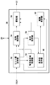
図2は、RR−ECU30の機能ブロックを示す図である。RR−ECU30は、センサ値受取部50、暫定基準値取得部52、保持制御部54、基準設定部56、駆動部58、基準値保有部60および駆動制御部62を備える。
FIG. 2 is a diagram illustrating functional blocks of the RR-
センサ値受取部50は、第1検出センサ33および第2検出センサ34からそれぞれの検出結果を受け取る。暫定基準値取得部52は、検出センサの任意の検出値をそのまま暫定基準値として記憶する。暫定基準値取得部52は、基準設定処理が完了していない場合に、第1検出センサ33により検出されたRRモータ32のロータの任意の回転位置を第1暫定基準値として記憶する。また、暫定基準値取得部52は、基準設定処理が完了していない場合に、第2検出センサ34により検出された検出値を第2暫定基準値として記憶する。第1暫定基準値および第2暫定基準値をとくに区別しない場合、暫定基準値という。暫定基準値は、検出センサにより検出された検出値の平均値であってもよい。
The sensor
車両にRRシステム35および後輪転舵ユニット41を組み付けてから車両を検査場に移動させる前の初期の組付状態において、後輪の舵角は略中点にあるため、暫定基準値取得部52はその状態における検出センサの検出値を暫定基準値として記憶する。これにより、後輪の舵角に関して初期の組付状態を記憶できる。たとえば、車両にRRシステム35を組み付けて、イグニッションスイッチがオンとなりRR−ECU30が起動した場合に、暫定基準値取得部52は、基準設定処理が完了していなければ第1検出センサ33からRRモータ32の回転位置を第1暫定基準値として取得する。第1暫定基準値は、初期の組付状態における第1検出センサ33が検出したRRモータ32の回転位置である。RRモータ32は、初期の組付状態において後輪の舵角の略中点に対応する状態で組み付けられる。
In the initial assembly state after the
保持制御部54は、基準設定処理が完了していない場合に、検出センサの検出値が暫定基準値となるようにRRモータ32を保持する制御をする。保持制御部54は、車両の移動時などに後輪から伝達される外力によってRRモータ32が回転しないように保持する制御信号を駆動部58に送出する。これにより、RRモータ32の回転を固定できる。保持制御部54は、少なくとも基準設定処理が完了した場合には、暫定回転位置でのRRモータ32の保持を解除する。なお、保持制御部54は、基準設定処理を開始した場合に暫定回転位置でのRRモータ32の保持を解除してよい。保持制御部54は、保持制御中に後輪が外力により転舵してRRモータ32が回転すると、検出センサの検出値が暫定基準値となるようにRRモータ32の回転位置を戻す制御をする。
The holding
具体的に保持制御中において保持制御部54は、RRモータ32をほぼリジッドな状態にしてRRモータ32が動作しないように制御しているものの、RRモータ32の回転位置が外力により変化すると、RRモータ32の回転位置を戻す。すなわち、保持制御部54は、RRモータ32が動作しても、暫定基準値取得部52より記憶した初期の組付状態にRRモータ32の状態を戻す制御をする。たとえば検出センサの検出値と暫定基準値との差の絶対値が所定の閾値を超えた場合に、保持制御部54は、検出センサの検出値が暫定基準値となるように、RRモータ32の回転位置を戻す制御をする。初期の組付状態ではECUの動作が不明であるため、一般的に学習処理を完了するまでRRモータ32などの駆動制御を実行しないが、実施形態ではRRモータ32に限って初期の組付状態を保つ駆動制御を実行する。これにより、基準設定処理においてRRアクチュエータ31および後輪転舵ユニット41の状態が初期の組付状態と同じくほぼ中立位置にあるため、効率よく学習処理を実行できる。
Specifically, during the holding control, the holding
駆動部58は、たとえばRRモータ32を駆動する駆動回路であって、保持制御部54および駆動制御部62から入力された制御信号に応じた駆動電流をRRモータ32に供給する。
The
基準設定部56は、後輪の所定の舵角に対して検出センサの基準値を設定する。検出センサの基準値は、検出センサの検出値と後輪の舵角との対応関係を示し、例えば舵角の中点(中立角)に設定され、操舵ハンドル10の中立位置と合うように設定される。基準設定部56は、RRモータ32が中立角から回転していた場合に、RRモータ32を強制的に駆動させて補正をして基準値を設定できる。基準設定部56は、基準値を設定すると完了フラグを立てて、基準値の情報を基準値保有部60に送出する。基準値保有部60は、基準設定部56により設定された基準値の情報を保有する。なお、基準値の情報は暫定基準値取得部52が保有する暫定基準値の情報とは異なる領域に記憶される。
The
駆動制御部62は、FR−ECU20から目標舵角を受け取って後輪の舵角を制御する。具体的に駆動制御部62は、第1検出センサ33および第2検出センサ34の検出値と、基準値保有部60が有する基準値の情報と、後輪の目標舵角とにもとづいて制御信号を生成し、駆動部58に制御信号を出力し、後輪の転舵を制御する。駆動制御部62は基準値を後輪舵角の中立角として制御する。
The
図3は、暫定基準設定処理を示すフローチャートである。本図に示す暫定基準設定処理は、周期的に実行される。暫定基準値取得部52は、IG(ignition switch)がオンされたか判定する(S10)。IGがオンされていなければ(S10のN)当該処理を終了し、IGがオンされていれば(S10のY)、暫定基準値取得部52は保持制御を実行する保持モード中であるか判定する(S12)。
FIG. 3 is a flowchart showing provisional reference setting processing. The provisional reference setting process shown in the figure is periodically executed. The provisional reference
保持モード中であれば(S12のY)当該処理を終了し、保持モード中でなければ(S12のN)、暫定基準値取得部52は基準設定処理が完了しているか判定する(S14)。基準設定処理が完了していれば(S14のY)、当該処理を終了する。基準設定処理が完了していなければ(S14のN)、暫定基準値取得部52はRRモータ32における暫定基準値を第1検出センサ33および第2検出センサ34から取得して記憶し(S16)、保持モードフラグを立てる(S18)。なお保持制御部54は、保持モードフラグが立つと、暫定基準値を用いて保持モードの制御を開始する。また保持制御部54は、基準設定処理が完了していれば保持モードフラグを下ろし、保持モードを終了する。このように、学習処理が完了するまでRRアクチュエータ31を初期の組付状態で保持することができ、基準設定処理の処理時間の増加を抑えることができる。
If it is in the holding mode (Y in S12), the process is terminated. If it is not in the holding mode (N in S12), the provisional reference
以上、実施の形態をもとに本発明を説明した。これらの実施形態は例示であり、各構成要素や各処理プロセスの組合せにいろいろな変形例が可能なこと、またそうした変形例も本発明の範囲にあることは当業者に理解されるところである。 The present invention has been described above based on the embodiment. It should be understood by those skilled in the art that these embodiments are exemplifications, and that various modifications can be made to the combination of each component and each processing process, and such modifications are also within the scope of the present invention.
実施形態では、暫定基準設定処理において、第1検出センサ33および第2検出センサ34の検出値の両方を暫定基準値として取得する態様を示したがこれに限られない。たとえば一方のセンサの検出値を暫定基準値として取得してもよく、第1検出センサ33の検出値がRRモータ32の初期の組付状態であるとして、暫定基準値として取得してよい。この態様においても学習処理が完了するまでRRアクチュエータ31の初期の組付状態を保持することができる。
In the embodiment, in the provisional reference setting process, an aspect in which both detection values of the
1 車両用操舵装置、 10 操舵ハンドル、 11 操舵入力軸、 12 転舵出力軸、 20 FR−ECU、 21 FRアクチュエータ、 22 FRモータ、 25 FRシステム、 30 RR−ECU、 31 RRアクチュエータ、 32 RRモータ、 33 第1検出センサ、 34 第2検出センサ、 35 RRシステム、 40 前輪転舵ユニット、 41 後輪転舵ユニット、 50 センサ値受取部、 52 暫定基準値取得部、 54 保持制御部、 56 基準設定部、 58 駆動部、 60 基準値保有部、 62 駆動制御部。
DESCRIPTION OF
Claims (4)
前記検出手段の検出値を暫定基準値として記憶する暫定基準値取得手段と、
前記暫定基準値取得手段が前記暫定基準値を記憶した後、前記検出手段の検出値を前記暫定基準値に保持するように制御する保持制御手段と、を備えることを特徴とする車両用操舵装置。 Detecting means for detecting a turning angle of a rear wheel of the vehicle;
Provisional reference value acquisition means for storing the detection value of the detection means as a provisional reference value;
The vehicle steering apparatus comprising: holding control means for controlling the detected value of the detecting means to be held at the temporary reference value after the temporary reference value acquiring means stores the temporary reference value. .
前記保持制御手段は、前記基準設定手段による前記検出手段の基準値の設定が完了した場合に、前記暫定基準値での保持を解除することを特徴とする請求項1に記載の車両用操舵装置。 Further comprising reference setting means for setting a reference value of the detection means for a predetermined steering angle of the rear wheel,
2. The vehicle steering apparatus according to claim 1, wherein the holding control unit releases the holding at the temporary reference value when the setting of the reference value of the detecting unit by the reference setting unit is completed. .
前記暫定基準値取得手段は、前記初期の組付状態においてイグニッションスイッチがオンとなった場合に、前記暫定基準値を取得することを特徴とする請求項1から3のいずれかに記載の車両用操舵装置。 In the initial assembly state in which the vehicle steering device is assembled to the vehicle, the steering angle of the rear wheel is substantially at the middle point,
4. The vehicle according to claim 1, wherein the provisional reference value obtaining unit obtains the provisional reference value when an ignition switch is turned on in the initial assembly state. 5. Steering device.
Priority Applications (1)
| Application Number | Priority Date | Filing Date | Title |
|---|---|---|---|
| JP2011277546A JP2013127429A (en) | 2011-12-19 | 2011-12-19 | Steering device for vehicle |
Applications Claiming Priority (1)
| Application Number | Priority Date | Filing Date | Title |
|---|---|---|---|
| JP2011277546A JP2013127429A (en) | 2011-12-19 | 2011-12-19 | Steering device for vehicle |
Publications (1)
| Publication Number | Publication Date |
|---|---|
| JP2013127429A true JP2013127429A (en) | 2013-06-27 |
Family
ID=48778041
Family Applications (1)
| Application Number | Title | Priority Date | Filing Date |
|---|---|---|---|
| JP2011277546A Pending JP2013127429A (en) | 2011-12-19 | 2011-12-19 | Steering device for vehicle |
Country Status (1)
| Country | Link |
|---|---|
| JP (1) | JP2013127429A (en) |
-
2011
- 2011-12-19 JP JP2011277546A patent/JP2013127429A/en active Pending
Similar Documents
| Publication | Publication Date | Title |
|---|---|---|
| JP4605265B2 (en) | Vehicle steering device | |
| WO2014136516A1 (en) | Electric power steering device | |
| US8229627B2 (en) | Vehicle steering apparatus | |
| US10759472B2 (en) | Steering controller | |
| US8855862B2 (en) | Vehicle steering system and loading vehicle | |
| JP2006123663A (en) | Steering control device | |
| JP2009220735A (en) | Electric power steering device | |
| JP2016088436A (en) | Motor control device | |
| US8938335B2 (en) | Control unit for vehicle steering system | |
| WO2017056975A1 (en) | Electric power steering device | |
| JP2007296900A (en) | Electric power steering device | |
| JP2007326460A (en) | Vehicle steering device | |
| JP6142659B2 (en) | Vehicle steering control device and vehicle steering control method | |
| JP2006347209A (en) | Steering device for vehicle | |
| JP6098352B2 (en) | Vehicle steering control device and vehicle steering control method | |
| JP2009029285A (en) | Vehicular steering device | |
| JP2015229385A (en) | Electric power steering device | |
| JP4553773B2 (en) | Electric power steering device | |
| JP6774315B2 (en) | Vehicle steering device | |
| JP7119311B2 (en) | steering controller | |
| JP5011785B2 (en) | Electric power steering device | |
| CN108216353B (en) | Vehicle control device | |
| JP5139700B2 (en) | Vehicle steering system | |
| JP2013127429A (en) | Steering device for vehicle | |
| JP6142660B2 (en) | Vehicle steering control device and vehicle steering control method |