JP2013120750A - Inductively-coupled plasma ion source for use with focused ion beam column with selectable ions - Google Patents
Inductively-coupled plasma ion source for use with focused ion beam column with selectable ions Download PDFInfo
- Publication number
- JP2013120750A JP2013120750A JP2012256982A JP2012256982A JP2013120750A JP 2013120750 A JP2013120750 A JP 2013120750A JP 2012256982 A JP2012256982 A JP 2012256982A JP 2012256982 A JP2012256982 A JP 2012256982A JP 2013120750 A JP2013120750 A JP 2013120750A
- Authority
- JP
- Japan
- Prior art keywords
- mass filter
- ion
- species
- plasma
- ions
- Prior art date
- Legal status (The legal status is an assumption and is not a legal conclusion. Google has not performed a legal analysis and makes no representation as to the accuracy of the status listed.)
- Pending
Links
Images


Classifications
-
- H—ELECTRICITY
- H01—ELECTRIC ELEMENTS
- H01J—ELECTRIC DISCHARGE TUBES OR DISCHARGE LAMPS
- H01J37/00—Discharge tubes with provision for introducing objects or material to be exposed to the discharge, e.g. for the purpose of examination or processing thereof
- H01J37/02—Details
- H01J37/04—Arrangements of electrodes and associated parts for generating or controlling the discharge, e.g. electron-optical arrangement, ion-optical arrangement
- H01J37/05—Electron or ion-optical arrangements for separating electrons or ions according to their energy or mass
-
- H—ELECTRICITY
- H01—ELECTRIC ELEMENTS
- H01J—ELECTRIC DISCHARGE TUBES OR DISCHARGE LAMPS
- H01J37/00—Discharge tubes with provision for introducing objects or material to be exposed to the discharge, e.g. for the purpose of examination or processing thereof
- H01J37/02—Details
- H01J37/04—Arrangements of electrodes and associated parts for generating or controlling the discharge, e.g. electron-optical arrangement, ion-optical arrangement
- H01J37/08—Ion sources; Ion guns
-
- H—ELECTRICITY
- H01—ELECTRIC ELEMENTS
- H01J—ELECTRIC DISCHARGE TUBES OR DISCHARGE LAMPS
- H01J37/00—Discharge tubes with provision for introducing objects or material to be exposed to the discharge, e.g. for the purpose of examination or processing thereof
- H01J37/30—Electron-beam or ion-beam tubes for localised treatment of objects
- H01J37/317—Electron-beam or ion-beam tubes for localised treatment of objects for changing properties of the objects or for applying thin layers thereon, e.g. for ion implantation
-
- H—ELECTRICITY
- H01—ELECTRIC ELEMENTS
- H01J—ELECTRIC DISCHARGE TUBES OR DISCHARGE LAMPS
- H01J2237/00—Discharge tubes exposing object to beam, e.g. for analysis treatment, etching, imaging
- H01J2237/006—Details of gas supplies, e.g. in an ion source, to a beam line, to a specimen or to a workpiece
-
- H—ELECTRICITY
- H01—ELECTRIC ELEMENTS
- H01J—ELECTRIC DISCHARGE TUBES OR DISCHARGE LAMPS
- H01J2237/00—Discharge tubes exposing object to beam, e.g. for analysis treatment, etching, imaging
- H01J2237/04—Means for controlling the discharge
- H01J2237/049—Focusing means
-
- H—ELECTRICITY
- H01—ELECTRIC ELEMENTS
- H01J—ELECTRIC DISCHARGE TUBES OR DISCHARGE LAMPS
- H01J2237/00—Discharge tubes exposing object to beam, e.g. for analysis treatment, etching, imaging
- H01J2237/05—Arrangements for energy or mass analysis
- H01J2237/057—Energy or mass filtering
-
- H—ELECTRICITY
- H01—ELECTRIC ELEMENTS
- H01J—ELECTRIC DISCHARGE TUBES OR DISCHARGE LAMPS
- H01J2237/00—Discharge tubes exposing object to beam, e.g. for analysis treatment, etching, imaging
- H01J2237/06—Sources
- H01J2237/08—Ion sources
-
- H—ELECTRICITY
- H01—ELECTRIC ELEMENTS
- H01J—ELECTRIC DISCHARGE TUBES OR DISCHARGE LAMPS
- H01J2237/00—Discharge tubes exposing object to beam, e.g. for analysis treatment, etching, imaging
- H01J2237/06—Sources
- H01J2237/08—Ion sources
- H01J2237/0815—Methods of ionisation
- H01J2237/0817—Microwaves
-
- H—ELECTRICITY
- H01—ELECTRIC ELEMENTS
- H01J—ELECTRIC DISCHARGE TUBES OR DISCHARGE LAMPS
- H01J2237/00—Discharge tubes exposing object to beam, e.g. for analysis treatment, etching, imaging
- H01J2237/06—Sources
- H01J2237/08—Ion sources
- H01J2237/0822—Multiple sources
- H01J2237/0827—Multiple sources for producing different ions sequentially
-
- H—ELECTRICITY
- H01—ELECTRIC ELEMENTS
- H01J—ELECTRIC DISCHARGE TUBES OR DISCHARGE LAMPS
- H01J2237/00—Discharge tubes exposing object to beam, e.g. for analysis treatment, etching, imaging
- H01J2237/30—Electron or ion beam tubes for processing objects
- H01J2237/303—Electron or ion optical systems
-
- H—ELECTRICITY
- H01—ELECTRIC ELEMENTS
- H01J—ELECTRIC DISCHARGE TUBES OR DISCHARGE LAMPS
- H01J2237/00—Discharge tubes exposing object to beam, e.g. for analysis treatment, etching, imaging
- H01J2237/30—Electron or ion beam tubes for processing objects
- H01J2237/317—Processing objects on a microscale
- H01J2237/31749—Focused ion beam
Abstract
Description
本発明は、荷電粒子ビーム処理システムに関し、具体的には選択可能なイオン種を有する荷電粒子ビーム・システムに関する。 The present invention relates to charged particle beam processing systems, and more particularly to charged particle beam systems having selectable ion species.
集束イオン・ビーム(FIB)システムは、集積回路製造分野およびナノテクノロジ分野のさまざまな用途において、マイクロスコピック構造およびナノスコピック構造を形成し、改変するために使用されている。FIBシステムは、さまざまな源を使用してイオンを生み出すことができる。例えば、液体金属イオン源(LMIS)は、高分解能処理、すなわち小さなスポット・サイズを提供することができるが、一般に小さなビーム電流を生み出す。 Focused ion beam (FIB) systems are used to form and modify microscopic and nanoscopic structures in various applications in the field of integrated circuit manufacturing and nanotechnology. FIB systems can produce ions using a variety of sources. For example, a liquid metal ion source (LMIS) can provide high resolution processing, ie a small spot size, but generally produces a small beam current.
ガリウムLMISを使用する一般的なシステムは、5から7ナノメートルの横方向分解能(lateral resolution)を提供することができる。そのようなシステムは、マイクロスコピックないしナノスコピック規模での材料の特性評価および処理で広く使用されている。ガリウムLMISは、ガリウムの層で覆われた先の尖った針を備える。源からイオンを引き出すために液体ガリウムに電場が与えられている間、この針は高温に維持される。 Typical systems using gallium LMIS can provide lateral resolution of 5 to 7 nanometers. Such systems are widely used in material characterization and processing on the microscopic or nanoscopic scale. Gallium LMIS comprises a pointed needle covered with a layer of gallium. The needle is maintained at an elevated temperature while an electric field is applied to the liquid gallium to extract ions from the source.
例えば、ガリウムLMISを有するFIBシステムを使用して、高い精度で画像化、ミリング、付着および分析を実行することができる。ミリングまたはマイクロ機械加工は、表面または表面近くのバルク材料の除去を含む。ミリングは、スパッタリングと呼ばれる運動量移動プロセスではエッチング支援ガスを使用せずに、または化学的支援(chemically−assisted)イオン・ビーム・エッチングと呼ばれるプロセスではエッチング支援ガスを使用して、実行することができる。本発明の譲受人に譲渡された米国特許第5,188,705号は、化学的支援イオン・ビーム・エッチング法を記載している。化学的支援イオン・ビーム・エッチングでは、イオン・ビームの存在下でエッチング強化ガスが反応して表面材料と結合し、揮発性の化合物を形成する。FIB付着では、イオン・ビームの存在下で有機金属化合物などの前駆体ガスが分解して、ターゲット表面に材料を付着させる。 For example, a FIB system with gallium LMIS can be used to perform imaging, milling, deposition and analysis with high accuracy. Milling or micromachining involves the removal of bulk material near or near the surface. Milling can be performed without using an etch assisting gas in a momentum transfer process called sputtering, or with an etching assisting gas in a process called chemically-assisted ion beam etching. . US Pat. No. 5,188,705, assigned to the assignee of the present invention, describes a chemically assisted ion beam etching process. In chemically assisted ion beam etching, the etch-enhancing gas reacts in the presence of the ion beam and combines with the surface material to form a volatile compound. In FIB deposition, a precursor gas such as an organometallic compound is decomposed in the presence of an ion beam to deposit the material on the target surface.
上記の全てのプロセスにおいて、ビーム中のガリウム・イオンの機能は、加工物の表面の粒子をスパッタリングによって物理的に追い出すためのエネルギー、または表面に付着した分子の化学反応を活性化させるためのエネルギーを供給することである。ガリウム自体は一般に反応には加わらない。ビーム中でガリウムが使用されるのは、融点、イオン化エネルギー、質量などのガリウムの特性が、一般的に使用されている加工物の材料と相互作用する細いビームを形成するのに適しているためである。ガリウムLMISを使用することには欠点もある。ガリウム原子は加工物の内部へ入り込み、多くの用途で、加工物の不透明度(opacity)または電気特性を変化させるなど望ましくない副作用を生み出す。ガリウムは、衝撃エリアの結晶構造を崩壊させることもある。さらに、非常に細いビームを生み出すためには、LMISからのビーム中の電流を比較的に低く保たなければならず、このことは、低いエッチング速度およびより長い処理時間を意味する。 In all of the above processes, the function of the gallium ions in the beam depends on the energy to physically expel particles on the surface of the workpiece by sputtering or to activate the chemical reaction of molecules attached to the surface. Is to supply. Gallium itself generally does not participate in the reaction. Gallium is used in the beam because the properties of gallium, such as melting point, ionization energy, and mass, are suitable for forming narrow beams that interact with commonly used workpiece materials. It is. There are drawbacks to using gallium LMIS. Gallium atoms penetrate into the workpiece and produce undesirable side effects in many applications, such as changing the opacity or electrical properties of the workpiece. Gallium may disrupt the crystal structure of the impact area. Furthermore, in order to produce a very narrow beam, the current in the beam from the LMIS must be kept relatively low, which means a low etch rate and a longer processing time.
異なる用途に対しては異なるイオン種を使用することが望ましいと思われるが、液体金属イオン源は、生み出すことができるイオンの種類が限られている。適当な融点、イオン化エネルギーおよび質量を有する金属種だけを使用することができ、このことは、LMISから利用可能なイオン種を限定する。異なる処理ステップに対してイオン種を迅速に変更することができることも望ましいと思われるが、LMISのイオン種を変更するには、真空室から源を除去し、代わりに異なる源を配置する必要があり、それには、時間のかかる調製手順を経なければならない。2種類以上の金属のイオンを供給する液体金属合金源もある。このような源から利用可能なイオンの種類は、適当な特性を有する合金を形成する金属の組合せに限定される。Parker他の「Method for Repairing Semiconductor Masks & Reticles」という名称の米国特許第5,165,954号に記載されているものなど、いくつかの液体金属合金系が質量フィルタ(mass filter)とともに使用されており、その質量フィルタは、異なる種のイオンを分離して、ターゲットに衝突するビームが単一の種を含むようにする。 While it may be desirable to use different ionic species for different applications, liquid metal ion sources have a limited number of ions that can be produced. Only metal species with an appropriate melting point, ionization energy and mass can be used, which limits the ionic species available from LMIS. It would also be desirable to be able to quickly change the ion species for different processing steps, but changing the ion species of the LMIS would require removing the source from the vacuum chamber and placing a different source instead. Yes, it must go through a time-consuming preparation procedure. There are also liquid metal alloy sources that supply ions of two or more metals. The types of ions available from such sources are limited to combinations of metals that form alloys with suitable properties. Several liquid metal alloy systems have been used with mass filters, such as those described in US Pat. No. 5,165,954, entitled “Method for Recycling Semiconductor Masks & Reticles” by Parker et al. The mass filter separates different species of ions so that the beam impinging on the target contains a single species.
E×Bフィルタないし「ウィーン・フィルタ(Wien filter)」などのいくつかのタイプの質量フィルタは電場および電場に垂直な磁場を使用し、この電場および磁場は、選択された質量およびエネルギーのイオンはフィルタを通過させるが、他の質量またはエネルギーを有するイオンはバリヤ内へ偏向させる。E×Bフィルタの偏向はイオンのエネルギーに依存し、ビーム中のエネルギーは常にある程度は変動しており、そのためE×Bフィルタは、ビームを広げ、ビームの分解能を低下させる色収差をシステムに導入する。質量フィルタ内の不均一な場もビーム収差に寄与する。 Some types of mass filters, such as an E × B filter or “Wien filter”, use an electric field and a magnetic field perpendicular to the electric field, which are ions of the selected mass and energy. While passing through the filter, ions with other masses or energies are deflected into the barrier. The deflection of the E × B filter depends on the energy of the ions, and the energy in the beam is always fluctuating to some extent, so the E × B filter introduces chromatic aberration into the system that widens the beam and reduces the resolution of the beam. . Non-uniform fields in the mass filter also contribute to beam aberration.
プラズマ・イオン源は、プラズマ室内のガスをイオン化し、イオンを引き出して、加工物の表面に集束させるビームを形成する。CoathおよびLong、「A High−Brightness Duoplasmatron Ion Source Microprobe Secondary Ion Mass Spectroscopy」、Rev.Sci.Instruments 66(2)、1018ページ(1995)に記載されているデュオプラズマトロン(duoplasmatron)プラズマ・イオン源などのプラズマ・イオン源は、イオン・ビーム・システム用のイオン源として、特に質量分析用途およびイオン注入用途に使用されている。プラズマ室から引き出されるイオンのエネルギー幅のため、デュオプラズマトロン源のイオンを、LMISからのイオンと同様の小さなスポットに集束させることはできない。デュオプラズマトロン・イオン源は例えば、大面積にわたってイオンを注入する目的または飛行時間質量分析に対して使用されている。飛行時間質量分析では、1次ビーム中のイオンが表面からイオンをスパッタリングし、スパッタリングされたイオンが検出器に到達するのに要した時間によって、スパッタリングされたそれぞれのイオンの質量が決定される。正確な測定値を得るためには、1次ビーム中のイオンが表面に衝突した時刻を正確に知る必要がある。多くのガス種は、質量がわずかに異なる複数の同位体からなり、1次ビーム中の異なる同位体は異なる時刻に試料に到達するため、同位体を分離して、正確に分っている時刻に単一の同位体が試料に到達するようにするために、質量フィルタリングが使用されている。 The plasma ion source ionizes the gas in the plasma chamber, extracts the ions, and forms a beam that is focused on the surface of the workpiece. Coath and Long, “A High-Brightness Duoplasmatron Ion Source Microprobe Secondary Ion Mass Spectroscopy”, Rev. Sci. Plasma ion sources, such as the duoplasmatron plasma ion source described in Instruments 66 (2), page 1018 (1995), are particularly useful as mass spectrometry applications and ion sources for ion beam systems. Used for ion implantation. Due to the energy width of the ions extracted from the plasma chamber, the duoplasmatron source ions cannot be focused into a small spot similar to the ions from the LMIS. Duoplasmatron ion sources are used, for example, for the purpose of implanting ions over a large area or for time-of-flight mass spectrometry. In time-of-flight mass spectrometry, the mass of each sputtered ion is determined by the time it takes for the ions in the primary beam to sputter ions from the surface and the sputtered ions reach the detector. In order to obtain an accurate measurement value, it is necessary to accurately know the time when the ions in the primary beam collide with the surface. Many gas species consist of multiple isotopes with slightly different masses, and the different isotopes in the primary beam arrive at the sample at different times, so the isotopes are separated and accurately known Mass filtering is used to ensure that a single isotope reaches the sample.
最近、FIBシステム内で誘導結合プラズマ(inductively coupled plasma)(ICP)イオン源が使用され始めた。ICP源の技術革新は色収差を低減させ、色収差の低減は、より高分解能の処理を可能にし、画像化を含むイオン・ビーム処理に対する新たな可能性への道を開いた。 Recently, inductively coupled plasma (ICP) ion sources have begun to be used in FIB systems. ICP source innovation has reduced chromatic aberration, which has allowed for higher resolution processing and opened the way for new possibilities for ion beam processing, including imaging.
プラズマ・イオン源では、多くの異なる種類のガスを使用してさまざまなイオン種を生み出すことができ、そのため、異なる用途に対してイオン種を最適化することができる。例えば、ヘリウム・イオンは、画像化または軽い研磨に対して有用であり、キセノン・イオンは、バルク処理に対して有用なより高いミリング速度を提供する。プラズマ・イオン源は、多くの異なる種類のイオンをより大きな電流で生み出すことができるが、ビーム分解能は限定されていた。ユーザがプラズマ源内のイオン種を変更したいときには、プラズマ室から第1のガスを除去し、代わりに第2のガスを導入する必要がある。本発明の譲受人に譲渡され、参照によって本明細書に組み込まれる「Multi−Source Plasma Focused Ion Beam System」という名称の米国特許出願公開第2009/0309018号は、異なる荷電粒子ビーム操作を実行するために、複数のガスをプラズマ室へ供給して異なるイオン種を生み出すシステムを記載している。残念なことに、プラズマ室から1つのガスを除去し、プラズマ室に第2のガスを充填するのには最長30分かかることがある。プラズマ室内の圧力を維持するため、プラズマ・イオン源のガス入口は一般に、そこを通してガスを供給する小さな開口を有する。このガスは非常にゆっくりと使用されるため、ガスを補充するためのこの小さな開口は非常に小さい。このことは、異なるプロセス・ガスを逐次的に使用して加工物を処理する多くの用途にとって、ガスの交換を、容認しがたい長い時間にする。 In a plasma ion source, many different types of gases can be used to generate a variety of ion species, so that the ion species can be optimized for different applications. For example, helium ions are useful for imaging or light polishing, and xenon ions provide higher milling rates useful for bulk processing. Plasma ion sources can produce many different types of ions at higher currents, but have limited beam resolution. When the user wants to change the ion species in the plasma source, it is necessary to remove the first gas from the plasma chamber and introduce a second gas instead. US Patent Application Publication No. 2009/0309018, entitled “Multi-Source Plasma Focused Ion Beam System”, assigned to the assignee of the present invention and incorporated herein by reference, is intended to perform different charged particle beam operations. Describes a system for generating different ionic species by supplying a plurality of gases to a plasma chamber. Unfortunately, it can take up to 30 minutes to remove one gas from the plasma chamber and fill the plasma chamber with a second gas. In order to maintain the pressure in the plasma chamber, the gas inlet of the plasma ion source typically has a small opening through which gas is supplied. Since this gas is used very slowly, this small opening for refilling the gas is very small. This makes gas exchange unacceptably long for many applications that use different process gases sequentially to process the workpiece.
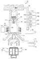
図1は、米国特許出願公開第2009/0309018号に記載されたFIBシステムなどのFIBシステム用の一般的な先行技術のICPイオン源100を示す。ガスは、外部のガス供給管路104からガス・フィルタ106を通して源管103内のプラズマ室102へ供給され、次いで流れ絞り110を備える毛管108へ供給される。エネルギーは、RF電源113からアンテナ・コイル114によってプラズマ室102内へ供給され、イオンは、引出し電極120によって、源電極118の源電極絞り116を通して引き出される。分割ファラデー・シールド121は、コイル114と室102内のプラズマとの間の容量結合を低減させ、この容量結合の低減は、引き出されるイオンのエネルギー幅を低減させる。電源113は、アンテナ114を「平衡した(balanced)」形で駆動することが好ましい。すなわち、本発明の譲受人に譲渡され、参照によって本明細書に組み込まれるKeller他の「Magnetically enhanced,inductively coupled plasma source for a focused ion beam system」という名称の米国特許出願公開第2008/0017319号に記載されているように、アンテナを横切る電気的な移相が、プラズマ電位の変調を低減させるように調整される。この平衡アンテナは、プラズマ内の高周波エネルギー場のヌル・ポイント(null point)を提供することが好ましく、このことは、プラズマ室102から引き出されるイオンのエネルギー幅を低減させる。
FIG. 1 shows a typical prior art
プラズマ室102内へ入り、プラズマ室102を出るガス・コンダクタンス(gas conductance)は、(源管103の頂部の)毛管内の流れ絞り110および源電極118の絞り116(一般に直径1/4mm未満)を通る。弁123を介してガス供給管路104に接続されたポンプ122が、毛管108およびガス供給管路104を通してプラズマ室102からガスを除去する。イオン・カラム・ポンプ(図示せず)が、源電極絞り116を通してプラズマ室102からガスを引き出す。ガス貯蔵容器130A、ガス貯蔵容器130B、ガス貯蔵容器130Cおよびガス貯蔵容器130Dなどの複数のガス源が、対応する弁131Aから131Dを介してガス供給管路104内へガスを供給する。ビーム電圧源132は室102内のプラズマに高電圧を印加し、引出し電圧源134は引出し電極120に電圧を印加する。引き出されたイオンまたは電子は集束電極136によって集束する。集束カラムおよび試料室の追加の詳細は示されていない。
The gas conductance entering and exiting the
プラズマ室の内部からガスを除去するため、ガス供給管路104を示されているようにポンピングして、毛管108の流れ絞り110の上方の源管内のガスを除去する。源電極118の下方のFIBシステムの容積も、主室真空ポンプ(1つまたは複数)(図示せず)を使用して適切にポンピングすることができる。
To remove gas from the interior of the plasma chamber, the
源電極絞り116と流れ絞り110の直径はともに小さく、それに対応してガス・コンダクタンスも非常に低いため、源管103の内部のガスをポンプによって迅速に排出することは不可能である。このことは特に、異なるイオン種を用いて逐次プロセス・ステップを実行することが時に望ましい製造FIBシステムにおいて不利である。第1に、ベース圧力が、第2のプロセス・ガスを導入するのに十分に低い圧力になるまで源管103から第1のプロセス・ガスをポンプによって排出するのに、はるかに長い時間がかかることがある。ガスの不十分なパージは、そのガスがイオン化することによってプラズマの汚染につながることがある。「Methods and Structures for Rapid Switching between Different Process Gases in an Inductively−Coupled Plasma(ICP)Ion Source」という名称の米国特許出願第13/182,187号は、ガスが真空室に入るための代替経路またはガスが真空室から出るための代替経路を提供することによって、プラズマ源内のガスを迅速に変更することを可能にするプラズマ室設計を記載している。
Since the diameters of the
このように、異なるイオン種の高分解能ビームの提供は、長いガス交換時間によって制限を受け、または金属合金源の場合には、合金中に存在する金属によって制限を受けるが、合金中に存在する金属は一般に、材料の両立性に基づいてそのような合金を生み出す能力によって制限される。 Thus, the provision of high resolution beams of different ionic species is limited by long gas exchange times, or in the case of metal alloy sources, limited by the metal present in the alloy, but present in the alloy. Metals are generally limited by their ability to produce such alloys based on material compatibility.
本発明の目的は、異なるイオン種を迅速に切換えるFIBシステムを提供することにある。 It is an object of the present invention to provide an FIB system that can quickly switch between different ionic species.
本発明の好ましい一実施形態によれば、FIBカラム用のICPイオン源が提供される。このプラズマ・イオン源は、異なる種のイオンを供給するために2種類以上のガスを含む。集束ビームを構成するイオン種は、源を出た複数のイオン種の中から質量フィルタを使用して選択される。 According to a preferred embodiment of the present invention, an ICP ion source for an FIB column is provided. The plasma ion source includes two or more gases to supply different species of ions. The ion species that make up the focused beam are selected from a plurality of ion species leaving the source using a mass filter.
以上では、以下の本発明の詳細な説明をより十分に理解できるように、本発明の特徴および技術上の利点をかなり広く概説した。以下では、本発明の追加の特徴および利点を説明する。開示される着想および特定の実施形態を、本発明の同じ目的を達成するために他の構造を変更しまたは設計するベースとして容易に利用することができることを当業者は理解すべきである。さらに、このような等価の構造は、添付の特許請求の範囲に記載された本発明の趣旨および範囲を逸脱しないことを当業者は理解すべきである。 The foregoing has outlined rather broadly the features and technical advantages of the present invention in order that the detailed description of the invention that follows may be better understood. The following describes additional features and advantages of the present invention. It should be understood by those of ordinary skill in the art that the disclosed concepts and specific embodiments can be readily utilized as a basis for modifying or designing other structures to accomplish the same objectives of the present invention. Moreover, those skilled in the art should appreciate that such equivalent constructions do not depart from the spirit and scope of the invention as set forth in the appended claims.
次に、本発明および本発明の利点のより完全な理解のため、添付図面に関して書かれた以下の説明を参照する。 For a more complete understanding of the present invention and its advantages, reference is now made to the following description, taken in conjunction with the accompanying drawings.
好ましい一実施形態は、複数のガス種を含むICPイオン源と、源から引き出された複数のイオン種の中から、集束イオン・ビームとしてターゲットに衝突する1つのイオン種を選択する質量フィルタとを備える。この好ましい実施形態は、ほぼ制限のないさまざまな用途で使用される質量およびビーム電流の非常に広い選択範囲を提供する。これは、例えば質量がわずかに異なる複数の同位体の中から単一の種が選択される飛行時間質量分析における質量フィルタリングとは異なる。ICP源と質量フィルタの組合せは、高分解能ビームと、選択可能なイオン種の幅広い選択間の迅速な切換えとを同時に提供する課題に対する解答を提供する。質量フィルタは、ビーム形成中に異なる種のイオンが源を出、質量フィルタによって特定の種が選択され、他の種は拒絶されることを可能にする。動作中、プラズマ中には複数のガスが存在しているため、単純に質量フィルタの構成を変更することによって、1分未満、1秒未満、0.5秒未満または0.1秒未満のうちにイオン種を迅速に変更することができる。 One preferred embodiment includes an ICP ion source including a plurality of gas species, and a mass filter that selects one ion species that impinges on the target as a focused ion beam from the plurality of ion species extracted from the source. Prepare. This preferred embodiment provides a very wide selection of mass and beam currents used in a variety of applications with almost no limitations. This is different from mass filtering in time-of-flight mass spectrometry where, for example, a single species is selected from a plurality of isotopes with slightly different masses. The combination of ICP source and mass filter provides an answer to the problem of simultaneously providing a high resolution beam and a rapid switch between a wide selection of selectable ion species. Mass filters allow different species of ions to be sourced during beam formation, certain species are selected by the mass filter, and other species are rejected. During operation, there are multiple gases in the plasma, so by simply changing the configuration of the mass filter, less than 1 minute, less than 1 second, less than 0.5 seconds or less than 0.1 seconds The ion species can be changed quickly.
好ましい1つの質量フィルタがウィーン・フィルタであり、ウィーン・フィルタは、磁場および磁場に対して垂直な電場を有する領域の中をビームが移動するためE×Bフィルタとも呼ばれている。4重極、扇形機器(a sector instrument)、球面コンデンサなど、他のタイプの質量フィルタを使用することもできる。ICPプラズマ源およびE×B質量フィルタは、混合された源ガスと組み合わされたときに、全ての源ガスからのイオンを同時に含むプラズマを発生させる方法を提供する。これらのガスは、予め混合されたガスの源から固定された比率で、または個々のガス源から選択可能な比率でプラズマ室内へ導入することができる。プラズマ室内の混合ガスは、汚染の結果でもまたは同じ元素の異なる同位元素の結果でもなく、異なる元素を含み、それらの元素はそれぞれ、プラズマ中に、加工物を処理するビームを形成するのに十分な量で存在する。 One preferred mass filter is a Wien filter, which is also referred to as an E × B filter because the beam moves in a magnetic field and a region having an electric field perpendicular to the magnetic field. Other types of mass filters can be used, such as quadrupoles, sector instruments, spherical capacitors, and the like. The ICP plasma source and the E × B mass filter provide a method for generating a plasma that simultaneously contains ions from all source gases when combined with a mixed source gas. These gases can be introduced into the plasma chamber in a fixed ratio from a premixed gas source or in a selectable ratio from individual gas sources. The gas mixture in the plasma chamber contains different elements, neither as a result of contamination or as a result of different isotopes of the same element, each of which is sufficient to form a beam in the plasma to process the workpiece. Present in the correct amount.
E×Bフィルタは、色収差および他の収差をビームに導入することが知られているが、質量フィルタを通過したビームおよび集束カラムに導入される収差を小さくし、それによって小さなスポット・サイズおよび高分解能処理を提供するのに、ICPプラズマ源を出るイオン間のエネルギーの変動は十分に小さいことを本出願の出願人は見出した。好ましいICPは、40eV未満、より好ましくは20eV未満、最も好ましくは6eV未満のエネルギー幅を有する同じ種のイオンを生み出す。ICPプラズマ源、質量フィルタおよびイオン・カラムの組合せは、1ミクロン未満、500nm未満、100nm未満または50nm未満のスポット・サイズを有するイオン・ビームを提供することができる。ICPと質量フィルタの組合せによって提供される加工物の位置におけるビーム電流は一般に1pAから10μAの間である。一実施形態では、ICPプラズマ源と質量フィルタの組合せが、200μm未満、500nm未満または100nm未満のスポット・サイズを有する電流10μAのビームを提供することができる。他の実施形態では、ICPプラズマ源との組合せが、500nm未満、100nm未満または50nm未満のスポット・サイズを有する電流1μAのビームを提供することができる。他の実施形態では、ICPプラズマ源との組合せが、200nm未満、100nm未満または25nm未満のスポット・サイズを有する電流10nAのビームを提供することができる。他の実施形態では、ICPプラズマ源との組合せが、20nm未満、10nm未満または5nm未満のスポット・サイズを有する電流1pAのビームを提供することができる。ビーム分解能は、レンズ・モード動作、源内の分割ファラデー・シールドおよび平衡アンテナならびにさまざまな技法をさまざまに組み合わせて質量フィルタ内の収差を低減させることによって向上する。特定の用途に対して必要な分解能によっては、全ての実施形態で、分解能を向上させるこれらの全ての諸特徴が使用されるわけではない。 ExB filters are known to introduce chromatic and other aberrations into the beam, but reduce the aberrations introduced into the beam that has passed through the mass filter and into the focusing column, thereby reducing the spot size and height. Applicants have found that the variation in energy between ions exiting the ICP plasma source is small enough to provide resolution processing. Preferred ICPs produce ions of the same species having an energy width of less than 40 eV, more preferably less than 20 eV, and most preferably less than 6 eV. The combination of ICP plasma source, mass filter and ion column can provide an ion beam having a spot size of less than 1 micron, less than 500 nm, less than 100 nm, or less than 50 nm. The beam current at the workpiece location provided by the ICP and mass filter combination is typically between 1 pA and 10 μA. In one embodiment, an ICP plasma source and mass filter combination can provide a 10 μA current beam with a spot size of less than 200 μm, less than 500 nm, or less than 100 nm. In other embodiments, a combination with an ICP plasma source can provide a beam of 1 μA current with a spot size of less than 500 nm, less than 100 nm, or less than 50 nm. In other embodiments, a combination with an ICP plasma source can provide a 10 nA beam with a spot size of less than 200 nm, less than 100 nm, or less than 25 nm. In other embodiments, a combination with an ICP plasma source can provide a beam with a current of 1 pA having a spot size of less than 20 nm, less than 10 nm, or less than 5 nm. Beam resolution is improved by various combinations of lens mode operation, split Faraday shield and balanced antenna in the source, and various techniques to reduce aberrations in the mass filter. Depending on the resolution required for a particular application, not all of these features that improve resolution are used in all embodiments.
E×Bフィルタは、混合された源の中から1つのイオン種を選択しまたは拒絶して、特定のイオン、例えば軽いイオン、より重いイオン、不活性イオンまたは反応性イオンを使用することによって利益を得る特定の操作を実行することを可能にする。一実施形態は、ネオン、アルゴンおよびキセノンなどの非常に軽いイオン、中程度の重さのイオンおよび重いイオンの混合ガスを使用し、この混合ガスは、広範囲のイオン質量が広範囲の用途をカバーすることを可能にする。 The E × B filter benefits by selecting or rejecting one ionic species from a mixed source and using specific ions, such as light ions, heavier ions, inert ions or reactive ions. Allows you to perform certain operations. One embodiment uses a mixture of very light ions such as neon, argon and xenon, moderately heavy ions and heavy ions, which has a wide range of ion masses covering a wide range of applications. Make it possible.
いくつかの実施形態では、プラズマ源へ導入する前に外部の共通のプレナム内で別個のガスを予め混合することによって、ガスの組成および/または比率が制御される。この共通のプレナムは次いでガス供給管路を介してイオン源に接続される。他の実施形態では、それぞれが単一のガス種を含む複数の個々のガス源からガス供給管路へガスが接続される。実施形態は、所望の1つの種の性能を他の種よりも優先して高めることができ、同時に、質量フィルタの使用によってイオン種の選択能力を依然として維持することができる広範囲の電力設定および圧力設定を可能にする。例えば、酸素、キセノンなどの異なるガスを可変の化学量論組成で混合することができ、異なる電力および圧力設定での動作によってそれらをさらに最適化することができる。一般に、ガス圧の下限は、最も制限的なガスに対する高電圧破壊に対応する圧力によって規定される。数多くの特定のガス種に対して固有の電力と圧力の関係が存在することは、パッシェン(Paschen)による徹底的な特性評価によって確立されている。この関係は、そのガスの高電圧破壊を生じない規定されたある電圧およびある圧力範囲内におけるそのガスの許容可能な作用範囲を定義する。質量フィルタリングによって、または電力および圧力の細かな調節ならびに追加の質量フィルタリングによって優先的に選択可能な同じプラズマ源内の広範囲のガス種またはガス種の組合せに対して源ガス、動作圧力および電力設定のさまざまな組合せが達成可能であることを当業者は理解するであろう。 In some embodiments, the gas composition and / or ratio is controlled by premixing separate gases in an external common plenum prior to introduction into the plasma source. This common plenum is then connected to the ion source via a gas supply line. In other embodiments, gas is connected from a plurality of individual gas sources, each containing a single gas species, to a gas supply line. Embodiments have a wide range of power settings and pressures that can enhance the performance of a desired species over other species, while still maintaining the ability to select ionic species through the use of mass filters Enable setting. For example, different gases such as oxygen, xenon, etc. can be mixed with variable stoichiometry, and they can be further optimized by operation with different power and pressure settings. In general, the lower limit of gas pressure is defined by the pressure corresponding to the high voltage breakdown for the most restrictive gas. The existence of inherent power and pressure relationships for many specific gas species has been established by thorough characterization by Paschen. This relationship defines an acceptable working range of the gas within a specified voltage and pressure range that does not cause high voltage breakdown of the gas. Variety of source gas, operating pressure and power settings for a wide range of gas species or combinations of gas species within the same plasma source that can be preferentially selected by mass filtering or by fine adjustment of power and pressure and additional mass filtering One skilled in the art will appreciate that various combinations are achievable.
上記の例では、最も制限的なガスが、高電圧破壊が起こる前の最小入口圧力要件が約1300ミリバールであるキセノンである。反対に、酸素は、約500ミリバールのはるかに低い限界を有する。さらに、プラズマを生み出し持続させるために必要な、源ガス種に基づく最小電力設定が存在する。例えば、キセノンは、15Wという低い投入電力でプラズマを持続させることができるが、酸素は、約150Wの最小投入電力を必要とする。キセノンと酸素の混合物は、追加の質量フィルタリングとともに、または単純に電力および圧力パラメータを細かく調節することによって独立して作用させることができる。このような源ガスの組合せを作用させるための電力および圧力の一般的な範囲は、500ミリバールから3000ミリバールの間の圧力で25Wから1000Wである。電力および圧力のより好ましい範囲は、100Wから600Wおよび1000ミリバールから2000ミリバールとすることができる。または反対に、電力を25Wから100Wに設定し、圧力を1500ミリバールから2000ミリバールに設定することによって、酸素の存在下であってもキセノン・プラズマだけを優先的に発生させ、パッシェン破壊を生じさせないことができるであろう。いずれにしても、質量フィルタの存在は、プラズマ・ビームが引き出され集束した後に、プラズマ・ビームの不必要な成分を除去することを可能にする。ネオンなどの軽いイオン種から、アルゴンなどの中程度の重さのイオン種およびキセノンなどの重いイオン種に至るまでの広範囲の源ガス種の作用が実証されている。窒素、酸素などの他の源ガスも実証されている。したがって、これらのガスの任意の組合せを用いて、記載した方法によって、プラズマ源および質量フィルタを機能させることが可能であるはずである。したがって、この実施態様は、迅速な材料除去から軽いイオンによる画像化に至るまでのさまざまな用途に対して、大きな汎用性、正確な選択および使いやすさを可能にする。上記の情報をガイダンスとして使用して、当業者は、ガスのさまざまな組合せに対して適当な電力と圧力の関係を選択することができる。 In the above example, the most restrictive gas is xenon with a minimum inlet pressure requirement of about 1300 mbar before high voltage breakdown occurs. In contrast, oxygen has a much lower limit of about 500 mbar. In addition, there is a minimum power setting based on the source gas species that is required to create and sustain the plasma. For example, xenon can sustain a plasma with an input power as low as 15W, while oxygen requires a minimum input power of about 150W. The mixture of xenon and oxygen can be operated independently with additional mass filtering or simply by fine-tuning the power and pressure parameters. A typical range of power and pressure for operating such a source gas combination is 25 W to 1000 W at a pressure between 500 mbar and 3000 mbar. More preferred ranges of power and pressure can be 100 W to 600 W and 1000 mbar to 2000 mbar. Or conversely, by setting the power from 25 W to 100 W and the pressure from 1500 mbar to 2000 mbar, only xenon plasma is preferentially generated even in the presence of oxygen, and no Paschen breakdown occurs. Would be able to. In any case, the presence of the mass filter makes it possible to remove unwanted components of the plasma beam after it has been extracted and focused. The effects of a wide range of source gas species have been demonstrated, ranging from light ionic species such as neon to moderately heavy ionic species such as argon and heavy ionic species such as xenon. Other source gases such as nitrogen and oxygen have also been demonstrated. Thus, it should be possible to make the plasma source and mass filter work by the described method using any combination of these gases. This embodiment thus allows great versatility, accurate selection and ease of use for a variety of applications ranging from rapid material removal to light ion imaging. Using the above information as guidance, one skilled in the art can select appropriate power and pressure relationships for various combinations of gases.
複数のガスをプラズマ室へどのように供給するかにかかわらず、実施形態は、イオン種の即時の選択を可能にする。さもなければ、特定の作用のために必要なイオン種を変更するために源ガスの交換が必要となるであろう。 Regardless of how multiple gases are supplied to the plasma chamber, embodiments allow for immediate selection of ionic species. Otherwise, source gas exchange may be required to change the ionic species required for a particular action.
いくつかの実施形態の利点は、予め混合されるにせよ、またはガス供給管路もしくはプラズマ室内で混合されるにせよ、数多くのガス混合物を送達することができることである。このことは、1つの源アセンブリ内の複数の合金源を作用させることができることに似ている。例えば、あるガス源は、ヘリウムおよびキセノンとすることができる混合物を供給することができ、他のガス源は、水素および酸素とすることができる混合物を供給することができる。いくつかの実施形態では、例えば本発明の譲受人に譲渡され、参照によって本明細書に組み込まれるRue他の「Navigation and Sample Processing Using an Ion Source Containing both Low−Mass and High−Mass Species」という名称の米国特許出願第13/223,276号に記載されているように軽いイオンによる画像化と重いイオンによるミリングの同時実施に使用するため、より多くの複数のイオン種を通過させるように、1つまたは複数の質量フィルタを設定することができる。 An advantage of some embodiments is that many gas mixtures can be delivered, whether premixed or mixed in a gas supply line or plasma chamber. This is similar to the ability to actuate multiple alloy sources within a single source assembly. For example, one gas source can supply a mixture that can be helium and xenon, and another gas source can supply a mixture that can be hydrogen and oxygen. In some embodiments, for example, Rue et al. “Navigation and Sample Processing using an Ion Source Containing boh Low-Mass and High-Mass Species”, which is assigned to the assignee of the present invention and incorporated herein by reference. US Pat. No. 13 / 223,276 of US patent application Ser. No. 13 / 223,276, for use in simultaneous imaging of light ions and milling with heavy ions, One or more mass filters can be set.
いくつかの実施形態の追加の利点は、ICP源が、極めて広い範囲のビーム電流を送達することができることであり、それによって利用可能な質量の幅広い分布、ならびにそれらの質量の非常に異なる画像化特性およびミリング特性をさらに利用することができることである。 An additional advantage of some embodiments is that the ICP source can deliver a very wide range of beam currents, thereby wide distribution of available masses, as well as very different imaging of those masses. The properties and milling properties can be further utilized.
本発明の出願人は、プラズマ室内のガスとして空気を使用する実施形態の能力を実証した。プラズマは主に窒素イオンからなり、残りの部分は主に酸素イオンからなり、アルゴン、ヘリウムなどの他の元素を小さな割合で含むであろう。 Applicants of the present invention have demonstrated the ability of embodiments to use air as the gas in the plasma chamber. The plasma will consist mainly of nitrogen ions and the rest will mainly consist of oxygen ions and will contain a small percentage of other elements such as argon, helium.
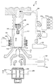
図2Aは、本発明のFIBシステム200を示す。システム200は図1のシステム100と類似しているが、イオン源の下方に質量フィルタ202が追加されている。図1と同様に、好ましいプラズマ源は、アンテナとプラズマの間の容量結合を低減させ、引き出されるイオンのエネルギー幅を低減させるために分割ファラデー・シールド121を含む。好ましいプラズマ源はさらに、アンテナを横切る移相を、プラズマ電位の高周波変調を最小化しまたは排除するように調整する、平衡した形で駆動されるアンテナ114を含む。質量フィルタ202はE×Bフィルタであることが好ましいが、他のタイプの質量フィルタを使用することもできる。質量フィルタ202は、電場を提供する電極204と、図の平面の前方および後方に配置されて交差磁場を提供する磁石(図示せず)とを含む。コネクタ206は、電極204への電気接続と、電極204の位置を調整する機械的な接続とを提供する。これらの電場および磁場は、偏向させずにフィルタを通過させ、さらにビーム経路上の絞りを通過させるイオンの質量を選択するように調整可能であり、選択された質量以外の質量を有するイオンは偏向し、絞りを通過しない。質量フィルタ202は概略的に示されているが、質量フィルタ202は、より複雑な質量フィルタ、またはビーム軸に沿って分離された2つ以上のE×B場領域を有する複合フィルタを含むことができる。弁131Aから131Dは、プラズマ室106へガスを供給するガス供給管路104内へ所望のガス混合物を供給するように調整される。いかなるときでも一般に単一のガスがプラズマ室102へ供給される先行技術とは違い、本発明の実施形態では、弁131Aから131Dのうちの複数の弁を同時に開いて、複数のガス種をプラズマ室へ同時に供給することができる。弁131Aから131Dは、ガス入口104へ入るガスの比率を制御するメータリング・バルブ(metering valve)であることが好ましい。
FIG. 2A shows the FIB system 200 of the present invention. The system 200 is similar to the
図2Bは、図2Aと類似しているが、ガス供給源130Aから130Dのうちの一部のガス供給源が弁131Aから131Dを通して混合プレナム210にガスを供給する点が異なる。ガスは、混合プレナム210内で予め混合され、その後、弁212を通ってガス供給管路104およびプラズマ室102へ入る。ガス供給源130Eは、ガス供給管路104内へガスを直接に供給する。さまざまな実施形態において、任意の数の単一ガス供給源と任意の数の混合プレナムを組み合わせることができる。あるいは、混合ガス源210を別の場所で調製し、その混合ガス源210を弁212に接続して、FIBシステムにある源130Aから130Eを排除することもできる。
FIG. 2B is similar to FIG. 2A, except that some of the
質量フィルタ202は例えば、図3に示す質量フィルタであって、本発明の譲受人に譲渡され、参照によって本明細書に組み込まれる「Aberration Corrected Wien E×B Mass Filter with Removal of Neutrals from the Beam」という名称の米国特許出願第13/089,991号により詳細に記載されている質量フィルタを含むことができる。図3は、2つのフィルタ段、すなわち上E×Bフィルタ306Uおよび下E×Bフィルタ306Lを有する収差補正質量フィルタ304を有するイオン・カラム302を示す。イオン312は、引出し電極315によってICPプラズマ室313から引き出される。
The
イオン312は次いで、上レンズ348によって集束して実質的に平行なビーム310を形成する。完全に平行なビーム310では、ビーム310内の個々のイオン軌道を、光軸380に沿ったマイナス無限遠の仮想源(図示せず)へ外挿することができる。「実質的に平行な」ビームは、仮想源が必ずしもマイナス無限遠にはないが、それでも、外挿されたイオン軌道が、源先端から(上方または下方に)イオン・カラム302の全長の少なくとも3倍離れた位置で光軸380を横切るビームである。上E×Bフィルタ306Uは、電極314U、フィールド・ターミネーション・プレート(field termination plate)316Uおよび磁場源(図示せず)を含む。
The
電極314Uは、矢印320Uによって示された図の平面内の電場を生み出す(この電場は、左側の正電極314Uから右側の負電極314Uの方を指しており、陽イオンに対して右向きの電気力を加える)。磁場源は、円322Uによって示された図から飛び出す方向の磁場を生み出す(この磁場は、陽イオンに左向きの磁力を加える)。下E×Bフィルタ306Lは、電極314L、フィールド・ターミネーション・プレート316Lおよび磁場源(図示せず)を含む。電極314Lは、矢印320Lによって示された図の平面内の電場を生み出す。この電場は、上E×Bフィルタ306U内の電場320Uとは方向が反対で大きさが等しい。下E×Bフィルタ306L内の磁場源は、×印322Lによって示された図を突き抜ける方向の磁場を生み出す。この磁場は、上E×Bフィルタ306U内の磁場322Uとは方向が反対で大きさが等しい。下E×Bフィルタ306Lは上E×Bフィルタ306Uと対称であり、一般に全く同じ構造を有し(180°回転され、対称軸が距離326だけずらされており)、方向が反対で大きさが等しい電場および磁場を生み出す。
示されているように、イオン312は4つの異なるイオン種、すなわち低質量イオン330、低中質量イオン332、高中質量イオン334および高質量イオン336を含む。低質量イオン330、高中質量イオン334および高質量イオン336は質量分離絞りプレート340に当たり、絞り342を通過せず、下レンズ344へは到達しない。低中質量イオン332は、示されているように、上E×Bフィルタ306Uおよび下E×Bフィルタ306Lをともに通過する。イオン332は次いで質量分離絞り342を通過し、下レンズ344によって基板表面350に集束する。先行技術では、E×Bフィルタが一般に、所望のイオン(この例では低中質量イオン)を偏向なしで通過させるように調整される。図3の実施形態では、所望のイオンが偏向して絞り342を通過し、望ましくないイオンの一部(この例では高中質量イオン334)および中性粒子は偏向せずに絞りプレート340に当たる。望ましくない他のイオンは、偏向が大きすぎて絞り342を通過せず(低質量イオン330)、または偏向が小さすぎて絞り342を通過しない(高質量イオン336)。
As shown,
中性粒子346は、E×B質量フィルタ304内の電場および磁場によって偏向せずに、したがってE×B質量フィルタ304内をまっすぐに進む。絞りプレート340の穴342(この穴はE×Bフィルタ304の出口軸を画定する)はE×Bフィルタ304の入口軸380から距離326だけずれているため、中性粒子346は、質量分離絞りプレート340に当たる。図3の略図は、レンズ348によって偏向しない中性粒子が基板112へ到達する経路が存在しないことを明示してはいないが、実際のシステムの幾何形状は、上E×Bフィルタ306Uの入口の絞りおよび/または質量フィルタ304の下方のいずれかの位置に配置されたカラム内の絞りなど当業者によく知られているさまざまな手段によって、そのような経路を排除する。一般的に、フィールド・ターミネーション・プレート316Uおよび316Lは、そこを通ってイオン・ビームが出入りする開口であって、絞りの役目を果たすのに十分な小さな大きさを有する開口を有するように構成することができる。絞りプレート340に衝突したイオンは一点に集束しないため、イオン・スパッタリングによって生じる絞りプレート表面の摩損はより広いエリアにわたって広がる。したがって、絞りプレート340に、遮断されたイオンによってスパッタリングされた不必要な貫通穴はできにくく、そのため絞りプレート340はより長持ちする。
好ましい一実施形態では、上E×Bフィルタ306Uおよび下E×Bフィルタ306Lが、本発明の譲受人に譲渡され、参照によって本明細書に組み込まれる「Wide Aperture Wien E×B Mass Filter」という名称の米国特許出願第13/089,875号に記載されているタイプのE×Bフィルタである。このようなE×Bフィルタは、フリンジ効果を低減させるため、および磁場に平行な成分と磁場に垂直な成分の両方を有する調整可能な電場を提供するために、絞りを超えて広がる磁極を含む。この調整可能な電場は、幅の広い光学絞りを提供する物理的な電極の理想的ではない構成を補償することができる。いくつかの実施形態では、この調整可能な電場がさらに、ビーム・アライメントのために使用することができるX−Y両方のビーム偏向能力を提供することができる。いくつかの実施形態では、この調整可能な電場がさらに、質量フィルタによって誘起される収差の一部を補正するために使用することができるビームの非点補正(stigmation)を提供することができる。
In a preferred embodiment, the upper E ×
図4は、別個の電気接続をそれぞれが有する2つの静電極片430Rおよび430Lを使用した質量フィルタ400の一実施形態を示す。E×Bフィルタ306Uおよび306Lはそれぞれ、図4に示した設計のE×Bフィルタを含むことができる。ビームの運動は、概ねZ軸(図の平面に垂直な軸)に沿っていると仮定する。第1の電極430Rは、+X軸上のY軸(垂直の中心線)から距離LX1のところに配置されており、電圧VAが印加される。第2の電極430Lは、−X軸上のY軸から距離−LX1のところに配置されており、電圧VCが印加される。電極面の向きはY−Z平面に対して平行である。VAおよびVCの値は、後述する標準ウィーン・フィルタの動作考慮事項に基づいて選択されることになる。
FIG. 4 shows one embodiment of a
2つの磁極404Uおよび404Lがあり、それらの磁極は、磁極面の向きがX−Z平面に対して平行となり、磁極面が+Y軸および−Y軸上の位置±LYに位置するように配置されている。磁極面は、電気プレートと磁極片とによって画定された領域を超えて広がっている。コイルおよび/または永久磁石が、極片404Uおよび404Lに、Y軸に対して平行な磁場を発生させるエネルギーを供給することができる。極片404Uおよび404Lは、フェライト、または一般に106から108Ω−cmの範囲の抵抗率を有する同種のある抵抗性磁性材料から製造される。上(+Y軸)磁極は2つの電気接続を有し、一方の電気接続は+X端(VB1)にあり、もう一方の電気接続は−X端(VB4)にある。下(−Y軸)磁極も2つの電気接続を有し、一方の電気接続は+X端(VD1)にあり、もう一方の電気接続は−X端(VD4)にある。米国特許出願第13/089,875号に記載されているとおり、磁極片に電圧を印加して、質量フィルタ内の交差電磁場によって誘起される非点収差(astigmatism)を補正することができる。磁極上の電圧を使用して、電場に平行な方向または磁場に平行な方向のビームの静電偏向を提供することもでき、この偏向を使用して、カラム内においてビームを整列させることができる。
There are two
本発明のいくつかの実施形態は、図5および6に示す質量フィルタであって、本発明の譲受人に譲渡され、参照によって本明細書に組み込まれる「Method and Structure for Controlling Magnetic Field Distributions in an E×B Wien Filter」という名称の米国特許出願第13/111,634号に記載されている質量フィルタを含む。図5および6の質量フィルタは、電場と磁場の間のより良好な整合(matching)を達成し、それによって向きが反対の電気力および磁力が、エンド・キャップの近くならびに入口絞り内および出口絞り内を含むE×Bフィルタの全長にわたって等しくなるように、磁場の分布ならびに入口絞りおよび出口絞りを機械的に調整する、構造および方法を提供する。 Some embodiments of the present invention are mass filters as shown in FIGS. 5 and 6, which are assigned to the assignee of the present invention and are incorporated herein by reference, “Method and Structure for Controlling Field Distributions in ann”. Including the mass filter described in US patent application Ser. No. 13 / 111,634 entitled “ExB Wien Filter”. The mass filter of FIGS. 5 and 6 achieves a better matching between the electric and magnetic fields, so that oppositely directed electric and magnetic forces are applied near the end caps and in the inlet and outlet throttles. Structures and methods are provided for mechanically adjusting the magnetic field distribution and the inlet and outlet apertures to be equal over the entire length of the E × B filter including the interior.
米国特許出願第13/111,634号に記載されているとおり、ギャップ磁気抵抗(gap reluctance)とヨーク(yoke)磁気抵抗の比は、漏れ磁気抵抗(すなわち極片の縁とエンド・キャップの間の磁気抵抗)とスペーサの磁気抵抗の比に等しいはずである。この設計は、エンド・キャップ内の磁気シム(magnetic shim)およびエンド・リング内の磁気プラグ(plug)シムによって、スペーサまたはエンド・キャップの材料の選択だけによって可能な整合よりも緊密なこれらの比の整合を提供し、それによってE×Bの全長にわたって必要なB/E比を達成する際の柔軟性を提供する。 As described in US patent application Ser. No. 13 / 111,634, the ratio of gap reluctance to yoke reluctance is the leakage reluctance (ie, between the pole piece edge and the end cap). Should be equal to the ratio of the magnetoresistive resistance of the spacer. This design allows these ratios to be tighter than alignment possible only by the choice of spacer or end cap material, due to the magnetic shims in the end cap and the magnetic plug shims in the end ring. Provides the flexibility to achieve the required B / E ratio over the entire length of E × B.
図5は、本発明の一実施形態で使用することができるE×B質量フィルタ500の1/4破断等角図である。図6には断面C−Cが示されている。磁極片502がセラミック絶縁体504に取り付けられており、セラミック絶縁体504は、磁石506、一般にネオジム−鉄−ホウ素(NdFeB)合金磁石もしくはサマリウム−コバルト(SmCo)合金磁石または他の同種の高強度永久磁石に取り付けられている。本発明の範囲に含まれる代替実施形態では、この実施形態で示した永久磁石506の代わりに電磁石コイルが使用される。磁石506(一般に一対の磁石であり、破断図500には1つの磁石だけが示されている)はヨーク508に取り付けられており、ヨーク508は一般にニッケル−鉄(例えばNiFe43またはNiFe48)などの比較的に高飽和の磁性材料からなる。
FIG. 5 is a 1/4 broken isometric view of an E × B
図5では、これから質量によって分離するイオン・ビームが、入口エンド・キャップ522に装着された入口リング530の絞り524を通って質量フィルタ500に入る。出口エンド・キャップ526に装着された出口リング532の出口絞り528を通って、質量によって分離されたさまざまなイオン・ビームが質量フィルタ500を出る。一般に、非選択イオン種(すなわちイオン・ビームとして試料の表面に集束させたくないイオン種)は、E場軸に沿って図5の左下から右上へ角度偏向する。ほとんどの場合、この偏向は、これらの非選択イオン・ビームが出口絞り528を通過するのに十分な小さな偏向であり、非選択イオン・ビームは、E×B質量フィルタの下方の質量分離絞り(図示せず)によって遮断される。選択されたイオン・ビームは出口絞り528のほぼ中心を通過し、次いで質量分離絞りを通過して試料の表面で集束する。イオン・ビームの質量分離を実行する磁場は、2つの極片502の内側の面と面の間に発生する。これらの「ギャップ場」624が図6に示されている。
In FIG. 5, the ion beam that is to be separated by mass then enters the
一対の電極542間に、B場624(図6)に対して垂直な電場が確立される。図示の好ましい実施形態では、一対の電極542が、絶縁体546を押す装着ねじ544(ヨーク508に差し込まれている)によって内側へ押されている。電極542への電気接続は、ヨーク508およびハウジング518のクリアランス・ホールを通って半径方向外側へ延び、外端にコロナ防止ボール554を有するロッド548によって達成されている。示された電極/極片構成は、1988年12月6日に発行された参照によって本明細書に組み込まれる米国特許第4,789,787号に示されている構成に対応する(同特許文献の図4Aおよび4Bを参照されたい)。入口エンド・キャップ522は、厚い外リング592を有する。外リング592は、外リングの軸方向の磁気抵抗を増大させる働きをする半径方向のスロット550を有する。スロット550に磁気シム590を挿入して、外リング592の軸方向の磁気抵抗を低減させることができる。シム590の数、位置および透磁率は機械的に調整することができるため、外リング592の磁気抵抗を幅広い範囲にわたって小さな増分で変化させることが可能であり、それによって先行技術のE×B質量フィルタにおいて可能な調整より、エンド・キャップ磁気抵抗のはるかに細かい調整を可能にすることができる。同じことが、厚い外リング594を有する出口エンド・キャップ526の半径方向のスロット556および磁気シム596についても言える。
An electric field perpendicular to the B field 624 (FIG. 6) is established between the pair of
ハウジング518が、エンド・キャップ522および526ならびにヨーク518を一緒に締め付けるクランピング・リング520(ねじ557によって下方へ保持されている)とともに、ヨーク508を囲っている。E×B質量フィルタの下方には、E×B質量フィルタ500によって生じたビーム偏向の誤差を補正するために使用されるX−Yビーム偏向器582がある。質量フィルタ500は、従来の質量フィルタよりもはるかに緊密なB場分布とE場分布の整合を提供する。このより良好な整合は、機械的に変更可能な磁気抵抗によって可能となる。
A
図6は、E×B質量フィルタの磁気回路を示す、本発明の好ましい一実施形態を示す質量フィルタ500の側断面図C−Cである。矢印602〜634は、ギャップ、磁性材料および磁石内の磁束分布を示す。B場624は、E×B質量フィルタを通過するイオン・ビームによって「見られて」おり、2つの電極542(図5には一方の電極が示されている)間のE場によって誘起される力に対して方向が概ね反対で、大きさが同じ程度かまたは全く同じである磁力をイオン上に発生させる。極片502とヨーク508の間には、磁石506および絶縁体504を通過する磁束622および626がある。入口エンド・キャップ522および入口リング530内には、磁束602および606が常に左方向へ流れており、これらの磁束は、磁気回路の外側に沿って流れる両方の戻り磁束の方向に対応し、漏れ磁束628および630を磁石506の外端に接続する。同様に、出口エンド・キャップ526および出口リング532内には、磁束608および612が常に左方向へ流れており、これらの磁束は、磁気回路の外側に沿って流れる両方の戻り磁束の方向に対応し、漏れ磁束632および634を磁石506の外端に接続する。磁束614および618は、入口エンド・キャップ522とヨーク508の間を接続し、エンド・キャップ522の外リング592および半径方向のスロット550内の磁気シム590を通過する。磁束616および620は、出口エンド・キャップ526とヨーク508の間を接続し、エンド・キャップ526の外リング594および半径方向のスロット556内の磁気シム596を通過する。
FIG. 6 is a cross-sectional side view CC of a
次に、入口リング530の入口絞り524の内側のB場を考える。前述の先行技術の質量フィルタとは違い、本発明に基づく質量フィルタでは、電場と磁場とが整合し、それによって向きが反対の電気力と磁力がE×Bフィルタの全長にわたって等しくなるように、入口絞りおよび出口絞り内の磁場の向きおよび大きさを調整することができる。図6に示すように、磁気シム590の数、位置および透磁率は、入口絞り524内のB場を打ち消すように調整されており、したがって絞り524を横切る磁束は示されていない。
Next, consider the B field inside the entrance stop 524 of the
上で論じたとおり、入口エンド・キャップ522および入口リング530の機能は、B場およびE場を、E×B質量フィルタの軸に沿った距離の関数として、理想的にはほぼ同じ低減率で終わらせ、それによって適切なB/E比を維持することである。入口エンド・キャップ522および入口リング530は良好な導電率を有するため、E場は、かなり急に概ね終了する傾向があり、絞り524内には実質的にE場がない。適切なE×B動作について言えば、B場の強度はE場に比例している(軸上のどの位置でも同じ比率を有している)べきであり、そのため、B場も、絞り524内でほぼゼロ強度まで低下すべきである。同様のことが、エンド・キャップ526に装着された出口リング532の絞り528の内側のB場についても言える。前述の先行技術の質量フィルタとは違い、本発明の好ましい実施形態では、入口絞り524および出口絞り528内のB場を、E場に比例してほぼゼロ強度まで低下させることができる。本明細書に記載された発明を、入口エンド・キャップ522、出口エンド・キャップ526、入口リング530、出口リング532、磁気シム590および磁気シム596を製造する材料の適当な選択とともに使用すると、入口絞り524および出口絞り528内のB場を、極片502間のギャップ内の最大B場の1パーセント未満まで打ち消すことが可能である。エンド・キャップ、リングおよびシムに適した例示的な材料には、400シリーズのステンレス鋼、具体的にはSS430合金など中程度の透磁率を有する材料が含まれる。
As discussed above, the functions of the
質量フィルタ500は、E×B入口および出口においてE場とB場の良好な整合を達成する機械的な方法および構造を可能にする。当業者によく知られているように、より良好な整合はE×B質量フィルタ内の収差を低減させ、さらに、質量フィルタから出るビームのより良好なアライメントを可能にする。FIBシステムの好ましい一実施形態は、図3から図6に示した質量フィルタの諸特徴の任意の組合せを有する質量フィルタを含むことができる。
The
図7は、本発明に基づく好ましい1つの方法を示す。ステップ702で、プラズマ室にガスの混合物を充填する。それらのガスは例えばヘリウム・ガスおよびキセノン・ガスを含み、ヘリウムは、画像化または軽い研磨に使用することができ、キセノンは、バルク処理のために比較的に高いミリング速度を提供することができる。それらのガスは、ある容器内で予め混合したものとすることができ、または異なる容器からのものとすることができ、あるいは上記の2つの任意の組合せとすることができる。ステップ704で、プラズマ室内でプラズマに点火する。ステップ706で、質量フィルタの電極に第1の電圧を印加して質量フィルタ内に電場を発生させ、電磁石に第1の電流を流して質量場内に磁場を発生させる。この磁場は、電場に対して垂直である。この電場および磁場は、第1のイオン種を通過させ、残りのイオン種を遮断構造物内へ偏向させるように調整されている。
FIG. 7 illustrates one preferred method according to the present invention. In
ステップ708で、引出し電極に電圧を印加して、プラズマ室からイオンを引き出す。ステップ710で、引き出された第1のイオン種を集束させることによって加工物を処理する。プラズマ源からは複数の種のイオンが引き出されるが、質量フィルタは、加工物を処理するために第1のイオン種だけを通過させる。加工物を処理するために選択するイオンは、スパッタリング、すなわち基板への運動量の移動によって材料を除去する非反応性のイオンとすることができ、または、材料をエッチングしもしくは付着させるために前駆体ガスを活性化することができる。あるいは、ビーム中のイオンを反応性のイオンとすることができ、それらのイオンは、スパッタリングなしでエッチングすることができる。例えば、ビーム中のイオンのエネルギーが、材料をスパッタリングするには不十分だが、揮発性の化合物を形成する基板材料との化学反応を開始させるのには十分であることがある。このような低エネルギーの反応性イオンは加工物の損傷を低減させ、加工物から特定の材料を選択的に除去することができる。他の実施形態では、反応性イオンが、スパッタリングし、同時に化学反応を誘起するのに十分なエネルギーを有する。イオン種が実行することができる操作には、画像化、細かいミリング、粗いミリングまたは付着が含まれる。
In
1回の試料処理ステップが完了したら、ステップ712で、引出し電極に引出し電圧を印加するのをやめる。判断ブロック714で、処理が完了したかどうかを判定する。追加の処理が必要な場合、この方法はブロック706へ戻る。次の操作に対して異なるイオン種が必要な場合には、第2のイオン種を選択するために、質量フィルタの電極に第2の電圧を印加して質量フィルタ内に第2の電場を発生させ、電磁石に第2の電流を流して質量場内に第2の磁場を発生させる。ステップ710で、第2のイオン種を使用して加工物を処理する。それぞれの処理ステップ中にはICPイオン源から複数のイオン種が引き出されるが、選択された種だけが質量フィルタを通過し、加工物に衝突する。
When one sample processing step is completed, in
判断ブロック714で、追加の処理ステップが必要であると判定された場合、ステップ706でこの方法を繰り返す。次の操作に対して異なるイオン種が必要な場合には、第3のイオン種を選択するために、質量フィルタの電極に第3の電圧を印加して質量場内に第3の電場を発生させ、電磁石に第3の電流を流して質量場内に第3の磁場を発生させる。ステップ710で、第3のイオン種を使用して加工物を処理する。上記のそれぞれの処理ステップと同様に、この処理ステップ中にはICPイオン源から複数のイオン種が引き出されるが、選択された種だけが質量フィルタを通過し、加工物に衝突する。必要ならば、単一ガス源または混合ガス源からプラズマ室に追加のガス種を追加することができる。
If it is determined at
前述のとおり、いくつかの実施形態では、ガス混合物中の1種または数種のガス種がプラズマを形成し、ガス混合物中の1種または数種のガス種がプラズマを形成しないようにプラズマ室内のガス圧および電力を調整することにより、質量フィルタを使用することなくイオン種を選択することができる。このような実施形態でも、プラズマ室を出た不必要な成分が試料に到達することを防ぐために質量フィルタを使用することができる。室内のガス圧および/または電力を変更して、プラズマを形成するガスを変更することができ、それによって引き出すことができるイオンの種類を変更することができる。いくつかの実施形態では、生み出されるイオンが、プラズマ室内のガス圧およびプラズマを形成するガスを制御するためにプラズマ室内へ誘導印加される高周波電力によって制御される。例えば、誘導結合プラズマ・イオン源を有する集束イオン・ビーム・システムを用いて加工物を処理する1つの方法は、複数のガスを含むプラズマ室を用意するステップと、アンテナからの高周波電力をプラズマ室内へ誘導結合するステップであり、この高周波電力が、複数のガスのうちの少なくとも1つのガスからなる第1のグループのプラズマを維持するのには十分だが、複数のガスのうちの少なくとも1つのガスからなる第2のグループからのプラズマを維持するのには不十分であるステップと、プラズマ室から第1のグループのイオンを引き出すステップと、引き出されたイオンを加工物の表面に集束させるステップとを含むことができる。いくつかの実施形態は、第1のグループのうちの1または複数のガスを通過させ、第1のグループのうちの1または複数のガス以外のイオンを遮断するように質量フィルタを構成するステップをさらに含む。 As described above, in some embodiments, one or several gas species in the gas mixture form a plasma, and one or several gas species in the gas mixture do not form a plasma. By adjusting the gas pressure and power, the ion species can be selected without using a mass filter. Even in such an embodiment, a mass filter can be used to prevent unwanted components exiting the plasma chamber from reaching the sample. The gas pressure and / or power in the chamber can be changed to change the gas that forms the plasma, thereby changing the type of ions that can be extracted. In some embodiments, the ions that are generated are controlled by high frequency power that is inductively applied into the plasma chamber to control the gas pressure in the plasma chamber and the gas that forms the plasma. For example, one method of processing a workpiece using a focused ion beam system having an inductively coupled plasma ion source includes providing a plasma chamber containing a plurality of gases and supplying high frequency power from an antenna to the plasma chamber. The high frequency power is sufficient to maintain a first group of plasmas comprising at least one of the plurality of gases, but at least one of the plurality of gases. A step that is insufficient to maintain a plasma from the second group consisting of: extracting a first group of ions from the plasma chamber; and focusing the extracted ions onto the surface of the workpiece. Can be included. Some embodiments comprise configuring the mass filter to pass one or more gases of the first group and block ions other than the one or more gases of the first group. In addition.
いくつかの実施形態は、プラズマ室内へ誘導結合する高周波電力を変更し、またはプラズマ室内のガスのうちの1もしくは複数のガスの圧力を変更して、第1のグループのガスのうちの少なくとも1つのガスがプラズマを形成しないようにし、または第2のグループの1もしくは複数のガスがプラズマを形成するようにするステップをさらに含む。いくつかの実施形態は、第1のグループのイオンとは異なるイオンのグループをプラズマ室から引き出すステップをさらに含む。 Some embodiments change at least one of the first group of gases by changing the high frequency power inductively coupled into the plasma chamber or changing the pressure of one or more of the gases in the plasma chamber. The method further includes preventing one gas from forming a plasma or allowing a second group of one or more gases to form a plasma. Some embodiments further comprise extracting a group of ions different from the first group of ions from the plasma chamber.
本発明のいくつかの実施形態によれば、荷電粒子ビーム・システムは、誘導結合プラズマ・イオン源と、プラズマ・イオン源から複数のイオン種を同時に生み出すためにプラズマ・イオン源に複数のガスを供給する1つまたは複数のガス源と、プラズマ・イオン源によって生み出された複数のイオン種の中から1つのイオン種を選択する質量フィルタと、選択されたイオン種の集束ビームをターゲットの位置に集束させる集束光学部品であり、ターゲットの位置におけるビームの直径が1ミクロン未満である集束光学部品とを備える。 According to some embodiments of the present invention, a charged particle beam system includes an inductively coupled plasma ion source and a plurality of gases in the plasma ion source to simultaneously generate multiple ion species from the plasma ion source. One or more gas sources to be supplied, a mass filter for selecting one of the ion species generated by the plasma ion source, and a focused beam of the selected ion species at the target location A focusing optic for focusing, wherein the diameter of the beam at the target location is less than 1 micron.
荷電粒子ビーム・システムのいくつかの実施形態では、質量フィルタがE×Bフィルタを含む。いくつかの実施形態では、質量フィルタが収差補正E×B質量フィルタを含む。いくつかの実施形態では、収差補正E×B質量フィルタが複数の段、すなわち第1のE×Bフィルタ段および少なくとも1つの第2のE×Bフィルタ段を有する。 In some embodiments of the charged particle beam system, the mass filter includes an E × B filter. In some embodiments, the mass filter includes an aberration corrected E × B mass filter. In some embodiments, the aberration corrected E × B mass filter has a plurality of stages: a first E × B filter stage and at least one second E × B filter stage.
荷電粒子ビーム・システムのいくつかの実施形態では、誘導結合プラズマ・イオン源が分割ファラデー・シールドを含む。いくつかの実施形態では、誘導結合プラズマ・イオン源が平衡アンテナを含む。いくつかの実施形態では、1つまたは複数のガス種が2種類のガス種を含む。 In some embodiments of the charged particle beam system, the inductively coupled plasma ion source includes a split Faraday shield. In some embodiments, the inductively coupled plasma ion source includes a balanced antenna. In some embodiments, the one or more gas species includes two gas species.
荷電粒子ビーム・システムのいくつかの実施形態では、質量フィルタが、別個の電気接続をそれぞれが有する少なくとも2つの静電極片を含む。いくつかの実施形態では、質量フィルタが、機械的に調整可能な磁場分布ならびに入口絞りおよび出口絞りをさらに備える。いくつかの実施形態では、質量フィルタが、少なくとも2つの磁極をさらに備え、磁極がそれぞれ、各端に1つ、合計2つの電気接続を有する。 In some embodiments of the charged particle beam system, the mass filter includes at least two electrostatic electrode pieces each having a separate electrical connection. In some embodiments, the mass filter further comprises a mechanically adjustable magnetic field distribution and inlet and outlet stops. In some embodiments, the mass filter further comprises at least two magnetic poles, each magnetic pole having two electrical connections, one at each end.
荷電粒子ビーム・システムのいくつかの実施形態では、集束光学部品が、質量フィルタを通過したビーム電流10μAのイオン・ビームを100nm未満のスポット・サイズに集束させる。いくつかの実施形態では、集束光学部品が、質量フィルタを通過したビーム電流1μAのイオン・ビームを50nm未満のスポット・サイズに集束させる。いくつかの実施形態では、集束光学部品が、質量フィルタを通過したビーム電流10nAのイオン・ビームを25nm未満のスポット・サイズに集束させる。 In some embodiments of the charged particle beam system, the focusing optics focuses the ion beam with a beam current of 10 μA that has passed through the mass filter to a spot size of less than 100 nm. In some embodiments, the focusing optics focuses an ion beam with a beam current of 1 μA that has passed through the mass filter to a spot size of less than 50 nm. In some embodiments, the focusing optics focuses an ion beam with a beam current of 10 nA that has passed through the mass filter to a spot size of less than 25 nm.
本発明のいくつかの実施形態によれば、誘導結合プラズマ・イオン源を有する集束イオン・ビーム・システムを用いて加工物を処理する方法は、誘導結合プラズマ・イオン源のプラズマ室から複数のイオン種を同時に引き出すステップと、プラズマ室から引き出された複数のイオン種の中から1つのイオン種を選択するように質量フィルタを構成するステップと、複数のイオン種の中から選択された1つのイオン種を加工物の表面に集束させて、加工物の表面において第1の処理を実行するステップと、プラズマ室から引き出された複数のイオン種の中から別の1つのイオン種を選択するように質量フィルタを構成するステップと、複数のイオン種の中から選択された別の1つのイオン種を加工物の表面に集束させて、加工物の表面において第2の処理を実行するステップとを含む。 According to some embodiments of the present invention, a method of processing a workpiece using a focused ion beam system having an inductively coupled plasma ion source includes a plurality of ions from a plasma chamber of the inductively coupled plasma ion source. Simultaneously extracting the species, configuring the mass filter to select one ion species from the plurality of ion species extracted from the plasma chamber, and one ion selected from the plurality of ion species Focusing the species on the surface of the workpiece, performing a first treatment on the surface of the workpiece, and selecting another ionic species from among the plurality of ionic species extracted from the plasma chamber Constructing a mass filter and focusing another ionic species selected from the plurality of ionic species on the surface of the work piece; And performing a second process.
誘導結合プラズマ・イオン源を有する集束イオン・ビーム・システムを用いて加工物を処理する方法のいくつかの実施形態では、質量フィルタがE×Bフィルタを含み、質量フィルタを構成するステップが、質量フィルタ内の電極に指定された電圧を印加し、質量フィルタ内の電磁石に指定された電流を供給するステップを含む。 In some embodiments of the method of processing a workpiece using a focused ion beam system having an inductively coupled plasma ion source, the mass filter includes an E × B filter, and the step of configuring the mass filter includes: Applying a specified voltage to an electrode in the filter and supplying a specified current to an electromagnet in the mass filter.
いくつかの実施形態では、誘導結合プラズマ・イオン源のプラズマ室から複数のイオン種を同時に引き出すステップが、分割ファラデー・シールドを有する誘導結合プラズマ・イオン源のプラズマ室から複数のイオン種を同時に引き出すステップを含む。いくつかの実施形態では、誘導結合プラズマ・イオン源のプラズマ室から複数のイオン種を同時に引き出すステップが、平衡アンテナを有する誘導結合プラズマ・イオン源のプラズマ室から複数のイオン種を同時に引き出すステップを含む。いくつかの実施形態では、複数のイオン種を同時に引き出すステップが、ヘリウムおよびアルゴンを引き出すステップを含み、プラズマ室から引き出された複数のイオン種の中から1つのイオン種を選択するように質量フィルタを構成するステップが、アルゴン・イオンを選択するように質量フィルタを構成するステップを含み、複数のイオン種の中から選択された1つのイオン種を加工物の表面に集束させて、加工物の表面において第1の処理を実行するステップが、1μAよりも大きな電流を有するアルゴン・イオンのビームを、直径50nm未満のスポットに集束させるステップを含む。 In some embodiments, simultaneously extracting multiple ion species from the plasma chamber of the inductively coupled plasma ion source simultaneously extracts multiple ion species from the plasma chamber of the inductively coupled plasma ion source having a split Faraday shield. Includes steps. In some embodiments, simultaneously extracting a plurality of ion species from the plasma chamber of the inductively coupled plasma ion source includes simultaneously extracting a plurality of ion species from the plasma chamber of the inductively coupled plasma ion source having a balanced antenna. Including. In some embodiments, the step of simultaneously extracting a plurality of ion species includes the step of extracting helium and argon, wherein the mass filter is configured to select one ion species from among the plurality of ion species extracted from the plasma chamber. Configuring the mass filter to select argon ions, focusing one ionic species selected from the plurality of ionic species on the surface of the workpiece, Performing the first treatment at the surface includes focusing a beam of argon ions having a current greater than 1 μA into a spot less than 50 nm in diameter.
いくつかの実施形態では、プラズマ室から引き出された複数のイオン種の中から1つのイオン種を選択するように質量フィルタを構成するステップ、またはプラズマ室から引き出された複数のイオン種の中から別の1つのイオン種を選択するように質量フィルタを構成するステップ、またはプラズマ室から引き出された複数のイオン種の中から別の1つのイオン種を選択するように質量フィルタを構成するステップが、2種類以上のイオン種を選択するように質量フィルタを構成するステップを含む。 In some embodiments, configuring the mass filter to select one ion species from a plurality of ion species extracted from the plasma chamber, or from among the plurality of ion species extracted from the plasma chamber Configuring the mass filter to select another ion species, or configuring the mass filter to select another ion species from a plurality of ion species extracted from the plasma chamber; Configuring the mass filter to select two or more ion species.
本発明のいくつかの実施形態によれば、誘導結合プラズマ・イオン源を有する集束イオン・ビーム・システムを用いて加工物を処理する方法は、複数のガスを含むプラズマ室を用意するステップと、アンテナからの高周波電力をプラズマ室内へ誘導結合するステップであり、高周波電力が、複数のガスのうちの少なくとも1つのガスからなる第1のグループのプラズマを維持するのには十分だが、複数のガスのうちの少なくとも1つのガスからなる第2のグループからのプラズマを維持するのには不十分であるステップと、プラズマ室から第1のグループのイオンを引き出すステップと、引き出されたイオンを加工物の表面に集束させるステップとを含む。 According to some embodiments of the present invention, a method of processing a workpiece using a focused ion beam system having an inductively coupled plasma ion source includes providing a plasma chamber containing a plurality of gases; A step of inductively coupling high frequency power from an antenna into the plasma chamber, wherein the high frequency power is sufficient to maintain a first group of plasmas comprising at least one of the plurality of gases, but the plurality of gases A step that is insufficient to maintain a plasma from a second group of at least one of the gases, extracting a first group of ions from the plasma chamber, and removing the extracted ions from the workpiece. Focusing on the surface of the substrate.
いくつかの実施形態では、誘導結合プラズマ・イオン源を有する集束イオン・ビーム・システムを用いて加工物を処理する方法が、第1のグループのうちの1または複数のガスを通過させ、第1のグループのうちの1または複数のガス以外のイオンを遮断するように質量フィルタを構成するステップをさらに含む。いくつかの実施形態では、誘導結合プラズマ・イオン源を有する集束イオン・ビーム・システムを用いて加工物を処理する方法が、プラズマ室内へ誘導結合する高周波電力を変更し、またはプラズマ室内のガスのうちの1もしくは複数のガスの圧力を変更して、第1のグループのガスのうちの少なくとも1つのガスがプラズマを形成しないようにし、または第2のグループの1もしくは複数のガスがプラズマを形成するようにするステップをさらに含む。いくつかの実施形態では、その方法が、第1のグループのイオンとは異なるイオンのグループをプラズマ室から引き出すステップをさらに含む。 In some embodiments, a method of processing a workpiece using a focused ion beam system having an inductively coupled plasma ion source passes one or more gases of a first group, Further comprising configuring the mass filter to block ions other than one or more gases of the group. In some embodiments, a method of processing a workpiece using a focused ion beam system having an inductively coupled plasma ion source changes the high frequency power inductively coupled into the plasma chamber or the gas in the plasma chamber. Change the pressure of one or more of the gases so that at least one of the first group of gases does not form plasma, or one or more of the second group of gases forms plasma The method further includes the step of: In some embodiments, the method further includes extracting a group of ions from the plasma chamber that is different from the first group of ions.
本発明および本発明の利点を詳細に説明したが、添付の特許請求の範囲によって定義された本発明の趣旨および範囲から逸脱することなく、本明細書に、さまざまな変更、置換および改変を加えることができることを理解すべきである。さらに、本出願の範囲が、本明細書に記載されたプロセス、機械、製造、組成物、手段、方法およびステップの特定の実施形態に限定されることは意図されていない。当業者なら本発明の開示から容易に理解するように、本明細書に記載された対応する実施形態と実質的に同じ機能を実行し、または実質的に同じ結果を達成する既存のまたは今後開発されるプロセス、機械、製造、組成物、手段、方法またはステップを、本発明に従って利用することができる。したがって、添付の特許請求の範囲は、その範囲内に、このようなプロセス、機械、製造、組成物、手段、方法またはステップを含むことが意図されている。 Having described the invention and the advantages of the invention in detail, various changes, substitutions and modifications can be made to the specification without departing from the spirit and scope of the invention as defined by the appended claims. It should be understood that it can. Furthermore, it is not intended that the scope of the application be limited to the specific embodiments of the processes, machines, manufacture, compositions, means, methods, and steps described herein. Those skilled in the art will readily understand from the present disclosure that existing or future developments that perform substantially the same function or achieve substantially the same results as the corresponding embodiments described herein. Any process, machine, manufacture, composition, means, method or step that can be utilized can be utilized in accordance with the present invention. Accordingly, the appended claims are intended to include within their scope such processes, machines, manufacture, compositions of matter, means, methods, or steps.
102 プラズマ室
104 ガス供給管路
106 ガス・フィルタ
108 毛管
110 流れ絞り
200 FIBシステム
202 質量フィルタ
204 電極
206 コネクタ
DESCRIPTION OF
Claims (23)
前記プラズマ・イオン源から複数のイオン種を同時に生み出すために前記プラズマ・イオン源に複数のガスを供給する1つまたは複数のガス源と、
前記プラズマ・イオン源によって生み出された前記複数のイオン種の中から1つのイオン種を選択する質量フィルタと、
選択された前記イオン種の集束ビームをターゲットの位置に集束させる集束光学部品であり、前記ターゲットの位置における前記ビームの直径が1ミクロン未満である集束光学部品と
を備える荷電粒子ビーム・システム。 An inductively coupled plasma ion source;
One or more gas sources for supplying a plurality of gases to the plasma ion source to simultaneously generate a plurality of ion species from the plasma ion source;
A mass filter for selecting one of the plurality of ion species generated by the plasma ion source;
A charged particle beam system comprising: a focusing optic for focusing a focused beam of the selected ion species at a target location, wherein the diameter of the beam at the target location is less than 1 micron.
誘導結合プラズマ・イオン源のプラズマ室から複数のイオン種を同時に引き出すステップと、
前記プラズマ室から引き出された前記複数のイオン種の中から1つのイオン種を選択するように質量フィルタを構成するステップと、
前記複数のイオン種の中から選択された前記1つのイオン種を加工物の表面に集束させて、前記加工物の表面において第1の処理を実行するステップと、
前記プラズマ室から引き出された前記複数のイオン種の中から別の1つのイオン種を選択するように前記質量フィルタを構成するステップと、
前記複数のイオン種の中から選択された前記別の1つのイオン種を前記加工物の表面に集束させて、前記加工物の表面において第2の処理を実行するステップと
を含む方法。 A method of processing a workpiece using a focused ion beam system having an inductively coupled plasma ion source comprising:
Simultaneously extracting a plurality of ion species from the plasma chamber of the inductively coupled plasma ion source;
Configuring a mass filter to select one ion species from the plurality of ion species extracted from the plasma chamber;
Focusing the one ionic species selected from the plurality of ionic species on a surface of a workpiece and performing a first process on the surface of the workpiece;
Configuring the mass filter to select another ion species from the plurality of ion species extracted from the plasma chamber;
Focusing the another ionic species selected from the plurality of ionic species on the surface of the workpiece and performing a second treatment on the surface of the workpiece.
前記プラズマ室から引き出された前記複数のイオン種の中から1つのイオン種を選択するように質量フィルタを構成する前記ステップが、アルゴン・イオンを選択するように前記質量フィルタを構成するステップを含み、
前記複数のイオン種の中から選択された前記1つのイオン種を加工物の表面に集束させて、前記加工物の表面において第1の処理を実行する前記ステップが、1μAよりも大きな電流を有するアルゴン・イオンのビームを、直径50nm未満のスポットに集束させるステップを含む、請求項14または15に記載の方法。 Extracting the plurality of ionic species simultaneously includes extracting helium and argon;
Configuring the mass filter to select one ion species from the plurality of ion species extracted from the plasma chamber includes configuring the mass filter to select argon ions. ,
The step of focusing the one ionic species selected from the plurality of ionic species on the surface of the workpiece and performing a first treatment on the surface of the workpiece has a current greater than 1 μA. 16. A method according to claim 14 or 15, comprising focusing the beam of argon ions into a spot less than 50 nm in diameter.
複数のガスを含むプラズマ室を用意するステップと、
アンテナからの高周波電力をプラズマ室内へ誘導結合するステップであり、前記高周波電力が、前記複数のガスのうちの少なくとも1つのガスからなる第1のグループのプラズマを維持するのには十分だが、前記複数のガスのうちの少なくとも1つのガスからなる第2のグループからのプラズマを維持するのには不十分であるステップと、
前記プラズマ室から前記第1のグループのイオンを引き出すステップと、
引き出された前記イオンを加工物の表面に集束させるステップと
を含む方法。 A method of processing a workpiece using a focused ion beam system having an inductively coupled plasma ion source comprising:
Providing a plasma chamber containing a plurality of gases;
Inductively coupling high frequency power from an antenna into a plasma chamber, wherein the high frequency power is sufficient to maintain a first group of plasmas comprising at least one of the plurality of gases, Being insufficient to maintain a plasma from a second group of at least one gas of the plurality of gases;
Extracting the first group of ions from the plasma chamber;
Focusing the extracted ions onto the surface of a workpiece.
Applications Claiming Priority (2)
| Application Number | Priority Date | Filing Date | Title |
|---|---|---|---|
| US13/312,704 | 2011-12-06 | ||
| US13/312,704 US8822913B2 (en) | 2011-12-06 | 2011-12-06 | Inductively-coupled plasma ion source for use with a focused ion beam column with selectable ions |
Publications (1)
| Publication Number | Publication Date |
|---|---|
| JP2013120750A true JP2013120750A (en) | 2013-06-17 |
Family
ID=47471524
Family Applications (1)
| Application Number | Title | Priority Date | Filing Date |
|---|---|---|---|
| JP2012256982A Pending JP2013120750A (en) | 2011-12-06 | 2012-11-24 | Inductively-coupled plasma ion source for use with focused ion beam column with selectable ions |
Country Status (4)
| Country | Link |
|---|---|
| US (3) | US8822913B2 (en) |
| EP (1) | EP2602808A3 (en) |
| JP (1) | JP2013120750A (en) |
| CN (1) | CN103151233A (en) |
Cited By (1)
| Publication number | Priority date | Publication date | Assignee | Title |
|---|---|---|---|---|
| JP2016149323A (en) * | 2015-02-13 | 2016-08-18 | 株式会社日立ハイテクノロジーズ | Plasma ion source and charged particle beam device |
Families Citing this family (23)
| Publication number | Priority date | Publication date | Assignee | Title |
|---|---|---|---|---|
| JP6224612B2 (en) | 2011-12-01 | 2017-11-01 | エフ・イ−・アイ・カンパニー | High-throughput TEM preparation process and hardware for backside thinning of cross-section observation slices |
| US8822913B2 (en) * | 2011-12-06 | 2014-09-02 | Fei Company | Inductively-coupled plasma ion source for use with a focused ion beam column with selectable ions |
| US9275823B2 (en) | 2012-03-21 | 2016-03-01 | Fei Company | Multiple gas injection system |
| US9105438B2 (en) | 2012-05-31 | 2015-08-11 | Fei Company | Imaging and processing for plasma ion source |
| EP2867915B1 (en) | 2012-06-29 | 2016-07-13 | FEI Company | Multi species ion source |
| US9212785B2 (en) * | 2012-10-11 | 2015-12-15 | Varian Semiconductor Equipment Associates, Inc. | Passive isolation assembly and gas transport system |
| JP6126425B2 (en) * | 2013-03-27 | 2017-05-10 | 株式会社日立ハイテクサイエンス | Focused ion beam apparatus and control method thereof |
| WO2014201285A1 (en) | 2013-06-12 | 2014-12-18 | General Plasma, Inc. | Linear duoplasmatron |
| JP6267543B2 (en) * | 2014-02-28 | 2018-01-24 | 株式会社日立ハイテクノロジーズ | Aberration corrector and charged particle beam apparatus using the same |
| US9767984B2 (en) * | 2014-09-30 | 2017-09-19 | Fei Company | Chicane blanker assemblies for charged particle beam systems and methods of using the same |
| CN104882351B (en) * | 2015-05-23 | 2017-01-11 | 浙江大学 | Multi-mode ion source working device based on atmospheric pressure plasma and application |
| DE102017200810B4 (en) * | 2016-01-26 | 2021-03-18 | Würth Elektronik eiSos Gmbh & Co. KG | Component for electromagnetic interference suppression and method for producing a component for electromagnetic interference suppression |
| TWI766850B (en) * | 2016-12-05 | 2022-06-11 | 美商艾克塞利斯科技公司 | Ion source liner having a lip for ion implantation systems |
| US9899181B1 (en) | 2017-01-12 | 2018-02-20 | Fei Company | Collision ionization ion source |
| US9941094B1 (en) | 2017-02-01 | 2018-04-10 | Fei Company | Innovative source assembly for ion beam production |
| US10847340B2 (en) * | 2017-10-11 | 2020-11-24 | HIL Applied Medical, Ltd. | Systems and methods for directing an ion beam using electromagnets |
| US20200350142A1 (en) * | 2017-11-21 | 2020-11-05 | Zerok Nano Tech Corporation | Low-temperature ionization of metastable atoms emitted by an inductively coupled plasma ion source |
| CN110006934A (en) | 2017-12-28 | 2019-07-12 | Fei 公司 | Pass through the methods, devices and systems of plasma focus Ion Beam Treatment biology cryogenic sample |
| US10923309B2 (en) * | 2018-11-01 | 2021-02-16 | Applied Materials, Inc. | GeH4/Ar plasma chemistry for ion implant productivity enhancement |
| US11232925B2 (en) | 2019-09-03 | 2022-01-25 | Applied Materials, Inc. | System and method for improved beam current from an ion source |
| US11120966B2 (en) * | 2019-09-03 | 2021-09-14 | Applied Materials, Inc. | System and method for improved beam current from an ion source |
| US11417493B2 (en) * | 2020-12-18 | 2022-08-16 | Fei Company | Counter pole with permanent magnets |
| US20230341341A1 (en) | 2022-04-25 | 2023-10-26 | Fei Company | Particle-induced x-ray emission (pixe) using hydrogen and multi-species focused ion beams |
Family Cites Families (37)
| Publication number | Priority date | Publication date | Assignee | Title |
|---|---|---|---|---|
| JPH06101318B2 (en) * | 1985-10-16 | 1994-12-12 | 株式会社日立製作所 | Ion microbeam device |
| US5165954A (en) * | 1986-09-02 | 1992-11-24 | Microbeam, Inc. | Method for repairing semiconductor masks & reticles |
| US4737637A (en) | 1986-10-15 | 1988-04-12 | Hughes Aircraft Company | Mass separator for ionized cluster beam |
| US4789787A (en) | 1987-05-27 | 1988-12-06 | Microbeam Inc. | Wien filter design |
| US5188705A (en) * | 1991-04-15 | 1993-02-23 | Fei Company | Method of semiconductor device manufacture |
| JPH05290800A (en) | 1992-04-08 | 1993-11-05 | Jeol Ltd | Energy analyzer provided with function of correcting aberration |
| US5965034A (en) * | 1995-12-04 | 1999-10-12 | Mc Electronics Co., Ltd. | High frequency plasma process wherein the plasma is executed by an inductive structure in which the phase and anti-phase portion of the capacitive currents between the inductive structure and the plasma are balanced |
| US5911834A (en) * | 1996-11-18 | 1999-06-15 | Applied Materials, Inc. | Gas delivery system |
| US6516742B1 (en) * | 1998-02-26 | 2003-02-11 | Micron Technology, Inc. | Apparatus for improved low pressure inductively coupled high density plasma reactor |
| JP2000149843A (en) | 1998-11-04 | 2000-05-30 | Nikon Corp | Optical system of charged particle beam map |
| KR100750420B1 (en) | 1999-08-17 | 2007-08-21 | 동경 엘렉트론 주식회사 | Plasma assisted process execution method and plasma assisted process execution reactor |
| US6950699B1 (en) * | 2001-12-12 | 2005-09-27 | Brain Child Foundation | Water content probe |
| US7241361B2 (en) * | 2004-02-20 | 2007-07-10 | Fei Company | Magnetically enhanced, inductively coupled plasma source for a focused ion beam system |
| US20050211547A1 (en) * | 2004-03-26 | 2005-09-29 | Applied Materials, Inc. | Reactive sputter deposition plasma reactor and process using plural ion shower grids |
| CA2574965A1 (en) * | 2004-07-27 | 2006-02-09 | John A. Mclean | Multiplex data acquisition modes for ion mobility-mass spectrometry |
| JP5033314B2 (en) | 2004-09-29 | 2012-09-26 | 株式会社日立ハイテクノロジーズ | Ion beam processing apparatus and processing method |
| US7819981B2 (en) * | 2004-10-26 | 2010-10-26 | Advanced Technology Materials, Inc. | Methods for cleaning ion implanter components |
| KR100777635B1 (en) * | 2006-01-17 | 2007-11-21 | (주)아이씨디 | ICP antenna of planar type for generating high density plasma |
| WO2008094297A2 (en) * | 2006-07-14 | 2008-08-07 | Fei Company | A multi-source plasma focused ion beam system |
| WO2008010777A1 (en) * | 2006-07-21 | 2008-01-24 | National University Of Singapore | A multi-beam ion/electron spectra-microscope |
| US8992725B2 (en) * | 2006-08-28 | 2015-03-31 | Mattson Technology, Inc. | Plasma reactor with inductie excitation of plasma and efficient removal of heat from the excitation coil |
| US8835880B2 (en) * | 2006-10-31 | 2014-09-16 | Fei Company | Charged particle-beam processing using a cluster source |
| WO2008140585A1 (en) * | 2006-11-22 | 2008-11-20 | Nexgen Semi Holding, Inc. | Apparatus and method for conformal mask manufacturing |
| DE102008020145B4 (en) * | 2007-04-23 | 2012-11-08 | Hitachi High-Technologies Corporation | An ion beam processing and viewing device and method for processing and viewing a sample |
| US9123509B2 (en) * | 2007-06-29 | 2015-09-01 | Varian Semiconductor Equipment Associates, Inc. | Techniques for plasma processing a substrate |
| US8080791B2 (en) | 2008-12-12 | 2011-12-20 | Fei Company | X-ray detector for electron microscope |
| US20120122269A1 (en) * | 2009-03-26 | 2012-05-17 | Sanyo Electric Co., Ltd. | Plasma processing apparatus and method for manufacturing photovoltaic element using same |
| US8253118B2 (en) * | 2009-10-14 | 2012-08-28 | Fei Company | Charged particle beam system having multiple user-selectable operating modes |
| EP2341525B1 (en) | 2009-12-30 | 2013-10-23 | FEI Company | Plasma source for charged particle beam system |
| US8124942B2 (en) * | 2010-02-16 | 2012-02-28 | Fei Company | Plasma igniter for an inductively coupled plasma ion source |
| US8455822B2 (en) * | 2010-08-31 | 2013-06-04 | Fei Company | Navigation and sample processing using an ion source containing both low-mass and high-mass species |
| US8283629B1 (en) | 2011-04-15 | 2012-10-09 | Fei Company | Aberration-corrected wien ExB mass filter with removal of neutrals from the Beam |
| US8294093B1 (en) * | 2011-04-15 | 2012-10-23 | Fei Company | Wide aperature wien ExB mass filter |
| US8835866B2 (en) | 2011-05-19 | 2014-09-16 | Fei Company | Method and structure for controlling magnetic field distributions in an ExB Wien filter |
| US8633452B2 (en) | 2011-07-13 | 2014-01-21 | Fei Company | Methods and structures for rapid switching between different process gases in an inductively-coupled plasma (ICP) ion source |
| US8822913B2 (en) * | 2011-12-06 | 2014-09-02 | Fei Company | Inductively-coupled plasma ion source for use with a focused ion beam column with selectable ions |
| US20130250293A1 (en) * | 2012-03-20 | 2013-09-26 | Fei Company | Method and Apparatus for Actively Monitoring an Inductively-Coupled Plasma Ion Source using an Optical Spectrometer |
-
2011
- 2011-12-06 US US13/312,704 patent/US8822913B2/en active Active
-
2012
- 2012-11-24 JP JP2012256982A patent/JP2013120750A/en active Pending
- 2012-12-05 CN CN2012105149259A patent/CN103151233A/en active Pending
- 2012-12-05 EP EP12195621.3A patent/EP2602808A3/en not_active Withdrawn
-
2014
- 2014-09-02 US US14/474,776 patent/US9087671B2/en active Active
-
2015
- 2015-07-20 US US14/804,148 patent/US9627169B2/en active Active
Cited By (4)
| Publication number | Priority date | Publication date | Assignee | Title |
|---|---|---|---|---|
| JP2016149323A (en) * | 2015-02-13 | 2016-08-18 | 株式会社日立ハイテクノロジーズ | Plasma ion source and charged particle beam device |
| KR20160100237A (en) | 2015-02-13 | 2016-08-23 | 가부시키가이샤 히다치 하이테크놀로지즈 | Plasma ion source and charged particle beam apparatus |
| US9773637B2 (en) | 2015-02-13 | 2017-09-26 | Hitachi High-Technologies Corporation | Plasma ion source and charged particle beam apparatus |
| KR102520928B1 (en) | 2015-02-13 | 2023-04-13 | 주식회사 히타치하이테크 | Plasma ion source and charged particle beam apparatus |
Also Published As
| Publication number | Publication date |
|---|---|
| US8822913B2 (en) | 2014-09-02 |
| EP2602808A2 (en) | 2013-06-12 |
| US20160027607A1 (en) | 2016-01-28 |
| US9087671B2 (en) | 2015-07-21 |
| US20130140450A1 (en) | 2013-06-06 |
| US9627169B2 (en) | 2017-04-18 |
| US20150129759A1 (en) | 2015-05-14 |
| CN103151233A (en) | 2013-06-12 |
| EP2602808A3 (en) | 2014-03-26 |
Similar Documents
| Publication | Publication Date | Title |
|---|---|---|
| US9627169B2 (en) | Plasma ion source for use with a focused ion beam column with selectable ions | |
| US8445870B2 (en) | Charged particle beam system having multiple user-selectable operating modes | |
| JP5371142B2 (en) | Multi-source plasma focused ion beam system | |
| US20110163068A1 (en) | Multibeam System | |
| JP6128746B2 (en) | Ion beam column | |
| JP2009043533A (en) | Aberration correction unit, and charged particle beam device using the same | |
| CN104380425B (en) | Multiple types ion gun | |
| JP2006216396A (en) | Charged particle beam device | |
| JP6244081B2 (en) | Charged particle beam filter, focused ion beam column, and ion filtering method | |
| US9691583B2 (en) | Imaging and processing for plasma ion source | |
| Tsuno | Optical design of electron microscope lenses and energy filters | |
| US11004649B2 (en) | Ion source device | |
| AU689528B2 (en) | Chromatically compensated particle-beam column | |
| Ji | Plasma ion sources and ion beam technology in microfabrications |