JP2013106961A - Adapted compression/splint orthosis for reinforcement of the calf musculoaponeurotic pump - Google Patents
Adapted compression/splint orthosis for reinforcement of the calf musculoaponeurotic pump Download PDFInfo
- Publication number
- JP2013106961A JP2013106961A JP2012256226A JP2012256226A JP2013106961A JP 2013106961 A JP2013106961 A JP 2013106961A JP 2012256226 A JP2012256226 A JP 2012256226A JP 2012256226 A JP2012256226 A JP 2012256226A JP 2013106961 A JP2013106961 A JP 2013106961A
- Authority
- JP
- Japan
- Prior art keywords
- brace
- calf
- splint
- compression
- mmhg
- Prior art date
- Legal status (The legal status is an assumption and is not a legal conclusion. Google has not performed a legal analysis and makes no representation as to the accuracy of the status listed.)
- Pending
Links
Images

Classifications
-
- A—HUMAN NECESSITIES
- A61—MEDICAL OR VETERINARY SCIENCE; HYGIENE
- A61F—FILTERS IMPLANTABLE INTO BLOOD VESSELS; PROSTHESES; DEVICES PROVIDING PATENCY TO, OR PREVENTING COLLAPSING OF, TUBULAR STRUCTURES OF THE BODY, e.g. STENTS; ORTHOPAEDIC, NURSING OR CONTRACEPTIVE DEVICES; FOMENTATION; TREATMENT OR PROTECTION OF EYES OR EARS; BANDAGES, DRESSINGS OR ABSORBENT PADS; FIRST-AID KITS
- A61F5/00—Orthopaedic methods or devices for non-surgical treatment of bones or joints; Nursing devices; Anti-rape devices
- A61F5/01—Orthopaedic devices, e.g. splints, casts or braces
- A61F5/02—Orthopaedic corsets
-
- A—HUMAN NECESSITIES
- A61—MEDICAL OR VETERINARY SCIENCE; HYGIENE
- A61F—FILTERS IMPLANTABLE INTO BLOOD VESSELS; PROSTHESES; DEVICES PROVIDING PATENCY TO, OR PREVENTING COLLAPSING OF, TUBULAR STRUCTURES OF THE BODY, e.g. STENTS; ORTHOPAEDIC, NURSING OR CONTRACEPTIVE DEVICES; FOMENTATION; TREATMENT OR PROTECTION OF EYES OR EARS; BANDAGES, DRESSINGS OR ABSORBENT PADS; FIRST-AID KITS
- A61F13/00—Bandages or dressings; Absorbent pads
- A61F13/00987—Apparatus or processes for manufacturing non-adhesive dressings or bandages
-
- A—HUMAN NECESSITIES
- A61—MEDICAL OR VETERINARY SCIENCE; HYGIENE
- A61F—FILTERS IMPLANTABLE INTO BLOOD VESSELS; PROSTHESES; DEVICES PROVIDING PATENCY TO, OR PREVENTING COLLAPSING OF, TUBULAR STRUCTURES OF THE BODY, e.g. STENTS; ORTHOPAEDIC, NURSING OR CONTRACEPTIVE DEVICES; FOMENTATION; TREATMENT OR PROTECTION OF EYES OR EARS; BANDAGES, DRESSINGS OR ABSORBENT PADS; FIRST-AID KITS
- A61F13/00—Bandages or dressings; Absorbent pads
- A61F13/06—Bandages or dressings; Absorbent pads specially adapted for feet or legs; Corn-pads; Corn-rings
- A61F13/08—Elastic stockings; for contracting aneurisms
-
- A—HUMAN NECESSITIES
- A61—MEDICAL OR VETERINARY SCIENCE; HYGIENE
- A61F—FILTERS IMPLANTABLE INTO BLOOD VESSELS; PROSTHESES; DEVICES PROVIDING PATENCY TO, OR PREVENTING COLLAPSING OF, TUBULAR STRUCTURES OF THE BODY, e.g. STENTS; ORTHOPAEDIC, NURSING OR CONTRACEPTIVE DEVICES; FOMENTATION; TREATMENT OR PROTECTION OF EYES OR EARS; BANDAGES, DRESSINGS OR ABSORBENT PADS; FIRST-AID KITS
- A61F5/00—Orthopaedic methods or devices for non-surgical treatment of bones or joints; Nursing devices; Anti-rape devices
- A61F5/40—Suspensory bandages
-
- A—HUMAN NECESSITIES
- A61—MEDICAL OR VETERINARY SCIENCE; HYGIENE
- A61L—METHODS OR APPARATUS FOR STERILISING MATERIALS OR OBJECTS IN GENERAL; DISINFECTION, STERILISATION OR DEODORISATION OF AIR; CHEMICAL ASPECTS OF BANDAGES, DRESSINGS, ABSORBENT PADS OR SURGICAL ARTICLES; MATERIALS FOR BANDAGES, DRESSINGS, ABSORBENT PADS OR SURGICAL ARTICLES
- A61L15/00—Chemical aspects of, or use of materials for, bandages, dressings or absorbent pads
- A61L15/16—Bandages, dressings or absorbent pads for physiological fluids such as urine or blood, e.g. sanitary towels, tampons
- A61L15/22—Bandages, dressings or absorbent pads for physiological fluids such as urine or blood, e.g. sanitary towels, tampons containing macromolecular materials
-
- D—TEXTILES; PAPER
- D04—BRAIDING; LACE-MAKING; KNITTING; TRIMMINGS; NON-WOVEN FABRICS
- D04B—KNITTING
- D04B1/00—Weft knitting processes for the production of fabrics or articles not dependent on the use of particular machines; Fabrics or articles defined by such processes
- D04B1/22—Weft knitting processes for the production of fabrics or articles not dependent on the use of particular machines; Fabrics or articles defined by such processes specially adapted for knitting goods of particular configuration
- D04B1/24—Weft knitting processes for the production of fabrics or articles not dependent on the use of particular machines; Fabrics or articles defined by such processes specially adapted for knitting goods of particular configuration wearing apparel
- D04B1/26—Weft knitting processes for the production of fabrics or articles not dependent on the use of particular machines; Fabrics or articles defined by such processes specially adapted for knitting goods of particular configuration wearing apparel stockings
- D04B1/265—Surgical stockings
-
- A—HUMAN NECESSITIES
- A61—MEDICAL OR VETERINARY SCIENCE; HYGIENE
- A61F—FILTERS IMPLANTABLE INTO BLOOD VESSELS; PROSTHESES; DEVICES PROVIDING PATENCY TO, OR PREVENTING COLLAPSING OF, TUBULAR STRUCTURES OF THE BODY, e.g. STENTS; ORTHOPAEDIC, NURSING OR CONTRACEPTIVE DEVICES; FOMENTATION; TREATMENT OR PROTECTION OF EYES OR EARS; BANDAGES, DRESSINGS OR ABSORBENT PADS; FIRST-AID KITS
- A61F13/00—Bandages or dressings; Absorbent pads
- A61F2013/00361—Plasters
- A61F2013/00544—Plasters form or structure
- A61F2013/00574—Plasters form or structure shaped as a body part
-
- A—HUMAN NECESSITIES
- A61—MEDICAL OR VETERINARY SCIENCE; HYGIENE
- A61F—FILTERS IMPLANTABLE INTO BLOOD VESSELS; PROSTHESES; DEVICES PROVIDING PATENCY TO, OR PREVENTING COLLAPSING OF, TUBULAR STRUCTURES OF THE BODY, e.g. STENTS; ORTHOPAEDIC, NURSING OR CONTRACEPTIVE DEVICES; FOMENTATION; TREATMENT OR PROTECTION OF EYES OR EARS; BANDAGES, DRESSINGS OR ABSORBENT PADS; FIRST-AID KITS
- A61F13/00—Bandages or dressings; Absorbent pads
- A61F2013/00361—Plasters
- A61F2013/00544—Plasters form or structure
- A61F2013/00621—Plasters form or structure cast
- A61F2013/00625—Plasters form or structure cast in situ
-
- A—HUMAN NECESSITIES
- A61—MEDICAL OR VETERINARY SCIENCE; HYGIENE
- A61F—FILTERS IMPLANTABLE INTO BLOOD VESSELS; PROSTHESES; DEVICES PROVIDING PATENCY TO, OR PREVENTING COLLAPSING OF, TUBULAR STRUCTURES OF THE BODY, e.g. STENTS; ORTHOPAEDIC, NURSING OR CONTRACEPTIVE DEVICES; FOMENTATION; TREATMENT OR PROTECTION OF EYES OR EARS; BANDAGES, DRESSINGS OR ABSORBENT PADS; FIRST-AID KITS
- A61F13/00—Bandages or dressings; Absorbent pads
- A61F2013/00361—Plasters
- A61F2013/00544—Plasters form or structure
- A61F2013/00621—Plasters form or structure cast
- A61F2013/00629—Plasters form or structure cast on a model
Abstract
Description
本発明は、下肢の静脈不全の様々な臨床症状に適応のある弾性静脈圧迫(EVC)装具に関する。 The present invention relates to an elastic venous compression (EVC) brace adapted for various clinical symptoms of lower limb venous insufficiency.
以前から「弾性ストッキング(若しくはソックス)」又は「弾性タイツ」として知られている装具は、治療目的を有する医療装置ではない「持続ストッキング」(同様に「サポートストッキング」又は「疲労防止ストッキング」)及び「ファッションストッキング」とは対照的に、下肢の圧迫によって治療効果をもたらす医療用織物装置である。 The brace previously known as “elastic stockings (or socks)” or “elastic tights” is not a medical device with a therapeutic purpose, “continuous stockings” (also “support stockings” or “fatigue prevention stockings”) and In contrast to “fashion stockings”, it is a medical textile device that provides a therapeutic effect by compression of the lower limbs.
EVC装具は、通常は足首から始まって上方に逓減する輪郭により、程度の多少の差はあるが下肢を圧迫することによって治療効果をもたらすように設計されている。装具の種類に応じて、足首において測定される圧力は、10mmHg〜36mmHg超(すなわち13hPa〜48hPaであるが、静脈学及び医療用圧迫の分野ではmmHg単位が圧力測定単位として一般的に用いられている)で様々であるものとすることができる。ストッキングは、フランスでは、ASQUAL系の4つの織物クラス、すなわちクラスI(足首において13hPa〜20hPa≒10mmHg〜15mmHg)、クラスII(20hPa〜27hPa≒15mmHg〜20mmHg)、クラスIII(27hPa〜48hPa≒20mmHg〜36mmHg)及びクラスIV(48hPa超≒36mmHg超)に分類されている。これらの圧迫クラスは他の国では異なる場合がある。 EVC braces are designed to provide a therapeutic effect by squeezing the lower limbs to some degree, with a contour that usually begins at the ankle and tapers upward. Depending on the type of brace, the pressure measured at the ankle is 10 mmHg to more than 36 mmHg (ie 13 hPa to 48 hPa, but mmHg units are commonly used as pressure measurement units in the field of phlebitology and medical compression. It can be varied. In France, stockings are four ASQUAL fabric classes: Class I (13 hPa to 20 hPa≈10 mmHg to 15 mmHg at the ankle), Class II (20 hPa to 27 hPa≈15 mmHg to 20 mmHg), Class III (27 hPa to 48 hPa≈20 mmHg to 36 mmHg) and class IV (over 48 hPa≈36 mmHg). These compression classes may vary in other countries.
下肢の高圧迫のために、そのような装具は、概して被覆されたスパンデックス糸である弾性よこ糸が組み込まれた、程度の差はあれ密な織り方のニット編物から作製される。 Due to the high pressure of the lower limbs, such braces are made from more or less tightly knitted knitted fabrics that incorporate elastic weft yarns, which are typically coated spandex yarns.
より詳細には、装具の密な織物が、下肢に配置されていることの効果により、その材料を構成する弾性繊維の復元力に起因する圧迫を加え、輪郭の周囲に対してそのような弾性復元力を加えることにより、ラプラスの法則に従うと、輪郭の所与の地点の曲率半径に反比例する局所的な圧力がその地点に生じる。 More specifically, due to the effect that the dense fabric of the brace is placed on the lower limb, it applies compression due to the restoring force of the elastic fibers that make up the material, and such elasticity against the periphery of the contour By applying a restoring force, following Laplace's law, a local pressure is generated at that point that is inversely proportional to the radius of curvature at a given point in the contour.
この圧力は、フランスの規格NF G 30−102のB部の意味において定義及び計算されるような「織物圧力」である。本明細書において以下、「圧力」という用語は、脚の輪郭に沿った所与の高さにおいて局所的に加えられる圧力の意味を指すために用いられる。 This pressure is the “fabric pressure” as defined and calculated in the meaning of part B of the French standard NF G 30-102. Hereinafter, the term “pressure” is used to refer to the meaning of pressure applied locally at a given height along the contour of the leg.
編物及び糸、並びに編目の列の寸法決めは、下肢に沿った、太腿の上部までの、例えば足首の高さ、脹脛の始点、脹脛上、膝窩等の異なる高さ(そのような高さはB、C、・・・、Gと慣例に従って記される)において所定の圧力を印加するように選択される。これらの様々な圧力は、ドイツの体系RAL−GZ 387に従う「Hohenstein」型の脚モデルに対応するフランスの規格NF G 30−102のB部、付録Bの脚モデルのような度量衡テンプレート(metrological templates:測定テンプレート)を参照して各クラスに関して定義されているか、又は欧州暫定規格XP ENV 12718:2001において定義されているようなものである。 The dimensions of the knitting and yarn, and the row of stitches are determined by different heights (such as height of the ankle, starting point of the calf, on the calf, on the calf, poplitea, etc. Are selected according to the convention of B, C,..., G) to apply a predetermined pressure. These various pressures are metrological templates such as part B of the French standard NF G 30-102 corresponding to the "Hohenstein" type leg model according to the German system RAL-GZ 387, the leg model of Appendix B. : Measurement template) as defined for each class, or as defined in the European interim standard XP ENV 12718: 2001.
圧力曲線の逓減性という上述の特徴は、足首において最大圧力を加え、次いで足首から脹脛又は太腿にかけて逓減する圧力を加えることにある。この特徴は、起立状況において、静脈圧が足首から脹脛、次いで太腿にかけて逓減するという事実に基づいている。したがって、静脈直径を比例的に低減させるとともに鬱血防止効果を誘発するために、対応する、したがって逓減する逆圧を印加することは理にかなっている。 The above-described feature of the decreasing pressure curve is that a maximum pressure is applied at the ankle and then a decreasing pressure is applied from the ankle to the calf or thigh. This feature is based on the fact that in standing posture the venous pressure diminishes from the ankle to the calf and then to the thigh. Therefore, it makes sense to apply a corresponding and therefore a decreasing back pressure to proportionally reduce the venous diameter and induce an anti-congestive effect.
歩行中のような動的な状況では、状況は生理学的に異なり、脹脛は、下肢静脈の血行力学の重要な要素である。 In dynamic situations such as walking, the situation is physiologically different and calves are an important component of lower limb vein hemodynamics.
「筋ポンプ」又は「脹脛筋腱膜ポンプ(calf musculo-aponeurotic pump)」(CMAP)の効果の重要性が特に静脈血流の戻りに関して記載されており、この場合、脹脛筋肉の収縮及び弛緩の生理学的な循環が、静脈弁の開閉作用を介して、下肢の静脈網の血液排出及び血液供給をもたらし、この結果、足首の静脈圧が下がる。CMAPの効率は対象者の年齢とともに次第に低下し、これには、慢性静脈不全を自然に悪化させる残留する静脈の過剰圧力が伴う。 The importance of the effect of “muscle pump” or “calf musculo-aponeurotic pump” (CMAP) has been described, particularly with respect to venous blood flow return, in this case the contraction and relaxation of calf muscles Physiological circulation results in blood drainage and blood supply in the venous network of the lower limbs via the opening and closing action of the venous valve, resulting in a decrease in venous pressure in the ankle. The efficiency of CMAP gradually decreases with the age of the subject, accompanied by residual venous overpressure that naturally exacerbates chronic venous insufficiency.
したがって、慢性静脈不全はこの筋ポンプ作用の不良によって特徴付けられ、よって潰瘍のような栄養障害性の病気の発生において大きな一因となる。 Thus, chronic venous insufficiency is characterized by this poor muscle pump action and thus contributes significantly to the development of dystrophic diseases such as ulcers.
本発明の出発点は、CMAP効率を高めることを可能にするか、又は更には、起立状況から生じる静脈圧の分析に基づくため、現在までに提案されてきたであろう装具よりもこの役割によりよく適している、逓減する圧迫装具のおかげで、その手段に取って代わることを可能にする手段の調査である。 The starting point of the present invention makes it possible to increase CMAP efficiency, or even more because of this role than would have been proposed to date, because it is based on the analysis of venous pressure resulting from standing situations. It is an exploration of a means that makes it possible to replace that means, thanks to a well-suited declining compression brace.
しかし、特に、特許文献1(Laboratoires Innothera)に記載されているツールのような、圧迫をモデル化及びシミュレーションする最近のツールを用いての、静脈の生理学に関する研究は、CMAPを働かせることが可能であれば、EVC装具の有効性が、むしろCMAPの効率を改善することにあることを示している。 However, studies on venous physiology using modern tools that model and simulate compression, such as the tool described in US Pat. If present, it indicates that the effectiveness of the EVC appliance is rather in improving the efficiency of CMAP.
特許文献2(Rodier)は、足及び足首の非常に弾性のある編物領域、次いで、脹脛の下部から膝窩までの僅かしか弾性のない編物領域、及び続いて膝から太腿の上部までの再び非常に弾性のある編物領域に関連する、様々な編物を含む複数区域ストッキングによって「選択的な圧迫/副木当て」を提供することにある手法を記載している。この基本的な着想は、より圧迫効果を有する区域(足、足首及び太腿)を、副木当て効果がより高い区域(脹脛)のいずれかの側に設けることにある。装具のこの後者の区域は、静止時には、足首を囲む区域よりも効果をもたらさない。しかし、装具のこの後者の区域は、脹脛筋肉の収縮時にはより大きな圧迫を加え、CMAPの力を増大するとともにCMAPの血液排出作用を強化する。 US Pat. No. 6,057,096 (Rodier) describes a very elastic knitted area of the foot and ankle, then a slightly elastic knitted area from the lower calf to the popliteal, and then again from the knee to the upper thigh Describes an approach in providing “selective compression / splinting” with a multi-zone stocking that includes various knitting, associated with a highly elastic knitted area. The basic idea is to provide areas with more compression effect (foot, ankle and thigh) on either side of areas with higher splinting effect (scalpel). This latter area of the brace is less effective when stationary than the area surrounding the ankle. However, this latter area of the brace applies more pressure when the calf muscle contracts, increasing the force of CMAP and enhancing the blood draining action of CMAP.
これに関して、「圧迫」及び「副木当て」という用語は、普段の言葉の中では混同される場合があるが、明らかに異なる2つの効果を定義することを明記しなければならない。
「圧迫」は、弾性装具によって、静止時にも労作時にも、この装具の弾性繊維の幾分強い復元力の結果として肢節にもたらされる効果である。これらの力はほとんど一定して下肢に作用し、静止時には、圧迫は呼び圧力値で存在し、労作時には、この圧迫効果は筋肉塊の収縮によって僅かに増大する。
逆に、「副木当て」は、「低伸縮包帯」とも称される弾性のない(ただし変形可能な)、例えば非弾性包帯であると考えられる構造部の作用によって、(労作時/静止時に)異なるように肢節に作用する装具によってもたらされる効果である。このタイプの包帯は、静止時には低い圧力を加えるか又は更には圧力を加えず、他方で、筋肉収縮中には非弾性構造部と当接する脹脛の体積が局所的に増えることに逆らい、したがって圧力が大きく増大する。したがって、副木当ては効果的であり、労作時には能動的に機能するが静止時にはほとんど能動的に機能しない。
In this regard, the terms “compression” and “splinting” may be confused in everyday terms, but it must be clearly stated that they define two distinct effects.
“Compression” is the effect brought about by the elastic brace on the limb as a result of the somewhat stronger restoring force of the elastic fiber of the brace, both at rest and during work. These forces act almost uniformly on the lower limbs, and when resting, compression exists at a nominal pressure value, and during exertion, this compression effect is slightly increased by contraction of the muscle mass.
On the contrary, “splinting pad” is not elastic (but deformable), which is also called “low stretch bandage”, for example, by the action of a structural part considered to be an inelastic bandage (at the time of working / resting) ) The effect brought by the orthosis acting on the limbs differently. This type of bandage applies low or even no pressure at rest, while countering the local increase in volume of the calf that abuts the inelastic structure during muscle contraction and thus pressure Greatly increases. Thus, splinting is effective and works actively when working, but hardly works when stationary.
この主題に関する科学文献では、装具は、下肢の、アキレス腱が脹脛筋肉とつながる場所に位置する地点の外周の1センチメートルの増大当たり少なくとも10mmHg(13hPa)の増大を生じる場合に、副木当て、すなわち「剛性」の装具であるとみなすことが通例である。「剛性」という用語は、本明細書では、欧州暫定規格XP ENV 12718:2001の定義、すなわち「1センチメートル当たりのヘクトパスカル及び/又は1センチメートル当たりの水銀柱ミリメートルで表される、脚の外周の1センチメートルの増大当たりの圧迫の増大」の意味において理解される。 In the scientific literature on this subject, the brace is a splint if it causes an increase of at least 10 mmHg (13 hPa) per 1 centimeter increase in circumference of the lower limb, where the Achilles tendon is connected to the calf muscle. It is customary to consider a “rigid” brace. The term “rigidity” is used herein as defined in the European provisional standard XP ENV 12718: 2001, ie “perimeter of the leg, expressed in hectopascals per centimeter and / or millimeters of mercury per centimeter. It is understood in the sense of “increased compression per centimeter increase”.
これらの2つの異なる観念を示すために、本明細書では以下、2つのそれぞれの用語「圧迫(又は「圧迫の」)」及び副木当て(又は「副木」)が用いられる。 In order to illustrate these two different concepts, the two respective terms “squeezing (or“ squeezing ”)” and splinting pad (or “splining”) are used herein below.
これらの定義に関して、上述の特許文献2の、装具の高さにわたって程度の差はあるが弾性である糸及び編目のみを実装するという提案は、脹脛において非常に部分的な副木当て効果しかもたらさない。 With regard to these definitions, the above-mentioned patent document 2 suggesting that only yarns and stitches that are elastic to some extent over the height of the brace only provide a very partial splinting effect on the calf. Absent.
全てが弾性的であるが異なる弾性を有する区域からなる他の装具が、特許文献3(Couzan)又は特許文献4(Stolk)によって提案されている。これらの2つの文献は、脹脛の領域において、それぞれ脹脛の全周にわたって均一に、又は脹脛の後方領域においてのみ低い剛性の(より弾性である)区域を有するストッキング又はソックスを作製することを教示している。したがって、非弾性構造を全く有しない記載の装具は、上記で説明した意味における、脹脛の体積が局所的に増大する場合に非弾性構造に対して脹脛が当接するという効果を有する「副木当て」効果を提供しない。 Other appliances consisting of sections that are all elastic but have different elasticity have been proposed by US Pat. These two references teach the creation of stockings or socks that have areas of the calf that are either uniformly over the circumference of the calf, respectively, or have a less rigid (more elastic) area only in the calf's rear region. ing. Thus, the described brace having no inelastic structure has the effect that, in the sense described above, the calf will abut against the inelastic structure when the calf volume increases locally. "No effect.
同じことが、特許文献5において開示されている製品にも当てはまり、この製品は、「疲労防止」ソックス又はストッキングの選択された位置に加えられるとともに、着用者が感じる圧迫の感覚を高めることを意図する不連続的な要素を提供しており、したがって副木当ての目的又は機能は全く有しない。その上、これらの要素はいずれも脹脛の外周にわたって延びておらず、したがって、これらの要素はいずれも、労作時に脹脛の体積が増大することに対して非弾性的な障害物を形成することができないため、副木当てをもたらすことができない。 The same is true for the product disclosed in US Pat. No. 6,057,059, which is intended to enhance the sense of pressure felt by the wearer while being added to the selected location of the “anti-fatigue” socks or stockings. Provides a discontinuous element that has no purpose or function for splinting. In addition, none of these elements extend over the circumference of the calf, so that either of these elements can form an inelastic obstacle to increasing calf volume during work. You can't bring a splint because you can't.
加えて、技術的な観点から、それらの従来技術の「複数区域」構造部は全て、ストッキング又はソックスの異なる区域に対応する非常に不均一な生地の間に非常に急激な遷移がある、必要とされる可変弾性輪郭を得るように編機を設定するときに存在する難しさを考えると、実際に作製するのが難しいことが分かっている。 In addition, from a technical point of view, all those prior art "multi-zone" structures must have a very abrupt transition between very uneven fabrics corresponding to different zones of stockings or socks Considering the difficulties that exist when setting up a knitting machine to obtain a variable elastic contour, it has proven difficult to actually make.
他方で、とりわけ、「準副木装具」と称することができる装具は、所与の患者に合わせて特に適合されるわけではない。具体的には、施術者は単に、足首及び脹脛の周囲を測定した後で寸法表から装具を選択する。実際には、このことは、患者毎に非常に大きく変わる可能性があり、かつ単に脹脛の最大外周を測定することでは適切に表すことができない脹脛の実際の形態を考慮に入れない、妥協した解決策につながる。 On the other hand, in particular, a brace that can be referred to as a “quasi splint brace” is not particularly adapted for a given patient. Specifically, the practitioner simply selects the brace from the dimension table after measuring the circumference of the ankle and calf. In practice, this is a compromise that can vary greatly from patient to patient and does not take into account the actual form of calves that simply cannot be adequately represented by simply measuring the calf's maximum circumference. Leads to a solution.
この欠点は、(上記で定義した意味における)実際の副木当て効果を生むことを想定されている製品の枠組み内で特にひどくなるが、その理由は、CMAP効果の強化が、関係する肢節に対する、その全範囲にわたる非弾性構造部の正確な適合度に依存するためであり、非弾性構造部は、静止時に下肢と密接していない場合、筋肉の体積が少量又は中程度の量増大することに関する効果をほとんど生まず、逆に、その寸法が小さすぎる場合、非弾性構造部は、静止時であっても下肢に応力を加え、これは、装具の着用を患者にとって特に不快なものにする可能性のある圧迫感に加えて、血液循環に対して悪影響を伴う。 This disadvantage is particularly severe within the framework of products that are supposed to produce an actual splinting effect (in the sense defined above) because the enhancement of the CMAP effect is related to the limbs involved. Because it depends on the exact fit of the inelastic structure over its entire range, and when the inelastic structure is not in close contact with the lower limb at rest, the muscle volume increases by a small or moderate amount In contrast, if the dimensions are too small, the inelastic structure stresses the lower limbs even when stationary, which makes wearing of the brace particularly uncomfortable for the patient. In addition to the feeling of pressure that may be, it has an adverse effect on blood circulation.
したがって、各患者の肢節の正確な形態に適合する非弾性構造部(より低い弾性を有する構造部ではない)を介して脹脛に対して実際の副木当て効果を与える装具を作製することができることが望ましいと思われる。 Therefore, it is possible to create a brace that gives an actual splinting effect to the calf via an inelastic structure (not a structure with lower elasticity) that matches the exact form of each patient's limb. It seems desirable to be able to do it.
しかし、その非弾性構造部は、例えば、外傷を負った手足の固定化のために副木を形成することを意図する、すなわちその副木当てが、本発明の副木当てと同じ性質のものではない、変形不可能な整形外科用副木装具である、特許文献6によって開示されている製品とは異なり、変形可能でなければならず、患者が自由自在に着脱しやすく、かつ所定の位置にくると装具によって包まれる下肢の動きを妨げない、ストッキング又はソックス等のアイテムによって実現可能でなければならない。 However, the inelastic structure is intended, for example, to form a splint for the fixation of traumatic limbs, i.e. the splint pad of the same nature as the splint pad of the present invention. Unlike the product disclosed by Patent Document 6, which is a non-deformable orthopedic splint orthosis, it must be deformable, easy for the patient to freely attach and detach, and in place It must be feasible with items such as stockings or socks that do not interfere with the movement of the lower limbs that are wrapped by the brace.
患者に特に適合するあつらえの剛性副木製品を有することが望ましい場合、第1の解決策は、きつすぎ(脹脛を締め付ける)でも緩すぎ(何の効果ももたらさない)でもなく適切に調整することが難しいことがよく知られている多層包帯を用いることにあり、そのため、非常に「作業者依存的」な結果となる。本明細書において上記で説明したように、剛性の副木製品の調整は、はるかにより許容性のある圧迫弾性構造部とは異なり、非常に重要なものである。 If it is desirable to have a custom rigid splint product that is particularly adapted to the patient, the first solution is to adjust appropriately, neither too tight (tightening the calves) nor too loose (no effect) The difficulty is in using the well-known multi-layer bandage, which results in a very “operator dependent” result. As explained hereinabove, the adjustment of the rigid splint is very important, unlike the much more permissive compression elastic structure.
その上、包帯は、良好な調整のために、定期的に毎回同じ手入れによってやり直す必要がある。 In addition, the bandage needs to be redone with the same care every time for good adjustment.
特許文献7(Mollard他)は、圧迫要素及び副木要素の重ね合わせを加えて有する、そのような技法を開示している。副木要素は、ロールとしてまとめられた、例えばポリエチレンの穿孔極薄フィルムの細長片である。このフィルムは、下肢を包むように下肢の回りで広げられ、次いで、副木ストッキングが圧迫効果を与えるようにこの包帯上に配置される。しかし、包帯を配置するのに必要な特定の技術に加えて、包帯は、一旦配置されると、その工程全体をやり直す以外に、調整し直すことができない。最後に、この製品は使い捨てであり、例えば検査を行うとき又は着衣を変えるときの装具の一時的な取り外しを可能としない。 U.S. Patent No. 6,057,038 (Mollard et al.) Discloses such a technique having an overlay of compression elements and splint elements. The splint elements are strips of perforated ultrathin film of, for example, polyethylene, grouped as a roll. The film is spread around the lower limb to wrap the lower limb, and then the splint stocking is placed on the bandage to provide a compression effect. However, in addition to the specific techniques required to place the bandage, once the bandage has been placed, it cannot be re-adjusted except to redo the entire process. Finally, the product is disposable and does not allow for temporary removal of the brace, for example when performing an inspection or changing clothes.
これらの理由から、患者は概して、より扱いやすくより見た目のよい、着脱容易な編物装具の形態の別の解決策を使用することを好む。 For these reasons, patients generally prefer to use an alternative solution in the form of a knitting brace that is easier to handle and more pleasing to attach and detach.
その場合、問題は、患者の特定の形態に完全に適合するあつらえの剛性製品を作製することである。この技法は、幾つかの高さにおける測定によって脹脛を可能な限りより完全に測定することにある。この場合、装具は、横編機で編まれ、その全長に沿って作られる継目を通じて形作られるため、追加の作製工程を必要とする。そのような完全にあつられの仕立て技法は、実施に時間がかかり、複雑であり、それゆえ高価であり、かつ剛性の副木製品がそれらの明らかな治療上の利点にもかかわらず広く普及することを可能としないことが理解されるであろう。 In that case, the problem is to create a custom rigid product that perfectly fits the specific form of the patient. The technique consists in measuring calves as completely as possible by measuring at several heights. In this case, the brace is knitted on a flat knitting machine and shaped through a seam that is made along its entire length, thus requiring an additional production step. Such fully tailored techniques are time consuming, complex, and therefore expensive, and rigid splint products are widespread despite their obvious therapeutic benefits It will be understood that this is not possible.
したがって、本発明の課題は、「あつらえ」の最終製品の形態であることが可能であり、したがって患者の形態に完全に適合するが、そうであっても、従来の時間のかかる高価な「あつらえ」の技法を用いて作製することは必要としない副木装具(剛性製品)を作製することが可能であることである。 Thus, the subject of the present invention can be in the form of a “custom” end product, and thus perfectly fits the patient's form, but nevertheless the traditional time-consuming and expensive “custom” It is possible to produce a splint brace (rigid product) that is not required to be produced using the technique of "."
特に、本発明は、i)丸編機(継目を縫うために追加の作製工程を必要とする横編機ではない)において実施することができ、ii)標準的な製品を、したがって妥当なコストで大量に作製される可能性を伴って作製することが分かるであろう。 In particular, the present invention can be implemented on i) circular knitting machines (not flat knitting machines that require additional production steps to sew the seam), and ii) standard products and therefore reasonable costs It will be seen that it is produced with the possibility of being produced in large quantities.
また、このことは、
脹脛の適切な副木当てによるCMAPの有利な効果を強化し、
作製が技術的に容易であり、かつ
関係する患者の母集団において直面する非常に多様な脚の形態に容易に適合することができる、新たなEVC装具構造体を用いてなされる。
This also means
Strengthen the beneficial effects of CMAP with proper splint of calves,
It is made using a new EVC brace structure that is technically easy to make and can easily adapt to the wide variety of leg configurations encountered in the population of patients involved.
また、本発明により、脹脛の回りに本質的に剛性の要素、すなわち弾性変形可能ではない要素を配置することによって、脹脛に幾分強い圧迫はもはや加えないが、実際の副木当てを加える、下肢用のEVC装具を得ることが可能になることが分かるであろう。加えて、脹脛におけるこの高い剛性(副木当て効果)は、足首における低い剛性(圧迫効果)と関連付けられる。 Also, according to the present invention, by placing an essentially rigid element around the calf, i.e. an element that is not elastically deformable, the calf no longer exerts a somewhat strong pressure, but adds an actual splint, It will be appreciated that an EVC brace for the lower limb can be obtained. In addition, this high stiffness in the calf (splinting effect) is associated with a low stiffness in the ankle (compression effect).
実際、脹脛における高い剛性は、下肢における静脈還流の主な駆動要素である、CMAPを最適化する手段と考えられる。しかし、脹脛における高い剛性は、製品の着脱が容易であること、及び、特に寝たきりであるか又は動けない患者にとってはすぐに耐え難いものとなりかねない高すぎる圧迫を特に回避するために十分に許容性のあるものであることを確実にするように、足首における低い剛性(したがって高い変形性)と関連付けられる必要がある。 In fact, the high stiffness in the calf is considered a means to optimize CMAP, which is the main driving factor for venous return in the lower limbs. However, the high stiffness in the calves is well tolerated to make it easy to put on and take off the product and to avoid over-high pressure, which can quickly become unbearable, especially for patients who are bedridden or unable to move. Need to be associated with low stiffness in the ankle (and thus high deformability).
その問題に対する解決策が、本出願人による特許文献8(2012年5月16日、したがって本願の優先日以降に公開)に記載されている。この解決策は、作製中に、装具の、脹脛の領域のよこ糸に、熱成形可能な糸を組み込むことにある。装具はこの場合、モデルに被せ、熱成形可能な糸の機械的特性の変化の影響下でこの領域において伸張不可能になるように、したがって副木を形成するように、局所的に加熱される。 A solution to this problem is described in Patent Document 8 (May 16, 2012, thus published after the priority date of the present application) by the present applicant. The solution consists in incorporating a thermoformable thread into the weft thread in the calf area of the brace during production. The brace is in this case overlaid on the model and locally heated so that it is not stretchable in this region under the influence of changes in the mechanical properties of the thermoformable yarn and thus forms a splint. .
しかし、この解決策は、熱成形可能な糸を装具の作製中に組み込むことができるように、編み工程の変更を必要とする。 However, this solution requires a change in the knitting process so that thermoformable yarns can be incorporated during the production of the brace.
本発明は、この欠点を被らない、編み工程を変更することなく従来の構造の装具に基づいて実現することができる、この解決策に対する代替案を提供することを目指す。 The present invention aims to provide an alternative to this solution that does not suffer from this drawback and can be realized on the basis of a brace of conventional construction without changing the knitting process.
本質的に、本発明の基本的な着想は、従来の技法によって圧迫装具を作製することにあるが、適切な生体適合性樹脂を塗布するとともに乾燥させることによって作製される副木部分を製品に取り入れることを伴い、この樹脂が塗布された領域における織物の硬化を得ることを可能にする。 In essence, the basic idea of the present invention is to produce a compression brace by conventional techniques, but with the splint part produced by applying and drying an appropriate biocompatible resin to the product. With incorporation, it is possible to obtain a hardening of the fabric in the area where this resin is applied.
この作業が、装具を患者の脚に、又は好ましくは、この作業によって生じる患者の不快感を回避するためにこの脚の形態を表す型に被せた状態で行われれば、また、樹脂の塗布が脹脛領域に適正に位置すれば、患者の脹脛の形状に完全に適合する圧迫/副木製品が最終的に得られる。 If this work is performed with the brace on the patient's leg, or preferably on a mold representing the form of the leg to avoid patient discomfort caused by this work, the application of the resin is also possible. If properly positioned in the calf area, a final compression / splint product is obtained that perfectly matches the patient's calf shape.
したがって、このようにして得られる製品は、その副木部分により、脹脛に対して効率的な副木当てを加えることが可能となり、その製品の形状は患者に応じて個別化され、この領域は患者の脹脛において或る意味「適所で成形」される。脹脛領域にあるこの副木部分は、脚の残りの部分にわたる、特に足首領域における従来の圧迫部分と関連付けられる。 Thus, the product obtained in this way allows the splint part to add an efficient splint to the calf, the shape of the product being individualized according to the patient, this area In a sense “molded in place” on the patient's calf. This splint portion in the calf region is associated with a conventional compression portion over the rest of the leg, especially in the ankle region.
より詳細には、本発明は、上述した特許文献2と同じ目的を有するEVC装具、すなわち、特にCMAPに作用することを意図するソックス、ストッキング、又はタイツの形態の医療用圧迫装具を提案する。 More particularly, the present invention proposes an EVC device having the same purpose as that of the above-mentioned patent document 2, ie, a medical compression device in the form of socks, stockings or tights, especially intended to act on CMAP.
そのような装具は、それ自体が既知のやり方で、(i)足首を覆い、脹脛が始まる手前、すなわちアキレス腱が脹脛筋肉とつながる地点(そのような地点は全体的にB1で示される)まで延びるように構成されている弾性圧迫遠位部分と、(ii)圧迫遠位部分に続くとともに圧迫遠位部分に隣接して、脹脛のうちアキレス腱が脹脛筋肉とつながる地点の高さ位置と脛骨粗面の下に位置する高さ位置との間に含まれる領域を、その外周にわたって包む副木近位部分とを含む。 Such a brace extends in a manner known per se (i) covering the ankle and before the calf begins, ie to the point where the Achilles tendon connects with the calf muscle (such a point is generally indicated by B1). And (ii) the height position of the point where the Achilles tendon of the calf connects to the calf muscle and the rough surface of the tibial bone, following the compressive distal part and adjacent to the compression distal part A splint proximal portion that wraps over the perimeter of the region contained between the lower and upper height positions.
遠位部分は、編み糸とよこ糸とを編むことによって作製され、編み糸及びよこ糸の寸法決め及び性質、並びに編物の構造は、装具を下肢に履くと、所望の治療的レベルの圧力で下肢の圧迫をもたらすのに適した弾性復元力を周方向に加えるように選択される。副木近位部分は、弾性圧迫遠位部分と連続的に編まれる変形可能な筒状部分である。 The distal portion is made by knitting yarn and weft, and the dimensional and nature of the knitting and weft, and the structure of the knitted fabric, when the brace is worn on the lower limb, with the desired therapeutic level of pressure on the lower limb An elastic restoring force suitable for providing compression is selected to apply in the circumferential direction. The splint proximal portion is a deformable tubular portion that is continuously knitted with the elastic compression distal portion.
本発明の特徴として、副木近位部分は、本質的に弾性ではなく、硬化生体適合性樹脂、例えば蒸発によって硬化可能な一液型アクリル樹脂を組み込んでいる。 As a feature of the present invention, the proximal splint portion is not inherently elastic and incorporates a curable biocompatible resin, such as a one-part acrylic resin that can be cured by evaporation.
編み糸は特に、ポリアミド及び/又は綿で被覆されたスパンデックス糸であるものとすることができ、よこ糸はポリアミド及び/又は綿で被覆されたスパンデックス糸であるものとすることができる。 The knitting yarn may in particular be a spandex yarn coated with polyamide and / or cotton, and the weft yarn may be a spandex yarn coated with polyamide and / or cotton.
近位部分は、脹脛の最大外周の高さ位置で15±2mmHg/cm(約20±2hPa/cm)の高い剛性、又は5±2mmHg/cm(約7±2hPa/cm)の中程度の剛性を有する部分であるものとすることができる。 The proximal portion has a high rigidity of 15 ± 2 mmHg / cm (about 20 ± 2 hPa / cm) at the height of the maximum circumference of the calf, or a medium rigidity of 5 ± 2 mmHg / cm (about 7 ± 2 hPa / cm) It can be a part having
弾性圧迫遠位部分は、足首の最小外周の高さ位置において、10mmHg〜20mmHg(13hPa〜27hPa)の圧力を加えるように構成されている低圧迫部分であるものとすることができ、又は20mmHg〜30mmHg(27hPa〜40hPa)の圧力を加えるように構成されている中程度の圧迫部分であるものとすることができる。 The elastic compression distal portion may be a low pressure compression portion configured to apply a pressure of 10 mmHg to 20 mmHg (13 hPa to 27 hPa) at a height of the minimum circumference of the ankle, or 20 mmHg to It may be a moderate compression portion configured to apply a pressure of 30 mmHg (27 hPa-40 hPa).
本発明はまた、医療用の下肢圧迫/副木当て用装具を患者の脚の寸法に合わせて仕立てる特定の方法を提供する。 The present invention also provides a specific method of tailoring a medical leg compression / splinting brace to the dimensions of a patient's leg.
本方法は、上述のような装具を、生体適合性樹脂を有しない、未加工の初期状態で得る工程と、装具を、患者の脹脛の形態を表す型に被せる工程と、装具の、副木近位部分の領域に、硬化可能な生体適合性樹脂をその場で塗布する工程と、装具を型上に維持した状態で樹脂を硬化させる工程と、装具をその完成した状態で取り外す工程とを含む。装具はその場合、樹脂の硬化後に剛性にされるとともに患者の脹脛の対応する寸法を保つ、副木近位部分を有し、これによってこの副木近位部分が脹脛の形状に完全に適合することが可能となる。 The method includes obtaining a brace as described above in a raw initial state without a biocompatible resin, placing the brace on a mold representing the shape of a patient's calf, and a splint of the brace Applying a curable biocompatible resin in situ to the proximal portion region, curing the resin with the brace on the mold, and removing the brace in its completed state Including. The brace then has a splint proximal portion that is stiffened after the resin is cured and retains the corresponding dimensions of the patient's calf, so that this splint proximal portion perfectly matches the shape of the calf It becomes possible.
ここで、同じ参照符号が図全体を通して同一であるか又は機能的に同様である要素を指す添付の図面を参照して本発明の例示的な実施形態を説明する。 DETAILED DESCRIPTION Exemplary embodiments of the present invention will now be described with reference to the accompanying drawings, wherein like reference numerals refer to elements that are the same or functionally similar throughout the drawings.
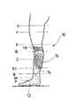
図1及び図2では、参照符号10は、従来の方法を用いて丸編機で作製された編物装具である本発明の装具を全体的に示す。この筒状の装具10は、足及び脚の一部を包む部分12と、足首を包む遠位部分14と、脹脛を包む近位部分16とを含む。この全体は、装具が「膝までの」ソックス(又は「脹脛までのソックス」)である場合には、膝の下に位置する高さ位置まで延びる。後者の場合、装具は「リブ編みタイプ」の編成終端部分18で終端する。
1 and 2,
このソックス形状の構成は限定的ではなく、本発明は、圧迫太腿部分20まで延びる「太腿までの」ストッキングとして実施することもできる。本発明の装具は、タイツとして作製することもでき、かつ/又は足部分12がなくてもよい(「足のない」タイプのストッキング又はタイツ)。
The sock-shaped configuration is not limiting and the present invention can also be implemented as an “up to thigh” stocking that extends to the
上述の装具の種々の隣接部分は丸編機で連続的に編まれ、すなわち、この装具が別個のパーツを組み付けるいかなる作製工程も必要としないが、当然ながら、つま先が存在する場合には足部分12のつま先を縫う作業は別である。 The various adjacent parts of the brace described above are continuously knitted on a circular knitting machine, i.e. this brace does not require any production steps to assemble separate parts, but of course the foot part if a toe is present. The work of sewing twelve toes is different.
図2は、標準的な表記を用いる、導入部で明記した形態学的な体系(「Hohenstein」型のモデル脚)によって定義される下肢の種々の高さ:
B:足首、その最小外周の地点、
B1:アキレス腱が脹脛筋肉とつながる地点、
C:脹脛、その最大外周の地点、
D:脛骨粗面の真下(すなわち膝の真下)、
E:膝蓋骨の中心、及び膝裏の上方(すなわち膝窩の高さ位置)
F:太腿の中間、並びに
G:太腿の上部、
を示す。
FIG. 2 shows various heights of the lower limb as defined by the morphological system specified in the introduction (model legs of the “Hohenstein” type) using standard notation:
B: Ankle, the point of its minimum circumference,
B1: The point where the Achilles tendon is connected to the calf muscle,
C: calf, maximum outer circumference point,
D: directly below the rough tibial surface (ie directly below the knee),
E: The center of the patella and the upper back of the knee (ie, the height position of the popliteal)
F: middle of the thigh, and G: upper part of the thigh,
Indicates.
脹脛は、高さ位置B1とDとの間に含まれる肢節であり、足首は、高さ位置B1の下に位置する肢節である。 The calf is a limb included between the height positions B1 and D, and the ankle is a limb located below the height position B1.
(足首の最小外周の)高さBにおいて加えられる圧力は、選択された標準化クラス(I、II、III又はIV)に関して規定された圧力である。 The pressure applied at height B (at the minimum circumference of the ankle) is the pressure specified for the selected standardization class (I, II, III or IV).
圧力値は、例えば、上述の規格NF G 30−102のB部による動力計を用いて、その規格によって規定されるHohenstein型のモデル脚のような基準の型に装具を履かせた後で読み取ることができる。 The pressure value is read after putting the brace on a reference mold such as a Hohenstein-type model leg defined by the standard using, for example, a dynamometer according to part B of the standard NF G 30-102. be able to.
弾性圧迫遠位部分14によって足首のその最小外周の地点(高さ位置B)に加えられる圧力は、効果的な治療圧力でなければならない。患者の必要性に応じて以下の値:
足首の比較的軽い圧迫には、10mmHg〜20mmHg(13hPa〜27hPa)、
足首の中程度の圧迫には、20mmHg〜30mmHg(27hPa〜40hPa)、
を保つことができる。
The pressure applied by the elastic compression
For relatively light pressure on the ankle, 10 mmHg to 20 mmHg (13 hPa to 27 hPa),
For moderate compression of the ankle, 20 mmHg-30 mmHg (27 hPa-40 hPa),
Can keep.
これらの治療圧力をもたらす弾性圧迫遠位部分14は、弾性のよこ糸、すなわち概して被覆されたスパンデックス糸を組み込んだ幾分密な織り方の編物から、例えば:
よこ糸として、ポリアミド及び/又は綿で被覆された、スパンデックス、又はスパンデックスとエラストジエン(ゴム糸)(合成ゴムラテックス)との混合物等の糸、及び
編み糸(縫い糸)として、好ましくは(単位長さ当たりの重量が)よこ糸よりも軽い寸法の、同様にポリアミド及び/又は綿で被覆されたスパンデックス糸、
を用いることによって作製される。
The elastic compression
As the weft yarn, it is preferably (unit length) as yarn such as spandex or a mixture of spandex and elastogen (rubber yarn) (synthetic rubber latex) coated with polyamide and / or cotton, and knitting yarn (sewing yarn). Spandex yarns that are lighter in weight than the weft yarns, also coated with polyamide and / or cotton,
It is produced by using.
本発明の特徴として、近位部分16は、筒状形状の副木部分(すなわち装具の最終的な状態で本質的に非弾性部分)であり、
垂直方向に:脹脛の範囲にわたって、すなわち高さ位置B1(アキレス腱と脹脛筋肉とつながる地点)と高さ位置D(膝下)との間、又は少なくともこの領域の大部分にわたって含まれる領域にわたって(足首(高さ位置Bの回りに延びる領域)は近位部分16によって覆われるこの領域に決して属しないことが観察されるはずである)、かつ
外周方向に:脹脛の全周にわたって、
延びる。
As a feature of the present invention, the
Vertically: over the range of the calf, ie between the height position B1 (the point where the Achilles tendon and calf muscle are connected) and the height position D (below the knee), or at least over a region contained over this region (ankle ( It should be observed that the region extending around height position B) never belongs to this region covered by the proximal portion 16), and in the circumferential direction: over the entire circumference of the calf
Extend.
この非弾性部分は、本明細書において以下で説明されるやり方であつらえられる、すなわち、患者の脹脛の形状及び寸法に正確に適合する外側構成を有する。その結果、装具を下肢に履くと、この部分が所望の副木効果を加え、すなわち、静止時には本質的に副木当ての力を加えないが、労作時には所望の程度の有効性で副木効果を与える剛性によって下肢に対抗する。 This inelastic portion is tailored in the manner described herein below, i.e., has an outer configuration that precisely matches the shape and dimensions of the patient's calf. As a result, when the brace is put on the lower limb, this part will add the desired splint effect, i.e. essentially no splinting force when stationary, but with the desired degree of effectiveness in the effort It resists the lower limbs by giving rigidity.
この副木近位部分16の剛性Rcに関して、(上述の欧州暫定規格XP ENV 12718:2001に従って)以下の値:
強い副木当てには、
Rc=15±2mmHg/cm(約20±2hPa/cm)、
中程度の副木当てには、
Rc=5mmHg/cm(約7hPa/cm)、
に保つことができる。
With regard to the stiffness R c of this splint
For strong splints,
R c = 15 ± 2 mmHg / cm (about 20 ± 2 hPa / cm),
For medium splint pads,
R c = 5 mmHg / cm (about 7 hPa / cm),
Can be kept in.
Rcのこれらの値は、高さC、すなわち脹脛の最大外周の地点で測定される。 These values of R c are measured at height C, the point of the maximum circumference of the calf.
一方で足首において圧迫遠位部分14の弾性に、また他方で脹脛において副木近位部分16の剛性に別個に作用することにより、幾つかの圧迫/副木当て効果、例えば:
足首における低圧迫/脹脛における強い副木、
足首における中程度の圧迫/脹脛における強い副木、
足首における低圧迫/脹脛における中程度の副木、又は
足首における中程度の圧迫/脹脛における中程度の副木、
を組み合わせることが可能である。
By acting separately on the one hand on the elasticity of the compression
A strong splint on the ankle, low pressure, and calf,
Medium splints at the ankles / strong splints at the calves,
Medium splint on low pressure compression / scalp at ankle, or medium splint on moderate compression / scalp at ankle,
Can be combined.
非常に有利には、遠位部分14及び近位部分16はともに、編機でひと続きに連続的に編まれ、これによって付加的なパーツを組み付けるいかなる作製工程も回避される。近位部分16はしたがって、弾性圧迫遠位部分14と同じタイプの糸、すなわち、
よこ糸としては、ポリアミド及び/又は綿で被覆されたスパンデックス糸、及び
編み糸としては、ポリアミド及び/又は綿で被覆された、より小さい寸法のスパンデックス糸
で編むことができる。
Highly advantageously, both the
The weft yarn can be knitted with a spandex yarn coated with polyamide and / or cotton, and the knitting yarn can be knitted with a smaller size spandex yarn coated with polyamide and / or cotton.
製品は、通常の技法に従ってサントーニ社製の編機のような従来の丸編機で編むことができる。 The product can be knitted on a conventional circular knitting machine, such as a Santoni knitting machine, according to conventional techniques.
本発明の特徴として、非弾性副木近位部分16は樹脂を加えることによって得られる。
As a feature of the present invention, the inelastic splint
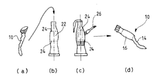
この作業は図3に示されるようになされる。 This operation is performed as shown in FIG.
まさに従来の方法で編まれた装具10は最初、標準的な製品、すなわち寸法に合わせて仕立てられていない製品の形態であり(工程a)、従来のEVC装具として、また更には、寸法表で選択される適した標準寸法の任意の布製品として準備されるに過ぎない。
Exactly knitted
この装具を次いで、患者の、脹脛の領域の形態に対応する型22に被せる(工程b)。この領域は、装具を履くと透明性によって見える印24等の印によって特に区切ることができる。
This brace is then placed over the
それに続く工程(工程c)は、例えばブラシ26を用いた塗布、制御された吹き付け又は浸漬によって、生体適合性樹脂を脹脛の領域に、すなわち印24間に加えることにある。
The subsequent step (step c) consists in applying a biocompatible resin to the calf region, i.e. between the
その目的で用いることができる樹脂の例は、例えば、REAL Composites社によって販売されている一液型アクリル樹脂であるPlastidurexという樹脂であり、この樹脂は例えば、紙及び布の剛性化、ランプのかさの形成等の装飾の分野において用いられる。 An example of a resin that can be used for this purpose is a plastic called Plasidurex, which is a one-part acrylic resin sold by REAL Composites, for example. Used in the field of decoration such as forming.
用いることができる別の樹脂はSILDOC RTV AD 35という樹脂であり、この樹脂は、同様にREAL Composites社によって販売されている二液型シリコーン樹脂であり、例えば物体の成形の分野において用いられる。 Another resin that can be used is SILDOC RTV AD 35, which is a two-part silicone resin also sold by REAL Composites, for example, in the field of object molding.
この樹脂は、編物が飽和するまで塗布され、蒸発によって乾燥される。 This resin is applied until the knitted fabric is saturated and dried by evaporation.
例示的な実施態様では、蒸発による硬化後に、本明細書において上記で定義したような脹脛の領域におけるソックスの全周にわたる塗布には、樹脂の初期重量に対して12gの樹脂がソックスに加えられたことが観察されている。得られた最終的な剛性は約15mmHg/cm(20mPa/cm)であった。 In an exemplary embodiment, after curing by evaporation, 12 g of resin is added to the sock, relative to the initial weight of the resin, for application over the entire circumference of the sock in the calf region as defined herein above. It has been observed. The final stiffness obtained was about 15 mmHg / cm (20 mPa / cm).
次いで、装具を型から取り外すことができる(工程d)。装具はこの場合、剛性になっているとともに患者の脹脛の曲線及び寸法に完全に適合する形状を呈する副木近位部分16と、弾性圧迫遠位部分14とを有する「寸法に合わせて仕立てられた」その明確な形状を有し、この結果、脹脛(副木近位部分16)における高い剛性と足首(弾性圧迫遠位部分14)における低い剛性とを関連付ける、下肢の治療的レベルの圧迫を提供する製品が得られる。
The brace can then be removed from the mold (step d). The brace in this case is tailored to size with a splint
Claims (8)
足首を覆い、脹脛が始まる手前、すなわちアキレス腱が脹脛筋肉とつながる地点まで延びるように構成されている弾性圧迫遠位部分(14)であって、
該遠位部分は、編み糸とよこ糸とを編むことによって作製され、該編み糸及び該よこ糸の寸法決め及び性質、並びに編物の構造は、該装具を下肢に履くと、所望の治療的レベルの圧力で下肢の圧迫をもたらすのに適した弾性復元力を周方向に加えるように選択される、弾性圧迫遠位部分(14)と、
前記圧迫遠位部分に続くとともに該圧迫遠位部分に隣接して、アキレス腱が脹脛筋肉とつながる地点の高さ位置(B1)と脛骨粗面の下に位置する高さ位置(D)との間に含まれる脹脛の領域をその外周にわたって包む副木近位部分(16)であって、
該副木近位部分は、前記弾性圧迫遠位部分と連続的に編まれる変形可能な筒状部分である、副木近位部分(16)と、
を含み、
該装具は、前記副木近位部分が、
本質的に非弾性であり、且つ
硬化生体適合性樹脂を組み込んでいることを特徴とする装具。 A medical lower limb compression / splinting brace in the form of socks, stockings or tights, the brace (10) comprising:
An elastic compression distal portion (14) configured to cover the ankle and extend to the point where the calf begins, i.e., to the point where the Achilles tendon connects with the calf muscle;
The distal portion is made by knitting a knitting yarn and a weft yarn, and the sizing and nature of the knitting yarn and the weft yarn, as well as the structure of the knitted fabric, provides the desired therapeutic level when the brace is worn on the lower limb. An elastic compression distal portion (14) selected to apply an elastic restoring force in the circumferential direction suitable to effect compression of the lower limb with pressure;
Between the height position (B1) where the Achilles tendon connects to the calf muscle and the height position (D) located below the rough surface of the tibia, following and adjacent to the compression distal portion A splint proximal portion (16) wrapping over the circumference of the calf region contained in
The proximal splint portion (16), which is a deformable tubular portion that is continuously knitted with the elastic compression distal portion;
Including
The brace has a proximal splint portion,
An appliance that is inherently inelastic and incorporates a cured biocompatible resin.
請求項1〜7のいずれか1項に記載の装具(10)を、生体適合性樹脂を有しない、未加工の初期状態で得る工程と、
前記装具を、前記患者の脹脛の形態を表す型に被せる工程と、
前記装具の、前記副木近位部分の領域に、硬化可能な生体適合性樹脂をその場で塗布する工程と、
前記装具を前記型上に維持した状態で前記樹脂を硬化させる工程と、
前記装具をその完成した状態で取り外す工程であって、前記装具は、その完成した状態では、前記樹脂の硬化後に剛性にされるとともに前記患者の脹脛の対応する寸法を保つ、副木近位部分(16)を有し、これによって該副木近位部分が脹脛の形状に完全に適合することが可能となる、取り外す工程と、
を含む方法。 A method of tailoring a medical leg compression / splinting brace to fit the patient's leg dimensions,
Obtaining the brace (10) according to any one of claims 1 to 7 in an unprocessed initial state without a biocompatible resin;
Placing the brace on a mold representing the shape of the patient's calf;
Applying in situ a curable biocompatible resin to a region of the proximal splint portion of the brace;
Curing the resin while maintaining the appliance on the mold;
Removing the brace in its finished state, wherein the brace is rigid in the finished state after the resin is cured and maintains the corresponding dimensions of the patient's calf (16), thereby allowing the splint proximal portion to fully conform to the calf shape;
Including methods.
Applications Claiming Priority (2)
| Application Number | Priority Date | Filing Date | Title |
|---|---|---|---|
| FR1160643 | 2011-11-22 | ||
| FR1160643A FR2982768B1 (en) | 2011-11-22 | 2011-11-22 | ORTHESE ADAPTED COMPRESSION / CONTENTION FOR REINFORCING THE MUSCULO-APONEVROTIC PUMP OF THE MOLLET |
Publications (2)
| Publication Number | Publication Date |
|---|---|
| JP2013106961A true JP2013106961A (en) | 2013-06-06 |
| JP2013106961A5 JP2013106961A5 (en) | 2014-01-09 |
Family
ID=47178525
Family Applications (1)
| Application Number | Title | Priority Date | Filing Date |
|---|---|---|---|
| JP2012256226A Pending JP2013106961A (en) | 2011-11-22 | 2012-11-22 | Adapted compression/splint orthosis for reinforcement of the calf musculoaponeurotic pump |
Country Status (11)
| Country | Link |
|---|---|
| US (2) | US9308116B2 (en) |
| EP (1) | EP2596777B1 (en) |
| JP (1) | JP2013106961A (en) |
| KR (1) | KR20130056841A (en) |
| CN (1) | CN103126807A (en) |
| BR (1) | BR102012029699A2 (en) |
| CA (1) | CA2797055C (en) |
| DK (1) | DK2596777T3 (en) |
| EA (1) | EA025768B1 (en) |
| ES (1) | ES2537237T3 (en) |
| FR (1) | FR2982768B1 (en) |
Families Citing this family (9)
| Publication number | Priority date | Publication date | Assignee | Title |
|---|---|---|---|---|
| JP5640232B2 (en) * | 2011-02-04 | 2014-12-17 | 岡本株式会社 | Breathable waterproof socks |
| WO2013063554A1 (en) * | 2011-10-28 | 2013-05-02 | Ing Source, Inc. | Compression foot garment, and therapeutic method for reducing heel pain |
| FR3040125B1 (en) * | 2015-08-20 | 2020-02-28 | Laboratoires Innothera | METHOD FOR DETERMINING A SIZE GRID |
| EP3323394B1 (en) * | 2016-11-21 | 2019-09-18 | 3M Innovative Properties Company | Compression sleeve |
| DE102017005187A1 (en) * | 2017-05-24 | 2018-11-29 | Bauerfeind Ag | compression stocking |
| CA3066871A1 (en) * | 2017-06-27 | 2019-01-03 | Peugas Carlos Maia, Lda | Sock for preventing ankle injury |
| EP3716926B1 (en) * | 2017-11-27 | 2023-10-04 | FXF GmbH | Method and stretching means for the manufacture of a medical and/or therapeutical stocking |
| DE102021115370A1 (en) * | 2021-06-14 | 2022-12-15 | Pedilay Care Gmbh | Bandage for enclosing a leg or arm portion of a living being |
| US11766074B1 (en) | 2022-06-03 | 2023-09-26 | Nina Louise Allen | Therapeutic sock |
Citations (9)
| Publication number | Priority date | Publication date | Assignee | Title |
|---|---|---|---|---|
| JPH03220334A (en) * | 1989-05-27 | 1991-09-27 | Jones Stroud & Co Ltd | Mixed fiber and its production |
| JPH0874148A (en) * | 1994-08-30 | 1996-03-19 | Nisshinbo Ind Inc | Feeder for elastic yarn of circular knitting machine |
| JPH08209402A (en) * | 1995-02-01 | 1996-08-13 | Unitika Ltd | Sock and its production |
| JP2001355101A (en) * | 2000-06-14 | 2001-12-26 | Naozumi Tsuda | Sprain preventive socks |
| FR2824471B1 (en) * | 2001-05-09 | 2003-06-27 | Alain Rodier | LOW THERAPEUTIC COMPRESSION / ELECTIVE CONTAINMENT |
| JP2004105323A (en) * | 2002-09-17 | 2004-04-08 | Mizuno Corp | Shoes and its manufacturing method |
| WO2006134875A1 (en) * | 2005-06-13 | 2006-12-21 | Kobayashi Pharmaceutical Co., Ltd. | Lower limb covering material |
| JP2008543404A (en) * | 2005-06-16 | 2008-12-04 | イノテラ トピック インターナショナル | Knitted compressible prosthesis for lower limbs to treat chronic venous insufficiency |
| EP1240880B1 (en) * | 2001-03-15 | 2011-10-05 | Robert Stolk | Therapeutic elastic envelope |
Family Cites Families (14)
| Publication number | Priority date | Publication date | Assignee | Title |
|---|---|---|---|---|
| US2901901A (en) * | 1956-07-16 | 1959-09-01 | Julius Kayser & Co | Stocking |
| US4008350A (en) * | 1972-08-31 | 1977-02-15 | Minnesota Mining And Manufacturing Company | Visco-elastic material comprising a polymeric foam impregnated with an acrylic resin |
| FR2606629B1 (en) * | 1986-11-19 | 1989-02-17 | Richard Freres Sa | METHOD FOR LOCAL LOCKING OF ELASTIC CONTAINMENT DEVICES |
| US5258036A (en) * | 1992-01-15 | 1993-11-02 | Carapace, Inc. | Body part mold and method of making |
| FR2755006B1 (en) | 1996-10-25 | 1998-12-18 | Couzan Serge | SOCKETS FOR THE PRACTICE OF SPORT |
| FR2813523B1 (en) * | 2000-09-04 | 2003-03-07 | Innothera Topic Int | COMPRESSIVE TUBULAR ORTHESIS FOR THE SUPPORT OF A LOWER LIMB AFTER VENOUS SURGERY, PARTICULARLY AFTER VEIN OR AMBULATORY PHLEBECTOMY |
| FR2874815B1 (en) * | 2004-09-09 | 2010-10-29 | Innothera Topic Int | COMPRESSIVE ORTHESIS TRICOTEE OF THE LOWER MEMBER FOR THE TREATMENT OF CHRONIC VENOUS INSUFFICIENCY |
| EP1656916A1 (en) * | 2004-11-10 | 2006-05-17 | Université Libre De Bruxelles | Tubular element for orthopedic cast |
| FR2882172B1 (en) | 2005-02-16 | 2007-11-02 | Innothera Soc Par Actions Simp | DEVICE FOR ASSISTING THE SELECTION OF A CONTAINING ORTHESIS BY SIMULATION OF ITS EFFECTS ON HEMODYNAMICS OF VENOUS RETURN |
| FR2885035B1 (en) * | 2005-05-02 | 2008-04-18 | Innothera Topic Internat Sa | COMPRESSIVE ORTHESIS OF THE LOWER LIMIT OF LOW TYPE TRICOTE ARTICLE, SOCK OR TIGHTS |
| FR2912644A1 (en) | 2007-02-19 | 2008-08-22 | Jean Marc Mollard | Restraining device for treating e.g. chronic venous disease, has film obtained by extrusion techniques with circular or plate patterns and made of polyethylene material, where thickness of film edges and homogeneity decrease pinch effect |
| DE102009043023A1 (en) * | 2009-08-24 | 2011-03-03 | Riesinger, geb. Dahlmann, Birgit | Wound care article with a plastically deformable or modelable active element |
| WO2011143489A2 (en) * | 2010-05-13 | 2011-11-17 | Vazales Brad E | Variable compression stockings |
| FR2967051B1 (en) | 2010-11-10 | 2012-11-30 | Innothera Topic Int | COMPRESSION / CONTENTION MEASUREMENT ORTHESIS, FOR THE STRENGTHENING OF THE MUSCULO-APONEVROTIC MOLLET PUMP. |
-
2011
- 2011-11-22 FR FR1160643A patent/FR2982768B1/en active Active
-
2012
- 2012-11-20 CA CA2797055A patent/CA2797055C/en active Active
- 2012-11-21 EA EA201201456A patent/EA025768B1/en not_active IP Right Cessation
- 2012-11-21 US US13/683,371 patent/US9308116B2/en active Active
- 2012-11-22 DK DK12193864.1T patent/DK2596777T3/en active
- 2012-11-22 ES ES12193864.1T patent/ES2537237T3/en active Active
- 2012-11-22 EP EP12193864.1A patent/EP2596777B1/en active Active
- 2012-11-22 JP JP2012256226A patent/JP2013106961A/en active Pending
- 2012-11-22 KR KR1020120133090A patent/KR20130056841A/en not_active Application Discontinuation
- 2012-11-22 CN CN2012105963957A patent/CN103126807A/en active Pending
- 2012-11-22 BR BRBR102012029699-3A patent/BR102012029699A2/en not_active Application Discontinuation
-
2016
- 2016-02-29 US US15/055,782 patent/US9597233B2/en active Active
Patent Citations (9)
| Publication number | Priority date | Publication date | Assignee | Title |
|---|---|---|---|---|
| JPH03220334A (en) * | 1989-05-27 | 1991-09-27 | Jones Stroud & Co Ltd | Mixed fiber and its production |
| JPH0874148A (en) * | 1994-08-30 | 1996-03-19 | Nisshinbo Ind Inc | Feeder for elastic yarn of circular knitting machine |
| JPH08209402A (en) * | 1995-02-01 | 1996-08-13 | Unitika Ltd | Sock and its production |
| JP2001355101A (en) * | 2000-06-14 | 2001-12-26 | Naozumi Tsuda | Sprain preventive socks |
| EP1240880B1 (en) * | 2001-03-15 | 2011-10-05 | Robert Stolk | Therapeutic elastic envelope |
| FR2824471B1 (en) * | 2001-05-09 | 2003-06-27 | Alain Rodier | LOW THERAPEUTIC COMPRESSION / ELECTIVE CONTAINMENT |
| JP2004105323A (en) * | 2002-09-17 | 2004-04-08 | Mizuno Corp | Shoes and its manufacturing method |
| WO2006134875A1 (en) * | 2005-06-13 | 2006-12-21 | Kobayashi Pharmaceutical Co., Ltd. | Lower limb covering material |
| JP2008543404A (en) * | 2005-06-16 | 2008-12-04 | イノテラ トピック インターナショナル | Knitted compressible prosthesis for lower limbs to treat chronic venous insufficiency |
Also Published As
| Publication number | Publication date |
|---|---|
| EP2596777B1 (en) | 2015-02-18 |
| CN103126807A (en) | 2013-06-05 |
| DK2596777T3 (en) | 2015-05-11 |
| ES2537237T3 (en) | 2015-06-03 |
| US20160175159A1 (en) | 2016-06-23 |
| FR2982768B1 (en) | 2013-11-22 |
| US9597233B2 (en) | 2017-03-21 |
| EP2596777A1 (en) | 2013-05-29 |
| KR20130056841A (en) | 2013-05-30 |
| BR102012029699A2 (en) | 2013-12-17 |
| EA025768B1 (en) | 2017-01-30 |
| EA201201456A1 (en) | 2013-05-30 |
| CA2797055A1 (en) | 2013-05-22 |
| US9308116B2 (en) | 2016-04-12 |
| US20130131572A1 (en) | 2013-05-23 |
| FR2982768A1 (en) | 2013-05-24 |
| CA2797055C (en) | 2019-12-10 |
Similar Documents
| Publication | Publication Date | Title |
|---|---|---|
| JP2013106961A (en) | Adapted compression/splint orthosis for reinforcement of the calf musculoaponeurotic pump | |
| US9180057B2 (en) | Made-to-measure orthosis for compression/containment, for reinforcing the musculo-aponeurotic pump of the calf | |
| KR101266547B1 (en) | A compressive restraining orthosis for the lower limb in the form of a knitted article of the stocking, sock, or tights type | |
| AU2009285830B2 (en) | Therapeutic compression garments | |
| US20080249454A1 (en) | Compression sock | |
| KR101488914B1 (en) | Elastic venous compression stocking that is easier to put on | |
| US20090240279A1 (en) | Knitted Compressive Orthosis of the Lower Limb for Treating Chronic Venous Insufficiency | |
| JP4105231B2 (en) | Elastic stocking type or elastic tights type compressible prosthesis | |
| CA3181653A1 (en) | Sock with functional biomechanical, circulatory and neurological efficacy | |
| RU2734815C2 (en) | Venous compression orthesis with variable pressure profile | |
| JP2018535729A (en) | Band to compress or support the joint | |
| AU2012258309A1 (en) | Adapted compression/splint orthosis for reinforcement of the calf musculo-aponeurotic pump |
Legal Events
| Date | Code | Title | Description |
|---|---|---|---|
| A521 | Written amendment |
Free format text: JAPANESE INTERMEDIATE CODE: A523 Effective date: 20131119 |
|
| A621 | Written request for application examination |
Free format text: JAPANESE INTERMEDIATE CODE: A621 Effective date: 20131119 |
|
| A131 | Notification of reasons for refusal |
Free format text: JAPANESE INTERMEDIATE CODE: A131 Effective date: 20150512 |
|
| A601 | Written request for extension of time |
Free format text: JAPANESE INTERMEDIATE CODE: A601 Effective date: 20150812 |
|
| A02 | Decision of refusal |
Free format text: JAPANESE INTERMEDIATE CODE: A02 Effective date: 20160126 |