JP2013103608A - Airbag device - Google Patents

Airbag device Download PDF

Info

Publication number
JP2013103608A
JP2013103608A JP2011248624A JP2011248624A JP2013103608A JP 2013103608 A JP2013103608 A JP 2013103608A JP 2011248624 A JP2011248624 A JP 2011248624A JP 2011248624 A JP2011248624 A JP 2011248624A JP 2013103608 A JP2013103608 A JP 2013103608A
Authority
JP
Japan
Prior art keywords
gas flow
gas
flow adjusting
adjusting member
inflator
Prior art date
Legal status (The legal status is an assumption and is not a legal conclusion. Google has not performed a legal analysis and makes no representation as to the accuracy of the status listed.)
Pending
Application number
JP2011248624A
Other languages
Japanese (ja)
Inventor
Hidetaka Azuma
英孝 東
Tadaaki Sekino
忠昭 関野
Tomoji Yamashita
智司 山下
Keisuke Moriya
圭介 森谷
Current Assignee (The listed assignees may be inaccurate. Google has not performed a legal analysis and makes no representation or warranty as to the accuracy of the list.)
Ashimori Industry Co Ltd
Original Assignee
Ashimori Industry Co Ltd
Priority date (The priority date is an assumption and is not a legal conclusion. Google has not performed a legal analysis and makes no representation as to the accuracy of the date listed.)
Filing date
Publication date
Application filed by Ashimori Industry Co Ltd filed Critical Ashimori Industry Co Ltd
Priority to JP2011248624A priority Critical patent/JP2013103608A/en
Publication of JP2013103608A publication Critical patent/JP2013103608A/en
Pending legal-status Critical Current

Links

Images

Abstract

PROBLEM TO BE SOLVED: To adjust the flow of gas ejected from an inflator, and improve the safety of an airbag device.SOLUTION: The inflator 2 ejects the gas from an ejecting unit 2A. The airbag inflates and expands by the gas supplied from the inflator 2. A gas flow adjusting member 31 surrounds the ejecting unit 2A and allows the gas ejected from the ejecting unit 2A to flow out from a flow out port 31C. The gas flow adjusting member 31 is deformed by gas pressure to form a gas discharging unit 31D. A deformation prevention member 60 has a deformation prevention function which prevents the gas flow adjusting member 31 from deforming and prevents formation of a discharging unit 31D. The deformation prevention member 60 loses the deformation prevention function at a predetermined temperature higher than the temperature in the inflation and expansion of the airbag.

Description

本発明は、ガスを噴出するインフレータを備えたエアバッグ装置に関する。   The present invention relates to an airbag apparatus including an inflator that ejects gas.

車両の緊急時や衝突時に乗員を保護するため、エアバッグ装置が使用されている。エアバッグ装置は、インフレータから噴出するガスによりエアバッグを膨張展開させる。乗員は、エアバッグにより受け止められる。その際、ガスガイドにより、インフレータから噴出するガスを一方向のみに噴出させるエアバッグモジュールが知られている(特許文献1参照)。   Airbag devices are used to protect passengers in the event of a vehicle emergency or collision. The airbag device inflates and deploys the airbag with the gas ejected from the inflator. The occupant is received by the airbag. At that time, an airbag module is known in which a gas ejected from an inflator is ejected in only one direction by a gas guide (see Patent Document 1).

ガスガイドは、ガス噴出し口と、補助ガス噴出し口を有する。補助ガス噴出し口は、樹脂又は布からなるガスガイドカバーで塞がれる。ガスは、ガス噴出し口から一方向に噴き出す。ガスの流れは、ガスガイドカバーにより一方向に調整される。これに対し、エアバッグモジュールが輸送中の火災等により高温にさらされると、ガスガイドカバーは、熱変形により補助ガス噴出し口を開く。その結果、インフレータがガスを発生しても、ガスは、ガスガイドから二方向に噴出する。ガスが一方向に噴出しないため、インフレータの急激な移動と大きな移動が抑制される。これにより、エアバッグモジュールの安全性を確保している。   The gas guide has a gas ejection port and an auxiliary gas ejection port. The auxiliary gas ejection port is closed with a gas guide cover made of resin or cloth. The gas is ejected in one direction from the gas ejection port. The gas flow is adjusted in one direction by a gas guide cover. On the other hand, when the airbag module is exposed to a high temperature due to a fire during transportation, the gas guide cover opens the auxiliary gas ejection port due to thermal deformation. As a result, even if the inflator generates gas, the gas is ejected from the gas guide in two directions. Since the gas is not ejected in one direction, rapid movement and large movement of the inflator are suppressed. Thereby, the safety | security of an airbag module is ensured.

ところが、従来のエアバッグモジュールでは、ガスの流れを確実に調整するために、補助ガス噴出し口からのガス漏れを防止する必要がある。そのため、樹脂製のガスガイドカバーにおいては、ガスガイドカバーを、ガスガイドに合わせて精度よく成形する必要がある。ガスガイドカバーを専用の型により成形するときには、ガスガイドカバーの製造コストが高くなる。   However, in the conventional airbag module, it is necessary to prevent gas leakage from the auxiliary gas ejection port in order to reliably adjust the gas flow. Therefore, in the resin gas guide cover, it is necessary to accurately mold the gas guide cover according to the gas guide. When the gas guide cover is formed by a dedicated mold, the manufacturing cost of the gas guide cover increases.

ガスガイドカバーが布からなるときには、熱に強い布や複数重ねた布をガスガイドに取り付ける必要がある。これにより、ガスガイドカバーが熱により破損するのを抑制する。また、補助ガス噴出し口からのガス漏れを防止する。しかしながら、熱に強い布は高いため、ガスガイドカバーのコストが増加する。布を複数重ねるときには、布の使用量が多くなるため、ガスガイドカバーの重量とコストが増加する傾向がある。布を複数重ねるため、ガスガイドカバーの外形寸法が大きくなる。ガスガイドカバーの形成にかかる時間と労力も増加する。従って、従来のエアバッグモジュールに関しては、ガスの流れの調整と安全性の向上を、より簡易かつ確実に実現するため、改良が求められている。   When the gas guide cover is made of cloth, it is necessary to attach a heat resistant cloth or a plurality of stacked cloths to the gas guide. This suppresses the gas guide cover from being damaged by heat. Further, gas leakage from the auxiliary gas outlet is prevented. However, since the heat-resistant cloth is expensive, the cost of the gas guide cover increases. When a plurality of cloths are stacked, since the amount of cloth used increases, the weight and cost of the gas guide cover tend to increase. Since a plurality of cloths are stacked, the outer dimensions of the gas guide cover are increased. The time and labor required to form the gas guide cover also increases. Therefore, the conventional airbag module is required to be improved in order to more easily and reliably realize the adjustment of the gas flow and the improvement of the safety.

特開2007−210370号公報JP 2007-210370 A

本発明は、前記従来の問題に鑑みなされたもので、その目的は、簡易かつ確実に、インフレータから噴出するガスの流れを調整するとともに、エアバッグ装置の安全性を向上させることである。   The present invention has been made in view of the above-described conventional problems, and an object thereof is to easily and reliably adjust the flow of gas ejected from the inflator and improve the safety of the airbag device.

本発明は、ガスを噴出部から噴出するインフレータと、インフレータから供給されるガスにより膨張展開するエアバッグと、を備えたエアバッグ装置であって、インフレータの噴出部を囲い、噴出部から噴出するガスを流出口から流出させるとともに、ガス圧により変形してガスの放出部を形成するガス流調整部材と、ガス流調整部材の変形を抑制して放出部の形成を防止する変形抑制機能を有し、エアバッグの膨張展開時における温度よりも高い所定温度で変形抑制機能を喪失する変形抑制部材と、を備えたエアバッグ装置である。   The present invention is an airbag device including an inflator that ejects gas from an ejection part, and an airbag that is inflated and deployed by gas supplied from the inflator, and surrounds the ejection part of the inflator and ejects from the ejection part A gas flow adjusting member that causes gas to flow out from the outlet and that deforms due to gas pressure to form a gas discharge portion, and a deformation suppression function that prevents deformation of the gas flow adjustment member and prevents formation of the discharge portion. And a deformation suppression member that loses the deformation suppression function at a predetermined temperature higher than the temperature at the time of inflation and deployment of the airbag.

本発明によれば、簡易かつ確実に、インフレータから噴出するガスの流れを調整できるとともに、エアバッグ装置の安全性を向上させることができる。   ADVANTAGE OF THE INVENTION According to this invention, while being able to adjust the flow of the gas ejected from an inflator simply and reliably, the safety | security of an airbag apparatus can be improved.

第1の実施形態のエアバッグ装置を示す図である。It is a figure which shows the airbag apparatus of 1st Embodiment. 第1の実施形態のエアバッグ装置の正面図である。It is a front view of the airbag apparatus of 1st Embodiment. エアバッグに取り付けるインフレータを示す図である。It is a figure which shows the inflator attached to an airbag. インフレータを示す図である。It is a figure which shows an inflator. 第1の実施形態のガス流調整部材を示す図である。It is a figure which shows the gas flow adjustment member of 1st Embodiment. 第1の実施形態の変形抑制部材の形成手順を示す図である。It is a figure which shows the formation procedure of the deformation | transformation suppression member of 1st Embodiment. エアバッグにガスを供給するインフレータを示す図である。It is a figure which shows the inflator which supplies gas to an airbag. 変形前後のガス流調整部材を示す斜視図である。It is a perspective view which shows the gas flow adjustment member before and behind a deformation | transformation. 第2の実施形態のガス流調整部材を示す図である。It is a figure which shows the gas flow adjustment member of 2nd Embodiment. エアバッグに取り付けるインフレータを示す図である。It is a figure which shows the inflator attached to an airbag. ガス流調整部材の変形について説明するための斜視図である。It is a perspective view for demonstrating a deformation | transformation of a gas flow adjustment member. 第3の実施形態のガス流調整部材を示す図である。It is a figure which shows the gas flow adjustment member of 3rd Embodiment. インフレータを示す図である。It is a figure which shows an inflator. エアバッグに取り付けるインフレータを示す図である。It is a figure which shows the inflator attached to an airbag. ガス流調整部材の変形について説明するための斜視図である。It is a perspective view for demonstrating a deformation | transformation of a gas flow adjustment member. 第4の実施形態のガス流調整部材を示す図である。It is a figure which shows the gas flow adjustment member of 4th Embodiment. エアバッグに取り付けるインフレータを示す図である。It is a figure which shows the inflator attached to an airbag. 第5の実施形態のガス流調整部材を示す図である。It is a figure which shows the gas flow adjustment member of 5th Embodiment. エアバッグに取り付けるインフレータを示す図である。It is a figure which shows the inflator attached to an airbag. 第6の実施形態のガス流調整部材を示す図である。It is a figure which shows the gas flow adjustment member of 6th Embodiment. エアバッグに取り付けるインフレータを示す図である。It is a figure which shows the inflator attached to an airbag. 第7の実施形態のガス流調整部材を示す図である。It is a figure which shows the gas flow adjustment member of 7th Embodiment. エアバッグに取り付けるインフレータを示す図である。It is a figure which shows the inflator attached to an airbag. 第8の実施形態のガス流調整部材を示す図である。It is a figure which shows the gas flow adjustment member of 8th Embodiment. 第8の実施形態の変形抑制部材の形成手順を示す図である。It is a figure which shows the formation procedure of the deformation | transformation suppression member of 8th Embodiment. エアバッグに取り付けるインフレータを示す図である。It is a figure which shows the inflator attached to an airbag. 第9の実施形態のガス流調整部材を示す図である。It is a figure which shows the gas flow adjustment member of 9th Embodiment. 第9の実施形態の変形抑制部材の形成手順を示す図である。It is a figure which shows the formation procedure of the deformation | transformation suppression member of 9th Embodiment. エアバッグに取り付けるインフレータを示す図である。It is a figure which shows the inflator attached to an airbag. 第10の実施形態のガス流調整部材を示す図である。It is a figure which shows the gas flow adjustment member of 10th Embodiment. エアバッグに取り付けるインフレータを示す図である。It is a figure which shows the inflator attached to an airbag. ガス流調整部材の変形について説明するための斜視図である。It is a perspective view for demonstrating a deformation | transformation of a gas flow adjustment member. 第11の実施形態のガス流調整部材を示す図である。It is a figure which shows the gas flow adjustment member of 11th Embodiment. エアバッグに取り付けるインフレータを示す図である。It is a figure which shows the inflator attached to an airbag. 第12の実施形態のガス流調整部材を示す斜視図である。It is a perspective view which shows the gas flow adjustment member of 12th Embodiment. エアバッグに取り付けるインフレータを示す図である。It is a figure which shows the inflator attached to an airbag. ガス流調整部材の変形について説明するための斜視図である。It is a perspective view for demonstrating a deformation | transformation of a gas flow adjustment member. 第13の実施形態のガス流調整部材を示す斜視図である。It is a perspective view which shows the gas flow adjustment member of 13th Embodiment. エアバッグに取り付けるインフレータを示す図である。It is a figure which shows the inflator attached to an airbag. ガス流調整部材の変形について説明するための斜視図である。It is a perspective view for demonstrating a deformation | transformation of a gas flow adjustment member. 第14の実施形態のガス流調整部材を示す図である。It is a figure which shows the gas flow adjustment member of 14th Embodiment. 第14の実施形態の変形抑制部材を示す斜視図である。It is a perspective view which shows the deformation | transformation suppression member of 14th Embodiment. エアバッグに取り付けるインフレータを示す図である。It is a figure which shows the inflator attached to an airbag. インフレータのガスの噴出について説明するための図である。It is a figure for demonstrating the ejection of the gas of an inflator. ガス流調整部材の変形について説明するための図である。It is a figure for demonstrating a deformation | transformation of a gas flow adjustment member. ガス流調整部材の変形について説明するための図である。It is a figure for demonstrating a deformation | transformation of a gas flow adjustment member. ガス流調整部材に形成するスリットの他の例を示す図である。It is a figure which shows the other example of the slit formed in a gas flow adjustment member.

以下、本発明のエアバッグ装置の一実施形態について図面を参照して説明する。
本実施形態のエアバッグ装置は、車両に搭載されて、エアバッグを膨張展開させる。エアバッグにより乗員を受け止めて保護する。以下では、カーテンエアバッグ装置(以下、単にエアバッグ装置という)を例に採り説明する。エアバッグ装置は、車両内の側壁に搭載される。エアバッグは、車両内でカーテン状に展開する。エアバッグは、側壁において乗員を保護する。
Hereinafter, an embodiment of an airbag device of the present invention will be described with reference to the drawings.
The airbag device of the present embodiment is mounted on a vehicle and inflates and deploys the airbag. Receiving and protecting passengers with airbags. Hereinafter, a curtain airbag device (hereinafter simply referred to as an airbag device) will be described as an example. The airbag device is mounted on a side wall in the vehicle. The airbag is deployed in a curtain shape in the vehicle. The airbag protects the occupant at the side wall.

(第1の実施形態)
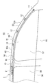
図1は、第1の実施形態のエアバッグ装置を示す図である。図1では、車両90に搭載したエアバッグ装置1を車室内から見て示している。また、車両90の側壁91とエアバッグ装置1を、車両90の後方側を省略して、かつ、車両90の幅方向から見て模式的に示している。エアバッグ装置1は、車両90の内面を透視して示している。
なお、ここでは、車両90における前方、後方、上方、下方を、単に前方、後方、上方、下方という。また、車両90における前後方向と上下方向を、単に前後方向と上下方向という。
(First embodiment)
FIG. 1 is a diagram illustrating an airbag device according to a first embodiment. In FIG. 1, the airbag apparatus 1 mounted in the vehicle 90 is shown as viewed from the passenger compartment. Further, the side wall 91 and the airbag device 1 of the vehicle 90 are schematically shown as viewed from the width direction of the vehicle 90 with the rear side of the vehicle 90 omitted. The airbag device 1 is shown through the inner surface of the vehicle 90.
Here, the front, rear, upper, and lower portions of the vehicle 90 are simply referred to as the front, rear, upper, and lower portions. Further, the front-rear direction and the vertical direction in the vehicle 90 are simply referred to as the front-rear direction and the vertical direction.

車両90は、図示のように、車室内の側壁91に、ルーフレール92、フロントピラー93、センターピラー94、及び、リアピラー(図示せず)を備えている。また、車両90は、側壁91に、前部ドア95、後部ドア96、及び、ドア95、96の窓97、98を備えている。側壁91には、フロントピラートリム93Aと、ヘッドライニング92Aの一部が取り付けられている。ヘッドライニング92Aは、ルーフ(図示せず)とルーフレール92を覆う。   As illustrated, the vehicle 90 includes a roof rail 92, a front pillar 93, a center pillar 94, and a rear pillar (not shown) on a side wall 91 in the passenger compartment. Further, the vehicle 90 includes a front door 95, a rear door 96, and windows 97 and 98 of the doors 95 and 96 on the side wall 91. A front pillar trim 93A and a part of the head lining 92A are attached to the side wall 91. The headlining 92A covers the roof (not shown) and the roof rail 92.

エアバッグ装置1は、膨張展開可能なエアバッグ(カーテンエアバッグ)10と、円柱状のインフレータ2を備えている。エアバッグ10は、車両90内に前後方向に沿って取り付けられる。エアバッグ10は、細長く折り畳まれた状態で側壁91の上部に配置される。また、エアバッグ10は、フロントピラートリム93Aとヘッドライニング92A内に配置される。エアバッグ10は、固定手段(図示せず)により、車体99に固定される。   The airbag device 1 includes an inflatable and deployable airbag (curtain airbag) 10 and a columnar inflator 2. The airbag 10 is attached in the vehicle 90 along the front-rear direction. The airbag 10 is arrange | positioned at the upper part of the side wall 91 in the state folded long and thin. The airbag 10 is disposed in the front pillar trim 93A and the headlining 92A. The airbag 10 is fixed to the vehicle body 99 by fixing means (not shown).

インフレータ2は、シリンダタイプのガス発生装置である。このエアバッグ装置1では、パイロ型のインフレータ2を使用する。インフレータ2は、火薬の燃焼によりガスを発生する。インフレータ2は、エアバッグ10内に挿入されて、エアバッグ10内でガスを発生する。インフレータ2は、センターピラー94の上方に配置される。インフレータ2は、固定手段(図示せず)により、ヘッドライニング92A内で車体99に固定される。   The inflator 2 is a cylinder type gas generator. In the airbag device 1, a pyro type inflator 2 is used. The inflator 2 generates gas by burning explosives. The inflator 2 is inserted into the airbag 10 and generates gas in the airbag 10. The inflator 2 is disposed above the center pillar 94. The inflator 2 is fixed to the vehicle body 99 in the headlining 92A by a fixing means (not shown).

車両緊急時や衝撃検知時に、インフレータ2は、エアバッグ10にガスを供給する。エアバッグ10は、インフレータ2から供給されるガスにより、側壁91の上部から下方に向かって膨張展開する。その際、エアバッグ10は、フロントピラートリム93Aとヘッドライニング92Aを押し開いて、車室内に展開する。エアバッグ10は、側壁91に沿ってカーテン状に膨張展開する。   The inflator 2 supplies gas to the airbag 10 at the time of vehicle emergency or impact detection. The airbag 10 is inflated and deployed downward from the upper part of the side wall 91 by the gas supplied from the inflator 2. At this time, the airbag 10 pushes open the front pillar trim 93A and the headlining 92A, and deploys in the vehicle interior. The airbag 10 is inflated and deployed in a curtain shape along the side wall 91.

図2は、エアバッグ装置1の正面図である。図2には、展開したエアバッグ10を示す。図2では、エアバッグ10内のガスの流れを矢印で示している。
エアバッグ10は、図示のように、前後方向に長い袋体である。エアバッグ10は、連結ベルト11と、複数の固定布12と、筒状のガス供給部13を有する。エアバッグ10の前方端は、連結ベルト11によりフロントピラー93に連結される。エアバッグ10は、固定布12により車体99に取り付けられる。連結ベルト11と固定布12は、ボルト等からなる固定手段(図示せず)により、フロントピラー93とルーフレール92に固定される。
FIG. 2 is a front view of the airbag device 1. FIG. 2 shows the deployed airbag 10. In FIG. 2, the gas flow in the airbag 10 is indicated by arrows.
As shown in the figure, the airbag 10 is a bag body that is long in the front-rear direction. The airbag 10 includes a connection belt 11, a plurality of fixed cloths 12, and a cylindrical gas supply unit 13. The front end of the airbag 10 is connected to the front pillar 93 by the connecting belt 11. The airbag 10 is attached to the vehicle body 99 by a fixed cloth 12. The connecting belt 11 and the fixing cloth 12 are fixed to the front pillar 93 and the roof rail 92 by fixing means (not shown) made of bolts or the like.

エアバッグ10は、乗員側の表基布(表パネル)14と、側壁91側の裏基布(裏パネル)15を有する。基布14、15は、同じ形状に形成された布(例えば、樹脂を被覆した布)からなる。重ねた基布14、15を、外縁接合部16で気密状に接合する。基布14、15は、外縁接合部16で、縫製により(又は、縫製と接着により)接合される。これにより、基布14、15の間に、膨張部20が形成される。膨張部20は、インフレータ2が発生するガスにより膨張する。   The airbag 10 has a front base fabric (front panel) 14 on the passenger side and a back base fabric (back panel) 15 on the side wall 91 side. The base cloths 14 and 15 are made of cloth (for example, cloth coated with resin) formed in the same shape. The overlapped base fabrics 14 and 15 are joined in an airtight manner at the outer edge joint portion 16. The base fabrics 14 and 15 are joined by sewing (or by sewing and adhesion) at the outer edge joint portion 16. Thereby, the expansion part 20 is formed between the base fabrics 14 and 15. The expansion part 20 is expanded by the gas generated by the inflator 2.

膨張部20は、前膨張部21、後膨張部22、及び、連結膨張部23からなる。前膨張部21は、エアバッグ10内の前方で膨張して、主に前席の乗員を受け止める。後膨張部22は、エアバッグ10内の後方で膨張して、主に後席の乗員を受け止める。連結膨張部23は、前膨張部21と後膨張部22を連結する。膨張部20は、複数の内部接合部17により区画される。内部接合部17は、外縁接合部16(膨張部20)内に位置する。基布14、15は、内部接合部17で、外縁接合部16と同様に接合される。内部接合部17により、複数の気室24〜27が膨張部20に形成される。   The expansion unit 20 includes a front expansion unit 21, a rear expansion unit 22, and a connection expansion unit 23. The front inflating portion 21 inflates in front of the airbag 10 and mainly receives the front seat occupant. The rear inflating portion 22 inflates behind the airbag 10 and mainly receives the occupant in the rear seat. The connection expansion part 23 connects the front expansion part 21 and the rear expansion part 22. The inflating part 20 is partitioned by a plurality of internal joint parts 17. The internal joint portion 17 is located in the outer edge joint portion 16 (inflatable portion 20). The base fabrics 14 and 15 are joined at the inner joint portion 17 in the same manner as the outer edge joint portion 16. A plurality of air chambers 24 to 27 are formed in the expansion portion 20 by the internal joint portion 17.

ガス供給部13は、エアバッグ10内にガスを供給するための開口部である。ガス供給部13は、エアバッグ10の前後方向の中間に形成され、前膨張部21の後方端に開口する。基布14、15は、ガス供給部13において、エアバッグ10の上縁部から斜め上方に突出する。ガス供給部13の縁部は、先端を除いて、外縁接合部16から連続して接合される。これにより、筒状のガス供給部13が形成される。ガス供給部13の両端部は開口している。ガス供給部13の一端部は、エアバッグ10の外部に開放されている。ガス供給部13の他端部は、膨張部20の内部に繋がる。   The gas supply unit 13 is an opening for supplying gas into the airbag 10. The gas supply unit 13 is formed in the middle of the airbag 10 in the front-rear direction and opens at the rear end of the front inflating unit 21. The base fabrics 14 and 15 protrude obliquely upward from the upper edge of the airbag 10 in the gas supply unit 13. The edge of the gas supply unit 13 is continuously joined from the outer edge joint 16 except for the tip. Thereby, the cylindrical gas supply part 13 is formed. Both ends of the gas supply unit 13 are open. One end of the gas supply unit 13 is open to the outside of the airbag 10. The other end of the gas supply unit 13 is connected to the inside of the expansion unit 20.

インフレータ2は、ガス供給部13に挿入され、エアバッグ10内に配置される。ガス供給部13は、バンド3によりインフレータ2に気密状に固定される。インフレータ2は、車体99に前後方向に沿って取り付けられる。ガス供給部13は、インフレータ2により曲げられる。インフレータ2は、ガス供給部13内でガスを発生する。ガス供給部13は、インフレータ2が発生するガスをエアバッグ10内へ供給する。ガスは、ガス供給部13からエアバッグ10の膨張部20へ供給される。ガスは、前膨張部21へ供給されるとともに、連結膨張部23を通って後膨張部22へ供給される。   The inflator 2 is inserted into the gas supply unit 13 and disposed in the airbag 10. The gas supply unit 13 is fixed to the inflator 2 in an airtight manner by the band 3. The inflator 2 is attached to the vehicle body 99 along the front-rear direction. The gas supply unit 13 is bent by the inflator 2. The inflator 2 generates gas in the gas supply unit 13. The gas supply unit 13 supplies the gas generated by the inflator 2 into the airbag 10. The gas is supplied from the gas supply unit 13 to the inflating unit 20 of the airbag 10. The gas is supplied to the front expansion part 21 and is supplied to the rear expansion part 22 through the connection expansion part 23.

次に、インフレータ2について、詳しく説明する。
図3は、エアバッグ10に取り付けるインフレータ2を示す図である。図3には、インフレータ2に取り付けられた部材も示している。図3Aは、図2に対応するインフレータ2の正面図である。図3Bは、図3Aの矢印X方向から見たインフレータ2の側面図である。図3Cは、インフレータ2の一部を図3BのY−Y線で切断して示す断面図である。
Next, the inflator 2 will be described in detail.
FIG. 3 is a view showing the inflator 2 attached to the airbag 10. FIG. 3 also shows a member attached to the inflator 2. FIG. 3A is a front view of the inflator 2 corresponding to FIG. 3B is a side view of the inflator 2 as seen from the direction of the arrow X in FIG. 3A. 3C is a cross-sectional view showing a part of the inflator 2 taken along the line YY of FIG. 3B.

エアバッグ装置1は、図示のように、ガス流調整部材30と、変形抑制部材60と、固定部材4を備えている。ガス流調整部材30は、インフレータ2に取り付けられる。変形抑制部材60は、ガス流調整部材30に取り付けられる。ガス流調整部材30は、インフレータ2が発生するガスの流れを調整する。変形抑制部材60は、ガス流調整部材30の変形を抑制する。固定部材4は、ガス流調整部材30をインフレータ2に固定する。その状態で、インフレータ2は、エアバッグ10のガス供給部13内に取り付けられる。インフレータ2は、ガス流調整部材30の内側でガスを発生する。   The airbag device 1 includes a gas flow adjusting member 30, a deformation suppressing member 60, and a fixing member 4 as illustrated. The gas flow adjusting member 30 is attached to the inflator 2. The deformation suppressing member 60 is attached to the gas flow adjusting member 30. The gas flow adjusting member 30 adjusts the flow of gas generated by the inflator 2. The deformation suppressing member 60 suppresses deformation of the gas flow adjusting member 30. The fixing member 4 fixes the gas flow adjusting member 30 to the inflator 2. In this state, the inflator 2 is attached in the gas supply unit 13 of the airbag 10. The inflator 2 generates gas inside the gas flow adjusting member 30.

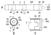
図4は、インフレータ2を示す図である。図4Aは、インフレータ2の正面図である。図4Bは、図4Aの矢印X方向から見たインフレータ2の側面図である。
インフレータ2は、図示のように、ガスの噴出部2Aを有する。噴出部2Aは、円柱状をなし、インフレータ2の長手方向の一端部に設けられている。複数のガスの噴出口(図示せず)が、噴出部2Aの外周に形成されている。インフレータ2は、ガスを噴出部2A(複数の噴出口)から放射状に噴出する。
FIG. 4 is a diagram showing the inflator 2. FIG. 4A is a front view of the inflator 2. 4B is a side view of the inflator 2 as seen from the direction of the arrow X in FIG. 4A.
The inflator 2 has a gas ejection part 2A as shown in the figure. The ejection portion 2 </ b> A has a cylindrical shape and is provided at one end portion in the longitudinal direction of the inflator 2. A plurality of gas ejection ports (not shown) are formed on the outer periphery of the ejection part 2A. The inflator 2 ejects gas radially from the ejection portion 2A (a plurality of ejection ports).

図5は、ガス流調整部材30を示す図である。図5Aは、形成前のガス流調整部材30の平面図である。図5Bは、形成後のガス流調整部材30の斜視図である。
ガス流調整部材30は、図示のように、矩形状に形成された変形可能なプレート30Aからなる。プレート30Aは、金属製の板状部材(例えば、鉄板)である。プレート30Aは、インフレータ2の外周に沿うように、筒状に曲げられる(図5Aの矢印R)。プレート30Aの両縁部30Bは、突き合わされる。ガス流調整部材30は、筒状に形成されたプレート30Aからなる。ガス流調整部材30の両端面は開口する。
FIG. 5 is a view showing the gas flow adjusting member 30. FIG. 5A is a plan view of the gas flow adjusting member 30 before formation. FIG. 5B is a perspective view of the gas flow adjusting member 30 after formation.
As shown in the figure, the gas flow adjusting member 30 includes a deformable plate 30A formed in a rectangular shape. The plate 30A is a metal plate member (for example, an iron plate). The plate 30A is bent into a tubular shape along the outer periphery of the inflator 2 (arrow R in FIG. 5A). Both edges 30B of the plate 30A are abutted. The gas flow adjusting member 30 includes a plate 30A formed in a cylindrical shape. Both end surfaces of the gas flow adjusting member 30 are opened.

インフレータ2(図3参照)は、筒状のガス流調整部材30内に挿入される。ガス流調整部材30は、インフレータ2の外周に装着される。ガス流調整部材30の一端部(先端部)は、噴出部2Aの周りに配置される。ガス流調整部材30は、2つの固定部材4によりインフレータ2に固定される。固定部材4は、環状のバンド4Aと、バンド4Aに取り付けられたボルト4Bを有する。バンド4Aは、ガス流調整部材30の外周に配置される。ガス流調整部材30をバンド4Aにより締め付けることで、ガス流調整部材30をインフレータ2に固定する。インフレータ2は、ボルト4Bにより、車両90に取り付けられる。   The inflator 2 (see FIG. 3) is inserted into a cylindrical gas flow adjusting member 30. The gas flow adjusting member 30 is attached to the outer periphery of the inflator 2. One end portion (tip portion) of the gas flow adjusting member 30 is disposed around the ejection portion 2A. The gas flow adjusting member 30 is fixed to the inflator 2 by the two fixing members 4. The fixing member 4 has an annular band 4A and a bolt 4B attached to the band 4A. The band 4 </ b> A is disposed on the outer periphery of the gas flow adjusting member 30. The gas flow adjusting member 30 is fixed to the inflator 2 by tightening the gas flow adjusting member 30 with the band 4A. The inflator 2 is attached to the vehicle 90 with a bolt 4B.

プレート30Aからなるガス流調整部材30は、インフレータ2に取り付けられる。ガス流調整部材30は、噴出部2Aを囲む。ガス流調整部材30の先端部は、噴出部2Aを覆う周壁である。噴出部2Aの全体が、ガス流調整部材30の内側に配置される。ガス流調整部材30は、ガスの流出口30Cからガスを流出する。流出口30Cは、ガス流調整部材30の一端面に位置する開口からなる。ガス流調整部材30の内部は、インフレータ2により塞がれる。ガス流調整部材30の先端部は、筒状の変形抑制部材60内に配置される。   The gas flow adjusting member 30 made of the plate 30 </ b> A is attached to the inflator 2. The gas flow adjusting member 30 surrounds the ejection part 2A. The distal end portion of the gas flow adjusting member 30 is a peripheral wall that covers the ejection portion 2A. The entire ejection portion 2 </ b> A is disposed inside the gas flow adjusting member 30. The gas flow adjusting member 30 flows out gas from the gas outlet 30C. The outlet 30 </ b> C includes an opening located on one end surface of the gas flow adjusting member 30. The inside of the gas flow adjusting member 30 is closed by the inflator 2. The distal end portion of the gas flow adjusting member 30 is disposed in the cylindrical deformation suppressing member 60.

図6は、変形抑制部材60の形成手順を示す図である。図6Aは、形成前の変形抑制部材60の平面図である。図6Bは、形成途中の変形抑制部材60の平面図である。図6Cは、形成後の変形抑制部材60の斜視図である。
変形抑制部材60は、図示のように、矩形状に形成されたシート又は布からなる。ここでは、変形抑制部材60は、エアバッグ10用の基布60Aからなる。基布60Aは、半分に折り畳まれる(図6Aの矢印S)。基布60Aの両縁部を重ねて縫製(図6Bの縫製部60B)する。これにより、変形抑制部材60を形成する(図6C参照)。
FIG. 6 is a diagram illustrating a procedure for forming the deformation suppressing member 60. FIG. 6A is a plan view of the deformation suppressing member 60 before formation. FIG. 6B is a plan view of the deformation suppressing member 60 being formed. FIG. 6C is a perspective view of the deformation suppressing member 60 after formation.
As shown in the figure, the deformation suppressing member 60 is made of a sheet or cloth formed in a rectangular shape. Here, the deformation suppressing member 60 is made of a base fabric 60 </ b> A for the airbag 10. The base fabric 60A is folded in half (arrow S in FIG. 6A). The both edge portions of the base fabric 60A are overlapped and sewn (the sewn portion 60B in FIG. 6B). Thereby, the deformation | transformation suppression member 60 is formed (refer FIG. 6C).

変形抑制部材60は、基布60Aにより形成された筒状部材からなる。変形抑制部材60(図3参照)は、ガス流調整部材30に密着するように、ガス流調整部材30に取り付けられる。変形抑制部材60は、ガス流調整部材30の外周に装着される。また、変形抑制部材60は、ガス流調整部材30の先端部を含む所定部分に取り付けられる。変形抑制部材60は、ガス流調整部材30の噴出部2Aを囲む部分を覆う。ガス流調整部材30の流出口30Cは、変形抑制部材60の開口部60Cに配置される。ガスは、ガス流調整部材30の流出口30Cを通って流出する。インフレータ2は、ガス流調整部材30を介してエアバッグ10にガスを供給する。   The deformation suppressing member 60 is formed of a cylindrical member formed by the base cloth 60A. The deformation suppressing member 60 (see FIG. 3) is attached to the gas flow adjusting member 30 so as to be in close contact with the gas flow adjusting member 30. The deformation suppressing member 60 is attached to the outer periphery of the gas flow adjusting member 30. Further, the deformation suppressing member 60 is attached to a predetermined portion including the distal end portion of the gas flow adjusting member 30. The deformation suppressing member 60 covers a portion surrounding the ejection part 2 </ b> A of the gas flow adjusting member 30. The outlet 30 </ b> C of the gas flow adjusting member 30 is disposed in the opening 60 </ b> C of the deformation suppressing member 60. The gas flows out through the outlet 30C of the gas flow adjusting member 30. The inflator 2 supplies gas to the airbag 10 via the gas flow adjusting member 30.

図7は、エアバッグ10にガスを供給するインフレータ2を示す図である。図7Aは、図3Cに対応する断面図である。図7Bは、インフレータ2の斜視図である。
上記したように、インフレータ2は、噴出部2Aからガスを放射状に噴出する。ガスは、図示のように、ガス流調整部材30の内周面に当たる。ガス流調整部材30は、噴出部2Aから噴出するガスを受ける。ガス流調整部材30により、ガスがエアバッグ10に直接当たるのを防止する。エアバッグ10は、ガス流調整部材30によりガスから保護される。ガス流調整部材30は、噴出部2Aとエアバッグ10の接触を防止して、エアバッグ10を保護する。ガス流調整部材30により、エアバッグ10の破損が防止される。
FIG. 7 is a diagram illustrating the inflator 2 that supplies gas to the airbag 10. FIG. 7A is a cross-sectional view corresponding to FIG. 3C. FIG. 7B is a perspective view of the inflator 2.
As described above, the inflator 2 ejects gas radially from the ejection portion 2A. As shown in the figure, the gas hits the inner peripheral surface of the gas flow adjusting member 30. The gas flow adjusting member 30 receives gas ejected from the ejection part 2A. The gas flow adjusting member 30 prevents the gas from directly hitting the airbag 10. The airbag 10 is protected from gas by the gas flow adjusting member 30. The gas flow adjusting member 30 protects the airbag 10 by preventing contact between the ejection portion 2 </ b> A and the airbag 10. The gas flow adjusting member 30 prevents the airbag 10 from being damaged.

ガスがガス流調整部材30に当たることで、ガスの流れる方向が変更される。ガス流調整部材30は、ガスを流出口30Cから所定方向(図7の矢印F方向)に流出させる。ガスは、流出口30Cのみから流出する。ガスの流れは、ガス流調整部材30により所定方向に調整される。ガス流調整部材30は、ガスの流れを一方向に調整する。ガスは、流出口30Cから一方向(ここでは、インフレータ2の長手方向)に流出して、エアバッグ10に供給される。エアバッグ10は、ガス流調整部材30により調整されたガスにより膨張展開する。   When the gas strikes the gas flow adjusting member 30, the direction in which the gas flows is changed. The gas flow adjusting member 30 causes the gas to flow out from the outlet 30C in a predetermined direction (the direction of arrow F in FIG. 7). The gas flows out only from the outlet 30C. The gas flow is adjusted in a predetermined direction by the gas flow adjusting member 30. The gas flow adjusting member 30 adjusts the gas flow in one direction. The gas flows out from the outlet 30C in one direction (here, the longitudinal direction of the inflator 2) and is supplied to the airbag 10. The airbag 10 is inflated and deployed by the gas adjusted by the gas flow adjusting member 30.

ガス流調整部材30は、噴出部2Aから噴出するガスの圧力(ガス圧)により広がるように変形する。ガス流調整部材30は、変形抑制部材60に押し付けられる。変形抑制部材60は、インフレータ2の作動時にガス流調整部材30の変形を抑制する。変形抑制部材60は、ガス流調整部材30を押さえて、ガス流調整部材30の形状を保持する。ガス流調整部材30は、変形抑制部材60により、ガス流を調整可能な状態に維持される。この通常時に対し、エアバッグ装置1が火災等により高温にさらされると、変形抑制部材60が破損する。例えば、変形抑制部材60は、溶けて変形する、又は、燃える。このような異常時にインフレータ2がガスを発生すると、ガス流調整部材30のガスを受ける部分が変形する。   The gas flow adjusting member 30 is deformed so as to expand due to the pressure (gas pressure) of the gas ejected from the ejection part 2A. The gas flow adjusting member 30 is pressed against the deformation suppressing member 60. The deformation suppressing member 60 suppresses deformation of the gas flow adjusting member 30 when the inflator 2 is operated. The deformation suppressing member 60 holds the shape of the gas flow adjusting member 30 while holding the gas flow adjusting member 30. The gas flow adjusting member 30 is maintained in a state in which the gas flow can be adjusted by the deformation suppressing member 60. If the airbag apparatus 1 is exposed to high temperature by a fire etc. with respect to this normal time, the deformation | transformation suppression member 60 will be damaged. For example, the deformation suppressing member 60 melts and deforms or burns. When the inflator 2 generates gas during such an abnormality, the portion of the gas flow adjusting member 30 that receives the gas is deformed.

図8は、変形前後のガス流調整部材30を示す斜視図である。図8には、変形抑制部材60が燃えてなくなったときのガス流調整部材30を示している。図8Aに、変形前のガス流調整部材30を示す。図8Bに、変形後のガス流調整部材30を示す。
ガス流調整部材30は、図示のように、ガス圧により変形する。ガス流調整部材30の両縁部30Bが外側へ向かって開くように変形する。これにより、ガス流調整部材30にガスの放出部30Dが形成される。放出部30Dは、ガス流調整部材30からガスを放出するための開放部である。ガス流調整部材30の変形により、放出部30Dが開放する。その際、ガス流調整部材30は、ガス圧により、噴出部2Aのガスの噴出方向の一部を開放して、ガスの放出部30Dを形成する。放出部30Dは、ガス流調整部材30の開放された部分からなる。
FIG. 8 is a perspective view showing the gas flow adjusting member 30 before and after deformation. FIG. 8 shows the gas flow adjusting member 30 when the deformation suppressing member 60 stops burning. FIG. 8A shows the gas flow adjusting member 30 before deformation. FIG. 8B shows the gas flow adjusting member 30 after deformation.
As shown in the figure, the gas flow adjusting member 30 is deformed by the gas pressure. The two edge portions 30B of the gas flow adjusting member 30 are deformed so as to open outward. Thereby, the gas discharge part 30 </ b> D is formed in the gas flow adjusting member 30. The discharge part 30 </ b> D is an open part for releasing gas from the gas flow adjusting member 30. Due to the deformation of the gas flow adjusting member 30, the discharge part 30D is opened. At that time, the gas flow adjusting member 30 opens a part of the gas ejection direction of the ejection part 2A by the gas pressure to form a gas ejection part 30D. The discharge part 30 </ b> D is composed of an open part of the gas flow adjusting member 30.

ガス流調整部材30の先端部が開くように変形することで、放出部30Dがガス流調整部材30の先端部に形成される。放出部30Dは、ガス流調整部材30の噴出部2Aを囲む部分に形成される。噴出部2Aから噴出するガスは、放出部30Dから、流出口30Cとは異なる方向に放出される。ガスは、流出口30Cと放出部30Dから噴出する。ガスは、ガス流調整部材30から多方向に噴出する。インフレータ2が誤作動したときに、ガスが一方向に噴出しないため、インフレータ2に一方向の推進力が働くのが防止される。その結果、インフレータ2が発射されるのが防止される。インフレータ2の急激な移動と大きな移動も抑制される。従って、火災等の高温の状態でインフレータ2が誤ってガスを発生したとしても、インフレータ2による危険を回避できる。また、輸送中や保管時におけるエアバッグ装置1の安全性が高くなる。   The discharge part 30 </ b> D is formed at the tip of the gas flow adjusting member 30 by being deformed so that the tip of the gas flow adjusting member 30 is opened. The discharge part 30 </ b> D is formed in a portion surrounding the ejection part 2 </ b> A of the gas flow adjusting member 30. The gas ejected from the ejection part 2A is ejected from the ejection part 30D in a direction different from the outlet 30C. The gas is ejected from the outlet 30C and the discharge part 30D. The gas is ejected from the gas flow adjusting member 30 in multiple directions. When the inflator 2 malfunctions, the gas is not ejected in one direction, so that the one-way propulsive force is prevented from acting on the inflator 2. As a result, the inflator 2 is prevented from being fired. A sudden movement and a large movement of the inflator 2 are also suppressed. Therefore, even if the inflator 2 accidentally generates gas in a high temperature state such as a fire, the danger caused by the inflator 2 can be avoided. Further, the safety of the airbag device 1 during transportation and storage is increased.

上記したように、変形抑制部材60は、ガス流調整部材30の変形抑制機能を有する。変形抑制機能は、ガス圧によるガス流調整部材30の変形を抑制して、放出部30Dの形成を防止する機能である。エアバッグ10の膨張展開時には、変形抑制部材60の変形抑制機能は維持される。即ち、エアバッグ10の膨張展開が開始するときからエアバッグ10の膨張展開が完了した後まで、変形抑制部材60は、変形抑制機能を発揮する。エアバッグ10の膨張展開時は、エアバッグ10にガスを供給するためにインフレータ2が作動するインフレータ2の作動時(通常作動時)である。インフレータ2の熱やガスの熱により変形抑制部材60が加熱されるため、変形抑制部材60の温度が上昇する。   As described above, the deformation suppressing member 60 has a deformation suppressing function of the gas flow adjusting member 30. The deformation suppressing function is a function of suppressing the deformation of the gas flow adjusting member 30 due to the gas pressure and preventing the formation of the discharge portion 30D. When the airbag 10 is inflated and deployed, the deformation suppressing function of the deformation suppressing member 60 is maintained. That is, the deformation suppressing member 60 exhibits a deformation suppressing function from when the airbag 10 starts to be inflated and deployed until after the airbag 10 has been inflated and deployed. When the airbag 10 is inflated and deployed, the inflator 2 is operated (normal operation) when the inflator 2 is operated to supply gas to the airbag 10. Since the deformation suppressing member 60 is heated by the heat of the inflator 2 and the heat of the gas, the temperature of the deformation suppressing member 60 rises.

変形抑制部材60は、エアバッグ10の膨張展開時における温度よりも高い所定温度で変形抑制機能を喪失する。エアバッグ10の膨張展開時における温度とは、エアバッグ10の膨張展開時に上昇する変形抑制部材60の温度の最高温度である。インフレータ2は、外部から加熱されたときに、温度の上昇によってガスを噴出することがある。上記した所定温度は、加熱によりガスを噴出するときのインフレータ2の温度よりも低い温度である。具体的には、変形抑制部材60は、エアバッグ10の膨張展開時における温度よりも高い温度の熱をエアバッグ装置1の外部から受けたときに破損する。これにより、変形抑制部材60は、変形抑制機能を喪失する。例えば、火災時には、変形抑制部材60は、火災による熱で破損する。変形抑制部材60が変形抑制機能を喪失した後は、ガス流調整部材30の変形が許容される。インフレータ2がガスを噴出したときに、ガス流調整部材30は、上記のように変形して、ガスの放出部30Dを形成する。   The deformation suppressing member 60 loses its deformation suppressing function at a predetermined temperature higher than the temperature when the airbag 10 is inflated and deployed. The temperature when the airbag 10 is inflated and deployed is the maximum temperature of the deformation suppressing member 60 that rises when the airbag 10 is inflated and deployed. When the inflator 2 is heated from the outside, gas may be ejected due to a rise in temperature. The above-mentioned predetermined temperature is a temperature lower than the temperature of the inflator 2 when gas is ejected by heating. Specifically, the deformation suppressing member 60 is damaged when receiving heat from the outside of the airbag apparatus 1 at a temperature higher than the temperature when the airbag 10 is inflated and deployed. Thereby, the deformation | transformation suppression member 60 loses a deformation | transformation suppression function. For example, at the time of a fire, the deformation suppressing member 60 is damaged by heat from the fire. After the deformation suppressing member 60 loses the deformation suppressing function, the gas flow adjusting member 30 is allowed to deform. When the inflator 2 ejects gas, the gas flow adjusting member 30 is deformed as described above to form a gas discharge portion 30D.

以上説明したように、ガス流調整部材30と変形抑制部材60により、簡易かつ確実に、インフレータ2から噴出するガスの流れを調整できる。また、火災等の高温時におけるエアバッグ装置1の安全性を、簡易かつ確実に向上させることができる。ガス流調整部材30と変形抑制部材60は、比較的簡単に低コストで形成できる。ここでは、以上の効果を、特性(例えば、融点と強度)が異なるガス流調整部材30と変形抑制部材60により実現している。エアバッグ装置1の外部から熱を受けたときに、変形抑制部材60は、変形抑制機能を喪失する。   As described above, the gas flow adjusting member 30 and the deformation suppressing member 60 can easily and reliably adjust the flow of gas ejected from the inflator 2. Moreover, the safety | security of the airbag apparatus 1 at the time of high temperature, such as a fire, can be improved simply and reliably. The gas flow adjusting member 30 and the deformation suppressing member 60 can be formed relatively easily and at low cost. Here, the above effects are realized by the gas flow adjusting member 30 and the deformation suppressing member 60 having different characteristics (for example, melting point and strength). When receiving heat from the outside of the airbag device 1, the deformation suppressing member 60 loses its deformation suppressing function.

筒状の変形抑制部材60により、ガス流調整部材30の外側への変形を確実に抑制できる。プレート30Aによりガス流調整部材30を形成するため、ガス流調整部材30を容易に形成できる。プレート30Aの変形により、放出部30Dがガス流調整部材30に確実に形成される。基布60Aからなる変形抑制部材60は、耐熱性を有するとともに、高温の熱により確実に破損する。変形抑制部材60を、ガス流調整部材30の噴出部2Aを囲む部分に対応する大きさに形成することで、変形抑制部材60を小さくできる。   The tubular deformation suppressing member 60 can reliably suppress the deformation of the gas flow adjusting member 30 to the outside. Since the gas flow adjusting member 30 is formed by the plate 30A, the gas flow adjusting member 30 can be easily formed. Due to the deformation of the plate 30 </ b> A, the discharge part 30 </ b> D is reliably formed in the gas flow adjusting member 30. The deformation suppressing member 60 made of the base fabric 60A has heat resistance and is reliably damaged by high-temperature heat. By forming the deformation suppressing member 60 in a size corresponding to the portion surrounding the ejection part 2A of the gas flow adjusting member 30, the deformation suppressing member 60 can be made small.

なお、変形抑制部材60は、放出部30Dの形成を防止できるようにガス流調整部材30の変形を抑制する。そのため、ガス流調整部材30は、ある程度変形してもよい。放出部30Dの形成に関係しない変形が、ガス流調整部材30に生じてもよい。火災以外でも、所定温度で、変形抑制部材60は、ガス流調整部材30の変形を抑制できなくなる。その際、変形抑制部材60は、熱により破損して変形抑制機能を喪失する。変形抑制部材60の破損は、例えば、溶け、変形、燃焼、劣化、又は、強度の低下である。変形抑制部材60が破損した状態で、ガス流調整部材30が変形することで、放出部30Dが形成される。   In addition, the deformation | transformation suppression member 60 suppresses a deformation | transformation of the gas flow adjustment member 30 so that formation of discharge | release part 30D can be prevented. Therefore, the gas flow adjusting member 30 may be deformed to some extent. Deformation not related to the formation of the discharge part 30 </ b> D may occur in the gas flow adjusting member 30. Even if it is not a fire, the deformation suppressing member 60 cannot suppress the deformation of the gas flow adjusting member 30 at a predetermined temperature. At that time, the deformation suppressing member 60 is damaged by heat and loses the deformation suppressing function. The breakage of the deformation suppressing member 60 is, for example, melting, deformation, combustion, deterioration, or strength reduction. In a state where the deformation suppressing member 60 is damaged, the gas flow adjusting member 30 is deformed to form the discharge portion 30D.

次に、ガス流調整部材と変形抑制部材の他の実施形態について説明する。以下説明するガス流調整部材と変形抑制部材は、基本的には、既に説明したガス流調整部材30と変形抑制部材60と同様に構成されている。また、各実施形態では、第1の実施形態の効果と同じ効果が得られる。そのため、以下では、既に説明した事項とは異なる事項を説明する。既に説明した事項と同じ事項は簡単に説明する。ガス流調整部材と変形抑制部材に関して、同じ構成には同じ名称を付す。   Next, other embodiments of the gas flow adjusting member and the deformation suppressing member will be described. The gas flow adjusting member and the deformation suppressing member described below are basically configured similarly to the gas flow adjusting member 30 and the deformation suppressing member 60 described above. Moreover, in each embodiment, the same effect as the effect of 1st Embodiment is acquired. Therefore, in the following, items different from those already described will be described. The same matters as already explained will be explained briefly. The same name is attached | subjected to the same structure regarding a gas flow adjustment member and a deformation | transformation suppression member.

(第2の実施形態)
図9は、第2の実施形態のガス流調整部材31を示す図である。
ガス流調整部材31は、図示のように、矩形状のプレート31Aからなる。プレート31Aを曲げて筒状に形成する。プレート31Aの両縁部31Bは、重ね合わせる。両縁部31Bの全体が所定幅で重なる。両縁部31Bを重ね合わせることを除いて、ガス流調整部材31は、第1の実施形態のガス流調整部材30と同様に構成されている。
(Second Embodiment)
FIG. 9 is a diagram illustrating a gas flow adjusting member 31 according to the second embodiment.
As shown in the figure, the gas flow adjusting member 31 includes a rectangular plate 31A. The plate 31A is bent to form a cylinder. Both edge portions 31B of the plate 31A are overlapped. The whole of both edge portions 31B overlap with a predetermined width. The gas flow adjusting member 31 is configured in the same manner as the gas flow adjusting member 30 of the first embodiment except that the both edge portions 31B are overlapped.

図10は、エアバッグ10に取り付けるインフレータ2を示す図である。図10Aは、図3Aに対応する正面図である。図10Bは、図3Bに対応する側面図である。図10Bでは、インフレータ2を図10Aの矢印X方向から見て示す。
筒状のガス流調整部材31は、図示のように、インフレータ2に取り付けられる。ガス流調整部材31の先端部は、インフレータ2の噴出部2Aを囲む。筒状の変形抑制部材60は、ガス流調整部材31の先端部に取り付けられる。
FIG. 10 is a view showing the inflator 2 attached to the airbag 10. FIG. 10A is a front view corresponding to FIG. 3A. FIG. 10B is a side view corresponding to FIG. 3B. 10B, the inflator 2 is shown as viewed from the direction of the arrow X in FIG. 10A.
The cylindrical gas flow adjusting member 31 is attached to the inflator 2 as illustrated. The distal end portion of the gas flow adjusting member 31 surrounds the ejection portion 2A of the inflator 2. The cylindrical deformation suppressing member 60 is attached to the distal end portion of the gas flow adjusting member 31.

図11は、ガス流調整部材31の変形について説明するための斜視図である。
ガス流調整部材31は、図11Aに示すように、インフレータ2の噴出部2Aから噴出するガスを受ける。ガスは、ガス流調整部材31の流出口31Cから所定方向Fに流出する。変形抑制部材60は、ガス流調整部材31の変形を抑制することで、放出部31D(図11D参照)の形成を防止する。変形抑制部材60は、図11Bに示すように、所定温度で変形抑制機能を喪失する。インフレータ2がガスを噴出すると、図11Cに示すように、ガス流調整部材31が、ガス圧により変形する。ガスの放出部31Dが、ガス流調整部材31に形成される。噴出部2Aのガスの噴出方向の一部が開放される。ガスは、流出口31Cと放出部31Dから噴出する。
FIG. 11 is a perspective view for explaining the deformation of the gas flow adjusting member 31.
As shown in FIG. 11A, the gas flow adjusting member 31 receives gas ejected from the ejection portion 2 </ b> A of the inflator 2. The gas flows out in the predetermined direction F from the outlet 31C of the gas flow adjusting member 31. The deformation suppressing member 60 prevents the discharge part 31D (see FIG. 11D) from being formed by suppressing the deformation of the gas flow adjusting member 31. As shown in FIG. 11B, the deformation suppressing member 60 loses the deformation suppressing function at a predetermined temperature. When the inflator 2 ejects gas, as shown in FIG. 11C, the gas flow adjusting member 31 is deformed by the gas pressure. A gas discharge part 31 </ b> D is formed in the gas flow adjusting member 31. Part of the gas ejection direction of the ejection part 2A is opened. The gas is ejected from the outlet 31C and the discharge part 31D.

このガス流調整部材31では、プレート31Aの両縁部31Bを重ね合わせたため、縁部31Bの間に隙間が生じるのを防止できる。その結果、エアバッグ10の膨張展開時に、ガス流調整部材31からガスが漏れるのを抑制できる。ガスは、流出口31Cから一方向に流出する。ガス流調整部材31により、インフレータ2から噴出するガスの流れを確実に調整できる。   In the gas flow adjusting member 31, since both the edge portions 31B of the plate 31A are overlapped, it is possible to prevent a gap from being generated between the edge portions 31B. As a result, gas can be prevented from leaking from the gas flow adjusting member 31 when the airbag 10 is inflated and deployed. The gas flows out in one direction from the outlet 31C. The gas flow adjusting member 31 can reliably adjust the flow of gas ejected from the inflator 2.

(第3の実施形態)
図12は、第3の実施形態のガス流調整部材32を示す図である。
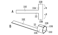
ガス流調整部材32は、図示のように、T字状に形成された板状部材からなる。ガス流調整部材32は、矩形状のプレート32A(本体部)と、インフレータ2に固定される固定部32Eを有する。固定部32Eは、プレート32Aと一体に形成された長板からなる。固定部32Eには、2つの挿入孔32Fが形成されている。プレート32Aを曲げて筒状に形成する(図12Aの矢印R)。プレート32Aの両縁部32Bは、重ね合わせる。ガス流調整部材32は、先端部に形成された筒状部32Gと、固定部32Eからなる。
(Third embodiment)
FIG. 12 is a diagram illustrating a gas flow adjusting member 32 according to the third embodiment.
As shown in the figure, the gas flow adjusting member 32 is composed of a plate-like member formed in a T shape. The gas flow adjusting member 32 has a rectangular plate 32 </ b> A (main body portion) and a fixing portion 32 </ b> E fixed to the inflator 2. The fixing portion 32E is a long plate formed integrally with the plate 32A. Two insertion holes 32F are formed in the fixing portion 32E. The plate 32A is bent to form a cylinder (arrow R in FIG. 12A). Both edge portions 32B of the plate 32A are overlapped. The gas flow adjusting member 32 includes a cylindrical portion 32G formed at the tip portion and a fixed portion 32E.

図13は、ガス流調整部材32を取り付けるインフレータ2を示す図である。図13Aは、インフレータ2の正面図である。図13Bは、図13Aの矢印X方向から見たインフレータ2の側面図である。
図示のように、インフレータ2には、2つの固定部材5が取り付けられている。固定部材5は、ボルトからなり、溶接によりインフレータ2に固定される。インフレータ2は、固定部材5により、車両90に取り付けられる。
FIG. 13 is a view showing the inflator 2 to which the gas flow adjusting member 32 is attached. FIG. 13A is a front view of the inflator 2. FIG. 13B is a side view of the inflator 2 as seen from the direction of the arrow X in FIG. 13A.
As shown in the figure, two fixing members 5 are attached to the inflator 2. The fixing member 5 is a bolt and is fixed to the inflator 2 by welding. The inflator 2 is attached to the vehicle 90 by the fixing member 5.

図14は、エアバッグ10に取り付けるインフレータ2を示す図である。図14では、図10と同様に、インフレータ2を側面図と正面図で示す。
ガス流調整部材32をインフレータ2に取り付けるときには、図示のように、インフレータ2の固定部材5を、固定部32Eの挿入孔32Fに挿入する。これにより、ガス流調整部材32がインフレータ2に固定される。ガス流調整部材32(筒状部32G)は、インフレータ2の先端部に取り付けられ、噴出部2Aの周りに配置される。インフレータ2の噴出部2Aは、筒状部32Gにより囲まれる。変形抑制部材60は、ガス流調整部材32の筒状部32Gに取り付けられる。
FIG. 14 is a view showing the inflator 2 attached to the airbag 10. In FIG. 14, the inflator 2 is shown in a side view and a front view as in FIG. 10.
When the gas flow adjusting member 32 is attached to the inflator 2, the fixing member 5 of the inflator 2 is inserted into the insertion hole 32F of the fixing portion 32E as illustrated. Thereby, the gas flow adjusting member 32 is fixed to the inflator 2. The gas flow adjusting member 32 (cylindrical portion 32G) is attached to the distal end portion of the inflator 2, and is disposed around the ejection portion 2A. The ejection part 2A of the inflator 2 is surrounded by a cylindrical part 32G. The deformation suppressing member 60 is attached to the cylindrical portion 32G of the gas flow adjusting member 32.

図15は、ガス流調整部材32の変形について説明するための斜視図である。
ガス流調整部材32は、図15Aに示すように、インフレータ2の噴出部2Aから噴出するガスを受ける。ガスは、ガス流調整部材32の流出口32Cから所定方向Fに流出する。変形抑制部材60は、ガス流調整部材32の変形を抑制することで、放出部32D(図15C参照)の形成を防止する。
FIG. 15 is a perspective view for explaining the deformation of the gas flow adjusting member 32.
As shown in FIG. 15A, the gas flow adjusting member 32 receives gas ejected from the ejection part 2 </ b> A of the inflator 2. The gas flows out in the predetermined direction F from the outlet 32C of the gas flow adjusting member 32. The deformation suppressing member 60 prevents the discharge part 32D (see FIG. 15C) from being formed by suppressing the deformation of the gas flow adjusting member 32.

変形抑制部材60は、図15Bに示すように、所定温度で変形抑制機能を喪失する。インフレータ2がガスを噴出すると、図15Cに示すように、ガス流調整部材32の筒状部32Gが、ガス圧により変形する。筒状部32Gの全体が外側へ向かって開くように変形する。筒状部32Gは広がる。これにより、ガスの放出部32Dが、ガス流調整部材32に形成される。噴出部2Aのガスの噴出方向の一部が開放される。放出部32Dは、固定部32E側の一部を除いた筒状部32Gに形成される。ガスは、流出口32Cと放出部32Dから噴出する。   As shown in FIG. 15B, the deformation suppressing member 60 loses the deformation suppressing function at a predetermined temperature. When the inflator 2 ejects gas, as shown in FIG. 15C, the cylindrical portion 32G of the gas flow adjusting member 32 is deformed by the gas pressure. It deform | transforms so that the whole cylindrical part 32G may open outward. The cylindrical part 32G spreads out. Thereby, the gas discharge part 32 </ b> D is formed in the gas flow adjusting member 32. Part of the gas ejection direction of the ejection part 2A is opened. Release part 32D is formed in cylindrical part 32G except a part by the side of fixed part 32E. The gas is ejected from the outlet 32C and the discharge part 32D.

このガス流調整部材32では、プレート32Aの両縁部32Bを重ね合わせたため、第2の実施形態のガス流調整部材31と同様の効果が得られる。また、固定部32Eをガス流調整部材32に設けたため、ガス流調整部材32をインフレータ2に固定し易くなる。ガス流調整部材32の固定作業を容易に行える。ガス流調整部材32の先端部のみを噴出部2Aを囲む筒状に形成したため、ガス流調整部材32を軽くできる。ガス流調整部材32はコンパクトになる。ガス流調整部材32のコストを削減することもできる。ガス流調整部材32の固定部32Eを、固定部材5によりインフレータ2に固定するため、ガス流調整部材32をインフレータ2に強固に固定できる。インフレータ2がガスを噴出するときに、ガス流調整部材32とインフレータ2の間にズレが生じるのを防止できる。ガス流調整部材32の位置の変化を抑制できる。   In this gas flow adjusting member 32, since both edge portions 32B of the plate 32A are overlapped, the same effect as the gas flow adjusting member 31 of the second embodiment can be obtained. Further, since the fixing portion 32E is provided on the gas flow adjusting member 32, the gas flow adjusting member 32 is easily fixed to the inflator 2. The fixing operation of the gas flow adjusting member 32 can be easily performed. Since only the distal end portion of the gas flow adjusting member 32 is formed in a cylindrical shape surrounding the ejection portion 2A, the gas flow adjusting member 32 can be lightened. The gas flow adjusting member 32 becomes compact. The cost of the gas flow adjusting member 32 can also be reduced. Since the fixing portion 32E of the gas flow adjusting member 32 is fixed to the inflator 2 by the fixing member 5, the gas flow adjusting member 32 can be firmly fixed to the inflator 2. When the inflator 2 ejects gas, it is possible to prevent a deviation from occurring between the gas flow adjusting member 32 and the inflator 2. A change in the position of the gas flow adjusting member 32 can be suppressed.

(第4の実施形態)
図16は、第4の実施形態のガス流調整部材33を示す図である。
ガス流調整部材33は、図示のように、プレート33Aと固定部33Eを有する。固定部33Eに挿入孔がないことを除いて、ガス流調整部材33は、第3の実施形態のガス流調整部材32と同様に構成されている。プレート33Aを曲げて筒状に形成する。プレート33Aの両縁部33Bは、重ね合わせる。ガス流調整部材33は、筒状部33Gと固定部33Eからなる。
(Fourth embodiment)
FIG. 16 is a diagram illustrating a gas flow adjusting member 33 according to the fourth embodiment.
As shown in the figure, the gas flow adjusting member 33 includes a plate 33A and a fixing portion 33E. The gas flow adjusting member 33 is configured in the same manner as the gas flow adjusting member 32 of the third embodiment except that the fixing portion 33E has no insertion hole. The plate 33A is bent to form a cylinder. Both edge portions 33B of the plate 33A are overlapped. The gas flow adjusting member 33 includes a cylindrical portion 33G and a fixed portion 33E.

図17は、エアバッグ10に取り付けるインフレータ2を示す図である。図17では、図10と同様に、インフレータ2を側面図と正面図で示す。
ガス流調整部材33(筒状部33G)は、図示のように、インフレータ2の先端部に取り付けられ、噴出部2Aの周りに配置される。ガス流調整部材33は、2つの固定部材4によりインフレータ2に固定される。固定部33Eが、バンド4Aによりインフレータ2に固定される。インフレータ2の噴出部2Aは、筒状部33Gにより囲まれる。変形抑制部材60は、ガス流調整部材33の筒状部33Gに取り付けられる。ガスは流出口33Cから流出する。このガス流調整部材33では、第3の実施形態のガス流調整部材32と同じ効果が得られる。
FIG. 17 is a view showing the inflator 2 attached to the airbag 10. In FIG. 17, as in FIG. 10, the inflator 2 is shown in a side view and a front view.
The gas flow adjusting member 33 (cylindrical portion 33G) is attached to the distal end portion of the inflator 2 and arranged around the ejection portion 2A as shown in the figure. The gas flow adjusting member 33 is fixed to the inflator 2 by the two fixing members 4. The fixing portion 33E is fixed to the inflator 2 by the band 4A. The ejection part 2A of the inflator 2 is surrounded by a cylindrical part 33G. The deformation suppressing member 60 is attached to the cylindrical portion 33G of the gas flow adjusting member 33. The gas flows out from the outlet 33C. In this gas flow adjusting member 33, the same effect as the gas flow adjusting member 32 of the third embodiment is obtained.

(第5の実施形態)
図18は、第5の実施形態のガス流調整部材34を示す図である。図19は、エアバッグ10に取り付けるインフレータ2を示す図である。
ガス流調整部材34は、図示のように、プレート34Aと固定部34Eを有する。固定部34Eには、2つの挿入孔34Fが形成されている。プレート34Aを曲げて筒状に形成する。プレート34Aの両縁部34Bは、突き合わせる。ガス流調整部材34は、筒状部34Gと固定部34Eからなる。ガスは流出口34Cから流出する。両縁部34Bを突き合わせることを除いて、ガス流調整部材34は、第3の実施形態のガス流調整部材32と同様に構成されている。
(Fifth embodiment)
FIG. 18 is a view showing a gas flow adjusting member 34 of the fifth embodiment. FIG. 19 is a view showing the inflator 2 attached to the airbag 10.
As shown in the figure, the gas flow adjusting member 34 has a plate 34A and a fixing portion 34E. Two insertion holes 34F are formed in the fixing portion 34E. The plate 34A is bent to form a cylinder. Both edges 34B of the plate 34A are abutted. The gas flow adjusting member 34 includes a cylindrical portion 34G and a fixed portion 34E. The gas flows out from the outlet 34C. The gas flow adjusting member 34 is configured in the same manner as the gas flow adjusting member 32 of the third embodiment except that both edge portions 34B are abutted.

(第6の実施形態)
図20は、第6の実施形態のガス流調整部材35を示す図である。図21は、エアバッグ10に取り付けるインフレータ2を示す図である。
ガス流調整部材35は、図示のように、プレート35Aと固定部35Eを有する。プレート35Aを曲げて筒状に形成する。プレート35Aの両縁部35Bは、突き合わせる。ガス流調整部材35は、筒状部35Gと固定部35Eからなる。ガスは流出口35Cから流出する。両縁部35Bを突き合わせることを除いて、ガス流調整部材35は、第4の実施形態のガス流調整部材33と同様に構成されている。
(Sixth embodiment)
FIG. 20 is a diagram illustrating a gas flow adjusting member 35 according to the sixth embodiment. FIG. 21 is a view showing the inflator 2 attached to the airbag 10.
As illustrated, the gas flow adjusting member 35 includes a plate 35A and a fixing portion 35E. The plate 35A is bent to form a cylinder. Both edge portions 35B of the plate 35A abut each other. The gas flow adjusting member 35 includes a cylindrical portion 35G and a fixed portion 35E. The gas flows out from the outlet 35C. The gas flow adjusting member 35 is configured in the same manner as the gas flow adjusting member 33 of the fourth embodiment except that both edge portions 35B are abutted.

(第7の実施形態)
図22は、第7の実施形態のガス流調整部材36を示す図である。
ガス流調整部材36は、図示のように、プレート36Aと固定部36Eと連結孔36Hを有する。ガス流調整部材36は、連結孔36Hを除き、第3の実施形態のガス流調整部材32と同様に構成されている。固定部36Eには、2つの挿入孔36Fが形成される。連結孔36Hは、プレート36Aの中央部に形成される。プレート36Aを曲げて筒状に形成する。プレート36Aの両縁部36Bは、重ね合わせる。ガス流調整部材36は、筒状部36Gと固定部36Eからなる。
(Seventh embodiment)
FIG. 22 is a diagram illustrating a gas flow adjusting member 36 according to the seventh embodiment.
As illustrated, the gas flow adjusting member 36 includes a plate 36A, a fixing portion 36E, and a connecting hole 36H. The gas flow adjusting member 36 is configured in the same manner as the gas flow adjusting member 32 of the third embodiment except for the connecting hole 36H. Two insertion holes 36F are formed in the fixing portion 36E. The connecting hole 36H is formed at the center of the plate 36A. The plate 36A is bent to form a cylinder. Both edges 36B of the plate 36A are overlapped. The gas flow adjusting member 36 includes a cylindrical portion 36G and a fixed portion 36E.

図23は、エアバッグ10に取り付けるインフレータ2を示す図である。図23Aは、インフレータ2の正面図である。図23Bは、図23Aの矢印X方向から見たインフレータ2の側面図である。図23Cは、図23AのZ−Z線で切断した断面図である。
ガス流調整部材36は、図示のように、インフレータ2に取り付けられる。変形抑制部材60は、ガス流調整部材36(筒状部36G)に取り付けられる。変形抑制部材60は、ガス流調整部材36の連結孔36Hに重なる連結孔60Dを有する。変形抑制部材60とガス流調整部材36は、連結部材6により連結される。連結部材6は、ボルト6Aとナット6Bからなる。ボルト6Aは、連結孔36H、60Dに挿入される。ナット6Bは、ボルト6Aに取り付けられる。連結部材6は、ボルト6Aとナット6Bにより、変形抑制部材60をガス流調整部材36に連結する。ガスは流出口36Cから流出する。
FIG. 23 is a view showing the inflator 2 attached to the airbag 10. FIG. 23A is a front view of the inflator 2. FIG. 23B is a side view of the inflator 2 as seen from the direction of the arrow X in FIG. 23A. 23C is a cross-sectional view taken along line ZZ in FIG. 23A.
The gas flow adjusting member 36 is attached to the inflator 2 as illustrated. The deformation suppressing member 60 is attached to the gas flow adjusting member 36 (tubular portion 36G). The deformation suppressing member 60 has a connection hole 60D that overlaps the connection hole 36H of the gas flow adjusting member 36. The deformation suppressing member 60 and the gas flow adjusting member 36 are connected by the connecting member 6. The connecting member 6 includes a bolt 6A and a nut 6B. The bolt 6A is inserted into the connection holes 36H and 60D. The nut 6B is attached to the bolt 6A. The connecting member 6 connects the deformation suppressing member 60 to the gas flow adjusting member 36 by a bolt 6A and a nut 6B. The gas flows out from the outlet 36C.

このガス流調整部材36では、第3の実施形態のガス流調整部材32と同じ効果が得られる。連結部材6により、変形抑制部材60をガス流調整部材36に連結するため、変形抑制部材60の位置の変化を抑制できる。インフレータ2がガスを噴出するときに、ガス流調整部材36と変形抑制部材60の間にズレが生じるのを防止できる。その結果、変形抑制部材60により、ガス流調整部材36の変形を確実に抑制できる。なお、リベットからなる連結部材6により、変形抑制部材60をガス流調整部材36に連結してもよい。   In this gas flow adjusting member 36, the same effect as the gas flow adjusting member 32 of the third embodiment is obtained. Since the deformation suppressing member 60 is connected to the gas flow adjusting member 36 by the connecting member 6, a change in the position of the deformation suppressing member 60 can be suppressed. When the inflator 2 ejects gas, it is possible to prevent a deviation from occurring between the gas flow adjusting member 36 and the deformation suppressing member 60. As a result, the deformation suppressing member 60 can reliably suppress the deformation of the gas flow adjusting member 36. Note that the deformation suppressing member 60 may be connected to the gas flow adjusting member 36 by a connecting member 6 made of rivets.

(第8の実施形態)
図24は、第8の実施形態のガス流調整部材37を示す図である。
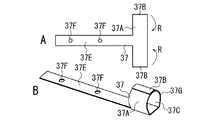
ガス流調整部材37は、第3の実施形態のガス流調整部材32と同様に構成されている。ガス流調整部材37は、図示のように、プレート37Aと、固定部37Eを有する。固定部37Eには、2つの挿入孔37Fが形成されている。プレート37Aを曲げて筒状に形成する。プレート37Aの両縁部37Bは、重ね合わせる。ガス流調整部材37は、筒状部37Gと固定部37Eからなる。
(Eighth embodiment)
FIG. 24 is a diagram illustrating a gas flow adjusting member 37 according to the eighth embodiment.
The gas flow adjusting member 37 is configured in the same manner as the gas flow adjusting member 32 of the third embodiment. As illustrated, the gas flow adjusting member 37 includes a plate 37A and a fixing portion 37E. Two insertion holes 37F are formed in the fixing portion 37E. The plate 37A is bent to form a cylinder. Both edge portions 37B of the plate 37A are overlapped. The gas flow adjusting member 37 includes a cylindrical portion 37G and a fixed portion 37E.

図25は、変形抑制部材61の形成手順を示す図である。図25Aは、形成前の変形抑制部材61の平面図である。図25Bは、形成途中の変形抑制部材61の平面図である。図25Cは、形成後の変形抑制部材61の斜視図である。
変形抑制部材61は、図示のように、T字状に形成された基布61Aからなる。基布61Aは、半分に折り畳まれる(図25Aの矢印H)。基布61Aの先端部を重ねて縫製(図25Bの縫製部61B)する。変形抑制部材61の先端部は、筒状に形成される(図25C参照)。変形抑制部材61は、筒状部61Eと固定部61Fからなる。固定部61Fには、2つの挿入孔61Gが形成されている。
FIG. 25 is a diagram illustrating a procedure for forming the deformation suppressing member 61. FIG. 25A is a plan view of the deformation suppressing member 61 before formation. FIG. 25B is a plan view of the deformation suppressing member 61 being formed. FIG. 25C is a perspective view of the deformation suppressing member 61 after formation.
As shown in the figure, the deformation suppressing member 61 is composed of a base cloth 61A formed in a T shape. The base fabric 61A is folded in half (arrow H in FIG. 25A). The front end portion of the base fabric 61A is overlapped and sewn (the sewn portion 61B in FIG. 25B). The distal end portion of the deformation suppressing member 61 is formed in a cylindrical shape (see FIG. 25C). The deformation suppressing member 61 includes a cylindrical portion 61E and a fixing portion 61F. Two insertion holes 61G are formed in the fixing portion 61F.

図26は、エアバッグ10に取り付けるインフレータ2を示す図である。図26では、図10と同様に、インフレータ2を側面図と正面図で示す。
ガス流調整部材37(筒状部37G)は、図示のように、インフレータ2の先端部に取り付けられる。その際、インフレータ2の固定部材5を、固定部37Eの挿入孔37Fに挿入する。変形抑制部材61は、基布61Aにより形成された筒状部材からなる。変形抑制部材61(筒状部61E)は、ガス流調整部材37の筒状部37Gに取り付けられる。インフレータ2の固定部材5を、固定部61Fの挿入孔61Gに挿入する。固定部材5により、ガス流調整部材37と変形抑制部材61をインフレータ2に固定する。ガスは流出口37Cから流出する。
FIG. 26 is a view showing the inflator 2 attached to the airbag 10. In FIG. 26, the inflator 2 is shown in a side view and a front view as in FIG.
The gas flow adjusting member 37 (cylindrical portion 37G) is attached to the tip of the inflator 2 as shown in the figure. At that time, the fixing member 5 of the inflator 2 is inserted into the insertion hole 37F of the fixing portion 37E. The deformation suppressing member 61 is formed of a cylindrical member formed by the base cloth 61A. The deformation suppressing member 61 (cylindrical portion 61E) is attached to the cylindrical portion 37G of the gas flow adjusting member 37. The fixing member 5 of the inflator 2 is inserted into the insertion hole 61G of the fixing portion 61F. The gas flow adjusting member 37 and the deformation suppressing member 61 are fixed to the inflator 2 by the fixing member 5. The gas flows out from the outlet 37C.

変形抑制部材61をインフレータ2に固定することで、変形抑制部材61の位置の変化を抑制できる。インフレータ2がガスを噴出するときに、ガス流調整部材37と変形抑制部材61の間にズレが生じるのを防止できる。その結果、変形抑制部材61により、ガス流調整部材37の変形を確実に抑制できる。   By fixing the deformation suppressing member 61 to the inflator 2, a change in the position of the deformation suppressing member 61 can be suppressed. When the inflator 2 ejects gas, it is possible to prevent a deviation from occurring between the gas flow adjusting member 37 and the deformation suppressing member 61. As a result, the deformation suppressing member 61 can reliably suppress the deformation of the gas flow adjusting member 37.

(第9の実施形態)
図27は、第9の実施形態のガス流調整部材38を示す図である。
ガス流調整部材38は、図示のように、プレート38Aと、固定部38Eと、2つのガスの流出孔38Iを有する。ガス流調整部材38は、流出孔38Iを除いて、第3の実施形態のガス流調整部材32と同様に構成されている。固定部38Eには、2つの挿入孔38Fが形成されている。プレート38Aを曲げて筒状に形成する。プレート38Aの両縁部38Bは、重ね合わせる。ガス流調整部材38は、筒状部38Gと固定部38Eからなる。流出孔38Iは、筒状部38Gの側部に形成される。
(Ninth embodiment)
FIG. 27 is a diagram illustrating a gas flow adjusting member 38 according to the ninth embodiment.
As illustrated, the gas flow adjusting member 38 includes a plate 38A, a fixing portion 38E, and two gas outflow holes 38I. The gas flow adjusting member 38 is configured in the same manner as the gas flow adjusting member 32 of the third embodiment except for the outflow hole 38I. Two insertion holes 38F are formed in the fixing portion 38E. The plate 38A is bent to form a cylinder. Both edge portions 38B of the plate 38A are overlapped. The gas flow adjusting member 38 includes a cylindrical portion 38G and a fixed portion 38E. The outflow hole 38I is formed in the side part of the cylindrical part 38G.

図28は、変形抑制部材62の形成手順を示す図である。図28Aは、形成前の変形抑制部材62の平面図である。図28Bは、形成途中の変形抑制部材62の平面図である。図28Cは、形成後の変形抑制部材62の斜視図である。
変形抑制部材62は、図示のように、矩形状に形成された基布62Aからなる。基布62Aには、2つの流出孔62Hが形成されている。変形抑制部材62は、流出孔62Hを除いて、第1の実施形態の変形抑制部材60と同様に構成されている。基布62Aを縫製(図28Bの縫製部62B)することで、筒状の変形抑制部材62を形成する。
FIG. 28 is a diagram illustrating a procedure for forming the deformation suppressing member 62. FIG. 28A is a plan view of the deformation suppressing member 62 before formation. FIG. 28B is a plan view of the deformation suppressing member 62 being formed. FIG. 28C is a perspective view of the deformation suppressing member 62 after formation.
As shown in the figure, the deformation suppressing member 62 is composed of a base fabric 62A formed in a rectangular shape. Two outflow holes 62H are formed in the base cloth 62A. The deformation suppressing member 62 is configured in the same manner as the deformation suppressing member 60 of the first embodiment except for the outflow hole 62H. The tubular deformation suppressing member 62 is formed by sewing the base cloth 62A (the sewing portion 62B in FIG. 28B).

図29は、エアバッグ10に取り付けるインフレータ2を示す図である。図29では、図10と同様に、インフレータ2を側面図と正面図で示す。
ガス流調整部材38(筒状部38G)は、図示のように、インフレータ2の先端部に取り付けられる。変形抑制部材62は、ガス流調整部材38の筒状部38Gに取り付けられる。変形抑制部材62の流出孔62Hの位置を、ガス流調整部材38の流出孔38Iの位置に合わせる。ガス流調整部材38は、流出口38Cと2つの流出孔38Iからガスを流出させる。ガスは、流出孔38I、62Hを通って流出する。従って、流出孔38Iは、ガス流調整部材38に設けられたガスの流出口である。ガスは、ガス流調整部材38から三方向に流出する。このように、ガス流調整部材38には、複数のガスの流出口を設けるようにしてもよい。
FIG. 29 is a view showing the inflator 2 attached to the airbag 10. 29, the inflator 2 is shown in a side view and a front view as in FIG.
The gas flow adjusting member 38 (cylindrical portion 38G) is attached to the distal end portion of the inflator 2 as illustrated. The deformation suppressing member 62 is attached to the cylindrical portion 38G of the gas flow adjusting member 38. The position of the outflow hole 62H of the deformation suppressing member 62 is matched with the position of the outflow hole 38I of the gas flow adjusting member 38. The gas flow adjusting member 38 causes the gas to flow out from the outflow port 38C and the two outflow holes 38I. The gas flows out through the outflow holes 38I and 62H. Accordingly, the outflow hole 38I is a gas outlet provided in the gas flow adjusting member 38. The gas flows out from the gas flow adjusting member 38 in three directions. Thus, the gas flow adjusting member 38 may be provided with a plurality of gas outlets.

(第10の実施形態)
図30は、第10の実施形態のガス流調整部材39を示す図である。
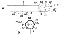
ガス流調整部材39は、図示のように、プレート39Aと固定部39Eを有する。また、ガス流調整部材39は、インフレータ2の噴出部2Aを囲む部分に複数のスリット39Jを有する。ガス流調整部材39は、スリット39Jを除いて、第5の実施形態のガス流調整部材34と同様に構成されている。固定部39Eには、2つの挿入孔39Fが形成されている。プレート39Aを曲げて筒状に形成する。プレート39Aの両縁部39Bは、突き合わせる。ガス流調整部材39は、筒状部39Gと固定部39Eからなる。複数のスリット39Jは、筒状部39Gに等間隔に形成されている。スリット39Jは、筒状部39Gの一端面(流出口39C側の端面)から他端面に向かって形成されている。
(Tenth embodiment)
FIG. 30 is a diagram illustrating a gas flow adjusting member 39 according to the tenth embodiment.
The gas flow adjusting member 39 has a plate 39A and a fixing portion 39E as shown in the figure. Further, the gas flow adjusting member 39 has a plurality of slits 39J in a portion surrounding the ejection part 2A of the inflator 2. The gas flow adjusting member 39 is configured in the same manner as the gas flow adjusting member 34 of the fifth embodiment except for the slit 39J. Two insertion holes 39F are formed in the fixing portion 39E. The plate 39A is bent to form a cylinder. Both edges 39B of the plate 39A are abutted. The gas flow adjusting member 39 includes a cylindrical portion 39G and a fixed portion 39E. The plurality of slits 39J are formed at equal intervals in the cylindrical portion 39G. The slit 39J is formed from one end surface (end surface on the outflow port 39C side) of the cylindrical portion 39G toward the other end surface.

図31は、エアバッグ10に取り付けるインフレータ2を示す図である。図31では、図10と同様に、インフレータ2を側面図と正面図で示す。
ガス流調整部材39(筒状部39G)は、図示のように、インフレータ2の先端部に取り付けられる。筒状部39Gは、インフレータ2の噴出部2Aを囲む。変形抑制部材60は、ガス流調整部材39の筒状部39Gに取り付けられる。
FIG. 31 is a view showing the inflator 2 attached to the airbag 10. In FIG. 31, as in FIG. 10, the inflator 2 is shown in a side view and a front view.
The gas flow adjusting member 39 (cylindrical portion 39G) is attached to the distal end portion of the inflator 2 as illustrated. The tubular portion 39G surrounds the ejection portion 2A of the inflator 2. The deformation suppressing member 60 is attached to the cylindrical portion 39G of the gas flow adjusting member 39.

図32は、ガス流調整部材39の変形について説明するための斜視図である。
ガス流調整部材39は、図32Aに示すように、インフレータ2の噴出部2Aから噴出するガスを受ける。ガスは、ガス流調整部材39の流出口39Cから所定方向Fに流出する。変形抑制部材60は、ガス流調整部材39の変形を抑制することで、放出部39D(図32C参照)の形成を防止する。
FIG. 32 is a perspective view for explaining the deformation of the gas flow adjusting member 39.
As shown in FIG. 32A, the gas flow adjusting member 39 receives gas ejected from the ejection part 2 </ b> A of the inflator 2. The gas flows out in the predetermined direction F from the outlet 39C of the gas flow adjusting member 39. The deformation suppressing member 60 prevents the discharge part 39D (see FIG. 32C) from being formed by suppressing the deformation of the gas flow adjusting member 39.

変形抑制部材60は、図32Bに示すように、所定温度で変形抑制機能を喪失する。インフレータ2がガスを噴出すると、図32Cに示すように、ガス流調整部材39の筒状部39Gが、ガス圧により変形する。筒状部39Gの全体が外側へ向かって開くように変形する。筒状部39Gは広がる。同時に、筒状部39Gのスリット39J間の部分が、それぞれ変形する。これにより、ガスの放出部39Dが、ガス流調整部材39に形成される。噴出部2Aのガスの噴出方向の一部が開放される。ガスは、流出口39Cと放出部39Dから噴出する。   As shown in FIG. 32B, the deformation suppressing member 60 loses the deformation suppressing function at a predetermined temperature. When the inflator 2 ejects gas, as shown in FIG. 32C, the cylindrical portion 39G of the gas flow adjusting member 39 is deformed by the gas pressure. It deform | transforms so that the whole cylindrical part 39G may open outward. The tubular portion 39G spreads out. At the same time, the portion between the slits 39J of the cylindrical portion 39G is deformed. As a result, a gas discharge part 39 </ b> D is formed in the gas flow adjusting member 39. Part of the gas ejection direction of the ejection part 2A is opened. The gas is ejected from the outlet 39C and the discharge part 39D.

複数のスリット39Jにより、ガス流調整部材39が変形し易くなる。そのため、放出部39Dが、ガス流調整部材39に確実に形成される。なお、スリット39Jを、上記したガス流調整部材30〜38に形成するようにしてもよい。   The gas flow adjusting member 39 is easily deformed by the plurality of slits 39J. Therefore, the discharge part 39D is reliably formed in the gas flow adjusting member 39. Note that the slit 39J may be formed in the gas flow adjusting members 30 to 38 described above.

(第11の実施形態)
図33は、第11の実施形態のガス流調整部材40を示す図である。
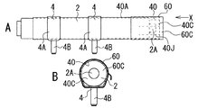
ガス流調整部材40は、図示のように、矩形状のプレート40Aからなる。ガス流調整部材40は、インフレータ2の噴出部2Aを囲む部分に複数のスリット40Jを有する。ガス流調整部材40は、スリット40Jを除いて、第1の実施形態のガス流調整部材30と同様に構成されている。プレート40Aを曲げて筒状に形成する。プレート40Aの両縁部40Bは、突き合わせる。複数のスリット40Jは、ガス流調整部材40の先端部に等間隔に形成されている。スリット40Jは、ガス流調整部材40の一端面(流出口40C側の端面)から他端面に向かって形成されている。
(Eleventh embodiment)
FIG. 33 is a view showing the gas flow adjusting member 40 of the eleventh embodiment.
As shown in the figure, the gas flow adjusting member 40 is composed of a rectangular plate 40A. The gas flow adjusting member 40 has a plurality of slits 40J in a portion surrounding the ejection portion 2A of the inflator 2. The gas flow adjusting member 40 is configured similarly to the gas flow adjusting member 30 of the first embodiment except for the slit 40J. The plate 40A is bent to form a cylinder. Both edges 40B of the plate 40A are abutted. The plurality of slits 40 </ b> J are formed at regular intervals at the distal end portion of the gas flow adjusting member 40. The slit 40J is formed from one end face (end face on the outlet 40C side) of the gas flow adjusting member 40 toward the other end face.

図34は、エアバッグ10に取り付けるインフレータ2を示す図である。図34では、図10と同様に、インフレータ2を側面図と正面図で示す。
ガス流調整部材40は、図示のように、インフレータ2に取り付けられる。ガス流調整部材40の先端部が、インフレータ2の噴出部2Aを囲む。変形抑制部材60は、ガス流調整部材40の先端部に取り付けられる。ガスは流出口40Cから流出する。ガス流調整部材40がガス圧により変形するときに(図8B参照)、ガス流調整部材40の先端部が開くように変形する。同時に、ガス流調整部材40のスリット40J間の部分が、それぞれ外側へ向かって変形する。これにより、ガスの放出部が、ガス流調整部材40に形成される。このガス流調整部材40では、第10の実施形態のガス流調整部材39と同様の効果が得られる。
FIG. 34 is a view showing the inflator 2 attached to the airbag 10. In FIG. 34, the inflator 2 is shown in a side view and a front view as in FIG.
The gas flow adjusting member 40 is attached to the inflator 2 as illustrated. The distal end portion of the gas flow adjusting member 40 surrounds the ejection portion 2 </ b> A of the inflator 2. The deformation suppressing member 60 is attached to the distal end portion of the gas flow adjusting member 40. The gas flows out from the outlet 40C. When the gas flow adjusting member 40 is deformed by the gas pressure (see FIG. 8B), the gas flow adjusting member 40 is deformed so that the front end thereof is opened. At the same time, the portion between the slits 40J of the gas flow adjusting member 40 is deformed outward. Thereby, a gas discharge part is formed in the gas flow adjusting member 40. In this gas flow adjusting member 40, the same effect as the gas flow adjusting member 39 of the tenth embodiment can be obtained.

(第12の実施形態)
図35は、第12の実施形態のガス流調整部材41を示す斜視図である。
ガス流調整部材41は、図示のように、筒状部41Gであるパイプ41Kと、固定部41Eを有する。ガス流調整部材41は、パイプ41Kに複数のスリット41Jを有する。ガス流調整部材41は、パイプ41Kを除いて、第10の実施形態のガス流調整部材39と同様に構成されている。固定部41Eには、2つの挿入孔41Fが形成されている。複数のスリット41Jは、パイプ41Kに等間隔に形成されている。スリット41Jは、パイプ41Kの一端面(流出口41C側の端面)から他端面に向かって形成されている。
(Twelfth embodiment)
FIG. 35 is a perspective view showing a gas flow adjusting member 41 of the twelfth embodiment.
As shown in the drawing, the gas flow adjusting member 41 includes a pipe 41K that is a cylindrical portion 41G and a fixing portion 41E. The gas flow adjusting member 41 has a plurality of slits 41J in the pipe 41K. The gas flow adjusting member 41 is configured similarly to the gas flow adjusting member 39 of the tenth embodiment except for the pipe 41K. Two insertion holes 41F are formed in the fixing portion 41E. The plurality of slits 41J are formed at equal intervals in the pipe 41K. The slit 41J is formed from one end surface (end surface on the outlet 41C side) of the pipe 41K toward the other end surface.

図36は、エアバッグ10に取り付けるインフレータ2を示す図である。図36では、図10と同様に、インフレータ2を側面図と正面図で示す。
ガス流調整部材41(パイプ41K)は、図示のように、インフレータ2の先端部に取り付けられる。パイプ41Kは、インフレータ2の噴出部2Aを囲む。パイプ41Kは、複数のスリット41Jにより、放射状に変形可能になっている。変形抑制部材60は、ガス流調整部材41のパイプ41Kに取り付けられる。変形抑制部材60は、パイプ41Kを覆う。
FIG. 36 is a view showing the inflator 2 attached to the airbag 10. 36, the inflator 2 is shown in a side view and a front view as in FIG.
The gas flow adjusting member 41 (pipe 41K) is attached to the tip of the inflator 2 as shown in the figure. The pipe 41K surrounds the ejection part 2A of the inflator 2. The pipe 41K can be deformed radially by a plurality of slits 41J. The deformation suppressing member 60 is attached to the pipe 41K of the gas flow adjusting member 41. The deformation suppressing member 60 covers the pipe 41K.

図37は、ガス流調整部材41の変形について説明するための斜視図である。
ガス流調整部材41(パイプ41K)は、図37Aに示すように、インフレータ2の噴出部2Aから噴出するガスを受ける。ガスは、流出口41Cから所定方向Fに流出する。変形抑制部材60は、パイプ41Kの変形を抑制することで、放出部41D(図37C参照)の形成を防止する。
FIG. 37 is a perspective view for explaining the deformation of the gas flow adjusting member 41.
As shown in FIG. 37A, the gas flow adjusting member 41 (pipe 41K) receives gas ejected from the ejection portion 2A of the inflator 2. The gas flows out in the predetermined direction F from the outlet 41C. The deformation suppressing member 60 prevents the formation of the discharge part 41D (see FIG. 37C) by suppressing the deformation of the pipe 41K.

変形抑制部材60は、図37Bに示すように、所定温度で変形抑制機能を喪失する。インフレータ2がガスを噴出すると、図37Cに示すように、ガス流調整部材41のパイプ41Kが、ガス圧により変形する。パイプ41Kの全体が外側へ向かって開くように変形する。パイプ41Kのスリット41J間の部分が、それぞれ変形する。パイプ41Kは、放射状に変形する。これにより、ガスの放出部41Dが、ガス流調整部材41に形成される。ガス流調整部材41は、ガス圧により、噴出部2Aのガスの噴出方向の全部を開放して、ガスの放出部41Dを形成する。噴出部2Aの周りの全体が、放出部41Dになり、開放される。ガスは、放出部41Dから放射状に噴出する。   As shown in FIG. 37B, the deformation suppressing member 60 loses the deformation suppressing function at a predetermined temperature. When the inflator 2 ejects gas, as shown in FIG. 37C, the pipe 41K of the gas flow adjusting member 41 is deformed by the gas pressure. The entire pipe 41K is deformed so as to open outward. The portions between the slits 41J of the pipe 41K are deformed. The pipe 41K deforms radially. As a result, a gas discharge part 41 </ b> D is formed in the gas flow adjusting member 41. The gas flow adjusting member 41 opens the entire gas ejection direction of the ejection part 2A by gas pressure to form a gas ejection part 41D. The entire area around the ejection part 2A becomes the discharge part 41D and is opened. The gas is ejected radially from the discharge portion 41D.

このガス流調整部材41では、パイプ41Kの変形により、噴出部2Aの周りの全体を開放できる。また、噴出部2Aのガスの噴出方向の全部を開放することができる。ガスが放出部41Dから多方向に噴出するため、インフレータ2に推進力が働くのを確実に防止できる。ガスによるインフレータ2の移動も小さくできる。そのため、エアバッグ装置1の安全性を、より向上させることができる。   In the gas flow adjusting member 41, the entire area around the ejection portion 2A can be opened by the deformation of the pipe 41K. Moreover, all the gas ejection directions of the ejection part 2A can be opened. Since the gas is ejected from the discharge part 41D in multiple directions, it is possible to reliably prevent the driving force from acting on the inflator 2. The movement of the inflator 2 by gas can also be reduced. Therefore, the safety of the airbag device 1 can be further improved.

(第13の実施形態)
図38は、第13の実施形態のガス流調整部材42を示す斜視図である。
ガス流調整部材42は、図示のように、筒状のパイプ42Kからなる。ガス流調整部材42は、インフレータ2の噴出部2Aを囲む部分に複数のスリット42Jを有する。複数のスリット42Jは、パイプ42Kの先端部に等間隔に形成されている。スリット42Jは、パイプ42Kの一端面(流出口42C側の端面)から他端面に向かって形成されている。
(13th Embodiment)
FIG. 38 is a perspective view showing a gas flow adjusting member 42 of the thirteenth embodiment.
As shown in the figure, the gas flow adjusting member 42 is formed of a cylindrical pipe 42K. The gas flow adjusting member 42 has a plurality of slits 42J in a portion surrounding the ejection part 2A of the inflator 2. The plurality of slits 42J are formed at equal intervals at the tip of the pipe 42K. The slit 42J is formed from one end surface (end surface on the outlet 42C side) of the pipe 42K toward the other end surface.

図39は、エアバッグ10に取り付けるインフレータ2を示す図である。図39では、図10と同様に、インフレータ2を側面図と正面図で示す。
ガス流調整部材42は、図示のように、インフレータ2に取り付けられる。ガス流調整部材42は、2つの固定部材4によりインフレータ2に固定される。パイプ42Kの先端部が、インフレータ2の噴出部2Aを囲む。パイプ42Kの先端部は、複数のスリット42Jにより、放射状に変形可能になっている。変形抑制部材60は、パイプ42Kの先端部に取り付けられる。変形抑制部材60は、パイプ42Kの先端部を覆う。
FIG. 39 is a view showing the inflator 2 attached to the airbag 10. In FIG. 39, the inflator 2 is shown in a side view and a front view as in FIG.
The gas flow adjusting member 42 is attached to the inflator 2 as illustrated. The gas flow adjusting member 42 is fixed to the inflator 2 by the two fixing members 4. The tip of the pipe 42K surrounds the ejection part 2A of the inflator 2. The tip of the pipe 42K can be deformed radially by a plurality of slits 42J. The deformation suppressing member 60 is attached to the tip of the pipe 42K. The deformation suppressing member 60 covers the tip of the pipe 42K.

図40は、ガス流調整部材42の変形について説明するための斜視図である。
ガス流調整部材42(パイプ42K)は、図40Aに示すように、インフレータ2の噴出部2Aから噴出するガスを受ける。ガスは、流出口42Cから所定方向Fに流出する。変形抑制部材60は、パイプ42Kの変形を抑制することで、放出部42D(図40C参照)の形成を防止する。
FIG. 40 is a perspective view for explaining the deformation of the gas flow adjusting member 42.
The gas flow adjusting member 42 (pipe 42K) receives gas ejected from the ejection part 2A of the inflator 2, as shown in FIG. 40A. The gas flows out in the predetermined direction F from the outlet 42C. The deformation suppression member 60 prevents the formation of the discharge portion 42D (see FIG. 40C) by suppressing the deformation of the pipe 42K.

図40B、図40Cに示すように、ガス圧により変形するときに、ガス流調整部材42は、第12の実施形態のガス流調整部材41と同様に変形する。パイプ42Kの先端部は、放射状に変形する。ガス流調整部材42は、ガス圧により変形して、噴出部2Aのガスの噴出方向の全部を開放する。噴出部2Aの周りの全体が、放出部42Dになる。ガスは、放出部42Dから放射状に噴出する。このガス流調整部材42では、第12の実施形態のガス流調整部材41と同じ効果が得られる。   As shown in FIGS. 40B and 40C, when the gas flow adjusting member 42 is deformed by the gas pressure, the gas flow adjusting member 42 is deformed similarly to the gas flow adjusting member 41 of the twelfth embodiment. The tip of the pipe 42K is deformed radially. The gas flow adjusting member 42 is deformed by the gas pressure and opens the entire gas ejection direction of the ejection part 2A. The entire area around the ejection part 2A becomes a discharge part 42D. The gas is ejected radially from the discharge portion 42D. With this gas flow adjusting member 42, the same effect as the gas flow adjusting member 41 of the twelfth embodiment can be obtained.

(第14の実施形態)
図41は、第14の実施形態のガス流調整部材43を示す図である。図41Aは、ガス流調整部材43の斜視図である。図41Bは、ガス流調整部材43の正面図である。図41Cは、図41Bの矢印X方向から見たガス流調整部材43の側面図である。図41Dは、図41BのW−W線で切断したガス流調整部材43の断面図である。図41Eは、図41Bの矢印V方向から見たガス流調整部材43の底面図である。
(Fourteenth embodiment)
FIG. 41 is a view showing a gas flow adjusting member 43 of the fourteenth embodiment. 41A is a perspective view of the gas flow adjusting member 43. FIG. FIG. 41B is a front view of the gas flow adjusting member 43. FIG. 41C is a side view of the gas flow adjusting member 43 as seen from the direction of the arrow X in FIG. 41B. 41D is a cross-sectional view of the gas flow adjusting member 43 cut along the line WW in FIG. 41B. FIG. 41E is a bottom view of the gas flow adjusting member 43 as seen from the direction of arrow V in FIG. 41B.

ガス流調整部材43は、図示のように、キャップ部43Lと固定部43Eを有する。キャップ部43Lは、筒状に形成されている。キャップ部43Lの先端面43Mは、板状部材により塞がれている。ガスの流出口43Cは、キャップ部43Lの筒状部43Gに形成されている。T字状のスリット43N(図41E参照)が、キャップ部43Lに形成されている。流出口43Cとスリット43Nは、筒状部43Gの180°離れた位置に設けられている。固定部43Eは、キャップ部43Lに固定されている。固定部43Eには、2つの挿入孔43Fが形成されている。   The gas flow adjusting member 43 has a cap portion 43L and a fixing portion 43E as shown in the drawing. The cap part 43L is formed in a cylindrical shape. The distal end surface 43M of the cap portion 43L is closed by a plate-like member. The gas outlet 43C is formed in the cylindrical portion 43G of the cap portion 43L. A T-shaped slit 43N (see FIG. 41E) is formed in the cap portion 43L. The outlet 43C and the slit 43N are provided at positions 180 ° apart from the cylindrical portion 43G. The fixing portion 43E is fixed to the cap portion 43L. Two insertion holes 43F are formed in the fixing portion 43E.

図42は、変形抑制部材63を示す斜視図である。
変形抑制部材63は、図示のように、1つの流出孔63Hを有する。変形抑制部材63は、流出孔63Hを除いて、第1の実施形態の変形抑制部材60と同様に構成されている。
FIG. 42 is a perspective view showing the deformation suppressing member 63.
The deformation suppressing member 63 has one outflow hole 63H as illustrated. The deformation suppressing member 63 is configured similarly to the deformation suppressing member 60 of the first embodiment except for the outflow hole 63H.

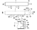
図43は、エアバッグ10に取り付けるインフレータ7を示す図である。図43Aは、インフレータ7の正面図である。図43Bは、図43Aの矢印X方向から見たインフレータ7の側面図である。図43Cは、図43AのW−W線で切断した断面図である。
ガス流調整部材43(キャップ部43L)は、図示のように、インフレータ7の先端部に取り付けられる。キャップ部43Lは、インフレータ7の先端部に被せられる。キャップ部43Lは、インフレータ7の噴出部7Aを囲む。ガス流調整部材43は、固定部43Eにより、インフレータ7に固定される。
FIG. 43 is a view showing the inflator 7 attached to the airbag 10. FIG. 43A is a front view of the inflator 7. 43B is a side view of the inflator 7 as viewed from the direction of the arrow X in FIG. 43A. 43C is a cross-sectional view taken along line WW in FIG. 43A.
The gas flow adjusting member 43 (cap portion 43L) is attached to the distal end portion of the inflator 7 as illustrated. The cap portion 43L is put on the tip portion of the inflator 7. The cap portion 43L surrounds the ejection portion 7A of the inflator 7. The gas flow adjusting member 43 is fixed to the inflator 7 by a fixing portion 43E.

変形抑制部材63は、ガス流調整部材43のキャップ部43Lに取り付けられる。変形抑制部材63は、キャップ部43Lの筒状部43Gを覆う。変形抑制部材63の流出孔63Hの位置を、ガス流調整部材43の流出口43Cの位置に合わせる。ガス流調整部材43は、流出口43Cからガスを流出させる。ガスは、流出口43Cと流出孔63Hを通って流出する。   The deformation suppressing member 63 is attached to the cap portion 43L of the gas flow adjusting member 43. The deformation suppressing member 63 covers the cylindrical portion 43G of the cap portion 43L. The position of the outflow hole 63H of the deformation suppressing member 63 is matched with the position of the outlet 43C of the gas flow adjusting member 43. The gas flow adjusting member 43 causes the gas to flow out from the outlet 43C. The gas flows out through the outlet 43C and the outlet hole 63H.

図44は、インフレータ7のガスの噴出について説明するための図である。図44A、図44Bは、インフレータ7の正面図である。図44Cは、図43BのQ−Q線で切断した断面図である。
インフレータ7は、図44Aに示すように、円柱状の噴出部7Aを有する。噴出部7Aの端面には、ガスの噴出口(図示せず)が形成されている。ガスは、噴出部7Aからインフレータ7の長手方向に噴出する。インフレータ7は、ガスの噴出方向を除いて、上記したインフレータ2と同様に構成されている。
FIG. 44 is a diagram for explaining gas ejection from the inflator 7. 44A and 44B are front views of the inflator 7. 44C is a cross-sectional view taken along line QQ in FIG. 43B.
As shown in FIG. 44A, the inflator 7 has a cylindrical ejection portion 7A. A gas outlet (not shown) is formed on the end face of the ejection portion 7A. The gas is ejected from the ejection portion 7A in the longitudinal direction of the inflator 7. The inflator 7 is configured in the same manner as the inflator 2 described above except for the gas ejection direction.

図44B、図44Cに示すように、ガス流調整部材43は、噴出部7Aから噴出するガスを受ける。ガスは、キャップ部43Lの先端面43Mに当たる。ガスは、流出口43Cから所定方向Fに流出する。ガスの流れる方向は、キャップ部43Lにより変更される。ガスは、キャップ部43Lから一方向に流出する。ガス流調整部材43により、ガスの流れが調整される。   As shown in FIGS. 44B and 44C, the gas flow adjusting member 43 receives the gas ejected from the ejection portion 7A. The gas hits the tip surface 43M of the cap portion 43L. The gas flows out in the predetermined direction F from the outlet 43C. The direction in which the gas flows is changed by the cap portion 43L. The gas flows out from the cap portion 43L in one direction. The gas flow is adjusted by the gas flow adjusting member 43.

図45、図46は、ガス流調整部材43の変形について説明するための図である。図45A、図45Bは、インフレータ7の斜視図である。図45Cは、図45Bに示すガス流調整部材43の底面図である。図46Aは、インフレータ7の斜視図である。図46Bは、図46Aに示すガス流調整部材43の底面図である。図46Cは、図44Cに対応する断面図である。
図45に示すように、ガス流調整部材43の流出口43Cからガスが流出する間、変形抑制部材63は、ガス流調整部材43(キャップ部43L)の変形を抑制する。変形抑制部材63は、ガス流調整部材43のスリット43Nを閉じた状態に維持する。
45 and 46 are diagrams for explaining the deformation of the gas flow adjusting member 43. FIG. 45A and 45B are perspective views of the inflator 7. 45C is a bottom view of the gas flow adjusting member 43 shown in FIG. 45B. FIG. 46A is a perspective view of the inflator 7. 46B is a bottom view of the gas flow adjusting member 43 shown in FIG. 46A. FIG. 46C is a cross-sectional view corresponding to FIG. 44C.
As shown in FIG. 45, while the gas flows out from the outlet 43C of the gas flow adjusting member 43, the deformation suppressing member 63 suppresses the deformation of the gas flow adjusting member 43 (cap portion 43L). The deformation suppressing member 63 maintains the slit 43N of the gas flow adjusting member 43 closed.

図46に示すように、変形抑制部材63は、所定温度で変形抑制機能を喪失する。インフレータ7がガスを噴出すると、ガス流調整部材43のキャップ部43Lが、ガス圧により変形する。キャップ部43Lのスリット43Nを形成した部分が、外側へ向かって開くように変形する。これにより、ガスの放出部43Dが、ガス流調整部材43に形成される。放出部43Dは、三角形状の開口からなる。ガスは、開放された放出部43Dから放出される。ガスが、流出口43Cと放出部43Dから反対方向に噴出するため、インフレータ7に推進力が働くのを防止できる。そのため、エアバッグ装置1の安全性を向上できる。   As shown in FIG. 46, the deformation suppressing member 63 loses its deformation suppressing function at a predetermined temperature. When the inflator 7 ejects gas, the cap portion 43L of the gas flow adjusting member 43 is deformed by the gas pressure. The portion of the cap portion 43L where the slit 43N is formed is deformed so as to open outward. Thereby, the gas discharge part 43 </ b> D is formed in the gas flow adjusting member 43. The discharge portion 43D is formed of a triangular opening. The gas is discharged from the released discharge portion 43D. Since the gas is ejected in the opposite direction from the outlet 43C and the discharge part 43D, it is possible to prevent the driving force from acting on the inflator 7. Therefore, the safety of the airbag apparatus 1 can be improved.

図47は、ガス流調整部材43に形成するスリット43Nの他の例を示す図である。図47は、図41Eに対応するガス流調整部材43の底面図である。
スリット43Nは、図示のように、開放可能な種々の形状に形成される。ガスの放出部43Dは、スリット43Nの形状に応じた形状に形成される。ここでは、矩形状の放出部(図示せず)が、キャップ部43Lに形成される。
FIG. 47 is a view showing another example of the slit 43N formed in the gas flow adjusting member 43. As shown in FIG. FIG. 47 is a bottom view of the gas flow adjusting member 43 corresponding to FIG. 41E.
The slit 43N is formed in various shapes that can be opened as shown in the figure. The gas discharge portion 43D is formed in a shape corresponding to the shape of the slit 43N. Here, a rectangular discharge part (not shown) is formed in the cap part 43L.

なお、ガス供給部13(図2参照)は、エアバッグ10の前後方向の端部に形成してもよい。インフレータ2、7は、エアバッグ10から前方又は後方に突出するガス供給部13に取り付けられる。また、本発明は、カーテンエアバッグ装置に限定されず、インフレータ2、7が取り付けられる種々のエアバッグ装置に適用できる。インフレータ2、7は、パイロ型以外のインフレータ(例えば、ストアードガス型やハイブリッド型のインフレータ)であってもよい。   In addition, you may form the gas supply part 13 (refer FIG. 2) in the edge part of the front-back direction of the airbag 10. As shown in FIG. The inflators 2 and 7 are attached to a gas supply unit 13 that protrudes forward or backward from the airbag 10. The present invention is not limited to the curtain airbag device, and can be applied to various airbag devices to which the inflators 2 and 7 are attached. The inflators 2 and 7 may be inflators other than the pyro type (for example, a stored gas type or a hybrid type inflator).

1・・・エアバッグ装置、2・・・インフレータ、2A・・・噴出部、3・・・バンド、4・・・固定部材、5・・・固定部材、6・・・連結部材、7・・・インフレータ、10・・・エアバッグ、11・・・連結ベルト、12・・・固定布、13・・・ガス供給部、14・・・表基布、15・・・裏基布、16・・・外縁接合部、17・・・内部接合部、20・・・膨張部、21・・・前膨張部、22・・・後膨張部、23・・・連結膨張部、24〜27・・・気室、30〜43・・・ガス流調整部材、60〜63・・・変形抑制部材、90・・・車両、91・・・側壁、92・・・ルーフレール、93・・・フロントピラー、94・・・センターピラー、95・・・前部ドア、96・・・後部ドア、97、98・・・窓、99・・・車体。   DESCRIPTION OF SYMBOLS 1 ... Airbag apparatus, 2 ... Inflator, 2A ... Ejection part, 3 ... Band, 4 ... Fixing member, 5 ... Fixing member, 6 ... Connection member, 7. .... Inflator, 10 ... Airbag, 11 ... Connection belt, 12 ... Fixed cloth, 13 ... Gas supply part, 14 ... Front base cloth, 15 ... Back base cloth, 16 ... outer edge joint part, 17 ... internal joint part, 20 ... expansion part, 21 ... front expansion part, 22 ... rear expansion part, 23 ... connection expansion part, 24-27 ..Air chamber, 30-43 ... Gas flow adjusting member, 60-63 ... Deformation suppressing member, 90 ... Vehicle, 91 ... Side wall, 92 ... Roof rail, 93 ... Front pillar 94 ... Center pillar, 95 ... Front door, 96 ... Rear door, 97, 98 ... Window, 99 ... Body

Claims (11)

ガスを噴出部から噴出するインフレータと、インフレータから供給されるガスにより膨張展開するエアバッグと、を備えたエアバッグ装置であって、
インフレータの噴出部を囲い、噴出部から噴出するガスを流出口から流出させるとともに、ガス圧により変形してガスの放出部を形成するガス流調整部材と、
ガス流調整部材の変形を抑制して放出部の形成を防止する変形抑制機能を有し、エアバッグの膨張展開時における温度よりも高い所定温度で変形抑制機能を喪失する変形抑制部材と、
を備えたエアバッグ装置。
An airbag device comprising: an inflator that ejects gas from an ejection part; and an airbag that is inflated and deployed by gas supplied from the inflator,
A gas flow adjusting member that surrounds the ejection portion of the inflator, causes the gas ejected from the ejection portion to flow out from the outlet, and is deformed by gas pressure to form a gas ejection portion;
A deformation suppressing member that has a deformation suppressing function that suppresses the deformation of the gas flow adjusting member and prevents the formation of the discharge portion, and loses the deformation suppressing function at a predetermined temperature higher than the temperature at the time of inflation and deployment of the airbag;
An airbag device comprising:
請求項1に記載されたエアバッグ装置において、
変形抑制部材が、エアバッグの膨張展開時における温度よりも高い温度の熱をエアバッグ装置の外部から受けたときに破損して変形抑制機能を喪失するエアバッグ装置。
In the airbag apparatus described in Claim 1,
An airbag device in which a deformation suppression member loses its deformation suppression function when it receives heat from the outside of the airbag device when it receives heat at a temperature higher than the temperature when the airbag is inflated and deployed.
請求項1又は2に記載されたエアバッグ装置において、
変形抑制部材が、ガス流調整部材の周りに取り付けられた筒状部材からなるエアバッグ装置。
In the airbag apparatus described in Claim 1 or 2,
The airbag apparatus which a deformation | transformation suppression member consists of a cylindrical member attached around the gas flow adjustment member.
請求項1ないし3のいずれかに記載されたエアバッグ装置において、
ガス流調整部材が、ガス圧により、噴出部のガスの噴出方向の一部又は全部を開放して放出部を形成するエアバッグ装置。
In the airbag apparatus as described in any one of Claim 1 thru | or 3,
An airbag device in which a gas flow adjusting member opens a part or all of a gas jetting direction of a jetting part by a gas pressure to form a discharge part.
請求項1ないし4のいずれかに記載されたエアバッグ装置において、
ガス流調整部材が、筒状に形成され、インフレータに取り付けられたプレートからなるエアバッグ装置。
In the airbag apparatus as described in any one of Claim 1 thru | or 4,
The airbag apparatus which consists of a plate in which the gas flow adjustment member was formed in the cylinder shape, and was attached to the inflator.
請求項5に記載されたエアバッグ装置において、
プレートの両縁部を重ね合わせたエアバッグ装置。
In the airbag apparatus described in Claim 5,
An airbag device in which both edges of the plate are overlapped.
請求項1ないし6のいずれかに記載されたエアバッグ装置において、
ガス流調整部材が、インフレータに固定される固定部を有するエアバッグ装置。
In the airbag apparatus described in any one of Claims 1 thru | or 6,
The airbag apparatus which has a fixing | fixed part with which a gas flow adjustment member is fixed to an inflator.
請求項1ないし7のいずれかに記載されたエアバッグ装置において、
変形抑制部材をガス流調整部材に連結する連結部材を備えたエアバッグ装置。
In the airbag apparatus as described in any one of Claim 1 thru | or 7,
An airbag device comprising a connecting member for connecting the deformation suppressing member to the gas flow adjusting member.
請求項1ないし8のいずれかに記載されたエアバッグ装置において、
ガス流調整部材が、インフレータの噴出部を囲む部分に複数のスリットを有するエアバッグ装置。
In the airbag apparatus described in any one of Claims 1 thru | or 8,
An airbag device in which the gas flow adjusting member has a plurality of slits in a portion surrounding the ejection portion of the inflator.
請求項9に記載されたエアバッグ装置において、
ガス流調整部材が、インフレータの噴出部を囲い、複数のスリットにより放射状に変形可能なパイプを有するエアバッグ装置。
The airbag device according to claim 9, wherein
An air bag apparatus in which a gas flow adjusting member includes a pipe that surrounds an ejection portion of an inflator and is radially deformable by a plurality of slits.
請求項1ないし10のいずれかに記載されたエアバッグ装置において、
変形抑制部材が、エアバッグ用の基布からなるエアバッグ装置。
In the airbag apparatus described in any one of Claims 1 thru | or 10,
An airbag device in which the deformation suppressing member is made of a base fabric for an airbag.
JP2011248624A 2011-11-14 2011-11-14 Airbag device Pending JP2013103608A (en)

Priority Applications (1)

Application Number Priority Date Filing Date Title
JP2011248624A JP2013103608A (en) 2011-11-14 2011-11-14 Airbag device

Applications Claiming Priority (1)

Application Number Priority Date Filing Date Title
JP2011248624A JP2013103608A (en) 2011-11-14 2011-11-14 Airbag device

Publications (1)

Publication Number Publication Date
JP2013103608A true JP2013103608A (en) 2013-05-30

Family

ID=48623494

Family Applications (1)

Application Number Title Priority Date Filing Date
JP2011248624A Pending JP2013103608A (en) 2011-11-14 2011-11-14 Airbag device

Country Status (1)

Country Link
JP (1) JP2013103608A (en)

Cited By (1)

* Cited by examiner, † Cited by third party
Publication number Priority date Publication date Assignee Title
DE102016104103A1 (en) * 2016-03-07 2017-09-07 Takata AG Gas generator assembly and method of manufacturing a gas generator assembly

Citations (3)

* Cited by examiner, † Cited by third party
Publication number Priority date Publication date Assignee Title
JP2008517825A (en) * 2004-11-01 2008-05-29 オートリブ ディベロップメント アクティエボラーグ Airbag apparatus having a breakable connecting portion between a gas generator and a non-metallic gas lance
JP2009517275A (en) * 2005-12-01 2009-04-30 タカタ・ペトリ アーゲー Gas distribution device for airbag modules
JP2009214615A (en) * 2008-03-07 2009-09-24 Ashimori Ind Co Ltd Airbag device

Patent Citations (3)

* Cited by examiner, † Cited by third party
Publication number Priority date Publication date Assignee Title
JP2008517825A (en) * 2004-11-01 2008-05-29 オートリブ ディベロップメント アクティエボラーグ Airbag apparatus having a breakable connecting portion between a gas generator and a non-metallic gas lance
JP2009517275A (en) * 2005-12-01 2009-04-30 タカタ・ペトリ アーゲー Gas distribution device for airbag modules
JP2009214615A (en) * 2008-03-07 2009-09-24 Ashimori Ind Co Ltd Airbag device

Cited By (1)

* Cited by examiner, † Cited by third party
Publication number Priority date Publication date Assignee Title
DE102016104103A1 (en) * 2016-03-07 2017-09-07 Takata AG Gas generator assembly and method of manufacturing a gas generator assembly

Similar Documents

Publication Publication Date Title
JP6398430B2 (en) Curtain airbag and curtain airbag device
JP5883613B2 (en) Airbag device
US20110127755A1 (en) Airbag device
US9205801B2 (en) Airbag module including airbag with diffuser
EP3118068B1 (en) Pedestrian protection air-bag device
EP1944201B1 (en) Occupant leg part restraining apparatus and retainer
US7909357B2 (en) Airbag apparatus
JP6455365B2 (en) Seat cushion airbag device
US9409543B2 (en) Variable trajectory side curtain airbags
US20140028006A1 (en) Variable volume airbag
JP5743722B2 (en) Airbag device
JP5187831B2 (en) Airbag device
JP5435913B2 (en) Airbag device
JP2013103608A (en) Airbag device
JP5822702B2 (en) Curtain airbag device
JP5766577B2 (en) Airbag device
JP5530747B2 (en) Gas rectifier
EP2233371B1 (en) Head protection airbag device
WO2012124549A1 (en) Airbag device
JP5675493B2 (en) Airbag device
JP4890432B2 (en) Airbag device
JP5414089B2 (en) Airbag device
JP2020142635A (en) Heat-proof reinforcement member for air-bag
JP2015054561A (en) Airbag

Legal Events

Date Code Title Description
A621 Written request for application examination

Free format text: JAPANESE INTERMEDIATE CODE: A621

Effective date: 20141030

A977 Report on retrieval

Free format text: JAPANESE INTERMEDIATE CODE: A971007

Effective date: 20150828

A131 Notification of reasons for refusal

Free format text: JAPANESE INTERMEDIATE CODE: A131

Effective date: 20150901

A02 Decision of refusal

Free format text: JAPANESE INTERMEDIATE CODE: A02

Effective date: 20160105