JP2013103142A - Vibration device - Google Patents
Vibration device Download PDFInfo
- Publication number
- JP2013103142A JP2013103142A JP2011246499A JP2011246499A JP2013103142A JP 2013103142 A JP2013103142 A JP 2013103142A JP 2011246499 A JP2011246499 A JP 2011246499A JP 2011246499 A JP2011246499 A JP 2011246499A JP 2013103142 A JP2013103142 A JP 2013103142A
- Authority
- JP
- Japan
- Prior art keywords
- mover
- bottom plate
- vibration device
- bearing
- circular motion
- Prior art date
- Legal status (The legal status is an assumption and is not a legal conclusion. Google has not performed a legal analysis and makes no representation as to the accuracy of the status listed.)
- Pending
Links
Images


Landscapes
- Reciprocating, Oscillating Or Vibrating Motors (AREA)
- Apparatuses For Generation Of Mechanical Vibrations (AREA)
Abstract
Description
本発明は、機械的な振動を発生する振動装置に関する。 The present invention relates to a vibration device that generates mechanical vibration.
振動により着信を知らせる携帯電話のマナーモード等を実現するための装置として各種の振動装置が知られている。特に搭載する機器(例えば、携帯電話)が薄型化されるのに従い、より薄型の振動装置が求められている。薄型化に適した振動装置として、可動子(振動子)が振子のように往復運動する形態のものが知られている。例えば、特許文献1には、外周に着磁が行われた可動子、この可動子の外周面から隙間を隔てた位置に設けられた固定子側の複数の突極を備え、固定子側の突極の極性を切替えることで、可動子に軸を中心にした振子運動を行わせ、振動を発生させる構成が記載されている。特許文献2および3には、直線上の往復運動が可能で着磁された可動子の前後をバネで支え、可動子の運動方向と平行な面に配置されたコイルに電流を流すことで、可動子とコイルとの間にローレンツ力を作用させ、その反力で可動子を直線上の前後に往復運動させる構成が記載されている。
Various types of vibration devices are known as devices for realizing a manner mode or the like of a cellular phone that notifies an incoming call by vibration. In particular, as a device to be mounted (for example, a mobile phone) is made thinner, a thinner vibration device is required. 2. Description of the Related Art As a vibration device suitable for a reduction in thickness, a device in which a movable element (vibrator) reciprocates like a pendulum is known. For example,
特許文献1に記載の構造では、可動子側の磁石と固定子側の突極との間で作用する磁力の吸引および反発力を利用して振動を生じさせている。この構造では、インダクタンスが大きいため、左右揺動の可動子の振動の周波数が上げられず、また共振させるための振動の周波数の調整が困難である問題がある。また、突極にコイルを巻回した構造が必要とされるので、小型化および薄型化に限界がある。
In the structure described in
特許文献2および3に記載の構造は、直線上を往復運動する可動子の前後をバネで支えているが、このバネから発生する弾性力は、可動子が中心点を超えてから、可動子の前進方向と逆になり、運動を妨げようとする。そのため、このバネにより可動子の最高速度が制限され、加振力を大きくできない。すなわち、直線上における物体の往復運動によって振動を発生させる場合、移動の方向を反転させる時点における速度ができるだけ大きく、またその反転に要する時間が極力短いことが大きな振動を発生させる要件となる。しかしながら、上記の可動子をその移動方向の前後からバネで支える構造は、往復運動の端の部分に行く程、バネの反発力および吸引力が強くなり、可動子の速度が低下する。またバネにより緩やかに移動方向の反転が行われるので、可動子の方向転換に要する時間が必然的に長くなる。このため、保持用のバネにより、加振力を抑え込もうとする作用が働き、加振力が弱く、振動の発生効率が低い。この問題を低減するにはバネを弱くすればよいが、磁場を強くし且つ磁束の漏れを防ぐため、コイル底にケースやバックヨークなど磁性材料が設置されてあり、そうすると可動子が固定子のコイル側に引き寄せられる磁力に負けて、可動子が固定子に接触する問題が生じる。このため、可動子を支えるバネはある程度強くなくてはならない。しかしそうすると、上述したようにバネによる振動を抑制する作用が顕在化する。また、特許文献2および3に記載の構造において、可動子を支えるバネを弱くし、それに伴う可動子と固定子側コイルとの接触を避けるために、可動子とコイルとの間の隙間を確保する構造も考えられるが、そうするとこの確保した隙間が薄型化の障害となる。また、可動子を支えるバネを弱くすると、構造的に弱くなり、信頼性が低下する。
In the structures described in
このような背景において、本発明は、薄型化に適し、大きな加振力が得られ、更に効率よく振動が生じる振動装置を提供することを目的とする。 In such a background, an object of the present invention is to provide a vibration device that is suitable for thinning, can obtain a large excitation force, and generates vibration more efficiently.
請求項1に記載の発明は、底板と、前記底板に対して往復する円運動が可能であり、前記円運動の回転軸の中心からずれた位置に重心が設けられ、複数の磁極を備えた可動子と、前記底板に固定されたコイルと、前記可動子の前記複数の磁極が生成する磁場と前記コイルに流れる電流との間で作用するローレンツ力により前記可動子の前記往復する円運動が生じ、前記コイルに流れる電流の向きを切替えることにより前記可動子の前記往復する円運動の方向を切替する手段とを備え、前記可動子が前記回転軸を中心とした往復する円運動を行うことを特徴とする振動装置である。
The invention according to
ここで、回転軸というのは、回転するものの回転中心のことである。往復する円運動とは、円弧の曲率中心を中心として、この円弧に沿って往復する運動のことをいう。 Here, the rotation axis is the center of rotation of the rotating object. The reciprocating circular motion refers to a reciprocating motion along the arc around the center of curvature of the arc.
請求項1に記載の発明によれば、可動子は、通電されたコイルからの電磁力で回転軸を中心として円運動を行い、通電方向が逆にされることで、コイルから発生する逆方向への電磁力で逆方向へ円運動を行う。そして、コイルへの通電の切り替えが繰り返し行われることで、往復する円運動を行う。この可動子の往復する円運動により振動が発生する。可動子の円運動の周期、即ち、振動装置の振動周波数は、可動子の可動角度範囲を変更することで調整できる。例えば、携帯電話など搭載する機器の固有振動周波数が分かれば、可動子の可動角度範囲を調整することで、振動時に共振が生じ、より強い振動が発生する状態にすることができる。運動の際、可動子の動きを規制するのは、回転自在な状態で可動子を保持する軸受け部分の摩擦抵抗が主であり、振幅の大きさに比例して振動を押さえ込むような力は存在しない。このため、可動子が可動角度範囲において常に加速され、最も振れた位置における可動子の速度(回転速度)を大きくでき、大きな加振力が得られる。また、上述したように振動を抑え込む力が存在しないので、駆動に要した投入エネルギー(投入電力)が振動以外に消費される割合が小さく、効率よく振動を生じさせることができる。 According to the first aspect of the present invention, the mover performs a circular motion around the rotation axis by the electromagnetic force from the energized coil, and the energization direction is reversed, so that the reverse direction generated from the coil. Performs a circular motion in the opposite direction by the electromagnetic force applied to And the reciprocating circular motion is performed by repeatedly switching the energization to the coil. Vibration is generated by the reciprocating circular motion of the mover. The period of the circular movement of the mover, that is, the vibration frequency of the vibration device can be adjusted by changing the movable angle range of the mover. For example, if the natural vibration frequency of a device such as a mobile phone is known, the movable angle range of the mover can be adjusted so that resonance occurs during vibration and a stronger vibration can be generated. During movement, the movement of the mover is mainly controlled by the frictional resistance of the bearing that holds the mover in a rotatable state, and there is a force that suppresses vibration in proportion to the amplitude. do not do. For this reason, the mover is always accelerated in the movable angle range, the speed (rotational speed) of the mover at the most shaken position can be increased, and a large excitation force can be obtained. Further, as described above, since there is no force for suppressing the vibration, the ratio of the input energy (input power) required for driving to be consumed other than the vibration is small, and the vibration can be generated efficiently.
請求項1に記載の発明において、底板側に固定されたコイルに電流が流れると、この電流と可動子側の磁極が生成する磁束との間でローレンツ力が働く。コイルは底板に固定されているので、このローレンツ力の反力が可動子に加わり、上述した可動子の回転が生じる。そしてコイルに流す電流の向きを繰り返し切り替えることで、可動子の往復する円運動が生じる。 In the first aspect of the present invention, when a current flows through the coil fixed to the bottom plate side, a Lorentz force acts between this current and the magnetic flux generated by the magnetic pole on the mover side. Since the coil is fixed to the bottom plate, the reaction force of this Lorentz force is applied to the mover, and the above-described rotation of the mover occurs. The reciprocating circular motion of the mover occurs by repeatedly switching the direction of the current flowing through the coil.
請求項1に記載の発明において、底板の構造として磁性材料を含む構造とし、可動子の磁極が生成する磁束の磁路が底板に形成されるようにしてもよい。このような底板としては、底板そのものを磁性材料(例えば、SPCC鋼板等の各種の磁性鋼板)により構成する構造、あるいは底板のベースとなる板状の部分を樹脂等の非磁性材料で構成し、その表面にニッケルなど磁性材料をコーティングした構造、非磁性材料のステンレス鋼板材の表面に磁性材料をコーティングした構造を挙げることができる。 In the first aspect of the present invention, the bottom plate may include a magnetic material, and a magnetic path of magnetic flux generated by the magnetic poles of the mover may be formed on the bottom plate. As such a bottom plate, the bottom plate itself is made of a magnetic material (for example, various magnetic steel plates such as SPCC steel plate), or the plate-like portion that is the base of the bottom plate is made of a non-magnetic material such as a resin, Examples thereof include a structure in which a magnetic material such as nickel is coated on the surface, and a structure in which a magnetic material is coated on the surface of a non-magnetic stainless steel plate.
また、この底板は、当該振動装置から外部への漏れ磁束を抑える磁気シールドとしても機能する。例えば、携帯電話に本発明を利用した振動装置を内蔵させた場合、近接して高周波回路やデジタル回路が配置される可能性が高いが、振動装置からの漏れ磁束が大きいと、漏れ磁束によるそれら回路への悪影響が懸念される。磁性材料を含む材質で底板を構成することで、底板により漏れ磁束が抑えられ、他の回路への漏れ磁束の悪影響の問題が抑制される。 The bottom plate also functions as a magnetic shield that suppresses leakage magnetic flux from the vibration device to the outside. For example, when a vibration device using the present invention is built in a mobile phone, there is a high possibility that a high-frequency circuit or a digital circuit will be arranged in the vicinity. However, if the leakage magnetic flux from the vibration device is large, those due to the leakage magnetic flux There are concerns about adverse effects on the circuit. By configuring the bottom plate with a material including a magnetic material, the leakage flux is suppressed by the bottom plate, and the problem of adverse effects of the leakage flux on other circuits is suppressed.
請求項1に記載の発明において、前記可動子は板状の構造を有し、前記可動子の前記コイルに対向した面と反対の面の側には、磁性材料により構成され、前記複数の磁極のバックヨークとして機能するバックヨーク部が配置されている構造も好ましい。バックヨーク部を設けることで、可動子の磁極は効率よく磁束を生成することができ、また磁極が生成する磁束の外部への漏れ出しが抑えられる。
The invention according to
バックヨーク部の構造としては、可動子の磁極の背後に磁性材料の板材を取り付けた構造が挙げられる。また、可動子から隙間を隔てた位置にバックヨーク部として機能する磁性材料の板材を配置してもよい。この場合、バックヨーク部が可動子から離れた構造となるが、機能としては磁極の背後に磁路を形成するバックヨークとして機能する。 As a structure of the back yoke portion, a structure in which a magnetic plate is attached behind the magnetic pole of the mover can be mentioned. Further, a magnetic material plate functioning as a back yoke portion may be disposed at a position spaced from the mover. In this case, the back yoke portion is structured away from the mover, but functions as a back yoke that forms a magnetic path behind the magnetic pole.
請求項2に記載の発明は、請求項1に記載の発明において、前記可動子の可動範囲を制限するストッパが前記底板に対して固定されていることを特徴とする。 According to a second aspect of the present invention, in the first aspect of the present invention, a stopper for limiting a movable range of the movable element is fixed to the bottom plate.
請求項2に記載の発明によれば、可動子が接触するストッパに衝撃を与えると同時にストッパから反発力を受け、その際に可動子の運動の方向が反転する。この動きが繰り返されることで、可動子の往復する円運動が行われる。また、往復する円運動を行う可動子がストッパに繰り返し衝突することで、衝撃が繰り返し発生し、振動装置の振動が生じる。ストッパとして弾性材料を用いると、可動子がストッパに接触する際の衝撃音を抑えることができる。また、ストッパとして弾性体ではなく剛体と見なせる材料(例えば鋼材)を用いると、衝撃の際に吸収される振動のエネルギーが抑えられ、振動時に周期的に発生する衝突音および衝撃感を得ることができる。 According to the second aspect of the present invention, an impact is applied to the stopper with which the movable element contacts, and at the same time, a repulsive force is received from the stopper, and the direction of movement of the movable element is reversed at that time. By repeating this movement, the reciprocating circular movement of the mover is performed. Further, when the movable element that performs the reciprocating circular motion repeatedly collides with the stopper, the impact is repeatedly generated, and the vibration of the vibration device is generated. When an elastic material is used as the stopper, it is possible to suppress an impact sound when the mover contacts the stopper. In addition, if a material that can be regarded as a rigid body instead of an elastic body (for example, steel) is used as the stopper, the energy of vibration absorbed at the time of impact can be suppressed, and the impact sound and impact sensation that occur periodically during vibration can be obtained. it can.
請求項3に記載の発明は、請求項1または2に記載の発明において、前記可動子の角度位置を検出する手段を備え、前記検出した角度位置に基づいて前記コイルへの通電の極性の切替えが行われることを特徴とする。 According to a third aspect of the present invention, in the first or second aspect of the invention, there is provided means for detecting an angular position of the mover, and switching of the polarity of energization to the coil based on the detected angular position. Is performed.
請求項3に記載の発明によれば、可動子が往復運動の端の部分に到達したこと、あるいは移動の方向を切り替えるタイミングの角度位置に到達している状態が検出手段により検出され、それに基づいてコイルに流れる電流の極性(向き)が切り替わり、可動子の移動方向が反転する。これにより、可動子の往復運動が持続して行われる。可動子の位置を検出する検出手段としては、インダクタンスの変化により可動子の位置を検出するセンサーレス制御というもの、可動子の位置を磁気的に検出するホール素子を用いたもの、可動子に接触する機械的なスイッチ、可動子のストッパへの接触を検出する素子やスイッチ、光学的あるいは磁気的に可動子の位置を検出する構成、その他これらを組み合わせた構成を挙げることができる。 According to the third aspect of the present invention, the detection means detects that the mover has reached the end of the reciprocating motion, or has reached the angular position at the timing of switching the movement direction. The polarity (direction) of the current flowing through the coil is switched, and the moving direction of the mover is reversed. Thereby, the reciprocating motion of the mover is continuously performed. The detection means for detecting the position of the mover includes sensorless control that detects the position of the mover by a change in inductance, a Hall element that magnetically detects the position of the mover, and contact with the mover. And a mechanical switch that detects contact of the movable element to the stopper, a structure that detects the position of the movable element optically or magnetically, and a combination of these.
請求項4に記載の発明は、請求項1乃至3のいずれか一項に記載の発明において、前記底板に固定された軸を備え、前記可動子は前記軸を中心として往復する円運動が可能であることを特徴とする。 According to a fourth aspect of the present invention, in the invention according to any one of the first to third aspects, the shaft includes a shaft fixed to the bottom plate, and the movable element can reciprocate around the shaft. It is characterized by being.
請求項5に記載の発明は、請求項4に記載の発明において、前記可動子には、前記軸を保持する軸受の少なくとも一部を収容する収容領域が形成され、該収容領域に前記軸受の少なくとも一部が収容された状態において、前記可動子は前記軸を中心とした往復する円運動が可能であることを特徴とする。請求項5に記載の発明によれば、軸受の少なくとも一部が収容領域に収容されるので、軸が延在する方向において軸受が占めるスペースが節約され、振動装置を薄型化できる。ここで、軸受には、転がり軸受、滑り軸受、それら軸受を構成する部材の一部が含まれる。これは、請求項6以下の発明においても同じである。
According to a fifth aspect of the present invention, in the invention according to the fourth aspect, the mover is formed with a housing region that houses at least a part of a bearing that holds the shaft, and the housing region includes the housing. In a state in which at least a part is accommodated, the movable element is capable of reciprocating circular movement around the axis. According to the fifth aspect of the present invention, since at least a part of the bearing is accommodated in the accommodating region, the space occupied by the bearing in the direction in which the shaft extends can be saved, and the vibration device can be thinned. Here, the bearing includes a rolling bearing, a sliding bearing, and a part of members constituting these bearings. This is the same in the inventions of
請求項6に記載の発明は、請求項1乃至3のいずれか一項に記載の発明において、前記可動子に固定された軸と、前記底板に対して向かい合わせに配置された天板とを備え、前記底板には、前記軸を保持する第1の軸受の少なくとも一部を収容する第1の収容領域が形成され、前記天板には、前記軸を保持する第2の軸受の少なくとも一部を収容する第2の収容領域が形成され、前記第1の収容領域に前記第1の軸受の少なくとも一部が収容され、且つ、前記第2の収容領域に前記第2の軸受の少なくとも一部が収容された状態において、前記可動子は前記軸を中心とした往復する円運動が可能であることを特徴とする。
The invention according to
請求項6に記載の発明によれば、向かい合わせに配置された底板と天板のそれぞれに軸受を収容する収容領域が設けられるので、軸受が占めるスペースが節約され、振動装置をより薄型化できる。 According to the sixth aspect of the present invention, since the receiving area for receiving the bearing is provided in each of the bottom plate and the top plate that are arranged face to face, the space occupied by the bearing is saved, and the vibration device can be made thinner. .
請求項7に記載の発明は、請求項1乃至3のいずれか一項に記載の発明において、前記底板に対して向かい合わせに配置された天板を備え、前記底板および前記可動子に接触し、且つ、前記底板および前記可動子に対して前記回転軸を中心とする円周の方向に転がり、スラスト方向の荷重を保持するベアリングボールと、前記天板および前記可動子に接触し、且つ、前記天板および前記可動子に対して前記回転軸を中心とする円周の方向に転がり、スラスト方向の荷重を保持するベアリングボールとを備え、前記可動子は、前記底板と前記天板の間において、往復する円運動が可能な状態で保持されていることを特徴とする。
The invention according to
ここで、円周の方向というのは、円周を構成する曲線が延長する方向という意味で用いている。請求項7に記載の発明では、ベアリングボールにより、可動子が、回転軸を回転中心として往復する円運動が可能な状態で底板と天板との間で保持される。この構成では、ベアリングボールが可動子と底板とに接触し、また可動子と天板とに接触するので、部品点数が削減され、また薄型化が可能となる。ここで、ベアリングボールとしては、球形のベアリングボールが挙げられるが、回転軸を中心とした円周の方向に沿って転がることができる形状であれば、必ずしも球形に限定されない。 Here, the direction of the circumference is used to mean the direction in which the curve constituting the circumference extends. According to the seventh aspect of the present invention, the mover is held between the bottom plate and the top plate by the bearing ball in a state in which the mover can reciprocate around the rotation axis. In this configuration, the bearing balls are in contact with the mover and the bottom plate, and are also in contact with the mover and the top plate, so that the number of parts can be reduced and the thickness can be reduced. Here, the bearing ball may be a spherical bearing ball, but is not necessarily limited to a spherical shape as long as it can roll along a circumferential direction around the rotation axis.
本発明によれば、薄型化に適し、大きな加振力が得られ、更に効率よく振動が生じる振動装置が提供される。 ADVANTAGE OF THE INVENTION According to this invention, the vibration apparatus which is suitable for thickness reduction, a big excitation force is obtained, and a vibration generate | occur | produces more efficiently is provided.
1.第1の実施形態
(構造)
図1には、実施形態の振動装置100が分解された状態が示されている。振動装置100は、磁性材料の鋼材により構成されたケース本体101を有している。ケース本体101は、振動装置100の筐体(ケーシング)となる部分である。ケース本体101は、上面が開放された厚みの薄い略箱型の構造を有し、周囲を囲む側板102、側板102で囲まれた部分の底の部分に蓋をする底板103により構成されている。底板103上には、コイル104と105が固定されている。
1. First embodiment (structure)
FIG. 1 shows a state where the
コイル104は、底板103に垂直な方向から見て概略三角形状を有し、回転軸(軸ピン107の中心)から離れる方向に沿って延在した第1の延在部104aと第2の延在部104b、第1の延在部104aと第2の延在部104bを外周側で繋ぐ回転軸を中心とした円周の方向に沿った外周部104c、第1の延在部104aと第2の延在部104bを内周側で繋ぐ内周部104dを有している。コイル105もコイル104と同様な形状を有し、回転軸から離れる方向に沿って延在した第1の延在部105aと第2の延在部105b、第1の延在部105aと第2の延在部105bを外周側で繋ぐ当該円周の方向に沿った外周部105c、第1の延在部105aと第2の延在部105bを内周側で繋ぐ内周部105dを有している。なお、コイル104,105は共に線材を複数回巻いた構造を有している。ここで、外周部104c,105cは、内周部104d,105dよりも当該円周の方向における長さが長い。コイル104,105は、プリント配線を用いて構成することも可能である。
The
底板103には、固定ピン106と軸ピン107が固定されている。固定ピン106には、ストッパ部材108が取り付けられている。ストッパ部材108は、一対のストッパ部109と110を有している。ストッパ部109と110は、金属性の板バネを加工したもので構成され、バネ性(弾性)を有している。なお、ストッパ部109と110を剛体と見なせる材質に変更することも可能である。
A fixing
軸ピン107は、後述する可動子120の回転軸となる位置に配置された軸の一例であり、軸受の一例であるボールベアリング111が取り付けられている。図面では詳細が省略されているが、ボールベアリング111は、内輪と、内輪に対して相対的に回転が自在な状態の外輪を有しており、軸ピン107は、内輪の内側に固定されている。そしてボールベアリング111の外輪には、可動子120が固定されている。この構造により、可動子120は、軸ピン107を中心とした回転が可能な状態で、ケース本体101に対して保持されている。なお、ボールベアリング111の代わりに滑り軸受を採用することも可能である。
The
軸ピン107と固定ピン106を利用して、ケース本体101の上部の開放部分に天板130が取り付けられている。天板130は、蓋材となる磁性材料である鋼材により構成された板状の部材である。天板130は、ケース本体101と一体化されてケース本体101の筐体(ケーシング)を構成する。天板130には、ピン固定孔131,132が設けられており、ピン固定孔131に軸ピン107が嵌り、ピン固定孔132に固定ピン106が嵌ることで、天板130のケース本体101への固定が行われている。
A
可動子120は、振動子として機能する部材であり、非磁性の金属材料により構成され、略扇形の概略板状の形状を有している。上述したように、可動子120は、ボールベアリング111により軸ピン107に回転自在な状態で保持されている。軸ピン107は、可動子120の回転軸となる位置にあり、また可動子120における略扇形の頂点の位置にある。また、可動子120の重心は、軸ピン107から突起部126の方向にずれた位置にある。なお、略扇形の頂点の位置とは、扇形を構成する円弧の曲率中心の位置として定義される。また、可動子120は、コイル104,105に接触しないように、コイル104,105との間に隙間を有し、且つ、天板130に接触しないように、天板130との間に隙間を有した位置に保持されている。
The
図2に、図1に示されている面の裏面側が見える状態で、可動子120が示されている。可動子120の回転軸となる位置には、軸受の少なくとも一部を収容する収容領域の一例である軸孔121が設けられ、この軸孔121にボールベアリング111の外輪が固定されている。ボールベアリング111は、軸孔121に完全に納まる形態であってもよいし、その一部が軸孔121に納まる形態であってもよい。可動子120には、回転軸を中心とした円周の方向に沿って、交互に極性が反転した状態の磁石122,123,124が取り付けられている。磁石122,123,124は、表裏の方向で着磁された薄型の永久磁石であり、可動子120側の磁極を構成する。
FIG. 2 shows the
図示するように、磁石122と隣接する磁石123とは、互いに極性が反転し、磁石123と隣接する磁石124とは、互いに極性が反転する状態とされている。可動子120には、磁石122〜124を嵌め込むための開口部が形成され、そこに磁石122,123,124が嵌め込まれて固定されている。磁石122,123,124の磁極面、すなわち、磁石122のS極の面、磁石123のN極の面、磁石124のS極の面は、それぞれ環状のコイル104および105と対向することが可能とされている。
As shown in the drawing, the polarity of the
また可動子120は、符号125の部分で掘り下げられており、厚みが薄くなっている。この符号125で示す掘り下げた部分にコイル104,105が可動子120に接触しない状態で収まる。こうすることで、より薄型化が図られている。
Moreover, the needle |
可動子120の先端には、回転軸(軸ピン107の位置)から離れる方向に突出した突起部126が設けられている。突起部126がストッパ部109に接触することで、図1の視点から見た可動子120の時計回り方向への回転が制限され、突起部126がストッパ部110に接触することで、図1の視点から見た可動子120の反時計回り方向への回転が制限される。つまり、突起部126は、ストッパ部109と110との間で移動が可能であり、その範囲において、可動子120は、軸ピン107の位置を中心とした往復する円運動、つまり軸ピン107を中心として、この中心を曲率中心とする円弧上を往復する運動が可能とされている。突起部126とストッパ部109,110との接触は、後述するローレンツ力による可動子120への駆動力が効果的に作用する範囲で設定されている。
A
図1に示す構造において、磁性材料により構成される底板103は、可動子120側の磁極を構成する磁石122,123,124が生成する磁束の磁路が形成されるヨークとして機能する。また、底板103は、磁石122〜124が生成する磁束およびコイル104,105が生成する磁束が振動装置100の外側に漏れ出ないようにする磁気シールドとしても機能する。また、天板130は、磁性材料である鋼材により構成されており、可動子120に取り付けられた磁石122,123,124のバックヨーク、および底板103と同様な磁気シールドとして機能する。
In the structure shown in FIG. 1, the
可動子120を回転自在な状態で支える構造は、例示した構造、つまり軸側が固定され、この軸に可動子120が回転自在な状態で取り付けられる構造に限定されず、可動子120に軸が固定され、この軸が軸受によってケース本体101に回転自在な状態で取り付けられる構造であってもよい。
The structure that supports the
(動作原理)
図3は、動作原理を説明する斜視図である。図3には、図1の振動装置100から天板130、可動子120、ボールベアリング111を外した状態が示されている。図3において、X−Y平面が底板103の面であり、Z方向が軸ピン107の延在方向である。また、X方向は、軸ピン107から固定ピン106の方向に一致させてある。図4には、図3におけるX方向に向かって見た視点におけるコイル104,105の断面部分が概念的に示されている。なお、図4の横軸は、軸ピン107を中心とした円周の方向140(図3参照)で展開したものとしている。
(Operating principle)
FIG. 3 is a perspective view for explaining the principle of operation. FIG. 3 shows a state where the
図5(A)には、フレミングの左手の法則で知られる磁場中において電流に作用するローレンツ力について概念的に示されている。図5(B)は、図5(A)において、電流の流れる方向と磁束の方向を逆転させたものである。 FIG. 5A conceptually shows the Lorentz force acting on the current in a magnetic field known by Fleming's left-hand rule. FIG. 5B is obtained by reversing the direction of current flow and the direction of magnetic flux in FIG.
まず、図4に示す状態を考える。この状態において、底板103に磁石122と123の間の磁路141、および磁石123と124の間の磁路142が形成され、天板130に磁石122と123の間の磁路143および磁石123と124の間の磁路144が形成されている。ここで、図3に示す状態でコイル104,105に電流が流れるとする。
First, consider the state shown in FIG. In this state, a magnetic path 141 between the
この状況において、コイル104の第2の延在部104bの部分およびコイル105の第1の延在部105aの部分には、図5(A)に示す関係から、図の左向きの方向へのローレンツ力145が作用する。また、コイル104の第1の延在部104aの部分およびコイル105の第2の延在部105bの部分には、図5(B)に示す関係から、上記の場合と同様な図の左向きの方向へのローレンツ力145が作用する。
In this situation, the second extending
ここで、コイル104および105は、底板103に固定されているので、底板103に対して動ける磁石122,123,124にローレンツ力145の反力146が作用する。このローレンツ力の反力146により、可動子120は、軸ピン107の部分を回転中心として、図4の右方向、つまり図3における時計回り方向に移動(回転)する。図1に示すように、可動子120は突起部126を備え、突起部126がストッパ部109に接触した時点で、可動子120は、図4の右方向(図3における時計回り方向)に移動(回転)できなくなる。このタイミング(あるいはその直前のタイミング)でコイル104,105に流す電流の向きを反転させると、図4の場合と電流の向きが反転し、図4の場合と180°異なる方向にローレンツ力145およびローレンツ力の反力146が作用する。この結果、可動子120には、図4の左方向(図3の反時計回り方向)に移動させる力が作用し、その方向に移動(回転)する。
Here, since the
そして、突起部126がストッパ部110に到達するタイミングで、再度コイル104,105に流す電流の向きを反転させると、図4の場合と同様のローレンツ力が作用し、図4の右方向(図3の時計回り方向)に可動子120は移動する。こうして、適切なタイミングでコイル104,105に流す電流の向きを反転させることで、可動子120は、軸ピン107の部分を回転中心として、ストッパ部109と110との間で往復する円運動を繰り返し行い、振動が発生する。ここで、ストッパ部109と110と間の距離を調整すれば、可動子の往復運動の周期を調整できる。携帯電話など搭載する機器の固有振動周波数が分かれば、ストッパ部109と110と間の角度距離の調整で、搭載する機器を共振させることができる。
When the direction of the current flowing through the
なお、外周部104c,105cおよび内周部104d,105dにもローレンツ力が作用するが、その向きは径方向であるので、このローレンツ力は上述した可動子120の軸ピン107を回転中心とした振動には寄与しない。
The Lorentz force also acts on the outer
(制御部)
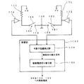
図6には、上記の往復する円運動(振動)を可動子120に生じさせるための制御部のブロック図が示されている。図1、図3および図4では記載が省略されているが、振動装置100におけるコイル104の内側には、図6に示すホールセンサ151が配置され、コイル105の内側には、ホールセンサ152が配置されている。また、振動装置100の外部には、図6に示す制御部153が外付け回路として配置されている。制御部153は、マイコン機能とコイル104,105に駆動電流を流す機能を有している。
(Control part)
FIG. 6 is a block diagram of a control unit for causing the
可動子120が軸ピン107を回転中心として回転すると、ホールセンサ151,152と磁石122〜124の相対位置関係が変化し、ホールセンサ151,152の出力が変化する。このホールセンサ151,152からの出力と可動子120の位置の関係は予め調べられており、その情報は、制御部153の可動子位置検出部154が備えるメモリ中に記憶されている。可動子位置検出部154は、ホールセンサ151,152の出力に基づき、可動子120の角度位置を検出する、また、可動子位置検出部154は、検出した可動子120の角度位置に基づき、どのタイミングでコイル104,105に流す駆動電流の極性を反転させるかを決め、上記の極性の切り替えを制御するための極性切り替え信号を生成し、それを駆動電流切り替え部155に出力する。ホールセンサ151,152の出力と、極性を切替えるタイミングとの関係は、予め行った予備実験の結果に基づき、適切なものが選択され、それは可動子位置検出部154が備えるメモリ中に記憶されている。
When the
駆動電流切り替え部155は、可動子位置検出部154から出力される極性切り替え信号に基づき、コイル104,105に供給している駆動電流の極性を反転させる。この極性の反転が周期的に行われることで、可動子120の往復する回転運動、すなわちストッパ部109と110との間における左回転→右回転→左回転→右回転→・・・が繰り返し発生し、振動が発生する。
The drive current switching unit 155 inverts the polarity of the drive current supplied to the
(優位性)
以上述べたように、図1および図2に示す振動装置100は、ケース本体101に対して軸ピン107によって支えられ、軸ピン107を中心として往復する円運動が可能であり、隣接する部分で極性が異なるように軸ピン107を中心とした円周の方向に並んで配置された複数の磁極N、磁極S、磁極Nを備えた可動子120を備えている。また、振動装置100は、可動子120と隙間を有した状態で対向したコイル104,105とを備えている。ここで、コイル104,105に流れる電流の向きを切替えることで可動子120が軸ピン107を中心とした往復する円運動を行う。
(Superiority)
As described above, the
この構造によれば、可動子120は軸ピン107で支えられ、可動子120は、この軸ピン107を中心として往復する円運動を行い機械的な振動を発生する。この際、可動子120がストッパ部109または110に接触していない状態において、可動子120の動きを規制するのは、軸ピン107に対して回転自在な状態で可動子120を保持するボールベアリング111部分の摩擦抵抗が主であり、振幅の大きさに比例して振動を押さえ込むような力は存在しない。このため、可動子120が可動角度範囲において常に加速され、最も振れた位置、即ち、ストッパ部と接触の際における可動子の速度(回転速度)を大きくでき、大きな加振力が得られる。また、上述したように振動を抑え込む力が存在しないので、駆動に要した投入エネルギー(投入電力)が振動以外に消費される割合が小さく、効率よく振動を生じさせることができる。
According to this structure, the
2.第2の実施形態
図7には、振動装置200が示されている。振動装置200は、磁石122,123,124の上面(コイル104,105に対向した面の反対側の面)に接触してバックヨーク150が取り付けられている。バックヨーク150は、磁性材料で構成された薄板である。バックヨーク150を取り付けることで、可動子120と天板130の間のエアギャップが無くなり、磁気回路の磁気抵抗が削減され、コイルを貫く磁束密度が高くなり、ローレンツ力が大きくなる。また、可動子120の慣性質量が増加し、慣性モーメントが増加するので、強い振動を発生させる上で有利となる。
2. Second Embodiment FIG. 7 shows a
3.第3の実施形態
以下、可動子の位置を検出する手段として、ストッパをスイッチとして用いた構成の一例を説明する。この例は、可動子のストッパへの衝突を契機として、コイルに流す電流の向きを反転させる構成の一例として把握することもできる。図8には、底板103に垂直な方向から見た振動装置200が示されている。図8では、図7の天板130が取り外された状態が示されている。振動装置200は、図1の振動装置100において、ストッパ部材108の部分に可動子120の突起部126の衝突(接触)を検知する仕組みを組み込んだ構造を有している。この部分の構造と駆動制御に係る構成以外の部分は、振動装置200と振動装置100とにおいて同じである。以下、振動装置200の振動装置100と異なる部分について説明する。
3. Third Embodiment Hereinafter, an example of a configuration using a stopper as a switch as means for detecting the position of the mover will be described. This example can also be grasped as an example of a configuration in which the direction of the current flowing through the coil is reversed when the mover collides with the stopper. FIG. 8 shows the
図8に示す振動装置200のストッパ部材108は、スイッチ161と164を備えている。スイッチ161は、電気絶縁性の台座162の上に電気導電性の接触端子163が配置されている部品を有し、ストッパ部109を接触端子163と接触可能な電極として用いる構造を有している。スイッチ164は、電気絶縁性の台座165の上に電気導電性の接触端子166が配置されている部品を有し、ストッパ部110を接触端子166と接触可能な電極として用いる構造を有している。ここで、ストッパ部109,110は、メッキされたバネ鋼により構成され、ケース本体101に電気的に接続されている。また、ケース本体101は、系のアース電位とされている。
The
図8の状態、すなわち突起部126がストッパ部109およびストッパ部110に接触していない状態において、接触端子163とストッパ部109の裏面側とは接触しておらず、また接触端子166とストッパ部110の裏面側とは接触していない。
In the state of FIG. 8, that is, in the state where the
図9に電気的な構成を示す。接触端子163には、検出抵抗171を介してバイアス電圧(+V)が加えられ、接触端子166には、検出抵抗172を介してバイアス電圧(+V)が加えられている。接触端子163がストッパ部109に接触すると、検出抵抗171に電流が流れ、検出抵抗171の両端に発生する電圧が電圧検出器173によって検出される。接触端子166がストッパ部110に接触すると、検出抵抗172に電流が流れ、検出抵抗172の両端に発生する電圧が電圧検出器174によって検出される。可動子位置検出部154は、電圧検出器173と174から出力される電圧検出信号に基づいて、突起部126のストッパ部109または110への接触を検出し、それにより可動子120の角度位置を検出する。その他の制御部153の機能は、図6の場合と同じである。
FIG. 9 shows an electrical configuration. A bias voltage (+ V) is applied to the contact terminal 163 via the detection resistor 171, and a bias voltage (+ V) is applied to the
例えば、可動子120が図8の時計回り方向に回転し(振れて)、突起部126がストッパ部109に接触すると、ストッパ部109が自身の弾性によって接触端子163の側に押されて変形し、ストッパ部109と接触端子163が導通する。この導通が電圧検出器173を介して可動子位置検出部154により検出される。これにより、可動子120がストッパ部109に接触する角度位置にある状態が検出される。この検出を契機として駆動電流切り替え部155がコイル104,105への駆動電流の極性を切り替える。そしてこの駆動電流の切り替えにより、可動子120がストッパ部110の方向に移動の方向を反転させる。
For example, when the
以上説明した図8および図9に示す例は、コイルに流す電流の向きを切替えるスイッチとして、板バネを用いたストッパを利用している。そして、板バネへの可動子の接触を板バネの変形に起因する板バネと接触端子との電気的な接触により検出している。この構造は、部品点数が少なくて済み、構造が簡素であり、低コストで得ることができる。 The examples shown in FIGS. 8 and 9 described above use a stopper using a leaf spring as a switch for switching the direction of the current flowing through the coil. The contact of the movable element to the leaf spring is detected by the electrical contact between the leaf spring and the contact terminal caused by the deformation of the leaf spring. This structure requires a small number of parts, has a simple structure, and can be obtained at low cost.
可動子120の移動方向(回転方向)を切替える手段としては、磁気センサや上述した機械的なスイッチを利用した構成以外に、可動子がストッパに衝突した衝撃を検知する加速度センサや圧電センサを利用したもの、コイル104,105の一方または両方に流れる電流の値の変化を検出し、それを利用したもの等が挙げられる。
As a means for switching the moving direction (rotation direction) of the
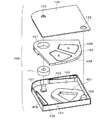
4.第4の実施形態
図10および図11には、振動装置300が示されている。なお、図11では、天板130を取り外した状態が記載されている。振動装置300において、図1に示す振動装置100と同じ符号の部分は、振動装置100と同じである。以下、振動装置300の振動装置100と異なる部分について説明する。振動装置300は、可動子120の軸受部分の構造が図1の振動装置100と異なっている。
4). Fourth Embodiment FIG. 10 and FIG. 11 show a
振動装置300の底板103には、円筒形状のスペーサ302が固定されている。スペーサ302は、その上部に縮径部302aが設けられ、その部分が天板130に設けられたスペーサ固定孔311に嵌る。スペーサ302の周囲の底板103の部分には、可動子120の回転軸を中心とする円環状の溝301が設けられている。円環状の溝301は、円環状に底板103を外側に窪ませた構造を有している。図11(B)には、円環状の溝301が設けられていることで生じた底板103の膨らみ301’が示されている。スペーサ302には、平たい円環状のリテーナ303が緩く嵌め込まれた状態で装着される。リテーナ303は、回転軸を中心とした円周の方向に延在した長孔304が当該円周の方向に沿って複数設けられている。この長孔304のそれぞれには、ベアリングボール305が転がり自在な状態で収容される。ベアリングボール305は、リテーナ303に保持された状態において、円環状の溝301に接触し、そこを転がる。また、可動子120のベアリングボール305が当たる部分には、円環状の溝306と同様な図示されていない円環状の溝が形成されており、この円環状の溝にベアリングボール305は接触し、そこに転がり自在な状態で収容される。
A
可動子120の軸孔121の回りには、回転軸を中心とした円環状の溝306が形成されている。この円環状の溝306に複数のベアリングボール309のそれぞれが接触し、そこに転がり自在な状態で収容される。複数のベアリングボール309は、リテーナ307に回転自在な状態で保持される。リテーナ307は、スペーサ302に緩く嵌め込まれた状態で装着される。リテーナ307には、回転軸を中心とした円周の方向に延在した長孔308が当該円周の方向に沿って複数設けられている。この長孔308それぞれに複数のベアリングボール309のそれぞれが転がり自在な状態で収容される。ベアリングボール309は、天板130の符号310の部分の裏面側に設けられた円環状の溝を転がり自在な状態で、天板130に接触する。また、可動子120の軸孔121の径は、スペーサ302の径よりも大きく、軸孔121の内周は、スペーサ302に接触しない。
Around the
この構造では、ベアリングボール305,309によってスラスト方向の荷重が保持される。こうして、スペーサ302の位置を回転中心とした可動子120の往復する円運動(振動)が許容される構造が実現されている。
In this structure, the load in the thrust direction is held by the bearing
ここで、円環状の溝301、長孔304および可動子120の下面側に設けられた図示されない円環状の溝は、スペーサ302を中心とした円周に沿って延在している。また、円環状の溝306、長孔308、および符号310の部分の裏面側に設けられた円環状の溝もスペーサ302を中心とした円周に沿って延在している。この構造によれば、ベアリングボール305は、円環状の溝301、長孔304および可動子120側の図示されない円環状の溝によってその転がりが束縛され、スペーサ302を中心とした円周の方向にのみ、その転がりが許容されている。同様に、ベアリングボール309は、円環状の溝306、長孔308および符号310の部分の裏面側に設けられた円環状の溝によってその転がりが束縛され、スペーサ302を中心とした円周の方向にのみ、その転がりが許容されている。このベアリングボール305,309の束縛状態により、可動子120は、スペーサ302の中心位置を回転中心とした往復する円運動が可能な状態で底板103および天板130に対して保持されている。
Here, an annular groove (not shown) provided on the lower surface side of the
図10および図11に示す構造は、底板103と天板130でベアリングボールの受けが行われるので、全体の厚みをより薄くすることができ、また部品の数を減らすことができる。なお、円環状の溝306およびそれと反対側の面に形成された図示されていない円環状の溝の代わりに、複数の長溝、つまりスペーサ302を中心とした円周に沿って延在する溝を当該円周に沿って複数設け、そこでベアリングボール305,309を受ける構造も可能である。
In the structure shown in FIGS. 10 and 11, since the bearing balls are received by the
5.第5の実施形態
図12には、振動装置400が示されている。振動装置400において、図1に示す振動装置100と同じ符号の部分は、振動装置100と同じである。以下、振動装置400の振動装置100と異なる部分について説明する。振動装置400は、可動子が備える磁石が2つで、ケース本体(固定子)に備えるコイルが一つである点が図1の振動装置100と異なっている。
5. Fifth Embodiment FIG. 12 shows a
振動装置400は、底板103上にコイル401が固定されている。コイル401の形状は、図1のコイル104および105と概略同じであるが、その周方向における寸法は、コイル104,105よりも大きな寸法とされている。可動子120には、薄型の磁石404,405が嵌め込まれて固定されている。磁石404,405は、周方向で隣接する磁極の極性が反転するように、極性が表裏で反転した状態に着磁されている。
In the
この例において、可動子120は突起部を備えていない。ケース本体101の側板102の可動子120の側部に対向可能な部分には、ストッパ部材402と403が固定されている。ストッパ部材402と403は、板バネを加工して得たもので、回転してきた可動子120が衝突すると、それを逆方向に跳ね返す。この例では、ストッパ部材402,403によって、可動子120の可動範囲を制限するストッパが構成されている。
In this example, the
動作の原理は、図1の振動装置100と同じである。図12に示す振動装置400は、磁石およびコイルの数が少ないので、より小型化および低コスト化が図れる。また、ストッパの位置が可動子120の両サイドにあることも小型化の点で有利となる。
The principle of operation is the same as that of the
6.第6の実施形態
可動子の磁石を1個の多極着磁された磁石により構成することも可能である。以下、この場合の一例を説明する。図13には、振動装置500が示されている。振動装置500は、可動子120における磁石の構造が図1の振動装置100と異なっている。なお、図13には、天板130(図1参照)を取り外した状態が示されている。
6). Sixth Embodiment It is also possible to configure the magnet of the mover with one multipolar magnet. Hereinafter, an example of this case will be described. FIG. 13 shows a
振動装置500では、可動子120に多極着磁された磁石501が取り付けられている。磁石501は、略扇形を有し、回転軸を中心した円周の方向に沿って隣接する磁極の極性が反転するようにNSN(裏面側から見ればSNS)と3極に着磁されている。他の部分の構造および動作原理は、図1の振動装置100と同じである。可動子に配置する磁石を1個の多極着磁された磁石により構成することで、可動子に係る加工コストを低減することができる。この可動子の磁極の構造は、図12の構造に適用することもできる。
In the
7.第7の実施形態
図14には、振動装置600が示されている。振動装置600は、図12の振動装置400において、バネ性を有した板バネにより構成されたストッパ部材402,403の代わりにブロック状のストッパ部材601,602を採用した例である。ブロック状のストッパ部材601,602としては、鋼材等の剛体に近い部材として扱える材料を用いた構成、ゴム等の弾性体としての性質が強く現れる材料を用いた構成、あるいは両者の性質を備えた樹脂等の材料を用いた構成が挙げられる。
7). Seventh Embodiment FIG. 14 shows a
ストッパ部材601,602として、剛体に近い材質のものを利用すると、可動子120の反発が非弾性反発に近くなり、エネルギーの損失が抑えられ、また可動子120の移動の向きの反転に要する時間が極短時間となるので、より大きな振動が得られる。また、可動子120がストッパ部材601,602に衝突する際の衝突音および衝撃感が得られる。
When a material close to a rigid body is used as the
ストッパ部材601,602として、弾性を有する材質のものを利用すると、可動子120の反発が弾性反発に近くなり、振動をソフトなものにチューニングすることができる。また、可動子120がストッパ部材601,602に衝突する際の衝突音の発生を抑えることができる。また、ストッパ部材601,602の材質や構造を調整することで、上述した衝撃音や衝撃感の程度を調整することができる。
If a material having elasticity is used as the
8.第8の実施形態
図1,図7,図10のコイル104,105、および図12のコイル401に流す電流の向きの切り替えを予め定めた周波数で行う構成も可能である。この場合、例えば、予め実験的に可動子120も含めた系の共振周波数を測定しておき、その測定結果に基づいて、可動子120が特定の周波数で振動するようにコイル104,105(またはコイル401)に流す電流の向きの切り替えを行う外付け駆動回路の定数を決めておけばよい。
8). Eighth Embodiment A configuration in which the direction of the current flowing through the
9.第9の実施形態
図15には、振動装置700の分解された状態が示されている。図16には、振動装置700において、天板130を取り外した状態が記載されている。図17には、振動装置700におけるボールを装着した状態の可動子が示されている。図18には、振動装置700を軸に垂直な方向から見た断面の状態が示されている。
9. Ninth Embodiment FIG. 15 shows an exploded state of the
振動装置700において、図10に示す振動装置300と同じ符号の部分は、振動装置300と同じである。以下、振動装置700の振動装置300と異なる部分について説明する。振動装置700は、可動子120の軸受部分の構造が図10の振動装置300と異なっている。
In the
すなわち、振動装置700では、軸ピン701が可動子120に固定されている(あるいは一体に構成された構造とされている)。軸ピン701が対向する底板103の部分には、底板103を円柱状に外側に窪ませた凹部702が設けられている。図16には、この凹部702の外側の部分に当たる底板103から外側に膨らんだ部分702’が示されている。また、軸ピン701が対向する天板130の部分には、天板130を円柱状に外側に窪ませた凹部703(図18参照)が設けられている。図15,図18には、この凹部703の外側の部分に当たる天板130から外側に膨らんだ部分703’が示されている。
That is, in the
軸ピン701の両端部には、それぞれにベアリングボールの保持器として機能する平たい円環状のリテーナ710,720が軸ピン701に対して回転自在な状態で取り付けられている。リテーナ710の円環状の部分には、回転軸を中心とした円周の方向に沿って複数の溝711が形成されており、この溝711のそれぞれには、ベアリングボール712が転がり自在な状態で収容されている。ベアリングボール712を保持したリテーナ710は、その一部が凹部702に収まり、その状態において、軸ピン701の下端部の外周面は、複数のボール712を隔てて底板103に設けられた凹部702内側の円筒面(側面)に支えられる。また、この状態において、ベアリングボール712は、凹部702の底面に接触し、ベアリングボール712があることで、軸ピン701の下端面は、凹部702の底面から少し浮いた状態とされている。ベアリングボール712が転がることで、軸ピン701を軸とした可動子120のケース本体101に対する回転が可能とされている。
Flat
同様に、リテーナ720の円環状の部分には、回転軸を中心とした円周の方向に沿って複数の溝721が形成されており、この溝721のそれぞれには、ベアリングボール722が転がり自在な状態で収容されている。ベアリングボール722を保持したリテーナ720は、その一部が凹部703に収まり、その状態において、軸ピン701の上端部の外周面は、複数のボール722を隔てて天板130に設けられた凹部703内側の円筒面(側面)に支えられる。また、この状態において、ベアリングボール722は、凹部703の上面に接触し、ベアリングボール722があることで、軸ピン701の上端面は、凹部703の上面から少し離れた状態とされている。ベアリングボール722が転がることで、軸ピン701を軸とした可動子120の天板130に対する回転が可能とされている。
Similarly, a plurality of
以上述べたように、振動装置700では、ベアリングボール712を区画するリテーナ710と、底板103に設けられ、リテーナ712の少なくとも一部が納まる凹部702とを備え、可動子120は軸ピン701に固定されており、リテーナ710は、軸ピン701の端部近傍に係止されており、リテーナ710の各区画に配列したベアリングボール712が底板103に設けられた凹部702の内側に転がり可能な状態で接触する。また、ベアリングボール722を区画するリテーナ720と、天板130に設けられ、リテーナ720の少なくとも一部が納まる凹部703とを備え、リテーナ720は、軸ピン701の端部近傍に係止されており、リテーナ720の各区画に配列したベアリングボール722が天板130に設けられた凹部703の内側に転がりが可能な状態で接触する。振動装置300に比べ、振動装置700は、製造と組立が共にし易くなる。但し、可動子120にベアリングボールを納める空間が設けられていないため、底板103と天板130は、その分が外へ膨らむ。
As described above, the
なお、この実施形態において、凹部702は、軸受を構成するベアリングボール712を収容し、更に軸受を構成するリテーナ710の一部を収容する収容領域の一例である。また、凹部703は、軸受を構成するベアリングボール722を収容し、更に軸受を構成するリテーナ720の一部を収容する収容領域の一例である。
In this embodiment, the
10.第10の実施形態
図19には、振動装置800の上面図(A)、(A)におけるA−Aの線で切断した側断面図(B)およびケース本体101の斜視図(C)が示されている。振動装置800は、軸受の部分に特徴がある。軸受以外の部分の構造は、他の実施形態の構造が適用できるので、ここでは説明は省略する。この例においても図15に示す構造の場合と同様に底板103に円柱状に外側に窪ませた凹部702が設けられ、天板130にも円柱状に外側に窪ませた凹部703が設けられている。
10. Tenth Embodiment FIG. 19 shows a top view (A) of the
また、軸ピン801は、可動子120に固定され、軸ピン801の両端部は、角が削られて円錐面802,803とされている。円錐面802の部分は、その少なくとも一部が凹部702の内側に収容され、円錐面802と凹部702の内側の隅の部分との間に複数のベアリングボール804が転がることが可能な状態で保持される。また、円錐面803の部分は、その少なくとも一部が凹部703の内側に収容され、円錐面803と凹部703の内側の隅の部分との間に複数のベアリングボール805が転がることが可能な状態で保持される。また、ベアリングボール804があることで軸ピン801の下端面は、凹部702の底面と接触せず、ベアリングボール805があることで軸ピン801の上端面は、凹部703の上面と接触しない構造とされている。
Further, the
このように、振動装置800は、可動子120に固定された軸ピン801の端部に円錐面802,803が形成されており、底板103には、円錐面802の少なくとも一部が納まる凹部702が設けられ、天板130には、円錐面803の少なくとも一部が納まる凹部703が設けられている。そして、軸ピン801の円錐面802と凹部702の内側とにベアリングボール804が転がる状態で接触し、軸ピン801の円錐面803と凹部703の内側とにベアリングボール805が転がる状態で接触している。この構造では、軸ピン801両端の縁に形成された円錐面802,803を利用して軸ピン801が回転自在な状態で支持される。この構造では、ベアリングボールを保持するためのリテーナ(保持器)を用いないので、部品点数をより少なくでき、また全体の厚みを更に薄くすることができる。
As described above, in the
11.その他
本発明の態様は、上述した個々の実施形態に限定されるものではなく、当業者が想到しうる種々の変形も含むものであり、本発明の効果も上述した内容に限定されない。すなわち、特許請求の範囲に規定された内容およびその均等物から導き出される本発明の概念的な思想と趣旨を逸脱しない範囲で種々の追加、変更および部分的削除が可能である。
11. Others Aspects of the present invention are not limited to the individual embodiments described above, but include various modifications that can be conceived by those skilled in the art, and the effects of the present invention are not limited to the above-described contents. That is, various additions, modifications, and partial deletions can be made without departing from the concept and spirit of the present invention derived from the contents defined in the claims and equivalents thereof.
本発明は、振動装置に利用することができる。 The present invention can be used for a vibration device.
100…振動装置、101…ケース本体(固定子)、102…側板、103…底板、104…コイル、104a…第1の延在部、104b…第2の延在部、104c…外周部、104d…内周部、105a…第1の延在部、105b…第2の延在部、105c…外周部、105d…内周部、105…コイル、106…固定ピン、107…軸ピン、108…ストッパ部材、109…ストッパ部、110…ストッパ部、111…ボールベアリング、120…可動子、121…軸孔、122…磁石、123…磁石、124…磁石、125…掘り下げられた部分、126…突起部、130…天板、131…ピン固定孔、132…ピン固定孔、140…回転軸を中心とした円周の方向、141…磁路、142…磁路、143…磁路、144…磁路、145…ローレンツ力、146…ローレンツ力の反力、150…バックヨーク、161…スイッチ、162…台座、163…接触端子、164…スイッチ、165…台座、166…接触端子、171…検出抵抗、172…検出抵抗、200…振動装置、300…振動装置、301…円環状の溝、302…スペーサ、302a…縮径部、303…リテーナ、304…長孔、305…ベアリングボール、306…円環状の溝、307…リテーナ、308…長孔、309…ベアリングボール、310…裏側面に設けられた円環状の溝、311…スペーサ固定孔、400…振動装置、401…コイル、402…ストッパ部材、403…ストッパ部材、404…磁石、405…磁石、500…振動装置、501…多極着磁された磁石、600…振動装置、601…ブロック状のストッパ部材、602…ブロック状のストッパ部材、700…振動装置、701…軸ピン、702…凹部、702’…外側に膨らんだ部分、703…凹部、703’…外側に膨らんだ部分、710…リテーナ、711…溝、712…ベアリングボール、720…リテーナ、721…溝、722…ベアリングボール、800…振動装置、801…軸ピン、802…円錐面、803…円錐面、804…ベアリングボール、805…ベアリングボール。
DESCRIPTION OF
Claims (7)
前記底板に対して往復する円運動が可能であり、前記円運動の回転軸の中心からずれた位置に重心が設けられ、複数の磁極を備えた可動子と、
前記底板に固定されたコイルと、
前記可動子の前記複数の磁極が生成する磁場と前記コイルに流れる電流との間で作用するローレンツ力により前記可動子の前記往復する円運動が生じ、前記コイルに流れる電流の向きを切替えることにより前記可動子の前記往復する円運動の方向を切替する手段と
を備え、
前記可動子が前記回転軸を中心とした往復する円運動を行うことを特徴とする振動装置。 The bottom plate,
A circular motion that reciprocates with respect to the bottom plate is possible, a center of gravity is provided at a position deviated from the center of the rotational axis of the circular motion,
A coil fixed to the bottom plate;
The reciprocating circular motion of the mover is generated by the Lorentz force acting between the magnetic field generated by the plurality of magnetic poles of the mover and the current flowing through the coil, and the direction of the current flowing through the coil is switched. Means for switching the direction of the reciprocating circular motion of the mover,
The vibrating device according to claim 1, wherein the movable element performs a reciprocating circular motion around the rotation axis.
前記可動子は前記軸を中心として往復する円運動が可能であることを特徴とする請求項1乃至3のいずれか一項に記載の振動装置。 Comprising a shaft fixed to the bottom plate,
4. The vibration device according to claim 1, wherein the movable element is capable of circular motion reciprocating around the axis. 5.
前記底板に対して向かい合わせに配置された天板と
を備え、
前記底板には、前記軸を保持する第1の軸受の少なくとも一部を収容する第1の収容領域が形成され、
前記天板には、前記軸を保持する第2の軸受の少なくとも一部を収容する第2の収容領域が形成され、
前記第1の収容領域に前記第1の軸受の少なくとも一部が収容され、且つ、前記第2の収容領域に前記第2の軸受の少なくとも一部が収容された状態において、前記可動子は前記軸を中心とした往復する円運動が可能であることを特徴とする請求項1乃至3のいずれか一項に記載の振動装置。 A shaft fixed to the mover;
And a top plate arranged facing the bottom plate,
The bottom plate is formed with a first housing region that houses at least a part of the first bearing that holds the shaft,
The top plate is formed with a second housing region that houses at least a part of the second bearing that holds the shaft,
In a state where at least a part of the first bearing is accommodated in the first accommodation area and at least a part of the second bearing is accommodated in the second accommodation area, the mover is The vibration device according to any one of claims 1 to 3, wherein a reciprocating circular motion about an axis is possible.
前記底板および前記可動子に接触し、且つ、前記底板および前記可動子に対して前記回転軸を中心とする円周の方向に転がり、スラスト方向の荷重を保持するベアリングボールと、
前記天板および前記可動子に接触し、且つ、前記天板および前記可動子に対して前記回転軸を中心とする円周の方向に転がり、スラスト方向の荷重を保持するベアリングボールと
を備え、
前記可動子は、前記底板と前記天板の間において、往復する円運動が可能な状態で保持されていることを特徴とする請求項1乃至3のいずれか一項に記載の振動装置。
Comprising a top plate arranged facing the bottom plate,
A bearing ball that contacts the bottom plate and the mover, rolls in a circumferential direction around the rotation axis with respect to the bottom plate and the mover, and holds a load in a thrust direction;
A bearing ball that contacts the top plate and the mover, rolls in a circumferential direction around the rotation axis with respect to the top plate and the mover, and holds a load in a thrust direction;
4. The vibration device according to claim 1, wherein the movable element is held in a state in which a reciprocating circular motion is possible between the bottom plate and the top plate. 5.
Priority Applications (1)
| Application Number | Priority Date | Filing Date | Title |
|---|---|---|---|
| JP2011246499A JP2013103142A (en) | 2011-11-10 | 2011-11-10 | Vibration device |
Applications Claiming Priority (1)
| Application Number | Priority Date | Filing Date | Title |
|---|---|---|---|
| JP2011246499A JP2013103142A (en) | 2011-11-10 | 2011-11-10 | Vibration device |
Publications (1)
| Publication Number | Publication Date |
|---|---|
| JP2013103142A true JP2013103142A (en) | 2013-05-30 |
Family
ID=48623133
Family Applications (1)
| Application Number | Title | Priority Date | Filing Date |
|---|---|---|---|
| JP2011246499A Pending JP2013103142A (en) | 2011-11-10 | 2011-11-10 | Vibration device |
Country Status (1)
| Country | Link |
|---|---|
| JP (1) | JP2013103142A (en) |
Cited By (7)
| Publication number | Priority date | Publication date | Assignee | Title |
|---|---|---|---|---|
| KR20160048047A (en) * | 2016-04-18 | 2016-05-03 | 강소연 | Vibrator |
| CN109155579A (en) * | 2016-05-16 | 2019-01-04 | 日商鹰野株式会社 | rotary solenoid |
| JP2019030855A (en) * | 2017-08-09 | 2019-02-28 | 日本電産セイミツ株式会社 | Vibration motor |
| JP2019512198A (en) * | 2016-02-19 | 2019-05-09 | 胡建坤 | Swing motor and electric clipper |
| JPWO2018051919A1 (en) * | 2016-09-13 | 2019-06-24 | アルプスアルパイン株式会社 | Vibration actuator and electronic device |
| KR102144680B1 (en) * | 2020-04-22 | 2020-08-28 | 자화전자(주) | Actuator for generating vibration |
| RU2790957C1 (en) * | 2021-12-29 | 2023-02-28 | Публичное акционерное общество "Арзамасское научно-производственное предприятие "ТЕМП-АВИА" | Rotary-pendulum inertial element |
-
2011
- 2011-11-10 JP JP2011246499A patent/JP2013103142A/en active Pending
Cited By (10)
| Publication number | Priority date | Publication date | Assignee | Title |
|---|---|---|---|---|
| JP2019512198A (en) * | 2016-02-19 | 2019-05-09 | 胡建坤 | Swing motor and electric clipper |
| KR20160048047A (en) * | 2016-04-18 | 2016-05-03 | 강소연 | Vibrator |
| KR101632937B1 (en) | 2016-04-18 | 2016-06-23 | 강소연 | Vibrator |
| CN109155579A (en) * | 2016-05-16 | 2019-01-04 | 日商鹰野株式会社 | rotary solenoid |
| JPWO2018051919A1 (en) * | 2016-09-13 | 2019-06-24 | アルプスアルパイン株式会社 | Vibration actuator and electronic device |
| JP2019030855A (en) * | 2017-08-09 | 2019-02-28 | 日本電産セイミツ株式会社 | Vibration motor |
| KR102144680B1 (en) * | 2020-04-22 | 2020-08-28 | 자화전자(주) | Actuator for generating vibration |
| WO2021215628A1 (en) * | 2020-04-22 | 2021-10-28 | 자화전자 주식회사 | Actuator for generating vibration |
| US12040684B2 (en) | 2020-04-22 | 2024-07-16 | Jahwa Electronics Co., Ltd. | Actuator for generating vibration |
| RU2790957C1 (en) * | 2021-12-29 | 2023-02-28 | Публичное акционерное общество "Арзамасское научно-производственное предприятие "ТЕМП-АВИА" | Rotary-pendulum inertial element |
Similar Documents
| Publication | Publication Date | Title |
|---|---|---|
| US8797152B2 (en) | Haptic actuator apparatuses and methods thereof | |
| AU2016100269A4 (en) | Linear actuator | |
| JP2013103142A (en) | Vibration device | |
| JP7248387B2 (en) | Vibration actuators and electronics | |
| US10994304B2 (en) | Vibration device, wearable terminal and incoming call notification device | |
| JP2015144048A (en) | rotary input device | |
| JP2015095943A (en) | Vibration actuator and portable information terminal | |
| US20190207499A1 (en) | Vibration actuator and electronic device | |
| WO2010026709A1 (en) | Vibration motor and portable terminal device using same | |
| KR101094651B1 (en) | Sensory signal output apparatus | |
| US11949310B2 (en) | Vibration actuator with movable body with tip part of the core oscillating and a shaft part supporting the movable body on a side of a base | |
| US20190207501A1 (en) | Mover, vibration actuator, and electronic device | |
| JP2015157277A (en) | vibration actuator | |
| JP2015157276A (en) | vibration actuator | |
| JP2017212793A (en) | Linear vibration motor | |
| WO2018008280A1 (en) | Linear vibration motor | |
| JP6378127B2 (en) | Linear vibration motor | |
| JP2007166450A (en) | Portable device and input method of portable device | |
| JP2010063977A (en) | Vibration motor and portable terminal device using the same | |
| US12101011B2 (en) | Electromagnetic actuator | |
| JP2015047525A (en) | Vibration generator | |
| JP7540272B2 (en) | Vibration actuator and electronic device | |
| JP2005348469A (en) | Linear oscillator | |
| JP2013247810A (en) | Vibration actuator | |
| US20220103052A1 (en) | Vibration actuator and electronic apparatus |