JP2013090761A - Stereoscopic endoscope apparatus - Google Patents
Stereoscopic endoscope apparatus Download PDFInfo
- Publication number
- JP2013090761A JP2013090761A JP2011234343A JP2011234343A JP2013090761A JP 2013090761 A JP2013090761 A JP 2013090761A JP 2011234343 A JP2011234343 A JP 2011234343A JP 2011234343 A JP2011234343 A JP 2011234343A JP 2013090761 A JP2013090761 A JP 2013090761A
- Authority
- JP
- Japan
- Prior art keywords
- members
- insertion members
- stereoscopic endoscope
- insertion member
- endoscope apparatus
- Prior art date
- Legal status (The legal status is an assumption and is not a legal conclusion. Google has not performed a legal analysis and makes no representation as to the accuracy of the status listed.)
- Pending
Links
Images


Classifications
-
- A—HUMAN NECESSITIES
- A61—MEDICAL OR VETERINARY SCIENCE; HYGIENE
- A61B—DIAGNOSIS; SURGERY; IDENTIFICATION
- A61B1/00—Instruments for performing medical examinations of the interior of cavities or tubes of the body by visual or photographical inspection, e.g. endoscopes; Illuminating arrangements therefor
- A61B1/00147—Holding or positioning arrangements
-
- A—HUMAN NECESSITIES
- A61—MEDICAL OR VETERINARY SCIENCE; HYGIENE
- A61B—DIAGNOSIS; SURGERY; IDENTIFICATION
- A61B1/00—Instruments for performing medical examinations of the interior of cavities or tubes of the body by visual or photographical inspection, e.g. endoscopes; Illuminating arrangements therefor
- A61B1/00163—Optical arrangements
- A61B1/00193—Optical arrangements adapted for stereoscopic vision
-
- A—HUMAN NECESSITIES
- A61—MEDICAL OR VETERINARY SCIENCE; HYGIENE
- A61B—DIAGNOSIS; SURGERY; IDENTIFICATION
- A61B1/00—Instruments for performing medical examinations of the interior of cavities or tubes of the body by visual or photographical inspection, e.g. endoscopes; Illuminating arrangements therefor
- A61B1/233—Instruments for performing medical examinations of the interior of cavities or tubes of the body by visual or photographical inspection, e.g. endoscopes; Illuminating arrangements therefor for the nose, i.e. nasoscopes, e.g. testing of patency of Eustachian tubes
Abstract
Description
本発明は、立体視内視鏡装置に関する。 The present invention relates to a stereoscopic endoscope apparatus.
下垂体領域に対する外科治療は、経蝶形骨洞到達法の開発により低侵襲で、安全性の高い治療として確立されてきた。従来、この手術法は開頭術において用いられる手術用顕微鏡を用いて行われてきたが、近年、顕微鏡の欠点(視野角が狭い)を補うために内視鏡による下垂体手術が発達している。顕微鏡は、通常の手術手技が応用でき、立体視が可能であるものの、視野角が狭く、術野近傍で死角が多く、さらに対物レンズと術野との距離が大きいという問題がある。一方、内視鏡手術は、視野角が広く、死角が少なく、しかも術野に近接しているために画像が鮮明であるという利点がある。内視鏡手術は今後発展が予想される手術法であるが、立体視が出来ないという短所を有している。これに対して、例えば、特許文献1、2では、2台のカメラあるいは2本の内視鏡を、視差角を生ずる角度で設置し、2つの光軸の視差を利用して3D立体画像が得られる内視鏡が提案されている。さらに、近年、2本の光軸を1本の内視鏡内に収めた3D立体内視鏡も開発されている。
Surgical treatment for the pituitary region has been established as a highly safe treatment with minimal invasiveness by developing a transsphenoidal sinus approach. Conventionally, this surgical method has been performed using a surgical microscope used in craniotomy, but in recent years, pituitary surgery using an endoscope has been developed to compensate for the drawbacks of the microscope (the viewing angle is narrow). . Although the microscope can be applied with a normal surgical technique and can be stereoscopically viewed, there are problems that the viewing angle is narrow, the blind spot is large near the surgical field, and the distance between the objective lens and the surgical field is large. On the other hand, endoscopic surgery has an advantage that the image is clear because the viewing angle is wide, the blind spot is small, and it is close to the surgical field. Endoscopic surgery is a surgical method that is expected to develop in the future, but has the disadvantage that stereoscopic viewing is not possible. On the other hand, for example, in
しかしながら、2本の内視鏡によって立体視を行うためには、それぞれの内視鏡の視差角および焦点を正確に合わせる必要がある。そのため、体外であらかじめ一定の角度を調整して固定するか調整できる装置を付ける必要があり、実際に体内において使用できるものではなかった。これに対して、上記のように1本の内視鏡内に2本の光軸を持った3D立体内視鏡を用いれば、角度の調整などが不要になるが、3D立体画像を得るためには2本の光軸の視差が必要なことから、相当な太さとなり、経鼻内視鏡のように細い鼻孔を通すものには不向きであった。 However, in order to perform stereoscopic viewing with two endoscopes, it is necessary to accurately adjust the parallax angle and the focus of each endoscope. Therefore, it is necessary to attach a device that can be fixed or adjusted by adjusting a certain angle in advance outside the body, and cannot actually be used in the body. On the other hand, if a 3D stereoscopic endoscope having two optical axes in one endoscope is used as described above, angle adjustment and the like are unnecessary, but a 3D stereoscopic image is obtained. Since the parallax of the two optical axes is necessary, the thickness is considerable, and it is unsuitable for a device that passes a thin nostril such as a transnasal endoscope.
本発明は、上記問題を解決するためになされたものであり、鼻孔内への挿入が可能で、取り扱いが容易な立体内視鏡装置を提供することを目的とする。 The present invention has been made to solve the above problems, and an object of the present invention is to provide a stereoscopic endoscope apparatus that can be inserted into a nostril and is easy to handle.
本発明は、鼻孔から挿入して用いられ、頭部内を撮影する立体内視鏡装置であって、第1の挿入部材と、第2の挿入部材と、前記第1の挿入部材の一端部に対物レンズが設けられた第1の光学系と、前記第2の挿入部材の一端部に対物レンズが設けられた第2の光学系と、前記第1及び第2の挿入部材の一端部同士を取り外し可能に連結する連結手段と、を備えている。 The present invention is a stereoscopic endoscope apparatus that is used by being inserted from a nostril and photographs the inside of a head, and includes a first insertion member, a second insertion member, and one end portion of the first insertion member. A first optical system in which an objective lens is provided, a second optical system in which an objective lens is provided at one end of the second insertion member, and one end portions of the first and second insertion members. And a connecting means for removably connecting.
この構成によれば、第1及び第2の挿入部材の一端部を着脱自在に連結する連結手段を有しているため、例えば、下垂体外科手術を行う際に、第1及び第2の挿入部材をそれぞれ鼻孔に挿入した後に、鼻孔内で両者を連結手段により連結することができる。このとき、各挿入部材には、対物レンズを備えた光学系が一つずつ設けられているため、挿入部材の太さを小さくすることができる。これにより、内径が小さい鼻孔にも容易に挿入することができる。このように、本発明においては、鼻孔内に光学系を有する2つの挿入部材を挿入し、内部で連結するため、各光学系の視差による立体画像を形成することができる。その結果、外科手術を効果的に行うことができる。 According to this structure, since it has the connection means which connects the one end part of the 1st and 2nd insertion member so that attachment or detachment is possible, for example, when performing pituitary surgery, the 1st and 2nd insertion After each member is inserted into the nostril, both can be connected by connecting means in the nostril. At this time, since each insertion member is provided with one optical system including an objective lens, the thickness of the insertion member can be reduced. Thereby, it can insert easily also in a nostril with a small internal diameter. In this way, in the present invention, two insertion members having an optical system are inserted into the nostril and connected inside, so that a three-dimensional image based on the parallax of each optical system can be formed. As a result, surgery can be performed effectively.
上記連結手段は、第1及び第2の挿入部材のなす角を変更可能に構成することができる。これにより、鼻孔の大きさや形状の相違に対応することができる。 The connecting means can be configured to change the angle formed by the first and second insertion members. Thereby, it can respond to the difference in the magnitude | size and shape of a nostril.
上記立体内視鏡装置において、第1及び第2の挿入部材の他端部同士を、所定の角度に保持するように互いに固定する固定手段をさらに設けることができる。このような固定手段を設けると、鼻孔の内部で連結手段によって連結した両挿入部材を、鼻孔の外部でも固定することができるため、両者を一体的に保持することができる。したがって、両挿入部材を適切な視差角で固定でき、内視鏡としての取り扱いが容易になる。 The stereoscopic endoscope apparatus may further include a fixing unit that fixes the other end portions of the first and second insertion members to each other so as to be held at a predetermined angle. If such a fixing means is provided, since both the insertion members connected by the connecting means inside the nostril can be fixed also outside the nostril, both can be held integrally. Therefore, both insertion members can be fixed at an appropriate parallax angle, and handling as an endoscope becomes easy.
上記連結手段は、種々の構成にすることができるが、例えば、第1及び第2の挿入部材を磁力によって接続可能に構成することができる。この構成により、両挿入部材を容易に連結することができる。特に、下垂体外科手術を行う際に、第1及び第2の挿入部材をそれぞれ鼻孔に挿入すると、挿入部材の先端が見えないため、両者を正確に連結するのが難しいが、上記のように、両挿入部材を磁力により連結するように構成すると、両者が近接したときに磁力によって引き合って連結させることができるため、挿入部材の一端部が視認し難い場合でも、これらを簡単に連結することができる。磁力による連結を行うには、連結手段において、第1及び第2の挿入部材側の少なくとも一方にマグネットを設ければよい。 Although the said connection means can be made into various structures, it can be comprised so that a 1st and 2nd insertion member can be connected by magnetic force, for example. With this configuration, both insertion members can be easily connected. In particular, when performing pituitary surgery, if the first and second insertion members are respectively inserted into the nostrils, it is difficult to accurately connect the two because the tip of the insertion member is not visible. If both insertion members are connected by magnetic force, they can be attracted and connected by magnetic force when they are close to each other, so even if one end of the insertion member is difficult to see, they can be connected easily Can do. In order to perform connection by magnetic force, a magnet may be provided on at least one of the first and second insertion member sides in the connection means.
また、上記連結手段は、第1及び第2挿入部材側の一方に、他方の挿入部材に対して凸の円弧状の当接面を有するように構成することができる。この構成によれば、両挿入部材が円弧状の当接面を介して連結するため、両挿入部材がなす角度を自由に変更することができる。 Moreover, the said connection means can be comprised so that it may have a convex arc-shaped contact surface with respect to the other insertion member in one side of the 1st and 2nd insertion member side. According to this configuration, since both the insertion members are connected via the arc-shaped contact surface, the angle formed by both the insertion members can be freely changed.
本発明に係る立体内視鏡装置によれば、鼻孔内への挿入が可能で、取り扱いを容易に行うことができる。 The stereoscopic endoscope apparatus according to the present invention can be inserted into the nostril and can be easily handled.
以下、本発明に係る立体視内視鏡装置の一実施形態について図面を参照しつつ説明する。図1はこの立体視内視鏡装置の概略構成図である。なお、以下の説明における軸方向及び径方向は、各挿入部材の軸方向、及びこれに垂直な径方向を示している。 Hereinafter, an embodiment of a stereoscopic endoscope apparatus according to the present invention will be described with reference to the drawings. FIG. 1 is a schematic configuration diagram of this stereoscopic endoscope apparatus. In addition, the axial direction and radial direction in the following description have shown the axial direction of each insertion member, and the radial direction perpendicular | vertical to this.
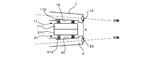
図1に示すように、本実施形態に係る立体視内視鏡装置は、下垂体領域に対する外科治療に用いられるものであり、鼻孔から挿入されて、体内の立体画像を撮影するものである。具体的には、棒状に形成されて各鼻孔内に挿入される一対の挿入部材、つまり第1挿入部材1及び第2挿入部材2を備えており、これらは硬性鏡によって構成されている。また、各挿入部材1,2の先端には、両者を取り外し可能に連結する連結部材11,21がそれぞれ設けられている。一方、各挿入部材1,2の後端側には、各挿入部材1,2を所定の角度に保持する固定部材3が設けられている。また、各挿入部材1,2には、光源装置4から供給される照明光を伝送し、被写体に照射光を照射するライトガイド14,24が内蔵されている。光源装置4としては、発光ダイオードなどを発光素子とし、これを直接変調したものや、あるいは音響光学素子などの外部変調素子によって発光素子の出力光を変調したものを使用することができる。ライトガイド14,24は、例えば、入力光に対して高い透過率を示す材料を用いることができ、複数の微細なプラスチックやガラス製のファイバ束によって形成されるイメージファイバを用いることができる。
As shown in FIG. 1, the stereoscopic endoscope apparatus according to the present embodiment is used for a surgical treatment on a pituitary region, and is inserted through a nostril to take a stereoscopic image inside the body. Specifically, a pair of insertion members formed in a rod shape and inserted into each nostril, that is, a
また、各挿入部材1,2には、撮影用の光学系が内蔵されている。この光学系は、挿入部材1,2の先端に設けられた対物レンズ13,23と、この対物レンズ13,23で結像された被写体の結像画像を伝達するイメージガイド12,22と、を備えている。イメージガイド12,22は、ライトガイド14,24と同様にイメージファイバで構成することができる。そして、各挿入部材1,2の後端部には、TVカメラヘッド15,25が装着されており、各TVカメラヘッド15,25は、信号ケーブル16,26を介して三次元カメラコントロールユニット5に接続されている。また、この三次元カメラコントロールユニット5にはモニタ6が接続されている。この構成により、対物レンズにより結像された被写体の像は、イメージガイド12,22を介してTVカメラヘッド15,25で撮影される。そして、TVカメラヘッド15,25で撮影された視差を有する被写体の画像信号は、三次元カメラコントロールユニット5で信号処理され、モニタ6において立体感のある三次元画像として表示される。
Each of the
次に、連結部材11,21について、図2を参照しつつ説明する。図2は連結部材11,21の拡大平面図である。同図に示すように、各挿入部材1,2の先端の側面には、凹部10、20が形成されており、各連結部材11,21は、矩形状のマグネット111,211、及びこのマグネット111,211と挿入部材1,2の凹部10、20との間で両者を連結する複数のバネ112,212で構成されている。そして、各挿入部材1,2はマグネット111,211が互いに接着されることで、互いの先端が連結される。このとき、マグネット111,211はバネ112,212を介して挿入部材1,2に取り付けられているため、両挿入部材1,2は連結されたままで、角度を自由に変更することができる。このとき、両挿入部材1,2における対物レンズ13,23間の距離Xを、5〜15mmとすることが好ましく、少なくとも8〜10mmとすることがさらに好ましい。なお、マグネット111,211と挿入部材1,2との連結は、上記のようなバネ112,212以外に、ゴムなどの弾性部材を用いることもできる。
Next, the connecting
一方、鼻孔の外部には、両挿入部材1,2を固定する固定部材3が取り付けられている。この固定部材3は、挿入部材1,2が所望の角度になったときに取り付けられて、その角度を保持したまま、両挿入部材1,2を固定するものとすることができる。あるいは、特開平5−341206号公報に開示されているように、例えば、両挿入部材1,2を固定した状態で、その角度を自由に変更するような機構を設けることもできる。なお、上述した連結部材11,21と、固定部3のとの距離は、少なくとも65mm以上離れていることが好ましい。
On the other hand, a fixing member 3 for fixing both the
次に、上記のように構成された立体内視鏡装置の使用方法について説明する。まず、公知の方法で、鼻中隔の一部を切除し、両鼻腔を連通させる。次に、各挿入部材1,2のライトガイド14,24に、光源装置4から照射光を伝達する。次に、第1挿入部材1を一方の鼻孔から挿入し、先端を連通した鼻腔内に配置する。続いて、第2挿入部材2を他方の鼻孔から挿入し、既に鼻腔内にある第1挿入部材1の連結部材11と、第2挿入部材2の連結部材21とを連結する。このとき、両連結部材11,21は、マグネット111,211によって互いに引き合って連結される。続いて、両挿入部材1,2のなす角度を調整し、各光学系の光軸の交点が被写体上に配置されるようにする。これに続いて、鼻孔外で両挿入部材1,2を固定部材3によって固定し、両者1,2を一体的に保持する。この状態で、各挿入部材1,2からは被写体に対して照射光が照射され、両挿入部材1,2の光学系で得られた視差のある被写体の像が、TVカメラヘッド15,25で撮影される。そして、その画像は三次元カメラコントロールユニット5で信号処理され、モニタ6に表示される。これにより、術者は被写体を立体視することができ、これに基づいて、手術を行うことができる。
Next, a method of using the stereoscopic endoscope device configured as described above will be described. First, a part of the nasal septum is excised and the two nasal cavities are communicated by a known method. Next, the irradiation light is transmitted from the light source device 4 to the light guides 14 and 24 of the
以上のように、本実施形態によれば、2つの挿入部材1,2の先端部を着脱自在に連結し、且つ両者のなす角度を調整することができる連結部材11,21を有しているため、下垂体外科手術を行う際に、各挿入部材1,2をそれぞれ鼻孔に挿入した後に、鼻孔内で両者を連結部材11,21により連結することができる。このとき、各挿入部材1,2には、対物レンズ13,23を備えた光学系が一つずつ設けられているため、挿入部材1,2の太さを小さくすることができる。これにより、内径が小さい鼻孔にも容易に挿入することができる。さらに、両挿入部材1,2は、連結部材11,21によって所定の角度で連結できることから、各光学系の視差による立体画像を形成することができ、外科手術を効果的に行うことができる。
As described above, according to the present embodiment, the connecting
以上、本発明の一実施形態について説明したが、本発明はこれに限定されるものではなく、その趣旨を逸脱しない限りにおいて種々の変更が可能である。例えば、上記実施形態では、挿入部材1,2は、上述したものに限定されるものではなく、公知の硬性鏡を用いることができる。すなわち、被写体を撮影可能な対物レンズを有する光学系が内蔵されているものであれば、特には限定されない。また、上記実施形態では、各挿入部材1,2の後端部の途中からライトガイド14,24と光源装置4とを接続しているが、ライトガイド14,24を各TVカメラヘッド15,25まで延長し、ここから光源装置4に接続することもできる。
As mentioned above, although one Embodiment of this invention was described, this invention is not limited to this, A various change is possible unless it deviates from the meaning. For example, in the said embodiment, the
また、上記実施形態では、連結部材11,21を用いて両挿入部材1,2を連結しているが、これに限定されず、挿入部材1,2の一端部同士を取り外し可能に連結できる連結手段であれば、特には限定されない。例えば、両挿入部材1,2を連結する連結手段としては、上記実施形態以外に図3から図6に示すように構成することができる。
Moreover, in the said embodiment, although both the
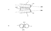
図3に示す例では、第1挿入部材1の先端側面に、金属製の凸部材113を取り付けている。この凸部材113には、径方向外方に凸で、且つ軸方向に延びる円弧状の当接面1131が形成されている。一方、第2挿入部材2の先端側面には、軸方向に延びる平面視矩形状の受け部材213が設けられており、その周囲を囲むように周縁部材214が配置されている。この周縁部材214は、プラスチック等の非金属製またはアルミニウムなどの材料で形成することが好ましい。そして、受け部材213にはマグネットが内蔵されている。また、周縁部材214は、受け部材213よりも径方向外方へ突出しており、周縁部材214に対して受け部材213が凹をなすように構成されている。受け部材213の平面視の大きさは、凸部材113よりもやや大きくなっており、後述するように、周縁部材214の内部に凸部材113が嵌まるようになっている。
In the example shown in FIG. 3, a metal
上記のような構成により、両挿入部材1,2を近接させると、凸部材113が受け部材213のマグネットにより引きつけられ、両者が連結される。このとき、凸部材113は周縁部材214の内部にはまり込むため、第1挿入部材1は軸方向及び径方向の動きが規制される。また、周縁部材214を非金属材料で構成すると、凸部材113は周縁部材214に引きつけられることなく、スムーズに受け部材213と連結される。そして、凸部材113には円弧状の当接面1131が形成されているため、この円弧に沿って、両挿入部材1,2は角度を変更可能となっている。なお、マグネットは、受け部材213または凸部材113の少なくとも一方に配置されていればよい。また、受け部材213と周縁部材214とを金属材料または非金属材料で一体的に形成することもできる。非金属材料で形成する場合には、受け部材213の内部にマグネットや金属材料を埋め込むことで、凸部材113との連結が可能となる。
With the above-described configuration, when both the
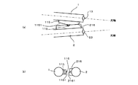
続いて、図4の例について説明する。この例では、第2挿入部材2の先端側面に、断面円弧状の凹面2151を有する受け部材215を取り付けている。凹面2151は、第1挿入部材1の外周面に対応した形状をなしており、径方向内方に凸の円弧状に形成されている。また、受け部材215にはマグネットが内蔵されており、金属製の第1挿入部材1の外周面と連結可能となっている。そして、受け部材215の凹面2151は、第1挿入部材1と第2挿入部材2とが所定の角度をなすように、軸方向に傾斜している。この角度は適宜変更できる。このような構成により、両挿入部材1,2を近接させると、第1挿入部材1が受け部材215のマグネットにより引きつけられ、両挿入部材1,2が連結される。このとき、連結部材215には、上述した凹面2151が形成されているため、第1挿入部材1は軸方向には移動可能であるが、径方向の移動は規制される。また、マグネットによる連結であるため、各挿入部材1,2の後端部側で角度を調節すると、若干の調整であれば、第1挿入部材1が第2挿入部材2に対して角度を変更しつつ、連結状態を保持することができる。なお、第1挿入部材1の外周面が金属で形成されない場合には、第1挿入部材1の外周面に、例えば、金属製のプレートなどを配置すればよい。
Subsequently, the example of FIG. 4 will be described. In this example, a receiving
次に、図5の例について説明する。図5に示す例では、第1挿入部材1の先端側面に、金属製の凸部材115を取り付けている。この凸部材115には、径方向外方に凸で、且つ軸方向に延びる円弧状の当接面1151が形成されている。さらに、当接面1151の中央には、径方向外方に突出する円形状の突起116が形成されている。一方、第2挿入部材2の先端側面には、軸方向に延びる平面視矩形状の受け部材216が設けられており、径方向外方の平坦面の中央には、上述した突起116を受ける凹部2161が形成されている。また、受け部材216には凹部2161の近傍にマグネットが内蔵されている。このような構成により、両挿入部材1,2を近接させると、凸部材115が受け部材216のマグネットにより引きつけられ、両者が連結される。このとき、凸部材115の突起116が受け部材216の凹部2161に嵌まり込むため、第1挿入部材1は軸方向及び径方向の動きが規制される。また、凸部材115には円弧状の当接面1151が形成されているため、この円弧に沿って、両挿入部材1,2は角度を変更可能となっている。
Next, the example of FIG. 5 will be described. In the example shown in FIG. 5, a metal
続いて、図6の例について説明する。図6に示す例では、第1挿入部材1の先端側面に、板状の連結部材117が固定されている。この連結部材117は、径方向に突出する延長片1171と、この延長片1171の先端から軸方向の後端側へ延びる係止片1172とで側面視L字型に形成されており、例えば、金属などで形成することにより、撓むようになっている。一方、第2挿入部材2の先端側面には、軸方向に延びる平面視矩形状の受け部材217が設けられており、先端面には、上述した連結部材117の係止片1172を受け入れる凹部2171が形成されている。このような構成により、両挿入部材1,2を近接させ、連結部材117の係止片1172を受け部材の凹部2171に嵌め込むことで、両挿入部材1,2を連結することができる。これにより、第1挿入部材1は軸方向及び径方向の動きが規制される。また、連結部材117は、板状に形成され、且つ上記のように撓むため、両挿入部材1,2の角度を調整することが可能である。したがって、第1挿入部材1が第2挿入部材2に対して角度を変更しつつ、連結状態を保持することができる。なお、上述した各例の連結手段では、両挿入部材1,2の先端の間の距離がほぼ一定となるため、立体映像を形成するのに適している。
Subsequently, the example of FIG. 6 will be described. In the example shown in FIG. 6, a plate-like connecting
次に、図1で示した固定部材3の他の例について説明する。上記実施形態では、各挿入部材1,2の後端部の途中に固定部材3を取り付けているが、各TVカメラヘッド15,25に固定部材を取り付けることもできる。例えば、図7に示すように、第2挿入部材2側のTVカメラヘッド25に円弧状に形成された固定プレート8を取り付け、第1挿入部材1側に延びるように配置する。一方、第1挿入部材1のTVカメラヘッド15の側端面には、固定プレート8が嵌まるような円弧状の溝151を形成しておく。こうして、固定プレート8を溝151に沿って移動させると、両TVカメラヘッド15,25を近接離間させることができるとともに、両者の角度を調整することができる。そして、図示を省略するが、公知の方法で固定プレート8を溝151に固定すれば、両TVカメラヘッド15,25間の距離を固定することができる。なお、固定プレート8及び溝151を設ける位置は、特には限定されず、例えば、溝の代わりにTVカメラヘッド15の側面に、固定プレート8の挿入穴を形成することもできる。
Next, another example of the fixing member 3 shown in FIG. 1 will be described. In the above embodiment, the fixing member 3 is attached in the middle of the rear end of each of the
1 第1挿入部材
11 対物レンズ(第1の光学系)
113、115 凸部材(固定手段)
117 連結部材(固定手段)
12 イメージガイド(第1の光学系)
13 連結部材(連結手段)
151 溝(固定手段)
2 第2挿入部材
21 対物レンズ(第2の光学系)
213,215,216,217 受け部材(固定手段)
22 イメージガイド(第2の光学系)
23 連結部材(連結手段)
3 固定部材(固定手段)
8 固定プレート(固定手段)
DESCRIPTION OF
113, 115 Convex member (fixing means)
117 connecting member (fixing means)
12 Image guide (first optical system)
13 Connecting member (connecting means)
151 groove (fixing means)
2
213, 215, 216, 217 receiving member (fixing means)
22 Image guide (second optical system)
23 Connecting member (connecting means)
3 Fixing member (fixing means)
8 Fixing plate (fixing means)
Claims (5)
棒状に形成された第1の挿入部材と、
棒状に形成された第2の挿入部材と、
前記第1の挿入部材の一端部に対物レンズが設けられた第1の光学系と、
前記第2の挿入部材の一端部に対物レンズが設けられた第2の光学系と、
前記第1及び第2の挿入部材の一端部同士を取り外し可能に連結する連結手段と、
を備えている、立体内視鏡装置。 A stereoscopic endoscope device that is used by being inserted through a nostril, and photographs the inside of the head,
A first insertion member formed in a rod shape;
A second insertion member formed in a rod shape;
A first optical system in which an objective lens is provided at one end of the first insertion member;
A second optical system in which an objective lens is provided at one end of the second insertion member;
Connecting means for detachably connecting one end portions of the first and second insertion members;
A stereoscopic endoscope apparatus comprising:
The three-dimensional internal view according to any one of claims 1 to 4, wherein the connecting means has a circular arc-shaped contact surface that is convex with respect to the other insertion member on one side of the first and second insertion members. Mirror device.
Priority Applications (2)
| Application Number | Priority Date | Filing Date | Title |
|---|---|---|---|
| JP2011234343A JP2013090761A (en) | 2011-10-25 | 2011-10-25 | Stereoscopic endoscope apparatus |
| PCT/JP2012/076417 WO2013061804A1 (en) | 2011-10-25 | 2012-10-12 | Stereoscopic endoscope apparatus |
Applications Claiming Priority (1)
| Application Number | Priority Date | Filing Date | Title |
|---|---|---|---|
| JP2011234343A JP2013090761A (en) | 2011-10-25 | 2011-10-25 | Stereoscopic endoscope apparatus |
Publications (1)
| Publication Number | Publication Date |
|---|---|
| JP2013090761A true JP2013090761A (en) | 2013-05-16 |
Family
ID=48167637
Family Applications (1)
| Application Number | Title | Priority Date | Filing Date |
|---|---|---|---|
| JP2011234343A Pending JP2013090761A (en) | 2011-10-25 | 2011-10-25 | Stereoscopic endoscope apparatus |
Country Status (2)
| Country | Link |
|---|---|
| JP (1) | JP2013090761A (en) |
| WO (1) | WO2013061804A1 (en) |
Cited By (3)
| Publication number | Priority date | Publication date | Assignee | Title |
|---|---|---|---|---|
| WO2016056100A1 (en) * | 2014-10-09 | 2016-04-14 | オリンパス株式会社 | Medical system |
| JP2020079799A (en) * | 2015-05-18 | 2020-05-28 | コーセプト セラピューティクス, インコーポレイテッド | Method for diagnosing and evaluating treatment of cushing's syndrome |
| JP2021511093A (en) * | 2017-11-30 | 2021-05-06 | シー・アール・バード・インコーポレーテッドC R Bard Incorporated | Intravascular device |
Families Citing this family (1)
| Publication number | Priority date | Publication date | Assignee | Title |
|---|---|---|---|---|
| CN109219382B (en) * | 2016-03-31 | 2021-08-13 | 学校法人庆应义塾 | Endoscope holder |
Family Cites Families (2)
| Publication number | Priority date | Publication date | Assignee | Title |
|---|---|---|---|---|
| JPS5142227Y2 (en) * | 1974-03-28 | 1976-10-14 | ||
| JPS5146994B2 (en) * | 1974-03-28 | 1976-12-11 |
-
2011
- 2011-10-25 JP JP2011234343A patent/JP2013090761A/en active Pending
-
2012
- 2012-10-12 WO PCT/JP2012/076417 patent/WO2013061804A1/en active Application Filing
Cited By (6)
| Publication number | Priority date | Publication date | Assignee | Title |
|---|---|---|---|---|
| WO2016056100A1 (en) * | 2014-10-09 | 2016-04-14 | オリンパス株式会社 | Medical system |
| US20170165455A1 (en) * | 2014-10-09 | 2017-06-15 | Olympus Corporation | Medical system |
| JPWO2016056100A1 (en) * | 2014-10-09 | 2017-08-31 | オリンパス株式会社 | Medical system |
| JP2020079799A (en) * | 2015-05-18 | 2020-05-28 | コーセプト セラピューティクス, インコーポレイテッド | Method for diagnosing and evaluating treatment of cushing's syndrome |
| US11268145B2 (en) | 2015-05-18 | 2022-03-08 | Corcept Therapeutics, Inc. | Methods for treating Cushing's syndrome |
| JP2021511093A (en) * | 2017-11-30 | 2021-05-06 | シー・アール・バード・インコーポレーテッドC R Bard Incorporated | Intravascular device |
Also Published As
| Publication number | Publication date |
|---|---|
| WO2013061804A1 (en) | 2013-05-02 |
Similar Documents
| Publication | Publication Date | Title |
|---|---|---|
| JP4887907B2 (en) | Video display device | |
| EP2872026B1 (en) | Stereo endoscope system | |
| JP5212901B2 (en) | Glasses-type image display device | |
| JP4093503B2 (en) | Stereoscopic endoscope | |
| JPWO2006038662A1 (en) | Image display device and electronic glasses | |
| WO2013061804A1 (en) | Stereoscopic endoscope apparatus | |
| CA2901739C (en) | Endoscope with pupil expander | |
| JP2000010022A (en) | Top structure for stereoscopic endoscope | |
| US11112595B2 (en) | Endoscope and adaptor for endoscope | |
| JP2012245056A (en) | Endoscope | |
| JP6188988B1 (en) | Stereo imaging unit | |
| JP6072392B1 (en) | Endoscope device | |
| JP6418578B2 (en) | Stereoscopic rigid endoscope | |
| US20220225861A1 (en) | Camera head adaptor | |
| JP3257641B2 (en) | Stereoscopic endoscope device | |
| JP2010142381A (en) | Head-mounted display for endoscopic surgery and endoscopic surgery system | |
| JP5086661B2 (en) | Endoscope adapter optical system and endoscope | |
| JP2013192798A (en) | Endoscope system | |
| JP6560799B2 (en) | Endoscope | |
| WO2016098419A1 (en) | Connector pair, method for manufacturing connector pair, and endoscope | |
| US20150124070A1 (en) | Eyepiece adapter for recording and transmitting images | |
| JP2021101752A (en) | scope | |
| KR101670241B1 (en) | Laser rigid endoscope | |
| JP2022086204A (en) | Navigation array | |
| JP2754559B2 (en) | Endoscope eyepiece |