JP2013085045A - Video display system, video supply device, and display device - Google Patents
Video display system, video supply device, and display device Download PDFInfo
- Publication number
- JP2013085045A JP2013085045A JP2011222368A JP2011222368A JP2013085045A JP 2013085045 A JP2013085045 A JP 2013085045A JP 2011222368 A JP2011222368 A JP 2011222368A JP 2011222368 A JP2011222368 A JP 2011222368A JP 2013085045 A JP2013085045 A JP 2013085045A
- Authority
- JP
- Japan
- Prior art keywords
- linear
- signal
- video
- degamma
- gamma
- Prior art date
- Legal status (The legal status is an assumption and is not a legal conclusion. Google has not performed a legal analysis and makes no representation as to the accuracy of the status listed.)
- Abandoned
Links
Images


Landscapes
- Control Of El Displays (AREA)
- Color Television Systems (AREA)
- Video Image Reproduction Devices For Color Tv Systems (AREA)
- Processing Of Color Television Signals (AREA)
- Control Of Indicators Other Than Cathode Ray Tubes (AREA)
Abstract
Description
本明細書で開示する技術は、映像信号に対して輝度調整や色温度調整、原色点変換などのリニア信号処理を行なってから表示出力する映像表示システム、映像供給装置、並びに表示装置に係り、特に、リニア信号処理した映像信号をユーザーの頭部に装着したヘッド・マウント・ディスプレイに表示出力する映像表示システム、映像供給装置、並びに表示装置に関する。 The technology disclosed in this specification relates to a video display system, a video supply device, and a display device that perform display and output after performing linear signal processing such as luminance adjustment, color temperature adjustment, and primary color point conversion on a video signal. In particular, the present invention relates to a video display system, a video supply device, and a display device that display and output a video signal subjected to linear signal processing on a head-mounted display mounted on a user's head.
頭部に装着して映像を視聴する表示装置、すなわちヘッド・マウント・ディスプレイ(HMD)が広く知られている。ヘッド・マウント・ディスプレイは、左右の眼毎に光学ユニットを持ち、また、ヘッドフォンと併用し、視覚及び聴覚を制御できるように構成されている。頭部に装着した際に外界を完全に遮るように構成すれば、視聴時の仮想現実感が増す。また、ヘッド・マウント・ディスプレイは、左右の眼に違う映像を映し出すことも可能であり、左右の眼に視差のある画像を表示すれば3D画像を提示することができる。 2. Description of the Related Art A display device that is worn on a head and views an image, that is, a head mounted display (HMD) is widely known. The head-mounted display has an optical unit for each of the left and right eyes, and is configured to be used in combination with headphones to control vision and hearing. When configured to completely block the outside world when worn on the head, the virtual reality at the time of viewing increases. The head-mounted display can also display different images for the left and right eyes, and can display a 3D image by displaying an image with parallax for the left and right eyes.
ヘッド・マウント・ディスプレイの左右の眼の表示部には、例えば液晶や有機EL(Electro− Luminescence)素子などからなる高解像度の表示パネルを用いることができる。また、光学系で適当な画角を設定するとともに、ヘッドフォンで多チャンネルを再現すれば、映画館で視聴するような臨場感を再現することができる。ヘッド・マウント・ディスプレイは、DVDプレイヤーやブルーレイ・ディスク(BD)プレイヤーなどのAV再生機に接続して、映画などのコンテンツを鑑賞するのに利用される(例えば、特許文献1を参照のこと)。 A high-resolution display panel made of, for example, a liquid crystal or an organic EL (Electro-Luminescence) element can be used for the left and right eye display units of the head-mounted display. In addition, by setting an appropriate angle of view with the optical system and reproducing multi-channels with headphones, it is possible to reproduce a sense of realism as viewed in a movie theater. The head-mounted display is connected to an AV player such as a DVD player or a Blu-ray disc (BD) player, and is used for viewing content such as a movie (for example, see Patent Document 1). .
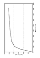
ところで、映像信号は一般に、ガンマー特性を有する8ビットのディジタル信号で記録されている。図8には、ガンマー処理された8ビットのディジタル映像信号と輝度との関係を例示している。TVやモニターなどの映像表示装置においても、その大半の処理はガンマー処理がかかったまま行なわれている。しかしながら、輝度調整や色温度調整、原色点変換などの一部の信号処理は、リニア信号にした方が回路構成を簡略化できる。このため、ガンマー処理された映像信号を一度デコード、すなわちデガンマー処理により映像信号のガンマー曲線をリニアなRGB信号(データ値と画素の輝度との関係が比例関係になる信号)に変換してから演算する必要がある。 By the way, the video signal is generally recorded as an 8-bit digital signal having a gamma characteristic. FIG. 8 illustrates the relationship between the luminance and the 8-bit digital video signal subjected to gamma processing. Even in video display devices such as TVs and monitors, most of the processing is performed with gamma processing applied. However, a part of signal processing such as luminance adjustment, color temperature adjustment, and primary color point conversion can be simplified by using a linear signal. For this reason, once the gamma-processed video signal is decoded, that is, after the gamma curve of the video signal is converted to a linear RGB signal (a signal in which the relationship between the data value and the luminance of the pixel is proportional) by degamma processing, the calculation is performed. There is a need to.
図9には、デガンマー処理してからリニア信号処理する回路構成を模式的に示している。デガンマー回路901は、8ビットの映像信号を入力すると、デガンマー処理してリニアRGB信号に変換する。そして、原色点変換部902、輝度調整部903、色温度調整部904はそれぞれ、リニアRGB信号に対して、原色点変換、輝度調整、色温度調整などのリニア信号処理を行なう。
FIG. 9 schematically shows a circuit configuration for performing linear signal processing after degamma processing. When an 8-bit video signal is input, the
デガンマー処理は、非線形演算であり負荷が重いため、専用のデガンマー回路を必要とする。また、リニアRGB信号で暗い映像信号を正しく表現するには、例えば映像信号に13ビットなどビット拡張を行なう必要がある。したがって、理想的な映像表示システムは、記録媒体などから再生された8ビットの映像信号をデガンマー処理して13ビットのリニアRGB信号に変換した後、さらに輝度調整や色温度調整、原色点変換などのリニア信号処理を行なってから表示出力するという構成となる。 The degamma process is a non-linear operation and has a heavy load, and therefore requires a dedicated degamma circuit. In addition, in order to correctly express a dark video signal with a linear RGB signal, it is necessary to perform bit extension such as 13 bits on the video signal. Therefore, an ideal video display system performs degamma processing on an 8-bit video signal reproduced from a recording medium and converts it into a 13-bit linear RGB signal, and further performs brightness adjustment, color temperature adjustment, primary color point conversion, and the like. After the linear signal processing is performed, the display is output.
図10には、デガンマー処理によりビット拡張したリニアRGB信号にリニア信号処理を行なってから表示出力する映像表示システム1000の構成例を模式的に示している。デガンマー回路1001は、8ビットの映像信号を入力すると、デガンマー処理してリニアRGB信号に変換し、さらに13ビットにビット拡張する。そして、原色点変換部1002、輝度調整部1003、色温度調整部1004はそれぞれ、13ビットのリニアRGB信号に対して、原色点変換、輝度調整、色温度調整などのリニア信号処理を行なう。このようにリニア信号処理された映像信号は、表示パネル1005で表示出力される。
FIG. 10 schematically illustrates a configuration example of a
以上を踏まえ、ヘッド・マウント・ディスプレイなどを表示装置に持つ、理想的な映像表示システムの構成方法について考察してみる。この種の映像表示システムは、表示部と表示部を駆動する表示駆動部からなる表示装置と、BDプレイヤーなどで再生された映像信号を表示装置に供給する映像供給装置で構成され、映像供給装置と表示装置間は映像信号インターフェースで接続されている。リニア信号処理を行なう前には映像信号にデガンマー処理を行なう必要があるが、デガンマー処理は負荷が重たいこと、デガンマー処理した後は映像信号がビット拡張されることから、システム内のどこでデガンマー処理並びにリニア信号処理を行なうべきかを十分検討すべきである。 Based on the above, let us consider an ideal video display system configuration method that has a head-mounted display or the like as a display device. This type of video display system includes a display device including a display unit and a display drive unit that drives the display unit, and a video supply device that supplies a video signal reproduced by a BD player or the like to the display device. And the display device are connected by a video signal interface. Before performing linear signal processing, it is necessary to perform degamma processing on the video signal. However, because degamma processing is heavy and the video signal is bit-extended after degamma processing, the degamma processing and where in the system It should be fully examined whether linear signal processing should be performed.
本明細書で開示する技術の目的は、表示装置と、映像信号を表示装置に供給する映像供給装置で構成され、映像供給装置と表示装置間は映像信号インターフェースで接続され、輝度調整や色温度調整、原色点変換などのリニア信号処理を行なった映像信号を表示装置で好適に表示出力することができる、優れた映像表示システム、映像供給装置、並びに表示装置を提供することにある。 An object of the technique disclosed in this specification is configured by a display device and a video supply device that supplies a video signal to the display device. The video supply device and the display device are connected by a video signal interface, and brightness adjustment and color temperature are performed. It is an object to provide an excellent video display system, video supply device, and display device that can suitably display and output a video signal subjected to linear signal processing such as adjustment and primary color point conversion on a display device.
本明細書で開示する技術のさらなる目的は、デガンマー処理は負荷が重たいこと、デガンマー処理した後は映像信号がビット拡張されることを考慮して、元の映像信号をデガンマー処理したリニアRGB信号に対してリニア信号処理を好適に行なうことができる、優れた映像表示システム、映像供給装置、並びに表示装置を提供することにある。 A further object of the technology disclosed in the present specification is to convert the original video signal into a linear RGB signal that is degamma processed in consideration of the heavy load on the degamma processing and the bit extension of the video signal after the degamma processing. An object of the present invention is to provide an excellent video display system, video supply device, and display device capable of suitably performing linear signal processing.
本願は、上記課題を参酌してなされたものであり、請求項1に記載の技術は、
映像信号をデガンマー処理してリニアRGB信号を得るデガンマー回路と、リニアRGB信号に対して第1のリニア信号処理を行なう第1のリニア信号処理部と、前記第1のリニア信号処理した後のリニアRGB信号をエンコードしてビット縮退する簡易ガンマー回路を有する映像供給装置と、
前記映像供給装置とは前記の縮退したビット長の映像信号インターフェースで接続され、ビット縮退したリニアRGB信号を元のビット長にデコードする簡易デガンマー回路と、前記デコードした後のリニアRGB信号に対して第2のリニア信号処理を行なう第2のリニア信号処理部と、前記第2のリニア信号処理した後のリニアRGB信号を表示出力する表示部を有する表示装置と、
を具備する映像表示システムである。
The present application has been made in consideration of the above problems, and the technology according to
A degamma circuit that obtains a linear RGB signal by degamma processing the video signal, a first linear signal processing unit that performs a first linear signal processing on the linear RGB signal, and a linear after the first linear signal processing. A video supply device having a simple gamma circuit that encodes RGB signals to degenerate bits;
The video supply device is connected to the video signal interface of the degenerate bit length, and a simple degamma circuit for decoding the bit RGB degenerate linear RGB signal to the original bit length, and the linear RGB signal after the decoding A display device having a second linear signal processing unit for performing second linear signal processing, and a display unit for displaying and outputting linear RGB signals after the second linear signal processing;
Is a video display system.
但し、ここで言う「システム」とは、複数の装置(又は特定の機能を実現する機能モジュール)が論理的に集合した物のことを言い、各装置や機能モジュールが単一の筐体内にあるか否かは特に問わない。 However, “system” here refers to a logical collection of a plurality of devices (or functional modules that realize specific functions), and each device or functional module is in a single housing. It does not matter whether or not.
本願の請求項2に記載の技術によれば、請求項1に記載の映像表示システムにおいて、前記映像供給装置側の簡易ガンマー回路は、線形演算によりリニアRGB信号をガンマー処理し、一方、前記表示装置側の簡易デガンマー回路は、ガンマー処理されたリニアRGB信号を線形演算によりデガンマー処理するように構成されている。
According to the technique described in claim 2 of the present application, in the video display system according to
本願の請求項3に記載の技術によれば、請求項1に記載の映像表示システムにおいて、前記映像供給装置側の簡易ガンマー回路は、入力領域を複数に分割し、分割した入力領域毎にガンマー曲線を近似した線分からなる近似ガンマー曲線を用いてリニアRGB信号をエンコードし、一方、前記表示装置側の簡易デガンマー回路は、前記近似ガンマー曲線とは逆特性となる近似デガンマー曲線を用いて、エンコードされたリニアRGB信号をデコードするように構成されている。 According to a third aspect of the present application, in the video display system according to the first aspect, the simple gamma circuit on the video supply device side divides the input area into a plurality of gamma values for each divided input area. The linear RGB signal is encoded using an approximate gamma curve composed of line segments approximating the curve. On the other hand, the simple degamma circuit on the display device side encodes using an approximate degamma curve having characteristics opposite to those of the approximate gamma curve. The linear RGB signal is decoded.
本願の請求項4に記載の技術によれば、請求項3に記載の映像表示システムは、前記簡易ガンマー回路と前記簡易デガンマー回路を組み合わせた入出力特性は、信号レベルが小さい領域において入出力が一致するように構成されている。 According to the technique described in claim 4 of the present application, the video display system according to claim 3 is characterized in that the input / output characteristics obtained by combining the simple gamma circuit and the simple degamma circuit are such that input / output is performed in a region where the signal level is small. Configured to match.
また、本願の請求項5に記載の技術は、
映像信号をデガンマー処理してリニアRGB信号を得るデガンマー回路と、
リニアRGB信号に対して第1のリニア信号処理を行なうリニア信号処理部と、
前記リニア信号処理した後のリニアRGB信号をエンコードしてビット縮退する簡易ガンマー回路と、
を具備する映像供給装置である。
Further, the technique described in claim 5 of the present application is:
A degamma circuit that obtains a linear RGB signal by degamma processing the video signal;
A linear signal processing unit that performs first linear signal processing on the linear RGB signal;
A simple gamma circuit that encodes the linear RGB signal after the linear signal processing and degenerates the bit;
Is a video supply device.
本願の請求項6に記載の技術によれば、請求項5に記載の映像供給装置は、前記簡易ガンマー回路が線形演算によりリニアRGB信号をガンマー処理するように構成されている。 According to the technology described in claim 6 of the present application, the video supply device described in claim 5 is configured such that the simple gamma circuit performs gamma processing on the linear RGB signal by linear calculation.
本願の請求項7に記載の技術によれば、請求項5に記載の映像供給装置は、前記簡易ガンマー回路が、入力領域を複数に分割し、分割した入力領域毎にガンマー曲線を近似した線分からなる近似ガンマー曲線を用いてリニアRGB信号をエンコードするように構成されている。 According to the seventh aspect of the present application, in the video supply device according to the fifth aspect, the simple gamma circuit divides the input area into a plurality of lines, and approximates a gamma curve for each divided input area. The linear RGB signal is encoded using an approximate gamma curve consisting of minutes.
また、本願の請求項8に記載の技術は、
映像供給装置と接続する映像信号インターフェースと、
前記映像供給装置でビット縮退したリニアRGB信号を前記映像信号インターフェース経由で入力して、元のビット長にデコードする簡易デガンマー回路と、
前記デコードした後のリニアRGB信号に対して第2のリニア信号処理を行なうリニア信号処理部と、
前記リニア信号処理した後のリニアRGB信号を表示出力する表示部と、
を具備する表示装置である。
Further, the technique described in claim 8 of the present application is:
A video signal interface connected to the video supply device;
A simple degamma circuit that inputs a linear RGB signal degenerated by the video supply device via the video signal interface and decodes it to the original bit length;
A linear signal processing unit that performs second linear signal processing on the decoded linear RGB signal;
A display unit for displaying and outputting linear RGB signals after the linear signal processing;
Is a display device.
本願の請求項9に記載の技術によれば、請求項8に記載の表示装置は、前記簡易デガンマー回路がガンマー処理されたリニアRGB信号を線形演算によりデガンマー処理するように構成されている。
According to the technology described in
本願の請求項10に記載の技術によれば、前記映像供給装置では、入力領域を複数に分割し、分割した入力領域毎にガンマー曲線を近似した線分からなる近似ガンマー曲線を用いてリニアRGB信号をエンコードしている。そして、請求項8に記載の表示装置は、前記簡易デガンマー回路が前記近似ガンマー曲線とは逆特性となる近似デガンマー曲線を用いてリニアRGB信号をデコードするように構成されている。
According to the technique of
本願の請求項11に記載の技術によれば、請求項8に記載の表示装置は、ヘッド・マウント・ディスプレイなど、ユーザーの頭部に直接装着して用いられるように構成されている。 According to the technology described in claim 11 of the present application, the display device described in claim 8 is configured to be used by being directly mounted on a user's head, such as a head-mounted display.
本明細書で開示する技術によれば、所定の映像信号インターフェースで接続された映像供給装置と表示装置で構成され、ヘッド・マウント・ディスプレイなどの表示装置側の信号処理負荷を低減しつつ、輝度調整や色温度調整、原色点変換などのリニア信号処理を行なった映像信号を表示装置で好適に表示出力することができる、優れた映像表示システム、映像供給装置、並びに表示装置を提供することができる。 According to the technology disclosed in this specification, a video supply device and a display device that are connected by a predetermined video signal interface are configured to reduce luminance while reducing a signal processing load on a display device such as a head-mounted display. To provide an excellent video display system, video supply device, and display device capable of suitably displaying and outputting a video signal subjected to linear signal processing such as adjustment, color temperature adjustment, and primary color point conversion on a display device. it can.
本明細書で開示する技術のさらに他の目的、特徴や利点は、後述する実施形態や添付する図面に基づくより詳細な説明によって明らかになるであろう。 Other objects, features, and advantages of the technology disclosed in the present specification will become apparent from a more detailed description based on the embodiments to be described later and the accompanying drawings.
以下、図面を参照しながら本明細書で開示する技術の実施形態について詳細に説明する。 Hereinafter, embodiments of the technology disclosed in this specification will be described in detail with reference to the drawings.
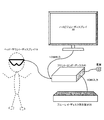
図1には、ヘッド・マウント・ディスプレイを含む画像表示システムの構成を模式的に示している。図示のシステムは、ヘッド・マウント・ディスプレイ10本体と、視聴コンテンツのソースとなるブルーレイ・ディスク再生装置20と、ブルーレイ・ディスク再生装置20の再生コンテンツの他の出力先となるハイビジョン・ディスプレイ(例えば、HDMI(High−Definition Mutlimedia Interface)対応テレビ)30と、ブルーレイ・ディスク再生装置20から出力されるAV信号の処理を行なうフロント・エンド・ボックス40で構成される。
FIG. 1 schematically shows the configuration of an image display system including a head-mounted display. The illustrated system includes a head mounted
フロント・エンド・ボックス40は、ブルーレイ・ディスク再生装置20から出力されるAV信号をHDMI入力すると、例えば信号処理して、HDMI出力するHDMIリピーターに相当する。また、フロント・エンド・ボックス40は、ブルーレイ・ディスク再生装置20の出力先をヘッド・マウント・ディスプレイ10又はハイビジョン・ディスプレイ30のいずれかに切り替える2出力スイッチャーでもある。図示の例では、フロント・エンド・ボックス40は2出力であるが、3以上の出力を有していてもよい。但し、フロント・エンド・ボックス40は、AV信号の出力先を排他的とし、且つ、ヘッド・マウント・ディスプレイ10への出力を最優先とする。
The
ブルーレイ・ディスク再生装置20とフロント・エンド・ボックス40間、並びに、フロント・エンド・ボックス40とハイビジョン・ディスプレイ30間は、それぞれHDMIケーブルで接続されている。フロント・エンド・ボックス40とヘッド・マウント・ディスプレイ10間も、HDMIケーブルで接続するように構成することも可能であるが、その他の仕様のケーブルを用いてAV信号をシリアル転送するようにしてもよい。但し、フロント・エンド・ボックス40とヘッド・マウント・ディスプレイ10間を接続するケーブル1本で、AV信号と電力を供給するものとし、ヘッド・マウント・ディスプレイ10はこのケーブルを介して駆動電力も得ることができる。
The Blu-ray
ヘッド・マウント・ディスプレイ10は、左眼用及び右眼用の独立した表示部を備えている。各表示部は、例えば有機EL素子を用いている。また、左右の各表示部は、低歪みで且つ高解像度の広視野角光学系からなるレンズ・ブロックを装備している。
The head mounted
図1に示した映像表示システムにおいて、ヘッド・マウント・ディスプレイ10は、表示部と表示部を駆動する表示駆動部からなる表示装置に相当し、フロント・エンド・ボックス40は、ブルーレイ・ディスク再生装置20で再生された映像信号を表示装置に供給する映像供給装置に相当し、映像供給装置と表示装置間は所定の映像信号インターフェースで接続されている、ということができる。
In the video display system shown in FIG. 1, the head mounted
通常、ブルーレイ・ディスク再生装置20から映像表示システムに入力される再生信号は、例えば8ビットのガンマー処理がかかったままの映像信号である。理想的な映像表示システムでは、図10に示したように、8ビットの映像信号をデガンマー処理して13ビットのリニアRGB信号に変換した後、さらに輝度調整や色温度調整、原色点変換などのリニア信号処理を行なってから表示出力することになる。
Normally, the playback signal input from the Blu-ray
以上を踏まえ、図1に示した映像表示システムの理想的な構成方法について、改めて考察してみる。リニア信号処理を行なう前には映像信号にデガンマー処理を行なう必要があるが、デガンマー処理は負荷が重たいこと、デガンマー処理した後は映像信号がビット拡張されることから、システム内のどこでデガンマー処理並びにリニア信号処理を行なうべきかを十分検討すべきである。 Based on the above, let us consider again the ideal configuration method of the video display system shown in FIG. Before performing linear signal processing, it is necessary to perform degamma processing on the video signal. However, because degamma processing is heavy and the video signal is bit-extended after degamma processing, the degamma processing and where in the system It should be fully examined whether linear signal processing should be performed.
図11には、デガンマー以降の処理をすべてヘッド・マウント・ディスプレイ10内で行なう映像表示システム1100の構成例を模式的に示している。映像供給装置としてのフロント・エンド・ボックス40は、入力した映像データをデコーダー1101でデコードして8ビットの映像信号を得ると、前処理部1102でスケーリング、ノイズリダクションなどの前処理を施した後、8ビットの映像信号のままヘッド・マウント・ディスプレイ10に転送する。表示装置すなわちヘッド・マウント・ディスプレイ10側では、入力した8ビットの映像信号をデガンマー回路1103でデガンマー処理し、さらにビット拡張して13ビットのリニアRGB信号を得る。その後、13ビットのリニアRGB信号に対し、原色点変換部1104、輝度調整部1105、色温度調整部1106でそれぞれ原色点変換、輝度調整、色温度調整などのリニア信号処理を施した後、表示パネル1107で表示出力される。
FIG. 11 schematically shows a configuration example of a video display system 1100 that performs all processes after degamma within the head-mounted
図11に示すようにデガンマー以降の処理をヘッド・マウント・ディスプレイ10内で行なう場合、信号処理量が多くなるため、消費電力と発熱量の増大を招来し、以下のような問題を引き起こす。
As shown in FIG. 11, when processing after degamma is performed in the head mounted
(1)熱によって表示部の劣化が促進される。特に有機EL素子を用いる場合、劣化は顕著となる。
(2)ヘッド・マウント・ディスプレイ10のようにユーザーが直接装着する装置の場合、温度の上昇は、ユーザーの安全性や装着の快適性という点でも問題である。
(1) Deterioration of the display unit is promoted by heat. In particular, when an organic EL element is used, the deterioration becomes significant.
(2) In the case of a device that is directly worn by the user, such as the head-mounted
これに対し、ヘッド・マウント・ディスプレイ10内で行なう信号処理量を抑えるために、処理の重いデガンマー処理と上記のリニア信号処理の少なくとも一部をフロント・エンド・ボックス40側で行なうという解決方法もある。
On the other hand, in order to suppress the amount of signal processing performed in the head-mounted
図12には、デガンマー処理と一部のリニア信号処理をフロント・エンド・ボックス40内で行なう映像表示システム1200の構成例を模式的に示している。フロント・エンド・ボックス40は、入力した映像データをデコーダー1201でデコードして8ビットの映像信号を得ると、前処理部1202でスケーリング、ノイズリダクションなどの前処理を施した後、デガンマー回路1203でデガンマー処理して、ビット拡張して13ビットのリニアRGB信号を得ると、さらに原色点変換部1204で、原色点変換処理を行なう。そして、原色点変換後の13ビットのリニアRGB信号をフロント・エンド・ボックス40からヘッド・マウント・ディスプレイ10に転送する。ヘッド・マウント・ディスプレイ10側では、13ビットのリニアRGB信号に対し、輝度調整部1205及び色温度調整部1206で輝度調整、色温度調整などの残りのリニア信号処理を施した後、表示パネル1207で表示出力される。
FIG. 12 schematically shows a configuration example of a
図12に示したシステム構成例では、ヘッド・マウント・ディスプレイ10内で行なう信号処理量が低減されるが、フロント・エンド・ボックス40とヘッド・マウント・ディスプレイ10間をビット拡張した13ビットの信号インターフェースで接続する必要がある。ところが、DVI(Digital Video Interactive)やDisplayPortといった一般的な映像信号インターフェースでは、10ビット程度のビット長に制限される。このようにビット長が不足すると、階調表現が劣化するという画質的な問題が発生してしまう。
In the system configuration example shown in FIG. 12, the amount of signal processing performed in the head mounted
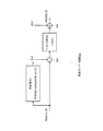
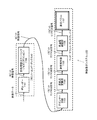
これに対し、図2には、デガンマー処理と一部のリニア信号処理をフロント・エンド・ボックス40内で行なうとともに、10ビット程度のビット長に制限される映像信号インターフェースでフロント・エンド・ボックス40とヘッド・マウント・ディスプレイ10間が接続される映像表示システム200の構成例を示している。
On the other hand, in FIG. 2, the degamma processing and some linear signal processing are performed in the
フロント・エンド・ボックス40は、入力した映像データをデコーダー201でデコードして8ビットの映像信号を得ると、前処理部202でスケーリング、ノイズリダクションなどの前処理を施した後、デガンマー回路203でデガンマー処理して、ビット拡張して13ビットのリニアRGB信号を得ると、さらに原色点変換部204で原色点変換処理を行なう。デガンマー処理と一部のリニア信号処理をフロント・エンド・ボックス40内で行なう点では、図12に示したシステム構成と同様である。但し、フロント・エンド・ボックス40における信号処理の最終段に、簡易ガンマー回路205を追加する点で相違する。この簡易ガンマー回路205は、13ビットのリニアRGB信号を簡易ガンマーRGB信号にエンコードして10ビット長に縮退する。
When the
また、ヘッド・マウント・ディスプレイ10の入力段に、簡易デガンマー回路206を追加する。この簡易デガンマー回路206は、入力された10ビットの簡易ガンマーRGB信号をリニアRGB信号にデコードして、元の13ビットに復元する。これにより、映像表示システムは、フロント・エンド・ボックス40とヘッド・マウント・ディスプレイ10の間を、10ビットの映像信号インターフェースで接続することができる。その後、ヘッド・マウント・ディスプレイ10内では、13ビット長にデコードした後のリニアRGB信号に対し、輝度調整部207及び色温度調整部208で輝度調整、色温度調整などの残りのリニア信号処理を施した後、表示パネル209で表示出力される。
In addition, a simple degamma circuit 206 is added to the input stage of the head mounted
本来のデガンマー処理は非線形演算であり負荷が重い。このため、13ビットのリニアRGB信号を10ビットのRGB信号にエンコードし、さらに10ビットのリニアRGB信号にデコードする際に、通常のガンマー処理及びデガンマー処理を行なうと、ヘッド・マウント・ディスプレイ10内での信号処理量が多くなり、消費電力と発熱量の増大を招来する。
The original degamma process is a non-linear operation and is heavy. For this reason, when normal gamma processing and degamma processing are performed when a 13-bit linear RGB signal is encoded into a 10-bit RGB signal and further decoded into a 10-bit linear RGB signal, the inside of the head mounted
そこで、本実施形態では、線形演算で済む簡易ガンマー処理及び簡易デガンマー処理を導入することにより、フロント・エンド・ボックス40とヘッド・マウント・ディスプレイ10間を10ビットの映像信号インターフェースで接続することを可能にするとともに、ヘッド・マウント・ディスプレイ10での信号処理量を抑え、消費電力と発熱量の増大を防ぐようにしている。
Therefore, in this embodiment, the
なお、図2に示した構成例では、リニアRGB信号に対するリニア信号処理のうち、フロント・エンド・ボックス40側では原色点変換部を行ない、ヘッド・マウント・ディスプレイ10側では輝度調整並びに色温度調整を行なうが、フロント・エンド・ボックス40及びヘッド・マウント・ディスプレイ10の各々で行なうリニア信号処理を入れ替えたり、各リニア信号処理を実行する順序を入れ替えたりすることは可能である。
In the configuration example shown in FIG. 2, in the linear signal processing for the linear RGB signal, the primary color point conversion unit is performed on the
以下では、簡易ガンマー回路205で行なう簡易ガンマー処理、並びに、簡易デガンマー回路206で行なう簡易デガンマー処理の詳細について説明する。 Hereinafter, the details of the simple gamma process performed by the simple gamma circuit 205 and the simple degamma process performed by the simple degamma circuit 206 will be described.
通常のガンマー処理では、べき乗ガンマーからなるガンマー曲線を用いて、ガンマー入力をガンマー出力に変換して、映像信号のビット長を削減することができる。また、デガンマー処理では、ガンマー処理とは逆の操作、すなわち、元のガンマー曲線とは逆関数となる曲線を用いて、映像信号のビット長を元に戻す。 In normal gamma processing, a bit length of a video signal can be reduced by converting a gamma input into a gamma output using a gamma curve composed of a power gamma. In the degamma process, the bit length of the video signal is restored to the original by using an operation opposite to that of the gamma process, that is, using a curve that is an inverse function of the original gamma curve.
ガンマー処理及びデガンマー処理は非線形演算であり、負荷が重い。そこで、本実施形態では、ガンマー曲線を複数本の線分で近似した近似ガンマー曲線を用いて簡易ガンマー処理及び簡易デガンマー処理を行なうことにした。このような簡易ガンマー処理及び簡易デガンマー処理は、線形演算であり負荷が軽い。したがって、ヘッド・マウント・ディスプレイ10の入力段に簡易デガンマー回路を配置しても、消費電力や発熱量の増大を招来することはない。
Gamma processing and degamma processing are non-linear operations and are heavily loaded. Therefore, in this embodiment, simple gamma processing and simple degamma processing are performed using an approximate gamma curve obtained by approximating a gamma curve with a plurality of line segments. Such simple gamma processing and simple degamma processing are linear operations and lightly loaded. Therefore, even if a simple degamma circuit is arranged at the input stage of the head-mounted
図3には、簡易ガンマー回路205の入出力特性例を示している。図示の例では、入力領域は、0〜511、512〜1023、1024〜2047、2048〜4095、4096〜8192の5つの領域に分け、各々の領域において順に傾き20、2-1、2-3、2-5、2-6の直線でそれぞれガンマー曲線を近似する。したがって、近似ガンマー曲線は、下式(1)に示すよう5本の線分で表わされる。 FIG. 3 shows an example of input / output characteristics of the simple gamma circuit 205. In the illustrated example, the input area is divided into five areas of 0 to 511, 512 to 1023, 1024 to 2047, 2048 to 4095, and 4096 to 8192, and each area has an inclination of 2 0 , 2 −1 , 2 − in order. 3 Approximate the gamma curve with straight lines of 2 -5 and 2 -6 respectively. Therefore, the approximate gamma curve is represented by five line segments as shown in the following formula (1).

図4には、上記の近似ガンマー曲線に従った簡易ガンマー処理を実現する簡易ガンマー回路205の構成例を示している。図示の簡易ガンマー回路では、まず判定部401が、13ビットの入力信号IRGBを閾値と比較して、0〜511、512〜1023、1024〜2047、2048〜4095、4096〜8192のいずれの領域内であるかに応じて、m=0〜4の5通りの場合分けを行ない、各変数i[m]、o[m]、a[m]を決定する。そして、減算部402で、入力信号IRGBからi[m]を引いた後、ビットシフト部403でa[m]だけ下位にビットシフトする。さらに、加算部404でo[m]を加えて出力する。
FIG. 4 shows a configuration example of a simple gamma circuit 205 that realizes simple gamma processing according to the above approximate gamma curve. In the illustrated simple gamma circuit, the determination unit 401 first compares the 13-bit input signal IRGB with a threshold value, and in any region of 0 to 511, 512 to 1023, 1024 to 2047, 2048 to 4095, and 4096 to 8192. Depending on whether or not, m is divided into five cases of 0 to 4, and each variable i [m], o [m], a [m] is determined. The
簡易ガンマー回路205で行なう上記の処理は、要するに下式(2)に従って、入力信号xを簡易ガンマー処理して出力yを得ることである。その入出力特性は、図3に示した通りである。 The above processing performed by the simple gamma circuit 205 is to obtain the output y by performing simple gamma processing on the input signal x in accordance with the following equation (2). The input / output characteristics are as shown in FIG.
また、図5には、簡易デガンマー回路206の入出力特性例を示している。図示の例では、入力領域は、0〜511、512〜767、768〜959、960〜1024の5つの領域に分け、各々の領域において順に傾き2-6、2-5、2-3、2-1、20の直線でそれぞれデガンマー曲線を近似する。したがって、近似デガンマー曲線は、下式(3)に示すよう5本の線分で表わされる。これはちょうど図3とは逆特性となっている。 FIG. 5 shows an input / output characteristic example of the simple degamma circuit 206. In the example shown in the figure, the input area is divided into five areas of 0 to 511, 512 to 767, 768 to 959, and 960 to 1024. In each area, the slope is 2 −6 , 2 −5 , 2 −3 , 2 -1, respectively of 2 0 linear approximate the Deganma curve. Therefore, the approximate degamma curve is represented by five line segments as shown in the following equation (3). This is exactly the reverse characteristic of FIG.
図6には、上記の近似デガンマー曲線に従った簡易デガンマー処理を実現する簡易デガンマー回路206の構成例を示している。図示の簡易デガンマー回路では、まず判定部601が、13ビットの入力信号IRGBを閾値と比較して、0〜511、512〜767、768〜895、896〜959、959〜1024のいずれの領域内であるかに応じて、m=0〜4の5通りの場合分けを行ない、各変数i[m]、o[m]、a[m]を決定する。そして、減算部602で、入力信号IRGBからi[m]を引いた後、ビットシフト部603でa[m]だけ上位にビットシフトする。さらに、加算部604でo[m]を加えて出力する。
FIG. 6 shows a configuration example of a simple degamma circuit 206 that realizes simple degamma processing according to the above approximate degamma curve. In the illustrated simple degamma circuit, the determination unit 601 first compares the 13-bit input signal IRGB with a threshold value, and in any region of 0 to 511, 512 to 767, 768 to 895, 896 to 959, and 959 to 1024. Depending on whether or not, m is divided into five cases of 0 to 4, and each variable i [m], o [m], a [m] is determined. Then, after subtracting i [m] from the input signal IRGB by the subtracting
簡易デガンマー回路206で行なう上記の処理は、要するに下式(4)に従って、入力信号xを簡易デガンマー処理して出力yを得ることである。その入出力特性は、図5に示した通りである。 The above-described processing performed by the simple degamma circuit 206 is to obtain the output y by performing simple degamma processing on the input signal x according to the following equation (4). The input / output characteristics are as shown in FIG.
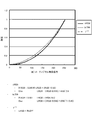
図7には、図4に示した簡易ガンマー回路205と図6に示した簡易デガンマー回路206を組み合わせた入出力特性を示している。同図から、信号レベルが小さい領域では入出力が一致し、信号レベルが大きい領域になるほど一致しなくなっているのが分かる。これは、簡易ガンマー回路で信号レベルが大きいほど、近似ガンマー曲線の傾きを決定する成分a[m]が大きくなってビットシフトが起こり、階調表現が劣化するためである。しかし、人間の目は信号レベルが小さい領域では感度が高いが、信号レベルが大きい領域では低いので、ほぼ劣化がないように知覚させることができる。 FIG. 7 shows input / output characteristics obtained by combining the simple gamma circuit 205 shown in FIG. 4 and the simple degamma circuit 206 shown in FIG. From the figure, it can be seen that the input and output match in the region where the signal level is low, and that the higher the signal level, the lower the match. This is because, as the signal level in the simple gamma circuit is larger, the component a [m] that determines the slope of the approximate gamma curve becomes larger, bit shift occurs, and gradation expression deteriorates. However, the human eye has high sensitivity in a region where the signal level is low, but is low in a region where the signal level is high, so that it can be perceived so that there is almost no deterioration.
図4に示した簡易ガンマー回路と図6に示した簡易デガンマー回路はいずれも、乗算器などの複雑な処理は必要とせず、基本的に、加算器とビットシフトだけで構成される。したがって、通常のデガンマー回路などと比べると、はるかに小規模な回路で実現することが可能である。 Both the simple gamma circuit shown in FIG. 4 and the simple degamma circuit shown in FIG. 6 do not require complicated processing such as a multiplier, and basically include only an adder and a bit shift. Therefore, it can be realized with a much smaller circuit than a normal degamma circuit.
なお、本明細書の開示の技術は、以下のような構成をとることも可能である。
(1)映像信号をデガンマー処理してリニアRGB信号を得るデガンマー回路と、リニアRGB信号に対して第1のリニア信号処理を行なう第1のリニア信号処理部と、前記第1のリニア信号処理した後のリニアRGB信号をエンコードしてビット縮退する簡易ガンマー回路を有する映像供給装置と、前記映像供給装置とは前記の縮退したビット長の映像信号インターフェースで接続され、ビット縮退したリニアRGB信号を元のビット長にデコードする簡易デガンマー回路と、前記デコードした後のリニアRGB信号に対して第2のリニア信号処理を行なう第2のリニア信号処理部と、前記第2のリニア信号処理した後のリニアRGB信号を表示出力する表示部を有する表示装置を具備する映像表示システム。
(2)前記簡易ガンマー回路は、線形演算によりリニアRGB信号をガンマー処理し、前記簡易デガンマー回路は、ガンマー処理されたリニアRGB信号を線形演算によりデガンマー処理する、上記(1)に記載の映像表示システム。
(3)前記簡易ガンマー回路は、入力領域を複数に分割し、分割した入力領域毎にガンマー曲線を近似した線分からなる近似ガンマー曲線を用いてリニアRGB信号をエンコードし、前記簡易デガンマー回路は、前記近似ガンマー曲線とは逆特性となる近似デガンマー曲線を用いて、エンコードされたリニアRGB信号をデコードする、上記(1)に記載の映像表示システム。
(4)前記簡易ガンマー回路と前記簡易デガンマー回路を組み合わせた入出力特性は、信号レベルが小さい領域において入出力が一致する、上記(3)に記載の映像表示システム。
(5)映像信号をデガンマー処理してリニアRGB信号を得るデガンマー回路と、リニアRGB信号に対して第1のリニア信号処理を行なうリニア信号処理部と、前記リニア信号処理した後のリニアRGB信号をエンコードしてビット縮退する簡易ガンマー回路を具備する映像供給装置。
(6)前記簡易ガンマー回路は、線形演算によりリニアRGB信号をガンマー処理する、上記(5)に記載の映像供給装置。
(7)前記簡易ガンマー回路は、入力領域を複数に分割し、分割した入力領域毎にガンマー曲線を近似した線分からなる近似ガンマー曲線を用いてリニアRGB信号をエンコードする、上記(5)に記載の映像供給装置。
(8)映像供給装置と接続する映像信号インターフェースと、前記映像供給装置でビット縮退したリニアRGB信号を前記映像信号インターフェース経由で入力して、元のビット長にデコードする簡易デガンマー回路と、前記デコードした後のリニアRGB信号に対して第2のリニア信号処理を行なうリニア信号処理部と、前記リニア信号処理した後のリニアRGB信号を表示出力する表示部を具備する表示装置。
(9)前記簡易デガンマー回路は、ガンマー処理されたリニアRGB信号を線形演算によりデガンマー処理する、上記(8)に記載の表示装置。
(10)前記映像供給装置では、入力領域を複数に分割し、分割した入力領域毎にガンマー曲線を近似した線分からなる近似ガンマー曲線を用いてリニアRGB信号をエンコードしており、前記簡易デガンマー回路は、前記近似ガンマー曲線とは逆特性となる近似デガンマー曲線を用いて、エンコードされたリニアRGB信号をデコードする、上記(8)に記載の表示装置。
(11)ユーザーの頭部に直接装着して用いられる、上記(8)に記載の表示装置。
Note that the technology disclosed in the present specification can also be configured as follows.
(1) A degamma circuit that obtains a linear RGB signal by degamma processing the video signal, a first linear signal processing unit that performs a first linear signal processing on the linear RGB signal, and the first linear signal processing. A video supply device having a simple gamma circuit that encodes a later linear RGB signal and degenerates the bit, and the video supply device is connected by the video signal interface of the degenerated bit length, and is based on the linear RGB signal that has been degenerated. A simple degamma circuit that decodes to a bit length of the second linear signal, a second linear signal processing unit that performs second linear signal processing on the decoded linear RGB signal, and a linear after the second linear signal processing An image display system including a display device having a display unit for displaying and outputting RGB signals.
(2) The video display according to (1), wherein the simple gamma circuit performs gamma processing on a linear RGB signal by linear calculation, and the simple degamma circuit performs degamma processing on the linear RGB signal subjected to gamma processing by linear calculation. system.
(3) The simple gamma circuit divides an input area into a plurality of parts, encodes a linear RGB signal using an approximate gamma curve composed of line segments approximating the gamma curve for each divided input area, and the simple degamma circuit includes: The video display system according to (1), wherein the encoded linear RGB signal is decoded using an approximate degamma curve having a characteristic opposite to that of the approximate gamma curve.
(4) The video display system according to (3), wherein input / output characteristics obtained by combining the simple gamma circuit and the simple degamma circuit match in input and output in a region where the signal level is low.
(5) A degamma circuit that obtains a linear RGB signal by degamma processing the video signal, a linear signal processing unit that performs a first linear signal processing on the linear RGB signal, and a linear RGB signal after the linear signal processing. A video supply device including a simple gamma circuit that encodes and degenerates bits.
(6) The video supply device according to (5), wherein the simple gamma circuit performs gamma processing on the linear RGB signal by linear calculation.
(7) The simple gamma circuit divides an input area into a plurality of parts, and encodes a linear RGB signal using an approximate gamma curve including a line segment that approximates the gamma curve for each divided input area. Picture supply device.
(8) A video signal interface connected to the video supply device, a simple degamma circuit that inputs a linear RGB signal degenerated by the video supply device via the video signal interface and decodes it to the original bit length, and the decoding A display device comprising: a linear signal processing unit that performs second linear signal processing on the linear RGB signal after being processed; and a display unit that displays and outputs the linear RGB signal after the linear signal processing.
(9) The display device according to (8), wherein the simple degamma circuit degamma-processes the gamma-processed linear RGB signal by linear calculation.
(10) In the video supply device, the input region is divided into a plurality of portions, and the linear RGB signal is encoded using an approximate gamma curve composed of a line segment that approximates the gamma curve for each divided input region, and the simple degamma circuit The display device according to (8), wherein the encoded linear RGB signal is decoded using an approximate degamma curve having a characteristic opposite to that of the approximate gamma curve.
(11) The display device according to (8), which is used by being directly attached to a user's head.
以上、特定の実施形態を参照しながら、本明細書で開示する技術について詳細に説明してきた。しかしながら、本明細書で開示する技術の要旨を逸脱しない範囲で当業者が該実施形態の修正や代用を成し得ることは自明である。 As described above, the technology disclosed in this specification has been described in detail with reference to specific embodiments. However, it is obvious that those skilled in the art can make modifications and substitutions of the embodiments without departing from the scope of the technology disclosed in this specification.
本明細書では、本明細書で開示する技術をヘッド・マウント・ディスプレイに適用した実施形態を中心に説明してきたが、本明細書で開示する技術の要旨は特定の映像表示システムの構成に限定されるものではない。所定の映像信号インターフェースで接続された映像供給装置と表示装置で構成され、映像信号に対してリニア信号処理を行なうさまざまなタイプの映像表示システムに対して、同様に本明細書で開示する技術を適用することができる。 Although the present specification has mainly described the embodiment in which the technology disclosed in this specification is applied to a head-mounted display, the gist of the technology disclosed in this specification is limited to the configuration of a specific video display system. Is not to be done. The technology disclosed in this specification is similarly applied to various types of video display systems that are configured by a video supply device and a display device connected by a predetermined video signal interface and perform linear signal processing on the video signal. Can be applied.
要するに、例示という形態で本明細書で開示する技術について説明してきたのであり、本明細書の記載内容を限定的に解釈するべきではない。本明細書で開示する技術の要旨を判断するためには、特許請求の範囲を参酌すべきである。 In short, the technology disclosed in the present specification has been described in the form of exemplification, and the description content of the present specification should not be interpreted in a limited manner. In order to determine the gist of the technology disclosed in this specification, the claims should be taken into consideration.
10…ヘッド・マウント・ディスプレイ
20…ブルーレイ・ディスク再生装置
30…ハイビジョン・ディスプレイ
40…フロント・エンド・ボックス
200…映像表示システム
201…デコーダー
202…前処理部
203…デガンマー回路
204…原色点変換部
205…簡易ガンマー回路
206…簡易デガンマー回路
207…輝度調整部
208…色温度調整部
209…表示パネル
401…判定部
402…減算部
403…ビットシフト部
404…加算部
601…判定部
602…減算部
603…ビットシフト部
604…加算部
DESCRIPTION OF
Claims (11)
前記映像供給装置とは前記の縮退したビット長の映像信号インターフェースで接続され、ビット縮退したリニアRGB信号を元のビット長にデコードする簡易デガンマー回路と、前記デコードした後のリニアRGB信号に対して第2のリニア信号処理を行なう第2のリニア信号処理部と、前記第2のリニア信号処理した後のリニアRGB信号を表示出力する表示部を有する表示装置と、
を具備する映像表示システム。 A degamma circuit that obtains a linear RGB signal by degamma processing the video signal, a first linear signal processing unit that performs a first linear signal processing on the linear RGB signal, and a linear after the first linear signal processing. A video supply device having a simple gamma circuit that encodes RGB signals to degenerate bits;
The video supply device is connected to the video signal interface of the degenerate bit length, and a simple degamma circuit for decoding the bit RGB degenerate linear RGB signal to the original bit length, and the linear RGB signal after the decoding A display device having a second linear signal processing unit for performing second linear signal processing, and a display unit for displaying and outputting linear RGB signals after the second linear signal processing;
A video display system comprising:
前記簡易デガンマー回路は、ガンマー処理されたリニアRGB信号を線形演算によりデガンマー処理する、
請求項1に記載の映像表示システム。 The simple gamma circuit performs gamma processing on linear RGB signals by linear calculation,
The simple degamma circuit degamma-processes the gamma-processed linear RGB signal by linear calculation.
The video display system according to claim 1.
前記簡易デガンマー回路は、前記近似ガンマー曲線とは逆特性となる近似デガンマー曲線を用いて、エンコードされたリニアRGB信号をデコードする、
請求項1に記載の映像表示システム。 The simple gamma circuit divides an input area into a plurality of parts, encodes a linear RGB signal using an approximate gamma curve composed of line segments approximating a gamma curve for each divided input area,
The simple degamma circuit decodes the encoded linear RGB signal using an approximate degamma curve having a characteristic opposite to that of the approximate gamma curve.
The video display system according to claim 1.
請求項3に記載の映像表示システム。 The input / output characteristics combining the simple gamma circuit and the simple degamma circuit match the input / output in a region where the signal level is small.
The video display system according to claim 3.
リニアRGB信号に対して第1のリニア信号処理を行なうリニア信号処理部と、
前記リニア信号処理した後のリニアRGB信号をエンコードしてビット縮退する簡易ガンマー回路と、
を具備する映像供給装置。 A degamma circuit that obtains a linear RGB signal by degamma processing the video signal;
A linear signal processing unit that performs first linear signal processing on the linear RGB signal;
A simple gamma circuit that encodes the linear RGB signal after the linear signal processing and degenerates the bit;
A video supply device comprising:
請求項5に記載の映像供給装置。 The simple gamma circuit performs gamma processing on a linear RGB signal by linear calculation.
The video supply device according to claim 5.
請求項5に記載の映像供給装置。 The simple gamma circuit divides an input area into a plurality of parts, and encodes a linear RGB signal using an approximate gamma curve composed of a line segment approximating a gamma curve for each divided input area.
The video supply device according to claim 5.
前記映像供給装置でビット縮退したリニアRGB信号を前記映像信号インターフェース経由で入力して、元のビット長にデコードする簡易デガンマー回路と、
前記デコードした後のリニアRGB信号に対して第2のリニア信号処理を行なうリニア信号処理部と、
前記リニア信号処理した後のリニアRGB信号を表示出力する表示部と、
を具備する表示装置。 A video signal interface connected to the video supply device;
A simple degamma circuit that inputs a linear RGB signal degenerated by the video supply device via the video signal interface and decodes it to the original bit length;
A linear signal processing unit that performs second linear signal processing on the decoded linear RGB signal;
A display unit for displaying and outputting linear RGB signals after the linear signal processing;
A display device comprising:
請求項8に記載の表示装置。 The simple degamma circuit degamma-processes the gamma-processed linear RGB signal by linear calculation.
The display device according to claim 8.
前記簡易デガンマー回路は、前記近似ガンマー曲線とは逆特性となる近似デガンマー曲線を用いて、エンコードされたリニアRGB信号をデコードする、
請求項8に記載の表示装置。 In the video supply device, the input region is divided into a plurality of segments, and the linear RGB signal is encoded using an approximate gamma curve composed of line segments that approximate the gamma curve for each divided input region,
The simple degamma circuit decodes the encoded linear RGB signal using an approximate degamma curve having a characteristic opposite to that of the approximate gamma curve.
The display device according to claim 8.
請求項8に記載の表示装置。
Used directly on the user's head,
The display device according to claim 8.
Priority Applications (1)
| Application Number | Priority Date | Filing Date | Title |
|---|---|---|---|
| JP2011222368A JP2013085045A (en) | 2011-10-06 | 2011-10-06 | Video display system, video supply device, and display device |
Applications Claiming Priority (1)
| Application Number | Priority Date | Filing Date | Title |
|---|---|---|---|
| JP2011222368A JP2013085045A (en) | 2011-10-06 | 2011-10-06 | Video display system, video supply device, and display device |
Publications (2)
| Publication Number | Publication Date |
|---|---|
| JP2013085045A true JP2013085045A (en) | 2013-05-09 |
| JP2013085045A5 JP2013085045A5 (en) | 2014-10-09 |
Family
ID=48529820
Family Applications (1)
| Application Number | Title | Priority Date | Filing Date |
|---|---|---|---|
| JP2011222368A Abandoned JP2013085045A (en) | 2011-10-06 | 2011-10-06 | Video display system, video supply device, and display device |
Country Status (1)
| Country | Link |
|---|---|
| JP (1) | JP2013085045A (en) |
Cited By (1)
| Publication number | Priority date | Publication date | Assignee | Title |
|---|---|---|---|---|
| JP2016012073A (en) * | 2014-06-30 | 2016-01-21 | 株式会社ジャパンディスプレイ | Display device |
-
2011
- 2011-10-06 JP JP2011222368A patent/JP2013085045A/en not_active Abandoned
Cited By (1)
| Publication number | Priority date | Publication date | Assignee | Title |
|---|---|---|---|---|
| JP2016012073A (en) * | 2014-06-30 | 2016-01-21 | 株式会社ジャパンディスプレイ | Display device |
Similar Documents
| Publication | Publication Date | Title |
|---|---|---|
| US10319078B2 (en) | Image signal processing apparatus and image signal processing method to suppress color shift caused by lens distortion | |
| JP5062674B2 (en) | System, method, and computer program product for compensating for crosstalk when displaying stereo content | |
| US20190340734A1 (en) | Display method and display device | |
| US20130241947A1 (en) | Display device, image processing device, image processing method, and computer program | |
| JP5862112B2 (en) | Head mounted display and display control method | |
| US20140198192A1 (en) | Display device and display control method | |
| EP3512188B1 (en) | Image processing apparatus and image processing method, and program | |
| CN111316204A (en) | Display system | |
| JP2013257457A (en) | Display device, display controlling method and program | |
| US9524681B2 (en) | Backlight modulation over external display interfaces to save power | |
| JPWO2016157839A1 (en) | Signal processing apparatus, recording / reproducing apparatus, signal processing method, and program | |
| US8330857B2 (en) | Display apparatus and control method thereof | |
| JP6407496B1 (en) | Video playback device | |
| JP2013085045A (en) | Video display system, video supply device, and display device | |
| JP4966400B2 (en) | Image output apparatus and image output method | |
| US9094712B2 (en) | Video processing device, display device and video processing method | |
| US8472742B2 (en) | Signal processing device, signal processing method, and program | |
| KR20130118178A (en) | Display device and method compressing and transmitting data thereof | |
| JP2013115520A (en) | Three-dimensional video display device and three-dimensional video display device operation method | |
| KR20110009021A (en) | Display apparatus and method for displaying thereof | |
| US20140192863A1 (en) | Perceptual lossless compression of image data for transmission on uncompressed video interconnects | |
| US20090322954A1 (en) | Dynamic selection of 3d comb filter based on motion | |
| US8878837B2 (en) | Image processing apparatus having on-screen display function and method thereof | |
| JP2009162944A (en) | Liquid crystal display device |
Legal Events
| Date | Code | Title | Description |
|---|---|---|---|
| A521 | Written amendment |
Free format text: JAPANESE INTERMEDIATE CODE: A523 Effective date: 20140822 |
|
| A621 | Written request for application examination |
Free format text: JAPANESE INTERMEDIATE CODE: A621 Effective date: 20140822 |
|
| A762 | Written abandonment of application |
Free format text: JAPANESE INTERMEDIATE CODE: A762 Effective date: 20150401 |