JP2013083310A - Double wall blow molded body - Google Patents
Double wall blow molded body Download PDFInfo
- Publication number
- JP2013083310A JP2013083310A JP2011223700A JP2011223700A JP2013083310A JP 2013083310 A JP2013083310 A JP 2013083310A JP 2011223700 A JP2011223700 A JP 2011223700A JP 2011223700 A JP2011223700 A JP 2011223700A JP 2013083310 A JP2013083310 A JP 2013083310A
- Authority
- JP
- Japan
- Prior art keywords
- rib
- wall
- double
- double wall
- blow molded
- Prior art date
- Legal status (The legal status is an assumption and is not a legal conclusion. Google has not performed a legal analysis and makes no representation as to the accuracy of the status listed.)
- Granted
Links
Images


Landscapes
- Body Structure For Vehicles (AREA)
- Vibration Dampers (AREA)
- Blow-Moulding Or Thermoforming Of Plastics Or The Like (AREA)
Abstract
【課題】圧縮初期のクッション性が高く、圧縮荷重によるリブの倒れが防止でき、衝撃吸収性の高い2重壁ブロー成形体を得る。
【解決手段】壁1から壁2に向けて窪んだ凹溝状の第1リブ3と、壁2から壁1に向けて窪んだ凹溝状の第2リブ4が形成され、両リブ3,4は平面視で略直交する。第1リブ3と第2リブ4は、それぞれ底壁12,15が2重壁の略中央部に位置し、交叉部16において底壁12,15同士が互いに溶着している。第1リブ3と第2リブ4は噛み合っていることが望ましい。第1リブ3及び第2リブ4は抜き勾配を有し、2重壁の厚み方向に圧縮荷重が作用してこの2重壁ブロー成形体が圧壊変形するとき、第1リブ3の両側壁10,11、及び第2リブ4の両側壁13,14がそれぞれ凹溝の内側に張り出し、圧壊変形の過程で互いに接触し、相手側の曲げ変形を妨害し圧縮荷重に対する抵抗力を増大させる。
【選択図】図2A double wall blow molded article having a high cushioning property at the initial stage of compression, being able to prevent ribs from collapsing due to a compressive load, and having high impact absorption.
A groove-shaped first rib 3 recessed from the wall 1 toward the wall 2 and a groove-shaped second rib 4 recessed from the wall 2 toward the wall 1 are formed. 4 is substantially orthogonal in plan view. In the first rib 3 and the second rib 4, the bottom walls 12 and 15 are positioned at substantially the center of the double wall, and the bottom walls 12 and 15 are welded to each other at the crossing portion 16. The first rib 3 and the second rib 4 are desirably engaged with each other. The first rib 3 and the second rib 4 have a draft angle, and when the compressive load acts in the thickness direction of the double wall and the double wall blow molded body undergoes crushing deformation, both side walls 10 of the first rib 3 11 and both side walls 13 and 14 of the second rib 4 project inside the concave groove and contact each other in the process of crushing deformation, obstructing the other side bending deformation and increasing the resistance to compressive load.
[Selection] Figure 2
Description
本発明は、2重壁の両壁から対向壁に向けて窪んだ補強用のリブが形成された2重壁ブロー成形体に関し、特にクッション性を改良した2重壁ブロー成形体に関する。 The present invention relates to a double wall blow molded article in which reinforcing ribs that are recessed from both walls of a double wall toward an opposing wall are formed, and more particularly to a double wall blow molded article having improved cushioning properties.
特許文献1の図1には、2重壁の両壁から対向壁に向けて窪んだ複数個の凹状(筒状)リブが形成された2重壁ブロー成形体が記載されている。2重壁の一方の壁から他方の壁に向けて窪んだ凹状リブと、2重壁の他方の壁から一方の壁に向けて窪んだ凹状リブが対をなし、対をなす凹状リブは2重壁の中央部で互いの頂部が溶着し、又は頂部が近接配置されている。特許文献1の記載によれば、この2重壁ブロー成形体は、圧壊変形の途中で急に剛性が低下することが防止され、高い衝撃吸収性が継続するため、車両の衝撃吸収体として適する。
FIG. 1 of
特許文献2の図5には、2重壁の両壁から対向壁に向けて窪み、互いに平行な複数列の凹状(溝状)リブが形成された2重壁ブロー成形体が記載されている。各凹状リブは列の長さ方向に沿って断面が略台形の第1リブと、頂部を含む全部又は大部分が板状をなす第2リブからなる。2重壁の一方の壁から他方の壁に向けて窪んだ凹状リブと、2重壁の他方の壁から一方の壁に向けて窪んだ凹状リブが対をなし、対をなす凹状リブの第1リブの頂部同士が凹状リブの長さ方向に沿って2重壁の中央部で溶着している。特許文献2の記載によれば、この2重壁ブロー成形体は、曲げ荷重、せん断荷重及び圧縮荷重に対する抵抗力が強く座屈が起こりにくいことから、フロアボード、自動車の床材、パレット等として適する。
FIG. 5 of
特許文献1,2に記載された2重壁ブロー成形体は、全ての凹状リブが対向壁から窪む凹状リブと対をなし、2重壁の略中央部で頂部同士が溶着し又は近接して配置されているため、圧縮荷重に対する抵抗力(圧縮剛性)が圧縮初期に高く、圧縮初期のクッション性(衝撃を和らげる機能)が小さい。また、特許文献1の2重壁ブロー成形体では凹状リブが筒状であるため、特許文献2の2重壁ブロー成形体では全ての凹状リブが同一方向に配列しているため、圧縮荷重により厚さ方向に圧壊(潰れ)が進むと、いずれも荷重の向きによっては凹状リブが倒れやすく、その場合、圧縮荷重に対する抵抗力が減少し衝撃吸収性(エネルギー吸収量)も低下する。
In the double wall blow molded article described in
本発明は、2重壁の両壁から対向壁に向けて窪んだ補強用のリブが形成された2重壁ブロー成形体についてのこのような問題点を解決するためになされたもので、圧縮初期のクッション性が高く、圧縮荷重によるリブの倒れが防止できる2重壁ブロー成形体を得ることを目的とする。 The present invention has been made to solve such a problem with a double-wall blow molded body in which reinforcing ribs that are recessed from both walls of the double wall toward the opposite wall are formed. An object of the present invention is to obtain a double wall blow molded article that has a high initial cushioning property and can prevent the rib from collapsing due to a compressive load.
本発明に係る2重壁ブロー成形体は、2重壁の一方の壁から他方の壁に向けて窪んだ凹溝状の第1リブが1列又は複数列形成され、前記他方の壁から前記一方の壁に向けて窪んだ第2リブが1列又は複数列形成され、前記第1,第2リブは平面視で略直交し、それぞれ底壁が2重壁の対向壁に達せず、交叉部において底壁同士が互いに溶着していることを特徴とする。前記第1リブと第2リブは噛み合っていることが望ましい。また、前記第1,第2リブは抜き勾配を有し、2重壁の厚み方向に圧縮荷重が作用して圧壊変形するとき、各リブの両側壁が凹溝の内側に張り出し、圧壊変形の過程で互いに接触することが望ましい。 In the double-wall blow molded article according to the present invention, one or more rows of groove-shaped first ribs that are recessed from one wall of the double wall toward the other wall are formed, The second ribs that are recessed toward one wall are formed in one or a plurality of rows, the first and second ribs are substantially orthogonal in a plan view, and the bottom walls do not reach the opposing walls of the double walls. The bottom walls are welded to each other at the portion. The first rib and the second rib are preferably engaged with each other. Further, the first and second ribs have a draft angle, and when the compressive load acts in the thickness direction of the double wall and the crushing deformation occurs, both side walls of each rib project to the inside of the concave groove, and the crushing deformation It is desirable to contact each other in the process.
本発明に係る2重壁ブロー成形体は、前記第1,第2リブが平面視で略直交し、底壁が対向壁に溶着せず、かつ両リブが交叉部のみで互いに溶着している。このため、圧縮初期の圧縮荷重に対する抵抗力が従来の2重壁ブロー成形体(特許文献1,2参照)に比べて小さく、圧縮初期のクッション性が高い。また、圧縮荷重によるリブの倒れが防止でき、それに伴い圧壊変形の過程で衝撃吸収性の低下も防止できる。特に、圧壊変形するとき各リブの両側壁が凹溝の内側に張り出し、圧壊変形の過程で互いに接触するようになっていると、圧壊変形に伴って抵抗力が増大し衝撃吸収性も高くなる。
In the double-wall blow molded article according to the present invention, the first and second ribs are substantially orthogonal in a plan view, the bottom wall is not welded to the opposing wall, and both ribs are welded to each other only at the intersection. . For this reason, the resistance force to the compressive load at the initial stage of compression is smaller than that of the conventional double wall blow-molded body (see
以下、図1〜7を参照して、本発明に係る2重壁ブロー成形体について説明する。
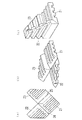
図1,2に示す2重壁ブロー成形体は、2重壁の壁1,2と、壁1から壁2に向けて窪んだ凹溝状の第1リブ3と、壁2から壁1に向けて窪んだ凹溝状の第2リブ4と、壁1,2の4周を囲む周壁5〜8からなる。9は金型のパーティングライン、20は加圧エア吹込穴である。
第1リブ3は断面が略台形状で抜き勾配を有し、傾斜した両側壁10,11と底壁12からなり、底壁12は2重壁の厚みのほぼ中央部に位置している。第2リブ4も同じく傾斜した両側壁13,14と底壁15からなり、底壁15は2重壁の厚みのほぼ中央部に位置している。第1リブ3と第2リブ4の凹溝の深さ(底壁12の壁1からの深さ、底壁15の壁2からの深さ)は,第1リブ3及び第2リブ4の長さ方向に沿ってほぼ一定である。第1リブ3と第2リブ4は平面視で直交し、交叉部16において底壁12,15が互いに溶着し一体化している。
Hereinafter, with reference to FIGS. 1-7, the double wall blow molded object which concerns on this invention is demonstrated.
The double wall blow molded body shown in FIGS. 1 and 2 includes
The
図3に本発明に係る別の2重壁ブロー成形体を示す。図3において、図1,2に示す2重壁ブロー成形体と実質的に同一部位には同じ番号を付与している。
図3に示す2重壁ブロー成形体(断面図のみ)は、図1,2に示す2重壁ブロー成形体と外観形状がほぼ一致し(従って、斜視図は図1を援用する)、第1リブ3と第2リブ4が凹溝状に窪み、底壁12,15が2重壁の厚みのほぼ中央部に位置している点、及び第1リブ3と第2リブ4が交叉部16において互いに溶着し一体化している点も、図1に示す2重壁ブロー成形体と同じである。
FIG. 3 shows another double wall blow molded article according to the present invention. In FIG. 3, the same reference numerals are assigned to substantially the same parts as the double wall blow molded article shown in FIGS.
The double wall blow-molded body shown in FIG. 3 (only the cross-sectional view) is substantially identical in appearance to the double wall blow-molded body shown in FIGS. 1 and 2 (therefore, the perspective view uses FIG. 1). The 1
しかし、第2リブ4の凹溝の深さ(底壁15の壁2からの深さ)が一定でなく、第2リブ4の長さ方向に沿って異なる点で、図1に示す2重壁ブロー成形体と異なる。具体的には、第2リブ4の凹溝の深さ(底壁15の壁2からの深さ)は、第1リブ3との交叉部16において浅く、交叉部16の両側で深くなっている。従って、前記交叉部16において第1リブ3と第2リブ4は噛み合った状態(第1リブ3が第2リブ4に食い込んだ状態)にあるということができる。この構造により第1リブ3及び第2リブは、圧縮荷重による倒れに対してより強くなる。
However, the double groove shown in FIG. 1 is different in that the depth of the concave groove of the second rib 4 (the depth of the
図4に本発明に係る別の2重壁ブロー成形体を示す。図4において、図1,2に示す2重壁ブロー成形体と実質的に同一部位には同じ番号を付与している。
図4に示す2重壁ブロー成形体(断面図のみ)は、図1,2に示す2重壁ブロー成形体と外観形状がほぼ一致し(従って、斜視図は図1を援用する)、第1リブ3と第2リブ4が凹溝状に窪み、底壁12,15が2重壁の厚みのほぼ中央部に位置している点、及び第1リブ3と第2リブ4が交叉部16において互いに溶着し一体化している点も、図1に示す2重壁ブロー成形体と同じである。
FIG. 4 shows another double wall blow molded article according to the present invention. In FIG. 4, the same numbers are assigned to substantially the same parts as the double wall blow molded article shown in FIGS.
The double wall blow-molded body shown in FIG. 4 (cross-sectional view only) is substantially identical in appearance to the double-wall blow molded body shown in FIGS. 1 and 2 (therefore, the perspective view uses FIG. 1). The 1
しかし、第1リブ3と第2リブ4の凹溝の深さ(底壁12の壁1からの深さ、底壁15の壁2からの深さ)が一定でなく、それぞれ第1リブ3、第2リブ4の長さ方向に沿って異なる点で、図1に示す2重壁ブロー成形体と異なる。具体的には、第1リブ3と第2リブ4の凹溝の深さ(底壁12の壁1からの深さ、底壁15の壁2からの深さ)は、交叉部16において浅く、交叉部16の両側で深くなっている。従って、前記交叉部16において、第1リブ3と第2リブ4は互いに噛み合った状態にあるということができる。この構造により第1リブ3及び第2リブは、圧縮荷重による倒れに対してより強くなる。
However, the depths of the concave grooves of the
図1〜4に示した第1リブ3は略台形状であったが、図5に示すように、第1リブ3は他の抜き勾配の形態をとることができる。図示しないが第2リブ4も同様である。図5において、図2に示す第1リブ3と実質的に同一部位には同じ番号を付与している。
図5(a)に示す第1リブ3は、両側壁10,11が凹溝の内側に張り出す湾曲形状を有する。図5(b)に示す第1リブ3は、両側壁10,11が凹溝の内側に凸となる折れ部17,18を有する。
Although the
The
図6は、本発明に係る2重壁ブロー成形体に圧縮荷重を加えて圧壊変形したときの2重壁の厚さ(元の厚さを1としたときの変形後の比率)−圧縮応力のグラフと対応する変形形態を示す模式図である。なお、2重壁ブロー成形体は、ブロー成形後、加圧エア吹込口20(図1参照)を閉じて、中空内部を密閉しておくことが望ましい。その場合、圧縮変形が進むにつれて2重壁ブロー成形体の内圧が上昇し、それにより圧縮荷重が増大し衝撃吸収性も向上する。 FIG. 6 shows the thickness of the double wall when the compressive load is applied to the double wall blow molded article according to the present invention (the ratio after deformation when the original thickness is 1) −compressive stress. It is a schematic diagram which shows the modification corresponding to this graph. In addition, after a blow molding, it is desirable for a double wall blow molded object to close the pressurized air blowing port 20 (refer FIG. 1), and to seal the hollow interior. In that case, the internal pressure of the double-wall blow molded body increases as the compression deformation proceeds, thereby increasing the compression load and improving the shock absorption.
2重壁ブロー成形体の厚み方向に圧縮荷重が加わると、圧縮初期は比較的低い圧縮荷重で、第1,第2リブ3,4の側壁10,11,13,14、及び周壁5〜8が湾曲し、2重壁ブロー成形体は厚み方向に圧縮変形する。2重壁ブロー成形体の中空内部を密閉した場合も、圧縮初期は内圧の上昇が少ないので、密閉に伴う圧縮荷重の増加は少なく、圧縮初期のクッション性は阻害されない。圧縮初期の圧縮荷重は、第1リブ3と壁1のコーナーR及び第2リブ4と壁2のコーナーR(図2に矢印19で示す)の大きさで調整(コーナーRが大きいほど圧縮荷重が小さくなる)することができる。
When a compressive load is applied in the thickness direction of the double wall blow molded body, the
この圧縮変形の過程で、第1リブ3の側壁9と側壁11、及び第2リブ4の側壁13と側壁14は、それぞれ凹溝の内側に張り出すように曲げ変形し、さらに圧縮変形が進むと、第1リブ3,第2リブ4の長さ方向に沿って互いに接触する。接触した第1リブ3の側壁10と側壁11、及び第2リブ4の側壁13と側壁14は、互いに相手側の曲げ変形を妨害する形になり、その結果、圧縮荷重に対する抵抗力が低下せずむしろ増大する。なお、各リブの側壁同士の接触がない場合、座屈により抵抗力が急激に低下する可能性がある。
In the process of compressive deformation, the
図7は,本発明に係る2重壁ブロー成形体からなる製品保護用のコーナーパッドを示す。この種のコーナーパッドは、ダンボールに製品を収納するとき,ダンボールのコーナー部に配置されて製品を保護するためのもので、従来は発泡スチロールで形成されている。
図7のコーナーパッドは、3つの2重壁ブロー成形体21,22,23が一体成形されたもので、2重壁ブロー成形体22,23が平面視矩形の2重壁ブロー成形体21の隣接する辺にそれぞれ薄肉で屈曲自在のヒンジ部24,25を介して接続されている。コーナーパッドとして使用するときは、図7(c)に示すように、2重壁ブロー成形体22,23を2重壁ブロー成形体21に対し垂直に立ち上げる。
このコーナーパッドは軽量で、初期のクッション性が高く衝撃吸収力が高い。また、輸送時は図7(a)に示すように平らにして嵩を減らすことができる。
FIG. 7 shows a corner pad for product protection comprising a double wall blow molded article according to the present invention. This type of corner pad is disposed at the corner portion of the cardboard to protect the product when the product is stored in the cardboard, and is conventionally formed of foamed polystyrene.
The corner pad shown in FIG. 7 is formed by integrally molding three double wall blow molded
This corner pad is lightweight and has high initial cushioning and high shock absorption. Moreover, at the time of transportation, as shown in FIG.
1,2 2重壁の壁
3 第1リブ
4 第2リブ
9,11,13,14 リブの側壁
12,15 リブの底壁
16 第1,第2リブの交叉部
1, 2
Claims (3)
Priority Applications (1)
| Application Number | Priority Date | Filing Date | Title |
|---|---|---|---|
| JP2011223700A JP5588416B2 (en) | 2011-10-11 | 2011-10-11 | Double wall blow molding |
Applications Claiming Priority (1)
| Application Number | Priority Date | Filing Date | Title |
|---|---|---|---|
| JP2011223700A JP5588416B2 (en) | 2011-10-11 | 2011-10-11 | Double wall blow molding |
Publications (2)
| Publication Number | Publication Date |
|---|---|
| JP2013083310A true JP2013083310A (en) | 2013-05-09 |
| JP5588416B2 JP5588416B2 (en) | 2014-09-10 |
Family
ID=48528695
Family Applications (1)
| Application Number | Title | Priority Date | Filing Date |
|---|---|---|---|
| JP2011223700A Active JP5588416B2 (en) | 2011-10-11 | 2011-10-11 | Double wall blow molding |
Country Status (1)
| Country | Link |
|---|---|
| JP (1) | JP5588416B2 (en) |
Cited By (1)
| Publication number | Priority date | Publication date | Assignee | Title |
|---|---|---|---|---|
| WO2015045808A1 (en) * | 2013-09-26 | 2015-04-02 | キョーラク株式会社 | Impact-energy-absorbing body |
Citations (1)
| Publication number | Priority date | Publication date | Assignee | Title |
|---|---|---|---|---|
| JPH01174122U (en) * | 1988-05-31 | 1989-12-11 |
-
2011
- 2011-10-11 JP JP2011223700A patent/JP5588416B2/en active Active
Patent Citations (1)
| Publication number | Priority date | Publication date | Assignee | Title |
|---|---|---|---|---|
| JPH01174122U (en) * | 1988-05-31 | 1989-12-11 |
Cited By (3)
| Publication number | Priority date | Publication date | Assignee | Title |
|---|---|---|---|---|
| WO2015045808A1 (en) * | 2013-09-26 | 2015-04-02 | キョーラク株式会社 | Impact-energy-absorbing body |
| JPWO2015045808A1 (en) * | 2013-09-26 | 2017-03-09 | キョーラク株式会社 | Impact energy absorber |
| US10006515B2 (en) | 2013-09-26 | 2018-06-26 | Kyoraku Co., Ltd. | Impact energy absorber |
Also Published As
| Publication number | Publication date |
|---|---|
| JP5588416B2 (en) | 2014-09-10 |
Similar Documents
| Publication | Publication Date | Title |
|---|---|---|
| JP5261490B2 (en) | Shock absorbing member | |
| KR101852696B1 (en) | Crush box and method for manufacturing same | |
| JP5549964B2 (en) | Frame structure for vehicles with excellent collision resistance | |
| JP6061787B2 (en) | Bumper reinforcement | |
| JP6913029B2 (en) | Energy absorbing member | |
| US11208150B2 (en) | Automotive frame member and electric vehicle | |
| JP5852483B2 (en) | Bumper reinforcement | |
| JP5029859B2 (en) | Synthetic resin housing | |
| JP2017100743A (en) | Decompression absorption bottle | |
| JP2010107027A (en) | Shock absorbing body for vehicle | |
| JP5655374B2 (en) | Shock absorber | |
| JP2013044407A (en) | Shock absorbing member | |
| JP5588416B2 (en) | Double wall blow molding | |
| JP5179390B2 (en) | Energy absorbing member | |
| JP4842188B2 (en) | Plastic container | |
| JP6492842B2 (en) | Shock absorber for vehicle | |
| JP5055539B2 (en) | Square shape can | |
| JP5882020B2 (en) | Shock absorbing member | |
| JP5761051B2 (en) | Vehicle shock absorbing member and vehicle end structure | |
| KR101369725B1 (en) | The crash box used a car | |
| JP5750405B2 (en) | Pressure vessel | |
| JP6651758B2 (en) | Synthetic resin container | |
| JP2014092182A (en) | Impact absorption structure | |
| JP5966187B2 (en) | Bumper reinforcement | |
| JP5483182B2 (en) | Synthetic plastic round bottle |
Legal Events
| Date | Code | Title | Description |
|---|---|---|---|
| A621 | Written request for application examination |
Free format text: JAPANESE INTERMEDIATE CODE: A621 Effective date: 20131021 |
|
| A131 | Notification of reasons for refusal |
Free format text: JAPANESE INTERMEDIATE CODE: A131 Effective date: 20140520 |
|
| A977 | Report on retrieval |
Free format text: JAPANESE INTERMEDIATE CODE: A971007 Effective date: 20140522 |
|
| A521 | Request for written amendment filed |
Free format text: JAPANESE INTERMEDIATE CODE: A523 Effective date: 20140616 |
|
| TRDD | Decision of grant or rejection written | ||
| A01 | Written decision to grant a patent or to grant a registration (utility model) |
Free format text: JAPANESE INTERMEDIATE CODE: A01 Effective date: 20140701 |
|
| A61 | First payment of annual fees (during grant procedure) |
Free format text: JAPANESE INTERMEDIATE CODE: A61 Effective date: 20140725 |
|
| R150 | Certificate of patent or registration of utility model |
Ref document number: 5588416 Country of ref document: JP Free format text: JAPANESE INTERMEDIATE CODE: R150 |
|
| R250 | Receipt of annual fees |
Free format text: JAPANESE INTERMEDIATE CODE: R250 |
|
| R250 | Receipt of annual fees |
Free format text: JAPANESE INTERMEDIATE CODE: R250 |
|
| R250 | Receipt of annual fees |
Free format text: JAPANESE INTERMEDIATE CODE: R250 |
|
| R250 | Receipt of annual fees |
Free format text: JAPANESE INTERMEDIATE CODE: R250 |
|
| R250 | Receipt of annual fees |
Free format text: JAPANESE INTERMEDIATE CODE: R250 |
|
| R250 | Receipt of annual fees |
Free format text: JAPANESE INTERMEDIATE CODE: R250 |
|
| R250 | Receipt of annual fees |
Free format text: JAPANESE INTERMEDIATE CODE: R250 |
|
| R250 | Receipt of annual fees |
Free format text: JAPANESE INTERMEDIATE CODE: R250 |
|
| R250 | Receipt of annual fees |
Free format text: JAPANESE INTERMEDIATE CODE: R250 |
|
| R250 | Receipt of annual fees |
Free format text: JAPANESE INTERMEDIATE CODE: R250 |