JP2013080553A - Hardware-based methods and apparatus for inter-track interference mitigation in magnetic recording systems - Google Patents
Hardware-based methods and apparatus for inter-track interference mitigation in magnetic recording systems Download PDFInfo
- Publication number
- JP2013080553A JP2013080553A JP2012215775A JP2012215775A JP2013080553A JP 2013080553 A JP2013080553 A JP 2013080553A JP 2012215775 A JP2012215775 A JP 2012215775A JP 2012215775 A JP2012215775 A JP 2012215775A JP 2013080553 A JP2013080553 A JP 2013080553A
- Authority
- JP
- Japan
- Prior art keywords
- data
- iti
- read
- mitigation
- sector
- Prior art date
- Legal status (The legal status is an assumption and is not a legal conclusion. Google has not performed a legal analysis and makes no representation as to the accuracy of the status listed.)
- Withdrawn
Links
Images


Classifications
-
- G—PHYSICS
- G11—INFORMATION STORAGE
- G11B—INFORMATION STORAGE BASED ON RELATIVE MOVEMENT BETWEEN RECORD CARRIER AND TRANSDUCER
- G11B5/00—Recording by magnetisation or demagnetisation of a record carrier; Reproducing by magnetic means; Record carriers therefor
- G11B5/02—Recording, reproducing, or erasing methods; Read, write or erase circuits therefor
- G11B5/09—Digital recording
-
- G—PHYSICS
- G11—INFORMATION STORAGE
- G11B—INFORMATION STORAGE BASED ON RELATIVE MOVEMENT BETWEEN RECORD CARRIER AND TRANSDUCER
- G11B5/00—Recording by magnetisation or demagnetisation of a record carrier; Reproducing by magnetic means; Record carriers therefor
- G11B5/02—Recording, reproducing, or erasing methods; Read, write or erase circuits therefor
-
- G—PHYSICS
- G11—INFORMATION STORAGE
- G11B—INFORMATION STORAGE BASED ON RELATIVE MOVEMENT BETWEEN RECORD CARRIER AND TRANSDUCER
- G11B19/00—Driving, starting, stopping record carriers not specifically of filamentary or web form, or of supports therefor; Control thereof; Control of operating function ; Driving both disc and head
- G11B19/02—Control of operating function, e.g. switching from recording to reproducing
- G11B19/04—Arrangements for preventing, inhibiting, or warning against double recording on the same blank or against other recording or reproducing malfunctions
- G11B19/041—Detection or prevention of read or write errors
- G11B19/045—Detection or prevention of read or write errors by detecting mistracking
-
- G—PHYSICS
- G11—INFORMATION STORAGE
- G11B—INFORMATION STORAGE BASED ON RELATIVE MOVEMENT BETWEEN RECORD CARRIER AND TRANSDUCER
- G11B5/00—Recording by magnetisation or demagnetisation of a record carrier; Reproducing by magnetic means; Record carriers therefor
- G11B5/012—Recording on, or reproducing or erasing from, magnetic disks
Abstract
Description
本発明は、概して、磁気記録システムに関し、より具体的には、そのような磁気記録システムにおけるトラック間干渉の影響を軽減するための改善された技術に関する。 The present invention relates generally to magnetic recording systems, and more specifically to improved techniques for mitigating the effects of inter-track interference in such magnetic recording systems.
磁気記録(MR)システムにおいて、データは、通常、一連の小さな磁気領域として、磁気媒体上の同心円状のトラックに記録される。所与のトラックに隣接するトラックに書き込まれたデータは、所与のトラックの媒体から読み出される信号に影響を与える。1つまたは複数の隣接するトラックの結果として所与のトラックの読み取り中に引き起こされる信号は、クロストークまたはトラック間干渉(ITI)と呼ばれる。所与のトラックの読み出される信号内の、隣接するトラックによって引き起こされたITI雑音の軽減は、概して、ITI軽減回路またはプロセスに与えられる隣接するトラックからのデータパターンについての情報に頼る。 In a magnetic recording (MR) system, data is typically recorded on concentric tracks on a magnetic medium as a series of small magnetic regions. Data written to a track adjacent to a given track affects the signal read from the media of the given track. The signal caused during the reading of a given track as a result of one or more adjacent tracks is called crosstalk or inter-track interference (ITI). The mitigation of ITI noise caused by adjacent tracks in the read signal of a given track generally relies on information about the data pattern from the adjacent track provided to the ITI mitigation circuit or process.
ITIは、データの同心円状のまたはらせん状のトラックが、媒体に、ヘッドのサイズに比して互いにごく近くに記録されるハードディスクドライブ(HDD)において特に問題である。ディスクドライブの容量は、トラックをより近くにまとめて配置することによって増やされる。しかし、ITIは、テクノロジーの微細化とともに増大することが知られており、トラックの分離距離が短くなるにつれて重大な雑音源になる。トラックがより近くにまとめて配置されるにつれて、隣接するトラックは、所与のトラックが媒体から読み出されるときにその所与のトラックの信号により影響を与えやすくなり、全体的な信号対雑音比を低下させる。したがって、ITIは、磁気媒体の所与の領域に信頼性高く記憶され得るトラックの数を制限する。ITIは、トラックが一部のケースでは互いに接触するほど近くに配置され、その他のケースではデータを書き込まれたときに互いに重なる可能性さえあるシングルド磁気記録(Shingled Magnetic Recording)(SMR)システムにおいては一層大きな問題である。 ITI is particularly problematic in hard disk drives (HDDs) in which concentric or spiral tracks of data are recorded on a medium very close to each other relative to the size of the head. Disk drive capacity is increased by placing tracks closer together. However, ITI is known to increase with technology miniaturization and becomes a significant noise source as the track separation distance decreases. As tracks are placed closer together, adjacent tracks are more susceptible to the signal of a given track when the given track is read from the media, resulting in an overall signal-to-noise ratio. Reduce. Thus, ITI limits the number of tracks that can be reliably stored in a given area of the magnetic media. ITIs are located in a single magnetic recording (SMR) system where the tracks are placed so close that they touch each other in some cases and can even overlap each other when data is written in other cases. It is a bigger problem.
磁気記録システムにおけるITIの影響を軽減するためのいくつかの技術が、提案されている。例えば、既存のSMRの実装においては、軽減プロセスが、通常、ハードディスクコントローラ(HDC)のソフトウェアによって実行される。しかし、ITIの軽減が有効化されるとき、HDCは、ディスクの3〜6回転ごとに数セクタ(および典型的には1セクタのみ)よりも多いセクタを再生するのに十分なほど速くデータを処理することができないことが分かっている。しかし、ディスクの各回転は、(例えば、使用される特定のディスクドライブ、プラッタのサイズ、およびディスク上の各トラックの半径方向の位置に応じて)例えば、500以上のセクタを含む可能性がある。 Several techniques have been proposed to mitigate the effects of ITI in magnetic recording systems. For example, in existing SMR implementations, the mitigation process is typically performed by hard disk controller (HDC) software. However, when ITI mitigation is enabled, the HDC can store data fast enough to play more than a few sectors (and typically only one sector) every 3-6 revolutions of the disk. I know I can't handle it. However, each rotation of the disk can include, for example, more than 500 sectors (eg, depending on the particular disk drive used, the size of the platter, and the radial position of each track on the disk). .
したがって、ITIの影響を軽減するための改善された技術に対するニーズが、存在する。ITIの影響を軽減するためのハードウェアに基づく技術に対するさらなるニーズが、存在する。ハードディスクコントローラがITIの計算を実行することを要求しない、ITIの影響を軽減するためのハードウェアに基づく技術に対するさらに別のニーズが、存在する。 Thus, there is a need for improved techniques for reducing the impact of ITI. There is a further need for hardware-based technology to mitigate the impact of ITI. There is yet another need for hardware-based techniques to mitigate the effects of ITI that do not require the hard disk controller to perform ITI calculations.
概して、磁気記録システムにおけるトラック間干渉の軽減のためのハードウェアに基づく方法および装置が、提供される。本発明の一態様によれば、トラック間干渉(ITI)が、ITIキャンセル・データを取得することと、ITIキャンセル・データを、読み取り動作中に、磁気記録システムの書き込みデータ経路を用いてITI軽減回路に提供することとによって磁気記録システムにおいて軽減される。任意的に、書き込みデータ経路は、読み取りデータ経路が読み取り動作を実行するのと実質的に同時に動作することができる。 In general, a hardware-based method and apparatus for mitigating inter-track interference in a magnetic recording system is provided. According to one aspect of the present invention, inter-track interference (ITI) acquires ITI cancellation data, and ITI cancellation data is read using a write data path of a magnetic recording system during a read operation. Mitigation in a magnetic recording system by providing a circuit. Optionally, the write data path can operate substantially simultaneously with the read data path performing a read operation.
ITIキャンセル・データは、例えば、書き込みデータ経路の外部にあるメモリから得られる可能性がある。ITIキャンセル・データは、例えば、ユーザ・データおよび/または媒体データを含む。一実施形態において、書き込みデータ経路は、ユーザ・データをITIの軽減のための媒体データに変換する。 The ITI cancellation data may be obtained from, for example, a memory outside the write data path. The ITI cancellation data includes, for example, user data and / or media data. In one embodiment, the write data path converts user data into media data for ITI mitigation.
ITIの軽減は、データの所与のセクタに対して選択的に有効化されることができる。加えて、ITIの軽減は、1つまたは複数の隣接するトラックに関する所与の読み取り動作に対して選択的に実行され得る。任意的に、ITIの軽減は、ITIを補正されたデータを後処理するための後処理手順と組み合わせて実行される可能性があり、および/または後処理されたデータに対してITIの軽減を実行する可能性がある。 ITI mitigation can be selectively enabled for a given sector of data. In addition, ITI mitigation can be performed selectively for a given read operation on one or more adjacent tracks. Optionally, ITI mitigation may be performed in combination with post-processing procedures for post-processing ITI-corrected data and / or ITI mitigation for post-processed data. There is a possibility to execute.
本発明、ならびに本発明のさらなる特徴および利点のより完全な理解が、以下の詳細な説明および図面を参照することによって得られる。 A more complete understanding of the present invention, as well as further features and advantages of the present invention, will be obtained by reference to the following detailed description and drawings.
本発明は、磁気記録システムにおけるトラック間干渉の軽減のためのハードウェアに基づく方法および装置を提供する。ITIの軽減は、正しいデータ再生の見込みを高めるために、媒体から読み取られるデータを追加的なデータ(以降、「キャンセル・データ」と呼ばれる)と組み合わせる。キャンセル・データは、ITI軽減回路またはプロセスに供給されなければならない。キャンセル・データは、当業者に明らかであろうように、ディスク媒体から読み取られるか、または別のソースから取得され得る。 The present invention provides a hardware-based method and apparatus for reducing track-to-track interference in a magnetic recording system. ITI mitigation combines data read from the media with additional data (hereinafter referred to as “cancellation data”) to increase the likelihood of correct data reproduction. Cancel data must be provided to the ITI mitigation circuit or process. The cancellation data can be read from the disk media or obtained from another source, as will be apparent to those skilled in the art.
本発明の一態様によれば、開示されたトラック間干渉の軽減のためのハードウェアに基づく技術は、HDCからキャンセル・データを取得するが、HDCの処理ユニットがITIの計算を実行することを要求しない。本発明の別の態様によれば、後のデジタル信号処理(DSP)のために読み取りデータ経路に示すためのキャンセル・データを記憶し、供給し、操作し、それによって、書き込まれたデータを正しく再生する可能性を高めるためのシステムが、開示された。 According to one aspect of the present invention, the disclosed hardware-based technique for mitigating inter-track interference obtains cancellation data from the HDC, but the HDC processing unit performs the ITI calculation. Do not request. According to another aspect of the present invention, cancellation data for storing in the read data path for later digital signal processing (DSP) is stored, provided, and manipulated so that the written data is correctly A system for increasing the likelihood of playback has been disclosed.
リード・チャネルは、通常、所与の時間に読み取りモードかまたは書き込みモードのいずれかであるスレーブ・デバイスである。各モードで、データは、通常、一方向にしか流れない。例えば、データは、書き込みモードにおいては、ハードディスクコントローラ(HDC)から、媒体へのリード・チャネル(RC)に流れ、読み取りモードにおいては、媒体からRCへ流れ、次いでHDCへと流れる。本発明は、書き込みデータ経路(WDP)の少なくとも一部が、リード・チャネルが読み取りモードで読み取り動作を実行しているときに通常はアイドル状態であることを認識する。 A read channel is usually a slave device that is either in read mode or write mode at a given time. In each mode, data typically flows only in one direction. For example, data flows from the hard disk controller (HDC) in the write mode to the read channel (RC) to the medium, and in read mode, flows from the medium to the RC and then to the HDC. The present invention recognizes that at least a portion of the write data path (WDP) is normally idle when the read channel is performing a read operation in read mode.
したがって、本発明のさらなる態様によれば、(読み取り動作中、通常はアイドル状態であるか、または休止状態である)書き込みデータ経路が、読み取りデータ経路のITI軽減回路にキャンセル・データを伝達するために使用される。このように、書き込みデータ経路が、キャンセル・データをリード・チャネルに送信するために、読み取り動作中に使用される。キャンセル・データは、磁気媒体から読み取りデータ経路によって取得される媒体データと実質的に同時にITI軽減回路に与えられる。その他の利点として、書き込みデータ経路は、通常、データを符号化し、スクランブルし、バッファリングし、(後で媒体に書き込まれる)誤り訂正データを計算するための機能を含み、この機能が、ITIの軽減のために本発明にしたがって利用されることができる。このようにして、開示されたITI軽減システムは、書き込み経路のそうでなければアイドル状態であるハードウェアおよび既存のバッファリング能力を利用して、最小限の設計の労力、領域の消費、および電力のコストでITIの軽減を可能にする。 Thus, according to a further aspect of the present invention, the write data path (which is typically idle or dormant during a read operation) communicates cancellation data to the ITI mitigation circuit of the read data path. Used for. Thus, the write data path is used during a read operation to send cancellation data to the read channel. Cancel data is provided to the ITI mitigation circuit substantially simultaneously with the media data obtained from the magnetic media by the read data path. As another advantage, the write data path typically includes functions for encoding, scrambling, buffering, and calculating error correction data (later written to the medium), which is a feature of ITI. It can be utilized according to the present invention for mitigation. In this way, the disclosed ITI mitigation system takes advantage of hardware that is otherwise idle in the write path and existing buffering capabilities to minimize the design effort, space consumption, and power. ITI can be reduced at a low cost.
図1は、例示的なシングルド磁気記録(SMR)システムの磁気媒体100上のいくつかの例示的なトラック110−1から110−3の一部を示す。トラック110−1から110−3は、通常、(図1において下から上に示されるような)数が大きくなる順序で書き込まれる。本明細書に記載のいくつかの例は、左右のトラックに言及し、それらは、所与のトラックに対してそれぞれ左および右に隣接するトラックについての言及である。図1に示されるように、例示的なトラック110−1、110−2、および110−3は、トラック110−1と110−2の間の第1の重なる領域120−1を有し、トラック110−2と110−3の間の第2の重なる領域120−2を有するように書き込まれる。例えば、トラック110−2から読み取られる信号は、トラック110−3が、既に書き込まれたトラック110−2に重ねて書き込まれるので、トラック110−3から読み取られる信号によって大きく影響される。トラック110−2から読み取られる信号は、トラック110−2の左端が、トラック110−1の右端の上に書き込まれるので、トラック110−1に既に書き込まれたデータによってやはり影響される。トラック110−2に関するリード信号は、記録されたデータを読むためにトラック上に位置付けられる読み取りヘッドの位置およびサイズに大きく依存する。読み取りヘッドが、例えば、端140などのその他のトラック110−3の端よりも、端130などのトラック110−2の一端に近く位置付けられる場合、端130に隣接する対応するトラック110−1は、端140に隣接するトラック110−3よりもトラック110−2のリード信号に影響を与える。読み取りヘッドが110−2の重ねられていない領域と同じか、またはそれよりも大きい場合、トラック110−1と110−3の両方が、ITI雑音を引き起こす可能性が高い。
FIG. 1 shows some of several example tracks 110-1 to 110-3 on a
一方の隣接するトラックは、他方の隣接するトラックよりも重大なITIの影響を有する可能性があることが留意される。例えば、隣接するトラックの位置に対する真ん中のトラック110−2上の読み取りヘッドの位置は、真ん中のトラックに対する、それぞれの隣接するトラックによって寄与されるITIの量に影響する可能性がある。したがって、任意的に、ITIの軽減は、より重大なITIの寄与を有する隣接するトラックに対して最初に実行され得る。以下でさらに検討されるように、本明細書に記載の例示的な実施形態は、一方の側のトラックを使用するかもしくは反対側のトラックを使用するかについて、または両側のITIの軽減が実行されている場合には側面のトラックの順序についていかなる制限も課さない。開示されたITI軽減メカニズムは、正常な再生が行われるとITI軽減プロセスが終了することを許すように、(事前に知られている場合)最も重要なキャンセルが最初に実行されることを可能にする。 It is noted that one adjacent track may have a more significant ITI effect than the other adjacent track. For example, the position of the read head on the middle track 110-2 relative to the position of the adjacent track can affect the amount of ITI contributed by each adjacent track relative to the middle track. Thus, optionally, ITI mitigation may be performed first for adjacent tracks that have a more significant ITI contribution. As will be discussed further below, the exemplary embodiments described herein perform ITI mitigation on either side of the track or on the opposite side of the track, or on both sides. If so, it does not impose any restrictions on the order of the side tracks. The disclosed ITI mitigation mechanism allows the most important cancellation (if known in advance) to be performed first to allow the ITI mitigation process to be terminated upon successful playback. To do.
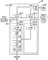
図2は、本発明によるITIの軽減を組み込む磁気記録システム200の一部の概略構成図である。図2は、読み取り動作中のITIの軽減のための磁気記録システム200の構成を示す。図2に示されるように、磁気記録システム200は、ハードディスクコントローラ(HDC)210およびリード・チャネル(RC)250を含む。リード・チャネル250は、読み取りデータ経路(RDP)260−Rおよび書き込みデータ経路(WDP)260−Wを含む。既に示されたように、書き込みデータ経路260−Wは、所与のトラックNに隣接するトラックN−1およびN+1などの1つまたは複数の隣接するトラックに関するキャンセル・データを、読み取りデータ経路260−RのITI軽減回路280に伝達するために本発明によって使用される。キャンセル・データは、磁気媒体から読み取りデータ経路260−Rによって取得される媒体データと実質的に同時にITI軽減回路280に与えられる。
FIG. 2 is a schematic block diagram of a portion of a
概して、RDP−アナログ・ブロック290は、交流結合減衰器(ac−coupling,attenuator)(ACC)、適応制御、ベースライン補償(baseline compensation)、磁気抵抗非対称(MRA)補償(magneto−resist asymmetric(MRA) compensation)、サーマル・アスペリティ(thermal asperity)(TA)検出を備える可変利得増幅器(VGA)、デジタル信号処理のための適応制御を備える連続時間フィルタ(CTF)、およびアナログ・デジタル・コンバータ(ADC)などのいくつかのアナログ・コンポーネントを含む。概して、サーマル・アスペリティは、読み取りヘッドが、磁気材料が存在するディスク・プラッタの平面の上に隆起しているその磁気材料の一部に衝突するときに発生し、信号の振幅を実質的に大きくする。サーマル・アスペリティ検出ブロックは、知られている方法で、そのような磁気材料部分を特定し、それらを補償するように試みる。
In general, the RDP-
次いで、デジタル化された信号が、信号を等化するデジタル有限インパルス応答(DFIR)フィルタ285によってフィルタリングされる。DFIR285は、フィルタリングされた出力をITI軽減回路280に提供する。次に、ITI軽減回路280によって生成されたITIが打ち消された信号が、ビタビ検出器と、低密度パリティ検査復号器などの復号器とを含む反復復号ブロック270に与えられる。読み取りデータ経路260−Rは、所与のトラックNに関する復号されたデータをハードディスクコントローラ210に提供する。
The digitized signal is then filtered by a digital finite impulse response (DFIR)
既に示されたように、書き込みデータ経路260−Wは、概して、誤り訂正が後のデータの読み取りに対して実行され得るように、媒体に書き込まれるべきデータを符号化する機能を含む。加えて、書き込みデータ経路260−Wは、さらに、データをスクランブルし、バッファリングし、この機能は、ITIの軽減のために本発明によって利用されることができる。 As already indicated, the write data path 260-W generally includes the ability to encode the data to be written to the media so that error correction can be performed for later reading of the data. In addition, the write data path 260-W further scrambles and buffers data, and this functionality can be utilized by the present invention for ITI mitigation.
例示的なITI軽減回路280のより詳細な検討については、例えば、参照により本明細書に援用される、「Systems and Methods for Inter−Track Interference Compensation」と題された、2011年7月19日に出願された米国特許出願第13/186,174号(代理人整理番号AGERE−022110)を参照されたい。本発明によるITIの軽減のためのいくつかの例示的な技術が、図5〜10に関連して以下でさらに検討される。例えば、本発明のさまざまな実装は、ITIの軽減を用いるかまたは用いない、磁気媒体295の直接読み取りをサポートする。加えて、本発明の別の実装は、少なくとも片側のITIの軽減を用いるオンザフライ(OTF)またはリアルタイムの読み取りをサポートする。本発明のさらに別の実装は、両側のITIの軽減まで用いたオフラインの読み取りをサポートする。
For a more detailed review of an exemplary
本発明は、Y−平均された(Y−Averaged)データなどの後処理されたDFIRデータのITIの軽減、および/またはITIを軽減されたデータのY−平均などの、ITIを軽減されたDFIRデータの後処理もサポートする。例えば、Y−平均されたデータのITIの軽減は、複数の読み取りにわたるY−平均を取得することと、次いで、Y−平均されたサンプルを用いてITIの軽減および復号を実行することとを含む。同様に、ITIを軽減されたデータのY−平均は、セクタを読み取ることと、現在の読み取ったセクタを用いてITIの軽減および任意的に復号を実行することと、複数の読み取りからのITIを軽減されたサンプルを用いてY−平均を得ることとを含み、その後に次のセクタの読み取りが続き、以下同様である。 The present invention provides ITI reduced DFIR, such as ITI reduction of post-processed DFIR data, such as Y-Averaged data, and / or Y-average of ITI reduced data. Supports post-processing of data. For example, ITI mitigation of Y-averaged data includes obtaining a Y-average over multiple readings, and then performing ITI mitigation and decoding using the Y-averaged samples. . Similarly, the Y-average of data with ITI mitigation is to read a sector, perform ITI mitigation and optional decoding with the current read sector, and calculate ITI from multiple reads. Using the reduced sample to obtain a Y-average, followed by a reading of the next sector, and so on.
図2に示されるように、ハードディスクコントローラ210は、それぞれ、読み取りデータ経路(RDP)260−Rおよび書き込みデータ経路(WDP)260−Wの対応する長レイテンシ・インターフェース(long latency interface)(LLI)255−R、255−Wと通信するための例示的な長レイテンシ・インターフェース(LLI)240−R、240−Wを含む。
As shown in FIG. 2, the
ハードディスクコントローラ210は、ダイナミックランダムアクセスメモリ(DRAM)220などの外部ダブルデータレート(DDR)デバイスと通信するためのダブルデータレート(DDR)PHYインターフェース230も含む。キャンセル・データは、例えば、外部DRAM220、またはスタティックランダムアクセスメモリ(SRAM)もしくはフラッシュメモリなどの別の不揮発性メモリに記憶され得る。例示的なDRAM220は、磁気媒体100(図1)または磁気媒体295(図2)の1つまたは複数のトラックに関するキャンセル・データを記憶することができる。例えば、記憶されるキャンセル・データの量は、現在読み取られているトラックに関するトラック間隔(track spacing)に応じて決まる可能性がある。例示的なDRAM220は、DRAMに記憶される必要があるデータの量を削減するために1つまたは複数のセクタ(例えば、以前の読み取り動作中に正常に再生されることができなかったセクタ)だけに関するキャンセル・データを記憶することもできる。
The
サイドトラック・データとも呼ばれるキャンセル・データは、当業者に明らかであろうように、いくつかの例示的なフォーマットを有する可能性がある。概して、例示的なキャンセル・データは、書き込まれた媒体の波形に対応する符号化された媒体データ、またはハードディスクコントローラ210によって通常供給される符号化されていないユーザ・データを含み得る。概して、例示的な媒体データ・フォーマットは、低密度パリティ検査(LDPC)オーバヘッド、ランレングス制限(run−length limited)(RLL)符号化オーバヘッド、および誤り検出符号(EDC)オーバヘッドを含む符号化されたデータを含む。図3および4は、媒体データを処理するための異なる実施形態を組み込むリード・チャネル250の代替的な実装250’および250’’をそれぞれ示す。図3および4において、ランレングス制限および誤り検出符号符号器および復号器機能ならびにスクランブラ機能は、「ESR」(すなわち、誤り検出符号、スクランブラ、およびRLL)とラベル付けされる。
Cancel data, also referred to as sidetrack data, may have several exemplary formats, as will be apparent to those skilled in the art. In general, exemplary cancellation data may include encoded media data corresponding to the waveform of the written media, or unencoded user data normally provided by
例示的な実施形態において、ITI軽減回路280は、「Y−データ(Y−Data)」と呼ばれる等化されたアナログ・デジタル・コンバータ(ADC)サンプルを処理することがさらに留意される。代替的な実施形態において、ITI軽減回路280は、本明細書では「ADCデータ」と呼ばれる生の(等化されていない)ADCサンプルを処理することができる。Y−データまたはADCデータは、例えば、媒体に書き込まれた各媒体ビット(media bit)に関する6ビットのデータである可能性がある。ADC−データまたはY−データは、磁気媒体295から読み取られ、それぞれ、ADCまたはDFIR等化器の出力で利用可能である。反復復号ブロック270は、各Y−データ・サンプルを検出された媒体データの単一のビットに、ならびに(パリティおよびその他のオーバヘッド・ビットの除去の後)検出されたユーザ・データの単一のビットに変換する。反復復号ブロック270は、例えば、よく知られているLDPC復号器を用いて具現化され得る。
It is further noted that in the exemplary embodiment,
例示的な実施形態において、書き込みデータ経路260−Wは、ITIキャンセル・データをユーザまたは媒体データ・フォーマットで表す。代替的な実施形態において、書き込みデータ経路260−Wは、ITIキャンセル・データをADCまたはY−データ・フォーマットで表し、その場合、媒体ビットごとの複数のビットが、DRAMに記憶され、HDCから書き込みデータ経路260−Wに供給される。ITI軽減回路280は、書き込みデータ経路260−Wが何を供給するかに応じて媒体データ、ADCデータ、またはY−データに基づいてITIを軽減する。HDCがITIキャンセル・データをリード・チャネルにユーザ・データ・フォーマットで提供する場合、書き込みデータ経路は、図3および4に示されるように、ユーザ・データを媒体データに変換する。
In the exemplary embodiment, write data path 260-W represents ITI cancellation data in user or media data format. In an alternative embodiment, write data path 260-W represents ITI cancellation data in ADC or Y-data format, where multiple bits per media bit are stored in DRAM and written from HDC. Provided to data path 260-W. The
DDR PHY230が追加的な費用およびシステム設計の修正なしにY−データまたはADCデータ・フォーマット(例えば、記憶された媒体ビットごとに6ビット)をサポートするのに十分な帯域幅を持たない場合、本発明のユーザまたは媒体データ・フォーマットの実装である単一ビット・フォーマットは、それでもサポートされることができることが留意される。単一ビット・フォーマットを用いると、1ビット単位の帯域幅が追加される必要があるだけである。読み取りデータは、既存の非ITIドライブのメモリに書き込まれることがさらに留意される。したがって、DDRからデータを読み取り、開示されたITIキャンセル手順で使用するためにリード・チャネルにキャンセル・データを送るために1帯域幅ビット単位が追加されるだけである。単一ビット・フォーマットを使用することによって、DRAMでITIキャンセル・データのために必要とされるストレージの量が、やはり大幅に削減される。
If
1つの例示的な実施形態において、磁気記録システム200は、ITIキャンセル・データが所与の読み取り動作のために使用されるべきかどうかを示す、例えば、METACMD[1]またはITI_GATEと呼ばれるITI制御信号またはレジスタを含む。ITI制御信号がITIキャンセル・データが所与の読み取り動作のために使用されるべきでないことを示す場合、ITI軽減回路280は、図3〜4で以下にさらに示されるように(ITIの軽減のために使用されるべきデータが存在しないので)任意的に迂回されることができる。加えて、例示的な磁気記録システム200は、例示的な実施形態において、ITIのキャンセルが1つの隣接するトラックのみに対して実行されるべきか(例えば、ITI_SIDESがITI_SIDES=0に設定される)、または2つの隣接するトラックに対して実行されるべきか(例えば、ITI_SIDESがITI_SIDES=1に設定される)を示すための、例えば、ITI_SIDESと呼ばれるモード制御信号またはレジスタを含む。概して、任意の数Nのトラックが、真ん中のトラックにITIの影響を有する可能性がある。当業者に明らかであろうように、追加的に、N個の側面のITIの軽減が、本発明にしたがってNステップで実行され得る。
In one exemplary embodiment, the
図3は、書き込みデータ経路がITI軽減回路280に示すための媒体データを生成する、図2のリード・チャネル250の代替的な実装250’の概略構成図である。図3に示されるように、例示的なリード・チャネル250’は、図2と同様にして、読み取りデータ経路360−Rと、書き込みデータ経路360−Wとを含む。読み取りデータ経路360−Rは、図2の読み取りデータ経路260−Rと同様にして実装され得る。既に示されたように、書き込みデータ経路360−Wは、キャンセル・データを、読み取りデータ経路360−RのITI軽減回路280に伝達するために本発明によって使用される。キャンセル・データは、磁気媒体から読み取りデータ経路360−Rによって取得される媒体データと実質的に同時にITI軽減回路280に与えられる。別の例示的な実施形態において、キャンセル・データは、磁気媒体から読み取りデータ経路360−Rによって取得される対応する媒体データの前または後にITI軽減回路280に与えられる。
FIG. 3 is a schematic block diagram of an
読み取りデータ経路(RDP)360−Rおよび書き込みデータ経路360−Wの長レイテンシ・インターフェース(LLI)255−R、255−Wは、それぞれ、図2と同様にして実装され得る。さらに、反復復号ブロック270およびITI軽減回路280は、図2と同様にして実装され得る。
The read data path (RDP) 360-R and write data path 360-W long latency interfaces (LLI) 255-R, 255-W can each be implemented in the same manner as in FIG. Further,
図3の例示的な実施形態において、符号化された媒体データは、書き込みデータ経路360−Wによって生成される。HDCは、ITIキャンセル・データを書き込みデータ経路にユーザ・データ・フォーマットで提供する。図3に示されるように、例示的な書き込みデータ経路360−Wは、ユーザ・データを、ITIキャンセル・データとしてITI軽減回路に提供される符号化された媒体データに符号化するESR符号器320−WおよびLDPC符号器330を含む。書き込みデータ経路は、媒体への書き込み動作中と同様の方法でユーザ・データを符号化する。 In the exemplary embodiment of FIG. 3, the encoded media data is generated by write data path 360-W. The HDC provides ITI cancellation data in the user data format to the write data path. As shown in FIG. 3, exemplary write data path 360-W encodes user data into encoded media data that is provided to the ITI mitigation circuit as ITI cancellation data. Includes W and LDPC encoder 330. The write data path encodes user data in the same way as during a write operation to the medium.
図3に示されるように、読み取りデータ経路360−RのITI軽減回路280は、ITIのキャンセルが所与の読み取り動作に関して有効化されないとき、任意的に迂回され得る。さらに、読み取りデータ経路360−RのESR符号器320−Rは、媒体データ・フォーマットが再生されるべきであるとき、任意的に迂回され得る。
As shown in FIG. 3, the
図4は、書き込みデータ経路がユーザ・データをITI軽減回路280に提供し、ITI軽減回路280がユーザ・データから媒体データを生成する、図2のリード・チャネル250の代替的な実装250’’の概略構成図である。図4に示されるように、例示的なリード・チャネル250’’は、図2と同様にして、読み取りデータ経路460−Rと、書き込みデータ経路360−Wとを含む。読み取りデータ経路460−Rは、図2の読み取りデータ経路260−Rと同様にして実装され得る。既に示されたように、書き込みデータ経路460−Wは、キャンセル・データを、読み取りデータ経路460−RのITI軽減回路280に伝達するために本発明によって使用される。キャンセル・データは、磁気媒体から読み取りデータ経路460−Rによって取得される媒体データと実質的に同時にITI軽減回路280に与えられる。別の例示的な実施形態または動作モードにおいて、キャンセル・データは、磁気媒体から読み取りデータ経路460−Rによって取得される媒体データの前または後にITI軽減回路280に与えられる。
FIG. 4 illustrates an alternative implementation 250 '' of the
読み取りデータ経路(RDP)460−Rおよび書き込みデータ経路460−Wの長レイテンシ・インターフェース(LLI)255−R、255−Wは、それぞれ、図2と同様にして実装され得る。さらに、反復復号ブロック270およびITI軽減回路280は、図2と同様にして実装され得る。
The read data path (RDP) 460-R and write data path 460-W long latency interfaces (LLI) 255-R, 255-W can each be implemented in the same manner as in FIG. Further,
図4の例示的な実施形態において、符号化された媒体データは、書き込みデータ経路460−Wによって提供されるユーザ・データからITI軽減回路280により生成される。したがって、図4に示されるように、例示的な書き込みデータ経路460−WのESR符号器420−WおよびLDPC符号器430は、ITI軽減回路280に与えられるユーザ・データによって迂回される。書き込みデータ経路460−WのESR符号器420−WおよびLDPC符号器430は、ユーザ・データが媒体に書き込まれる前に媒体データに符号化されるときは、書き込み動作中にユーザ・データによって迂回されない。
In the exemplary embodiment of FIG. 4, encoded media data is generated by
図4に示されるように、読み取りデータ経路460−RのITI軽減回路280は、ITIのキャンセルが所与の読み取り動作に関して有効化されないとき、任意的に迂回され得る。さらに、読み取りデータ経路460−RのESR符号器420−Rは、媒体データ・フォーマットが再生されるべきであるとき、任意的に迂回され得る。
As shown in FIG. 4, the
図5〜10は、いくつかの例示的な動作モードを実装するためのさまざまな構成のリード・チャネル250を示す。図5〜10において、アクティブな信号経路は、太字破線矢印を用いて示される。図5〜10に示されるように、および上で検討されたように、リード・チャネル250は、デジタル有限インパルス応答フィルタ285、ITI軽減回路280、および反復復号ブロック270を含む。
5-10 illustrate various configurations of the
加えて、図5〜10に関連して以下でさらに検討されるように、リード・チャネル250は、マルチプレクサ505、515、Y−AVG後処理ブロック510、Y−MEMメモリ・ブロック520、およびY−データを処理するためのY−MEMアドレス・ブロック530をさらに含む。
In addition, as discussed further below in connection with FIGS. 5-10, read
図5Aは、例示的な非ITI動作モードのリード・チャネル250を示す。概して、非ITIモードは、ITIの軽減が必要とされないときに(例えば、トラックの分離が十分であるときに)選択的に無効化されることを可能にし、さらに、リード・チャネル250がITIの軽減がサポートされない可能性があるレガシーシステムで使用されることを可能にする。図5Aに示されるように、ITI軽減回路280は、マルチプレクサ505を用いて迂回され、Y−AVGブロック510は、マルチプレクサ515を用いて迂回される。したがって、非ITIモードのためのアクティブな信号経路は、DFIRフィルタ285、Y−MEMブロック520、および反復復号ブロック270を含む。概して、Y−データは、Y−MEMブロック520に記憶され、次いで、復号のために反復復号ブロック270に適用される。
FIG. 5A shows an exemplary non-ITI mode of operation read
図5Bは、図5Aの例示的な非ITI動作モードに関して、いくつかのインターフェース信号を時間の関数として示す。概して、以下の図において、MEDIA信号は、何が媒体上にあるか(サーボ(servo)、フラグメント(fragment)、またはフル・セクタ(full sector))を示す。図の用語「FRG」は、セクタのフラグメントを示し、用語「FULL」は、完全なセクタを示し、用語「SERVO」は、分割セクタ(split sector)を示す(例えば、FRG5.1は、左のセクタのフラグメントであり、FRG5.2は、右のセクタのフラグメントであり、それらは、「SERVO」ラベルによって示されるように分割される)。したがって、FRG5.1とFRG5.2とが一緒にFULL5を構成する(フル・セクタが2つに分割される)。加えて、2つのRDGATEパルスが、各部分を読み取るために使用され、チャネルが、組み合わせてfull5セクタを再生する。一部の図において、用語「MEDIA(1回転目)」および「MEDIA(2回転目)」は、同じセクタが2回読まれる(ディスクが、ヘッドをもう一度そのセクタの上に持ってくるために一周しなければならない)ことを示す。 FIG. 5B shows several interface signals as a function of time for the exemplary non-ITI mode of operation of FIG. 5A. In general, in the following figures, the MEDIA signal indicates what is on the medium (servo, fragment, or full sector). The term “FRG” in the figure refers to a fragment of a sector, the term “FULL” refers to a complete sector, and the term “SERVO” refers to a split sector (eg, FRG 5.1 is Is a fragment of the sector, FRG 5.2 is a fragment of the right sector and they are split as indicated by the “SERVO” label). Therefore, FRG5.1 and FRG5.2 together constitute FULL5 (a full sector is divided into two). In addition, two RDGATE pulses are used to read each part, and the channels combine to reproduce the full5 sector. In some figures, the terms "MEDIA (first rotation)" and "MEDIA (second rotation)" read the same sector twice (because the disk brings the head over it again) I have to go around).
SVGATE信号は、(単に参照のために)サーボ・ゲート(servo gate)を示す(および、媒体上のあらゆるSERVOの上でhighである)。DARA_W信号は、(ITIキャンセル・データがチャネルに入る)書き込み経路データを示す。LEFT#は、同じ番号を有するセクタに関する左キャンセル・データを示し、つまり、LEFT#は、左のトラックに書き込まれた隣接するデータに対応する。RIGHT#は、同じ番号を有するセクタに関する右キャンセル・データを示し、つまり、RIGHT#は、右のトラックに書き込まれた隣接するデータに対応する。図1を参照すると、トラック2がデータが再生される現在のトラックである場合、トラック1およびトラック3が、それぞれ、隣接する左トラックおよび右トラックである。
The SVGATE signal indicates (for reference only) a servo gate (and is high on every SERVO on the media). The DARA_W signal indicates write path data (ITI cancel data enters the channel). LEFT # indicates left cancel data for sectors having the same number, that is, LEFT # corresponds to adjacent data written to the left track. RIGHT # indicates right cancellation data for sectors having the same number, that is, RIGHT # corresponds to adjacent data written in the right track. Referring to FIG. 1, when
RDGATE信号は、リード・ゲート(read gate)に対応し、媒体からの読み取りを示す。RDGATE信号は、各セクタおよびセクタのフラグメントの始まりにおいてアクティブである。RETRYGATE信号は、記憶されたサンプルからの(y−メモリ(y−memory)からの)再試行を示す。RETRYGATE信号は本明細書においてはITIの軽減との関連で示されるが、当業者に明らかであろうように、RETRYGATE信号は、その他の用途でも使用され得ることが留意される。 The RDGATE signal corresponds to a read gate and indicates reading from the medium. The RDGATE signal is active at the beginning of each sector and sector fragment. The RETRYGATE signal indicates a retry (from y-memory) from the stored sample. Although the RETRYGATE signal is shown herein in the context of ITI mitigation, it is noted that the RETRYGATE signal may be used in other applications as will be apparent to those skilled in the art.
本明細書において検討されるように、信号METACMD[1]は、(RDGATEまたはRETRYGATEに合わせられた)読み取りまたは再試行と一緒にITIの軽減をトリガする。図5Bは軽減を用いない通常の読み取り動作に対応するので、METACMD[1]はアクティブではない。 As discussed herein, the signal METACMD [1] triggers ITI mitigation along with a read or retry (tuned to RDGATE or RETRYGATE). Since FIG. 5B corresponds to a normal read operation without mitigation, METACMD [1] is not active.
DATA−R信号は、再生されたセクタ・データを示す(FULL#は、同じ名前の媒体のセクタに関する再生されたデータを意味する)。加えて、SECTOR_GOOD信号は、良好なセクタが再生されたことを示す(セクタが良好でないときは、追加的な処理が、セクタを再生するために実行される)。 The DATA-R signal indicates reproduced sector data (FULL # means reproduced data relating to a sector of the same name medium). In addition, the SECTOR_GOOD signal indicates that a good sector has been reproduced (if the sector is not good, additional processing is performed to reproduce the sector).
さらに、以下の図のうちの1つまたは複数において、以下の表記が使用される。
avg(data1,data2)は、同じデータの2回の読み取り動作からのデータのビットごとの平均を示し、媒体上に記憶された各ビットに関して、対応するY−サンプル(Y−sample)data1およびdata2が平均される。代替的な実装においては、ADCサンプルが平均される。
decode(data)は、LDPC復号動作(Y−データから媒体またはユーザ・ビットに変換されるデータ再生)を示し、Y−データは、例えば、6ビットを用いて表される。
iti(left,data)は、「data」内の主トラック信号から左の隣接するトラックによってもたらされたITIを除去することを示す。
iti(left,right,data)は、「data」内の主トラック信号から左右両方の隣接するトラックによってもたらされたITIを除去することを示す。
Further, the following notation is used in one or more of the following figures.
avg (data1, data2) indicates the average per bit of data from two reading operations of the same data, and for each bit stored on the medium, the corresponding Y-sample data1 and data2 Is averaged. In an alternative implementation, the ADC samples are averaged.
“decode (data)” indicates an LDPC decoding operation (reproduction of data converted from Y-data to a medium or user bits), and Y-data is expressed using, for example, 6 bits.
iti (left, data) indicates to remove the ITI caused by the left adjacent track from the main track signal in "data".
iti (left, right, data) indicates to remove the ITI caused by both the left and right adjacent tracks from the main track signal in "data".
図6Aは、例示的な後処理(非ITI)動作モードのリード・チャネル250を示す。図6Aに示されるように、ITI軽減回路280は、マルチプレクサ505を用いて迂回される。したがって、非ITIモードのためのアクティブな信号経路は、DFIRフィルタ285、(マルチプレクサ515を用いて選択される)Y−AVGブロック510、Y−MEMブロック520、および反復復号ブロック270を含む。Y−MEMアドレス・ブロック530は、知られている方法でY−MEMブロック520の選択を制御する。概して、所与のセクタからの記憶されたデータの最初の読み取りに関するY−データが、Y−MEMブロック520に記憶され、次に、そのセクタからのデータのその後の再読み取りに関するすべてのサンプルが、Y−AVGブロック510によってフィードバック経路540を用いてY−MEMブロック520の内容と合併される、つまり、平均される。所与のセクタは、その所与のセクタからの記憶されたデータが正常な復号動作によって示されるように正常に読み取られるまで、Y−MEMブロック520の内容が繰返しのたびに更新されるようにして複数回読み取られる可能性がある。Y−MEMブロック520の出力は、復号のために反復復号ブロック270にやはり適用される。
FIG. 6A shows the
図6Bは、図6Aの例示的な後処理(非ITI)動作モードに関して、いくつかのインターフェース信号を時間の関数として示す。例示的な実施形態において実行される後処理は、記憶されたデータを2回読み取り、図6Bに示される2回の読み取り動作で読み取られたデータのビットごとの平均を実行することなどによる、ITIの軽減を用いない平均読み取り(Average Read)を含む。当業者に明らかであろうように、平均は、任意の回数の読み取り動作に対して実行され得る。第2の読み取りおよび平均が、データが再生され得るように雑音を十分に削減するので、ITIの軽減が必要とされないことが留意される。図6Bに示されるように、SECTOR_GOOD信号が、第3のセクタ上の第1の通過に関しては存在しないが、第3のセクタ上の第2の通過の後には存在する。セクタFULL3は、第1の読み取り中に読み取られ、次いで、反復復号器に渡され、復号されたセクタが、DATA_Rバスに渡されることが留意される。セクタが誤りなしに正常に復号されなかったので、SECTOR_GOOD信号は、アサートされない。第2の回転で、第2の読み取りの後、2つの読み取りのY−データが平均され、Y−平均されたデータが、反復復号ブロックに渡され、反復復号ブロックが、セクタを正常に復号する。 FIG. 6B shows some interface signals as a function of time for the exemplary post-processing (non-ITI) mode of operation of FIG. 6A. Post-processing performed in the exemplary embodiment includes ITI, such as by reading stored data twice and performing a bit-by-bit average of the data read in the two read operations shown in FIG. 6B. Average Read without any reduction. As will be apparent to those skilled in the art, averaging can be performed for any number of read operations. It is noted that the ITI mitigation is not required because the second reading and averaging sufficiently reduce the noise so that the data can be recovered. As shown in FIG. 6B, the SECTOR_GOOD signal is not present for the first pass on the third sector, but is present after the second pass on the third sector. Note that sector FULL3 is read during the first read and then passed to the iterative decoder, and the decoded sector is passed to the DATA_R bus. The SECTOR_GOOD signal is not asserted because the sector was not successfully decoded without error. In the second rotation, after the second read, the Y-data of the two reads is averaged, the Y-averaged data is passed to the iterative decoding block, and the iterative decoding block successfully decodes the sector. .
図7Aは、例示的なリアルタイムITI動作モードのリード・チャネル250を示す。概して、ITIの軽減が、データ転送速度で実行され、あらゆるセクタに対して任意的に実行され得る。図7Aの実施形態において、ITIの軽減は、スループットへの影響を少なくするために(例えば、例示的なモード制御信号またはレジスタ、ITI_SIDESによって示されるように)1つの隣接するトラックに対してのみ実行される。ITIキャンセル・データは、図2に関連して上で検討されたように、書き込みデータ経路260−W(図2)から得られる。図7Aに示されるように、ITI軽減回路280は、マルチプレクサ505によってアクティブな信号経路に置かれ、Y−AVGブロック510は、マルチプレクサ515によって迂回される。したがって、リアルタイムITIモードのためのアクティブな信号経路は、DFIRフィルタ285、ITI軽減回路280、Y−MEMブロック520、および反復復号ブロック270を含む。概して、ITI軽減回路280のITIを補正された出力は、Y−MEMブロック520に記憶され、次いで、復号のために反復復号ブロック270に適用される。
FIG. 7A shows an exemplary real-time ITI mode of operation read
図7Bは、図7Aの例示的なリアルタイムITI動作モードに関して、いくつかのインターフェース信号を時間の関数として示す。本明細書において検討されるように、例示的なリアルタイムITI動作モードは、ITIの軽減が、RDGATE信号と同時にMETACMD[1]信号をアサートすることによって選択的に有効化されることを可能にする。(OTFまたは再試行動作のいずれかに関してITI_SIDES=0)。 FIG. 7B shows some interface signals as a function of time for the exemplary real-time ITI mode of operation of FIG. 7A. As discussed herein, an exemplary real-time ITI mode of operation allows ITI mitigation to be selectively enabled by asserting the METACMD [1] signal simultaneously with the RDGATE signal. . (ITI_SIDES = 0 for either OTF or retry operation).
RDGATE信号はセクタ1、2、3、4、5、6、7が媒体から読み取られることを示す。DATA_W信号は、ITIの軽減がセクタ3、4、および6に対して左側のトラックを用いて実行されることを示す。METACMD[1]信号は、(RDGATEまたはRETRYGATEに合わせられた)読み取りまたは再試行と一緒にITIの軽減をトリガする。セクタ1、2、5、および7は、METACMD[1]信号が関連するRDGATEとともにアサートされないので、通常通りに処理されることが留意される。
The RDGATE signal indicates that
両側のITI動作モードは、図10Aから10Cに関連して以下でさらに検討されることが留意される。 It is noted that the bilateral ITI mode of operation is discussed further below in connection with FIGS. 10A-10C.
図8Aは、例示的なITI軽減付きの後処理動作モードのリード・チャネル250を示す。概して、ITI軽減付きの後処理モードは、後処理されたY−データに対してITIの軽減を実行する。図8Aに示されるように、ITI軽減回路280は、マルチプレクサ505を用いて選択的にアクティブな信号経路に置かれ、Y−AVGブロック510は、マルチプレクサ515を用いてアクティブな信号に置かれる。したがって、ITI軽減付きの後処理モードのためのアクティブな信号経路は、DFIRフィルタ285、ITI軽減回路280、Y−AVGブロック510、Y−MEMブロック520、および反復復号ブロック270を含む。Y−MEMアドレス・ブロック530は、知られている方法でY−MEMブロック520の選択を制御する。
FIG. 8A shows the
概して、所与のセクタの最初の読み取りに関して、ITI軽減回路280およびY−AVGブロック510は迂回され、Y−データがY−MEMブロック520に記憶される。そのセクタのその後のM回の再読み取りに関して、個々の読み取りからの新しいYサンプルは、Y−AVGブロック510によってフィードバック経路540を用いてY−MEMブロック520の内容と合併される(すなわち、平均される)。所与のセクタは、そのセクタが正常に読み取られるまで、Y−MEMブロック520の内容が繰返しのたびに更新されるようにして複数回読み取られる可能性がある。M+1回目の読み取り動作およびY−平均動作の完了の後、Y−MEMブロック520は、同じセクタのM+1回の読み取り動作からのY−データの平均を含む。Y−MEMブロック520の出力は、復号のために反復復号ブロック270にやはり適用される。
In general, for the first read of a given sector,
後処理されたY−データを用いて、事前に定義された回数(M+1回)の再読み取りの後でセクタが正常に読み取れない場合、後処理されたデータに対してITIの軽減を実行するために、ITIの軽減が有効化され得る。ITIの軽減を実行するための指示が、RETRYGATEとMETACMD[1]の組み合わされたシグナリングによって(または、RETRYGATEとITI_GATEの組み合わされたシグナリングによって)開始される。このモードにおいては、Y−データが、マルチプレクサ502の制御の下で、フィードバック経路545を用いてY−MEMブロック520からITI軽減回路280に適用される。RETRYGATE信号は、Y−データが、媒体のセクタを読み取ることによって得られないが、前の読み取り動作からのYサンプルを含むY−MEMブロックを読み取ることによって得られることを示す。(例示的なITI_SIDES制御語の値に基づいて片側または両側の)ITIキャンセル・データは、図2に関連して上で検討されたように、書き込みデータ経路260−W(図2)から得られる。加えて、Y−AVGブロック510は、そのとき、マルチプレクサ515を用いて迂回され、したがって、後処理され、次いで打ち消されたデータが、反復復号ブロック270による復号の前にY−MEMブロック520に記憶されることができる。
Using post-processed Y-data to perform ITI mitigation on post-processed data if the sector cannot be read successfully after a predefined number of times (M + 1) re-read In addition, ITI mitigation can be enabled. An indication to perform ITI mitigation is initiated by RETRYGATE and METACMD [1] combined signaling (or by RETRYGATE and ITI_GATE combined signaling). In this mode, Y-data is applied from the Y-
さらなる変形形態において、平均の再読み取り動作の回数は、動的に決定され得る(または事前に定義された条件が発生すると終了され得る)。平均動作のたびに、平均されたデータが復号器にプッシュされるときに、データが復号され、復号の品質に関する1つまたは複数の測定基準が生成される。例えば、1つの例示的な品質の測定基準は、ビット誤りの数を含み得る。1つの例示的な実装において、平均手順は、ビット誤りの数が減少するまで継続され得る。ビット誤りの数が横ばいになる(すなわち、さらなる平均がもはや助けにならない可能性がある)場合、ITIの軽減が実行されることができる。同様に、ITIの軽減のその後の使用も、動的に決定され得る。ITIの軽減動作が実行されるとき、(潜在的に、ビット誤りに関して上で検討された同じ例を用いて)データおよび測定基準が計算され、コントローラに送信され、コントローラが、再生が実現されると直ちに終了する可能性がある。この場合、信号ITI_SIDESが片側のキャンセルのみを実行するように調整され、それぞれの側が、再生が成功するまで、各ステップの後に分析された測定基準/データを用いて1つずつ実行される。 In a further variation, the average number of reread operations may be determined dynamically (or terminated when a pre-defined condition occurs). For each averaging operation, when the averaged data is pushed to the decoder, the data is decoded and one or more metrics regarding the quality of the decoding are generated. For example, one exemplary quality metric may include the number of bit errors. In one exemplary implementation, the averaging procedure may be continued until the number of bit errors is reduced. If the number of bit errors levels off (ie, further averaging may no longer help), ITI mitigation can be performed. Similarly, subsequent use of ITI mitigation can be determined dynamically. When an ITI mitigation operation is performed, data and metrics are calculated and transmitted to the controller (potentially using the same example discussed above with respect to bit errors), and the controller implements playback. And may end immediately. In this case, the signal ITI_SIDES is adjusted to perform only one-side cancellation, and each side is executed one by one using the metric / data analyzed after each step until playback is successful.
図8Bは、図8Aの例示的な片側のITI軽減付きの後処理動作モード(ITI_SIDES=0)に関して、いくつかのインターフェース信号を時間の関数として示す。例示的な実施形態において実行される後処理は、図8Bに示される2回の読み取りの平均などの、片側のITIの軽減を用いる平均読み取りを含む。当業者に明らかであろうように、平均は、任意の回数の読み取り動作に対して実行され得る。読み取りは、第1の読み取り動作または第2の読み取り動作がSECTOR_GOOD信号を有する場合、停止され得ることが留意される。DATA_R信号に関して、図8Bの第1の「FULL3」は、decode(avg(read1,read2))を含み、第2の「FULL3」は、decode(iti(left,avg(read1,read2)))を含むことがさらに留意される。セクタFULL3は、第1の読み取り中に読み取られ、次いで、反復復号器に渡され、復号されたセクタが、DATA_Rバスに渡されることが留意される。セクタが誤りなしに正常に復号されなかったので、SECTOR_GOOD信号は、アサートされない。第2の回転で、第2の読み取りの後、2つの読み取りのY−データが平均され、Y−平均されたデータが、反復復号ブロックに渡され、復号されたセクタが、DATA_Rバスに渡される。セクタが誤りなしに正常に復号されなかったので、SECTOR_GOOD信号は、アサートされない。次に、RETRYGATEおよびMETACMD[1]信号が、本発明によるITIのキャンセルを開始して、Y−平均されたデータを処理し、主トラックのセクタ3に隣接する左トラック(LEFT3)に関するキャンセル・データを用いてITIを軽減する。このキャンセル・データLEFT3は、DATA_Wバスを用いて書き込みデータ経路で前もって与えられた。結果が、反復復号ブロックに渡され、反復復号ブロックが、復号されたセクタを生成する。復号されたセクタは、DATA_Rバスに渡される。このセクタが誤りなしに正常に復号されたので、SECTOR_GOOD信号が、アサートされる。
FIG. 8B shows some interface signals as a function of time for the exemplary one-sided post-processing operating mode with ITI mitigation (ITI_SIDES = 0) of FIG. 8A. The post-processing performed in the exemplary embodiment includes an average reading with one-sided ITI mitigation, such as the average of two readings shown in FIG. 8B. As will be apparent to those skilled in the art, averaging can be performed for any number of read operations. It is noted that the reading may be stopped if the first reading operation or the second reading operation has a SECTOR_GOOD signal. Regarding the DATA_R signal, the first “FULL3” in FIG. 8B includes decode (avg (read1, read2)), and the second “FULL3” includes decode (iti (left, avg (read1, read2))). It is further noted that including. Note that sector FULL3 is read during the first read and then passed to the iterative decoder, and the decoded sector is passed to the DATA_R bus. The SECTOR_GOOD signal is not asserted because the sector was not successfully decoded without error. In the second rotation, after the second read, the Y-data of the two reads is averaged, the Y-averaged data is passed to the iterative decoding block, and the decoded sector is passed to the DATA_R bus. . The SECTOR_GOOD signal is not asserted because the sector was not successfully decoded without error. The RETRYGATE and METACMD [1] signals then initiate ITI cancellation according to the present invention to process the Y-averaged data and cancel data for the left track (LEFT3) adjacent to
図8Cは、図8Aの例示的な自動的な両側のITI軽減付きの後処理動作モード(ITI_SIDES=1)に関して、いくつかのインターフェース信号を時間の関数として示す。例示的な実施形態において実行される後処理は、図8Cに示される2回の読み取りの平均などの、自動的な両側のITIの軽減を用いる平均読み取りを含む。当業者に明らかであろうように、平均は、任意の回数の読み取り動作に対して実行され得る。読み取りは、第1の読み取り動作または第2の読み取り動作がSECTOR_GOOD信号を有する場合、または第1のITI RETRYがSECTOR_GOOD信号を有するとき、停止され得ることが留意される。DATA_R信号に関して、図8Cの第1の「FULL3」は、decode(avg(read1,read2))を含み、第2の「FULL3」は、decode(iti(left,right,avg(read1,read2)))を含むことがさらに留意される。セクタFULL3は、第1の読み取り中に読み取られ、次いで、反復復号器に渡されることが留意される。復号されたセクタが、DATA_Rバスに渡される。セクタが誤りなしに正常に復号されなかったので、SECTOR_GOOD信号は、アサートされない。第2の回転で、第2の読み取りの後、2つの読み取りのY−データが平均され、Y−平均されたデータが、反復復号ブロックに渡される。復号されたセクタが、DATA_Rバスに渡される。セクタが誤りなしに正常に復号されなかったので、SECTOR_GOOD信号は、アサートされない。次に、(ITI_Sides=1として)RETRYGATEおよびMETACMD[1]信号が、自動的な両側のITI軽減動作モードを開始して、Y−平均されたデータを処理し、主トラックのセクタ3に隣接する左トラック(LEFT3)と右トラック(RIGHT3)の両方に関するキャンセル・データを用いてITIを軽減する。このキャンセル・データLEFT3およびRIGHT3は、DATA_Wバスを用いて書き込みデータ経路で前もって与えられた。組み合わされた結果が、反復復号ブロックに渡され、反復復号ブロックが、復号されたセクタを生成する。復号されたセクタが、DATA_Rバスに渡される。このセクタが誤りなしに正常に復号されたので、SECTOR_GOOD信号が、アサートされる。
FIG. 8C shows some interface signals as a function of time for the exemplary automatic two-sided post-processing operating mode with ITI mitigation (ITI_SIDES = 1) of FIG. 8A. The post-processing performed in the exemplary embodiment includes an average reading with automatic two-sided ITI mitigation, such as the average of two readings shown in FIG. 8C. As will be apparent to those skilled in the art, averaging can be performed for any number of read operations. It is noted that reading may be stopped when the first reading operation or the second reading operation has a SECTOR_GOOD signal, or when the first ITI RETRY has a SECTOR_GOOD signal. Regarding the DATA_R signal, the first “FULL3” in FIG. 8C includes decode (avg (read1, read2)), and the second “FULL3” includes decode (iti (left, right, avg (read1, read2)). Is further noted. Note that sector FULL3 is read during the first read and then passed to the iterative decoder. The decoded sector is passed to the DATA_R bus. The SECTOR_GOOD signal is not asserted because the sector was not successfully decoded without error. In the second rotation, after the second reading, the Y-data of the two readings is averaged and the Y-averaged data is passed to the iterative decoding block. The decoded sector is passed to the DATA_R bus. The SECTOR_GOOD signal is not asserted because the sector was not successfully decoded without error. Next, the RETRYGATE and METACMD [1] signals (with ITI_Sides = 1) initiate an automatic ITI mitigation mode on both sides to process the Y-averaged data and are adjacent to
図8Dは、ITIの軽減が片側ずつ実行される(ITI_SIDES=0)、図8Aの例示的な両側のITI軽減付きの後処理動作モードに関して、いくつかのインターフェース信号を時間の関数として示す。例示的な実施形態において実行される後処理は、図8Dに示される2回の読み取りの平均などの、両側のITIの軽減を(片側ずつ)用いる平均読み取りを含む。当業者に明らかであろうように、やはり、平均は、任意の回数の読み取り動作に対して実行され得る。読み取りは、いつでもSECTOR_GOOD信号が検出されるときに停止され得ることが留意される。DATA_R信号に関して、図8Dの下半分の第1の「FULL3」は、decode(read1)を含み、第2のFULL3は、decode(avg(read1,read2))を含み、第3の「FULL3」は、decode(iti(left,avg(read1,read2)))を含み、第4の「FULL3」は、decode(iti(left,right,avg(read1,read2)))を含むことがさらに留意される。セクタFULL3は、第1の読み取り中に読み取られ、次いで、反復復号器に渡されることが留意される。復号されたセクタが、DATA_Rバスに渡される。セクタが誤りなしに正常に復号されなかったので、SECTOR_GOOD信号は、アサートされない。第2の回転で、第2の読み取りの後、2つの読み取りのY−データが平均され、Y−平均されたデータが、反復復号ブロックに渡される。復号されたセクタが、DATA_Rバスに渡される。セクタが誤りなしに正常に復号されなかったので、SECTOR_GOOD信号は、アサートされない。次に、(ITI_Sides=0として)第1のRETRYGATEおよびMETACMD[1]信号が、両側のITI軽減動作モード(ただし片側ずつ)を開始して、Y−平均されたデータを処理し、主トラックのセクタ3に隣接する左トラック(LEFT3)に関するキャンセル・データを用いてITIを軽減する。このキャンセル・データLEFT3は、DATA_Wバスを用いて書き込みデータ経路で前もって与えられた。ITIのキャンセルの結果が、反復復号ブロックに渡され、反復復号ブロックが、復号されたセクタを生成する。復号されたセクタが、DATA_Rバスに渡される。このセクタが誤りなしに正常に復号されなかったので、SECTOR_GOOD信号は、アサートされない。(ITI_Sides=0として)RETRYGATEおよびMETACMD[1]信号の第2の組が、主トラックのセクタ3に隣接する右トラック(RIGHT3)に関するキャンセル・データを用いてITIの軽減を開始する。このキャンセル・データRIGHT3は、DATA_Wバスを用いて書き込みデータ経路で前もって与えられた。次に、組み合わされた結果が、反復復号ブロックに渡され、反復復号ブロックが、復号されたセクタを生成する。復号されたセクタが、DATA_Rバスに渡される。このセクタが誤りなしに正常に復号されたので、SECTOR_GOOD信号が、アサートされる。
FIG. 8D shows some interface signals as a function of time for the exemplary two-sided post-processing operating mode with ITI mitigation in FIG. 8A where ITI mitigation is performed one side at a time (ITI_SIDES = 0). The post-processing performed in the exemplary embodiment includes an average reading using bilateral ITI mitigation (one side at a time), such as the average of two readings shown in FIG. 8D. Again, as will be apparent to those skilled in the art, averaging can be performed for any number of read operations. It is noted that the reading can be stopped whenever the SECTOR_GOOD signal is detected. Regarding the DATA_R signal, the first “FULL3” in the lower half of FIG. 8D includes decode (read1), the second FULL3 includes decode (avg (read1, read2)), and the third “FULL3” is , Decode (iti (left, avg (read1, read2))), and the fourth “FULL3” further includes decode (iti (left, right, avg (read1, read2))). . Note that sector FULL3 is read during the first read and then passed to the iterative decoder. The decoded sector is passed to the DATA_R bus. The SECTOR_GOOD signal is not asserted because the sector was not successfully decoded without error. In the second rotation, after the second reading, the Y-data of the two readings is averaged and the Y-averaged data is passed to the iterative decoding block. The decoded sector is passed to the DATA_R bus. The SECTOR_GOOD signal is not asserted because the sector was not successfully decoded without error. Next, the first RETRYGATE and METACMD [1] signals (with ITI_Sides = 0) start the ITI mitigation mode on both sides (but one side at a time) to process the Y-averaged data and ITI is mitigated using cancellation data for the left track (LEFT3) adjacent to
図9Aは、例示的な後処理付きのITI軽減動作モードのリード・チャネル250を示す。この構成において、後処理付きのITI軽減モードは、最初にITIの軽減を実行し、次にY−データの後処理を実行する。図9Aに示されるように、ITI軽減回路280は、マルチプレクサ505を用いて選択的にアクティブな信号経路に置かれ、Y−AVGブロック510は、マルチプレクサ515を用いてアクティブな信号に置かれる。したがって、後処理付きのITI軽減モードのためのアクティブな信号経路は、DFIRフィルタ285、ITI軽減回路280、Y−AVGブロック510、Y−MEMブロック520、および反復復号ブロック270を含む。Y−MEMアドレス・ブロック530は、知られている方法でY−MEMブロック520の選択を制御する。
FIG. 9A shows the
図9Aの実施形態において、ITIの軽減は、例えば、例示的なモード制御信号またはレジスタ、ITI_SIDESと、(ITIの軽減をバイパスする、すなわち「まったく実行しない」ための)METACMD[1]とによって示されるように、所与の読み取り動作に対して、どちらかの隣接するトラックもしくは両方の隣接するトラックに対して実行されるか、またはまったく実行されない。ITIキャンセル・データは、図2に関連して上で検討されたように、書き込みデータ経路260−W(図2)から得られる。図9Aに示されるように、サンプルの第1の組に関して、ITI軽減回路280は、マルチプレクサ505によってアクティブな信号経路に置かれ、Y−AVGブロック510は、マルチプレクサ515によって迂回され、ITIを補正されたデータが、Y−MEMブロック520および反復復号ブロック270に送信される。
In the embodiment of FIG. 9A, ITI mitigation is indicated, for example, by an exemplary mode control signal or register, ITI_SIDES, and METACMD [1] (to bypass ITI mitigation, ie, “do not execute at all”). As can be seen, for a given read operation, it is performed on either adjacent track, both adjacent tracks, or not at all. ITI cancellation data is obtained from the write data path 260-W (FIG. 2), as discussed above in connection with FIG. As shown in FIG. 9A, for the first set of samples,
加えて、すべての残りのITIを補正されたサンプルが、Y−AVGブロック510によってフィードバック経路540を用いてY−MEMブロック520の内容と合併される(すなわち、平均される)。所与のセクタは、そのセクタが正常に読み取られるまで、Y−MEMブロック520の内容が繰返しのたびに更新されるようにして複数回読み取られる可能性がある。Y−MEMブロック520の出力は、復号のために反復復号ブロック270にやはり適用される。
In addition, all remaining ITI corrected samples are merged (ie, averaged) with the contents of Y-
図9Bは、図9Aの例示的な後処理付きのITI軽減動作モードに関して、いくつかのインターフェース信号を時間の関数として示す。例示的な実施形態において実行される後処理は、ITIを軽減されたデータの平均を含む。当業者に明らかであろうように、やはり、平均は、任意の回数の読み取り動作に対して実行され得る。概して、このプロセスは、媒体を2回読み取ることを含む。媒体を読み取るたびに、ITIが軽減され、その結果が、前に計算された/記憶された結果と平均される。例えば、2回の読み取り動作に対する平均に関して、プロセスは、媒体から目標のセクタを読み取ることと、読み取られたデータに対してITIの軽減を実行すること(例えば、左の隣接するトラックからのITIが軽減される)と、結果を記憶すること(すなわち、1組のサンプルの平均を記憶する)と、媒体295から同じ目標のセクタを再び読み取ることと、読み取られたデータに対してITIの軽減を実行すること(例えば、右の隣接するトラックからのITIが軽減される)と、第2のITIを軽減されたデータを記憶されたデータと平均すること(ITIが打ち消されたデータの平均を生じる)とを含む。これは、avg(iti(first_read),iti(second_read))=(iti(read1)+iti(read2))/2.0と表され得る。2回の読み取り中に、同じ隣接するトラックからのITIが代替的な動作モードで軽減された可能性があることが留意される。
FIG. 9B shows several interface signals as a function of time for the exemplary post-processed ITI mitigation mode of operation of FIG. 9A. The post-processing performed in the exemplary embodiment includes an average of the ITI mitigated data. Again, as will be apparent to those skilled in the art, averaging can be performed for any number of read operations. In general, this process involves reading the media twice. Each time the media is read, the ITI is reduced and the result is averaged with the previously calculated / stored result. For example, for an average over two read operations, the process reads the target sector from the media and performs ITI mitigation on the read data (eg, ITI from the left adjacent track Reduced), storing the results (ie, storing the average of a set of samples), re-reading the same target sector from
図9Aおよび9Bの例示的な後処理付きのITI軽減動作モードは片側のITIの軽減に関して示されているが、本明細書において検討されるように、および当業者に明らかであろうように、N個の側面のITIの軽減が可能であることが留意される。 Although the exemplary post-processed ITI mitigation mode of operation of FIGS. 9A and 9B is shown with respect to unilateral ITI mitigation, as discussed herein and as will be apparent to those skilled in the art, It is noted that N side ITI reduction is possible.
図10Aは、例示的な両側のITI動作モードのリード・チャネル250を示す。ITIキャンセル・データは、図2に関連して上で検討されたように、書き込みデータ経路260−W(図2)から得られる。最初に、片側のITIの軽減が、図7Aと同様にして実行される(すなわち、1つの隣接するトラックに対するITIの軽減)。図10Aに示されるように、ITI軽減回路280は、マルチプレクサ505によってアクティブな信号経路に置かれ、Y−AVGブロック510は、マルチプレクサ515によって迂回される。したがって、リアルタイムITIモードのためのアクティブな信号経路は、DFIRフィルタ285、ITI軽減回路280、Y−MEMブロック520、および反復復号ブロック270を含む。概して、ITI軽減回路280のITIを補正された出力は、Y−MEMブロック520に記憶され、次いで、復号のために反復復号ブロック270に適用される。
FIG. 10A shows an exemplary two-sided ITI mode of operation read
第2の隣接するトラックに対するITIの軽減を実行するために、Y−MEMブロック520からのY−データが、retrygate信号の制御の下でかまたは自動的にかのいずれかで、フィードバック経路545と、マルチプレクサ502による適切な選択とを用いてITI軽減ブロック280に適用される。このようにして、データは、(側面の数に関わらず)媒体の1回の読み取りがデータの1つのセクタを生成するように、復号器270に一度だけ渡される。したがって、retrygate信号によって制御されるとき、2つのイベント(1回の媒体の読み取りおよび1回の再試行)が、データの2つのセクタを生成するか、または(自動モードにおいて)1つのイベント(媒体の読み取り)が、データの1つのセクタを生成する。ITIキャンセル・データが、他方の隣接するトラックに関して、図2に関連して上で検討されたように書き込みデータ経路260−W(図2)から得られる。ITI軽減回路280は、マルチプレクサ505によってアクティブな信号経路に残り、Y−AVGブロック510は、マルチプレクサ515によってやはり迂回される。したがって、リアルタイムITIモードのためのアクティブな信号経路は、DFIRフィルタ285、ITI軽減回路280、Y−MEMブロック520、および反復復号ブロック270を含む。概して、ITI軽減回路280のITIを補正された出力は、Y−MEMブロック520に記憶され、次いで、復号のために反復復号ブロック270に適用される。このようにして、両側のITI動作モードは、磁気媒体の単一の読み取りのみによって両方の隣接するトラックに関するITIの軽減を可能にする。
In order to perform ITI mitigation for the second adjacent track, the Y-data from the Y-
図10Bは、2つの片側のITIのキャンセルが続けてトリガされる、図10Aの例示的な両側のITI動作モードに関して、いくつかのインターフェース信号を時間の関数として示す。例示的な両側のITI動作モードは、ITIの軽減が2つの隣接するトラックに対して実行されることを可能にする(ITI_SIDES=0、RETRY動作のみ)。図10Bにおいて、例示的な両側のITIモードに関して、ITIの軽減は、片側ずつ実行される。したがって、ITI_SIDES=0である。例示的なDATA_W信号は、ITIの軽減がセクタ4に対して左側のトラックおよび右側のトラックを用いて実行されることを示す。METACMD[1]信号は、(RDGATEまたはRETRYGATEに合わせられた)再試行と一緒にITIの軽減をトリガする。図10BはITIの軽減を用いた読み取り動作に対応するので、METACMD[1]は、セクタ4に関するRDGATE信号およびRETRY信号に合わせられるときにアクティブである。DATA_R上の第1のFULL4は「不良」であり、したがって、第2の側面の軽減が試みられ、SECTOR_GOOD信号に至ることが留意される。図10Bの第1の「FULL4」は、decode(iti(left,read1))を含み、第2の「FULL4」は、decode(iti(left,right,read1))[ITI_SIDES=0]を含むことが留意される。
FIG. 10B shows some interface signals as a function of time for the exemplary two-sided ITI mode of operation of FIG. 10A where cancellation of two one-sided ITIs is subsequently triggered. The exemplary two-sided ITI mode of operation allows ITI mitigation to be performed on two adjacent tracks (ITI_SIDES = 0, RETRY operation only). In FIG. 10B, for the exemplary two-sided ITI mode, ITI mitigation is performed one side at a time. Therefore, ITI_SIDES = 0. The exemplary DATA_W signal indicates that ITI mitigation is performed using a left track and a right track for
図10Cは、図10Aの例示的な自動的な両側のITI動作モードに関して、いくつかのインターフェース信号を時間の関数として示す。例示的な自動的な両側のITI動作モードは、ITIの軽減が2つの隣接するトラックに対して実行されることを可能にする。図10Cにおいて、例示的な自動的な両側のITIモードに関して、ITIの軽減は、一度に2つの隣接するトラックに対して実行される。したがって、ITI_SIDES=1、RETRYモードのみである。例示的なDATA_W信号は、ITIの軽減がセクタ4に対して左側のトラックおよび右側のトラックを用いて実行されることを示す。METACMD[1]信号は、(RDGATEに合わせられた)読み取りと一緒にITIの軽減をトリガする。図10CはITIの軽減を用いた読み取り動作に対応するので、METACMD[1]は、セクタ4に関するRDGATE信号に合わせられるときにアクティブである。図10Cの「FULL4」は、decode(iti(left,right,read1))[ITI_SIDES=1]を含むことが留意される。
FIG. 10C shows some interface signals as a function of time for the exemplary automatic two-sided ITI mode of operation of FIG. 10A. An exemplary automatic two-sided ITI mode of operation allows ITI mitigation to be performed on two adjacent tracks. In FIG. 10C, for the exemplary automatic two-sided ITI mode, ITI mitigation is performed on two adjacent tracks at a time. Therefore, only ITI_SIDES = 1 and RETRY mode. The exemplary DATA_W signal indicates that ITI mitigation is performed using a left track and a right track for
軽減のアーキテクチャおよび実装
DFIRフィルタ285(例えば、図2〜4)の出力の信号は、符号間干渉とトラック間干渉の両方を含む。ITIは、隣接するトラックに記憶されたデータに関する硬判定を用いて本発明にしたがって軽減される。片側のITIの軽減に関しては、どちらかの隣接するトラックに関するデータが使用され、一方、両側のITIの軽減に関しては、両方の隣接するトラックに関するデータが使用される。
Mitigation Architecture and Implementation The signal at the output of the DFIR filter 285 (eg, FIGS. 2-4) includes both intersymbol interference and intertrack interference. ITI is mitigated according to the present invention using hard decisions on data stored in adjacent tracks. For the ITI mitigation on one side, the data for either adjacent track is used, while for the ITI mitigation on both sides, the data for both neighboring tracks is used.
隣接するトラック110−1および110−3(図1)に関するデータは、前の読み取り動作で隣接するトラック110−1および110−3を読み取ることによって取得され、例えば、DRAM220(図2)に記憶された。隣接するトラックのデータは、DFIR285の出力の信号に含まれるITIを推定し、軽減するために使用される。
Data regarding adjacent tracks 110-1 and 110-3 (FIG. 1) is obtained by reading adjacent tracks 110-1 and 110-3 in a previous read operation and stored, for example, in DRAM 220 (FIG. 2). It was. Adjacent track data is used to estimate and mitigate the ITI contained in the
次いで、任意的に、ITIを軽減された信号が、トラックNのデータを再生するために、雑音予測最尤(noise−predictive maximum likelihood)(NPML)検出器(図示せず)および復号器270を通される。ITIの軽減を容易にするために、SMRハードディスクドライブ(HDD)は、隣接するトラックのセクタがそれらのトラック内の位置に関して揃えられている揃えられたセクタ・データ・フォーマットを使用することが期待される。通常の非シングルドHDD(non−shingled HDD)は、概して、隣接するトラックのセクタが通常は揃えられていない、揃えられていないセクタ・データ・フォーマットを使用する。揃えられたセクタ・データ・フォーマットの利点は、トラックNのセクタに対するITIを軽減するために、トラックN−1およびN+1の1つの隣接するセクタに関するデータだけが考慮される必要があることである。揃えられていないセクタ・データ・フォーマットの場合、トラックN−1およびN+1のそれぞれの2つの隣接するセクタに関するデータが考慮される必要がある。
Then, optionally, the ITI mitigated signal is used to generate a noise-predictive maximum likelihood (NPML) detector (not shown) and
揃えられたセクタ・データ・フォーマットを用いても、隣接するトラックのセクタは、書き込みプロセスが理想的でないために数ビット期間ずらされる可能性がある。また、異なるトラックにデータを書き込む間のディスクの回転数(frequency)の変動が、隣接するトラックに書き込まれたデータ間のわずかな回転数のずれを引き起こす可能性がある。この回転数のずれが、トラックNから読み取られる信号内のN−1およびN+1のITIの応答の位相ドリフトを引き起こす可能性がある。良好なビット誤り率(BER)性能のために、ITI軽減アルゴリズムは、理想的でない書き込みプロセスが原因の隣接するセクタ間の位相差と、隣接するトラック間の回転数のずれが原因のITIの応答の位相ドリフトの両方を考慮すべきである。 Even with the aligned sector data format, sectors on adjacent tracks can be shifted by several bit periods due to the non-ideal writing process. In addition, fluctuations in the rotational speed of the disk while writing data on different tracks can cause a slight rotational speed deviation between data written on adjacent tracks. This rotational speed shift can cause a phase drift of the N-1 and N + 1 ITI responses in the signal read from track N. For good bit error rate (BER) performance, the ITI mitigation algorithm responds to ITI responses due to phase differences between adjacent sectors due to non-ideal write processes and rotational speed shifts between adjacent tracks. Both phase drifts should be considered.
SMRハードディスクドライブは、オフラインの誤り回復のためにITIの軽減を使用する可能性がある。ITIの軽減を用いないトラックNの目標のセクタの復号が通常の読み取り動作中に失敗するときにはいつでも、HDDは、隣接するトラックのセクタを読み取り(または再試行動作中に、トラックNの失敗するセクタを再読み取りし)、ITIの軽減を用いてこのセクタの復号を再開する。したがって、本明細書に記載のITIの軽減のために使用される隣接するトラックに関する硬判定を再生するために、片側のITIの軽減は余分な1回転を引き起こし、両側のITIの軽減は余分な2回転を引き起こす。
SMR hard disk drives may use ITI mitigation for offline error recovery. Whenever decoding of the target sector of track N without ITI mitigation fails during a normal read operation, the HDD reads the sector of the adjacent track (or the failed sector of track N during the retry operation). And re-decode this sector using ITI mitigation. Thus, to reproduce the hard decision for adjacent tracks used for ITI mitigation as described herein, ITI mitigation on one side causes one extra turn and ITI mitigation on both sides is extra.
サイドトラックN−1およびN+1に関する硬判定は、例えば、DRAM220(図2)に記憶され得る。オフラインの単一のセクタのITIの軽減に関して、トラックN−1およびN+1に関する1つのセクタだけ(合計で、片側のITIの軽減のために1セクタ、および両側のITIの軽減のために2セクタ)が、DRAM220に記憶される必要がある。通常のHDDと比較して、HDDコントローラ210とリード・チャネル250の間の追加的なデータ経路が、ITIの軽減のためのトラックN−1およびN+1に対応するデータを転送するために必要とされる。開示された実施形態においては、書き込みデータ経路が、ITIの軽減のためのトラックN−1およびN+1に対応するキャンセル・データを転送するために使用される。
The hard decisions for side tracks N-1 and N + 1 can be stored, for example, in DRAM 220 (FIG. 2). For offline single sector ITI mitigation, only one sector for tracks N-1 and N + 1 (1 sector for total ITI mitigation on one side and 2 sectors for mitigation on both sides) Need to be stored in the
トラックのランダムな読み取りは隣接するトラックのデータを読み取るために追加的な回転を必要とするので、通常の読み取り動作中のオンザフライ(OTF)のTTIの軽減は、トラックの連続的な読み取りを必要とする。連続的な読み取りを用いる片側のOTFのITIの軽減においては、トラック1、2、3などが、ITIの軽減のために順番に読み取られ、ITIは、前の読み取られたトラックからの記憶された硬判定を用いてトラックNから軽減される。片側のOTFのITIの軽減に関して、トラックは、逆順で順番に読み取られ、ITIは、前の読み取られたトラックからの記憶された硬判定を用いてトラックNから軽減される。したがって、片側のOTFのITIの軽減は、トラック全体の分の硬判定がDRAM220に記憶されることを必要とする。
Since random reading of a track requires additional rotation to read data on adjacent tracks, on-the-fly (OTF) TTI mitigation during normal reading operations requires continuous reading of the track. To do. In one-sided OTF ITI mitigation using continuous reading,
OTFのITIの軽減は、リード・チャネル250からコントローラ210への2つの同時のデータストリーム、すなわち、リード・チャネル250からコントローラ210への復号されたセクタの転送と、コントローラ210からリード・チャネル250への隣接するトラックのセクタに関するデータの転送とがサポートされる必要があるので、HDDのDRAMメモリの追加的な帯域幅も必要とする。
OTF ITI mitigation is achieved by transferring two simultaneous data streams from the read
当業者に明らかであろうように、3つの側面のITIの軽減などの追加的なトラックを用いるITIの軽減が本発明にしたがって実行され得ることが留意される。 It will be noted that ITI mitigation using additional tracks, such as three aspects of ITI mitigation, may be performed in accordance with the present invention, as will be apparent to those skilled in the art.
既に示されたように、本明細書に記載の磁気記録システムおよびリード・チャネルの構成は、従来の構成に比していくつかの利点をもたらす。再度、本発明の上述の実施形態は、単に例示的であるように意図されていることが強調されるべきである。概して、例示的な磁気記録システムは、当業者に明らかであろうように、書き込みデータ経路を用いてITI軽減データを提供するITI軽減方式を組み込むように修正され得る。加えて、ITIの軽減のための開示された技術は、独立したディスクの冗長アレイ(RAID)システムなどの仮想ストレージ・システム/ストレージ仮想化システムのような任意の磁気記録システムで使用され得る。 As already indicated, the magnetic recording system and read channel configurations described herein provide several advantages over conventional configurations. Again, it should be emphasized that the above-described embodiments of the present invention are intended to be exemplary only. In general, the exemplary magnetic recording system can be modified to incorporate an ITI mitigation scheme that provides ITI mitigation data using a write data path, as will be apparent to those skilled in the art. In addition, the disclosed techniques for ITI mitigation can be used in any magnetic recording system such as a virtual storage system / storage virtualization system such as a redundant array of independent disks (RAID) system.
本明細書に記載のインターフェースおよびデータフロー・メカニズムは、当業者に明らかであろうように、修正なしに追加的な動作モードおよび構成をサポートする。例えば、開示されたITI軽減技術は、示されたように干渉する複数のサイドトラックを有する通常のドライブ(N個の側面の軽減のための潜在的な使用)と、揃えられたセクタまたは揃えられていないセクタを有するシングルド・ドライブ(shingled drive)または通常のドライブ(知られているデータの潜在的な使用)と、意図しない詰め込み(squeezing)を有する通常のドライブ(したがって、そのドライブは、シングルド・ドライブではないにもかかわらずITIの再生を必要とする)とで実装され得る。概して、揃えられていないセクタは、隣接するセクタのデータが揃えられていないときに発生する。例えば、図1を参照すると、真ん中のトラック110−2は隣接するトラック110−1、110−3のうちの1つまたは複数と揃っていなかったので、トラックは、揃えられていないと言われる。揃えられていないトラックがある場合、本発明は、隣接するトラックの揃えられた部分が属するセクタに無関係に、所与のトラックのセクタに揃えられている隣接するトラックの部分を用いる、所与のトラックのセクタのITIの軽減を可能にする。 The interfaces and data flow mechanisms described herein support additional operating modes and configurations without modification, as will be apparent to those skilled in the art. For example, the disclosed ITI mitigation techniques are aligned with regular drives (potential use for mitigation of N sides) with multiple side tracks interfering as shown, aligned sectors or aligned A single drive with a non-sector or a normal drive (potential use of known data) and a normal drive with unintentional squeezing (thus the drive is a single drive) But need to play ITI even though it is not a de-drive). In general, an unaligned sector occurs when data in adjacent sectors is not aligned. For example, referring to FIG. 1, since the middle track 110-2 was not aligned with one or more of the adjacent tracks 110-1, 110-3, the tracks are said to be not aligned. If there is an unaligned track, the present invention uses the portion of the adjacent track that is aligned with the sector of the given track, regardless of the sector to which the aligned portion of the adjacent track belongs. Enables ITI mitigation of track sectors.
本発明の例示的な実施形態がデジタル論理ブロックに関して説明されたが、当業者に明らかであろうように、さまざまな機能は、ソフトウェアプログラムの、回路要素もしくは状態機械によるハードウェアの、またはソフトウェアとハードウェアの両方の組み合わせの処理ステップとしてデジタル領域で実装され得る。そのようなソフトウェアは、例えば、デジタル信号プロセッサ、特定用途向け集積回路、マイクロコントローラ、または多目的コンピュータで使用され得る。そのようなハードウェアおよびソフトウェアは、集積回路内に実装された回路内に具現化され得る。 Although exemplary embodiments of the present invention have been described with reference to digital logic blocks, various functions may be implemented with software programs, hardware by circuit elements or state machines, or software, as will be apparent to those skilled in the art. It can be implemented in the digital domain as a processing step for both combinations of hardware. Such software can be used, for example, in a digital signal processor, application specific integrated circuit, microcontroller, or multipurpose computer. Such hardware and software can be embodied in a circuit implemented in an integrated circuit.
本発明の集積回路の実装においては、通常、複数の集積回路ダイが、ウェハの表面上の繰返しパターンで形成される。それぞれのそのようなダイは、本明細書に記載のデバイスを含むことができ、その他の構造または回路を含み得る。ダイは、ウェハから切断またはダイシングされ、次いで、集積回路としてパッケージングされる。当業者は、パッケージングされた集積回路を製造するためにウェハをどのようにダイシングすべきか、およびダイをどのようにパッケージングすべきかを知っているであろう。そのように製造された集積回路は、本発明の一部とみなされる。 In the integrated circuit implementation of the present invention, a plurality of integrated circuit dies are typically formed in a repeating pattern on the surface of the wafer. Each such die can include the devices described herein and can include other structures or circuits. The die is cut or diced from the wafer and then packaged as an integrated circuit. Those skilled in the art will know how to dice the wafer to produce a packaged integrated circuit and how to package the die. Integrated circuits so manufactured are considered part of this invention.
したがって、本発明の機能は、方法、およびそれらの方法を実施するための装置の形態で具現化され得る。本発明の1つまたは複数の態様は、例えば、ストレージ媒体に記憶され、機械にロードされるおよび/もしくは機械によって実行されるのか、または何らかの伝送媒体を介して送信されるのかに関わらずプログラムコードの形態で具現化されることができ、そのプログラムコードがコンピュータなどの機械にロードされ、機械によって実行されるとき、当該機械は本発明を実施するための装置になる。汎用プロセッサで実装されるとき、プログラムコードのセグメントは、特定の論理回路と同様に動作するデバイスを提供するためにプロセッサと連携する。本発明は、集積回路、デジタル信号プロセッサ、マイクロプロセッサ、およびマイクロコントローラのうちの1つまたは複数で実装されることもできる。 Accordingly, the functionality of the present invention may be embodied in the form of methods and apparatuses for practicing those methods. One or more aspects of the present invention may be stored in a storage medium, loaded into a machine and / or executed by a machine, or transmitted via some transmission medium, for example. When the program code is loaded into a machine such as a computer and executed by the machine, the machine becomes an apparatus for carrying out the present invention. When implemented on a general-purpose processor, the segments of program code work with the processor to provide a device that operates analogously to specific logic circuits. The invention may also be implemented with one or more of an integrated circuit, a digital signal processor, a microprocessor, and a microcontroller.
本明細書において示され、説明された実施形態および変更形態は、本発明の原理を例示するに過ぎず、さまざまな修正が、本発明の範囲および精神を逸脱することなく当業者によって実施され得ることを理解されたい。 The embodiments and variations shown and described herein are merely illustrative of the principles of the invention and various modifications can be made by those skilled in the art without departing from the scope and spirit of the invention. Please understand that.
Claims (10)
トラック間干渉キャンセル・データを取得することと、
前記トラック間干渉キャンセル・データを、前記磁気記録システムの書き込みデータ経路の少なくとも一部を用いてトラック間干渉軽減回路に提供することとを含む、方法。 A method for mitigating inter-track interference (ITI) in a magnetic recording system, comprising:
Obtaining inter-track interference cancellation data;
Providing the inter-track interference cancellation data to an inter-track interference mitigation circuit using at least a portion of a write data path of the magnetic recording system.
読み取りデータ経路と、
トラック間干渉キャンセル・データを、前記磁気記録システムのトラック間干渉軽減回路に提供するための書き込みデータ経路とを含む、装置。 An apparatus for reducing inter-track interference (ITI) in a magnetic recording system, comprising:
A read data path;
A write data path for providing inter-track interference cancellation data to an inter-track interference mitigation circuit of the magnetic recording system.
前記読み取りデータ経路による前の読み取り動作からの記憶されたデータおよび記憶された後処理されたデータのうちの1つまたは複数の使用を示す再試行制御信号を生成するための手段とを含む、磁気記録システム。 A read data path;
Means for generating a retry control signal indicative of the use of one or more of stored data from a previous read operation and stored post-processed data by the read data path. Recording system.
Applications Claiming Priority (2)
| Application Number | Priority Date | Filing Date | Title |
|---|---|---|---|
| US13/250,246 | 2011-09-30 | ||
| US13/250,246 US8873177B2 (en) | 2011-09-30 | 2011-09-30 | Hardware-based methods and apparatus for inter-track interference mitigation in magnetic recording systems |
Publications (2)
| Publication Number | Publication Date |
|---|---|
| JP2013080553A true JP2013080553A (en) | 2013-05-02 |
| JP2013080553A5 JP2013080553A5 (en) | 2015-09-24 |
Family
ID=47044824
Family Applications (1)
| Application Number | Title | Priority Date | Filing Date |
|---|---|---|---|
| JP2012215775A Withdrawn JP2013080553A (en) | 2011-09-30 | 2012-09-28 | Hardware-based methods and apparatus for inter-track interference mitigation in magnetic recording systems |
Country Status (6)
| Country | Link |
|---|---|
| US (1) | US8873177B2 (en) |
| EP (1) | EP2590169A1 (en) |
| JP (1) | JP2013080553A (en) |
| KR (1) | KR20130035917A (en) |
| CN (1) | CN103093781A (en) |
| TW (1) | TW201329966A (en) |
Families Citing this family (12)
| Publication number | Priority date | Publication date | Assignee | Title |
|---|---|---|---|---|
| JP5694210B2 (en) * | 2012-02-01 | 2015-04-01 | 株式会社東芝 | Magnetic disk device, read / write control method, and controller |
| US9269394B2 (en) * | 2012-07-19 | 2016-02-23 | Marvell International Ltd. | Methods for reading data from a storage medium using a reader and storage devices |
| US9001442B2 (en) | 2013-03-15 | 2015-04-07 | Seagate Technology Llc | Detection of adjacent track interference using size-adjustable sliding window |
| US8964322B2 (en) | 2013-07-15 | 2015-02-24 | Seagate Technology Llc | Size adjustable inter-track interference cancellation |
| WO2015016782A1 (en) * | 2013-07-30 | 2015-02-05 | Agency For Science, Technology And Research | Write interference reduction when reading while writing to a hard disk drive media |
| US8947805B1 (en) * | 2014-03-18 | 2015-02-03 | HGST Netherlands B.V. | Low complexity inter-track interference cancellation receiver for magnetic multiple-input, multiple-output (MIMO) channel |
| US8976476B1 (en) | 2014-04-11 | 2015-03-10 | Lsi Corporation | Storage device with read channel circuitry configured to provide continuity protection for subsector stitching |
| CN103955433A (en) * | 2014-05-09 | 2014-07-30 | 华为技术有限公司 | Shingled magnetic recording hard disk, and method and device for writing data in shingled magnetic recording hard disk |
| US8976473B1 (en) | 2014-05-21 | 2015-03-10 | Seagate Technology Llc | Inter-track interference cancellation based on predetermined data patterns in adjacent tracks |
| JP6782190B2 (en) * | 2017-04-25 | 2020-11-11 | 株式会社東芝 | Disk device, controller circuit, and control method |
| TWI710904B (en) * | 2019-02-18 | 2020-11-21 | 宏碁股份有限公司 | Data writing method and storage device |
| JP2021034092A (en) * | 2019-08-29 | 2021-03-01 | 株式会社東芝 | Magnetic disc device and read error retry method of magnetic disk device |
Family Cites Families (16)
| Publication number | Priority date | Publication date | Assignee | Title |
|---|---|---|---|---|
| US5459679A (en) * | 1994-07-18 | 1995-10-17 | Quantum Corporation | Real-time DC offset control and associated method |
| US6909566B1 (en) * | 2000-02-10 | 2005-06-21 | Hitachi Global Storage Technologies Japan, Ltd. | Magnetic recording/reproducing device |
| US20050264906A1 (en) | 2004-05-25 | 2005-12-01 | Haratsch Erich F | Method and apparatus for reduced-state Viterbi detection in a read channel of a magnetic recording system |
| US7002762B2 (en) | 2004-02-12 | 2006-02-21 | University Of Maryland | Method for intersymbol interference removal in data recovery |
| US20070104078A1 (en) | 2004-11-03 | 2007-05-10 | Koninklijke Philips Electronics N.V. | Apparatus and method for reading information from an information carrier |
| US7685360B1 (en) * | 2005-05-05 | 2010-03-23 | Seagate Technology Llc | Methods and structure for dynamic appended metadata in a dynamically mapped mass storage device |
| US7253986B2 (en) * | 2005-08-30 | 2007-08-07 | International Business Machines Corporation | System and method for deconvolution of multiple data tracks |
| JP4331202B2 (en) * | 2006-12-25 | 2009-09-16 | 株式会社東芝 | Playback apparatus and playback method |
| US7623312B2 (en) * | 2007-09-28 | 2009-11-24 | Kabushiki Kaisha Toshiba | Hard disk drive off track event method and device |
| US8300339B1 (en) * | 2009-10-01 | 2012-10-30 | Marvell International Ltd. | Method and system for compensating for adjacent tracks during reading of data |
| US8638513B1 (en) * | 2010-04-08 | 2014-01-28 | Marvell International Ltd. | Method and system for compensating for adjacent tracks during reading of data |
| US8804260B2 (en) | 2010-09-13 | 2014-08-12 | Lsi Corporation | Systems and methods for inter-track interference compensation |
| US8665543B2 (en) * | 2010-10-29 | 2014-03-04 | Sk Hynix Memory Solutions Inc. | Inter-track interference cancelation for shingled magnetic recording |
| JP5112501B2 (en) * | 2010-11-30 | 2013-01-09 | 株式会社東芝 | Magnetic disk device, signal processing circuit, and signal processing method |
| US8611032B2 (en) * | 2010-12-23 | 2013-12-17 | Western Digital Technologies, Inc. | Directional write retry for shingled disk drive application |
| US8659847B1 (en) * | 2011-02-25 | 2014-02-25 | Sk Hynix Memory Solutions Inc. | Component reuse for ITI cancellation |
-
2011
- 2011-09-30 US US13/250,246 patent/US8873177B2/en active Active
-
2012
- 2012-09-26 EP EP12186138.9A patent/EP2590169A1/en not_active Withdrawn
- 2012-09-27 KR KR1020120107537A patent/KR20130035917A/en not_active Application Discontinuation
- 2012-09-28 TW TW101136056A patent/TW201329966A/en unknown
- 2012-09-28 JP JP2012215775A patent/JP2013080553A/en not_active Withdrawn
- 2012-09-28 CN CN2012105439675A patent/CN103093781A/en active Pending
Also Published As
| Publication number | Publication date |
|---|---|
| US20130083417A1 (en) | 2013-04-04 |
| CN103093781A (en) | 2013-05-08 |
| US8873177B2 (en) | 2014-10-28 |
| KR20130035917A (en) | 2013-04-09 |
| TW201329966A (en) | 2013-07-16 |
| EP2590169A1 (en) | 2013-05-08 |
Similar Documents
| Publication | Publication Date | Title |
|---|---|---|
| JP2013080553A (en) | Hardware-based methods and apparatus for inter-track interference mitigation in magnetic recording systems | |
| US8830612B2 (en) | Hardware-based inter-track interference mitigation in magnetic recording systems with read channel storage of cancelation data | |
| US8902524B2 (en) | Inter-track interference mitigation in magnetic recording systems using averaged values | |
| JP3998307B2 (en) | Magnetic disk device and error correction method for magnetic disk device | |
| US7644337B2 (en) | Error correction device, encoder, decoder, method, and information storage device | |
| US9275675B2 (en) | Reading narrow data tracks with multiple wide readers | |
| US9837115B1 (en) | Unequal error correction code in multi-track recording | |
| US9304930B2 (en) | HDD write buffer zone for vibration condition | |
| JP4277260B2 (en) | Magnetic disk device, read gate optimization method and program | |
| JP2007042178A (en) | Sector format setting processing method of disk storage, and disk storage | |
| JP2011018402A (en) | Information reproducing device and information reproducing method | |
| TW201419273A (en) | Systems and methods for hard decision based ITI cancellation | |
| JP5160988B2 (en) | Hard disk drive including multiple data sectors and hard disk drive controller for controlling the same | |
| US20150116860A1 (en) | System and methods for combining multiple offset read-backs | |
| US20180012627A1 (en) | Managing far and near track erasure by dynamic control of a write current parameter of a magnetic disk drive | |
| JP2005038588A (en) | Method and device for determining sector block size by using existing control signal, and program storage | |
| US9164684B1 (en) | Magnetic disc drive and method of recovering recorded data | |
| US8773788B2 (en) | Systems and methods for hardware assisted write pre-compensation enhancement | |
| US9626999B1 (en) | Systems and methods for real time ITI compensation in a multi-dimensional equalizer | |
| JP2011222093A (en) | Disk storage and data record regenerative method | |
| JPH08235790A (en) | Data reproducing device and measuring method for data error applied to the data reproducing device | |
| JP2010055718A (en) | Hard disk device | |
| JP2007164974A (en) | Method and device for detecting and restoring defective area, and disk drive | |
| JP2009245489A (en) | Information reproducing apparatus | |
| JP2009099158A (en) | Disk playback device |
Legal Events
| Date | Code | Title | Description |
|---|---|---|---|
| RD03 | Notification of appointment of power of attorney |
Free format text: JAPANESE INTERMEDIATE CODE: A7423 Effective date: 20140812 |
|
| RD04 | Notification of resignation of power of attorney |
Free format text: JAPANESE INTERMEDIATE CODE: A7424 Effective date: 20140828 |
|
| RD04 | Notification of resignation of power of attorney |
Free format text: JAPANESE INTERMEDIATE CODE: A7424 Effective date: 20140829 |
|
| A521 | Written amendment |
Free format text: JAPANESE INTERMEDIATE CODE: A523 Effective date: 20150807 |
|
| A621 | Written request for application examination |
Free format text: JAPANESE INTERMEDIATE CODE: A621 Effective date: 20150807 |
|
| A761 | Written withdrawal of application |
Free format text: JAPANESE INTERMEDIATE CODE: A761 Effective date: 20160706 |