JP2013070603A - Method for operating wind farm, wind farm controller and wind farm - Google Patents
Method for operating wind farm, wind farm controller and wind farm Download PDFInfo
- Publication number
- JP2013070603A JP2013070603A JP2012206878A JP2012206878A JP2013070603A JP 2013070603 A JP2013070603 A JP 2013070603A JP 2012206878 A JP2012206878 A JP 2012206878A JP 2012206878 A JP2012206878 A JP 2012206878A JP 2013070603 A JP2013070603 A JP 2013070603A
- Authority
- JP
- Japan
- Prior art keywords
- power
- wind farm
- energy storage
- voltage
- storage device
- Prior art date
- Legal status (The legal status is an assumption and is not a legal conclusion. Google has not performed a legal analysis and makes no representation as to the accuracy of the status listed.)
- Pending
Links
Images


Classifications
-
- H—ELECTRICITY
- H02—GENERATION; CONVERSION OR DISTRIBUTION OF ELECTRIC POWER
- H02P—CONTROL OR REGULATION OF ELECTRIC MOTORS, ELECTRIC GENERATORS OR DYNAMO-ELECTRIC CONVERTERS; CONTROLLING TRANSFORMERS, REACTORS OR CHOKE COILS
- H02P9/00—Arrangements for controlling electric generators for the purpose of obtaining a desired output
- H02P9/04—Control effected upon non-electric prime mover and dependent upon electric output value of the generator
-
- H—ELECTRICITY
- H02—GENERATION; CONVERSION OR DISTRIBUTION OF ELECTRIC POWER
- H02J—CIRCUIT ARRANGEMENTS OR SYSTEMS FOR SUPPLYING OR DISTRIBUTING ELECTRIC POWER; SYSTEMS FOR STORING ELECTRIC ENERGY
- H02J3/00—Circuit arrangements for ac mains or ac distribution networks
- H02J3/38—Arrangements for parallely feeding a single network by two or more generators, converters or transformers
- H02J3/381—Dispersed generators
-
- H—ELECTRICITY
- H02—GENERATION; CONVERSION OR DISTRIBUTION OF ELECTRIC POWER
- H02J—CIRCUIT ARRANGEMENTS OR SYSTEMS FOR SUPPLYING OR DISTRIBUTING ELECTRIC POWER; SYSTEMS FOR STORING ELECTRIC ENERGY
- H02J3/00—Circuit arrangements for ac mains or ac distribution networks
- H02J3/12—Circuit arrangements for ac mains or ac distribution networks for adjusting voltage in ac networks by changing a characteristic of the network load
- H02J3/16—Circuit arrangements for ac mains or ac distribution networks for adjusting voltage in ac networks by changing a characteristic of the network load by adjustment of reactive power
-
- H—ELECTRICITY
- H02—GENERATION; CONVERSION OR DISTRIBUTION OF ELECTRIC POWER
- H02J—CIRCUIT ARRANGEMENTS OR SYSTEMS FOR SUPPLYING OR DISTRIBUTING ELECTRIC POWER; SYSTEMS FOR STORING ELECTRIC ENERGY
- H02J3/00—Circuit arrangements for ac mains or ac distribution networks
- H02J3/28—Arrangements for balancing of the load in a network by storage of energy
-
- H—ELECTRICITY
- H02—GENERATION; CONVERSION OR DISTRIBUTION OF ELECTRIC POWER
- H02P—CONTROL OR REGULATION OF ELECTRIC MOTORS, ELECTRIC GENERATORS OR DYNAMO-ELECTRIC CONVERTERS; CONTROLLING TRANSFORMERS, REACTORS OR CHOKE COILS
- H02P9/00—Arrangements for controlling electric generators for the purpose of obtaining a desired output
- H02P9/02—Details
-
- H—ELECTRICITY
- H02—GENERATION; CONVERSION OR DISTRIBUTION OF ELECTRIC POWER
- H02J—CIRCUIT ARRANGEMENTS OR SYSTEMS FOR SUPPLYING OR DISTRIBUTING ELECTRIC POWER; SYSTEMS FOR STORING ELECTRIC ENERGY
- H02J2300/00—Systems for supplying or distributing electric power characterised by decentralized, dispersed, or local generation
- H02J2300/20—The dispersed energy generation being of renewable origin
- H02J2300/28—The renewable source being wind energy
-
- H—ELECTRICITY
- H02—GENERATION; CONVERSION OR DISTRIBUTION OF ELECTRIC POWER
- H02J—CIRCUIT ARRANGEMENTS OR SYSTEMS FOR SUPPLYING OR DISTRIBUTING ELECTRIC POWER; SYSTEMS FOR STORING ELECTRIC ENERGY
- H02J3/00—Circuit arrangements for ac mains or ac distribution networks
- H02J3/38—Arrangements for parallely feeding a single network by two or more generators, converters or transformers
- H02J3/46—Controlling of the sharing of output between the generators, converters, or transformers
-
- Y—GENERAL TAGGING OF NEW TECHNOLOGICAL DEVELOPMENTS; GENERAL TAGGING OF CROSS-SECTIONAL TECHNOLOGIES SPANNING OVER SEVERAL SECTIONS OF THE IPC; TECHNICAL SUBJECTS COVERED BY FORMER USPC CROSS-REFERENCE ART COLLECTIONS [XRACs] AND DIGESTS
- Y02—TECHNOLOGIES OR APPLICATIONS FOR MITIGATION OR ADAPTATION AGAINST CLIMATE CHANGE
- Y02E—REDUCTION OF GREENHOUSE GAS [GHG] EMISSIONS, RELATED TO ENERGY GENERATION, TRANSMISSION OR DISTRIBUTION
- Y02E10/00—Energy generation through renewable energy sources
- Y02E10/70—Wind energy
- Y02E10/72—Wind turbines with rotation axis in wind direction
-
- Y—GENERAL TAGGING OF NEW TECHNOLOGICAL DEVELOPMENTS; GENERAL TAGGING OF CROSS-SECTIONAL TECHNOLOGIES SPANNING OVER SEVERAL SECTIONS OF THE IPC; TECHNICAL SUBJECTS COVERED BY FORMER USPC CROSS-REFERENCE ART COLLECTIONS [XRACs] AND DIGESTS
- Y02—TECHNOLOGIES OR APPLICATIONS FOR MITIGATION OR ADAPTATION AGAINST CLIMATE CHANGE
- Y02E—REDUCTION OF GREENHOUSE GAS [GHG] EMISSIONS, RELATED TO ENERGY GENERATION, TRANSMISSION OR DISTRIBUTION
- Y02E10/00—Energy generation through renewable energy sources
- Y02E10/70—Wind energy
- Y02E10/76—Power conversion electric or electronic aspects
-
- Y—GENERAL TAGGING OF NEW TECHNOLOGICAL DEVELOPMENTS; GENERAL TAGGING OF CROSS-SECTIONAL TECHNOLOGIES SPANNING OVER SEVERAL SECTIONS OF THE IPC; TECHNICAL SUBJECTS COVERED BY FORMER USPC CROSS-REFERENCE ART COLLECTIONS [XRACs] AND DIGESTS
- Y02—TECHNOLOGIES OR APPLICATIONS FOR MITIGATION OR ADAPTATION AGAINST CLIMATE CHANGE
- Y02E—REDUCTION OF GREENHOUSE GAS [GHG] EMISSIONS, RELATED TO ENERGY GENERATION, TRANSMISSION OR DISTRIBUTION
- Y02E40/00—Technologies for an efficient electrical power generation, transmission or distribution
- Y02E40/30—Reactive power compensation
-
- Y—GENERAL TAGGING OF NEW TECHNOLOGICAL DEVELOPMENTS; GENERAL TAGGING OF CROSS-SECTIONAL TECHNOLOGIES SPANNING OVER SEVERAL SECTIONS OF THE IPC; TECHNICAL SUBJECTS COVERED BY FORMER USPC CROSS-REFERENCE ART COLLECTIONS [XRACs] AND DIGESTS
- Y02—TECHNOLOGIES OR APPLICATIONS FOR MITIGATION OR ADAPTATION AGAINST CLIMATE CHANGE
- Y02E—REDUCTION OF GREENHOUSE GAS [GHG] EMISSIONS, RELATED TO ENERGY GENERATION, TRANSMISSION OR DISTRIBUTION
- Y02E70/00—Other energy conversion or management systems reducing GHG emissions
- Y02E70/30—Systems combining energy storage with energy generation of non-fossil origin
Abstract
Description
本発明は、風車による発電の分野に関する。 The present invention relates to the field of power generation by windmills.
原子力または火力で作動する一般的な電力プラントは、再生可能エネルギー源、たとえば、ウインドファーム、太陽光発電所、ウェーブファームなどに置き換えられるであろう。特に、風車はエコな発電としてより一層一般的なものとなってきている。風の運動エネルギーが、風車の回転翼によって風車のロータの回転エネルギーに変換され、発電機によって電気エネルギーに変換される。 Typical power plants that operate on nuclear or thermal power will be replaced by renewable energy sources such as wind farms, solar power plants, wave farms, and the like. In particular, windmills are becoming more common as ecological power generation. The kinetic energy of the wind is converted into the rotational energy of the rotor of the windmill by the rotor blades of the windmill, and is converted into electrical energy by the generator.
従来の電力プラントの再生可能エネルギー源への置き換えに関する主な取り組みの1つは、消費者が実際に要求する時点に電力を供給することである。従来の電力プラントは、たとえば、需要が増加(減少)するときに、より多くの(少ない)燃料を燃焼させるのみである。 One of the main approaches to replacing traditional power plants with renewable energy sources is to supply power when consumers actually request it. Conventional power plants only burn more (less) fuel, for example when demand increases (decreases).
しかし、電力の再生可能源は、そのような簡単なやり方で制御することはできない。たとえば、風量は一日中同じではないことがある。しかし、電力需要は一日を通じて偏りがあり、特に、正午には調理のためにより高いことがある。さらに、全く風が無いことさえありうる。太陽光発電所は一方で日中のみ電力を供給し、照明に必要とされるときには供給しない。 However, renewable sources of power cannot be controlled in such a simple manner. For example, the airflow may not be the same throughout the day. However, power demand is uneven throughout the day and can be higher for cooking, especially at noon. Furthermore, there may even be no wind at all. Solar power plants, on the other hand, only supply power during the day and not when needed for lighting.
US7908036B2およびUS2010/0138058A1には、1つの場所に設けられたいくつかの風車からなるグループが、「ランプレート」、すなわち風車が通常の作動時に供給可能な生産電力の変化レートに基づいて制御されることが記載されている。 In US79008036B2 and US2010 / 0138058A1, a group of several windmills at one location is controlled based on the “ramp rate”, ie the rate of change of the production power that the windmill can supply during normal operation. It is described.
しかし、外部送電系統のための付加的なサポート、特に、無効電力のサポートおよび電圧のサポートに関する付加的なサポートを提供するウインドファームの作動方法およびウインドファームに対するニーズが存在する。 However, there is a need for wind farm operating methods and wind farms that provide additional support for external power grids, particularly reactive power support and voltage support.
このニーズは、独立請求項に記載の発明により満たされる。本発明の有利な実施形態は従属請求項に記載されている。 This need is met by the invention as defined in the independent claims. Advantageous embodiments of the invention are described in the dependent claims.
本発明の第1の態様では、ウインドファームの作動方法が提供され、該ウインドファームは、風車と、エネルギー貯蔵装置とを有しており、該ウインドファームは外部送電系統に接続されており、該方法は、要求有効電力を決定するステップと、要求無効電力を決定するステップと、風車の生産電力を決定するステップと、生産電力が要求有効電力、要求無効電力、または、要求有効電力と要求無効電力とのベクトル和を上回るときに、エネルギー貯蔵装置を充電するステップと、を含む。 In a first aspect of the present invention, there is provided a method for operating a wind farm, the wind farm having a windmill and an energy storage device, the wind farm being connected to an external power transmission system, The method includes determining a required active power, determining a required reactive power, determining a wind turbine production power, and determining whether the production power is a required active power, a required reactive power, or a required active power and a required invalidity. Charging the energy storage device when the vector sum with power is exceeded.
ウインドファームの作動方法の第1の実施形態では、該方法は生産電力が要求有効電力、要求無効電力、または、要求有効電力と要求無効電力とのベクトル和を下回るときに、エネルギー貯蔵装置を放電するステップをさらに含む。 In a first embodiment of the wind farm operating method, the method discharges the energy storage device when the production power falls below the required active power, the required reactive power, or the vector sum of the required active power and the required reactive power. The method further includes the step of:
したがって、エネルギー貯蔵装置を放電するステップにより、ウインドファームは外部要件をより満たすことができる。風量の少ない状態で付加的な電力がエネルギー貯蔵装置により供給可能であるため、従来の予備発電所の数を減らすことができる。 Thus, the step of discharging the energy storage device allows the wind farm to better meet external requirements. Since additional power can be supplied by the energy storage device with a small air volume, the number of conventional standby power plants can be reduced.
ウインドファームの作動方法の別の実施形態では、該方法は、生産電力が風車の定格生産電力を上回るときに、生産電力を低下させるステップをさらに含む。 In another embodiment of the method for operating the wind farm, the method further comprises the step of reducing the production power when the production power exceeds the rated production power of the wind turbine.
生産電力が風車の定格生産電力を上回るときに生産電力を低下させることにより、風車に係る負荷を低減させることができ、したがって、風車の寿命も延ばすことができる。 By reducing the production power when the production power exceeds the rated production power of the windmill, it is possible to reduce the load on the windmill, and thus extend the life of the windmill.
ウインドファームの作動方法のまた別の実施形態では、該方法は、生産電力が、要求有効電力、要求無効電力、要求有効電力と要求無効電力とのベクトル和、および、エネルギー貯蔵装置の定格充電電力のいずれか一つの要素に関する和を上回るときに、生産電力を低下させるステップをさらに含む。 In another embodiment of the method of operating the wind farm, the method includes the following steps: production power is required active power, required reactive power, vector sum of required active power and required reactive power, and rated charging power of the energy storage device The method further includes the step of reducing the generated power when the sum related to any one of the above is exceeded.
生産電力が要求有効電力、要求無効電力、要求有効電力と要求無効電力とのベクトル和、および、エネルギー貯蔵装置の定格充電電力のいずれか一つの要素に関する和を上回るときに、生産電力を低下させることにより、エネルギー貯蔵装置の寿命を延ばすことができる。 When the production power exceeds the sum of any one of the required active power, the required reactive power, the vector sum of the required active power and the required reactive power, and the rated charge power of the energy storage device, the produced power is reduced. As a result, the life of the energy storage device can be extended.
ウインドファームの作動方法の他の実施形態では、該方法は、生産電力が、要求有効電力、要求無効電力、または、要求有効電力と要求無効電力とのベクトル和のいずれか一つの要素に関する和を上回り、かつ、エネルギー貯蔵装置が完全に充電されているときに、生産電力を低下させるステップをさらに含む。 In another embodiment of the method of operating a wind farm, the method includes: producing power is a sum related to any one element of required active power, required reactive power, or a vector sum of required active power and required reactive power. And further including reducing the production power when the energy storage device is fully charged.
エネルギー貯蔵装置の過充電はエネルギー貯蔵装置の過熱につながる場合がある。したがって、生産電力が、要求有効電力、要求無効電力、または、要求有効電力と要求無効電力とのベクトル和のいずれか一つの要素に関する和を上回り、かつ、エネルギー貯蔵装置が完全に充電されているときに、生産電力を低下させることにより、エネルギー貯蔵装置の損傷を避けることができる。 Overcharging the energy storage device can lead to overheating of the energy storage device. Therefore, the production power exceeds the sum related to any one element of the required active power, the required reactive power, or the vector sum of the required active power and the required reactive power, and the energy storage device is fully charged. Sometimes, by reducing the production power, damage to the energy storage device can be avoided.
ウインドファームの作動方法の他の実施形態では、該方法は、外部送電系統の電圧を決定するステップと、外部送電系統の電圧が予め定めた外部送電系統の電圧と異なるときに、エネルギー貯蔵装置により補正電圧を供給するステップと、をさらに含む。 In another embodiment of the wind farm operating method, the method comprises the steps of determining the voltage of the external power transmission system and when the voltage of the external power transmission system is different from the voltage of the predetermined external power transmission system, by the energy storage device. Providing a correction voltage.
外部送電系統の電圧を求めるステップと、求められた外部送電系統の電圧が予め定めた外部送電系統の電圧と異なるときに、エネルギー貯蔵装置により補償電圧を供給することにより、外部送電系統の電圧を介して接続される消費者が受ける電圧変動を低減することができる。 When the voltage of the external power transmission system is obtained and when the determined voltage of the external power transmission system is different from the predetermined voltage of the external power transmission system, the compensation voltage is supplied by the energy storage device to thereby reduce the voltage of the external power transmission system. It is possible to reduce voltage fluctuations experienced by consumers connected through the network.
本発明の第2の態様では、上記方法に従ってウインドファームを作動させるために適合されているウインドファームコントローラが提供される。 In a second aspect of the invention, a wind farm controller is provided that is adapted to operate a wind farm in accordance with the above method.
上述の方法は、保守要員の人手による介入が最少にまたは無くなるように、ウインドファームコントローラによって行うことができる。 The method described above can be performed by a wind farm controller so that manual intervention of maintenance personnel is minimized or eliminated.
ウインドファームコントローラの一実施形態では、ウインドファームコントローラは、エネルギー貯蔵要素に貯蔵されたエネルギー量を示すデータを記憶するメモリをさらに有する。 In one embodiment of the wind farm controller, the wind farm controller further includes a memory that stores data indicating the amount of energy stored in the energy storage element.
エネルギー貯蔵要素に貯蔵されたエネルギー量に関する情報は、たとえば、エネルギー貯蔵要素の過充電を避けるために生産電力を低減すべき時点を決めるために役立つ。さらに、そのような情報は、たとえば、電力価格が特に高い場合に、付加的な電力がウインドファームによって供給可能であるか、そして、供給されるべきなのか否かを決めるために役立つ。 Information regarding the amount of energy stored in the energy storage element is useful, for example, in determining when the production power should be reduced to avoid overcharging the energy storage element. Furthermore, such information is useful, for example, in determining whether additional power can be supplied by a wind farm and should be supplied when the power price is particularly high.
本発明の第3の態様では、風車と、エネルギー貯蔵要素と、上記ウインドファームコントローラとを有するウインドファームが提供される。このようなウインドファームは、エネルギー貯蔵装置を有しないウインドファームよりも多くのエネルギーを風から集めることができるため、より有益である。 In a third aspect of the present invention, a wind farm is provided that includes a windmill, an energy storage element, and the wind farm controller. Such a wind farm is more beneficial because it can collect more energy from the wind than a wind farm without an energy storage device.
ウインドファームの第1の実施形態では、エネルギー貯蔵要素は、電池および/またはフライホイールおよび/または超電導磁気のエネルギー貯蔵装置を有する。 In a first embodiment of the wind farm, the energy storage element comprises a battery and / or a flywheel and / or a superconducting magnetic energy storage device.
エネルギー貯蔵のためのいくつかの方法が従来技術の説明において記載されている。電池には非常に研究されてきたという利点があり、作動状態の寿命への影響がよく知られている。フライホイールは寿命を含まない短期間に特に高い電力を供給しうる。超電導磁気エネルギー貯蔵は、たとえば自己放電が少ない。 Several methods for energy storage are described in the prior art description. Batteries have the advantage that they have been very well studied, and their effect on operating life is well known. The flywheel can supply particularly high power in a short period of time that does not include a lifetime. Superconducting magnetic energy storage has less self-discharge, for example.
ウインドファームの他の実施形態では、エネルギー貯蔵要素は瞬時電圧制御回路を有する。瞬時電圧制御回路は外部送電系統の電圧低下の場合に、ウインドファーム内の電圧を実質的に一定に維持するために用いることができる。 In another embodiment of the wind farm, the energy storage element has an instantaneous voltage control circuit. The instantaneous voltage control circuit can be used to maintain the voltage in the wind farm substantially constant in the case of a voltage drop in the external power transmission system.
ウインドファームの他の実施形態では、エネルギー貯蔵要素はバイパススイッチを有する。バイパススイッチはエネルギー貯蔵要素をウインドファームの送電系統から切り離すために用いることができる。これは、たとえば、送電系統の障害(たとえば電圧スパイク)によるエネルギー貯蔵要素、特にその電池または超電導磁気エネルギー貯蔵装置の損傷を避けるために用いることができる。 In another embodiment of the wind farm, the energy storage element has a bypass switch. The bypass switch can be used to disconnect the energy storage element from the wind farm transmission system. This can be used, for example, to avoid damage to the energy storage element, in particular its battery or superconducting magnetic energy storage device, due to transmission system failures (eg voltage spikes).
ウインドファームの他の実施形態では、エネルギー貯蔵要素はインジェクショントランスを有する。インジェクショントランスはエネルギー貯蔵要素をウインドファームの送電系統から絶縁するために用いることができる。さらに、インジェクショントランスによって、エネルギー貯蔵要素をより低い電圧で作動させることができる。より低い電圧について定格化された電力成分はより安価な場合がある。 In another embodiment of the wind farm, the energy storage element has an injection transformer. The injection transformer can be used to insulate the energy storage element from the wind farm transmission system. Furthermore, the energy transformer can be operated at a lower voltage by means of an injection transformer. Power components rated for lower voltages may be less expensive.
第4の態様では、ウインドファームを作動するためのプログラム要素であって、データプロセッサにより実行されるときに、上記方法を制御および/実行するために適合されているプログラム要素が提供される。 In a fourth aspect, a program element for operating a wind farm is provided that is adapted to control and / or execute the method when executed by a data processor.
コンピュータ要素はあらゆる適切なプログラミング言語、例えばJAVA、C++などを使用することによって、コンピュータ読み取り可能な命令コードとして実施できるものであり、また、コンピュータプログラムをコンピュータ読み取り可能媒体(リムーバルディスク、揮発性メモリまたは不揮発性メモリ、組み込みメモリ、組み込みプロセッサなど)に記憶することができる。 命令コードは、意図された機能を実行するために、コンピュータまたは他のあらゆるプログラミング可能な装置をプログラミングするために使用される。 コンピュータプログラムはWorld Wide Webのようなネットワークからダウンロードすることによって入手することができる。 The computer element can be implemented as computer readable instruction code by using any suitable programming language such as JAVA, C ++, etc., and the computer program can be stored in a computer readable medium (removable disk, volatile memory or Non-volatile memory, embedded memory, embedded processor, etc.). The instruction code is used to program a computer or any other programmable device to perform the intended function. The computer program can be obtained by downloading from a network such as World Wide Web.
第5の態様では、対象物を処理するためのコンピュータプログラムが保存されているコンピュータ読み取り可能媒体であって、該コンピュータプログラムは、データプロセッサにより実行されるときに、上記方法を制御および/実行するために適合されているコンピュータ読み取り可能媒体が提供される。 In a fifth aspect, a computer readable medium having stored thereon a computer program for processing an object, the computer program controlling and / or executing the method when executed by a data processor. A computer readable medium adapted for the purpose is provided.
コンピュータ読み取り可能媒体はたとえばコンピュータまたはプロセッサにより読み取り可能なものである。コンピュータ読み取り可能媒体は、たとえば、電気的、磁気的、光学的、赤外線を用いたまたは半導体のシステム、装置または伝送媒体であるが、これらのものに限定されない。コンピュータ読み取り可能媒体としては、たとえば、コンピュータが頒布可能な媒体、プログラム記憶媒体、記録媒体、コンピュータ読み取り可能なメモリ、ランダムアクセスメモリ、消去可能プログラム可能読み取り専用メモリ、コンピュータ読み取り可能なソフトウェア頒布パッケージ、コンピュータ読み取り可能信号、コンピュータ読み取り可能遠隔通信信号、コンピュータ読み取り可能な印刷物およびコンピュータ読み取り可能な圧縮ソフトウェアパッケージの少なくともいずれか1つが挙げられる。 The computer readable medium is readable by, for example, a computer or a processor. The computer readable medium is, for example, but not limited to, an electrical, magnetic, optical, infrared, or semiconductor system, apparatus, or transmission medium. Examples of the computer-readable medium include a computer-distributable medium, a program storage medium, a recording medium, a computer-readable memory, a random access memory, an erasable programmable read-only memory, a computer-readable software distribution package, and a computer. And at least one of a readable signal, a computer readable telecommunications signal, a computer readable print and a computer readable compressed software package.
本発明の実施形態は、異なる対象に関連して記載したことに留意されたい。とりわけいくつかの実施形態では、方法カテゴリーの請求項に関連して説明しているものと、装置カテゴリーの請求項に関連して説明しているものとがある。しかし当業者であれば、上記および下記の記載から、それ以上特記しなくても、別のカテゴリーの対象に属する特徴のすべての任意の組み合わせの他に付加的に、異なる対象に関する特徴のすべての任意の組み合わせも本願の開示内容と見なされ、とりわけ方法カテゴリーの請求項の特徴と装置カテゴリーの請求項の特徴との組み合わせも本願の開示内容と見なされることを理解することができるであろう。 Note that embodiments of the present invention have been described in connection with different objects. In particular, some embodiments are described in connection with method category claims and others are described in connection with device category claims. However, those skilled in the art will understand from the above and following descriptions that, in addition to any arbitrary combination of features belonging to another category of object, in addition to all the features of the different object, It will be understood that any combination is considered a disclosure of the present application, and in particular, a combination of claim features of a method category and claim features of an apparatus category is also considered a disclosure content of the present application.
本発明の上述したおよび他の実施形態は以下に記載した実施形態から明らかになり、実施形態の例に関連して説明される。本発明について実施形態の例を参照してより詳細に説明するが、本発明はこれらに制限されるものではない。 The foregoing and other embodiments of the present invention will become apparent from the embodiments described hereinafter and will be described in connection with example embodiments. The present invention will be described in more detail with reference to examples of embodiments, but the present invention is not limited thereto.
図中の記載は概略的なものである。 The description in the figure is schematic.
図1は従来技術におけるウインドファーム1の例示的実施形態の概略図を示す。ウインドファーム1は第1〜第3の風車2、3、4を有する。各風車2、3、4の風車発電機5、6、7は対応する風車トランス8、9、10の低電圧側に接続されている。変換された電力は各風力タービントランス8、9、10の中間電圧側から、それぞれインピーダンス15、16、17を有するケーブル12、13、14を介して、共通結合点11に導かれている。共通結合点の後で、電力はウインドファームトランス18によってより高い電圧に変換される。さらに電力は無効電力補償器20を介して外部送電系統19に供給される。ウインドファームコントローラ21は、ウインドファームトランス18の前および/または後における電圧、周波数、有効電力および無効電力を監視し、風車2、3、4に制御信号22、23を供給する。制御信号22、23は、各風車2、3、4が生産する電力、および、各風車2、3、4の風車ロータの回転速度を制御するために用いられる。
FIG. 1 shows a schematic diagram of an exemplary embodiment of a
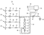
図2は、第1〜4の風車25、26、27、28を有する本発明に係るウインドファーム24の例示的実施形態の概略図を示す。風車25、26、27、28の風車発電機29、30、31、32はそれぞれ定格2.3MWの電力を生成する。風車トランスは電力を690Vから33kVに変換する。インピーダンス41、42、43、44を有するケーブル37、38、39、40を介して、電力は共通結合点45に導かれる。共通結合点45から、電力はウインドファームトランス47の中間電圧側に導かれ、電力は通常33kVから132kVに変圧される。しかし、変圧率は可変であっても良い。この場合、インドファームの適応を異なる外部送電系統48に広げることができる。さらに、可変の変圧率を有するウインドファームトランスによって、外部送電系統における障害発生時の外部送電系統のサポートが向上される。電力はウインドファームトランス47の高電圧側から無効電力補償器49を介して外部送電系統48に導かれる。この例示的実施形態における無効電力補償器49は、リアクタンスの抵抗に対する比が10である。エネルギー貯蔵装置46は共通結合点45に接続されている。しかし、代替的な実施形態では、エネルギー貯蔵装置46はウインドファームトランス47の高電圧側にも同様に接続されていてよい。エネルギー貯蔵装置46は、電池50、制御回路51、変換器52、フィルタユニット53およびインジェクショントランス54を有する。制御回路51は直流電流でもって電池50の充放電を制御する。変換器52は、直流電流を、共通結合点45において供給される交流電流に変換する。変換器52の出力はフィルタユニット53に接続され、フィルタユニットは、インジェクショントランス54に電流が供給される前に電流を平滑化する。インジェクショントランス54はたとえば有利には3相トランスである。インジェクショントランス54は共通結合点45において交流電流を供給するために用いられるだけでなく、共通結合点45における電圧をフィルタ52側におけるより低い値に変換するためにも用いられる。これによって、エネルギー貯蔵要素46のための低電圧装置を用いることができる。ウインドファームコントローラ55は、ウインドファームトランス47の前および/または後における電圧、周波数、有効電力および無効電力を測定する。これらのパラメタに基づいて、ウインドファームコントローラ55は、風車25、26、27、28およびエネルギー貯蔵要素46、有利には制御回路51を、制御信号56、57、58、59により制御する。制御回路51は、ウインドファームコントローラ55が周波数制御から回避されるように、ウインドファームコントローラ55と双方向的に通信する。ウインドファームコントローラ55はたとえば制御信号58によりエネルギー貯蔵要素46から取り出すべき電力量を決定し、同時に、電池50の残存エネルギーレベルに関する制御回路51からのフィードバックを受信する。
FIG. 2 shows a schematic view of an exemplary embodiment of a
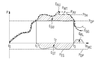
図3は本発明に係るウインドファームの作動方法の例示的実施形態を示す。図には、現在吹いている風から利用可能な電力PAV、風車が実際に生産する有効電力PWT、ウインドファームが外部送電系統に供給する有効電力PGG、および、エネルギー貯蔵要素が貯蔵する、放出する有効電力PESの時間経過が示されている。 FIG. 3 shows an exemplary embodiment of a method for operating a wind farm according to the present invention. The figure shows the power P AV that can be used from the wind that is currently blowing, the effective power P WT that the windmill actually produces, the effective power P GG that the wind farm supplies to the external power transmission system, and the energy storage element the time course of the active power P ES to release is shown.
t0で風が吹き始めると、風車は基本的に利用可能な電力PAVの全てを用いて有効電力PWTを生産してよい。エネルギーはエネルギー貯蔵要素には未だ貯蔵されていない。したがって、ウインドファームが外部送電系統に供給する有効電力PGGはPWTおよびPAVに等しい。利用可能な電力PAVがt1において消費者が要求する有効電力PDPを上回るとき、風車は、有効電力PWTを生成するために、全ての利用可能な有効電力PAVを依然として使い続ける。外部送電系統に供給される有効電力PGGは、エネルギー貯蔵要素を充電するために用いられる有効電力PESの分だけ減少する。このようにして、余分なエネルギーESUが貯蔵エネルギーESTとしてエネルギー貯蔵要素に貯蔵される。エネルギー貯蔵要素の充電電力は、たとえば、所定の閾値PTHに制限される。t2において、利用可能電力PAVが要求有効電力を、PTHを超える量上回る場合、たとえば、風車により生産される有効電力PWTはエネルギー貯蔵要素の損傷を避けるために低減される。風が弱まり、利用可能電力PAVが要求電力PDPを下回る場合、エネルギーERLがエネルギー貯蔵要素から放出され、その結果、より多くの有効電力PGGが外部送電系統に供給可能である。このようにして、低風速状態においても消費者の要求はより良く満たされうる。 As the wind starts to blow at t 0, the wind turbine may produce active power P WT using all basically available power P AV. Energy is not yet stored in the energy storage element. Accordingly, active power P GG which wind farms are supplied to the external grid is equal to P WT and P AV. When the available power P AV exceeds the active power P DP requested by the consumer at t 1 , the windmill will continue to use all available active power P AV to generate the active power P WT . The effective power PGG supplied to the external power transmission system is reduced by the amount of the effective power PES used to charge the energy storage element. Thus, excess energy E SU is stored in the energy storage element as stored energy E ST. The charging power of the energy storage element is limited to a predetermined threshold value PTH , for example. In t 2, available power P AV is the required active power, if the above amount exceeds P TH, for example, active power P WT produced by the wind turbine is reduced in order to avoid damaging the energy storage element. When the wind weakens and the available power P AV falls below the required power P DP , energy E RL is released from the energy storage element, so that more active power P GG can be supplied to the external transmission system. In this way, consumer demands can be better met even in low wind speed conditions.
図4は、本発明に係る例示的なウインドファームのための例示的な制御手段を示す。比較器60はウインドファームにより提供される電力PWFを、風車とウインドファームのエネルギー貯蔵要素との共通結合点において利用可能な電力PPPCと比較する。その差はウインドファームコントローラ61に送られ、ウインドファームコントローラは風車により供給されるべき新たな好ましい電力PTOを決定する。除算器62はこの好ましい電力PTOを関係する風車の数で割り、個々の設定値PISPがこれらの風車に送られる。
FIG. 4 shows an exemplary control means for an exemplary wind farm according to the present invention. The
要素63は、ウインドファームにより提供される電力PWF、および、現在の風の状況により利用可能な利用可能電力PAVを監視する。PAVがPWFを上回る場合、要素63はPAVの値を比較器64に送り、比較器においてPTOからPAVが減ぜられる。得られる差PEBは負であり、すなわち、制御回路65は電池を正の電力PBで充電し始める。制御回路には、電池を充電および/または放電するための、かつ、上限電力リミッタPULおよび下限電力リミッタPLLを設定するための入力が供給される。
図5は、図4を参照して説明されたような実施のために用いることができる、制御回路65の例示的実施形態を示す。PEBがたとえば制御回路によって供給され、制御回路はたとえばアンチワインドアップ(anti-windup)を有するPIコントローラである。制御回路はたとえば、増幅回路71、69、除算器66、比較器67、積分器68および加算器72、70を有する。さらに、レートリミッタ73および飽和瞬時制御回路74が含まれても良い。飽和瞬時制御回路74は、上限電力リミッタPULおよび下限電力リミッタPLLに関する入力により影響されうる。制御回路65は最終的に電池に関する充電電力PBを決定する。上限電力PULおよび下限電力PLLは事象依存的、たとえば、伝送システムオペレータからの電力需要、市価、周波数に関する事象などに依存していても良い。これらの限度の最高値は最大の充電電力閾値であってよく、この閾値はたとえば電池が充電/放電の間にどれだけの量のパワーフローに耐えうるかを示す。
FIG. 5 shows an exemplary embodiment of a
図6は、電池の過充電を避けるための手段を示す。充電電力PBは監視され、貯蔵されたエネルギーの量を知るために積分器75で積分される。積分器は監視し、さらに、信号SDを受信する。この信号はエネルギー貯蔵装置からの電力が外部送電系統に供給されるときに電池が放電するときの信号である。貯蔵されたエネルギー量が最大エネルギーレベル76を上回るとき、電池は貯蔵し、比較器77は、充電が止められるべきであるという信号SSCを発する。
FIG. 6 shows a means for avoiding overcharging of the battery. The charging power P B is monitored and integrated with an
図7は、本発明に係るウインドファーム78の例示的実施形態の概略図を示す。図2に示す実施形態と異なり、風車79、80、81はそれぞれ風車発電機82、83、84、風車トランス85、86、87を有し、インピーダンス92、93、94を有するケーブル89、90、91を介して共通結合点88に接続されている。エネルギー貯蔵要素95もまた共通結合点88に接続されている。共通結合点の後で、ウインドファームトランス96が電圧を外部送電系統97の電圧に適合させるために設けられている。ウインドファーム78は無効電力補償器98を介して外部送電系統97に接続されている。エネルギー貯蔵要素95は電池99、瞬時電圧制御回路100、交流電流と直流電流との変換のための変換器101、フィルタ102、バイパススイッチ107、インジェクショントランス106を有する。フィルタ102のインダクタンス(inductivity)およびキャパシタンス(capacity)は、変換器101により提供される交流電流により平滑化される。これは変換器101により生成される不要な高次高調波成分を除くことにより行うことができる。バイパススイッチ107によりエネルギー貯蔵要素95は共通結合点88から切り離すことができる。バイパススイッチは、送電系統の障害発生時にエネルギー貯蔵要素95を保護することができる。キャパシタンス105により、電池99には交流電流が印加されない。ウインドファームコントローラ108はたとえば信号111により瞬時電圧制御回路100を制御する。ウインドファームコントローラ108は、たとえば、ウインドファームトランス96の前および/または後の電圧、周波数、有効電力および/または無効電力を測定する。これらのパラメタに基づいて、ウインドファームコントローラ108はたとえば、制御信号109、110、111により、風車79、80、81およびエネルギー貯蔵要素95、具体的には瞬時電圧制御回路100を制御する。瞬時電圧制御回路100は変換器101および電池99に対して働き、これにより、エネルギー貯蔵要素95は共通結合点88において電力をインジェクションし、これは予め定めた周波数および電圧ならびに予め定めた有効成分および無効成分を有するものである。瞬時電圧低下補償回路100の最大補償能力は、たとえば、電池により供給される有効電力量に依存する。変換器101はたとえばパルス幅変調電圧型インバータである。パルス幅変調電圧型インバータはたとえば風車に用いられたものと同じである。インジェクショントランス106の高電圧側は共通結合点88とウインドファームトランス96とを接続する配電ラインに直列に接続されており、一方で、インジェクショントランス106の低電圧側はエネルギー貯蔵装置95の残りの装置に接続されている。たとえば、3相用の瞬時電圧制御回路100の場合は、3つの単相電圧インジェクショントランス106または1つの3相電圧インジェクショントランス106が配電ラインに接続されている。1つの単相電圧インジェクショントランス106には単相用の瞬時電圧制御回路100で十分である。3相電圧インジェクショントランス106について、デルタ/オープンまたはスター/オープン構成のいずれかの3相電圧インジェクショントランス106を用いることができる。インジェクショントランス106は、たとえば、変換器101のフィルタされた出力により供給された電圧を所望のレベルに増大させ、同時にエネルギー貯蔵装置95をウインドファーム78の他の部分から絶縁する。
FIG. 7 shows a schematic diagram of an exemplary embodiment of a
ウインドファームコントローラは、たとえば、電圧低下を検出し、エネルギー貯蔵要素95に制御信号111を送る。典型的な電圧変化が図8に示されている。図8の上側の図のプロットは、外部送電系統、たとえば図7に示す外部送電系統の電圧を示す。洋上ウインドパークの場合、電圧114はたとえば陸側の接続点において測定される。電圧が低下する場合、瞬時電圧制御回路100はたとえばウインドファームコントローラ108から信号111を受信し、その結果、エネルギー貯蔵装置95は、図8の中程の図のプロットに示されるような必要な電圧113を確立する。図8の下側の図のプロットに示される共通結合点88における電圧は、したがって、これらの電圧の合計である。図9は、これらの電位を可視化したものを示す。
For example, the wind farm controller detects a voltage drop and sends a
図10は、2相の電圧が定格電圧よりも高い場合の例示的な電圧変化を示す(上側の図参照)。瞬時電圧低下補償回路100により、たとえばこれらの2相の電圧は中程の図に示される量の分だけ減ぜられ、最終的に全ての3相が下側の図に示されるように定格電圧を有する。
FIG. 10 shows an exemplary voltage change when the two-phase voltage is higher than the rated voltage (see upper diagram). By means of the instantaneous voltage
本発明のいくつかの実施形態では、たとえば、1つのエネルギー貯蔵装置が共通結合点に接続されている。しかし、他の実施形態では、複数のエネルギー貯蔵要素が設けられていても良い。これらのエネルギー貯蔵要素は、さらに個々の風車に設けられていても良い。 In some embodiments of the invention, for example, one energy storage device is connected to the common coupling point. However, in other embodiments, a plurality of energy storage elements may be provided. These energy storage elements may also be provided in individual wind turbines.
図11は、2つのエネルギー貯蔵要素138、137を有するウインドファーム115の例示的実施形態を示す。エネルギー貯蔵要素は、4つの風車116、117、118、119のうちの2つの風車118、119に設けられている。各ウインドファームは発電機120、121、122、123およびウインドファームトランス124、125、126、127を有し、インピーダンス133、134、135、136を有するケーブル128、129、130、131を介して共通結合点132に接続されている。エネルギー貯蔵要素138、137は、それぞれ電池142、制御回路143、変換器144、フィルタ145およびインジェクショントランス146を有する。制御回路143はウインドファームコントローラ151からの信号150、149により制御され、これはさらに風車116、117、118、119をウインドファームトランス139の前および/または後で測定された値に基づいて制御信号147、148により制御する。ウインドファーム115は無効電力補償器141を介して外部送電系統140に接続されている。
FIG. 11 shows an exemplary embodiment of a
「含む」、「有する」の語は他の要素またはステップを除くものではなく、「1つ」と記載されていない限り複数を除くものでない。また、異なる実施形態に関連して記載された要素が組み合わされても良い。請求項における参照番号は請求項に記載の発明の範囲を限定するものと理解されるべきではない。 The word “comprising” does not exclude other elements or steps and does not exclude a plurality unless it is stated as “one”. In addition, elements described in relation to different embodiments may be combined. Any reference signs in the claims should not be construed as limiting the scope of the claimed invention.
1 ウインドファーム、 2、3、4 風車、 8、9、10風車トランス、 21 ウインドファームコントローラ 1 wind farm, 2, 3, 4 windmill, 8, 9, 10 windmill transformer, 21 wind farm controller
Claims (15)
該ウインドファームは、風車と、エネルギー貯蔵装置とを有しており、
該ウインドファームは外部送電系統に接続されており、
該方法は、
要求有効電力を決定するステップと、
要求無効電力を決定するステップと、
前記風車の生産電力を決定するステップと、
生産電力が要求有効電力、要求無効電力、または、要求有効電力と要求無効電力とのベクトル和を上回るときに、前記エネルギー貯蔵装置を充電するステップと、
を含む、
ことを特徴とする方法。 Wind farm operating method,
The wind farm has a windmill and an energy storage device,
The wind farm is connected to an external power transmission system,
The method
Determining the required active power; and
Determining the required reactive power;
Determining the production power of the windmill;
Charging the energy storage device when the produced power exceeds required active power, required reactive power, or a vector sum of required active power and required reactive power;
including,
A method characterized by that.
前記求められた外部送電系統の電圧が予め定めた外部送電系統の電圧と異なるときに、前記エネルギー貯蔵装置により補償電圧を供給するステップと、
をさらに含む、請求項1から5のいずれか1項記載のウインドファームの作動方法。 Obtaining a voltage of the external power transmission system;
Supplying the compensation voltage by the energy storage device when the determined voltage of the external power transmission system is different from the voltage of the predetermined external power transmission system;
The method for operating a wind farm according to any one of claims 1 to 5, further comprising:
Applications Claiming Priority (2)
| Application Number | Priority Date | Filing Date | Title |
|---|---|---|---|
| EP11182016.3A EP2573895B1 (en) | 2011-09-20 | 2011-09-20 | Method for operating a wind farm, wind farm controller and wind farm |
| EP11182016.3 | 2011-09-20 |
Publications (2)
| Publication Number | Publication Date |
|---|---|
| JP2013070603A true JP2013070603A (en) | 2013-04-18 |
| JP2013070603A5 JP2013070603A5 (en) | 2015-09-17 |
Family
ID=44862465
Family Applications (1)
| Application Number | Title | Priority Date | Filing Date |
|---|---|---|---|
| JP2012206878A Pending JP2013070603A (en) | 2011-09-20 | 2012-09-20 | Method for operating wind farm, wind farm controller and wind farm |
Country Status (10)
| Country | Link |
|---|---|
| US (1) | US9166509B2 (en) |
| EP (1) | EP2573895B1 (en) |
| JP (1) | JP2013070603A (en) |
| KR (1) | KR20130031227A (en) |
| CN (1) | CN103023061A (en) |
| AU (1) | AU2012213941B2 (en) |
| BR (1) | BR102012023694A2 (en) |
| CA (1) | CA2790222A1 (en) |
| DK (1) | DK2573895T3 (en) |
| ES (1) | ES2448794T3 (en) |
Cited By (3)
| Publication number | Priority date | Publication date | Assignee | Title |
|---|---|---|---|---|
| JP2016535583A (en) * | 2013-11-05 | 2016-11-10 | オープンハイドロ アイピー リミテッド | Method for protecting device and power generation system |
| JP2016538819A (en) * | 2013-11-05 | 2016-12-08 | オープンハイドロ アイピー リミテッド | Power generation system, power control method, and device protection method |
| CN110890766A (en) * | 2019-11-28 | 2020-03-17 | 山东理工大学 | Power distribution network mobile energy storage configuration method based on Fourier-Legendre series |
Families Citing this family (23)
| Publication number | Priority date | Publication date | Assignee | Title |
|---|---|---|---|---|
| PT2394329E (en) | 2009-02-09 | 2016-01-19 | Younicos Inc | Discharging batteries |
| US8471520B2 (en) | 2010-05-04 | 2013-06-25 | Xtreme Power Inc. | Managing renewable power generation |
| US9604761B2 (en) | 2012-09-28 | 2017-03-28 | S. C. Johnson & Son, Inc. | Storage bag with features that facilitate sealing and unsealing of the bag |
| US9685887B2 (en) | 2012-10-12 | 2017-06-20 | Younicos Inc. | Controlling power conversion systems |
| US9368968B2 (en) | 2012-12-28 | 2016-06-14 | Younicos, Inc. | Responding to local grid events and distributed grid events |
| US9276425B2 (en) | 2012-12-28 | 2016-03-01 | Younicos Inc. | Power management systems with dynamic target state of charge |
| US9859828B2 (en) | 2013-02-07 | 2018-01-02 | Vestas Wind Systems A/S | Power plant and energy storage system for provision of grid ancillary services |
| DE102013206241A1 (en) * | 2013-04-09 | 2014-10-09 | Senvion Se | Wind turbine with extended voltage range |
| CN105308312B (en) | 2013-06-03 | 2020-03-17 | 维斯塔斯风力系统集团公司 | Wind power plant controller |
| KR101480533B1 (en) * | 2013-06-28 | 2015-01-08 | 한국전력공사 | Apparatus and method for interconnecting distributed generations into power grid |
| DE102013222452A1 (en) * | 2013-11-05 | 2015-05-07 | Wobben Properties Gmbh | Method for operating a wind energy plant |
| KR101475486B1 (en) * | 2013-11-22 | 2014-12-22 | 삼성중공업 주식회사 | Control system for wind farm |
| EP3075055B1 (en) * | 2013-11-28 | 2019-03-06 | Vestas Wind Systems A/S | A power plant controller for generating a power reference to wind turbine generators |
| US10205317B2 (en) * | 2014-08-08 | 2019-02-12 | Nec Corporation | Management of grid-scale energy storage systems for multiple services |
| US10054108B2 (en) * | 2014-10-10 | 2018-08-21 | General Electric Company | Wind turbine system and method for controlling a wind turbine system by power monitoring |
| EP3012938A1 (en) * | 2014-10-24 | 2016-04-27 | Siemens Aktiengesellschaft | Method to stabilize an electrical grid |
| WO2017034051A1 (en) * | 2015-08-26 | 2017-03-02 | 전자부품연구원 | System and method for controlling wind farm composed of various wind turbines |
| CN105375502B (en) * | 2015-11-19 | 2018-06-19 | 珠海格力电器股份有限公司 | A kind of real-time control method and system of photovoltaic electricity |
| DE102016105662A1 (en) | 2016-03-29 | 2017-10-05 | Wobben Properties Gmbh | Method for feeding electrical power into an electrical supply network with a wind farm and wind farm |
| DE102016106215A1 (en) | 2016-04-05 | 2017-10-05 | Wobben Properties Gmbh | Method and wind turbine for feeding electrical power |
| KR102173835B1 (en) * | 2018-10-11 | 2020-11-05 | 한국전력공사 | Apparatus for controlling transformer utility for new renewable energy and method thereof |
| CN113653593A (en) * | 2021-09-06 | 2021-11-16 | 中国华能集团清洁能源技术研究院有限公司 | Control method, system and device of offshore floating type double-wind-wheel wind generating set |
| CN114221354A (en) * | 2021-12-27 | 2022-03-22 | 上海电气风电集团股份有限公司 | Power control method and system for wind power plant and readable storage medium |
Citations (7)
| Publication number | Priority date | Publication date | Assignee | Title |
|---|---|---|---|---|
| JP2000041338A (en) * | 1998-05-18 | 2000-02-08 | Nissin Electric Co Ltd | System interlinkage device |
| JP2000175360A (en) * | 1998-12-02 | 2000-06-23 | Nissin Electric Co Ltd | Inverse power flow method of power storing system |
| JP2002285949A (en) * | 2001-03-26 | 2002-10-03 | Ryuichi Shimada | Wind power generation plant using power storing device with improved efficiency |
| JP2004282871A (en) * | 2003-03-14 | 2004-10-07 | Ishikawajima Harima Heavy Ind Co Ltd | Output stabilizer and control method therefor for distributed power source |
| US20090167088A1 (en) * | 2004-06-30 | 2009-07-02 | Llorente Gonzalez Jose Igna Cio | Method and device for preventing the disconnection of an electric power generating plant from the electrical grid |
| WO2010058459A1 (en) * | 2008-11-19 | 2010-05-27 | 東芝三菱電機産業システム株式会社 | Output power control apparatus |
| WO2010073310A1 (en) * | 2008-12-22 | 2010-07-01 | 日本風力開発株式会社 | Power management control system for natural energy power generation system provided with storage battery |
Family Cites Families (8)
| Publication number | Priority date | Publication date | Assignee | Title |
|---|---|---|---|---|
| US6858953B2 (en) * | 2002-12-20 | 2005-02-22 | Hawaiian Electric Company, Inc. | Power control interface between a wind farm and a power transmission system |
| ES2277724B1 (en) * | 2005-02-23 | 2008-06-16 | GAMESA INNOVATION & TECHNOLOGY, S.L. | PROCEDURE AND DEVICE FOR INJECTING REACTIVE INTENSITY DURING A NETWORK VOLTAGE HOLE. |
| CN101114771B (en) * | 2007-09-03 | 2010-11-10 | 清华大学 | Wind-electricity integration power stabilizer based on active type voltage source DC power transmission |
| US20100138063A1 (en) * | 2009-08-28 | 2010-06-03 | General Electric Company | Systems and methods for interfacing renewable power sources to a power grid |
| US7908036B2 (en) | 2009-10-20 | 2011-03-15 | General Electric Company | Power production control system and method |
| CN101917014B (en) * | 2010-08-20 | 2012-06-13 | 河海大学 | Accumulator charging and discharging control method for smoothening power fluctuation of wind power station |
| CN101931241B (en) * | 2010-09-21 | 2013-04-17 | 许继集团有限公司 | Wind farm grid-connected coordination control method |
| WO2012070141A1 (en) * | 2010-11-25 | 2012-05-31 | 三菱重工業株式会社 | Output control method and output control device for wind-powered electricity generating facility |
-
2011
- 2011-09-20 ES ES11182016.3T patent/ES2448794T3/en active Active
- 2011-09-20 DK DK11182016.3T patent/DK2573895T3/en active
- 2011-09-20 EP EP11182016.3A patent/EP2573895B1/en not_active Revoked
-
2012
- 2012-08-14 AU AU2012213941A patent/AU2012213941B2/en not_active Expired - Fee Related
- 2012-09-13 US US13/613,513 patent/US9166509B2/en active Active
- 2012-09-18 CA CA2790222A patent/CA2790222A1/en not_active Abandoned
- 2012-09-19 BR BRBR102012023694-0A patent/BR102012023694A2/en not_active IP Right Cessation
- 2012-09-20 JP JP2012206878A patent/JP2013070603A/en active Pending
- 2012-09-20 KR KR1020120104528A patent/KR20130031227A/en not_active Application Discontinuation
- 2012-09-20 CN CN2012103511673A patent/CN103023061A/en active Pending
Patent Citations (7)
| Publication number | Priority date | Publication date | Assignee | Title |
|---|---|---|---|---|
| JP2000041338A (en) * | 1998-05-18 | 2000-02-08 | Nissin Electric Co Ltd | System interlinkage device |
| JP2000175360A (en) * | 1998-12-02 | 2000-06-23 | Nissin Electric Co Ltd | Inverse power flow method of power storing system |
| JP2002285949A (en) * | 2001-03-26 | 2002-10-03 | Ryuichi Shimada | Wind power generation plant using power storing device with improved efficiency |
| JP2004282871A (en) * | 2003-03-14 | 2004-10-07 | Ishikawajima Harima Heavy Ind Co Ltd | Output stabilizer and control method therefor for distributed power source |
| US20090167088A1 (en) * | 2004-06-30 | 2009-07-02 | Llorente Gonzalez Jose Igna Cio | Method and device for preventing the disconnection of an electric power generating plant from the electrical grid |
| WO2010058459A1 (en) * | 2008-11-19 | 2010-05-27 | 東芝三菱電機産業システム株式会社 | Output power control apparatus |
| WO2010073310A1 (en) * | 2008-12-22 | 2010-07-01 | 日本風力開発株式会社 | Power management control system for natural energy power generation system provided with storage battery |
Cited By (3)
| Publication number | Priority date | Publication date | Assignee | Title |
|---|---|---|---|---|
| JP2016535583A (en) * | 2013-11-05 | 2016-11-10 | オープンハイドロ アイピー リミテッド | Method for protecting device and power generation system |
| JP2016538819A (en) * | 2013-11-05 | 2016-12-08 | オープンハイドロ アイピー リミテッド | Power generation system, power control method, and device protection method |
| CN110890766A (en) * | 2019-11-28 | 2020-03-17 | 山东理工大学 | Power distribution network mobile energy storage configuration method based on Fourier-Legendre series |
Also Published As
| Publication number | Publication date |
|---|---|
| EP2573895A1 (en) | 2013-03-27 |
| AU2012213941A1 (en) | 2013-04-04 |
| DK2573895T3 (en) | 2014-03-10 |
| ES2448794T3 (en) | 2014-03-17 |
| EP2573895B1 (en) | 2014-01-15 |
| AU2012213941B2 (en) | 2016-09-15 |
| BR102012023694A2 (en) | 2014-12-23 |
| US20130249215A1 (en) | 2013-09-26 |
| KR20130031227A (en) | 2013-03-28 |
| US9166509B2 (en) | 2015-10-20 |
| CA2790222A1 (en) | 2013-03-20 |
| CN103023061A (en) | 2013-04-03 |
Similar Documents
| Publication | Publication Date | Title |
|---|---|---|
| JP2013070603A (en) | Method for operating wind farm, wind farm controller and wind farm | |
| CN105659461B (en) | Method for controlling wind power plant and wind power plant | |
| DK2688172T3 (en) | Method and arrangement for adaptive control of wind turbines in a wind farm | |
| EP3080887B1 (en) | A wind power plant, and a method for increasing the reactive power capability of a wind power plant | |
| Ko et al. | Active use of DFIG-based variable-speed wind-turbine for voltage regulation at a remote location | |
| JP2013102684A (en) | Method for operating wind park | |
| US9551323B2 (en) | Power plant control during a low voltage or a high voltage event | |
| CA2911333A1 (en) | Method for feeding electrical power into an electrical supply network | |
| Wei et al. | MPC-based DC-link voltage control for enhanced high-voltage ride-through of offshore DFIG wind turbine | |
| JP2020522977A (en) | How to drive a wind farm | |
| US10958071B2 (en) | Adaptive active power control in renewable energy power plants | |
| US20150249338A1 (en) | Method and controller for continuously operating a plurality of electric energy generating machines during a high voltage condition | |
| Lin et al. | Coordinated frequency control strategy for VSC-HVDC-connected wind farm and battery energy storage system | |
| Shukla et al. | Low voltage ride through (LVRT) ability of DFIG based wind energy conversion system II | |
| Youssef et al. | Wind energy facts applications and stabilization schemes | |
| RU2649868C2 (en) | Method for controlling wind power plants | |
| CN110544955B (en) | Operation control method and system of wind turbine generator in power grid voltage out-of-limit interval | |
| Gupta et al. | Comparative study of SDBR and R-type SSFCL for enhancement of low voltage ride-through capability of wind-farms | |
| US20220364544A1 (en) | Method for operating a wind turbine, and a power plant | |
| US11879433B2 (en) | Method for operating a wind turbine, and a power plant | |
| CN106451558A (en) | Power network system with large-scale wind power integration | |
| Zhang | Investigations of grid-connected wind power system: low voltage ride through and power quality issues | |
| CN113424389A (en) | Boosting reactive current injection from wind turbine generators | |
| Itani | Short-term frequency support utilizing inertial response of variable-speed wind plants | |
| Taylor | Voltage impact studies investigating reactive power control modes of inverter-coupled wind generation connected to a weak rural feeder |
Legal Events
| Date | Code | Title | Description |
|---|---|---|---|
| A521 | Request for written amendment filed |
Free format text: JAPANESE INTERMEDIATE CODE: A523 Effective date: 20150731 |
|
| A621 | Written request for application examination |
Free format text: JAPANESE INTERMEDIATE CODE: A621 Effective date: 20150731 |
|
| A977 | Report on retrieval |
Free format text: JAPANESE INTERMEDIATE CODE: A971007 Effective date: 20160711 |
|
| A131 | Notification of reasons for refusal |
Free format text: JAPANESE INTERMEDIATE CODE: A131 Effective date: 20160719 |
|
| A601 | Written request for extension of time |
Free format text: JAPANESE INTERMEDIATE CODE: A601 Effective date: 20161013 |
|
| A02 | Decision of refusal |
Free format text: JAPANESE INTERMEDIATE CODE: A02 Effective date: 20170313 |