JP2013067352A - Speed change control device of vehicle - Google Patents
Speed change control device of vehicle Download PDFInfo
- Publication number
- JP2013067352A JP2013067352A JP2011209277A JP2011209277A JP2013067352A JP 2013067352 A JP2013067352 A JP 2013067352A JP 2011209277 A JP2011209277 A JP 2011209277A JP 2011209277 A JP2011209277 A JP 2011209277A JP 2013067352 A JP2013067352 A JP 2013067352A
- Authority
- JP
- Japan
- Prior art keywords
- torque
- control
- motor
- zone
- time
- Prior art date
- Legal status (The legal status is an assumption and is not a legal conclusion. Google has not performed a legal analysis and makes no representation as to the accuracy of the status listed.)
- Withdrawn
Links
- 230000008859 change Effects 0.000 title claims abstract description 122
- 230000005540 biological transmission Effects 0.000 claims abstract description 68
- 230000004044 response Effects 0.000 description 21
- 230000000875 corresponding effect Effects 0.000 description 13
- 230000007423 decrease Effects 0.000 description 12
- 238000000034 method Methods 0.000 description 10
- 230000003247 decreasing effect Effects 0.000 description 7
- 230000000694 effects Effects 0.000 description 5
- 238000001125 extrusion Methods 0.000 description 5
- 230000006870 function Effects 0.000 description 5
- 238000012508 change request Methods 0.000 description 4
- 230000036962 time dependent Effects 0.000 description 4
- 230000009471 action Effects 0.000 description 3
- 230000001276 controlling effect Effects 0.000 description 3
- 230000007246 mechanism Effects 0.000 description 3
- 230000008569 process Effects 0.000 description 3
- 230000009467 reduction Effects 0.000 description 3
- 230000001133 acceleration Effects 0.000 description 2
- 230000000052 comparative effect Effects 0.000 description 2
- 239000000446 fuel Substances 0.000 description 2
- 230000004048 modification Effects 0.000 description 2
- 238000012986 modification Methods 0.000 description 2
- 230000007704 transition Effects 0.000 description 2
- 238000013459 approach Methods 0.000 description 1
- 238000004891 communication Methods 0.000 description 1
- 238000007796 conventional method Methods 0.000 description 1
- 230000002596 correlated effect Effects 0.000 description 1
- 238000010586 diagram Methods 0.000 description 1
- 238000002347 injection Methods 0.000 description 1
- 239000007924 injection Substances 0.000 description 1
- 230000001151 other effect Effects 0.000 description 1
- 230000001172 regenerating effect Effects 0.000 description 1
- 230000035939 shock Effects 0.000 description 1
- 230000002123 temporal effect Effects 0.000 description 1
- 230000009466 transformation Effects 0.000 description 1
Images


Classifications
-
- Y—GENERAL TAGGING OF NEW TECHNOLOGICAL DEVELOPMENTS; GENERAL TAGGING OF CROSS-SECTIONAL TECHNOLOGIES SPANNING OVER SEVERAL SECTIONS OF THE IPC; TECHNICAL SUBJECTS COVERED BY FORMER USPC CROSS-REFERENCE ART COLLECTIONS [XRACs] AND DIGESTS
- Y02—TECHNOLOGIES OR APPLICATIONS FOR MITIGATION OR ADAPTATION AGAINST CLIMATE CHANGE
- Y02T—CLIMATE CHANGE MITIGATION TECHNOLOGIES RELATED TO TRANSPORTATION
- Y02T10/00—Road transport of goods or passengers
- Y02T10/60—Other road transportation technologies with climate change mitigation effect
- Y02T10/62—Hybrid vehicles
Landscapes
- Control Of Transmission Device (AREA)
- Hybrid Electric Vehicles (AREA)
Abstract
Description
本発明は、変速時のトルク変動をモータトルクで補正する車両の変速制御装置に関する。 The present invention relates to a shift control device for a vehicle that corrects torque fluctuations during shift with motor torque.
従来、車両の駆動源としてエンジンとモータとを備えたハイブリッド車両では、車両の変速時にモータトルクで駆動トルクをアシストする制御を実施するものが知られている。すなわち、クラッチの断接に伴って変速機に入力されるエンジントルクが変動したときに、エンジントルクの変動量に見合ったモータトルクを変速機に与えることによって、駆動力の変動を抑制するものである。 Conventionally, a hybrid vehicle having an engine and a motor as a drive source of the vehicle is known that performs control for assisting the drive torque with the motor torque when the vehicle is shifted. In other words, when the engine torque input to the transmission fluctuates due to the clutch connection / disconnection, the motor torque corresponding to the engine torque fluctuation amount is given to the transmission to suppress the fluctuation of the driving force. is there.
例えば、クラッチの切断時には、変速機に入力されるエンジントルクが減少する。そのため、不足分のトルクをモータで補填すれば、変速機から駆動輪に伝達される駆動トルクが確保され、減速感を小さくすることができる。反対に、クラッチの係合時にはエンジンから入力されるエンジントルクが徐々に増加するため、これに合わせてモータトルクを徐々に減少させ、トルクの変動を相殺することによって、車両の押し出し感(加速感)を減少させることができる。 For example, when the clutch is disengaged, the engine torque input to the transmission decreases. Therefore, if the insufficient torque is compensated by the motor, the drive torque transmitted from the transmission to the drive wheels is secured, and the feeling of deceleration can be reduced. On the contrary, the engine torque input from the engine gradually increases when the clutch is engaged. Accordingly, the motor torque is gradually decreased in accordance with this, and the fluctuation of the torque is offset, thereby providing a feeling of pushing the vehicle (acceleration feeling). ) Can be reduced.
このように、モータのアシスト駆動力を制御することで変速時のトルクショックを低減する技術の一例としては、特許文献1に記載のものが挙げられる。一般に、モータによるアシスト制御では、適切なタイミングで適量のモータトルクが発生するようにモータを駆動することが求められる。
As described above, an example of a technique for reducing torque shock at the time of shifting by controlling the assist driving force of a motor is disclosed in
エンジンの出力が運転者の出力要求に見合った大きさである場合、変速時にクラッチで伝達されなくなったトルクに相当するモータトルクを発生させることで、変速中であっても出力要求に見合った駆動力を確保することが可能である。 When the engine output is large enough to meet the driver's output request, the motor torque corresponding to the torque that is no longer transmitted by the clutch at the time of shifting is generated, so that the drive can meet the output request even during shifting. It is possible to secure power.
しかしながら、変速時にクラッチで伝達されなくなったトルクを直接検出することはできないため、変速機に実際に入力されたエンジントルクを演算した上で、そのエンジントルクと要求トルクとの差を演算しなければならない。したがって、発生させるべきモータトルクが正確に把握されるのは、トルクが実際に不足した後となる。つまり、トルク不足に先行してモータトルクを正確に発生させることができず、さらにモータへのトルク指示からモータトルクが発生するまでには応答遅れが生じる。
このように、従来のアシスト制御では、モータの応答遅れによってクラッチ切断時にトルク抜け感が生じ、あるいはクラッチ接合時に押し出し感が発生するおそれがあり、ドライブフィーリングを向上させることが難しいという課題がある。
However, since it is impossible to directly detect the torque that is no longer transmitted by the clutch at the time of shifting, it is necessary to calculate the difference between the engine torque and the required torque after calculating the engine torque actually input to the transmission. Don't be. Therefore, the motor torque to be generated is accurately grasped after the torque is actually insufficient. That is, the motor torque cannot be accurately generated prior to the torque shortage, and a response delay occurs until the motor torque is generated from the torque instruction to the motor.
Thus, in the conventional assist control, there is a problem that it is difficult to improve drive feeling because there is a possibility that a feeling of torque loss may occur when the clutch is disengaged due to a response delay of the motor, or a feeling of extrusion may occur when the clutch is engaged. .
本件の目的の一つは、上記のような課題に鑑み創案されたもので、車両の変速制御装置に関し、変速動作に伴う駆動力の変動を効率的に抑制することである。
なお、この目的に限らず、後述する発明を実施するための形態に示す各構成により導かれる作用効果であって、従来の技術によっては得られない作用効果を奏することも本件の他の目的として位置づけることができる。
One of the objects of the present case has been devised in view of the above-described problems, and relates to a vehicle shift control device, and is to efficiently suppress fluctuations in driving force associated with a shift operation.
The present invention is not limited to this purpose, and is a function and effect derived from each configuration shown in the embodiments for carrying out the invention described later, and other effects of the present invention are to obtain a function and effect that cannot be obtained by conventional techniques. Can be positioned.
(1)ここで開示する車両の変速制御装置は、クラッチを介して変速機に接続されたエンジンと、前記クラッチの断接に伴うトルク変動を均すためのモータトルクを駆動輪に供給するモータと、を有する車両の変速制御装置である。
本変速制御装置は、前記車両に対する要求トルクと前記変速機に入力されるエンジントルクとのトルク差を演算する演算手段と、前記トルク差に応じた前記モータトルクを前記モータに出力させる制御手段とを備える。また、前記制御手段が、前記モータトルクの指示値の変化勾配を前記トルク差の変化勾配よりも大きく設定する第一制御と、前記第一制御の後に前記モータトルクの指示値の変化勾配を前記トルク差の変化勾配以下に設定する第二制御とを実施する。
(1) A vehicle shift control device disclosed herein includes an engine connected to a transmission via a clutch, and a motor that supplies drive torque to motor wheels for equalizing torque fluctuations associated with the engagement and disconnection of the clutch. And a shift control apparatus for a vehicle.
The shift control device includes a calculation unit that calculates a torque difference between a required torque for the vehicle and an engine torque input to the transmission, and a control unit that outputs the motor torque corresponding to the torque difference to the motor. Is provided. Further, the control means sets the change gradient of the instruction value of the motor torque to be larger than the change gradient of the torque difference, and sets the change gradient of the instruction value of the motor torque after the first control. The second control that is set below the change gradient of the torque difference is performed.
ここでいう変化勾配とは、単位時間あたりのトルク変化量の絶対値を意味する。言い換えれば、前記第一制御では、前記モータトルクの変化勾配が、その符号にかかわらず、前記トルク差の変化勾配よりも急勾配に設定される。また、前記第二制御では、前記モータトルクの変化勾配が、前記トルク差の変化勾配よりも緩勾配に設定される。 The change gradient here means the absolute value of the torque change amount per unit time. In other words, in the first control, the change gradient of the motor torque is set to be steeper than the change gradient of the torque difference regardless of the sign. In the second control, the change gradient of the motor torque is set to be gentler than the change gradient of the torque difference.
第一制御ではモータトルクの変化勾配がトルク差の変化勾配よりも大きく設定されるため、モータの応答遅れ時間が経過したときにエンジントルクに加算されるモータトルクの変化勾配が急勾配となり、変化分のエンジントルクが迅速に補償される。一方、その後の第二制御ではモータトルクの変化勾配がトルク差の変化勾配よりも小さく設定されるため、第一制御での過剰なアシストの影響を相殺するようにモータトルクが削減され、エンジントルクとモータトルクとの加算値(すなわち駆動トルク)が要求トルクに漸近する。 In the first control, since the change gradient of the motor torque is set larger than the change gradient of the torque difference, the change gradient of the motor torque added to the engine torque becomes steep when the response delay time of the motor elapses. Minute engine torque is quickly compensated. On the other hand, in the subsequent second control, since the change gradient of the motor torque is set smaller than the change gradient of the torque difference, the motor torque is reduced so as to offset the influence of excessive assist in the first control, and the engine torque And the sum of the motor torque (that is, the drive torque) gradually approaches the required torque.
(2)また、前記制御手段が、前記トルク差の変動開始時に前記第一制御を実施することが好ましい。
前記トルク差の変動開始時には、前記クラッチの開放に伴う変動開始時と、前記クラッチの係合に伴う変動開始時とが含まれる。また、前記トルク差の変動開始時は、前記モータトルクの立ち上がり時や立ち下がり時に相当する。
(2) Moreover, it is preferable that the said control means implements said 1st control at the time of the fluctuation | variation start of the said torque difference.
When the torque difference starts to change, a change start associated with the clutch opening and a change start accompanying the clutch engagement are included. The time when the torque difference starts to change corresponds to when the motor torque rises or falls.
(3)また、前記制御手段が、前記トルク差の変化勾配に対する前記モータトルクの指示値の変化勾配の比を補償率として演算し、前記第一制御時の前記補償率を1よりも大きく設定するとともに、前記第二制御時の前記補償率を1以下に設定することが好ましい。
(4)前記第一制御から前記第二制御への切り換え条件は種々考えられる。例えば、前記制御手段が、前記第一制御から前記第二制御への切り換え条件として、前記変速機に入力されるエンジントルクの値を参照することが好ましい。
(3) Further, the control means calculates a ratio of the change gradient of the indicated value of the motor torque to the change gradient of the torque difference as a compensation rate, and sets the compensation rate during the first control to be larger than 1. In addition, it is preferable to set the compensation rate during the second control to 1 or less.
(4) Various conditions for switching from the first control to the second control are conceivable. For example, it is preferable that the control means refers to a value of engine torque input to the transmission as a switching condition from the first control to the second control.
(5)上記の条件に加えて、あるいは代えて、前記制御手段が、前記第一制御から前記第二制御への切り換え条件として、前記モータトルクの値を参照することが好ましい。
(6)さらに上記の条件に加えて、あるいは代えて、前記制御手段が、前記第一制御から前記第二制御への切り換え条件として、前記トルク差の変動開始時からの経過時間を参照することが好ましい。
前記経過時間は、前記モータの応答遅れ時間に応じた期間とすることが好ましい。例えば、モータで発生した応答トルクが所定値になるまでにかかる時間とすることが考えられる。
(5) In addition to or instead of the above condition, the control means preferably refers to the value of the motor torque as a switching condition from the first control to the second control.
(6) Further, in addition to or instead of the above condition, the control means refers to the elapsed time from the start of the fluctuation of the torque difference as a switching condition from the first control to the second control. Is preferred.
The elapsed time is preferably a period according to the response delay time of the motor. For example, the time taken for the response torque generated by the motor to reach a predetermined value can be considered.
ここで開示する車両の変速制御装置によれば、モータトルクの変化勾配の緩急の順序に関して、トルク差の変化勾配を基準とし、モータトルクの変化勾配を大きく設定した後に小さく設定することで、モータで実際にトルクが発生するまでの応答遅れを抑制することができる。つまり、クラッチの断接に伴うトルク変動の幅を減少させることができる。
例えば、エンジントルクの立ち下がり時には、モータトルクのアシスト遅れによるトルク抜け感を低減させることができる。あるいは、エンジントルクの立ち上がり時には、モータトルクの残留による車両の押し出し感を低減させることができる。これにより、ドライブフィーリングを向上させることができる。
According to the shift control device for a vehicle disclosed herein, the motor torque change gradient is set based on the torque difference change gradient as a reference, and the motor torque change gradient is set large and then set to a small value. Thus, the response delay until the torque is actually generated can be suppressed. That is, it is possible to reduce the width of the torque fluctuation accompanying the clutch connection / disconnection.
For example, when the engine torque falls, it is possible to reduce a feeling of torque loss due to a delay in assisting the motor torque. Alternatively, when the engine torque rises, it is possible to reduce the feeling of pushing the vehicle due to residual motor torque. Thereby, drive feeling can be improved.
図面を参照して変速制御装置について説明する。なお、以下に示す実施形態はあくまでも例示に過ぎず、以下の実施形態で明示しない種々の変形や技術の適用を排除する意図はない。 The transmission control device will be described with reference to the drawings. Note that the embodiment described below is merely an example, and there is no intention to exclude various modifications and technical applications that are not explicitly described in the following embodiment.
[1.車両]
本実施形態の車両の変速制御装置は、図1に示す車両10に適用される。この車両10は、エンジン11及びモータ13を駆動源とするパラレル型のハイブリッド自動車である。エンジン11の出力軸には、クラッチ12a及びギヤボックス12bを内蔵した自動変速機12が接続される。
この自動変速機12は、動力伝達効率の高い手動変速機の機構を用いてクラッチ動作やギヤチェンジを自動化したAMT(Automated Manual Transmission)であり、エンジン11はクラッチ12aを介してギヤボックス12bに接続されている。
[1. vehicle]
The vehicle shift control device of the present embodiment is applied to the
This
クラッチ12aは、対向する摩擦係合要素間に生じる摩擦力の大きさを制御することによって動力伝達を断接する機構である。例えば、ギヤボックス12bでの変速時や車両10の停車時等には、クラッチ12aが開放状態(切断状態)に制御され、駆動輪14側への動力伝達が遮断される。また、車両10の走行時にはクラッチ12aが係合状態(直結状態)に制御され、エンジン11からの動力が駆動輪14側に伝達される。
The clutch 12a is a mechanism for connecting / disconnecting power transmission by controlling the magnitude of the frictional force generated between the opposing frictional engagement elements. For example, the clutch 12a is controlled to be in an open state (disconnected state) at the time of shifting in the
ギヤボックス12bは、動力が伝達される経路をなす歯車の組み合わせを可変とした、複数の歯車を内蔵する有段変速装置である。ギヤボックス12bに入力される回転数とギヤボックス12bから出力される回転数との比(変速比,減速比)は、ギヤボックス12b内での歯車の組み合わせに応じた値となる。エンジン11の出力は、ギヤボックス12bで設定された変速比に従って変速され、駆動輪14側に伝達される。
The
ギヤボックス12bには、電動式のモータ13が接続される。このモータ13は、電力の供給を受けてモータ駆動力を発生させるとともに、回転駆動力を受けて回生発電するモータジェネレータである。モータ13の取付位置はギヤボックス12bの出力軸の後位であり、クラッチ12aの断接状態に関わらずモータトルクTMを駆動輪14に伝達可能な構造とされている。なお、クラッチ12aの開放時にはモータトルクTMが駆動輪14に伝達される駆動トルクTWとなり、クラッチ12aの係合時にはギヤボックス12bに入力された入力エンジントルクTEとモータトルクTMとを合算したトルクが駆動トルクTWとなる。
An
モータ13は、例えばギヤボックス12bでの変速中のトルク不足を補償して、エンジン11の駆動力をアシストするように機能する。また、モータ13を駆動するための電力は、例えばインバータ15等の変電変圧装置を介して走行用のバッテリ16から供給される。
The
車両10の任意の位置には、アクセル操作量(アクセルペダルの踏み込み量)を検出するアクセルストロークセンサー7が設けられる。アクセル操作量は、運転者の加速要求や発進意思に対応するパラメーターであり、言い換えるとエンジン11の負荷(エンジン11に対する出力要求)に相関するパラメーターである。アクセルストロークセンサー7で検出されたアクセル操作量の情報は、後述するエンジン制御装置5に伝達される。
An
エンジン11のクランクシャフトには、その回転角を検出するエンジン回転数センサー8が設けられる。クランクシャフトの回転角の単位時間あたりの変化量(角速度)はエンジン11の実回転数Neに比例する。したがって、エンジン回転数センサー8は、エンジン11の実回転数Neを取得する機能を持つ。ここで取得された回転角や実回転数Neの情報は、エンジン制御装置5及び変速機制御装置6に伝達される。なお、エンジン回転数センサー8で検出された回転角の情報に基づき、エンジン制御装置5や変速機制御装置6の内部で実回転数Neを演算する構成としてもよい。
The crankshaft of the
また、自動変速機12にはクラッチ12aを介して自動変速機12の入力回転数Ntを検出する入力回転数センサー9が設けられる。この入力回転数センサー9は、例えばクラッチ12aとギヤボックス12bとの間の回転軸の回転数を入力回転数Ntとして検出する。ここで検出された入力回転数Ntの情報は、エンジン制御装置5及び後述する変速機制御装置6に伝達される。
Further, the
[2.制御装置]
車両10には、電子制御装置としてモータ制御装置1(モータECU),エンジン制御装置5(エンジンECU),変速機制御装置6(AMT ECU)が設けられる。これらの電子制御装置は、例えばマイクロプロセッサやROM,RAM等を集積したLSIデバイスや組み込み電子デバイスとして構成され、車両に設けられた車載ネットワーク網の通信ラインを介して互いに通信可能に接続される。
[2. Control device]
The
エンジン制御装置5は、エンジン11に関する点火系,燃料系,吸排気系及び動弁系といった広汎なシステムを制御する電子制御装置である。ここでは、エンジン11に要求されるトルクの大きさを基準としたトルクベース制御が実施される。
本実施形態のエンジン制御装置5は、運転者が車両10に要求するドライバ要求トルクTDを演算し、このドライバ要求トルクTDがエンジン11から出力されるように、エンジン11の各シリンダーに対して供給される空気量,燃料噴射量,点火タイミング,バルブリフト量,バルブタイミング等を制御する。ドライバ要求トルクTDの値は、アクセル操作量やエンジン11の実回転数Ne等に基づいて演算される。
The
The
また、エンジン制御装置5は、自動変速機12の変速時には、クラッチ12aの断接動作に先立ってエンジン11から出力されるトルクが若干減少するように、エンジン11の運転状態を制御する。
なお、ここでいうドライバ要求トルクTDには、運転者によって要求されるトルク以外のトルクを含めてもよい。例えば、運転者が車両10に要求するトルクと外部制御システム(オートクルーズ制御装置,補機用制御装置,車両安定制御装置等)によって要求されるトルクを加算したものを、ドライバ要求トルクTDとしてもよい。エンジン制御装置5で演算されたドライバ要求トルクTDの情報は、モータ制御装置1及び変速機制御装置6に伝達される。
Further, the
Here, the driver request torque T D referred may include a torque than the torque required by the driver. For example, the driver torque and external control systems that require the vehicle 10 (automatic cruise control device, auxiliary control device, a vehicle stability control apparatus, etc.) obtained by adding the torque required by the driver request torque T D Also good. Information of the calculated driver request torque T D in the
変速機制御装置6は、自動変速機12の変速動作を制御するものである。ここでは、エンジン11の運転状態や実回転数Ne,車両10の走行速度,自動変速機12の作動状態,シフトレバーの操作状態等に応じて変速操作の要否が判定され、クラッチ12aやギヤボックス12bの動作に関する各種演算処理が実施される。例えば、低速段での走行時に車両10の走行速度が増大すると、変速機制御装置6は変速操作を実施するか否かを判定し、必要に応じてシフトチェンジ要求信号を自動変速機12やエンジン制御装置5に伝達する。また、変速機制御装置6は、クラッチ12aの摩擦係合要素を駆動するための作動油圧や、ギヤボックス12b内の動力伝達機構を駆動するための作動油圧を演算し、これらに対応する制御信号を自動変速機12に伝達する。
The
また、本実施形態の変速機制御装置6は、エンジン11の実回転数Neをクラッチ12aの入力側回転数とみなし、入力回転数センサー9で検出された入力回転数Ntをクラッチ12aの出力側回転数とみなして、入力側回転数と出力側回転数との差回転数や回転数比を演算し、これらとドライバ要求トルクTDとに基づいて、ギヤボックス12bに入力された入力エンジントルクTEを演算する。ここで演算された入力エンジントルクTEの情報は、変速機制御装置6に伝達される。
Further, the
モータ制御装置1は、モータ13の動作を制御するものである。ここでは、車両10の走行状態やエンジン11の運転状態,バッテリ16の充電状態等に応じて、モータ13から出力されるトルク及び回転数が演算され、その動作が制御される。例えば、ギヤボックス12bでの変速時には、クラッチ12aの断接に伴うトルク変動を補償する大きさのモータトルクTMが演算されるとともに、そのモータトルクTMがモータ13から出力されるように、モータ13に印加される電圧や電流値に対応する制御信号が伝達される。
The
以下、モータ13で実際に発生するモータトルクTMに対して、モータ制御装置1内で演算される制御目標としてのトルクの値のことを「指示値S」と呼ぶ。一般に、自動変速機12の変速時にモータ制御装置1で指示値Sが演算されてから実際にモータトルクTMが発生するまでには、いわゆる応答遅れ(タイムラグ)が生じる。これに対して、本実施形態のモータ制御装置1は、このような変速時におけるモータ13の応答遅れを解消するための制御として、第一制御及び第二制御を実施する。
Hereinafter, the motor torque T M actually generated by the
第一制御とは、変速操作によってドライバ要求トルクTDと入力エンジントルクTEとが乖離したとき(すなわち、入力エンジントルクTEがドライバ要求トルクTDと比較して小さくなったとき)に、それらのトルク差Dの変化勾配GDよりもモータ13に出力するモータトルクTMの指示値Sの変化勾配GSを大きく設定する制御である。つまり、第一制御では、モータトルクTMを増加させる場合であっても減少させる場合であっても、モータトルクTMの変化速度が速くなるようにモータ13が制御される。
The first control, when the shift operation and the driver request torque T D and the input engine torque T E is deviation (i.e., when the input engine torque T E is reduced as compared to the driver request torque T D), a control for setting the change gradient G S indicated value S of the motor torque T M to be output to the
一方、第二制御とは、モータ13に出力するモータトルクTMの指示値Sの変化勾配GSをトルク差Dの変化勾配GD以下の範囲で設定する制御である。つまり、第二制御では、モータトルクTMの変化速度が緩やかに(遅く)なるようにモータ13が制御される。
これらの第一制御及び第二制御を実施するための手段として、モータ制御装置1にはトルク差演算部2,ゾーン判定部3及びモータ制御部4が設けられる。これらの手段は、電子回路(ハードウェア)によって実現してもよく、又はソフトウェアとしてプログラミングされたものとしてもよいし、あるいはこれらの機能のうちの一部をハードウェアとして設け、他部をソフトウェアとしたものであってもよい。
On the other hand, the second control is a control for setting the change gradient G S indicated value S of the motor torque T M to be output to the
As means for performing the first control and the second control, the
[2−1.トルク差演算部]
トルク差演算部2(演算手段)は、ドライバ要求トルクTDと入力エンジントルクTEとのトルク差Dとその変化勾配GDとを繰り返し演算するものである。ここでは、ドライバ要求トルクTDから入力エンジントルクTEを減じた値がトルク差Dとして演算される。トルク差Dの値は、クラッチ12aの締結力の低下に伴って伝達されなくなった不足分のトルクに相当する。また、トルク差Dの変化勾配GDは、単位時間(所定時間)あたりのトルク差Dの変化量である。
[2-1. Torque difference calculation unit]
Torque difference calculation section 2 (calculating means) is for repeatedly calculating a driver request torque T D with torque difference D between the input engine torque T E and the change gradient G D. Here, the value obtained by subtracting the input engine torque T E from the driver requested torque T D is calculated as the torque difference D. The value of the torque difference D corresponds to a shortage of torque that is not transmitted as the fastening force of the clutch 12a decreases. The change gradient G D of the torque difference D is the amount of change in torque difference D per unit time (predetermined time).
例えば、トルク差Dの演算周期をtとし、前回の演算周期で演算されたトルク差DをDn-1とし、今回の演算周期で演算されたトルク差DをDnとすると、変化勾配GDはGD=(Dn-Dn-1)/tで求められる。なお、ここでいう単位時間が演算周期tに等しいものと仮定すれば、上記の式中のtはt=1となることから、GD=Dn-Dn-1である。この場合、演算周期毎に得られるトルク差Dの変化量が変化勾配GDとなり、変化勾配GDの演算が簡略化される。ここで演算された変化勾配GDの値は、モータ制御部4に伝達される。
For example, if the calculation cycle of the torque difference D is t, the torque difference D calculated in the previous calculation cycle is D n-1, and the torque difference D calculated in the current calculation cycle is D n , the change gradient G D is obtained by G D = (D n −D n−1 ) / t. Assuming that the unit time here is equal to the calculation cycle t, t in the above equation is t = 1, and therefore G D = D n −D n−1 . In this case, the amount of change in torque difference D obtained in each operation cycle change gradient G D, and the calculation of the variation gradient G D is simplified. The value of the gradient change G D computed here, is transmitted to the
[2−2.ゾーン判定部]
ゾーン判定部3は、第一制御や第二制御といった複数の制御を変速期間内で使い分けるための複数のゾーン(期間)を設定し、これらの複数のゾーンを用いて変速動作の進捗状況を把握,判定するものである。ここでは、図3(a)に示すように、一つの変速期間が六つの制御ゾーンに分類される。ゾーン判定部3は、自動変速機12での変速時にその時点の変速動作が六つの制御ゾーンの何れに属しているかを随時判定し、判定結果をモータ制御部4に伝達する。
[2-2. Zone determination unit]
The
第一ゾーンは、変速期間の先頭に位置し、変速開始時に最初に設定されるゾーンである。変速開始時から所定時間幅の期間が第一ゾーンに相当する。第一ゾーンの始点は、変速機制御装置6からシフトチェンジ要求信号が自動変速機12に伝達された時点や、入力エンジントルクTEがドライバ要求トルクTDよりも小さくなった時点等とする。また、第一ゾーンの終点は、第一ゾーンの始点からの経過時間が予め設定された所定時間を超えた時点や、変速機制御装置6からモータ13に伝達されるモータトルクTMの指示値Sが所定値を超えた時点、モータ13で発生したモータトルクTMが所定値を超えた時点、入力エンジントルクTEが所定値以下となった時点等とする。
The first zone is located at the beginning of the shift period and is the first zone that is set when the shift is started. A period of a predetermined time width from the start of shifting corresponds to the first zone. Starting point of the first zone, and the time when the shift change request signal from the
第二ゾーンは第一ゾーンの直後に位置するゾーンであり、その始点は第一ゾーンの終点に一致する。また、第二ゾーンの終点は、入力エンジントルクTEが0になった時点や、クラッチ12aが完全に開放された時点等とする。第一ゾーン及び第二ゾーンは、クラッチ12aを完全に開放する前に、入力エンジントルクTEを減少させる期間であり、どちらのゾーンにおいてもモータトルクTMが増大するようにモータ13が制御される。
The second zone is a zone located immediately after the first zone, and its start point coincides with the end point of the first zone. Further, the end point of the second zone is the time when the input engine torque TE becomes 0, the time when the clutch 12a is completely released, or the like. The first zone and the second zone are periods in which the input engine torque T E is reduced before the clutch 12a is completely released, and the
第三ゾーンは、第二ゾーンの直後に位置するゾーンであり、その始点は第二ゾーンの終点に一致する。また、第三ゾーンの終点は、入力エンジントルクTEが0よりも大きくなった時点や、第三ゾーンの始点からの経過時間が予め設定された所定時間を超えた時点等とする。第三ゾーンではクラッチ12aが完全に開放された状態となり、ギヤボックス12b内で歯車の組み合わせが変更される。
The third zone is a zone located immediately after the second zone, and its start point coincides with the end point of the second zone. Also, the end point of the third zone, the input engine torque T E is the time and that is greater than 0, the time or the like the elapsed time from the start of the third zone exceeds a predetermined time set in advance. In the third zone, the clutch 12a is completely released, and the gear combination is changed in the
第四ゾーンは、第三ゾーンの直後に位置するゾーンであり、その始点は第三ゾーンの終点に一致する。また、第四ゾーンの終点は、第四ゾーンの始点からの経過時間が予め設定された所定時間を超えた時点や、モータトルクTMの指示値Sが所定値以下となった時点や、モータ13で発生したモータトルクTMが所定値以下となった時点、入力エンジントルクTEが所定値を超えた時点等とする。 The fourth zone is a zone located immediately after the third zone, and its start point coincides with the end point of the third zone. The end point of the fourth zone is the time when the elapsed time from the start point of the fourth zone exceeds a predetermined time set in advance, the time when the indicated value S of the motor torque T M becomes less than the predetermined value, the motor when the motor torque T M generated by 13 is equal to or less than a predetermined value, the input engine torque T E is to such time exceeds a predetermined value.
第五ゾーンは、第四ゾーンに引き続き設定されるゾーンであり、その始点は第四ゾーンの終点に一致する。また、第五ゾーンの終点は、第五ゾーンの始点からの経過時間が予め設定された所定時間を超えた時点や、モータトルクTMやその指示値Sが所定値(第四ゾーンの終点判定に係る所定値よりも小さい値)以下となった時点、入力エンジントルクTEが所定値(第四ゾーンの終点判定に係る所定値よりも大きい値)を超えた時点等とする。 The fifth zone is a zone that is set subsequently to the fourth zone, and its start point coincides with the end point of the fourth zone. The end point of the fifth zone is the time when the elapsed time from the start point of the fifth zone exceeds a predetermined time set in advance, the motor torque TM and its instruction value S are predetermined values (the end point determination of the fourth zone). When the input engine torque TE exceeds a predetermined value (a value larger than a predetermined value related to the end point determination of the fourth zone).
第六ゾーンは、変速期間の末尾に位置し、変速操作の最後に設定されるゾーンである。第六ゾーンの始点は第五ゾーンの終点に一致する。また、第六ゾーンの終点は、入力エンジントルクTEがドライバ要求トルクTDに一致した時点やクラッチ12aが完全に締結された時点、エンジン11の実回転数Neと自動変速機12の入力回転数Ntとが一致した時点等とする。
The sixth zone is located at the end of the shift period and is set at the end of the shift operation. The start point of the sixth zone coincides with the end point of the fifth zone. Also, the end point of the sixth zone, the input rotation of the input time of the engine torque T E is the time and the clutch 12a that matches the driver request torque T D is completely engaged, the actual rotational speed Ne and the
[2−3.モータ制御部]
モータ制御部4(制御手段)は、トルク差演算部2で演算されたトルク差Dやその変化勾配GD,ゾーン判定部3で判定された制御ゾーンの種類等に応じて、モータ13を制御するものである。ここには、第一制御を実施するための第一制御部4aと、第二制御を実施するための第二制御部4bとが設けられる。
[2-3. Motor control unit]
The motor control unit 4 (control means) controls the
第一制御部4aは、モータトルクTMの指示値Sの変化勾配GSをトルク差Dの変化勾配GDよりも大きく設定し、モータトルクTMが急変するようにモータ13を制御するものである。ここでは、ゾーン判定部3で判定されたゾーンが第一ゾーンか第四ゾーンであるときに、モータトルクTMの指示値Sの演算に係る補償率Kが1よりも大きい値に設定される。
補償率Kとは、トルク差Dの変化勾配GDに対するモータトルクTMの指示値Sの変化勾配GSの比に相当するパラメーターである。補償率KがK=1のとき、モータトルクTMの指示値Sの変化勾配GSがトルク差Dの変化勾配GDと同一勾配となる。
また、補償率Kが1を超えるときには、モータトルクTMの指示値Sの変化勾配GSがトルク差Dの変化勾配GDよりも大きくなる。つまりこの場合、トルク差Dが増大傾向にある状態では、モータトルクTMの指示値Sが過剰に補填され、トルク差Dが減少傾向にある状態では、モータトルクTMの指示値Sが過剰に削減される。
The compensation rate K is a parameter corresponding to the ratio of the change gradient G S of the indicated value S of the motor torque T M to the change gradient G D of the torque difference D. When the compensation rate K is K = 1, the change gradient G S of the instruction value S of the motor torque T M becomes the same gradient as the change gradient G D of the torque difference D.
Further, when the compensation ratio K is greater than 1, gradient change G S indicated value S of the motor torque T M is greater than the gradient change G D of the torque difference D. That is, in this case, when the torque difference D tends to increase, the instruction value S of the motor torque T M is excessively compensated, and when the torque difference D tends to decrease, the instruction value S of the motor torque T M is excessive. To be reduced.
一方、補償率Kが1未満であるときには、モータトルクTMの指示値Sの変化勾配GSがトルク差Dの変化勾配GDよりも小さくなる。この場合、トルク差Dが増大傾向にある状態では、モータトルクTMの指示値Sの増大変化が緩慢となり、トルク差Dが減少傾向にある状態においても、モータトルクTMの指示値Sが漸減することになる。 On the other hand, when the compensation ratio K is less than 1, the change gradient G S indicated value S of the motor torque T M is smaller than the gradient change G D of the torque difference D. In this case, in the state where the torque difference D is increasing, the increase change of the instruction value S of the motor torque T M is slow, and even in the state where the torque difference D is decreasing, the instruction value S of the motor torque T M is It will gradually decrease.
第二制御部4bは、モータトルクTMの指示値Sの変化勾配GSを変化勾配GD以下に設定して、モータトルクTMの急変を抑えながらモータ13を制御する。ここでは、ゾーン判定部3で判定されたゾーンが第三ゾーンか第五ゾーンであるときに、補償率Kが1に設定され、第二ゾーンか第六ゾーンのときには補償率Kが1未満の値に設定される。
以下の表1は、モータ制御部4で設定される補償率Kと各制御ゾーンと変化勾配GDの符号との関係を示すものである。クラッチ12aが開放方向に制御されているときにはトルク差Dの変化勾配GDが正となり、トルク伝達が遮断されると変化勾配GDが0になる。反対に、クラッチ12aが締結方向に制御されると変化勾配GDが負の値をとる。
ここで、クラッチ12aの制御状態に着目して、変化勾配GDが0以上である範囲と変化勾配GDが0未満になる範囲とに自動変速機12の変速期間を分類すれば、それぞれの範囲の最初のゾーンで補償率Kが1よりも大きな値に設定され、その後、補償率Kが1未満に設定されることになる。
Table 1 below shows the relationship between the compensation ratio is set by the motor control unit 4 K and the respective control zone and the sign of the gradient change G D. Becomes gradient change G D positive torque difference D is when the clutch 12a is controlled in the opening direction, the change gradient G D and the torque transmission is interrupted becomes zero. On the other hand, when the clutch 12a is controlled in the engagement direction, the change gradient G D takes a negative value.
Here, focusing on the control state of the clutch 12a, if classify a gear change period of the

続いて、モータ制御部4は、第一制御部4a又は第二制御部4bで設定された補償率Kを変化勾配GDに乗算した値をモータトルクTMの指示値Sの変化勾配GSとして演算する(GS=K×GD)。さらにモータ制御部4は、変化勾配GSが単位時間あたりの指示値Sの変化量に相当することから、変化勾配GSに演算周期を乗じた値を積算してモータトルクTMの指示値Sを演算する。
Subsequently, the
例えば、変化勾配GSの演算周期をtとし、前回の演算周期で得られたモータトルクTMの指示値SをSn-1とすると、今回の演算周期で演算される指示値SnはSn=Sn-1+GS×tで求められる。なお、ここでいう単位時間が演算周期tに等しいものと仮定して演算を簡略化すれば、指示値SnはSn=Sn-1+GSとなる。ここで演算されたモータトルクTMの指示値Sは、モータ制御部4からモータ13に伝達される。
For example, a computation cycle of the change in the gradient G S and t, when an instruction value S of the motor torque T M obtained in the previous computation cycle and S n-1, the instruction value S n calculated by the current calculation cycle S n = S n-1 + G S × t Incidentally, if simplified operation here means a unit time assuming equal to the calculation cycle t, instruction value S n becomes S n = S n-1 + G S. Here instruction value S of the motor torque T M calculated in is transmitted from the
[3.フローチャート]
図2は、自動変速機12の変速動作に係る制御の一例を示すフローチャートである。このフローはモータ制御装置1の内部で、所定の周期tで繰り返し実施される。
ステップA10では、エンジン制御装置5で演算されたドライバ要求トルクTDがモータ制御装置1に入力される。このドライバ要求トルクTDは、駆動輪14に伝達されるべきトルクの制御目標値となる。また、ステップA20では、変速機制御装置6で演算された入力エンジントルクTEがモータ制御装置1に入力される。この入力エンジントルクTEは、クラッチ12aを介してギヤボックス12bに入力されたエンジントルクに相当する。
[3. flowchart]
FIG. 2 is a flowchart illustrating an example of control related to the speed change operation of the
In step A10, the driver request torque T D calculated by the
ステップA30では、トルク差演算部2において、ドライバ要求トルクTDから入力エンジントルクTEを減じた値がトルク差Dとして演算される。ここで演算されるトルク差Dは、入力エンジントルクTEの不足分のトルクに相当し、例えば変速中にクラッチ12aの締結力が低下するに連れてその値が増大する。反対に、クラッチ12aの締結力が上昇すると入力エンジントルクTEが増大するため、トルク差Dは減少する。また、続くステップA40では、トルク差Dの変化勾配GDが演算される。変化勾配GDはトルク差Dを時間微分したものとしてもよいし、所定の周期t毎に演算されるトルク差Dの差分としてもよい。
In step A30, the torque
ステップA50では、ゾーン判定部3において、その時点の変速動作が六つの制御ゾーンの何れに属しているかが識別される。ここでは、第一ゾーンから第六ゾーンまでの六つの制御ゾーンのうちの何れか一つが現在の制御ゾーンとして選択される。続くステップA60では、前ステップで識別された制御ゾーンが第一ゾーン又は第四ゾーンであるかが判定される。つまりここでは、現在の制御ゾーンがトルク差Dの変動開始時を含むゾーンであるか否かが判定される。
In step A50, the
この判定条件が成立した場合には、制御がステップA80に進み、補償率Kが1よりも大きな所定値K1に設定される。つまり、第一制御を実施するための補償率Kが設定される。一方、この判定条件が不成立の場合には、制御がステップA70に進む。
ステップA70では、ステップA50で識別された制御ゾーンが第三ゾーン又は第五ゾーンであるかが判定される。この判定条件が成立した場合には制御がステップA90に進み、補償率Kが1に設定される。一方、判定条件が不成立の場合には制御がステップA100に進み、補償率Kが1未満の値K2に設定される。これは、第二制御を実施するための補償率Kである。
If this determination condition is satisfied, control proceeds to step A80, where the compensation rate K is set to a predetermined value K1 greater than 1 . That is, the compensation rate K for performing the first control is set. On the other hand, if this determination condition is not satisfied, control proceeds to step A70.
In Step A70, it is determined whether the control zone identified in Step A50 is the third zone or the fifth zone. When this determination condition is satisfied, the control proceeds to step A90, and the compensation rate K is set to 1. On the other hand, the control when the determination condition is not satisfied proceeds to step A100, the compensation factor K is set to a value K 2 of less than 1. This is the compensation rate K for performing the second control.
ステップA80〜A100の何れかで補償率Kが設定されるとステップA110に進み、ステップA40で演算された変化勾配GDに補償率Kを乗じた値がモータトルクTMの指示値Sの変化勾配GSとして演算される。また、ステップA120では、モータトルクTMの指示値Sの前回値や変化勾配GS等に基づき、今回の演算周期でのモータトルクTMの指示値Snが演算される。また、ステップA130ではこの指示値Sがモータ制御部4からモータ13に伝達され、モータ13が制御される。このように、自動変速機12の変速時には、ステップA80〜A100で設定された補償率Kに応じて、第一制御又は第二制御の何れか一方が実施されることになる。
When one by the compensation factor K in step A80~A100 is set the procedure proceeds to step A110, a change in indication value S value is the motor torque T M obtained by multiplying the compensation factor K on the calculated gradient change G D in step A40 Calculated as gradient G S. In step A 120, based on the immediately preceding value of the command value S of the motor torque T M and the gradient change G S etc., the indicated value S n of the motor torque T M in the present calculation cycle is calculated. In step A130, the instruction value S is transmitted from the
[4.作用]
[4−1.入力エンジントルクによる補償率の設定時]
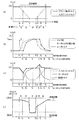
上記のモータ制御装置1を搭載した車両10の変速時におけるトルク及びクラッチストロークの経時変動を図3(a)〜(d)に例示する。時刻t0は変速機制御装置6からシフトチェンジ要求信号が出力された時刻であり、変速期間は時刻t0から時刻t6までの期間である。また、ここでは変速期間中のドライバ要求トルクTDが一定であるものとし、時刻t1〜t6はそれぞれ、制御ゾーンが第一ゾーン〜第六ゾーンのそれぞれを脱する時刻(終点の時刻)とする。なお、時刻t1〜t6は各ゾーンの定義によって変化するが、ここでは入力エンジントルクTEの値に基づいて各ゾーンが切り分けられているものとして説明する。
[4. Action]
[4-1. When setting the compensation rate by the input engine torque]
FIGS. 3A to 3D illustrate temporal variations in torque and clutch stroke at the time of shifting of the
エンジン制御装置5は、変速機制御装置6からのシフトチェンジ要求信号を受けて、エンジン11から出力されるトルクを若干減少させるようにエンジン11の運転状態を制御する。これにより、図3(a)に破線で示す入力エンジントルクTEが時刻t0から徐々に低下し、ドライバ要求トルクTDと比較して小さくなる。したがって変速開始時の制御ゾーンは第一ゾーンとなる。また、モータ制御装置1のトルク差演算部2では、ドライバ要求トルクTDと入力エンジントルクTEとのトルク差D及びその変化勾配GDが演算される。トルク差Dは、図3(b)に破線で示すように、時刻t0から徐々に増大する。
The
モータ制御部4では、トルク差Dに応じたモータトルクTMをモータ13に出力させるための指示値Sが演算される。このときの制御ゾーンは第一ゾーンであることから、補償率Kが1よりも大きな値に設定される。これにより、時刻t0の直後の指示値Sは、その変化勾配GSがトルク差Dの変化勾配GDよりも大きくなるように設定される。したがって、図3(b)に細実線で示すように、モータトルクTMの指示値Sは急勾配で増加する。
The
続いて入力エンジントルクTEがさらに減少し、時刻t1に制御ゾーンが第二ゾーンに突入すると、モータ制御部4で補償率Kが1よりも小さな値に設定される。これにより、モータトルクTMの指示値Sの変化勾配GSがトルク差Dの変化勾配GDよりも小さくなるように設定される。したがって、図3(b)に細実線で示すように、時刻t1以降の指示値Sの増加勾配は緩慢となる。
Then further decrease the input engine torque T E, the control zone at time t 1 rushes into the second zone, the compensation factor K is set to a value smaller than 1 in the
このような指示値Sの制御に対して、実際にモータ13からモータトルクTMが出力され始めるのは、図3(b)中に示すように、時刻t0から応答遅れ時間Pが経過した時刻tAである。また、自動変速機12から駆動輪14側に伝達される駆動トルクTWは、ギヤボックス12bに入力された入力エンジントルクTEとモータトルクTMとを加算したトルクである。したがって、図3(c)中に太実線で示すように、時刻t0から減少し始めた駆動トルクTWの変化方向は時刻tAに増大方向へと転じ、入力エンジントルクTEの不足分が迅速に補償される。
The control of such instruction value S, actually the motor torque T M from the
さらに、時刻t1から応答遅れ時間Pが経過した時刻tB以降はモータトルクTMの増加勾配が緩慢となるため、駆動トルクTWの増加量が抑えられ、過剰なトルクアシストが抑制される。これにより、図3(c)中に太実線で示すように、時刻tB以降では変速の開始前とほぼ同等の駆動トルクTWが実現され、クラッチ12aの開放に伴うトルク抜け感が大幅に減少する。 Furthermore, since the increase gradient of the motor torque T M becomes slow after the time t B when the response delay time P elapses from the time t 1, the increase amount of the drive torque T W is suppressed, and excessive torque assist is suppressed. . Thus, as indicated by the thick solid line in FIG. 3 (c), the at the time t B after approximately equal driving torque T W and before the start of the shift is realized, greatly sense of torque loss due to the opening of the clutch 12a Decrease.
なお、時刻t2の指示値Sに対応するモータトルクTMが発生するのは時刻t2から応答遅れ時間Pが経過した時刻tCであり、すなわちモータトルクTMがトルク差Dの変動に追いつくのは制御ゾーンが第三ゾーンに遷移した後である。しかしながら、本実施形態の制御では、第一ゾーンで設定される補償率Kが1よりも大きく、かつ、第二ゾーンで設定される補償率Kが1以下であるため、時刻tAから時刻tCまでの期間のうち、前半の期間でのモータトルクTMの上昇効率が向上する。したがって、図3(c)に示すように、制御ゾーンが第二ゾーンに位置する間に駆動トルクTWが変速開始前の大きさまで回復する。 Note that the motor torque T M corresponding to the indicated value S at time t 2 is generated at time t C when the response delay time P has elapsed from time t 2 , that is, the motor torque T M changes to the torque difference D. It catches up after the control zone transitions to the third zone. However, the control of this embodiment is greater compensation ratio K which is set in the first zone than 1, and, for compensating rate K set in the second zone is 1 or less, the time from the time t A t of time to C, increase the efficiency of the motor torque T M in the first half period is improved. Therefore, as shown in FIG. 3C, the drive torque TW is restored to the level before the start of the shift while the control zone is positioned in the second zone.
時刻t2に入力エンジントルクTEがTE=0になると制御ゾーンが第三ゾーンとなり、モータ制御部4で補償率KがK=1に設定される。これにより、モータトルクTMの指示値Sの変化勾配GSがトルク差Dの変化勾配GDと同一勾配となる。なお、第二ゾーン及び第三ゾーンでモータトルクTMがモータ13で出力可能な最大トルクTMMAXに達した場合には、その最大トルクTMMAXが第三ゾーンの終点まで維持される。
A control zone inputs engine torque T E is T E = 0 at time t 2 becomes the third zone, the compensation factor K is set to K = 1 in the
第三ゾーンでは、図3(d)に示すように、変速機制御装置6がクラッチ12aを開放方向に制御し、すなわちクラッチストロークを開放方向に移動させる。したがって、モータトルクTMのみが車両10の駆動トルクTWとなる。一方、このとき設定されている補償率KはK=1であるから、モータトルクTMの指示値Sの変化勾配GSはトルク差Dの変化勾配GDと同一勾配となり、すなわちドライバ要求トルクTDの変化勾配と同一となる。また、ドライバ要求トルクTDの値が一定であるとき、モータトルクTMはドライバ要求トルクTDに一致する。
In the third zone, as shown in FIG. 3D, the
ギヤボックス12b内での変速動作が完了すると、変速機制御装置6はクラッチ12aを係合方向に制御し、すなわちクラッチストロークを係合方向に移動させる。時刻t3に摩擦係合要素間でのトルク伝達が始まると、図3(a)に示すように、入力エンジントルクTEが徐々に増大する。このとき、制御ゾーンが第四ゾーンに設定されるとともに、トルク差D及びその変化勾配GDが演算される。第四ゾーンでは、トルク差Dの変化勾配GDが負となる。
また、モータ制御部4では補償率Kが1よりも大きな値に設定され、モータトルクTMの指示値Sが演算される。したがって、指示値Sの変化勾配GSは負の変化勾配GDをさらに大きくした傾きとなり、図3(b)に細実線で示すように、モータトルクTMの指示値Sは急勾配で減少する。
When the speed change operation in the
Furthermore, the compensation factor K in the
その後、クラッチ12aが徐々に係合するに連れて入力エンジントルクTEがさらに増大し、時刻t4に制御ゾーンが第五ゾーンに推移すると、モータ制御部4で補償率KがK=1に設定される。これにより、モータトルクTMの指示値Sの変化勾配GSがトルク差Dの変化勾配GDと同一勾配となる。さらに、時刻t5に制御ゾーンが第六ゾーンに到達すると、モータ制御部4で補償率Kが1よりも小さな値に設定される。これにより、モータトルクTMの指示値Sの変化勾配GSがトルク差Dの変化勾配GDよりも小さくなるように設定される。したがって、図3(b)に細実線で示すように、時刻t4以降の指示値Sの減少勾配は緩慢となり、時刻t5以降にはさらに緩やかとなる。時刻t6に入力エンジントルクTEがドライバ要求トルクTDに一致すると変速動作が完了し、制御ゾーンが第六ゾーンを脱する。
Thereafter, the clutch 12a is further increased input engine torque T E As the engaged gradually, the control zone at time t 4 is shifted to the fifth zone, the compensation factor K in the
なお、第四ゾーン及び第五ゾーンの途中で、エンジン11から出力されるトルクをやや増加させるように、エンジン制御装置5がエンジン11の運転状態を制御してもよい。例えば、変速開始時にエンジン11から出力されるトルクを若干減少させる制御を実施した場合には、その減少量と同量のトルクを増大させてもよい。
In the middle of the fourth zone and the fifth zone, the
上記の第四ゾーンから第六ゾーンまでの変速期間には、モータトルクTMが減少するようにモータ13が制御される。実際にモータ13から出力されるモータトルクTMは、その指示値Sに対して応答遅れ時間P分の遅れを持って変動する。すなわち、指示値Sの変化勾配GSが変化する時刻t3,t4,t5のそれぞれから応答遅れ時間Pが経過した時刻をtD,tE,tFとすると、モータトルクTMは時刻tD〜tE間に急勾配で減少し、時刻tE〜tF間では緩勾配で減少する。これにより、図3(c)中に太実線で示すように、時刻t3から増大し始めた駆動トルクTWの変化方向は時刻tDに減少方向へと転じ、入力エンジントルクTEの余剰分が相殺される。
The shift period from the fourth zone of the up sixth zone, the
一方、時刻tE以降にはモータトルクTMの減少勾配が緩やかになるため、駆動トルクTWの減少量が抑えられる。さらに、時刻tF以降になるとモータトルクTMがさらにゆっくりと減少し、駆動トルクTWの値が安定する。このように、第四ゾーンではトルクアシストが急激に削減されるとともに、その後の第五ゾーン及び第六ゾーンでは比較的小さなトルクアシスト量が変速期間の後期に至るまで温存され、トルクバランスが保たれる。これにより、図3(c)中に太実線で示すように、時刻tE以降では変速の開始前とほぼ同等の駆動トルクTWが実現され、クラッチ12aの係合に伴う車両10の押し出し感が解消される。
On the other hand, after time t E for decreasing gradient of the motor torque T M becomes gradual reduction amount of the driving torque T W is suppressed. Furthermore, the after time t F when the reduced motor torque T M is further slowly, the value of the driving torque T W is stabilized. Thus, in the fourth zone, torque assist is sharply reduced, and in the subsequent fifth and sixth zones, a relatively small amount of torque assist is maintained until the latter stage of the shift period, and the torque balance is maintained. It is. Thus, as indicated by the thick solid line in FIG. 3 (c), the at the time t E thereafter substantially equal driving torque T W and before the start of the shift is achieved, the extrusion feeling of the
[4−2.補償率を固定した比較例]
比較例として、上記のモータ制御装置1が補償率Kを全く変更しない場合についてのトルクの経時変動を図4(a),(b)に例示する。ここでは、変速期間の全期間にわたって補償率Kが一定(例えばK=1)であるものとする。また、クラッチ12aの挙動は、図3(d)に示すものと同一であり、入力エンジントルクTEも図3(a)中に破線で示すものと同様に変化するものと仮定する。
[4-2. Comparative example with fixed compensation rate]
As a comparative example, FIGS. 4A and 4B illustrate torque fluctuations over time when the
この場合、モータ制御部4で演算される指示値Sの変化勾配GSがトルク差Dの変化勾配GDと常に一致する。これにより、モータトルクTMの指示値Sは、図4(a)に示すように、トルク差Dの変化勾配GDと同一値に設定される。したがって、実際にモータ13から出力されるモータトルクTMは、図4(a)中に太実線で示すように、時刻t0から応答遅れ時間Pが経過した時刻tAに増加し始め、一定の勾配で増加する。駆動トルクTWの増加が停止するのは、時刻t2から応答遅れ時間Pが経過した時刻tCとなる。
In this case, the change gradient G S of the instruction value S calculated by the
一方、自動変速機12から駆動輪14側に伝達される駆動トルクTWは、入力エンジントルクTEとモータトルクTMとの和として与えられるため、図4(b)中に太実線で示すように変動する。補償率KがK=1であることからモータトルクTMの変化勾配は入力エンジントルクTEの変化勾配と逆符号の同一値となる。したがって、これらの二つのトルクが共に変動する時刻tAから時刻t2までの期間では、モータトルクTMが入力エンジントルクTEの減少分のみを補うように作用し、駆動トルクTWの値が変速開始前よりも小さい所定値TXで均衡する。その結果、時刻t0から時刻tCまでの長期間にわたって駆動トルクTWが不足した状態となり、クラッチ12aの開放に伴うトルク抜け感が発生する。
On the other hand, the drive torque T W transmitted from the
また、クラッチ12aの係合時には、入力エンジントルクTEが上昇し始める時刻t3から応答遅れ時間Pが経過した時刻tDにモータトルクTMが減少し始めるため、駆動トルクTWの値が変速開始前よりも大きい所定値TYで均衡する。時刻t6から応答遅れ時間Pが経過した時刻をtGとすると、駆動トルクTWは時刻t3から時刻tGまでの長時間にわたって過剰な状態となり、クラッチ12aの係合に伴う押し出し感が発生する。 Further, at the time of engagement of the clutch 12a, for the time t D in the motor torque T M of the input engine torque T E has passed the response delay time P from a time t 3 when starts to rise begins to decrease, the value of the driving torque T W Equilibrium is performed at a predetermined value TY that is larger than that before the start of shifting. Assuming that the time at which the response delay time P has elapsed from time t 6 is t G , the driving torque T W becomes excessive for a long time from time t 3 to time t G, and the feeling of extrusion accompanying the engagement of the clutch 12 a is felt. Occur.
このように、モータトルクTMの発生に先行して補償率Kを1よりも大きく設定する第一制御と、その後に補償率Kを1以下に設定する第二制御とを実施することで、駆動トルクTWのドライバ要求トルクTDへの収束速度が向上し、クラッチ12aの変速動作に伴うトルク抜け感や押し出し感が解消される。上記の図4(b)中に太実線で示された駆動トルクTWのグラフ形状と、図3(c)中に太実線で示された駆動トルクTWのグラフ形状との差異は、モータ制御部4における補償率Kの設定手法に由来するものである。
In this manner, by carrying out a first control to greater than 1 prior to compensation ratio K to the generation of the motor torque T M, and a second control that sets the
[5.効果]
(1)上記のモータ制御装置1では、クラッチ12aの開放過程における第一ゾーンでモータトルクTMの指示値Sの変化勾配GSがトルク差Dの変化勾配GDよりも大きく急勾配に設定される。また、その後の第二ゾーンでは、変化勾配GSがトルク差Dの変化勾配GDよりも小さく緩勾配に設定される。
クラッチ12aの係合過程においても同様であり、第四ゾーンではモータトルクTMの指示値Sの変化勾配GSがトルク差Dの変化勾配GDよりも大きく急勾配に設定され、その後の第五ゾーン及び第六ゾーンでは小さく緩勾配に設定される。
[5. effect]
(1) In the
The same is true in the engagement process of the clutch 12a, is set steeper greater than the change gradient G D changes the gradient G S torque difference D instruction value S in the fourth zone motor torque T M, then the first In the fifth zone and the sixth zone, a small and gentle slope is set.
このような変化勾配GSの緩急の順序設定により、図3(c)に示すように、モータ13の応答遅れと、クラッチ12aの断接に伴う駆動トルクの変動幅及び変動時間を減少させることができる。
例えば、入力エンジントルクTEの立ち下がり時には、モータトルクTMのアシスト遅れによるトルク抜け感を低減させることができる。あるいは、入力エンジントルクTEの立ち上がり時には、モータトルクTMの残留による車両の押し出し感を低減させることができる。これにより、ドライブフィーリングを向上させることができる。
As shown in FIG. 3C, the gradual setting of the change gradient G S reduces the response delay of the
For example, at the falling edge of the input engine torque T E may be reduced feeling loss torque by the assist delay of the motor torque T M. Alternatively, when the rise of the input engine torque T E, it is possible to reduce the extrusion feeling of the vehicle due to the residual of the motor torque T M. Thereby, drive feeling can be improved.
(2)また、上記のモータ制御装置1では、トルク差Dが増加し始める時刻t0が第一ゾーンの始点とされ、またトルク差Dが減少し始める時刻t3が第四ゾーンの始点とされている。そして、これらの第一ゾーン,第四ゾーンで設定される補償率Kの値は、何れのゾーンであっても1よりも大きな値とされている。つまり、上記のモータ制御装置1では、トルク差Dの変動開始時に第一制御が実施され、モータトルクTMの変化速度が速くなるようにモータ13への指示値Sが制御される。これにより、モータトルクTMの立ち上がりや立ち下がりの初期の制御量が増幅されることになり、モータ13の応答遅れによるトルク変動が抑制されるまでにかかる時間を短縮することができ、迅速にトルク変動を抑制することができる。
(2) In the
(3)また、上記のモータ制御装置1では、補償率Kを用いてモータトルクTMの指示値Sの変化勾配GSを制御している。補償率Kはトルク差Dの変化勾配GDに対するモータトルクTMの指示値Sの変化勾配GSの比に相当するパラメーターであるから、トルク差Dの変化勾配GDに補償率Kを乗じた値が指示値Sの変化勾配GSとなる。このように、補償率Kを用いることで演算構成を簡素化することができ、容易にモータトルクTMの指示値Sの変化勾配GSを切り換えることができる。
(3) In the
(4)さらに、上記のモータ制御装置1では、入力エンジントルクTEの値に基づいて第一ゾーンから第六ゾーンまでの各ゾーンが切り分けられている。つまり、入力エンジントルクTEの値に基づいて補償率Kが設定され、モータトルクTMの指示値Sの変化勾配GSが切り換えられることになる。このように、ギヤボックス12bに入力されるエンジントルクの大きさに応じてモータ13を制御することにより、クラッチ12aの断接状態に適合するようにモータトルクTMの出力を調整することが可能となり、駆動トルクTWのドライバ要求トルクTDに対する追従性を向上させることができる。
(4) Further, in the
[6.変形例]
上述した実施形態に関わらず、それらの趣旨を逸脱しない範囲で種々変形して実施することができる。本実施形態の各構成は、必要に応じて取捨選択することができ、あるいは適宜組み合わせてもよい。
例えば、上述の実施形態では、表1に示すように、制御ゾーン毎に予め補償率Kの値が設定されたものを例示したが、変速状態に応じて補償率Kの値を変更する制御構成としてもよい。この場合、少なくとも補償率Kが1よりも大きい制御期間を設けるとともに、補償率Kが1以下となる制御期間をその後に設ければよい。
[6. Modified example]
Regardless of the embodiment described above, various modifications can be made without departing from the spirit of the invention. Each structure of this embodiment can be selected as needed, or may be combined appropriately.
For example, in the above-described embodiment, as illustrated in Table 1, the example in which the value of the compensation rate K is set in advance for each control zone is illustrated, but the control configuration in which the value of the compensation rate K is changed according to the shift state. It is good. In this case, at least a control period in which the compensation rate K is greater than 1 is provided, and a control period in which the compensation rate K is 1 or less is provided thereafter.
また、上述の実施形態では、図3(a)に示すように、入力エンジントルクTEの値に応じて制御ゾーンが識別され、各々の制御ゾーンに対応する補償率Kが設定されるものを例示したが、制御ゾーンの識別手法や補償率Kの設定手法はこれに限定されない。
具体的には、第二ゾーンや第三ゾーン,第五ゾーン,第六ゾーン等の識別にモータトルクTMを用いてもよい。この場合、実際にモータ13から出力されたモータトルクTM(すなわちモータトルク応答値)が所定値以上になったことを以て、制御ゾーンが移行したと判断することが考えられる。モータトルクTMの値に基づいてその指示値Sの変化勾配GSを切り換えることにより、モータ13の最大出力能力に合わせて第一制御や第二制御を実施することができる。例えば、モータトルクTMが最大トルクTMMAXに達する時刻と第三ゾーンの終点に対応する時刻とが一致するように、第二制御での変化勾配GSを微調整することができ、駆動トルクTWのドライバ要求トルクTDに対する追従性をさらに向上させることができる。
In the aforementioned embodiment, as shown in FIG. 3 (a), identifies the control zone in accordance with the value of the input engine torque T E, what compensation rate K corresponding to each of the control zones is set Although illustrated, the method for identifying the control zone and the method for setting the compensation rate K are not limited to this.
Specifically, the second zone and the third zone, the fifth zone may be used motor torque T M in the identification of such sixth zone. In this case, it may be determined that the control zone has shifted when the motor torque T M (that is, the motor torque response value) actually output from the
あるいは、第一ゾーンや第二ゾーン,第四ゾーン,第五ゾーン等を識別する際に、トルク差Dの変動開始時からの経過時間を参照する制御構成としてもよい。例えば、時刻t0から所定の第一制御時間が経過したことを以て、第一ゾーンから第二ゾーンへと移行したと判断することが考えられる。トルク差Dが変動を開始した時点からの経過時間に基づいてモータトルクTMの指示値Sの変化勾配GSを切り換えることにより、変速動作の進行速度に関わらず、モータ13の応答遅れを取り戻すためのトルクを自動変速機12に付与することができる。なお、上記の第一制御時間は、その期間内に設定される補償率Kが大きいほど短く設定することが可能である。
Alternatively, the control configuration may be such that when the first zone, the second zone, the fourth zone, the fifth zone, etc. are identified, the elapsed time from the start of the fluctuation of the torque difference D is referred to. For example, it may be determined that the transition from the first zone to the second zone is made when a predetermined first control time has elapsed from time t 0 . By switching the change gradient G S of the instruction value S of the motor torque T M based on the elapsed time from the time when the torque difference D starts to fluctuate, the response delay of the
また、上述の実施形態では、モータ制御装置1がエンジン制御装置5や変速機制御装置6からドライバ要求トルクTD,入力エンジントルクTE等の情報を取得するものを例示したが、これらのトルクの具体的な取得手法は任意である。例えば、アクセル操作量やエンジン11の実回転数Ne等に基づいて、モータ制御装置1がドライバ要求トルクTDの値を演算する構成としてもよいし、入力エンジントルクTEについても同様である。
Further, in the above-described embodiment, the
1 モータ制御装置
2 トルク差演算部(演算手段)
3 ゾーン判定部
4 モータ制御部(制御手段)
10 車両
11 エンジン
12 自動変速機
12a クラッチ
12b ギヤボックス(変速機)
13 モータ
14 駆動輪
DESCRIPTION OF
3
10
13
Claims (6)
前記車両に対する要求トルクと前記変速機に入力されるエンジントルクとのトルク差を演算する演算手段と、
前記トルク差に応じた前記モータトルクを前記モータに出力させる制御手段とを備え、
前記制御手段が、
前記モータトルクの指示値の変化勾配を前記トルク差の変化勾配よりも大きく設定する第一制御と、
前記第一制御の後に前記モータトルクの指示値の変化勾配を前記トルク差の変化勾配以下に設定する第二制御とを実施する
ことを特徴とする、車両の変速制御装置。 A shift control device for a vehicle, comprising: an engine connected to a transmission via a clutch; and a motor for supplying motor torque to drive wheels for equalizing torque fluctuations associated with connection and disconnection of the clutch,
A calculation means for calculating a torque difference between a required torque for the vehicle and an engine torque input to the transmission;
Control means for causing the motor to output the motor torque corresponding to the torque difference,
The control means is
A first control for setting a change gradient of the indicated value of the motor torque to be larger than a change gradient of the torque difference;
And a second control for setting a change gradient of the indicated value of the motor torque to be equal to or less than the change gradient of the torque difference after the first control.
ことを特徴とする、請求項1記載の車両の変速制御装置。 2. The vehicle shift control device according to claim 1, wherein the control means performs the first control at the start of fluctuation of the torque difference.
前記トルク差の変化勾配に対する前記モータトルクの指示値の変化勾配の比を補償率として演算し、
前記第一制御時の前記補償率を1よりも大きく設定するとともに、
前記第二制御時の前記補償率を1以下に設定する
ことを特徴とする、請求項1又は2記載の車両の変速制御装置。 The control means is
The ratio of the change gradient of the indicated value of the motor torque to the change gradient of the torque difference is calculated as a compensation rate,
While setting the compensation rate during the first control larger than 1,
The shift control apparatus for a vehicle according to claim 1 or 2, wherein the compensation rate during the second control is set to 1 or less.
ことを特徴とする、請求項1〜3の何れか1項に記載の車両の変速制御装置。 The said control means refers to the value of the engine torque input into the said transmission as switching conditions from said 1st control to said 2nd control, The any one of Claims 1-3 characterized by the above-mentioned. The gear shift control device for a vehicle according to 1.
ことを特徴とする、請求項1〜4の何れか1項に記載の車両の変速制御装置。 The vehicle shift according to any one of claims 1 to 4, wherein the control means refers to the value of the motor torque as a switching condition from the first control to the second control. Control device.
ことを特徴とする、請求項1〜5の何れか1項に記載の車両の変速制御装置。 The said control means refers to the elapsed time from the time of the fluctuation | variation start of the said torque difference as switching conditions from said 1st control to said 2nd control, The any one of Claims 1-5 characterized by the above-mentioned. The gear shift control device for a vehicle according to 1.
Priority Applications (1)
| Application Number | Priority Date | Filing Date | Title |
|---|---|---|---|
| JP2011209277A JP2013067352A (en) | 2011-09-26 | 2011-09-26 | Speed change control device of vehicle |
Applications Claiming Priority (1)
| Application Number | Priority Date | Filing Date | Title |
|---|---|---|---|
| JP2011209277A JP2013067352A (en) | 2011-09-26 | 2011-09-26 | Speed change control device of vehicle |
Publications (1)
| Publication Number | Publication Date |
|---|---|
| JP2013067352A true JP2013067352A (en) | 2013-04-18 |
Family
ID=48473579
Family Applications (1)
| Application Number | Title | Priority Date | Filing Date |
|---|---|---|---|
| JP2011209277A Withdrawn JP2013067352A (en) | 2011-09-26 | 2011-09-26 | Speed change control device of vehicle |
Country Status (1)
| Country | Link |
|---|---|
| JP (1) | JP2013067352A (en) |
Cited By (2)
| Publication number | Priority date | Publication date | Assignee | Title |
|---|---|---|---|---|
| CN107200021A (en) * | 2016-03-16 | 2017-09-26 | 福特全球技术公司 | The method and apparatus longitudinally controlled for motor vehicles |
| WO2022143305A1 (en) * | 2020-12-28 | 2022-07-07 | 长城汽车股份有限公司 | Hybrid vehicle torque control method and apparatus, storage medium, and electronic device |
-
2011
- 2011-09-26 JP JP2011209277A patent/JP2013067352A/en not_active Withdrawn
Cited By (3)
| Publication number | Priority date | Publication date | Assignee | Title |
|---|---|---|---|---|
| CN107200021A (en) * | 2016-03-16 | 2017-09-26 | 福特全球技术公司 | The method and apparatus longitudinally controlled for motor vehicles |
| WO2022143305A1 (en) * | 2020-12-28 | 2022-07-07 | 长城汽车股份有限公司 | Hybrid vehicle torque control method and apparatus, storage medium, and electronic device |
| US12202463B2 (en) | 2020-12-28 | 2025-01-21 | Great Wall Motor Company Limited | Method for torque control of hybrid vehicle, storage medium and electronic device |
Similar Documents
| Publication | Publication Date | Title |
|---|---|---|
| US10099693B2 (en) | Control method of dual clutch transmission for hybrid electric vehicle and control system for the same | |
| US7645209B2 (en) | Method for operating a parallel hybrid powertrain | |
| CN106560362B (en) | Control method and control system for dual clutch transmission of hybrid electric vehicle | |
| KR101427932B1 (en) | Shift control method and system of hybrid electric vehicle including motor speed control | |
| US9937925B2 (en) | Shift control method for hybrid vehicle with DCT | |
| JP5482907B2 (en) | Drive torque control device for hybrid vehicle | |
| JP5223603B2 (en) | Control device for hybrid vehicle | |
| US20120130579A1 (en) | Method and device for determining the beginning of a start phase of an internal combustion engine in a hybrid vehicle | |
| JP5746376B2 (en) | Hybrid electric vehicle controller and hybrid electric vehicle control method | |
| JP2013107543A (en) | Control device | |
| JP2013056587A (en) | Vehicle brake control device | |
| JP5727035B2 (en) | Control device for automatic transmission | |
| JP5716914B2 (en) | Control device for hybrid vehicle | |
| JP2009051403A (en) | Controller for vehicle and control system | |
| KR102383229B1 (en) | Method and apparatus for learning clutch pedal | |
| JP6702085B2 (en) | Electric vehicle control method and electric vehicle control device | |
| JP2013067352A (en) | Speed change control device of vehicle | |
| JP2013245590A (en) | Vehicle transmission control system | |
| JP5335021B2 (en) | Method for controlling a drive train of an automobile having an automatic clutch | |
| KR20200123298A (en) | Control method for power-off downshift of hybrid electric vehicle | |
| JP5954035B2 (en) | Shift control device and shift control method for automatic transmission | |
| CN113785143B (en) | Shift control method and shift control system | |
| JP6477177B2 (en) | Control device for hybrid vehicle | |
| JP2013188073A (en) | Rotation control device of motor | |
| US10723355B1 (en) | Vehicle start control method |
Legal Events
| Date | Code | Title | Description |
|---|---|---|---|
| A300 | Withdrawal of application because of no request for examination |
Free format text: JAPANESE INTERMEDIATE CODE: A300 Effective date: 20141202 |