JP2013058280A - Disk conveying device - Google Patents
Disk conveying device Download PDFInfo
- Publication number
- JP2013058280A JP2013058280A JP2011195512A JP2011195512A JP2013058280A JP 2013058280 A JP2013058280 A JP 2013058280A JP 2011195512 A JP2011195512 A JP 2011195512A JP 2011195512 A JP2011195512 A JP 2011195512A JP 2013058280 A JP2013058280 A JP 2013058280A
- Authority
- JP
- Japan
- Prior art keywords
- recording medium
- shaped recording
- disc
- disk
- rotated
- Prior art date
- Legal status (The legal status is an assumption and is not a legal conclusion. Google has not performed a legal analysis and makes no representation as to the accuracy of the status listed.)
- Abandoned
Links
Images


Classifications
-
- G—PHYSICS
- G11—INFORMATION STORAGE
- G11B—INFORMATION STORAGE BASED ON RELATIVE MOVEMENT BETWEEN RECORD CARRIER AND TRANSDUCER
- G11B17/00—Guiding record carriers not specifically of filamentary or web form, or of supports therefor
- G11B17/02—Details
- G11B17/04—Feeding or guiding single record carrier to or from transducer unit
-
- G—PHYSICS
- G11—INFORMATION STORAGE
- G11B—INFORMATION STORAGE BASED ON RELATIVE MOVEMENT BETWEEN RECORD CARRIER AND TRANSDUCER
- G11B17/00—Guiding record carriers not specifically of filamentary or web form, or of supports therefor
- G11B17/22—Guiding record carriers not specifically of filamentary or web form, or of supports therefor from random access magazine of disc records
- G11B17/221—Guiding record carriers not specifically of filamentary or web form, or of supports therefor from random access magazine of disc records with movable magazine
- G11B17/223—Guiding record carriers not specifically of filamentary or web form, or of supports therefor from random access magazine of disc records with movable magazine in a vertical direction
Abstract
Description
本技術はディスク搬送装置についての技術分野に関する。詳しくは、搬送されるディスク状記録媒体に押圧されて回動されるルートアジャスターによってディスク状記録媒体の位置決めを行い機構の簡素化を確保した上でディスク状記録媒体の搬送時における位置精度の向上を図る技術分野に関する。 The present technology relates to the technical field of a disk transport device. Specifically, positioning of the disk-shaped recording medium is ensured by a route adjuster that is pressed and rotated by the disk-shaped recording medium to be transported to ensure the simplification of the mechanism, and the positional accuracy during the transportation of the disk-shaped recording medium is improved. This is related to the technical field.
画像データーや音声データーが記録されるディスク状記録媒体を搬送するディスク搬送装置がある。 There is a disk transport device that transports a disk-shaped recording medium on which image data and audio data are recorded.
このようなディスク搬送装置には、一対のアーム部と各アーム部の先端部にそれぞれ樹脂材料によって形成された係止爪が取り付けられ、一対の係止爪によってディスク状記録媒体を外周側から挟持してアーム部を動作させることによりディスク状記録媒体を所定の方向へ搬送するように構成されたものがある(例えば、特許文献1参照)。 In such a disc transport device, a pair of arm portions and a locking claw formed of a resin material are attached to the tip of each arm portion, and the disc-shaped recording medium is sandwiched from the outer peripheral side by the pair of locking claws. Then, there is one configured to convey a disc-shaped recording medium in a predetermined direction by operating the arm portion (see, for example, Patent Document 1).
特許文献1に記載されたディスク搬送装置にあっては、一対のアーム部に取り付けられた係止爪によってディスク状記録媒体が外周側から挟持されて保持され、アーム部が動作されて、例えば、ディスクカートリッジに収納される。
In the disc transport device described in
ところが、特許文献1に記載されたディスク搬送装置にあっては、一対のアーム部及び各アーム部に取り付けられた係止爪によってディスク状記録媒体を外周側から保持して搬送するが、各部の組付精度等によってディスク状記録媒体が適正な位置からずれて保持される可能性があり、保持状態によってはディスク状記録媒体がディスクカートリッジに対して適正に収納されないおそれがある。
However, in the disc transport apparatus described in
この場合に、ディスク状記録媒体をディスクカートリッジに収納する際に、ディスク状記録媒体をディスクカートリッジ対して適正な位置に位置決めする位置決め機構を設けることが考えられるが、位置決め機構の構成によってはディスク搬送装置に設けられる機構が複雑になると言う問題が生じてしまう。 In this case, it is conceivable to provide a positioning mechanism for positioning the disk-shaped recording medium at an appropriate position with respect to the disk cartridge when the disk-shaped recording medium is stored in the disk cartridge. There arises a problem that the mechanism provided in the apparatus becomes complicated.
そこで、本技術ディスク搬送装置は、上記した問題点を克服し、機構の簡素化を確保した上でディスク状記録媒体の搬送時における位置精度の向上を図ることを課題とする。 Accordingly, an object of the disk transport device according to the present technology is to overcome the above-described problems and to improve the positional accuracy during transport of the disk-shaped recording medium while ensuring simplification of the mechanism.
第1に、ディスク搬送装置は、上記した課題を解決するために、ディスクカートリッジから引き出されて引き込まれる引込方向又は排出されてディスクカートリッジに収納される排出方向へ中心軸方向に直交する方向において搬送されるディスク状記録媒体によって押圧されて回動されるルートアジャスターを備え、前記ルートアジャスターに前記ディスク状記録媒体の搬送時に前記ディスク状記録媒体の外周部が挿入されて前記ディスク状記録媒体の位置決めを行う位置決め溝が形成されたものである。 First, in order to solve the above-described problems, the disk transport device transports in a direction perpendicular to the central axis direction in a pull-in direction in which the disk is pulled out and pulled in from the disk cartridge or a discharge direction in which the disk is ejected and stored in the disk cartridge. And a root adjuster that is pressed and rotated by the disc-shaped recording medium, and the outer periphery of the disc-shaped recording medium is inserted into the root adjuster when the disc-shaped recording medium is transported to position the disc-shaped recording medium. Positioning grooves for performing the above are formed.
従って、ディスク搬送装置にあっては、搬送されるディスク状記録媒体によってルートアジャスターが回動されるときにルートアジャスターによってディスク状記録媒体が位置決めされる。 Therefore, in the disk transport device, the disk-shaped recording medium is positioned by the root adjuster when the root adjuster is rotated by the transported disk-shaped recording medium.
第2に、上記したディスク搬送装置においては、前記ディスクカートリッジに複数の前記ディスク状記録媒体がそれぞれ収納可能な複数の保持溝が前記ディスク状記録媒体の中心軸方向に並んで形成され、前記ルートアジャスターに、前記ディスク状記録媒体が前記排出方向へ搬送されて回動されたときに前記ディスク状記録媒体が挿入される保持溝と異なる保持溝に挿入されて前記ルートアジャスターの前記ディスクカートリッジに対する位置決めを行う位置決め用突部を設けることが望ましい。 Second, in the above-described disk transport device, a plurality of holding grooves that can store a plurality of the disk-shaped recording media in the disk cartridge are formed side by side in the central axis direction of the disk-shaped recording medium, and the route Positioning the root adjuster with respect to the disk cartridge by inserting the disc-shaped recording medium into a holding groove different from the holding groove into which the disk-shaped recording medium is inserted when the disk-shaped recording medium is conveyed and rotated in the ejecting direction. It is desirable to provide a positioning projection for performing the above.
ルートアジャスターにディスク状記録媒体が挿入される保持溝と異なる保持溝に挿入されてルートアジャスターのディスクカートリッジに対する位置決めを行う位置決め用突部を設けることにより、ディスク状記録媒体の挿入と位置決め用突部の挿入がディスクカートリッジの異なる保持溝に対して行われる。 Insertion of the disk-shaped recording medium and positioning protrusion by providing a positioning protrusion for positioning the root adjuster with respect to the disk cartridge by being inserted into a holding groove different from the holding groove into which the disk-shaped recording medium is inserted into the root adjuster Is inserted into different holding grooves of the disk cartridge.
第3に、上記したディスク搬送装置においては、前記ルートアジャスターの位置決め用突部が、前記保持溝を形成する面に押し付けられるようにすることが望ましい。 Third, in the disk transport device described above, it is desirable that the positioning protrusion of the route adjuster be pressed against the surface forming the holding groove.
ルートアジャスターの位置決め用突部が、保持溝を形成する面に押し付けられるようにすることにより、位置決め用突部保持溝を形成する面に押し付けられてルートアジャスターがディスクカートリッジに対する位置決めされる。 By positioning the positioning protrusion of the route adjuster against the surface forming the holding groove, the route adjuster is pressed against the surface forming the positioning protrusion holding groove to position the root adjuster relative to the disk cartridge.
第4に、上記したディスク搬送装置においては、前記位置決め用突部に、前記ルートアジャスターの回動時に前記保持溝を形成する面に摺動され前記摺動される面に対して傾斜された被案内面を形成することが望ましい。 Fourth, in the above-described disk transport device, the positioning projection is slid on the surface that forms the holding groove when the route adjuster is rotated, and is tilted with respect to the sliding surface. It is desirable to form a guide surface.
位置決め用突部に、ルートアジャスターの回動時に保持溝を形成する面に摺動され摺動される面に対して傾斜された被案内面を形成することにより、被案内面がディスクカートリッジに案内されて位置決め用突部が保持溝に位置決めされた状態で挿入される。 The guided surface is guided to the disk cartridge by forming a guided surface inclined on the surface that is slid and slid on the surface that forms the holding groove when the root adjuster is rotated on the positioning protrusion. Then, the positioning projection is inserted in a state of being positioned in the holding groove.
第5に、上記したディスク搬送装置においては、前記ルートアジャスターが中立位置を基準として反対方向へ回動可能とされ、前記位置決め溝が前記ルートアジャスターの外周面に二つ形成され、前記ディスク状記録媒体の前記引込方向への搬送時に前記ルートアジャスターが中立位置を基準として一方へ回動されて前記ディスク状記録媒体の外周部が一方の前記位置決め溝に挿入され、前記ディスク状記録媒体の前記排出方向への搬送時に前記ルートアジャスターが中立位置を基準として他方へ回動されて前記ディスク状記録媒体の外周部が他方の前記位置決め溝に挿入されるようにすることが望ましい。 Fifth, in the disk transport device described above, the route adjuster can be rotated in the opposite direction with respect to the neutral position, and two positioning grooves are formed on the outer peripheral surface of the route adjuster. When the medium is transported in the pull-in direction, the route adjuster is rotated to one side with respect to the neutral position, and the outer periphery of the disk-shaped recording medium is inserted into one of the positioning grooves, and the discharge of the disk-shaped recording medium is performed. It is desirable that the route adjuster is rotated to the other side with respect to the neutral position during conveyance in the direction so that the outer peripheral portion of the disc-shaped recording medium is inserted into the other positioning groove.
ルートアジャスターが中立位置を基準として反対方向へ回動可能とされ、位置決め溝がルートアジャスターの外周面に二つ形成されることにより、ディスク状記録媒体のディスク搬送装置に対する引込方向及び排出方向への搬送時に何れもディスク状記録媒体が位置決め溝に挿入されて位置決めされる。 The root adjuster can be rotated in the opposite direction with respect to the neutral position, and two positioning grooves are formed on the outer peripheral surface of the root adjuster, so that the disc-shaped recording medium can be pulled in and out of the disc transport device. In both cases, the disk-shaped recording medium is inserted into the positioning groove for positioning.
第6に、上記したディスク搬送装置においては、前記ルートアジャスターが前記中立位置を基準として一方及び他方へ回動されたときに前記ルートアジャスターを前記中立位置まで回動させる戻しバネを設けることが望ましい。 Sixth, in the disk transport device described above, it is desirable to provide a return spring that rotates the route adjuster to the neutral position when the route adjuster is rotated to one or the other with respect to the neutral position. .
ルートアジャスターが中立位置を基準として一方及び他方へ回動されたときにルートアジャスターを中立位置まで回動させる戻しバネを設けることにより、ディスク状記録媒体のディスク搬送装置に対する引込方向及び排出方向への搬送時に何れもルートアジャスターが戻しバネによって中立位置に回動される。 By providing a return spring that rotates the route adjuster to the neutral position when the route adjuster is rotated to one or the other with respect to the neutral position, the disk-shaped recording medium can be pulled in and out of the disk transport device. In any case, the route adjuster is rotated to the neutral position by the return spring during the conveyance.
第7に、上記したディスク搬送装置においては、前記位置決め溝に前記ディスク状記録媒体を案内する案内面を形成することが望ましい。 Seventhly, in the above-described disk transport device, it is desirable to form a guide surface for guiding the disk-shaped recording medium in the positioning groove.
位置決め溝にディスク状記録媒体を案内する案内面を形成することにより、ディスク状記録媒体が案内面に案内されて位置決め溝に挿入される。 By forming a guide surface for guiding the disc-shaped recording medium in the positioning groove, the disc-shaped recording medium is guided by the guide surface and inserted into the positioning groove.
第8に、上記したディスク搬送装置においては、ディスク状記録媒体の搬送方向に延び搬送される前記ディスク状記録媒体を挟んで反対側に位置される一対のレールと、前記一対のレールに回動可能に連結されて前記一対のレールを前記ディスク状記録媒体の外周面に離接する方向へ平行移動させる複数のリンクアームと、少なくとも一方の前記レールに回動自在に支持され回動されることにより前記ルートアジャスターによって位置決めされた前記ディスク状記録媒体の外周面を押圧して前記ディスク状記録媒体を前記ディスクカートリッジに収納する排出レバーとを設け、前記複数のリンクアームの少なくとも一つに引掛部を設け、前記ルートアジャスターに前記引掛部に係合可能な係合部を設け、前記ディスク状記録媒体が前記ディスクカートリッジに収納され前記排出レバーが前記ディスク状記録媒体を押圧する方向と反対方向へ回動されたときに前記リンクアームが前記排出レバーと同じ方向へ回動され、前記位置決め用突部が前記保持溝に挿入された状態において前記排出レバーが前記反対方向へ回動されて前記リンクアームが前記排出レバーと同じ方向へ回動されたときに前記引掛部が前記係合部に係合可能とされ、前記引掛部が前記係合部に係合したときに前記ルートアジャスターが前記リンクアームの回動動作に伴って前記中立位置へ向けて回動されるようにすることが望ましい。 Eighth, in the disk transport device described above, a pair of rails positioned on opposite sides of the disk-shaped recording medium that is transported extending in the transport direction of the disk-shaped recording medium, and pivoted to the pair of rails A plurality of link arms that are connected to each other and translate the pair of rails in a direction to move away from and contact the outer peripheral surface of the disk-shaped recording medium; and at least one of the rails is rotatably supported and rotated. A discharge lever that presses an outer peripheral surface of the disk-shaped recording medium positioned by the route adjuster and stores the disk-shaped recording medium in the disk cartridge; and a hook portion is provided on at least one of the plurality of link arms. An engagement portion that can engage with the hook portion is provided on the route adjuster, and the disc-shaped recording medium is The link arm is rotated in the same direction as the discharge lever when the discharge lever is stored in a cartridge and the discharge lever is rotated in a direction opposite to the direction in which the disc-shaped recording medium is pressed, and the positioning projection is held by the holding lever. When the discharge lever is rotated in the opposite direction in the state of being inserted into the groove and the link arm is rotated in the same direction as the discharge lever, the hook portion can be engaged with the engagement portion. It is preferable that the route adjuster is rotated toward the neutral position in accordance with the rotation operation of the link arm when the hooking portion is engaged with the engaging portion.
引掛部が係合部に係合可能とされ、引掛部が係合部に係合したときにルートアジャスターがリンクアームの回動動作に伴って中立位置へ向けて回動されるようにすることにより、ルートアジャスターのディスクカートリッジに対する回動状態に拘わらずルートアジャスターが中立位置まで回動される。 The hook portion is engageable with the engaging portion, and the route adjuster is rotated toward the neutral position along with the rotation of the link arm when the hook portion is engaged with the engaging portion. Thus, the route adjuster is rotated to the neutral position regardless of the rotation state of the route adjuster with respect to the disk cartridge.
第9に、上記したディスク搬送装置においては、前記排出レバーが前記ルートアジャスターと同じ方向へ回動可能とされ、前記ルートアジャスターの回動中心と前記排出レバーの回動中心とが前記回動中心に直交する方向において異なる位置に存在し、前記排出レバーの前記反対方向への回動時に係合された前記引掛部と前記係合部が摺動され前記排出レバーと前記ルートアジャスターが所定の位置に回動されたときに前記引掛部と前記係合部の係合が解除されるようにすることが望ましい。 Ninthly, in the above-described disk transport device, the discharge lever can be rotated in the same direction as the route adjuster, and the rotation center of the route adjuster and the rotation center of the discharge lever are the rotation centers. Are located at different positions in the direction orthogonal to the engagement portion, and the engagement portion and the engagement portion that are engaged when the discharge lever is rotated in the opposite direction are slid so that the discharge lever and the route adjuster are in a predetermined position. It is desirable that the engagement between the hook portion and the engaging portion is released when the hook is rotated.
排出レバーの反対方向への回動時に係合された引掛部と係合部が摺動され排出レバーとルートアジャスターが所定の位置に回動されたときに引掛部と係合部の係合が解除されるようにすることにより、ルートアジャスターが中立位置まで回動されると共にリンクアームが所定の位置まで回動される。 When the ejecting lever is rotated in the opposite direction, the engaging part and the engaging part are slid and the engaging part is engaged when the ejecting lever and the route adjuster are rotated to a predetermined position. By releasing, the route adjuster is rotated to the neutral position and the link arm is rotated to the predetermined position.
本技術ディスク搬送装置は、ディスクカートリッジから引き出されて引き込まれる引込方向又は排出されてディスクカートリッジに収納される排出方向へ中心軸方向に直交する方向において搬送されるディスク状記録媒体によって押圧されて回動されるルートアジャスターを備え、前記ルートアジャスターに前記ディスク状記録媒体の搬送時に前記ディスク状記録媒体の外周部が挿入されて前記ディスク状記録媒体の位置決めを行う位置決め溝が形成されている。 The disc transport device according to the present technology is rotated by being pressed by a disc-shaped recording medium that is transported in a direction perpendicular to the central axis direction in a pull-in direction in which the disc cartridge is pulled out and pulled out or stored in the disc cartridge. The route adjuster is moved, and a positioning groove for positioning the disc-shaped recording medium is formed by inserting an outer peripheral portion of the disc-shaped recording medium into the route adjuster when the disc-shaped recording medium is conveyed.
従って、ディスク状記録媒体を位置決めするための構成がルートアジャスターと言う簡素な部材によって構成され、機構の簡素化を確保した上でディスク状記録媒体の搬送時における位置精度の向上を図ることができる。 Therefore, the configuration for positioning the disk-shaped recording medium is configured by a simple member called a route adjuster, and the positional accuracy during the conveyance of the disk-shaped recording medium can be improved while ensuring the simplification of the mechanism. .
請求項2に記載した技術にあっては、前記ディスクカートリッジに複数の前記ディスク状記録媒体がそれぞれ収納可能な複数の保持溝が前記ディスク状記録媒体の中心軸方向に並んで形成され、前記ルートアジャスターに、前記ディスク状記録媒体が前記排出方向へ搬送されて回動されたときに前記ディスク状記録媒体が挿入される保持溝と異なる保持溝に挿入されて前記ルートアジャスターの前記ディスクカートリッジに対する位置決めを行う位置決め用突部を設けている。
In the technique according to
従って、ディスクカートリッジに対するディスク状記録媒体の収納をルートアジャスターが妨げることがなく、ディスクカートリッジに対するディスク状記録媒体の円滑な収納を行うことができる。 Accordingly, the root adjuster does not hinder the storage of the disk-shaped recording medium in the disk cartridge, and the disk-shaped recording medium can be smoothly stored in the disk cartridge.
請求項3に記載した技術にあっては、前記ルートアジャスターの位置決め用突部が、前記保持溝を形成する面に押し付けられるようにしている。 According to the third aspect of the present invention, the positioning protrusion of the route adjuster is pressed against the surface forming the holding groove.
従って、ルートアジャスターのディスクカートリッジに対する位置精度が向上し、ディスク状記録媒体をディスクカートリッジの保持溝に確実かつ円滑に挿入することができる。 Therefore, the positional accuracy of the route adjuster with respect to the disc cartridge is improved, and the disc-shaped recording medium can be surely and smoothly inserted into the holding groove of the disc cartridge.
請求項4に記載した技術にあっては、前記位置決め用突部に、前記ルートアジャスターの回動時に前記保持溝を形成する面に摺動され前記摺動される面に対して傾斜された被案内面を形成している。
In the technique described in
従って、ルートアジャスターのディスクカートリッジに対する位置決めを確実に行うことができ、ディスク状記録媒体をディスクカートリッジに確実に挿入することができる。 Therefore, the root adjuster can be reliably positioned with respect to the disk cartridge, and the disk-shaped recording medium can be reliably inserted into the disk cartridge.
請求項5に記載した技術にあっては、前記ルートアジャスターが中立位置を基準として反対方向へ回動可能とされ、前記位置決め溝が前記ルートアジャスターの外周面に二つ形成され、前記ディスク状記録媒体の前記引込方向への搬送時に前記ルートアジャスターが中立位置を基準として一方へ回動されて前記ディスク状記録媒体の外周部が一方の前記位置決め溝に挿入され、前記ディスク状記録媒体の前記排出方向への搬送時に前記ルートアジャスターが中立位置を基準として他方へ回動されて前記ディスク状記録媒体の外周部が他方の前記位置決め溝に挿入されるようにしている。 In the technique described in claim 5, the route adjuster is rotatable in the opposite direction with respect to the neutral position, and two positioning grooves are formed on the outer peripheral surface of the route adjuster, and the disc-shaped recording When the medium is transported in the pull-in direction, the route adjuster is rotated to one side with respect to the neutral position, and the outer periphery of the disk-shaped recording medium is inserted into one of the positioning grooves, and the discharge of the disk-shaped recording medium is performed. The route adjuster is rotated to the other side with respect to the neutral position during conveyance in the direction so that the outer peripheral portion of the disc-shaped recording medium is inserted into the other positioning groove.
従って、ルートアジャスターによって引込方向及び排出方向への搬送時におけるディスク状記録媒体の位置決めを行うことができ、部品点数の削減を図った上でディスク状記録媒体の位置精度の向上を図ることができる。 Accordingly, it is possible to position the disk-shaped recording medium during conveyance in the pull-in direction and the discharge direction by the route adjuster, and to improve the position accuracy of the disk-shaped recording medium while reducing the number of parts. .
請求項6に記載した技術にあっては、前記ルートアジャスターが前記中立位置を基準として一方及び他方へ回動されたときに前記ルートアジャスターを前記中立位置まで回動させる戻しバネを設けている。 According to a sixth aspect of the present invention, there is provided a return spring for rotating the route adjuster to the neutral position when the route adjuster is rotated to one or the other with respect to the neutral position.
従って、ルートアジャスターは回動方向に拘わらず戻しバネによって中立位置に回動され中立位置を基準として回動されるため、ルートアジャスターの動作の信頼性の向上を図ることができる。 Therefore, since the route adjuster is rotated to the neutral position by the return spring regardless of the rotation direction and is rotated based on the neutral position, the reliability of the operation of the route adjuster can be improved.
請求項7に記載した技術にあっては、前記位置決め溝に前記ディスク状記録媒体を案内する案内面を形成している。 In the technique described in claim 7, a guide surface for guiding the disc-shaped recording medium is formed in the positioning groove.
従って、ルートアジャスターの位置決め溝にディスク状記録媒体が確実に挿入され、ディスク状記録媒体の位置精度の向上を簡単かつ確実に行うことができる。 Therefore, the disc-shaped recording medium is surely inserted into the positioning groove of the route adjuster, and the positional accuracy of the disc-shaped recording medium can be improved easily and reliably.
請求項8に記載した技術にあっては、ディスク状記録媒体の搬送方向に延び搬送される前記ディスク状記録媒体を挟んで反対側に位置される一対のレールと、前記一対のレールに回動可能に連結されて前記一対のレールを前記ディスク状記録媒体の外周面に離接する方向へ平行移動させる複数のリンクアームと、少なくとも一方の前記レールに回動自在に支持され回動されることにより前記ルートアジャスターによって位置決めされた前記ディスク状記録媒体の外周面を押圧して前記ディスク状記録媒体を前記ディスクカートリッジに収納する排出レバーとを設け、前記複数のリンクアームの少なくとも一つに引掛部を設け、前記ルートアジャスターに前記引掛部に係合可能な係合部を設け、前記ディスク状記録媒体が前記ディスクカートリッジに収納され前記排出レバーが前記ディスク状記録媒体を押圧する方向と反対方向へ回動されたときに前記リンクアームが前記排出レバーと同じ方向へ回動され、前記位置決め用突部が前記保持溝に挿入された状態において前記排出レバーが前記反対方向へ回動されて前記リンクアームが前記排出レバーと同じ方向へ回動されたときに前記引掛部が前記係合部に係合可能とされ、前記引掛部が前記係合部に係合したときに前記ルートアジャスターが前記リンクアームの回動動作に伴って前記中立位置へ向けて回動されるようにしている。
In the technique described in
従って、ルートアジャスターが確実に中立位置まで回動され、ディスク搬送装置の円滑な動作状態を確保することができる。 Therefore, the route adjuster is reliably rotated to the neutral position, and a smooth operation state of the disk transport device can be ensured.
請求項9に記載した技術にあっては、前記排出レバーが前記ルートアジャスターと同じ方向へ回動可能とされ、前記ルートアジャスターの回動中心と前記排出レバーの回動中心とが前記回動中心に直交する方向において異なる位置に存在し、前記排出レバーの前記反対方向への回動時に係合された前記引掛部と前記係合部が摺動され前記排出レバーと前記ルートアジャスターが所定の位置に回動されたときに前記引掛部と前記係合部の係合が解除されるようにしている。
In the technique described in
従って、ルートアジャスターを中立位置まで確実に回動させることができると共にリンクアームを確実に初期状態まで回動させることができ、ディスク搬送装置の動作の信頼性の向上を図ることができる。 Therefore, the route adjuster can be reliably rotated to the neutral position, and the link arm can be reliably rotated to the initial state, so that the reliability of the operation of the disk transport device can be improved.
以下に、本技術ディスク搬送装置の実施の形態を添付図面に従って説明する。ディスク搬送装置はディスクストレージシステムにおいて、ディスクカートリッジとの間でディスク状記録媒体を搬送する機能を有している。 Hereinafter, an embodiment of a disk transport device according to the present technology will be described with reference to the accompanying drawings. The disk transport device has a function of transporting a disk-shaped recording medium to and from a disk cartridge in a disk storage system.
以下の説明にあっては、ディスクカートリッジからディスク搬送装置へ向けてディスク状記録媒体が搬送される方向を後方(引込方向)とし、ディスク搬送装置からディスクカートリッジへ向けてディスク状記録媒体が搬送される方向を前方(排出方向)とし、左右方向は前方から後方を見たときの状態で示し、前後上下左右の方向を示すものとする。 In the following description, the direction in which the disk-shaped recording medium is conveyed from the disk cartridge toward the disk conveying device is the rear (retraction direction), and the disk-shaped recording medium is conveyed from the disk conveying device toward the disk cartridge. The front direction is the front (discharge direction), the left-right direction is shown when viewed from the front, and the front-rear, up-down, left-right directions are shown.
尚、以下に示す前後上下左右の方向は説明の便宜上のものであり、本技術の実施に関しては、これらの方向に限定されることはない。 In addition, the following directions of front and rear, up, down, left, and right shown below are for convenience of explanation, and the implementation of the present technology is not limited to these directions.
[ディスクカートリッジの構成]
先ず、ディスクストレージシステムに用いられるディスクカートリッジの構成を説明する(図1乃至図4参照)。
[Disk cartridge configuration]
First, the configuration of a disk cartridge used in the disk storage system will be described (see FIGS. 1 to 4).
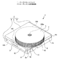
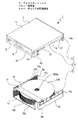
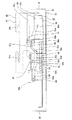
ディスクカートリッジ1はケース体2の内部に所要の各部が配置されて成り、ケース体2は第1のシェル3と第2のシェル4を有している。ケース体2の内部には複数のディスク状記録媒体200、200、・・・が上下方向に等間隔で収納可能とされている。
The
第1のシェル3と第2のシェル4は、例えば、上下方向において結合又は分離可能とされている(図1乃至図3参照)。尚、ケース体2が縦長の状態とされている場合には、第1のシェル3と第2のシェル4は、左右方向において結合又は分離される。
For example, the
第1のシェル3はベース体5とベース体5の後端部に取り付けられた補助ベース6とが上下方向において結合されて成る。
The
ベース体5は上下方向を向くベース面部7とベース面部7の左右両端部からそれぞれ下方へ突出されたサイド面部8、8とベース面部7の後端部から下方へ突出されたリア面部9とを有している。
The base body 5 includes a base surface portion 7 facing in the vertical direction,
ベース面部7の中央部には下方へ突出された丸軸状のセンターピン10が設けられている。
A
ベース面部7の前端寄りの位置には下方へ突出された支持軸11、11が左右に離隔して設けられている。
補助ベース6の左右両端部における下端部にはそれぞれ側方(外方)及び下方に開口された溝状の把持部6a、6aが形成されている。
Groove-shaped
第1のシェル3の左右両側面部における後端寄りの位置には、それぞれスライダー支持部3a、3aが形成されている。
第1のシェル3の支持軸11、11にはそれぞれロックレバー12、12が回動自在に支持されている。
Lock levers 12 and 12 are rotatably supported on the
ロックレバー12の先端部には側方へ突出されたロック用突部12aが設けられている(図4参照)。ロックレバー12、12が支持軸11、11に支持された状態において、ロックレバー12、12は図示しない付勢バネによってロック用突部12a、12aがそれぞれサイド面部8、8に近付く方向へ付勢されている。
A locking
第1のシェル3のスライダー支持部3a、3aにはそれぞれロックスライダー13、13が前後方向へスライド自在に支持されている(図1乃至図4参照)。ロックスライダー13、13はそれぞれ図示しないコイルバネによって前方へ付勢されている。ロックスライダー13、13には前後方向における中間部にそれぞれ内方へ突出されたロック部13a、13aが設けられている(図3及び図4参照)。
第1のシェル3の前端部には開閉パネル14が取り付けられている(図1乃至図4参照)。開閉パネル14には左右に離隔して挿入孔14a、14aが形成されている。開閉パネル14の左右両端部にはそれぞれ外方に開口された挿入用切欠14b、14bが形成されている。
An open /
第2のシェル4は上下方向を向く基面部15と基面部15の左右両端部からそれぞれ上方へ突出された側面部16、16とが一体に形成されて成る。
The
側面部16には、前端部に前方に開口され左右に貫通された第1のロック用凹部16aが形成され、後端寄りの位置に後方及び外方に開口された第2のロック用凹部16bが形成されている。
The
側面部16の内面には保持溝16c、16c、・・・が形成され、保持溝16c、16c、・・・は上下方向において等間隔に離隔して位置されている。
Holding
第2のシェル4の側面部16、16間の後端寄りの位置にはブリッジ部材17が取り付けられている(図2参照)。
A bridge member 17 is attached to a position near the rear end between the
ディスクカートリッジ1には、例えば、ケース体2の後面に情報入力手段として情報入力シート18が貼付されている(図1及び図2参照)。情報入力シート18には所定の情報、例えば、ケース体2の内部に収納されるディスク状記録媒体200、200、・・・間のピッチ及びディスク状記録媒体200、200、・・・の収納枚数に関する情報が入力されている。
For example, an
尚、情報入力手段は情報入力シート18に限られることはなく、例えば、ケース体2に印刷されたバーコード等の印刷情報やケース体2に埋め込まれた記録チップ等の適宜の手段を用いることができる。
The information input means is not limited to the
以上のように構成されたディスクカートリッジ1において、ディスク状記録媒体200、200、・・・がケース体2の内部に保持される(図1及び図2参照)。ディスク状記録媒体200は第1のシェル3と第2のシェル4が分離された状態において、外周部が第2のシェル4の側面部16、16に形成された保持溝16c、16cに前方から挿入されてケース体2の内部に保持される。従って、第2のシェル4の前端に位置する開口はディスク状記録媒体200、200、・・・の第2のシェル4に対する挿入及び取出が行われるディスク挿脱口4aとして形成される。
In the
第1のシェル3と第2のシェル4が結合され第1のシェル3に開閉パネル14が取り付けられてケース体2が構成された状態においては、左右両側部にそれぞれ前後に延びる挿入溝2a、2aが形成される(図1参照)。挿入溝2a、2aは、後端がそれぞれ第1のシェル3のスライダー支持部3a、3aに連続され、前端がそれぞれ開閉パネル14に形成された挿入用切欠14b、14bに連続される。
In the state in which the
[ディスクカートリッジの結合状態]
以下に、ディスクカートリッジ1の結合状態について説明する(図4参照)。
[Disc cartridge connection status]
Hereinafter, the coupled state of the
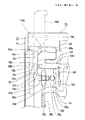
第1のシェル3と第2のシェル4はベース体5のベース面部7と基面部15が上下で対向した状態で結合されている。
The
第1のシェル3と第2のシェル4が結合された状態においては、ロックレバー12、12及びロックスライダー13、13によって第1のシェル3と第2のシェル4がロックされている。
In a state where the
ロックレバー12、12は付勢バネの付勢力によってロック用突部12a、12aが互いに離隔する方向(外方)における回動端に位置され、ロック用突部12a、12aがそれぞれ第2のシェル4の側面部16、16に形成された第1のロック用凹部16a、16aに挿入されて係合されている。
The lock levers 12 and 12 are positioned at rotation ends in a direction (outward) in which the locking
ロックスライダー13、13はコイルバネの付勢力によって前方の移動端に位置され、ロック部13a、13aがそれぞれ第2のシェル4の側面部16、16に形成された第2のロック用凹部16b、16bに挿入されて係合されている。
The
第1のシェル3と第2のシェル4が結合された状態においては、ディスク状記録媒体200、200、・・は中心孔200a、200a、・・・に第1のシェル3に設けられたセンターピン10が挿入される。
In the state where the
[ディスクストレージシステムの全体構成]
次に、ディスクストレージシステム19の全体構成について説明する(図5及び図6参照)。
[Overall configuration of the disk storage system]
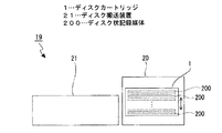
Next, the overall configuration of the
ディスクストレージシステム19はディスクカートリッジ1とディスクカートリッジ1が保持されるディスクチェンジャー20とディスク状記録媒体200、200、・・・を搬送するディスク搬送装置21とを備えている。
The
ディスクチェンジャー20の内部には図示しない昇降機構と昇降機構によって上下方向へ移動される図示しないカートリッジホルダーとが設けられ、カートリッジホルダーにはディスクカートリッジ1が保持される。
Inside the
ディスクカートリッジ1はカートリッジホルダーとともに昇降機構によって上下方向へ移動される(図5参照)。ディスクカートリッジ1とディスク搬送装置21の間ではディスク状記録媒体200が中心軸方向に直交する方向(前後方向)において受け渡される。
The
ディスク状記録媒体200はディスクチェンジャー20に設けられた図示しない取出機構によってディスクカートリッジ1から後方へ取り出され、ディスク搬送装置21によって後方へ向けて搬送され(図6参照)情報信号の記録又は再生が行われる。情報信号の記録又は再生が終了したディスク状記録媒体200は、ディスク搬送装置21によって前方へ向けて搬送され(図6参照)ディスクカートリッジ1に収納される。
The disc-shaped
[ディスク搬送装置の構成]
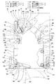
次に、ディスク搬送装置21の具体的な構成について説明する(図7乃至図38参照)。
[Configuration of disk transport device]
Next, a specific configuration of the
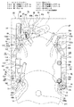
<ベースフレーム>
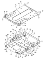
ディスク搬送装置21はベースフレーム22とベースフレーム22を上側から覆う図示しないカバーとを有し、ベースフレーム22は外形が縦長の略矩形状に形成された底面板部23と底面板部23の外周縁からそれぞれ上方へ突出された複数の側面板部24、24、・・・とから成る(図11参照)。
<Base frame>
The
ベースフレーム22の前後方向における略中央部の左右両側には、前後に二つずつの側面板部24、24、・・・が並んで設けられている。前後に並ぶ側面板部24、24間には上方に開口された上下に延びるスリットが形成され、このスリットが案内規制孔24aとして形成されている。
Two
前後方向における略中央部において前後に二つずつ並ぶ側面板部24、24、・・・の外面にはそれぞれ案内規制ピン25、25、・・・が取り付けられている。
Guide guide pins 25, 25,... Are respectively attached to the outer surfaces of the
ベースフレーム22の底面板部23上には図示しない回路基板が配置されている。
A circuit board (not shown) is disposed on the
<ベースプレート>
ベースフレーム22の側面板部24、24にはベースプレート26が取り付けられている(図7参照)。ベースプレート26は外形が縦長の略矩形状に形成されたベース板部27とベース板部27の外周部から下方へ突出された被取付突部28、28、・・・とベース板部27の外周部から上方へ突出された取付突部29、29、・・・とを有している(図12参照)。ベースプレート26は被取付突部28、28、・・・がそれぞれベースフレーム22の側面板部24、24、・・・にネジ止め等によって取り付けられ、ベース板部27が底面板部23の上方に位置されている。
<Base plate>
A
ベース板部27の左右方向における中央部には前後に延びるベースユニット配置孔27aが形成されている。ベース板部27の前端部における左右両端部にはそれぞれアジャスター支持部30、30が設けられている。アジャスター支持部30には上下に貫通された軸取付部30aが形成されている(図13参照)。アジャスター支持部30の軸取付部30aの周囲の部分は上方に開口された凹状部30bとして形成され、凹状部30bには上方へ突出されたバネ係合突部30cが設けられている。
A base
<ルートアジャスター>
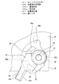
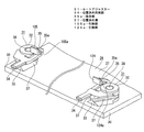
アジャスター支持部30、30にはそれぞれルートアジャスター31、31が回動自在に支持されている(図7参照)。ルートアジャスター31は円筒状の軸挿通部32と軸挿通部32から側方へ突出された位置調整部33と位置調整部33の上端部から突出された位置決め用突部34と位置調整部33の上端部から位置決め用突部34の反対方向へ突出された突状部35と位置調整部33の先端部から下方へ突出されたバネ係合部36とが一体に形成されて成る(図13乃至図16参照)。
<Route adjuster>
位置調整部33は先端に行くに従って幅が小さくなる略三角柱状に形成され、両側面にそれぞれ水平方向に延びる位置決め溝37、37を有している。位置決め溝37の両端部にはそれぞれ先端に行くに従って溝幅が大きくなる案内面37a、37a、・・・が形成されている(図16参照)。
The
位置決め用突部34は位置調整部33の軸挿通部32からの突出方向と同じ方向へ位置調整部33から突出され、左右両端部における上下両端部にそれぞれ外方へ行くに従って上下方向において互いに近付くように傾斜された被案内面34a、34aを有している。
The positioning protrusions 34 protrude from the
突状部35は先端部が上側に屈曲されてV字状に形成された係合部35aとして設けられている。
The projecting
ルートアジャスター31は軸取付部30aに取り付けられた支持軸38を支点としてアジャスター支持部30に回動自在に支持される(図13乃至図15参照)。ルートアジャスター31がアジャスター支持部30に支持された状態においては、アジャスター支持部30の軸取付部30aに戻しバネ38が支持される(図17参照)。戻しバネ38は、例えば、捩じりコイルバネである。
The
ルートアジャスター31が位置決め用突部34が前方側へ移動される方向へ回動されると、戻しバネ39の一端部39aがバネ係合部36に係合されると共に戻しバネ39の他端部39bがバネ係合突部30cに係合され、戻しバネ39によってルートアジャスター31に位置決め用突部34が後方側へ移動される回動方向への付勢力が付与される(図18参照)。逆に、ルートアジャスター31が位置決め用突部34が後方側へ移動される方向へ回動されると、戻しバネ39の他端部39bがバネ係合部36に係合されると共に戻しバネ39の一端部39aがバネ係合突部30cに係合され、戻しバネ39によってルートアジャスター31に位置決め用突部34が前方側へ移動される回動方向への付勢力が付与される(図17参照)。従って、ルートアジャスター31は外力が付与されていない状態において、戻しバネ39によって中立位置に保持される。
When the
左側に位置するルートアジャスター31の中立位置は位置決め用突部34が右方に延びる向きで保持された位置であり、右側に位置するルートアジャスター31の中立位置は位置決め用突部34が左方に延びる向きで保持された位置である。
The neutral position of the
<ベースシャーシ>
ベースプレート26にはベースシャーシ40が取り付けられている(図7参照)。ベースシャーシ40は第1ベース41と第1ベース41の上面における前端側に取り付けられた第2ベース42とから成る。第1ベース41は、例えば、樹脂材料によって形成され、第2ベース42は、例えば、金属材料によって形成されている。
<Base chassis>
A
ベースシャーシ40は外形が縦長の略矩形状に形成され、外周部に被取付用突部40a、40a、・・・が設けられている(図20参照)。ベースシャーシ40は被取付用突部40a、40a、・・・がそれぞれベースプレート26の取付突部29、29、・・・にネジ止め等によって取り付けられ、ベース板部27の上方に位置されている。
The
ベースシャーシ40の左右両端部にはそれぞれ前後に離隔して上方へ突出されたガイド突部40b、40b、・・・が設けられている。
ベースシャーシ40の左端部における前端部には上下に貫通された動作カム部43が形成されている。動作カム部43は、ベースシャーシ40の左前の角部を中心とした略円弧状に形成された第1のカム部43aと、同じく角部を中心とした略円弧状に形成され第1のカム部43aの前端に連続する第2のカム部43bと、第2のカム部43bの前端に連続され左右に短く延びる第3のカム部43cとから成る。第1のカム部43aは第2のカム部43bより幅が広くされ、第1のカム部43aと第2のカム部43bの連続部分には略後方を向く段差縁43dが形成されている。
An
ベースシャーシ40の右端部における前端部にはギヤ移動孔44が形成されている。ギヤ移動孔44はベースシャーシ40の右前の角部を中心とした円弧状に形成されている。
A
ベースシャーシ40の前後方向における略中央部の左右両端部にはそれぞれ第1の軸移動孔45、45と第2の軸移動孔46、46が形成されている。第1の軸移動孔45、45と第2の軸移動孔46、46はそれぞれ中心の位置が異なる内方へ凸の円弧状に形成され、後側に位置する第2の軸移動孔46、46の前端部が第1の軸移動孔45、45の中間部に連通されている。
First and second axial movement holes 45 and 45 and second axial movement holes 46 and 46 are formed at both left and right ends of the substantially central portion of the
ベースシャーシ40には第2の軸移動孔46、46の内側にそれぞれピン移動孔47、47が形成されている。ピン移動孔47、47はそれぞれ外方へ凸の緩やかな円弧状に形成されている。
In the
ベースシャーシ40には左側に位置するピン移動孔47の外側に連続して連結部移動孔48が形成されている。連結部移動孔48はピン移動孔47の中心と同じ中心の円弧状に形成され、ピン移動孔47に連通された状態で形成されている。
In the
ベースシャーシ40には左側に位置するピン移動孔47の内側に、作用軸移動孔49が形成されている。作用軸移動孔49はピン移動孔47の中心と同じ中心の円弧状に形成されている。
In the
ベースシャーシ40の中央部には上方に開口された配置用凹部50が形成されている。配置用凹部50の前後両端部にはそれぞれ上方へ突出された支持ピン50a、50aが設けられている。配置用凹部50の略中央部には円形状のテーブル挿通孔50bが形成されている。
An
ベースシャーシ40の下面における前端側の位置には下方へ突出された摺動突部40c、40cが左右に離隔して設けられている。摺動突部40c、40cはベースシャーシ40の左前の角部を中心とした円弧状に形成され、前端がベースシャーシ40の前端に一致されている。
Sliding
ベースシャーシ40には、左右両端寄りの位置にそれぞれ下面から下方へ突出されたバネ支持軸40d、40dが設けられ、左右両端部にはバネ押さえ部40e、40eが設けられている。バネ押さえ部40e、40eはそれぞれバネ支持軸40d、40dの近傍に位置されている。
The
ベースシャーシ40の左端寄りの位置には上方へ突出されたロック用作用突部40fとロック解除用作用突部40gが左右に離隔して設けられている(図20参照)。ロック用作用突部40fはロック解除用作用突部40gの稍前方に位置されている。
At the position near the left end of the
<駆動モーター及び各ギヤ等>
ベースシャーシ40の左端部における前端部には取付板51がネジ止め等によって取り付けられている(図7参照)。取付板51はモーター取付部51aと基板取付部51bを有している(図22参照)。取付板51には、モーター取付部51aに駆動モーター52が取り付けられ、基板取付部51bにセンサー基板53が取り付けられている。
<Drive motor and gears>
A mounting
駆動モーター52とセンサー基板53は何れも図示しないフレキシブルプリント配線板によってベースフレーム22の底面板部23上に配置された回路基板に接続されている。
Both the
駆動モーター52は出力軸が左右方向に延びる向きでモーター取付部51aに取り付けられ、出力軸にはウォーム54が固定されている。
The
センサー基板53にはセンサー53a、53aが搭載されている(図7及び図8参照)。
ベースシャーシ40には上面側にウォームギヤ55と伝達ギヤ群56がそれぞれ支持されている(図7、図8及び図22参照)。ウォームギヤ55はウォーム54に噛合され、伝達ギヤ群56はウォームギヤ55に噛合されている。
A
ベースシャーシ40の左端寄りの位置には駆動ギヤ57が支持されており、駆動ギヤ57は伝達ギヤ群56の最終段のギヤに噛合されている。従って、駆動モーター52が回転されると、その駆動力が順にウォーム54、ウォームギヤ55及び伝達ギヤ群56を介して駆動ギヤ57に伝達され、駆動ギヤ57が伝達ギヤ群56によって減速されて回転される。
A
ベースシャーシ40の左右方向における中央部の前端部にはギヤ支持プレート58が回動自在に支持されている。ギヤ支持プレート58はギヤ支持部58aとギヤ支持部58aから略後方へ突出された腕部58bと腕部58bの先端部から上方へ突出された摺動ピン58cとから成る。
A
ギヤ支持プレート58には第1の伝達ギヤ59と切換ギヤ60が噛合された状態で支持されている。第1の伝達ギヤ59はウォームギヤ55に噛合されている。
The
ベースシャーシ60の前端部における右端部には第2の伝達ギヤ61と第3の伝達ギヤ62が噛合された状態で支持されている。
A
第2の伝達ギヤ61はギヤ支持プレート58の回動位置によって切換ギヤ60と噛合され又は噛合が解除される。第3の伝達ギヤ62はベースシャーシ60の右前の角部に支持されている。
The
第2の伝達ギヤ61が切換ギヤ60に噛合された状態において、駆動モーター52が回転されると、その駆動力が順にウォーム54、ウォームギヤ55、第1の伝達ギヤ59、切換ギヤ60及び第2の伝達ギヤ61を介して第3の伝達ギヤ62に伝達される。
When the
<プーリーホルダー及びチャッキングプーリー>
ベースシャーシ60の配置用凹部60には第1のプーリーホルダー63と第2のプーリーホルダー64が配置されている(図8及び図9参照)。
<Pulley holder and chucking pulley>
A
第1のプーリーホルダー63は略左方に凸の略半円弧状に形成された保持部63aと保持部63aの後端部から後方へ突出された被支持部63bと保持部63aの前端部から前方へ突出された連結部63cとから成る(図23及び図24参照)。保持部63aの中間部には上方へ突出された被作用ピン63dが設けられ、連結部63cには上方へ突出された連結ピン63eが設けられている。保持部63aは外周部を除き下方へ傾斜するすり鉢状に形成されている。保持部63aの長手方向における中央部の上面には段差部63fが形成されている。
The
第2のプーリーホルダー64は略右方に凸の略半円弧状に形成された保持部64aと保持部64aの前端部から前方へ突出された被支持部64bと被支持部64bから側方へ突出された連結部64cとから成る。連結部64cには緩やかな円弧状に形成された連結孔64dが形成されている。保持部64aは外周部を除き下方へ傾斜するすり鉢状に形成されている。保持部64aの長手方向における中央部の上面には段差部64eが形成されている。
The
第1のプーリーホルダー63は被支持部63bに配置用凹部50に設けられた一方の支持ピン50aが挿入され、配置用凹部50において一方の支持ピン50aを支点として回動可能とされる。
In the
第2のプーリーホルダー64は被支持部64bに配置用凹部50に設けられた他方の支持ピン50aが挿入され、配置用凹部50において他方の支持ピン50aを支点として回動可能とされる。
In the
第1のプーリーホルダー63の連結ピン63eは第2のプーリーホルダー64の連結孔64dに挿入されて摺動自在に係合され、第1のプーリーホルダー63の回動動作に伴って第2のプーリーホルダー64が回動される。第1のプーリーホルダー63と第2のプーリーホルダー64は保持部63aと保持部64bが離接する方向へ連動して回動される。第1のプーリーホルダー63と第2のプーリーホルダー64が支持ピン50a、50aに支持された状態において、一方の支持ピン50aと第1のプーリーホルダー63の間に捩じりコイルバネ65が支持され、第1のプーリーホルダー63と第2のプーリーホルダー64に保持部63aと保持部64bが接近する方向への付勢力が付与される。
The connecting
第1のプーリーホルダー63と第2のプーリーホルダー64によってチャッキングプーリー66が保持される。チャッキングプーリー66は磁性材料によって形成され、外形が円形状の装着部66aと装着部66aから外方に張り出されたフランジ部66bとを有している。
The chucking
チャッキングプーリー66は第1のプーリーホルダー63の保持部63aと第2のプーリーホルダー64の保持部64aとがフランジ部66bの下側に位置されることにより上方に持ち上げられた状態で保持される(図24及び図25参照)。チャッキングプーリー66が保持された状態から第1のプーリーホルダー63と第2のプーリーホルダー64がコイルバネ65の付勢力に反して離隔する方向へ回動され保持部63a、64aが開いてフランジ部66bの外側に位置されると、チャッキングプーリー66に対する第1のプーリーホルダー63と第2のプーリーホルダー64による保持状態が解除され、チャッキングプーリー66が下方へ移動可能な状態とされる(図26参照)。
The chucking
尚、第1のプーリーホルダー63と第2のプーリーホルダー64にはそれぞれ段差部63f、64eが形成されており、第1のプーリーホルダー63と第2のプーリーホルダー64の保持部63a、64aが離隔していくときに、チャッキングプーリー66が下方へ移動されていく過程において水平な状態に対して傾斜したときにフランジ部66bが何れかの段差部63f、64eに係合しチャッキングプーリー66の傾斜した状態での移動が規制される。この傾斜した状態での移動が規制された状態において、引き続き保持部63a、64aが離隔していくと、チャッキングプーリー66はフランジ部66bが両方の段差部63f、64eに係合するまで移動されて水平な状態とされる。従って、さらに保持部63a、64aが離隔していくときには、チャッキングプーリー66が水平な状態で下方へ移動されていくため、チャッキングプーリー66の適正な向きでの移動が行われる。
The
<連動レバー>
ベースシャーシ40の上面における後端寄りの位置には第1の連動レバー67と第2の連動レバー68が連結された状態で移動自在に支持されている(図8乃至図10参照)。
<Interlocking lever>
A
第1の連動レバー67は上下方向を向く板状に形成され略左斜め後方へ凸のくの字状にされている(図27参照)。第1の連動レバー67には、右端寄りの位置に上方へ突出された連結軸67aが設けられ、左端部に略円弧状の係合孔67bが形成され、係合孔67bの右側に下方へ突出されたディスク保持ピン67cが設けられている。第1の連動レバー67には、左右方向における略中央部に円弧状の軸挿通孔67dが形成され、係合孔67bと軸挿通孔67dの間に下方へ突出された支持軸67eが設けられている。
The
第1の連動レバー67は右端部がベースシャーシ40に回動自在に支持されている。
The right end of the first interlocking
第2の連動レバー68は上下方向を向く板状に形成され略右斜め後方へ凸のくの字状にされている。第2の連動レバー68には、左端寄りの位置に円弧状の連結孔68aが形成され、右端部に略円弧状の係合孔68bが形成されている。第2の連動レバー68には、係合孔68bの近傍に下方へ突出されたディスク保持ピン68cが設けられている。
The
第2の連動レバー68は左端部がベースシャーシ40に回動自在に支持されている。
The
第1の連動レバー67の連結軸67aは第2の連動レバー68の連結孔68aに挿入されて摺動自在に係合され、第1の連動レバー67と第2の連動レバー68がそれぞれ右端部と左端部を支点として連動して回動される。第1の連動レバー67と第2の連動レバー68のディスク保持ピン67c、68cはそれぞれベースシャーシ40のピン移動孔47、47に挿通されてベースシャーシ40の下方へ突出される。
The connecting
第1の連動レバー67の支持軸67eはベースシャーシ40の連結部移動孔48に挿入されて下方へ突出される。第1の連動レバー67の支持軸67eにはスタートレバー69が回動自在に支持される(図10及び図27参照)。
The
スタートレバー69はベースシャーシ40の下面側に位置される。スタートレバー69は一方向に長く形成され、一端部に下方へ突出された被押圧軸69aを有している。スタートレバー69は他端部が第1の連動レバー67に対する回動支点とされている。スタートレバー69の回動支点に寄った位置には上方へ突出された作用軸69bが設けられ、作用軸69bはベースシャーシ40の作用軸移動孔49及び第1の連動レバー67の軸挿通孔67dに挿通されて上方へ突出される。
The
スタートレバー69と第1の連動レバー67のディスク保持ピン67cの間にはコイルバネ70が支持され、コイルバネ70によってスタートレバー69に被押圧軸69aが略前方へ移動する回動方向への付勢力が付与される。
A
<カバープレート>
ベースシャーシ40の第1ベース部41の左右方向における中央部にはカバープレート71がネジ止め等によって上方から取り付けられている(図7及び図8参照)。カバープレート71は縦長の略矩形状に形成され、カバープレート71によって第1のプーリーホルダー63と第2のプーリーホルダー64とチャッキングプーリー66と第1の連動レバー67の一部と第2の連動レバー68の一部とが上方から閉塞される。カバープレート71の左右両端部はガイド部71a、71aとして設けられている。
<Cover plate>
A
<同期ギヤ>
カバープレート71の上面側には同期ギヤ72、72が噛合された状態で支持されている。
<Synchronous gear>
Synchronous gears 72 and 72 are supported on the upper surface side of the
<第1のメインスライダー>
ベースシャーシ40の上面における左端部には第1のメインスライダー73が前後方向へ移動自在に支持されている(図7乃至図9参照)。
<First main slider>
A first
第1のメインスライダー73は上下方向を向く板状のスライド部74とスライド部74の左端部における前後両端部からそれぞれ上方へ突出された結合部75、75とを有している(図28及び図29参照)。
The first
スライド部74の左端部における前半部には右方を向く第1のメインラック部74aと第2のメインラック部74bが前後に離隔して設けられ、第1のメインラック部74aと第2のメインラック部74bの間の部分は無ラック部74cとして形成されている。
A first
スライド部74には前後に離隔して上方へ突出された支持ピン74d、74dが設けられている。スライド部74には、右端寄りの位置に右方を向く連結ラック部74eが設けられ、左右両端部にそれぞれ前後に延びる被ガイド部74f、74fが設けられている。スライド部74の右端寄りの位置における後端部には、後方に開口された挿入用切欠74gが形成されている。
The
スライド部74には左端部における後端寄りの位置にカム孔76が形成されている。カム孔76は開口面積の大きな待機部76aと待機部76aの左端部の前端に連続し前後に延びる第1の直線部76bと第1の直線部76bの前端に連続し前方へ行くに従って左方へ変位するように傾斜された傾斜部76cと傾斜部76cの前端に連続し前後に延びる第2の直線部76dとから成る。
A
スライド部74には連結ラック部74eと右側の被ガイド部74fの間にカム支持孔77が形成されている。カム支持孔77は前後に延びる後側部77aと後側部77aの前端に連続し前方へ行くに従って左方へ変位するように傾斜された中間部77bと中間部77bの前端に連続し前後に延びる前側部77cとから成る。
In the
スライド部74の前端寄りの位置には前後に延びるレバー作用孔74hが形成されている。
A
スライド部74にはレバー作用孔74hに配置されるロック用レバー78が取り付けられている。ロック用レバー78は前後に延びる弾性変形部78aと弾性変形部78aの前端部から右方へ突出されたロック部78bとから成り、弾性変形部78aの後端部がスライド部74に取り付けられている。従って、ロック用レバー78は弾性変形部78aが弾性変形されてレバー作用孔74hにおいて動作される。
A locking
第1のメインスライダー73は被ガイド部74f、74fがそれぞれベースシャーシ40の左端部に設けられたガイド突部40b、40bとカバープレート71の左側のガイド部71aに案内されてベースシャーシ40に前後方向へ移動自在に支持される。
In the first
第1のメインスライダー73がベースシャーシ40に支持された状態においては、連結ラック部74eが左側の同期ギヤ72に噛合される(図7参照)。従って、第1のメインスライダー73の前後方向への移動に伴って同期ギヤ72、72が回転される。
In a state where the first
また、第1のメインスライダー73がベースシャーシ40に支持された状態においては、カム支持孔77に第1のプーリーホルダー63に設けられた被作用ピン63dが挿入される。
When the first
<サブスライダー>
第1のメインスライダー73にはサブスライダー79が前後方向へ移動自在に支持されている(図7乃至図9参照)。
<Sub-slider>
A sub-slider 79 is supported on the first
サブスライダー79は上下方向を向く板状に形成され、サブスライダー79の左端部における前半部に右方を向く第1のサブラック部79aと第2のサブラック部79bが前後に離隔して設けられている(図28及び図29参照)。第1のサブラック部79aと第2のサブラック部79bの間の部分は非ラック部79cとして形成されている。
The sub-slider 79 is formed in a plate shape facing in the vertical direction, and a first
サブスライダー79の第1のサブラック部79aと第2のサブラック部79bのピッチはそれぞれ第1のメインラック部74aと第2のメインラック部74bのピッチと同じにされ、非ラック部79cの前後方向における距離は無ラック部74cの前後方向における距離と同じにされている。
The pitches of the first
サブスライダー79には前後に離隔して前後に延びる被支持孔79d、79dが形成されている。サブスライダー79の後端部には右方へ突出された作用突部79eが設けられている。
The sub-slider 79 is formed with supported
サブスライダー79の前後方向における略中央部にはそれぞれ上方へ突出されたバネ支持突部79fとバネ係合突部79gが設けられている。バネ支持突部79fは後側の被支持孔79dの右方に位置され、バネ係合突部79gはバネ支持突部79fと後側の被支持孔79dとの間に位置されている。
A
サブスライダー79には後側の被支持孔79dの後方に上方へ突出されたレバー支持ピン79hが設けられている。サブスライダー79にはバネ支持突部79fの後方に上方へ突出された回動規制突部79iが設けられている。サブスライダー79にはバネ支持突部79fを挟んでバネ係合突部79gの反対側に上方へ突出されたバネ掛け突部79jが設けられている。
The sub-slider 79 is provided with a
サブスライダー79には左端部における後端寄りの位置にカム作用孔80が形成されている。カム作用孔80は開口面積の大きな待機部80aと待機部80aの左端部の前端に連続し前後に延びる後側直線部80bと後側直線部80bの前端に連続し前後に延びる前側直線部80cとから成る。後側直線部80bは横幅が前側直線部80cの横幅より大きくされている。
A
サブスライダー79の前端寄りの位置にはレバー挿入孔81が形成されている。レバー挿入孔81は前後に延びる挿入部81aと左方に開口された凹状のレバー係合部81bとから成り、レバー係合部81bが挿入部81aの後端寄りの部分に連通されている。
A
サブスライダー79のバネ支持突部79fには位置制御バネ82が支持されている。位置制御バネ82は捩じりコイルバネであり、コイル部82aがバネ支持突部79fに支持され、一端部82bがバネ係合突部79gの前側に位置され、他端部82cがバネ係合突部79gの後側に位置されている。
A
位置制御バネ82の一端部82bと他端部82cの間には後側の被支持孔79dに挿入された第1のメインスライダー73の支持ピン74dが位置されている。
Between the one
サブスライダー79のレバー支持ピン79hにはL字状の作動レバー83が回動自在に支持されている。作動レバー83は略前後方向に延びる第1の部分83aと略左右方向に延びる第2の部分83bとから成り、第1の部分83aと第2の部分83bの連続された部分がレバー支持ピン79hに支持されている。
An L-shaped
作動レバー83は第1の部分83aの一部がカム作用孔80の待機部80aの上側に位置される。作動レバー83の第2の部分83bとバネ掛け突部79jの間には引張コイルバネ84が支持されている。従って、作動レバー83は第2の部分83bが略前方へ移動される方向へ付勢され、第2の部分83bが回動規制部83iに接してサブスライダー79に対する回動が規制される。
A part of the
サブスライダー79は被支持孔79d、79dにそれぞれ支持ピン74d、74dが下方から挿入されることにより、第1のメインスライダー73に前後方向へ移動自在に支持される(図29参照)。
The sub-slider 79 is supported by the first
サブスライダー79が第1のメインスライダー73上に支持された状態においては、第1のメインスライダー73に取り付けられたロック用レバー78がレバー挿入孔81に挿入される。
In a state where the
<第2のメインスライダー>
ベースシャーシ40の上面における右端部には第2のメインスライダー85が前後方向へ移動自在に支持されている(図7乃至図9参照)。
<Second main slider>
A second
第2のメインスライダー85は上下方向を向く板状のスライド部86とスライド部86の右端部における前後両端部からそれぞれ上方へ突出された結合部87、87とを有している。
The second
スライド部86には後端寄りの位置にカム孔88が形成されている。カム孔88は開口面積の大きな待機部88aと待機部88aの右端部の前端に連続し前後に延びる第1の直線部88bと第1の直線部88bの前端に連続し前方へ行くに従って右方へ変位するように傾斜された傾斜部88cと傾斜部88cの前端に連続し前後に延びる第2の直線部88dとから成る。
A
スライド部86には、左端寄りの位置に左方を向く連結ラック部86aが設けられ、左右両端部にそれぞれ前後に延びる被ガイド部86b、86bが設けられている。
The
スライド部86には前端側の位置にカム摺動孔89が形成されている。カム摺動孔89は前後に延びる後側摺動部89aと後側摺動部89aの前端に連続し前方へ行くに従って左方へ変位するように傾斜された傾斜摺動部89bと傾斜摺動部89bの前端に連続し前後に延びる前側摺動部89cとから成る。
A
第2のメインスライダー85は被ガイド部86b、86bがそれぞれベースシャーシ40の右端部に設けられたガイド突部40b、40bとカバープレート71の右側のガイド部71aに案内されてベースシャーシ40に前後方向へ移動自在に支持される。第2のメインスライダー85がベースシャーシ40に支持された状態においては、連結ラック部86aが右側の同期ギヤ72に噛合される(図7参照)。従って、第2のメインスライダー85には第1のメインスライダー73の移動力が同期ギヤ72、72を介して伝達され、第1のメインスライダー73と第2のメインスライダー85が同期して前後方向へ移動される。
In the second
<サイドスライダー>
第1のメインスライダー73の結合部75、75と第2のメインスライダー85の結合部87、87にはそれぞれサイドスライダー90、90が結合されている(図7乃至図9参照)。サイドスライダー90は左右方向を向く板状に形成された側面部91と側面部91の上端部に取り付けられた上下方向を向く板状のガイド部92とから成る(図32参照)。
<Side slider>
サイドスライダー90、90は上端部における前後両端部がそれぞれ第1のメインスライダー73の結合部75、75と第2のメインスライダー85の結合部87、87とに結合され、側面部91、91がそれぞれベースシャーシ40の左右両側面の外側に位置される(図33参照)。
The
側面部91には前後に離隔して昇降用カム孔93、93が形成されている(図32及び図33参照)。昇降用カム孔93は前方へ行くに従って上方へ変位する傾斜カム部93aと傾斜カム部93aの前端に連続し前後方向に延びる前側カム部93bと傾斜カム部93aの後端に連続し前後方向に延びる後側カム部93cとから成り、傾斜カム部93aの後端部に上方に開口する保持凹部93dが形成されている。
Elevating cam holes 93 and 93 are formed in the
側面部91には前側の昇降用カム孔93の下側と後側の昇降用カム孔93の上側とにそれぞれ前後に延びる被ガイド孔91a、91aが形成されている。側面部91の上端寄りの位置には前後に延びる保持孔91b、91bが前後に離隔して形成されている。
Guide holes 91 a and 91 a extending in the front-rear direction are formed in the
ガイド部92にはカム摺動孔94が形成されている。カム摺動孔94は後方に開口され、前後に延びる後側摺動部94aと後側摺動部94aの前端に連続し前方へ行くに従って外方(側方)へ変位するように傾斜された傾斜摺動部94bと傾斜摺動部94bの前端に連続し前後に延びる前側摺動部94cとから成る。
A
サイドスライダー90は被ガイド孔91a、91aにそれぞれベースフレーム22の案内規制ピン25、25が挿入されることによりベースフレーム22に対して前後方向へ移動自在に支持される。サイドスライダー90がベースフレーム22に支持された状態において、サブスライダー79の左側の側縁部が保持孔91b、91bに摺動自在に係合され、サブスライダー79の第1のメインスライダー73からの浮き上がりが防止される。
The
<ユニットプレート及びベースユニット等>
サイドスライダー90、90にはユニットプレート95が上下方向へ移動自在に支持されている(図7参照)。
<Unit plate and base unit>
A
ユニットプレート95は上下方向を向くベース面部96とベース面部96の左右両側縁からそれぞれ上方へ突出された第1のサイド面部98、98とベース面部96の左右両側縁からそれぞれ上方へ突出された第2のサイド面部99、99、・・・とを有している(図11及び図12参照)。
The
ベース面部96は縦長の略矩形状に形成され、前後両端部に左右に離隔した状態で上方へ突出されたバネ掛け片96a、96a、・・・を有している。ユニットプレート95のバネ掛け片96a、96a、・・・とベースフレーム22との間にはそれぞれバネ100、100、・・・が支持され、ユニットプレート95が下方へ付勢されている。
The
第1のサイド面部98は第2のサイド面部99より稍内側に位置され、第1のサイド面部98の外面には被案内ピン98a、98aが上下に離隔して設けられている。被案内ピン98a、98aはベースフレーム22の側面板部24、24間に形成された案内規制孔24aに摺動自在に係合され、ユニットプレート95がベースフレーム22によって左右方向への移動が規制される。
The first
第2のサイド面部99、99、・・・はそれぞれ第1のサイド面部98、98を挟んだ前後に位置されている。第2のサイド面部99の外面には被ガイドピン99aが設けられている。被ガイドピン99aはサイドスライダー90の昇降用カム孔93に摺動自在に係合され、ユニットプレート95がサイドスライダー90、90に上下方向へ移動自在に支持される。
The second
ユニットプレート95がサイドスライダー90、90に支持された状態においては、ベース面部96がベースプレート26のベース板部27とベースシャーシ40の間に位置される。
In a state where the
第1のメインスライダー73と第2のメインスライダー85の前後方向への移動に伴ってサイドスライダー90、90が前後方向へ移動されると、被案内ピン98a、98aがベースフレーム22の案内規制孔24aに案内され、被ガイドピン99aがサイドスライダー90の昇降用カム孔93に摺動されてユニットプレート95が上下方向へ移動される。
When the
ベース面部96上には四つのダンパー97、97、・・・が前後左右に離隔して設けられ、ベース面部96にはダンパー97、97、・・・を介して図示しないベースユニットが取り付けられている。ベースユニットはディスク状記録媒体200が装着されるディスクテーブル、ディスクテーブルを回転させるスピンドルモーター、ディスク状記録媒体200の半径方向へ移動される光ピックアップ等を有している。ディスクテーブルはチャッキングプーリー66の真下に位置され、チャッキングプーリー66を吸着するためのマグネットを有している。
Four
ベースユニットはユニットプレート95の移動に伴って上下方向へ移動され、ディスクテーブルがチャッキングプーリー66に離接される。
The base unit is moved in the vertical direction as the
<第1のリンク機構等>
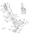
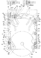
ベースシャーシ40には下面側に第1のリンク機構101が支持されている(図10参照)。第1のリンク機構101は第1の前側リンクアーム102と第1の後側リンクアーム103と第1のレール104とを有している(図34及び図35参照)。
<First link mechanism, etc.>
A
第1の前側リンクアーム102は上下方向を向き一方向に延びる板状に形成され、長手方向における一端部がベースシャーシ40の左下の角部に回動自在に支持されている。第1の前側リンクアーム102の回動支点はベースプレート26の左側のアジャスター支持部30に支持されたルートアジャスター31の回動支点に対して稍後側にずれた位置に形成されている。
The first
第1の前側リンクアーム102の一端部側には側方へ突出された作用片部105が設けられている。作用片部105には一部が下方に切り起こされて形成された引掛部105aが設けられている。
On the one end portion side of the first front
第1の前側リンクアーム102の長手方向における他端部には下面側にスリーブ106が支持されている。第1の前側リンクアーム102の長手方向における中央部には下面側に固定ローラー107が支持されている。固定ローラー107は少なくとも外周部がゴム等の弾性変形可能な密着性の高い材料によって形成されている。
A
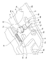
第1の前側リンクアーム102には排出レバー108が回動自在に支持されている。排出レバー108は長手方向において結合された被支持面部109とローラー支持面部111を有している(図34乃至図36参照)。
A
被支持面部109は一方向に長くされた基部109aと基部109aの一端縁から下方へ突出された折曲部109bと折曲部109bの下縁から基部109aと同じ方向に延びる結合部109cとから成る。
The supported
被支持面部109の他端部には上方へ突出されたカム係合部110が設けられている。
A
ローラー支持面部111は基部109aと同じ方向へ延び、一端部が結合部109cに結合されている。
The roller
ローラー支持面部111の他端部の下面側には押圧ローラー112が取り付けられている。押圧ローラー112はローラー部112aとローラー部112aの下端部から外方へ張り出されたフランジ部112bとから成り、ローラー部112aの外周部がゴム等の弾性変形可能な密着性の高い材料によって形成されている。
A
第1の前側リンクアーム102に排出レバー108が支持された状態において、第1の前側リンクアーム102と排出レバー108の間に付勢バネ113が支持される(図36参照)。付勢バネ113は捩じりコイルバネであり、コイル部113aがスリーブ106に支持され、一端部113bが第1の前側リンクアーム102の他端部に係合され、他端部113cが第1の前側リンクアーム102の結合部109cと排出レバー108の一端部との間に挿入されて係合される。従って、付勢バネ113によって排出レバー108に第1の前側リンクアーム102に対して上方から見て反時計回り方向への回動力が付与されると共に上方への移動力が付与される。
In a state where the
第1の前側リンクアーム102がベースシャーシ40に支持された状態において、排出レバー108のカム係合部110がベースシャーシ40の動作カム部43に下方から挿入されて摺動自在に係合される(図10参照)。
In a state where the first
第1の後側リンクアーム103は上下方向を向く一方向に延びる板状に形成され、ベースシャーシ40の前後方向における中央部の左端部に回動自在に支持されている。第1の後側リンクアーム103の回動支点と反対側の端部には上方へ突出された連結軸部103aが設けられている(図34及び図35参照)。第1の後側リンクアーム103がベースシャーシ40に支持された状態において、連結軸部103aがベースシャーシ40の左側の第1の軸移動孔45に下方から挿入され左側の第1の連動レバー67に形成された係合孔67bに挿入されて摺動自在に係合されている。従って、第1の連動レバー67は第1の後側リンクアーム103の動作に連動して動作される。
The first
第1のレール104は第1の前側リンクアーム102と第1の後側リンクアーム103に回動自在に連結されている。第1のレール104は前後に延び、第1の前側リンクアーム102と第1の後側リンクアーム103の回動動作に伴って前後方向に延びる向きで左右方向へ移動される。第1のレール104は前端部と前後方向における略中央部がそれぞれ第1の前側リンクアーム102と第1の後側リンクアーム103に回動自在に連結されている。
The
第1のレール104の前端部における下面側には第1の前側リンクアーム102に支持された固定ローラー107が位置されている。
A fixed
第1のレール104の前端寄りの位置には右方を向く部材取付部104aが設けられている。
A
第1のレール104の前端側には上方へ突出された挿入ピン104bが設けられている(図34及び図35参照)。第1のレール104の後端寄りの位置には上方へ突出された支持ピン104c、104cが前後に離隔して設けられている。第1のレール104の後端部には右方へ突出されたバネ掛け突部104dが設けられている。
An
第1のレール104の部材取付部104aには収納庫114がネジ止め等によって取り付けられている。収納庫114は左方に開口する略コ字状に形成された収納部115と収納部115の下端部の前側に連続して設けられた前側案内部116と収納部115の後側に連続して設けられた後側案内部117とが一体に形成されて成る。
A
収納部115の右端部には右方へ行くに従って互いに離隔する一対の傾斜面が上下に離隔して形成され、この一対の傾斜面がレバー案内面115a、115aとして形成されている。
A pair of inclined surfaces that are spaced apart from each other as they go to the right are formed at the right end of the
前側案内部116の右端部には右方へ行くに従って下方へ変位するように傾斜された前側ディスク案内面116aが形成されている。
A front
後側案内部117の右端部には右方へ行くに従って互いに離隔するように傾斜された後側ディスク案内面117a、117aが上下に離隔して形成されている。
Rear
第1のレール104の支持ピン104c、104cにはリミットレバー118が前後方向へ移動自在に支持されている。リミットレバー118は上下方向を向く被支持板部118aと被支持板部118aの前端部から上方へ突出された被作用軸118bと被支持板部118aの右端部から下方へ突出されたバネ掛け片部118cとから成る。
A
リミットレバー118のバネ掛け片部118cと第1のレール104のバネ掛け突部104dとの間には引張バネ119が支持され、リミットレバー118が第1のレール104に対して後方へ付勢されている。
A
第1のレール104が第1の前側リンクアーム102と第1の後側リンクアーム103に支持された状態において、リミットレバー118の被作用軸118bがベースシャーシ40の左側の第2の軸移動孔46に下方から挿入され第1のメインスライダー73のカム孔76及びサブスライダー79のカム作用孔80に挿入される。
In a state where the
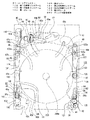
<第2のリンク機構等>
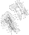
ベースシャーシ40には下面側に第2のリンク機構120が支持されている(図10参照)。第2のリンク機構120は第2の前側リンクアーム121と第2の後側リンクアーム122と第2のレール123とを有している(図38参照)。
<Second link mechanism, etc.>
The
第2の前側リンクアーム121は上下方向を向く一方向に延びる板状に形成され、長手方向における一端部がベースシャーシ40の右下の角部に回動自在に支持されている。第2の前側リンクアーム121の回動支点はベースプレート26の右側のアジャスター支持部30に支持されたルートアジャスター31の回動支点に対して稍後側にずれた位置に形成されている。
The second
第2の前側リンクアーム121の一端部側には側方へ突出された作用片部124が設けられている。作用片部124には一部が下方に切り起こされて形成された引掛部124aが設けられている。
On the one end side of the second front
第2の前側リンクアーム121の一端部にはベースシャーシ40上に支持された第3の伝達ギヤ62が連結され、第3の伝達ギヤ62が第2の前側リンクアーム121に対して回転される。
A
第2の前側リンクアーム121の長手方向における中央部には二段ギヤ125が支持されている。二段ギヤ125の上側のギヤ部125aは第3の伝達ギヤ62に噛合されている。
A two-
第2の前側リンクアーム121の長手方向における他端部には軸部が連結された送りギヤ126、127が上面側と下面側にそれぞれ支持されている。送りギヤ126は二段ギヤ125の下側のギヤ部125bに噛合されている。送りギヤ126、127の軸部における下端部には駆動ローラー128が連結されている。駆動ローラー128は少なくとも外周部がゴム等の弾性変形可能な密着性の高い材料によって形成されている。
Feed gears 126 and 127 having shaft portions connected to the other end portion in the longitudinal direction of the second front
上記したように、第2の伝達ギヤ61が切換ギヤ60に噛合された状態において、駆動モーター52が回転されると、その駆動力が順にウォーム54、ウォームギヤ55、第1の伝達ギヤ59、切換ギヤ60及び第2の伝達ギヤ61を介して第3の伝達ギヤ62に伝達される。第3の伝達ギヤ62に伝達された駆動力は、順に、二段ギヤ125、送りギヤ126及び送りギヤ127に伝達されて駆動ローラー128が回転される。
As described above, when the
第2の前側リンクアーム121がベースシャーシ40に支持された状態において、二段ギヤ125の上側のギヤ部125aがベースシャーシ40のギヤ移動孔44に下方から挿入される。
In a state where the second
第2の後側リンクアーム122は上下方向を向く一方向に延びる板状に形成され、ベースシャーシ40の前後方向における中央部の右端部に回動自在に支持されている。第2の後側リンクアーム122の回動支点と反対側の端部には上方へ突出された連結軸部122aが設けられている。リンクアーム122がベースシャーシ40に支持された状態において、連結軸部122aがベースシャーシ40の右側の第1の軸移動孔45に下方から挿入され右側の第2の連動レバー68に形成された係合孔68bに挿入されて摺動自在に係合されている。従って、第2の連動レバー68は第2の後側リンクアーム122の動作に連動して動作される。
The second
第2のレール123は第2の前側リンクアーム121と第2の後側リンクアーム122に回動自在に連結されている。第2のレール123は前後に延び、第2の前側リンクアーム121と第2の後側リンクアーム122の回動動作に伴って前後方向に延びる向きで左右方向へ移動される。従って、第1のレール104と第2のレール123は常に平行な状態で左右方向へ移動される。
The
第2のレール123は前後方向における長さが第1のレール104より短くされ、前端部と後端寄りの部分がそれぞれ第2の前側リンクアーム121と第2の後側リンクアーム122に回動自在に連結されている。
The length in the front-rear direction of the
第2のレール123の後端部には上方へ突出された被作用軸123aが設けられている。
A rearward end portion of the
第2のレール123の前端側には上方へ突出された挿入ピン123bが設けられている。
An
第2のレール123の前半部には順に噛合された送り平ギヤ129、129、・・・が支持されている。最も前側に位置された送り平ギヤ129は送りギヤ126に噛合されている。最も後側に位置する送り平ギヤ129には同軸上に回転ローラー130が連結されている。
The front
従って、送りギヤ126に伝達された駆動モーター52の駆動力は、順に送り平ギヤ129、129、・・・を介して回転ローラー130に伝達されて回転ローラー130が回転される。回転ローラー130は駆動ローラー128と同期して同じ方向へ回転される。
Therefore, the driving force of the
送りギヤ126と平ギヤ129、129、・・・はギヤカバー131によって下面側から覆われている。
The
第1のリンク機構101の第1のレール104と第2のリンク機構120の第2のレール123とはそれぞれバネ部材132、132によって左右方向において互いに接近する方向へ付勢されている(図21参照)。
The
バネ部材132、132はコイルバネであり、コイル部132a、132aがそれぞれベースシャーシ40のバネ支持軸40d、40dに支持され、一端部132b、132bがそれぞれベースシャーシ40のバネ押さえ部40e、40eに係合され、他端部132c、132cがそれぞれ第1のレール104と第2のレール123に係合されている。
The
第2のレール123が第2の前側リンクアーム121と第2の後側リンクアーム122に支持された状態において、第2のレール123の被作用軸123aがベースシャーシ40の右側の第2の軸移動孔46に下方から挿入され第2のメインスライダー85のカム孔88に挿入される。
In a state where the
また、上記したように、第1の連動レバー67と第2の連動レバー68は連結軸67aが連結孔68aに摺動自在に係合され、第1の後側リンクアーム103は連結軸部103aが第1の連動レバー67の係合孔67bに摺動自在に係合され、第2の後側リンクアーム122は連結軸部122aが第2の連動レバー68の係合孔68bに摺動自在に係合されている。
Further, as described above, the first interlocking
従って、第1の前側リンクアーム102及び第1の後側リンクアーム103に支持された第1のレール104と第2の前側リンクアーム121及び第2の後側リンクアーム122に支持された第2のレール123とは第1の連動レバー67及び第2の連動レバー68を介して連結されており、互いに離接する方向へ左右方向において平行移動される。
Accordingly, the
[ディスク搬送装置の動作]
以下に、ディスク搬送装置21のディスク状記録媒体200に対する搬送動作について説明する(図39乃至図76参照)。
[Operation of disk transport device]
Hereinafter, the transport operation of the
ディスク搬送装置21は、各部がディスク状記録媒体200をローディングする前の初期状態から動作を開始し、ディスクカートリッジ1から取り出されたディスク状記録媒体200をローディング動作によりチャッキング位置まで引込方向(後方)へ搬送し、チャッキング位置においてディスク状記録媒体200をチャッキングしてディスク状記録媒体200に記録された情報信号の記録又は再生を行う。ディスク搬送装置21は、ディスク状記録媒体200に対する情報信号の記録又は再生が終了すると、ディスク状記録媒体200に対するチャッキングを解除し、チャッキング位置からディスク状記録媒体200をイジェクト動作により排出方向(前方)へ搬送してディスクカートリッジ1に収納し、ディスクカートリッジ1へのディスク状記録媒体200の収納後に初期状態に戻る。
The
ローディング動作及びイジェクト動作においては、ディスク状記録媒体200が固定ローラー107、押圧ローラー112、駆動ローラー128及び回転ローラー130によって搬送され、これらの固定ローラー107、押圧ローラー112、駆動ローラー128及び回転ローラー130が搬送ローラーとして機能する。
In the loading operation and the ejecting operation, the disc-shaped
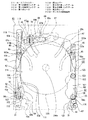
<初期状態>
先ず、各部の初期状態について説明する(図39乃至図41参照)。
<Initial state>
First, the initial state of each part will be described (see FIGS. 39 to 41).
初期状態においてルートアジャスター31、31はそれぞれ戻しバネ39、39によって中立位置に保持されている。
In the initial state, the
左側に位置するルートアジャスター31の中立位置は位置決め用突部34が右方に延びる向きで保持された位置であり、右側に位置するルートアジャスター31の中立位置は位置決め用突部34が左方に延びる向きで保持された位置である。
The neutral position of the
初期状態においては、駆動モーター52は回転されておらず、駆動ギヤ57と駆動ローラー128は何れも回転されていない。
In the initial state, the
初期状態においては、第1のメインスライダー73は第1のメインラック部74a及び第2のメインラック部74bが何れも駆動ギヤ57に噛合されず無ラック部74cが駆動ギヤ57に対向して位置された非噛合位置にある。
In the initial state, the first
初期状態においては、サブスライダー79は非ラック部79cが無ラック部74cの真上に位置され、非ラック部79cが駆動ギヤ57に対向して位置された非噛合位置にあり、第1のサブラック部79a及び第2のサブラック部79bとも駆動ギヤ57に噛合されていない。このとき第1のメインスライダー73の支持ピン74d、74dがそれぞれサブスライダー79の被支持孔79d、79dの前後方向における中央部に位置されている。
In the initial state, the sub-slider 79 is in the non-meshing position in which the
第1のメインスライダー73に取り付けられたロック用レバー78はロック部78bがサブスライダー79のレバー挿入孔81における挿入部81aの開口縁に接した状態とされ、サブスライダー79は第1のメインスライダー73に対してロックされていない。
The locking
第2のメインスライダー85は第1のメインスライダー73の位置に応じて移動範囲の中央に保持されている。
The second
第1のメインスライダー73が初期状態にあるときには、第1のレール104に支持されたリミットレバー118の被作用軸118bが第1のメインスライダー73のカム孔76における待機部76aの前側開口縁に接した状態とされている。また、このとき、第2のレール123の被作用軸123aが第2のメインスライダー85のカム孔88における待機部88aの前側開口縁に接した状態とされている。
When the first
初期状態においては、第1の前側リンクアーム102、第1の後側リンクアーム103、第2の前側リンクアーム121及び第2の後側リンクアーム122とも内側に傾斜した状態とされており、排出レバー108も内側に傾斜した状態とされている。従って、排出レバー108のローラー支持面部111及び押圧ローラー112は収納庫114から右方へ引き出された状態とされている。
In the initial state, the first front
このとき第1の前側リンクアーム102に支持された固定ローラー107と第2の前側リンクアーム121に支持された駆動ローラー128との距離はディスク状記録媒体200の直径より小さくされている。
At this time, the distance between the fixed
第1のメインスライダー73が初期状態にあるときには、第1のプーリーホルダー63の被作用ピン63dが第1のメインスライダー73のカム支持孔77における後側部77aに係合されている。従って、第1のプーリーホルダー63と第2のプーリーホルダー64は保持部63a、64aがチャッキングプーリー66の下側に位置された保持位置にあり、チャッキングプーリー66が保持部63a、64aによって上方に持ち上げられた状態で保持されている。
When the first
第2のメインスライダー85が初期状態にあるときには、ギヤ支持プレート58の摺動ピン58cが第2のメインスライダー85のカム摺動孔89における後側摺動部89aに係合されている。従って、ギヤ支持プレート58は切換ギヤ60が第2の伝達ギヤ61に近付く方向へ回動されており、切換ギヤ60が第2の伝達ギヤ61に噛合されて駆動モーター52の駆動力が駆動ローラー128に伝達可能な状態とされている。
When the second
サブスライダー79が初期状態にあるときには、引張コイルバネ84によって前方へ付勢された作動レバー83の第2の部分83bが回動規制突部79iに押し付けられ平面で見て時計回り方向の回動端に保持されている。このとき第1の連動レバー67に回動自在に支持されたスタートレバー69の作用軸69bがサブスライダー79の作用突部79eより前方に位置されている。
When the sub-slider 79 is in the initial state, the
サイドスライダー90、90はそれぞれ第1のメインスライダー73と第2のメインスライダー85に結合されており、第1のメインスライダー73と第2のメインスライダー85の移動位置に応じた位置に保持されている。このときバネ100、100、・・・によって下方へ付勢されたユニットプレート95は第2のサイド面部99、99の被ガイドピン99a、99a、・・・がそれぞれ昇降用カム孔93、93、・・・の保持凹部93d、93d、・・・に押し付けられた状態で係合されている。従って、ユニットプレート95及びユニットプレート95に配置されたベースユニットは下方の移動端に保持されている。
The
ユニットプレート95の被ガイドピン99a、99a、・・・がバネ100、100、・・・の付勢力によってそれぞれ昇降用カム孔93、93、・・・の保持凹部93d、93d、・・・に押し付けられることにより、ユニットプレート95及びベースユニットの上下方向における位置精度の向上が図られている。
The guided pins 99a, 99a,... Of the
<ローディング動作>
ディスクチェンジャー20に設けられた取出機構によってディスクカートリッジ1からディスク状記録媒体200が後方(引込方向)へ取り出されると、ディスク搬送装置21によって以下のようなローディング動作が行われる(図42乃至図54参照)。
<Loading operation>
When the disc-shaped
ディスクカートリッジ1からディスク状記録媒体200が後方へ取り出されると、ディスク状記録媒体200の外周面がルートアジャスター31、31に接してルートアジャスター31、31がディスク状記録媒体200によって後方へ押圧される(図42参照)。ルートアジャスター31、31には位置決め溝37、37が形成されており、ディスク状記録媒体200の外周部が案内面37a、37a、・・・に案内されて位置決め溝37、37に挿入される。
When the disc-shaped
従って、案内面37a、37a、・・・によってディスク状記録媒体200の外周部が確実に位置決め溝37、37に挿入され、ディスク状記録媒体200の上下方向における位置精度の向上が図られる。
Therefore, the outer peripheral portion of the disc-shaped
ディスク状記録媒体200によって押圧されたルートアジャスター31、31はディスク状記録媒体200を位置決めした状態でそれぞれ戻しバネ39、39の付勢力に反して回動されていく。
The
ディスク状記録媒体200は外周面が駆動ローラー128と固定ローラー107に接触される。このときディスク状記録媒体200の挿入に基づくセンサー基板53に搭載されたセンサー53aの検出動作によって駆動モーター52が回転される。駆動モーター52が回転されると、その駆動力が順にウォーム54、ウォームギヤ55及び伝達ギヤ群56を介して駆動ギヤ57に伝達され、駆動ギヤ57が伝達ギヤ群56によって減速されて回転される。また、駆動モーター52の駆動力は順にウォーム54、ウォームギヤ55、第1の伝達ギヤ59、切換ギヤ60、第2の伝達ギヤ61、、第3の伝達ギヤ62、二段ギヤ125、送りギヤ126及び送りギヤ127に伝達されて駆動ローラー128が回転される。このとき駆動モーター52の駆動力は送りギヤ126から平ギヤ129、129、・・・を介して回転ローラー130にも伝達され、回転ローラー130が駆動ローラー128と同期して同じ方向へ回転される。
The disc-shaped
駆動ギヤ57が回転されても第1のメインスライダー73とサブスライダー79はともに非噛合位置にあるため、第1のメインスライダー73、サブスライダー79及び第2のメインスライダー85は移動されない。
Even when the
駆動ローラー128が回転されると、駆動ローラー128と固定ローラー107によってディスク状記録媒体200が後方へ搬送されていく(図43参照)。
When the driving
ディスク状記録媒体200が後方へ搬送されていくときには、さらにルートアジャスター31、31がディスク状記録媒体200を位置決めした状態でそれぞれ戻しバネ39、39の付勢力に反して回動されていく。
When the disc-shaped
ディスク状記録媒体200が後方へ搬送されていくと、第1のレール104と第2のレール123が互いに離隔する方向へ平行移動され第1の前側リンクアーム102、第1の後側リンクアーム103、第2の前側リンクアーム121及び第2の後側リンクアーム122とも外側へ回動されていく。このとき排出レバー108も第1の前側リンクアーム102の回動動作に伴って外側へ回動されていく。
When the disc-shaped
また、第1の前側リンクアーム102と第2の前側リンクアーム121の回動動作に伴って第1の連動レバー67と第2の連動レバー68がそれぞれ所定の方向へ回動される。
Further, the first interlocking
第1のレール104が移動されていくときには、リミットレバー118の被作用軸118bがベースシャーシ40の左側の第2の軸移動孔46を移動されていく。
When the
排出レバー108が第1の前側リンクアーム102の回動動作に伴って回動されていくときには、排出レバー108のカム係合部110がベースシャーシ40の動作カム部43に摺動されて移動されていく。
When the
第1の後側リンクアーム103が回動されていくときには、連結軸部103aがベースシャーシ40の左側の第1の軸移動孔45及び第1の連動レバー67に形成された係合孔67bを移動されていく。
When the first
第2のレール123が移動されていくときには、被作用軸123aがベースシャーシ40の右側の第2の軸移動孔46を移動されていく。
When the
第2の前側リンクアーム121が回動されていくときには、リンクアーム121に支持された二段ギヤ125の上側のギヤ部125aがベースシャーシ40のギヤ移動孔44を移動されていく。
When the second
第2の後側リンクアーム122が回動されていくときには、連結軸部122aがベースシャーシ40の右側の第1の軸移動孔45及び第2の連動レバー68に形成された係合孔68bを移動されていく。
When the second
第1の連動レバー67と第2の連動レバー68が回動されていくときには、ディスク保持ピン67c、68cがそれぞれベースシャーシ40のピン移動孔47、47を移動されていく。このとき第1の連動レバー67の支持軸67eはベースシャーシ40の連結部移動孔48を移動され、スタートレバー69の作用軸69bはベースシャーシ40の作用軸移動孔49及び第1の連動レバー67の軸挿通孔67dを移動されていく。
When the first interlocking
駆動ローラー128と固定ローラー107によってさらにディスク状記録媒体200が後方へ搬送されていく。
The disc-shaped
ディスク状記録媒体200がさらに後方へ搬送されていくときには、さらにルートアジャスター31、31がディスク状記録媒体200を位置決めした状態でそれぞれ戻しバネ39、39の付勢力に反して回動されていく。
When the disc-shaped
ディスク状記録媒体200がさらに後方へ搬送されていくときには、第1のレール104と第2のレール123が互いに離隔する方向へさらに平行移動されるため、リミットレバー118の被作用軸118bによってサブスライダー79に支持されている作動レバー83の第1の部分83aが左方へ押圧される(図44参照)。従って、作動レバー83は引張コイルバネ84の付勢力に反して平面で見て反時計回り方向へ回動される。第1のレール104と第2のレール123は互いに離隔する方向へ引き続き平行移動されるため、リミットレバー118の被作用軸118bが作動レバー83の第1の部分83aを上側から乗り越えるようにして左方へ移動され、作動レバー83が引張コイルバネ84の付勢力によって平面で見て時計回り方向へ回動されて第2の部分83bが回動規制突部79iに後方から接する元の位置に戻る。リミットレバー118の被作用軸118bは第1のレール104の移動に伴ってさらに左方へ移動され第1のメインスライダー73のカム孔76における待機部76aの左端寄りに位置される。
When the disc-shaped
このとき第1の前側リンクアーム102、第1の後側リンクアーム103、第2の前側リンクアーム121及び第2の後側リンクアーム122ともさらに外側へ回動されていく(図45参照)。第1のレール104と第2のレール123が互いに離隔する方向へさらに平行移動され、駆動ローラー128と固定ローラー107を結ぶ線上にディスク状記録媒体200の中心が位置されたときには、第1のレール104と第2のレール123が大きく離隔し第1の前側リンクアーム102、第1の後側リンクアーム103、第2の前側リンクアーム121及び第2の後側リンクアーム122が略前後に延びる状態とされる。
At this time, the first
上記したように、駆動ローラー128と固定ローラー107によってさらにディスク状記録媒体200が後方へ搬送され第1の前側リンクアーム102が略前後に延びる状態とされたときには、排出レバー108も第1の前側リンクアーム102に伴ってさらに回動されローラー支持面部111及び押圧ローラー112が収納庫114の収納部115に収納される。
As described above, when the disc-shaped
さらに駆動ローラー128と固定ローラー107によってディスク状記録媒体200が後方へ搬送されていくと、ディスク状記録媒体200の外周面が駆動ローラー128、固定ローラー107、押圧ローラー112及び回転ローラー130に接した状態とされる(図46参照)。
When the disc-shaped
このときディスク状記録媒体200の外周部が収納庫114の前側案内部116に形成された前側ディスク案内面116aに案内されて後方へ搬送されていく。
At this time, the outer peripheral portion of the disc-shaped
さらにディスク状記録媒体200が後方へ搬送されていくときには、ルートアジャスター31、31とディスク状記録媒体200の接触が解除され、ルートアジャスター31、31がそれぞれ戻しバネ39、39の付勢力によって中立位置まで回動される。
When the disc-shaped
さらにディスク状記録媒体200が後方へ搬送されていくときには、第1のレール104と第2のレール123が互いに接近する方向へ平行移動され第1の前側リンクアーム102、第1の後側リンクアーム103、第2の前側リンクアーム121及び第2の後側リンクアーム122とも内側へ回動される。
When the disc-shaped
続いて、ディスク状記録媒体200は回転ローラー130と押圧ローラー112によって後方へ搬送されていき、駆動ローラー128と固定ローラー107はディスク状記録媒体200の外周面から離隔される(図47参照)。
Subsequently, the disc-shaped
ディスク状記録媒体200がさらに後方へ搬送されていくときには、第1のレール104と第2のレール123が互いに離隔する方向へ再び平行移動され第1の前側リンクアーム102、第1の後側リンクアーム103、第2の前側リンクアーム121及び第2の後側リンクアーム122とも再び外側へ回動されていく。第1のレール104と第2のレール123が互いに離隔する方向へ平行移動され、回転ローラー130と押圧ローラー112を結ぶ線上にディスク状記録媒体200の中心が位置されたときには、第1のレール104と第2のレール123が再び大きく離隔し第1の前側リンクアーム102、第1の後側リンクアーム103、第2の前側リンクアーム121及び第2の後側リンクアーム122が再び略前後に延びる状態とされる。
When the disc-shaped
上記のようにディスク状記録媒体200が回転ローラー130と押圧ローラー112によって後方へ搬送されていくときには、ディスク状記録媒体200の外周部が収納庫114の前側案内部116の前側ディスク案内面116aと後側案内部117の後側ディスク案内面117a、117aとに案内されて後方へ搬送されていく。
As described above, when the disc-shaped
引き続き駆動ローラー128と固定ローラー107によってディスク状記録媒体200はチャッキング位置まで後方へ搬送されていく(図48参照)。
Subsequently, the disc-shaped
ディスク状記録媒体200がチャッキング位置、即ち、ディスク状記録媒体200の中心孔200aがベースユニットのディスクテーブルの真上に存在する位置まで搬送されると、ディスク状記録媒体200の外周面が押圧ローラー112、回転ローラー130、第1の連動レバー67のディスク保持ピン67c及び第2の連動レバー68のディスク保持ピン68cに接した状態とされ、ディスク状記録媒体200が4点で保持されてディスク状記録媒体200の移動がチャッキング位置において停止される。
When the disc-shaped
ディスク状記録媒体200がチャッキング位置まで搬送されたときには、リミットレバー118の被作用軸118bが第1のメインスライダー73のカム孔76における待機部76aの左端寄りの位置まで移動され、第2のレール123の被作用軸123aが第2のメインスライダー85のカム孔88における待機部88aの右端寄りの位置まで移動されている。
When the disc-shaped
ディスク状記録媒体200がチャッキング位置まで搬送されたときには、ディスク状記録媒体200の外周面によって第1の連動レバー67に回動自在に支持されたスタートレバー69の被押圧軸69aが後方へ押圧される。被押圧軸69aがディスク状記録媒体200によって後方へ押圧されると、スタートレバー69がコイルバネ70の付勢力に反して回動され、作用軸69bによってサブスライダー79の作用突部79eが後方へ押圧される(図49参照)。
When the disc-shaped
スタートレバー69が回動されて作用軸69bによって作用突部79eが後方へ押圧されると、サブスライダー79が非噛合位置から第1のメインスライダー73に対して後方へ移動され駆動モーター52の駆動力によって回転されている駆動ギヤ57に第1のサブラック部79aが噛合される。このときサブスライダー79が非噛合位置から第1のメインスライダー73に対して後方へ移動されることにより、位置制御バネ82の一端部82bが相対的に第1のメインスライダー73の支持ピン74dに前方へ押圧され、位置制御バネ82によってサブスライダー79に前方への移動力が付与される。
When the
駆動ギヤ57に第1のサブラック部79aが噛合されると、サブスライダー79が駆動モーター52の駆動力によって後方へ移動されていく。サブスライダー79が後方へ移動されると被支持孔79d、79dの前側開口縁がそれぞれ第1のメインスライダー73の支持ピン74d、74dに接する。サブスライダー79は後方へ移動されるため、作用突部79eが作用軸69bから後方へ離隔されていく。
When the first
支持ピン74d、74dはサブスライダー79の第1のメインスライダー73に対する移動を規制する移動規制部として機能し、被支持孔79d、79dは移動規制部として機能する支持ピン74d、74dによってサブスライダー79の第1のメインスライダー73に対する移動が規制される被規制部として機能する。
The support pins 74d and 74d function as a movement restricting portion that restricts the movement of the
被支持孔79d、79dの前側開口縁がそれぞれ第1のメインスライダー73の支持ピン74d、74dに接した状態で引き続きサブスライダー79が後方へ移動されていくと、被支持孔79d、79dの前側開口縁によってそれぞれ支持ピン74d、74dが後方へ押圧され、第1のメインスライダー73とサブスライダー79が一体になって後方へ移動されていく(図50参照)。従って、第1のメインスライダー73の第1のメインラック部74aが駆動ギヤ57に噛合され、駆動ギヤ57には第1のメインラック部74aとサブスライダー79の第1のサブラック部79aとがともに噛合される。
When the sub-slider 79 is continuously moved rearward with the front opening edges of the supported
第1のメインスライダー73とサブスライダー79が一体になって後方へ移動されていくと、リミットレバー118の被作用軸118bが第1のメインスライダー73のカム孔76における待機部76aから第1の直線部76bまで移動され、第2のレール123の被作用軸123aが第2のメインスライダー85のカム孔88における待機部88aから第1の直線部88bまで移動される。
When the first
このとき第2のメインスライダー85の後方への移動により、ギヤ支持プレート58の摺動ピン58cが第2のメインスライダー85のカム摺動孔89の後側摺動部89aから傾斜摺動部89bを経て前側摺動部89cまで移動される。従って、ギヤ支持プレート58が平面で見て反時計回り方向へ回動され、切換ギヤ60が移動されて切替ギヤ60と第2の伝達ギヤ61との噛合が解除され、駆動ローラー128と回転ローラー130の回転が停止される。
At this time, due to the rearward movement of the second
第1のメインスライダー73及び第2のメインスライダー85が上記のように後方へスライドされるときにはサイドスライダー90、90が一体になって後方へ移動される(図51参照)。
When the first
サイドスライダー90、90が後方へ移動されると、バネ100、100、・・・によって下方へ付勢されたユニットプレート95の被ガイドピン99a、99a、・・・がそれぞれ昇降用カム孔93、93、・・・の保持凹部93d、93d、・・・から傾斜カム部93a、93a、・・・に移動される。従って、ユニットプレート95及びユニットプレート95に配置されたベースユニットが上方へ移動されディスクテーブルがチャッキングプーリー66に接近されていく。
When the
さらに駆動ギヤ57の回転により第1のメインスライダー73とサブスライダー79が一体になって後方へ移動されていく(図52参照)。
Further, the first
さらに駆動ギヤ57の回転により第1のメインスライダー73とサブスライダー79が一体になって後方へ移動されていくことにより、リミットレバー118の被作用軸118bが第1のメインスライダー73のカム孔76における第1の直線部76bから傾斜部76cを経て第2の直線部76dまで移動される。同時に、第2のレール123の被作用軸123aが第2のメインスライダー85のカム孔88における第1の直線部88bから傾斜部88cを経て第2の直線部88dまで移動される。
Further, when the
従って、第1のレール104と第2のレール123が互いに離隔する方向へ移動され、押圧ローラー112と回転ローラー130がディスク状記録媒体200の外周部から離隔される(図53参照)。同時に、第1の後側リンクアーム103と第2の後側リンクアーム122の回動動作に伴い第1の連動レバー67と第2の連動レバー68が回動され、ディスク保持ピン67c、68cがディスク状記録媒体200の外周面から離隔される。
Accordingly, the
第1のレール104と第2のレール123は最も離隔する位置まで移動される。
The
第1のレール104と第2のレール123が最も離隔する位置まで移動されるときには、同時に、第1のメインスライダー73の後方への移動により第1のプーリーホルダー63の被作用ピン63dが第1のメインスライダー73のカム支持孔77における後側部77aから中間部77bを経て前側部77cまで移動される。従って、チャッキングプーリー66を保持する保持位置から第1のプーリーホルダー63と第2のプーリーホルダー64がコイルバネ65の付勢力に反して離隔する方向へ回動され、チャッキングプーリー66に対する第1のプーリーホルダー63と第2のプーリーホルダー64の保持状態が解除され、チャッキングプーリー66が下方へ移動可能な状態とされる。
When the
また、このとき同時に、第1のメインスライダー73と第2のメインスライダー85の後方への移動に伴ってサイドスライダー90、90が後方へ移動され、ユニットプレート95の被ガイドピン99a、99a、・・・がそれぞれ昇降用カム孔93、93、・・・の傾斜カム部93a、93a、・・・から前側カム部93b、93b、・・・まで移動される(図54参照)。従って、ユニットプレート95及びユニットプレート95に配置されたベースユニットが上方の移動端まで移動される。ベースユニットが上方の移動端まで移動された状態においては、ベースユニットの一部がベースプレート26のベース板部27に形成されたベースユニット配置孔27aに配置される。
At the same time, as the first
ベースユニットが上方の移動端まで移動されると、ディスクテーブルにチャッキングプーリー66が吸着されディスク状記録媒体200がディスクテーブルとチャッキングプーリー66によって挟持されてチャッキングされ、ディスク状記録媒体200のローディングが完了する。
When the base unit is moved to the upper moving end, the chucking
サイドスライダー90、90が後方へ移動されるときには、上記したように、第1のレール104と第2のレール123が最も離隔する位置へ向けて移動され、第1のレール104の挿入ピン104bと第2のレール123の挿入ピン123bとがそれぞれサイドスライダー90、90のガイド部92、92に形成されたカム摺動孔94、94に挿入される。
When the
挿入ピン104b、123bはそれぞれカム摺動孔94、94の後側摺動部94a、94aと傾斜摺動部94b、94bを経て前側摺動部94c、94cまで挿入される。従って、第1のレール104と第2のレール123は最も離隔する位置において保持される。
The insertion pins 104b and 123b are inserted to the front sliding
第1のメインスライダー73、サブスライダー79及び第2のメインスライダー85は後方の移動端まで移動されて停止される。第1のメインスライダー73、サブスライダー79及び第2のメインスライダー85が後方の移動端まで移動されると、駆動モーター52の駆動が停止されて駆動ギヤ57の回転が停止される。
The first
ディスク状記録媒体200がディスクテーブルとチャッキングプーリー66によってチャッキングされると、ディスクテーブルが回転されると共に光ピックアップの駆動が開始されディスク状記録媒体200に対する情報信号の記録又は再生が行われる。
When the disk-shaped
情報信号の記録又は再生が終了すると、ディスクテーブルの回転が停止されると共に光ピックアップの駆動が終了する。 When the recording or reproduction of the information signal is finished, the rotation of the disk table is stopped and the driving of the optical pickup is finished.
<イジェクト動作>
ディスク状記録媒体200に対する情報信号の記録又は再生が終了すると、ディスク搬送装置21によって以下のようなイジェクト動作が行われる(図55乃至図72参照)。
<Eject operation>
When the recording or reproducing of the information signal with respect to the disc-shaped
イジェクト動作は駆動モーター52がローディング動作における回転方向と反対方向へ回転されることにより開始される。
The ejection operation is started when the
駆動モーター52が回転されると、上記したローディング動作における各動作と逆の動作によりディスク状記録媒体200がディスクカートリッジ1へ向けて前方(排出方向)へ搬送され、ディスク状記録媒体200がディスク搬送装置21から排出されていく(図55参照)。このとき第1のメインスライダー73及びサブスライダー79は駆動モーター52の駆動力によって一体になって前方へ移動される。
When the
第1のメインスライダー73及び第2のメインスライダー85が前方へ移動されるため、リミットレバー118の被作用軸118bが第1のメインスライダー73のカム孔76における第2の直線部76dから傾斜部76c及び第1の直線部76bを経て待機部76aの左端寄りの位置まで移動される。また、第2のレール123の被作用軸123aが第2のメインスライダー85のカム孔88における第2の直線部88dから傾斜部88c及び第1の直線部88bを経て待機部88aまで移動される。このときギヤ支持プレート58の摺動ピン58cが第2のメインスライダー85のカム摺動孔89の前側摺動部89cから傾斜摺動部89bを経て後側摺動部89aまで移動され、切替ギヤ60と第2の伝達ギヤ61が再び噛合される。
Since the first
また、第1のメインスライダー73の前方への移動により第1のプーリーホルダー63の被作用ピン63dが第1のメインスライダー73のカム支持孔77における前側部77cから中間部77bを経て後側部77aまで移動され、チャッキングプーリー66が第1のプーリーホルダー63と第2のプーリーホルダー64によって再び保持される。ユニットプレート95及びユニットプレート95に配置されたベースユニットは、第1のメインスライダー73と第2のメインスライダー85の前方への移動に伴うサイドスライダー90、90の前方への移動により下降され、被ガイドピン99a、99a、・・・がそれぞれ昇降用カム孔93、93、・・・の保持凹部93d、93d、・・・に再び保持される。
Further, due to the forward movement of the first
ディスク状記録媒体200は駆動ローラー128と固定ローラー107に接し略半分がディスク搬送装置21から前方へ突出される位置まで搬送される。
The disc-shaped
ディスク状記録媒体200がディスクカートリッジ1へ向けて搬送されるときには、ルートアジャスター31、31がディスク状記録媒体200によって前方へ押圧される。ルートアジャスター31、31には位置決め溝37、37が形成されており、ディスク状記録媒体200の外周部が案内面37a、37a、・・・に案内されて位置決め溝37、37に挿入される。
When the disk-shaped
従って、案内面37a、37a、・・・によってディスク状記録媒体200の外周部が確実に位置決め溝37、37に挿入され、ディスク状記録媒体200の上下方向における位置精度の向上が図られる。
Therefore, the outer peripheral portion of the disc-shaped
ディスク状記録媒体200によって押圧されたルートアジャスター31、31はディスク状記録媒体200を位置決めした状態でそれぞれ戻しバネ39、39の付勢力に反して回動されていく。このときルートアジャスター31、31の位置決め用突部34、34がそれぞれディスクカートリッジ1の左右に離隔して位置された保持溝16c、16cに挿入される(図56参照)。ルートアジャスター31、31の位置決め用突部34、34は、ディスク状記録媒体200が挿入される保持溝16c、16cの、例えば、一段上の保持溝16c、16cに挿入される(図56及び図57参照)。
The
位置決め用突部34が保持溝16cに挿入されるときには、位置決め用突部34は上下両端部に形成された上側の被案内面34a又は下側の被案内面34aが保持溝16cの後側開口縁に摺動されて保持溝16cに位置決めされる。ディスク搬送装置21にあっては、位置決め用突部34が保持溝16cに挿入されるときに、例えば、下側の被案内面34aが保持溝16cの後側開口縁に摺動されて保持溝16cに位置決めされるように設定されている。
When the
従って、ルートアジャスター31、31の位置決め用突部34、34は、ディスク状記録媒体200が挿入される保持溝16c、16cの一段上の保持溝16c、16cを形成する下面に押し付けられた状態で位置決めされる。
Accordingly, the positioning
第1のレール104と第2のレール123はディスク状記録媒体200がディスク搬送装置21から排出されるに伴って互いに接近する方向へ平行移動され、第1の前側リンクアーム102、第1の後側リンクアーム103、第2の前側リンクアーム121及び第2の後側リンクアーム122とも内側へ回動されていく。このとき排出レバー108も第1の前側リンクアーム102の回動動作に伴って内側へ回動され、ローラー支持面部111及び押圧ローラー112が収納庫114から右方へ突出されていく。
The
第1のメインスライダー73とサブスライダー79はそれぞれ無ラック部74cが駆動ギヤ57に対向して位置される非噛合位置と非ラック部79cが駆動ギヤ57に対向して位置される非噛合位置とにおいて停止される。また、第1のメインスライダー73と同期して前方へ移動された第2のメインスライダー85も所定の位置で停止される。
The first
ディスク状記録媒体200の前方への搬送により、第1のレール104と第2のレール123が互いに接近する方向へ平行移動されると、リミットレバー118の被作用軸118bによってサブスライダー79に支持された作動レバー83の第1の部分83aが右方へ押圧される(図58参照)。
When the
従って、作動レバー83によって回動規制突部79iが前方へ押圧され、サブスライダー79が非噛合位置から第1のメインスライダー73に対して前方へ移動されていく。
Accordingly, the
第1のレール104と第2のレール123が互いに接近する方向へ平行移動されると共にサブスライダー79が前方へ移動されると、リミットレバー118の被作用軸118bはカム孔76の待機部76aにおいて作動レバー83の第1の部分83aを上側から乗り越えるようにして右方へ移動される(図59参照)。
When the
このときサブスライダー79が非噛合位置から第1のメインスライダー73に対して前方へ移動されることにより、位置制御バネ82の他端部82cが相対的に第1のメインスライダー73の支持ピン74dに後方へ押圧され、位置制御バネ82によってサブスライダー79に後方への移動力が付与される。
At this time, the
また、サブスライダー79が前方へ移動されるため、リミットレバー118の被作用軸118bにカム孔76aの後側開口縁が後方から接触され、サブスライダー79の移動に伴って第1のレール104が前方へ移動されていく(図60参照)。第1のレール104が前方へ移動されていくときには第2のレール123が第1のレール104に同期して前方へ移動されていく。サブスライダー79の前方への移動により駆動ギヤ57に第2のサブラック部79bが噛合される(図61参照)。
Further, since the sub-slider 79 is moved forward, the rear opening edge of the
駆動ギヤ57に第2のサブラック部79bが噛合されると、サブスライダー79が駆動モーター52の駆動力によって前方へ移動されていく。サブスライダー79が前方へ移動されると被支持孔79d、79dの後側開口縁がそれぞれ第1のメインスライダー73の支持ピン74d、74dに接する。
When the second
被支持孔79d、79dの後側開口縁がそれぞれ第1のメインスライダー73の支持ピン74d、74dに接した状態で引き続きサブスライダー79が前方へ移動されていくと、被支持孔79d、79dの後側開口縁によってそれぞれ支持ピン74d、74dが前方へ押圧され、第1のメインスライダー73とサブスライダー79が一体になって前方へ移動されていく(図62参照)。従って、第1のメインスライダー73の第2のメインラック部74bが駆動ギヤ57に噛合され、駆動ギヤ57には第2のメインラック部74bとサブスライダー79の第2のサブラック部79bとがともに噛合される。
When the sub-slider 79 is continuously moved forward with the rear opening edges of the supported
第1のメインスライダー73がサブスライダー79と一体になって前方へ移動されるため、第2のメインスライダー85も第1のメインスライダー73に同期して前方へ移動されていく。
Since the first
第2のメインラック部74bと第2のサブラック部79bが駆動ギヤ57に噛合された状態で第1のメインスライダー73とサブスライダー79が一体になって前方へ移動されるときには、ベースシャーシ40に設けられたロック用作用突部40fによって第1のメインスライダー73に取り付けられたロック用レバー78の弾性変形部78aが弾性変形される(図62参照)。弾性変形部78aが弾性変形されると、ロック部78bがサブスライダー79に形成されたレバー挿入孔81のレバー係合部81bに挿入されてサブスライダー79が第1のメインスライダー73に対してロック用レバー78によってロックされる。従って、第1のメインスライダー73とサブスライダー79はロックされた状態で前方へ向けて移動される。
When the first
このときユニットプレート95は、第1のメインスライダー73と第2のメインスライダー85の前方への移動に伴うサイドスライダー90、90の前方への移動により、被ガイドピン99a、99a、・・・がそれぞれ昇降用カム孔93、93、・・・の後側カム部93c、93c、・・・を移動される(図63参照)。
At this time, the
ディスク状記録媒体200は駆動ローラー128と固定ローラー107によって前方へ向けて搬送されるが、ディスク状記録媒体200がディスク搬送装置21から所定量前方へ突出された状態になると、駆動ローラー128と固定ローラー107によるディスク状記録媒体200の搬送が不能な状態になる。
The disc-shaped
サブスライダー79の前方への移動によりリミットレバー118の被作用軸118bがサブスライダー79によって押圧されて第1のレール104が前方へ移動されていくと、ルートアジャスター31、31とディスク状記録媒体200の接触が解除され、ルートアジャスター31、31がそれぞれ戻しバネ39、39の付勢力によって中立位置まで回動される(図64参照)。このとき排出レバー108は第1のレール104の前方への移動により排出レバー108が略前方へ移動する方向へ大きく回動されており、駆動ローラー128と固定ローラー107による搬送に引き続きディスク状記録媒体200が排出レバー108によって前方へ向けて搬送されていく。
When the driven
ディスク状記録媒体200は外周面が押圧ローラー112によって押圧されることにより、前方へ向けて搬送されていく。
The disk-shaped
このとき排出レバー108のローラー支持面部111はベースシャーシ40の下面に設けられた摺動突部40c、40cに摺動され(図65参照)、押圧ローラー112が収納庫114に収納された状態よりも下方に位置される。排出レバー108には、上記したように、付勢バネ113によって上方への移動力が付与されているため、ローラー支持面部111が摺動突部40c、40cに押し付けられ、押圧ローラー112の位置が安定される。
At this time, the roller
排出レバー108が第1のレール108の前方への移動に伴ってさらに回動されローラー支持面部111が摺動突部40c、40cの前方に位置されると、押圧ローラー112が排出レバー108とともに付勢バネ113の付勢力によって稍上方に移動される。従って、ディスク状記録媒体200の後端部が押圧ローラー112のフランジ部112bによって稍上方に持ち上げられディスク状記録媒体200が水平方向に対して前下がりに傾斜される(図66参照)。このときディスク状記録媒体200は一部がディスクカートリッジ1の内部に挿入されており、ディスク状記録媒体200はディスクカートリッジ1の保持溝16c、16cに前下がりに傾斜した状態で収納されていく。
When the
上記したように、ディスク状記録媒体200がディスクカートリッジ1に収納されるときには、ルートアジャスター31、31の位置決め用突部34、34に形成された被案内面34a、34a、・・・がディスクカートリッジ1の後側開口縁に案内されて位置決め用突部34、34が保持溝16c、16cに位置決めされた状態で挿入される。
As described above, when the disc-shaped
従って、ルートアジャスター31、31のディスクカートリッジ1に対する位置決めを確実に行うことができ、ディスク状記録媒体200をディスクカートリッジ1の保持溝16c、16cに確実に挿入することができる。
Therefore, the positioning of the
また、上記したように、ディスク状記録媒体200がディスクカートリッジ1に収納されていくときには、ルートアジャスター31、31の位置決め用突部34、34が、ディスク状記録媒体200が挿入される保持溝16c、16cの一段上の保持溝16c、16cを形成する下面に押し付けられた状態で位置決めされる。
Further, as described above, when the disc-shaped
従って、ルートアジャスター31、31のディスクカートリッジ1に対する位置精度が向上し、ディスク状記録媒体200をディスクカートリッジ1の保持溝16c、16cに確実かつ円滑に挿入することができる。
Accordingly, the positional accuracy of the
さらに、ルートアジャスター31、31はディスク状記録媒体200によって押圧されて回動され、ディスク状記録媒体200が挿入される保持溝16c、16cとは異なる保持溝16c、16cに位置決め用突部34、34が挿入されてディスクカートリッジ1に対する位置決めが行われる。
Further, the
従って、ディスクカートリッジ1に対するディスク状記録媒体200の収納をルートアジャスター31、31が妨げることがなく、ディスクカートリッジ1に対するディスク状記録媒体200の円滑な収納を行うことができる。
Accordingly, the
さらにまた、ルートアジャスター31、31の位置決め溝37、37、・・・に案内面37a、37a、・・・を形成しているため、ルートアジャスター31、31の位置決め溝37、37、・・・にディスク状記録媒体200が確実に挿入され、ディスク状記録媒体200の位置精度の向上を簡単かつ確実に行うことができる。
Furthermore, since guide surfaces 37a, 37a, ... are formed in the
また、ルートアジャスター31には外周面に二つの位置決め溝37、37が形成され、ディスク状記録媒体200のディスク搬送装置21に対する引込方向及び排出方向への搬送時に何れもルートアジャスター31が中立位置を基準として回動されてディスク状記録媒体200の外周部が位置決め溝37、37に挿入されて位置決めされる。
Further, the
従って、ルートアジャスター31、31によって引込方向及び排出方向への搬送時におけるディスク状記録媒体200の位置決めを行うことができ、部品点数の削減を図った上でディスク状記録媒体200の位置精度の向上を図ることができる。
Therefore, the disc-shaped
加えて、ルートアジャスター31、31は回動方向に拘わらず戻しバネ39によって中立位置に回動され中立位置を基準として回動されるため、ルートアジャスター31、31の動作の信頼性の向上を図ることができる。
In addition, since the
排出レバー108が第1のレール104の前方への移動に伴って回動されていくときには、カム係合部110がベースシャーシ40に形成された動作カム部43に摺動されていく。排出レバー108はカム係合部110がベースシャーシ40の動作カム部43における第2のカム部43bの前端部に係合される。
When the
排出レバー108が第1のレール104の前方への移動に伴ってさらに回動されると、ディスク状記録媒体200がさらに押圧ローラー112によって前方へ押圧されてディスクカートリッジ1に収納されていく(図67参照)。
When the
さらに排出レバー108が第1のレール104の前方への移動に伴って回動されると、排出レバー108はカム係合部110がベースシャーシ40の動作カム部43における第2のカム部43bから第3のカム部43cに挿入される(図68参照)。カム係合部110が第3のカム部43cに挿入されると、排出レバー108がカム係合部110を支点として第1の前側リンクアーム102に対して押圧ローラー112が略前方へ移動される方向へ回動され、押圧ローラー112がディスクカートリッジ1の内部に挿入される(図69参照)。
Further, when the
押圧ローラー112がディスクカートリッジ1の内部に挿入されることにより、ディスク状記録媒体200の全体がディスクカートリッジ1に収納される。このとき第1のメインスライダー73、サブスライダー79及び第2のメインスライダー85は前方の移動端まで移動されて停止され、駆動モーター52の駆動が停止されて駆動ギヤ57の回転が一旦停止される。
By inserting the
このときリミットレバー118の被作用軸118bが第1のメインスライダー72に押圧されて移動される第1のレール104の停止位置によってはディスク状記録媒体200が押圧ローラー112によって過剰に前方へ押圧されディスクカートリッジ1の前面部にディスク状記録媒体200の前縁が押し付けられてディスク状記録媒体200に傷付きや損傷が発生するおそれがある。
At this time, the disc-shaped
しかしながら、ディスク状記録媒体200が押圧ローラー112によって過剰に前方へ押圧されて前面部にディスク状記録媒体200の前縁が接触したときに、さらにリミットレバー118の被作用軸118bが第1のメインスライダー72に押圧されると、リミットレバー118と第1のレール104の間に支持された引張バネ119が伸長される(図70参照)。
However, when the disc-shaped
従って、リミットレバー118が第1のメインスライダー72に対して前方へ移動され第1のメインスライダー72は移動されず、ディスク状記録媒体200に前方への過剰な移動力が付与されないため、ディスク状記録媒体200の傷付きや損傷の発生を防止することができる。
Accordingly, the
続いて、駆動モーター52はイジェクト動作における回転方向と反対方向へ回転され、ディスク状記録媒体200をディスクカートリッジ1に収納する動作と反対の動作により各部が初期状態に戻る。各部が初期状態に戻ると、センサー基板53に搭載されたセンサー53aの検出動作によって駆動モーター52の回転が停止される。
Subsequently, the
駆動モーター52がイジェクト動作における回転方向と反対方向へ回転されて各部が初期状態に戻るときには、排出レバー108が回動されて押圧ローラー112がディスク状記録媒体200から後方側へ離隔される。従って、押圧ローラー112のフランジ部112bがディスク状記録媒体200の下面側から後方へ移動されるため、水平方向に対して傾斜されていたディスク状記録媒体200が水平な状態にされてディスクカートリッジ1の保持溝16c、16cの適正な位置に保持される。
When the
各部が初期状態に戻るときには、第1のメインスライダー73、サブスライダー79及び第2のメインスライダー85が後方へ移動され、第1のレール104と第2のレール123が後方へ移動され、第1の前側リンクアーム102、第1の後側リンクアーム103、第2の前側リンクアーム121及び第2の後側リンクアーム122が前後方向へ延びる方向へ回動され、排出レバー108は押圧ローラー112が収納庫114に収納される方向へ回動される。
When each part returns to the initial state, the first
尚、上記したように、ルートアジャスター31は位置決め用突部34がディスクカートリッジ1の保持溝16cに挿入されて位置決めされるが、各部の組付精度や加工精度によっては位置決め用突部34が保持溝16cから取り出されずルートアジャスター31が中立位置へ向けて回動されないおそれがある。
As described above, the
そこで、ディスク搬送装置21にあっては、各部が初期状態に戻るときに、位置決め用突部34が保持溝16cから取り出されない場合に、以下のように、ルートアジャスター31を強制的に中立位置へ向けて回動させるようにしている(図71及び図72参照)。
Therefore, in the
各部が初期状態に戻るときには、上記したように、第1の前側リンクアーム102と第2の前側リンクアーム121が前後方向へ延びる方向へ回動される。このとき位置決め用突部34が保持溝16cから取り出されない場合に、第1の前側リンクアーム102の作用片部105に設けられた引掛部105aが左側のルートアジャスター31の突状部35に設けられた係合部35aに係合され、第2の前側リンクアーム121の作用片部124に設けられた引掛部124aが右側のルートアジャスター31の突状部35に設けられた係合部35aに係合される(図71参照)。
When each part returns to the initial state, as described above, the first
続いて、第1の前側リンクアーム102と第2の前側リンクアーム121が回動されると、第1の前側リンクアーム102の引掛部105aが係合部35aに係合され、第2の前側リンクアーム121の引掛部124aが係合部35aに係合されているため、第1の前側リンクアーム102と第2の前側リンクアーム121によってルートアジャスター31、31が中立位置へ向けて強制的に回動される。従って、位置決め用突部34、34がそれぞれディスクカートリッジ1の保持溝16c、16cから取り出される。
Subsequently, when the first
引き続き第1の前側リンクアーム102と第2の前側リンクアーム121が回動されると、第1の前側リンクアーム102と第2の前側リンクアーム121の回動支点がそれぞれルートアジャスター31、31の回動支点に対して稍後側にずれた位置に形成されているため、引掛部105a、124aの位置がそれぞれ係合部35a、35aに対して側方へずれていく(図72参照)。従って、引掛部105a、124aと係合部35a、35aの係合状態がそれぞれ解除され、ルートアジャスター31、31がそれぞれ戻しバネ39、39の付勢力によって中立位置まで回動され、第1の前側リンクアーム102と第2の前側リンクアーム121がそれぞれ初期状態まで回動される。
When the first
このようにディスク搬送装置21にあっては、位置決め用突部34が保持溝16cから取り出されなくなった場合にルートアジャスター31を強制的に中立位置へ向けて回動させる機構が設けられているため、ルートアジャスター31、31が確実に中立位置まで回動され、ディスク搬送装置21の円滑な動作状態を確保することができる。
As described above, the
また、ルートアジャスター31の位置決め用突部34が保持溝16cから取り出されたときに、引掛部105a、124aと係合部35a、35aの係合状態がそれぞれ解除されている。
Further, when the
従って、ルートアジャスター31、31を中立位置まで確実に回動させることができると共に第1の前側リンクアーム102と第2の前側リンクアーム121を確実に初期状態まで回動させることができ、ディスク搬送装置21の動作の信頼性の向上を図ることができる。
Accordingly, the
<ロック用レバー等の動作>
次に、排出レバー108によるディスク状記録媒体200のディスクカートリッジ1への収納が終了し第1のメインスライダー73とサブスライダー79が前方の移動端から非噛合位置まで後方へ移動されるときのロック用レバー78等の具体的な動作について説明する(図73乃至図76参照)。
<Operation of locking lever, etc.>
Next, when the storage of the disc-shaped
尚、第1のメインスライダー73は駆動モーター52によって前後方向へ移動されて所定の各部に駆動モーター52の駆動力を伝達する機能を有している。これらの所定の各部は駆動伝達部として設けられ、駆動伝達部としては、例えば、第1のリンク機構101の各部、第2のリンク機構120の各部、サイドスライダー90、90等の第1のメインスライダー73に連動して動作される各部が含まれる。
The first
排出レバー108によるディスク状記録媒体200のディスクカートリッジ1への収納が終了すると、上記したように、駆動モーター52がイジェクト動作における回転方向と反対方向へ回転され、駆動ギヤ57の回転により第1のメインスライダー73とサブスライダー79が一体になって後方へ移動されていく(図73参照)。
When the storage of the disc-shaped
このとき、上記したように、サブスライダー79は第1のメインスライダー73に対してロック用レバー78によってロックされており、位置制御バネ82によってサブスライダー79に第1のメインスライダー73に対して後方への移動力が付与されている。
At this time, as described above, the sub-slider 79 is locked by the locking
さらに駆動モーター52の駆動力によって第1のメインスライダー73とサブスライダー79が後方へ移動されていくと、第1のメインスライダー73の第2のメインラック部74bと駆動ギヤ57の噛合が解除される(図74参照)。このときロック解除用作用突部40gにロック用レバー78の弾性変形部78aが摺動されて弾性変形部78aが弾性復帰されロック部78bがサブスライダー79に形成されたレバー挿入孔81のレバー係合部81bから引き出される。従って、サブスライダー79の第1のメインスライダー73に対するロック用レバー78によるロックが解除され、第1のメインスライダー73が非噛合位置において停止される。
Further, when the first
サブスライダー79は駆動モーター52の駆動力によって引き続き僅かに後方へ移動される(図75参照)。 The sub-slider 79 is continuously moved backward slightly by the driving force of the driving motor 52 (see FIG. 75).
サブスライダー79が駆動モーター52の駆動力によって僅かに後方へ移動されると、駆動ギヤ57とサブスライダー79の第2のサブラック部79bとの噛合が解除されて駆動モーターの駆動力によるサブスライダー79の移動が停止される。このとき位置制御バネ82によってサブスライダー79に第1のメインスライダー73に対して後方への移動力(付勢力)が付与されているため、サブスライダー79が位置制御バネ82の付勢力によって第1のメインスライダー73に対して僅かに後方へ移動されて非噛合位置において停止される(図76参照)。
When the sub-slider 79 is moved slightly rearward by the driving force of the driving
[まとめ]
以上に記載した通り、ディスク搬送装置21にあっては、ディスク状記録媒体200によって押圧されて回動されるルートアジャスター31、31を設け、ルートアジャスター31、31にディスク状記録媒体200の外周部が挿入される位置決め溝37、37、・・・を形成している。
[Summary]
As described above, the
従って、ディスク状記録媒体200を位置決めするための構成がルートアジャスター31、31と言う簡素な部材によって構成され、機構の簡素化を確保した上でディスク状記録媒体200の搬送時における位置精度の向上を図ることができる。
Accordingly, the configuration for positioning the disc-shaped
[本技術]
本技術は、以下のような構成とすることができる。
[Technology]
The present technology may be configured as follows.
(1)ディスクカートリッジから引き出されて引き込まれる引込方向又は排出されてディスクカートリッジに収納される排出方向へ中心軸方向に直交する方向において搬送されるディスク状記録媒体によって押圧されて回動されるルートアジャスターを備え、前記ルートアジャスターに前記ディスク状記録媒体の搬送時に前記ディスク状記録媒体の外周部が挿入されて前記ディスク状記録媒体の位置決めを行う位置決め溝が形成されたディスク搬送装置。 (1) Route rotated by being pressed by a disk-shaped recording medium conveyed in a direction perpendicular to the central axis direction in the pulling-in direction to be pulled out from the disk cartridge, or in the discharging direction to be discharged and stored in the disk cartridge. A disc transport apparatus comprising an adjuster, wherein a positioning groove for positioning the disc-shaped recording medium is formed by inserting an outer peripheral portion of the disc-shaped recording medium into the root adjuster when the disc-shaped recording medium is transported.
(2)前記ディスクカートリッジに複数の前記ディスク状記録媒体がそれぞれ収納可能な複数の保持溝が前記ディスク状記録媒体の中心軸方向に並んで形成され、前記ルートアジャスターに、前記ディスク状記録媒体が前記排出方向へ搬送されて回動されたときに前記ディスク状記録媒体が挿入される保持溝と異なる保持溝に挿入されて前記ルートアジャスターの前記ディスクカートリッジに対する位置決めを行う位置決め用突部を設けた前記(1)に記載のディスク搬送装置。 (2) A plurality of holding grooves capable of accommodating a plurality of the disk-shaped recording media in the disk cartridge are formed side by side in the central axis direction of the disk-shaped recording medium, and the disk-shaped recording medium is formed on the root adjuster. A positioning protrusion is provided for positioning the route adjuster with respect to the disk cartridge by being inserted into a holding groove different from the holding groove into which the disk-shaped recording medium is inserted when the disk-shaped recording medium is rotated in the ejection direction. The disk transport device according to (1).
(3)前記ルートアジャスターの位置決め用突部が、前記保持溝を形成する面に押し付けられるようにした前記(2)に記載のディスク搬送装置。 (3) The disk transport device according to (2), wherein the positioning protrusion of the route adjuster is pressed against a surface forming the holding groove.
(4)前記位置決め用突部に、前記ルートアジャスターの回動時に前記保持溝を形成する面に摺動され前記摺動される面に対して傾斜された被案内面を形成した前記(3)に記載のディスク搬送装置。
(4) In the positioning protrusion, a guided surface that is slid on a surface that forms the holding groove when the route adjuster is rotated and is inclined with respect to the sliding surface is formed. Disc transport device according to
(5)前記ルートアジャスターが中立位置を基準として反対方向へ回動可能とされ、前記位置決め溝が前記ルートアジャスターの外周面に二つ形成され、前記ディスク状記録媒体の前記引込方向への搬送時に前記ルートアジャスターが中立位置を基準として一方へ回動されて前記ディスク状記録媒体の外周部が一方の前記位置決め溝に挿入され、前記ディスク状記録媒体の前記排出方向への搬送時に前記ルートアジャスターが中立位置を基準として他方へ回動されて前記ディスク状記録媒体の外周部が他方の前記位置決め溝に挿入されるようにした前記(1)から前記(4)の何れかに記載のディスク搬送装置。 (5) The route adjuster can be rotated in the opposite direction with respect to the neutral position, and two positioning grooves are formed on the outer peripheral surface of the route adjuster. The route adjuster is rotated to one side with respect to the neutral position, and the outer peripheral portion of the disc-shaped recording medium is inserted into one of the positioning grooves. The disk transport apparatus according to any one of (1) to (4), wherein the disk-shaped recording medium is rotated to the other side with respect to a neutral position and the outer peripheral portion of the disk-shaped recording medium is inserted into the other positioning groove. .
(6)前記ルートアジャスターが前記中立位置を基準として一方及び他方へ回動されたときに前記ルートアジャスターを前記中立位置まで回動させる戻しバネを設けた前記(5)に記載のディスク搬送装置。 (6) The disk transport device according to (5), further including a return spring that rotates the route adjuster to the neutral position when the route adjuster is rotated to one or the other with respect to the neutral position.
(7)前記位置決め溝に前記ディスク状記録媒体を案内する案内面を形成した前記(1)から前記(6)の何れかに記載のディスク搬送装置。 (7) The disk transport device according to any one of (1) to (6), wherein a guide surface for guiding the disk-shaped recording medium is formed in the positioning groove.
(8)ディスク状記録媒体の搬送方向に延び搬送される前記ディスク状記録媒体を挟んで反対側に位置される一対のレールと、前記一対のレールに回動可能に連結されて前記一対のレールを前記ディスク状記録媒体の外周面に離接する方向へ平行移動させる複数のリンクアームと、少なくとも一方の前記レールに回動自在に支持され回動されることにより前記ルートアジャスターによって位置決めされた前記ディスク状記録媒体の外周面を押圧して前記ディスク状記録媒体を前記ディスクカートリッジに収納する排出レバーとを設け、前記複数のリンクアームの少なくとも一つに引掛部を設け、前記ルートアジャスターに前記引掛部に係合可能な係合部を設け、前記ディスク状記録媒体が前記ディスクカートリッジに収納され前記排出レバーが前記ディスク状記録媒体を押圧する方向と反対方向へ回動されたときに前記リンクアームが前記排出レバーと同じ方向へ回動され、前記位置決め用突部が前記保持溝に挿入された状態において前記排出レバーが前記反対方向へ回動されて前記リンクアームが前記排出レバーと同じ方向へ回動されたときに前記引掛部が前記係合部に係合可能とされ、前記引掛部が前記係合部に係合したときに前記ルートアジャスターが前記リンクアームの回動動作に伴って前記中立位置へ向けて回動されるようにした前記(1)から前記(7)の何れかに記載のディスク搬送装置。 (8) A pair of rails positioned opposite to each other with the disc-shaped recording medium conveyed in the conveying direction of the disc-shaped recording medium, and the pair of rails rotatably connected to the pair of rails And a plurality of link arms that move in parallel in a direction to move away from and contact with the outer peripheral surface of the disk-shaped recording medium, and the disk positioned by the route adjuster by being rotatably supported by at least one of the rails. A discharge lever that presses an outer peripheral surface of the recording medium to store the disk-shaped recording medium in the disk cartridge, and a hooking portion is provided on at least one of the plurality of link arms, and the hooking portion is provided on the route adjuster. The disc-shaped recording medium is accommodated in the disc cartridge and the discharge lever is provided. The link arm is rotated in the same direction as the ejection lever when rotated in the direction opposite to the direction in which the disk-shaped recording medium is pressed, and the positioning protrusion is inserted into the holding groove. When the discharge lever is rotated in the opposite direction and the link arm is rotated in the same direction as the discharge lever, the hook portion can be engaged with the engagement portion, and the hook portion is engaged. The disk according to any one of (1) to (7), wherein the route adjuster is rotated toward the neutral position in accordance with a rotation operation of the link arm when engaged with a portion. Conveying device.
(9)前記排出レバーが前記ルートアジャスターと同じ方向へ回動可能とされ、前記ルートアジャスターの回動中心と前記排出レバーの回動中心とが前記回動中心に直交する方向において異なる位置に存在し、前記排出レバーの前記反対方向への回動時に係合された前記引掛部と前記係合部が摺動され前記排出レバーと前記ルートアジャスターが所定の位置に回動されたときに前記引掛部と前記係合部の係合が解除されるようにした前記(8)に記載のディスク搬送装置。 (9) The discharge lever can be rotated in the same direction as the route adjuster, and the rotation center of the route adjuster and the rotation center of the discharge lever exist at different positions in a direction orthogonal to the rotation center. When the discharge lever is rotated in the opposite direction, the hook and the engagement portion are slid and the discharge lever and the route adjuster are rotated to a predetermined position. The disk transport device according to (8), wherein the engagement between the portion and the engagement portion is released.
上記した最良の形態において示した各部の具体的な形状及び構造は、何れも本技術を実施する際の具体化のほんの一例を示したものにすぎず、これらによって本技術の技術的範囲が限定的に解釈されることがあってはならないものである。 The specific shapes and structures of the respective parts shown in the best mode described above are merely examples of the implementation of the present technology, and the technical scope of the present technology is limited by these. It should not be interpreted in a general way.
1…ディスクカートリッジ、16c…保持溝、21…ディスク搬送装置、31…ルートアジャスター、34…位置決め用突部、34a…被案内面、35a…係合部、37…位置決め溝、37a…案内面、39…戻しバネ、102…第1の前側リンクアーム、103…第1の後側リンクアーム、104…第1のレール、105a…引掛部、108…排出レバー、121…第2の前側リンクアーム、122…第2の後側リンクアーム、123…第2のレール、124a…引掛部、200…ディスク状記録媒体
DESCRIPTION OF
Claims (9)
前記ルートアジャスターに前記ディスク状記録媒体の搬送時に前記ディスク状記録媒体の外周部が挿入されて前記ディスク状記録媒体の位置決めを行う位置決め溝が形成された
ディスク搬送装置。 A route adjuster that is pressed and rotated by a disk-shaped recording medium that is transported in a direction perpendicular to the central axis direction in a pull-in direction that is pulled out from the disk cartridge or pulled out and stored in the disk cartridge. ,
A disc transport apparatus in which a positioning groove for positioning the disc-shaped recording medium is formed by inserting an outer peripheral portion of the disc-shaped recording medium into the route adjuster when the disc-shaped recording medium is transported.
前記ルートアジャスターに、前記ディスク状記録媒体が前記排出方向へ搬送されて回動されたときに前記ディスク状記録媒体が挿入される保持溝と異なる保持溝に挿入されて前記ルートアジャスターの前記ディスクカートリッジに対する位置決めを行う位置決め用突部を設けた
請求項1に記載のディスク搬送装置。 A plurality of holding grooves each capable of storing a plurality of the disk-shaped recording media in the disk cartridge are formed side by side in the central axis direction of the disk-shaped recording medium;
The disc cartridge of the route adjuster is inserted into a holding groove different from a holding groove into which the disc-shaped recording medium is inserted when the disc-shaped recording medium is transported and rotated in the ejection direction by the root adjuster. The disk transport device according to claim 1, further comprising a positioning protrusion that performs positioning with respect to the disk.
請求項2に記載のディスク搬送装置。 The disk transport apparatus according to claim 2, wherein a positioning protrusion of the route adjuster is pressed against a surface forming the holding groove.
請求項3に記載のディスク搬送装置。 The disc according to claim 3, wherein the positioning projection is formed with a guided surface that is slid on a surface that forms the holding groove when the route adjuster is rotated and is inclined with respect to the sliding surface. Conveying device.
前記位置決め溝が前記ルートアジャスターの外周面に二つ形成され、
前記ディスク状記録媒体の前記引込方向への搬送時に前記ルートアジャスターが中立位置を基準として一方へ回動されて前記ディスク状記録媒体の外周部が一方の前記位置決め溝に挿入され、
前記ディスク状記録媒体の前記排出方向への搬送時に前記ルートアジャスターが中立位置を基準として他方へ回動されて前記ディスク状記録媒体の外周部が他方の前記位置決め溝に挿入されるようにした
請求項1に記載のディスク搬送装置。 The route adjuster is rotatable in the opposite direction with respect to the neutral position,
Two positioning grooves are formed on the outer peripheral surface of the route adjuster,
When the disc-shaped recording medium is transported in the pull-in direction, the route adjuster is rotated to one side with respect to a neutral position, and the outer periphery of the disc-shaped recording medium is inserted into one positioning groove,
The route adjuster is rotated to the other side with respect to a neutral position when the disc-shaped recording medium is conveyed in the ejection direction, and the outer peripheral portion of the disc-shaped recording medium is inserted into the other positioning groove. Item 2. The disk transport device according to Item 1.
請求項5に記載のディスク搬送装置。 6. The disk transport device according to claim 5, further comprising a return spring that rotates the route adjuster to the neutral position when the route adjuster is rotated to one or the other with respect to the neutral position.
請求項1に記載のディスク搬送装置。 The disk transport apparatus according to claim 1, wherein a guide surface for guiding the disk-shaped recording medium is formed in the positioning groove.
前記一対のレールに回動可能に連結されて前記一対のレールを前記ディスク状記録媒体の外周面に離接する方向へ平行移動させる複数のリンクアームと、
少なくとも一方の前記レールに回動自在に支持され回動されることにより前記ルートアジャスターによって位置決めされた前記ディスク状記録媒体の外周面を押圧して前記ディスク状記録媒体を前記ディスクカートリッジに収納する排出レバーとを設け、
前記複数のリンクアームの少なくとも一つに引掛部を設け、
前記ルートアジャスターに前記引掛部に係合可能な係合部を設け、
前記ディスク状記録媒体が前記ディスクカートリッジに収納され前記排出レバーが前記ディスク状記録媒体を押圧する方向と反対方向へ回動されたときに前記リンクアームが前記排出レバーと同じ方向へ回動され、
前記位置決め用突部が前記保持溝に挿入された状態において前記排出レバーが前記反対方向へ回動されて前記リンクアームが前記排出レバーと同じ方向へ回動されたときに前記引掛部が前記係合部に係合可能とされ、
前記引掛部が前記係合部に係合したときに前記ルートアジャスターが前記リンクアームの回動動作に伴って前記中立位置へ向けて回動されるようにした
請求項1に記載のディスク搬送装置。 A pair of rails positioned on opposite sides of the disc-shaped recording medium that extends and is conveyed in the conveying direction of the disc-shaped recording medium;
A plurality of link arms that are pivotally connected to the pair of rails and translate the pair of rails in a direction to be in contact with and away from the outer peripheral surface of the disc-shaped recording medium;
Discharging the disc-shaped recording medium into the disc cartridge by pressing the outer peripheral surface of the disc-shaped recording medium positioned by the route adjuster by being rotatably supported by at least one of the rails. A lever,
A hook portion is provided on at least one of the plurality of link arms,
The route adjuster is provided with an engaging portion engageable with the hook portion,
The link arm is rotated in the same direction as the discharge lever when the disk-shaped recording medium is stored in the disk cartridge and the discharge lever is rotated in a direction opposite to the direction in which the disk-shaped recording medium is pressed.
When the positioning protrusion is inserted into the holding groove, the hooking portion is engaged when the discharge lever is rotated in the opposite direction and the link arm is rotated in the same direction as the discharge lever. It can be engaged with the joint,
2. The disk transport device according to claim 1, wherein when the hook portion is engaged with the engagement portion, the route adjuster is rotated toward the neutral position along with a rotation operation of the link arm. .
前記ルートアジャスターの回動中心と前記排出レバーの回動中心とが前記回動中心に直交する方向において異なる位置に存在し、
前記排出レバーの前記反対方向への回動時に係合された前記引掛部と前記係合部が摺動され前記排出レバーと前記ルートアジャスターが所定の位置に回動されたときに前記引掛部と前記係合部の係合が解除されるようにした
請求項8に記載のディスク搬送装置。 The discharge lever is rotatable in the same direction as the route adjuster;
The rotation center of the route adjuster and the rotation center of the discharge lever are present at different positions in a direction perpendicular to the rotation center;
The hooking portion engaged when the discharge lever is rotated in the opposite direction and the engaging portion are slid, and the hooking portion is rotated when the discharge lever and the route adjuster are rotated to a predetermined position. The disc transport apparatus according to claim 8, wherein the engagement portion is disengaged.
Priority Applications (5)
| Application Number | Priority Date | Filing Date | Title |
|---|---|---|---|
| JP2011195512A JP2013058280A (en) | 2011-09-07 | 2011-09-07 | Disk conveying device |
| US13/562,014 US8793712B2 (en) | 2011-09-07 | 2012-07-30 | Disc conveying device |
| TW101131019A TWI453735B (en) | 2011-09-07 | 2012-08-27 | Disc conveyor |
| KR1020120093624A KR20130027423A (en) | 2011-09-07 | 2012-08-27 | Disk conveying device |
| CN201210321567XA CN103000201A (en) | 2011-09-07 | 2012-08-31 | Disc conveying device |
Applications Claiming Priority (1)
| Application Number | Priority Date | Filing Date | Title |
|---|---|---|---|
| JP2011195512A JP2013058280A (en) | 2011-09-07 | 2011-09-07 | Disk conveying device |
Publications (2)
| Publication Number | Publication Date |
|---|---|
| JP2013058280A true JP2013058280A (en) | 2013-03-28 |
| JP2013058280A5 JP2013058280A5 (en) | 2014-10-16 |
Family
ID=47753002
Family Applications (1)
| Application Number | Title | Priority Date | Filing Date |
|---|---|---|---|
| JP2011195512A Abandoned JP2013058280A (en) | 2011-09-07 | 2011-09-07 | Disk conveying device |
Country Status (5)
| Country | Link |
|---|---|
| US (1) | US8793712B2 (en) |
| JP (1) | JP2013058280A (en) |
| KR (1) | KR20130027423A (en) |
| CN (1) | CN103000201A (en) |
| TW (1) | TWI453735B (en) |
Cited By (1)
| Publication number | Priority date | Publication date | Assignee | Title |
|---|---|---|---|---|
| JP2014211925A (en) * | 2013-04-17 | 2014-11-13 | ソニー株式会社 | Disc transport device |
Families Citing this family (2)
| Publication number | Priority date | Publication date | Assignee | Title |
|---|---|---|---|---|
| JP6860001B2 (en) * | 2016-03-23 | 2021-04-14 | ソニー株式会社 | Disk transfer device |
| CN111794491B (en) * | 2020-07-24 | 2022-02-01 | 中冶建工集团有限公司 | Hanging basket supporting device |
Family Cites Families (6)
| Publication number | Priority date | Publication date | Assignee | Title |
|---|---|---|---|---|
| JP2003077200A (en) * | 2001-09-03 | 2003-03-14 | Tanashin Denki Co | Disk carrying device |
| EP2328150B1 (en) * | 2003-03-31 | 2013-06-26 | Clarion Co., Ltd. | Disk drive and disk loading mechanism |
| JP3920844B2 (en) * | 2003-12-18 | 2007-05-30 | ヤマウチ株式会社 | Disc transfer member |
| JP2005310208A (en) * | 2004-04-16 | 2005-11-04 | Mitsubishi Electric Corp | Disk unit |
| TWI281151B (en) * | 2004-10-22 | 2007-05-11 | Lite On It Corp | Disk exchanger and protection apparatus for disk exchanger |
| JP2011108315A (en) | 2009-11-16 | 2011-06-02 | Sony Corp | Disk loading mechanism |
-
2011
- 2011-09-07 JP JP2011195512A patent/JP2013058280A/en not_active Abandoned
-
2012
- 2012-07-30 US US13/562,014 patent/US8793712B2/en active Active
- 2012-08-27 TW TW101131019A patent/TWI453735B/en not_active IP Right Cessation
- 2012-08-27 KR KR1020120093624A patent/KR20130027423A/en not_active Application Discontinuation
- 2012-08-31 CN CN201210321567XA patent/CN103000201A/en active Pending
Cited By (1)
| Publication number | Priority date | Publication date | Assignee | Title |
|---|---|---|---|---|
| JP2014211925A (en) * | 2013-04-17 | 2014-11-13 | ソニー株式会社 | Disc transport device |
Also Published As
| Publication number | Publication date |
|---|---|
| CN103000201A (en) | 2013-03-27 |
| US20130057982A1 (en) | 2013-03-07 |
| US8793712B2 (en) | 2014-07-29 |
| TWI453735B (en) | 2014-09-21 |
| TW201331934A (en) | 2013-08-01 |
| KR20130027423A (en) | 2013-03-15 |
Similar Documents
| Publication | Publication Date | Title |
|---|---|---|
| US7496936B2 (en) | Disk apparatus | |
| JP2012243335A (en) | Disk conveyance device and disk storage system | |
| JP2013058280A (en) | Disk conveying device | |
| JP2012248237A (en) | Cartridge conveyance device | |
| US8589961B2 (en) | Disc changer for diverse recording media | |
| CN108885883B (en) | Magnetic disk transfer device | |
| JP4054133B2 (en) | Disc player | |
| TWI457915B (en) | Disc conveyor | |
| KR20020029610A (en) | Device of mounting record carrier | |
| JP6152687B2 (en) | Disk transport device | |
| JP2013058279A (en) | Disk conveying device and disk storage system | |
| JP2013058281A (en) | Disk driving device | |
| JP2006252607A (en) | Disk-reproducing device | |
| JP4197146B2 (en) | Disk unit | |
| JP3974148B2 (en) | Disc player | |
| JP3959312B2 (en) | Loading mechanism of disk drive device | |
| WO2004088652A1 (en) | Disk holder, disk-positioning mechanism, and disk device | |
| JP4232075B2 (en) | Disc loading device | |
| WO2000002201A1 (en) | Disk drive | |
| JP3959311B2 (en) | Disk drive device | |
| US8879202B2 (en) | Cartridge drive apparatus with identification hole detection lever | |
| JP3882755B2 (en) | Disc loading device | |
| US8898685B2 (en) | Loading mechanism for cartridge drive apparatus | |
| JP4723279B2 (en) | Disk holder and disk device | |
| WO2003098621A1 (en) | Disk loading device |
Legal Events
| Date | Code | Title | Description |
|---|---|---|---|
| A521 | Written amendment |
Free format text: JAPANESE INTERMEDIATE CODE: A523 Effective date: 20140828 |
|
| A621 | Written request for application examination |
Free format text: JAPANESE INTERMEDIATE CODE: A621 Effective date: 20140828 |
|
| A762 | Written abandonment of application |
Free format text: JAPANESE INTERMEDIATE CODE: A762 Effective date: 20150401 |