JP2013051540A - Wireless relay communication system, wireless communication system, mobile station device database, base station device, wireless station device, integrated circuit, computer program, and recording medium - Google Patents
Wireless relay communication system, wireless communication system, mobile station device database, base station device, wireless station device, integrated circuit, computer program, and recording medium Download PDFInfo
- Publication number
- JP2013051540A JP2013051540A JP2011188139A JP2011188139A JP2013051540A JP 2013051540 A JP2013051540 A JP 2013051540A JP 2011188139 A JP2011188139 A JP 2011188139A JP 2011188139 A JP2011188139 A JP 2011188139A JP 2013051540 A JP2013051540 A JP 2013051540A
- Authority
- JP
- Japan
- Prior art keywords
- station apparatus
- mode
- base station
- radio
- mobile station
- Prior art date
- Legal status (The legal status is an assumption and is not a legal conclusion. Google has not performed a legal analysis and makes no representation as to the accuracy of the status listed.)
- Pending
Links
Images


Classifications
-
- H—ELECTRICITY
- H04—ELECTRIC COMMUNICATION TECHNIQUE
- H04W—WIRELESS COMMUNICATION NETWORKS
- H04W24/00—Supervisory, monitoring or testing arrangements
- H04W24/02—Arrangements for optimising operational condition
-
- H—ELECTRICITY
- H04—ELECTRIC COMMUNICATION TECHNIQUE
- H04W—WIRELESS COMMUNICATION NETWORKS
- H04W88/00—Devices specially adapted for wireless communication networks, e.g. terminals, base stations or access point devices
- H04W88/02—Terminal devices
- H04W88/04—Terminal devices adapted for relaying to or from another terminal or user
-
- H—ELECTRICITY
- H04—ELECTRIC COMMUNICATION TECHNIQUE
- H04L—TRANSMISSION OF DIGITAL INFORMATION, e.g. TELEGRAPHIC COMMUNICATION
- H04L1/00—Arrangements for detecting or preventing errors in the information received
-
- H—ELECTRICITY
- H04—ELECTRIC COMMUNICATION TECHNIQUE
- H04L—TRANSMISSION OF DIGITAL INFORMATION, e.g. TELEGRAPHIC COMMUNICATION
- H04L1/00—Arrangements for detecting or preventing errors in the information received
- H04L1/004—Arrangements for detecting or preventing errors in the information received by using forward error control
- H04L1/0076—Distributed coding, e.g. network coding, involving channel coding
-
- H—ELECTRICITY
- H04—ELECTRIC COMMUNICATION TECHNIQUE
- H04L—TRANSMISSION OF DIGITAL INFORMATION, e.g. TELEGRAPHIC COMMUNICATION
- H04L67/00—Network arrangements or protocols for supporting network services or applications
- H04L67/01—Protocols
- H04L67/12—Protocols specially adapted for proprietary or special-purpose networking environments, e.g. medical networks, sensor networks, networks in vehicles or remote metering networks
- H04L67/125—Protocols specially adapted for proprietary or special-purpose networking environments, e.g. medical networks, sensor networks, networks in vehicles or remote metering networks involving control of end-device applications over a network
-
- H—ELECTRICITY
- H04—ELECTRIC COMMUNICATION TECHNIQUE
- H04W—WIRELESS COMMUNICATION NETWORKS
- H04W4/00—Services specially adapted for wireless communication networks; Facilities therefor
- H04W4/90—Services for handling of emergency or hazardous situations, e.g. earthquake and tsunami warning systems [ETWS]
-
- H—ELECTRICITY
- H04—ELECTRIC COMMUNICATION TECHNIQUE
- H04L—TRANSMISSION OF DIGITAL INFORMATION, e.g. TELEGRAPHIC COMMUNICATION
- H04L1/00—Arrangements for detecting or preventing errors in the information received
- H04L2001/0092—Error control systems characterised by the topology of the transmission link
- H04L2001/0097—Relays
-
- H—ELECTRICITY
- H04—ELECTRIC COMMUNICATION TECHNIQUE
- H04W—WIRELESS COMMUNICATION NETWORKS
- H04W84/00—Network topologies
- H04W84/02—Hierarchically pre-organised networks, e.g. paging networks, cellular networks, WLAN [Wireless Local Area Network] or WLL [Wireless Local Loop]
- H04W84/04—Large scale networks; Deep hierarchical networks
- H04W84/042—Public Land Mobile systems, e.g. cellular systems
- H04W84/047—Public Land Mobile systems, e.g. cellular systems using dedicated repeater stations
-
- H—ELECTRICITY
- H04—ELECTRIC COMMUNICATION TECHNIQUE
- H04W—WIRELESS COMMUNICATION NETWORKS
- H04W84/00—Network topologies
- H04W84/18—Self-organising networks, e.g. ad-hoc networks or sensor networks
-
- H—ELECTRICITY
- H04—ELECTRIC COMMUNICATION TECHNIQUE
- H04W—WIRELESS COMMUNICATION NETWORKS
- H04W88/00—Devices specially adapted for wireless communication networks, e.g. terminals, base stations or access point devices
- H04W88/02—Terminal devices
- H04W88/06—Terminal devices adapted for operation in multiple networks or having at least two operational modes, e.g. multi-mode terminals
Abstract
Description
本発明は、無線中継通信システム、無線通信システム、移動局装置データベース、基地局装置、無線局装置、集積回路、コンピュータプログラム、および、そのコンピュータプログラムを記録したことを特徴とするコンピュータが読み取り可能な記録媒体に関する。 The present invention relates to a radio relay communication system, a radio communication system, a mobile station apparatus database, a base station apparatus, a radio station apparatus, an integrated circuit, a computer program, and a computer-readable computer recorded with the computer program The present invention relates to a recording medium.
セルラー移動通信の無線アクセス方式および無線ネットワークの進化(以下、「Long Term Evolution(LTE)」、または、「Evolved Universal Terrestrial Radio Access (EUTRA)」と称する。)が、第三世代パートナーシッププロジェクト(3rd Generation Partnership Project: 3GPP)において検討されている。 The evolution of cellular mobile radio access methods and networks (hereinafter referred to as “Long Term Evolution (LTE)” or “Evolved Universal Terrestrial Radio Access (EUTRA)”) is the third generation partnership project (3rd Generation Partnership Project: 3GPP).
LTEでは、基地局装置から移動局装置への無線通信である下り回線DL(Downlink)の通信方式として、マルチキャリア送信である直交周波数分割多重OFDM(Orthogonal Frequency Division Multiplexing)方式が用いられる。 In LTE, an orthogonal frequency division multiplexing (OFDM) system that is multicarrier transmission is used as a downlink DL (Downlink) communication system that is wireless communication from a base station apparatus to a mobile station apparatus.
また、移動局装置から基地局装置への無線通信である上り回線UL(Uplink)の通信方式として、シングルキャリア送信であるSC−FDMA(Single-Carrier Frequency Division Multiple Access)方式が用いられる。 Further, as an uplink UL (Uplink) communication method that is wireless communication from the mobile station device to the base station device, an SC-FDMA (Single-Carrier Frequency Division Multiple Access) method that is single carrier transmission is used.
(LTEの無線フレーム(Radio Frame)の構成)
LTEの無線フレーム構成は、それぞれType1のFDD(Frequency Division Duplex)モード、及びType2のTDD(Time Division Duplex)モードに分類されている。
(Configuration of LTE radio frame)
The LTE radio frame configuration is classified into a
2つのモードでは、1つの無線フレームが10個のサブフレームにより構成され、1つのサブフレームが2つのスロットにより構成される。1つのサブフレームには、複数の物理リソースブロックPRB(Physical Resource Block)が構成され、1つの物理リソースブロックPRBには、周波数軸方向に12個のOFDMサブキャリアSC(Sub-carrier)が構成され、時間軸方向に複数のOFDMシンボルの集合である1つのスロットが構成される。 In the two modes, one radio frame is composed of 10 subframes, and one subframe is composed of two slots. A plurality of physical resource blocks PRB (Physical Resource Block) are configured in one subframe, and 12 OFDM subcarriers SC (Sub-carrier) are configured in the frequency axis direction in one physical resource block PRB. In the time axis direction, one slot that is a set of a plurality of OFDM symbols is configured.
周波数軸方向には複数の物理リソースブロックPRBが連続して配置される。1つの物理リソースブロックPRBには、複数のリソースエレメントRE(Resource Element)が含まれる。1つのリソースエレメントREは、周波数軸の1つのOFDMサブキャリアSCと時間軸の1つのOFDMシンボルにより構成されている。その詳細は、例えば、非特許文献1などに記載されているため、ここではその説明を省略する。
A plurality of physical resource blocks PRB are continuously arranged in the frequency axis direction. One physical resource block PRB includes a plurality of resource elements RE (Resource Element). One resource element RE is composed of one OFDM subcarrier SC on the frequency axis and one OFDM symbol on the time axis. The details are described in, for example,
(LTEの中継技術)
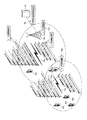
LTEでは、サービスエリアの拡大、ホットスポットのサポート及び電波不良エリア対策などのために、中継技術が導入されている。図17は、LTEの中継技術について説明する図である。
(LTE relay technology)
In LTE, relay technology has been introduced to expand service areas, support hot spots, and deal with poor radio wave areas. FIG. 17 is a diagram illustrating LTE relay technology.
図17に示すように、移動局装置UE(User Equipment)1a〜1cは中継ノードRN(Relay Node)と呼ばれる中継局装置2a〜2cと通信し、中継局装置2a〜2cは親基地局装置DeNB(Doner eNodeB)3aと通信する。
As shown in FIG. 17, mobile station apparatuses UE (User Equipment) 1 a to 1 c communicate with
中継局装置2a〜2cは無線バックホール回線(Unインターフェース)4a〜4cを経由して親基地局装置3aに無線接続され、移動局装置1a〜1cは無線アクセス回線(Uuインターフェース)5a〜5cを経由して中継局装置2a〜2cに接続する。
The
親基地局装置3aは複数の中継局装置2a〜2cに中継接続を提供するだけではなく、中継接続を経由せずに移動局装置1dと無線アクセス回線5dを経由して直接通信することもできる。その詳細は、例えば、非特許文献2、3に記載されているため、ここではその説明を省略する。
The parent
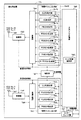
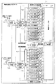
(LTE物理チャネルの構成)
図18は、LTE物理チャンネルの構成について示す図である。図18に示すように、基地局装置3aと移動局装置1dとは、無線アクセス回線5dにより接続される。無線アクセス回線5dには、複数のLTEの物理チャネルが含まれる。
(LTE physical channel configuration)
FIG. 18 is a diagram illustrating a configuration of the LTE physical channel. As shown in FIG. 18, the
LTE物理チャネルは、基地局装置3aから移動局装置1dへの情報送信に用いられる下り回線における物理下り回線チャネルと、移動局装置から基地局装置への情報送信に用いられる上り回線における物理上り回線チャネルがある。
The LTE physical channel includes a physical downlink channel in the downlink used for information transmission from the
物理下り回線チャネルには、下り回線参照信号DLRS(Downlink Reference Signals)、同期シグナルSS(Synchronization Signals)、物理報知チャネルPBCH(Physical Broadcast Channel)、物理下り回線制御チャネルPDCCH(Physical Downlink Control Channel)、物理下り回線共用チャネルPDSCH(Physical Downlink Shared Channel)、物理マルチキャストチャネルPMCH(Physical Multicast Channel)、物理制御フォーマットインディケータチャネルPCFICH(Physical Control Format Indicator Channel)、及び、物理HARQ(Hybrid Automatic Repeat Request)インディケータチャネルPHICH(Physical Hybrid ARQ Indicator Channel)が含まれる。 Physical downlink channels include downlink reference signals DLRS (Downlink Reference Signals), synchronization signals SS (Synchronization Signals), physical broadcast channel PBCH (Physical Broadcast Channel), physical downlink control channel PDCCH (Physical Downlink Control Channel), physical Downlink shared channel PDSCH (Physical Downlink Shared Channel), physical multicast channel PMCH (Physical Multicast Channel), physical control format indicator channel PCFICH (Physical Control Format Indicator Channel), and physical HARQ (Hybrid Automatic Repeat Request) indicator channel PHICH ( Physical Hybrid ARQ Indicator Channel).
物理上り回線チャネルには、上り回線参照信号ULRS(Uplink Reference Signals)、物理上り回線制御チャネルPUCCH(Physical Uplink Control Channel)、物理上り回線共用チャネルPUSCH(Physical Uplink Shared Channel)、及び、物理ランダムアクセスチャネルPRACH(Physical Random Access Channel)が含まれる。各物理チャネルの詳細構成と機能は、例えば、非特許文献2や他のLTE仕様書に記載されているため、ここではそれらの説明を省略する。
The physical uplink channel includes an uplink reference signal ULRS (Uplink Reference Signals), a physical uplink control channel PUCCH (Physical Uplink Control Channel), a physical uplink shared channel PUSCH (Physical Uplink Shared Channel), and a physical random access channel. PRACH (Physical Random Access Channel) is included. The detailed configuration and function of each physical channel are described in, for example, Non-Patent
移動通信ネットワークでは、災害時に輻輳が発生するという問題がある。それだけでなく、停電や通信設備が破壊されて通信が途絶したり、基地局装置が停波状態となって、通信が途絶するエリアが生じたりすることもある。このような場合、何らかの手段で、移動局装置が外部と通信を行うことを可能とする通信継続エリアを設置することが要望される。 In a mobile communication network, there is a problem that congestion occurs during a disaster. In addition, there may be a case where communication is interrupted due to a power failure or a communication facility being destroyed, or an area where communication is interrupted due to the base station device being stopped. In such a case, it is desired to install a communication continuation area that allows the mobile station apparatus to communicate with the outside by some means.
また、基地局装置のサービスエリアが点在する山岳地帯、人口過疎地帯などにおいてサービスエリアエッジの無線電波が弱かったり、気候により電波減衰が増加したり、周辺電波の干渉が発生したりするなどの影響で、無線電波が不安定となることがある。例えば、悪天候によって山岳事故などが発生した場合、サービスエリアエッジにおいて臨時に通信を確保することを可能とするサービス拡大エリアを増設することが要望される。 In addition, the radio waves at the edge of the service area are weak in mountainous areas and depopulated areas where the service area of the base station device is scattered, radio wave attenuation increases due to the climate, interference of surrounding radio waves, etc. The radio wave may become unstable due to the influence. For example, when a mountain accident or the like occurs due to bad weather, it is desired to add a service expansion area that can temporarily secure communication at the service area edge.
また、基地局装置のサービスエリア内であってもビルの内部やビルの陰、地下などでは無線電波が弱かったり、気候により電波減衰が増加したり、周辺電波の干渉が発生したり、特定エリアにおけるユーザ数が急増したりするなどの影響で、無線電波が不安定となることがある。このような場合も、電波の品質を改善した電波改善エリアを確保することが要望される。 Even within the service area of a base station device, radio waves are weak inside buildings, behind buildings, underground, etc., radio wave attenuation increases due to the climate, interference with surrounding radio waves occurs, Wireless radio waves may become unstable due to the sudden increase in the number of users in Even in such a case, it is desired to secure a radio wave improvement area with improved radio wave quality.
また、サービスエリアエッジにおいてイベントが開催されており、ユーザ数が増加したような場合、隣接基地局装置に対する干渉が増加することがある。このような場合も、干渉を低減するよう要求する隣接基地局装置からの通知に対して、干渉を低減した干渉低減エリアを設置することが要望される。 Also, when an event is held at the service area edge and the number of users increases, interference with adjacent base station apparatuses may increase. Even in such a case, it is desired to install an interference reduction area in which interference is reduced in response to a notification from an adjacent base station apparatus that requests to reduce interference.
上記のような問題に対して、アドホックネットワークを利用することが検討されている。アドホックネットワークとは、通信インフラを利用せず、端末相互が通信し合うことで形成されるネットワークである。 In order to solve the above problems, it has been studied to use an ad hoc network. An ad hoc network is a network formed by terminals communicating with each other without using a communication infrastructure.
上記の通信継続エリア、サービス拡大エリア、電波改善エリア、または干渉低減エリアにおいてアドホックネットワークを構築し、アドホックネットワークを経由して、各エリアにおける移動局装置と基地局装置との間の通信を中継することにより、無線接続の維持が可能となる。 An ad hoc network is constructed in the above communication continuation area, service expansion area, radio wave improvement area, or interference reduction area, and the communication between the mobile station device and the base station device in each area is relayed via the ad hoc network. As a result, the wireless connection can be maintained.
そして現在、各サービスエリアから他の移動局装置を経由して、基地局装置と接続できる通信経路をどうやって見つけるか、各サービスエリア内にある移動局装置の位置管理をどうするか、各移動局装置の相互連携機能、中継機能をどう実現するかが検討課題となっている。 Then, how to find a communication path that can be connected to the base station device from each service area via another mobile station device, how to manage the location of the mobile station device in each service area, each mobile station device It is a subject of study how to realize the mutual cooperation function and relay function.
本発明は、上記課題に鑑み、複雑なアドホックネットワークシステムを導入せずに、現状のLTE規格に規定されている無線アクセス方法、通信プロトコルを利用して、通信継続エリア、サービス拡大エリア、電波改善エリア、または干渉低減エリアを設置することにより、移動局装置の送受信信号を中継することを可能とする無線中継通信システム、無線通信システム、移動局装置データベース、基地局装置、無線局装置、集積回路、コンピュータプログラム、および、そのコンピュータプログラムを記録したことを特徴とするコンピュータが読み取り可能な記録媒体を提供することを目的とする。 In view of the above problems, the present invention uses a wireless access method and a communication protocol defined in the current LTE standard without introducing a complicated ad hoc network system, and continues communication area, service expansion area, and radio wave improvement. Wireless relay communication system, wireless communication system, mobile station device database, base station device, wireless station device, integrated circuit capable of relaying transmission / reception signal of mobile station device by installing area or interference reduction area Another object of the present invention is to provide a computer program and a computer-readable recording medium characterized by recording the computer program.
上記課題を解決する為に、本発明の第1の技術手段は、基地局装置、移動局装置、無線局装置により構成される無線中継通信システムであって、前記無線局装置は、前記移動局装置の1つとして前記基地局装置と通信を行う移動局装置モードと、前記基地局装置と前記移動局装置の通信を中継する中継局装置モードのいずれかにモードを切り替えるモード切替制御信号を受信し、該モード切替制御信号により前記移動局装置モードへの前記モードの切り替えが指示された場合に、前記移動局装置の1つとして前記基地局装置と通信を行い、前記モード切替制御信号により前記中継局装置モードへの前記モードの切り替えが指示された場合に、前記基地局装置と前記移動局装置の通信を中継することを特徴とする。 In order to solve the above problems, a first technical means of the present invention is a radio relay communication system including a base station apparatus, a mobile station apparatus, and a radio station apparatus, wherein the radio station apparatus includes the mobile station A mode switching control signal for switching the mode to one of a mobile station apparatus mode for communicating with the base station apparatus and a relay station apparatus mode for relaying communication between the base station apparatus and the mobile station apparatus is received as one of the apparatuses. Then, when switching to the mobile station apparatus mode is instructed by the mode switching control signal, the mode switching control signal communicates with the base station apparatus as one of the mobile station apparatuses, and the mode switching control signal When switching to the relay station apparatus mode is instructed, communication between the base station apparatus and the mobile station apparatus is relayed.
本発明の第2の技術手段は、第1の技術手段において、前記基地局装置は、前記モード切替制御信号を前記無線局装置に送信し、前記無線局装置は、前記基地局装置により送信された前記モード切替制御信号を受信することを特徴とする。 According to a second technical means of the present invention, in the first technical means, the base station apparatus transmits the mode switching control signal to the radio station apparatus, and the radio station apparatus is transmitted by the base station apparatus. The mode switching control signal is received.
本発明の第3の技術手段は、第1の技術手段において、前記無線局装置は、前記基地局装置以外の外部装置により送信された前記モード切替制御信号、または、ユーザにより入力された前記モード切替制御信号を受信することを特徴とする。 According to a third technical means of the present invention, in the first technical means, the radio station apparatus transmits the mode switching control signal transmitted by an external apparatus other than the base station apparatus or the mode input by a user. A switching control signal is received.
本発明の第4の技術手段は、第2の技術手段において、前記無線局装置は、前記移動局装置モードと前記中継局装置モードとの間でモードを切り替えることが可能であることを示すモード切替能力情報を前記基地局装置に送信し、前記基地局装置は、前記モード切替能力情報に基づいて、前記無線局装置に前記モード切替制御信号を送信することを特徴とする。 According to a fourth technical means of the present invention, in the second technical means, the radio station apparatus is capable of switching modes between the mobile station apparatus mode and the relay station apparatus mode. Switching capability information is transmitted to the base station device, and the base station device transmits the mode switching control signal to the radio station device based on the mode switching capability information.
本発明の第5の技術手段は、第2の技術手段において、前記無線局装置は、該無線局装置の位置を示す位置情報を前記基地局装置に送信し、前記基地局装置は、前記位置情報に基づいて前記無線局装置に前記モード切替制御信号を送信することを特徴とする。 According to a fifth technical means of the present invention, in the second technical means, the radio station apparatus transmits position information indicating a position of the radio station apparatus to the base station apparatus, and the base station apparatus The mode switching control signal is transmitted to the radio station apparatus based on information.
本発明の第6の技術手段は、第2の技術手段において、前記基地局装置は、該基地局装置と前記移動局装置との間の通信を可能とするエリアを決定し、前記エリア内にある前記移動局装置との間の通信を中継する無線局装置を選択し、選択した無線局装置に前記モード切替制御信号を送信することを特徴とする。 According to a sixth technical means of the present invention, in the second technical means, the base station apparatus determines an area in which communication between the base station apparatus and the mobile station apparatus is possible, and the area is within the area. A radio station apparatus that relays communication with a certain mobile station apparatus is selected, and the mode switching control signal is transmitted to the selected radio station apparatus.
本発明の第7の技術手段は、ネットワーク制御部、基地局装置、移動局装置、無線局装置により構成される無線通信システムであって、前記ネットワーク制御部は、前記基地局装置と前記移動局装置の通信を中継させる無線局装置を選択し、該無線局装置を管理する前記基地局装置に中継局装置設置要求信号を送信し、前記基地局装置は、該中継局装置設置要求信号を受信した場合、前記ネットワーク制御部により選択された無線局装置に対して、前記移動局装置の1つとして前記基地局装置と通信を行う移動局装置モードから、前記基地局装置と前記移動局装置の通信を中継する中継局装置モードに前記無線局装置のモードを切り替えるモード切替制御信号を送信し、前記無線局装置は、前記モード切替制御信号により前記中継局装置モードへの前記モードの切り替えが指示された場合に、前記基地局装置と前記移動局装置の通信を中継することを特徴とする。 A seventh technical means of the present invention is a radio communication system including a network control unit, a base station device, a mobile station device, and a radio station device, wherein the network control unit includes the base station device and the mobile station. A radio station apparatus that relays communication of the apparatus is selected, a relay station apparatus installation request signal is transmitted to the base station apparatus that manages the radio station apparatus, and the base station apparatus receives the relay station apparatus installation request signal In this case, for the radio station device selected by the network control unit, from the mobile station device mode that communicates with the base station device as one of the mobile station devices, the base station device and the mobile station device A mode switching control signal for switching the mode of the radio station apparatus is transmitted to a relay station apparatus mode for relaying communication, and the radio station apparatus transmits the mode of the relay station apparatus according to the mode switching control signal. When the switching of the mode to is instructed, characterized in that relays communication of the mobile station apparatus and the base station apparatus.
本発明の第8の技術手段は、基地局装置と移動局装置の通信の中継管理に用いられる移動局装置データベースであって、前記基地局装置と通信を行う移動局装置モードと、前記基地局装置と前記移動局装置の通信を中継する中継局装置モードのいずれかにモードを切り替えるモード切替能力が各移動局装置にあるか否かを示すモード切替能力情報と、各移動局装置の位置情報とを記憶し、前記中継を行う移動局装置は、前記モード切替能力情報と前記位置情報とに基づいて決定されることを特徴とする。 An eighth technical means of the present invention is a mobile station apparatus database used for relay management of communication between a base station apparatus and a mobile station apparatus, wherein the mobile station apparatus mode communicates with the base station apparatus, and the base station Mode switching capability information indicating whether or not each mobile station device has mode switching capability to switch the mode to any one of relay station device modes that relay communication between the device and the mobile station device, and position information of each mobile station device And the mobile station apparatus that performs the relay is determined based on the mode switching capability information and the position information.
本発明の第9の技術手段は、基地局装置、移動局装置、無線局装置により構成される無線中継通信システムの基地局装置であって、前記移動局装置の1つとして前記無線局装置に前記基地局装置と通信を行わせる移動局装置モードと、前記無線局装置に前記基地局装置と前記移動局装置の通信を中継させる中継局装置モードのいずれかに、前記無線局装置のモードを切り替えるモード切替制御部を備えることを特徴とする。 A ninth technical means of the present invention is a base station apparatus of a radio relay communication system including a base station apparatus, a mobile station apparatus, and a radio station apparatus, wherein the radio station apparatus is one of the mobile station apparatuses. Either the mobile station device mode for communicating with the base station device or the relay station device mode for allowing the wireless station device to relay communication between the base station device and the mobile station device, the mode of the wireless station device A mode switching control unit for switching is provided.
本発明の第10の技術手段は、第9の技術手段において、前記基地局装置は、前記移動局装置モードと前記中継局装置モードのいずれかにモードを切り替えることが可能であることを示すモード切替能力情報を前記無線局装置から受信し、前記モード切替制御部は、前記モード切替能力情報に基づいて、前記無線局装置のモードを切り替えることを特徴とする。 A tenth technical means of the present invention is the mode in the ninth technical means, wherein the base station apparatus can switch the mode to either the mobile station apparatus mode or the relay station apparatus mode. The switching capability information is received from the radio station device, and the mode switching control unit switches the mode of the radio station device based on the mode switching capability information.
本発明の第11の技術手段は、第9の技術手段において、前記基地局装置は、前記無線局装置の位置を示す位置情報を受信し、前記モード切替制御部は、前記位置情報に基づいて、前記無線局装置のモードを切り替えることを特徴とする。 According to an eleventh technical means of the present invention, in the ninth technical means, the base station apparatus receives position information indicating a position of the radio station apparatus, and the mode switching control unit is based on the position information. The mode of the radio station apparatus is switched.
本発明の第12の技術手段は、第9の技術手段において、前記モード切替制御部は、前記基地局装置と前記移動局装置との間の通信を可能とするエリアを決定し、該エリア内にある前記無線局装置のモードを切り替えることを特徴とする。 A twelfth technical means of the present invention is the ninth technical means, wherein the mode switching control unit determines an area in which communication between the base station apparatus and the mobile station apparatus is possible, The mode of the said radio station apparatus in is switched.
本発明の第13の技術手段は、第9〜第12のいずれかの技術手段において、前記基地局装置は、前記無線局装置のモードを切り替えるモード切替制御信号を前記無線局装置に送信することを特徴とする。 According to a thirteenth technical means of the present invention, in any one of the ninth to twelfth technical means, the base station device transmits a mode switching control signal for switching a mode of the radio station device to the radio station device. It is characterized by.
本発明の第14の技術手段は、基地局装置、移動局装置、無線局装置により構成される無線中継通信システムの無線局装置であって、前記移動局装置の1つとして前記基地局装置と通信を行う移動局装置モードと、前記基地局装置と前記移動局装置の通信を中継する中継局装置モードのいずれかにモードを切り替えるモード切替処理部と、前記移動局装置モードにおいては前記移動局装置の1つとして前記基地局装置と通信を行い、前記中継局装置モードにおいては前記基地局装置と前記移動局装置の通信を中継する制御部と、を備えることを特徴とする。 A fourteenth technical means of the present invention is a radio station apparatus of a radio relay communication system constituted by a base station apparatus, a mobile station apparatus, and a radio station apparatus, and the base station apparatus and one of the mobile station apparatuses A mobile station apparatus mode for performing communication; a mode switching processing unit for switching the mode to any one of relay station apparatus modes for relaying communication between the base station apparatus and the mobile station apparatus; and in the mobile station apparatus mode, the mobile station A control unit that communicates with the base station device as one of the devices and relays communication between the base station device and the mobile station device in the relay station device mode.
本発明の第15の技術手段は、第14の技術手段において、前記無線局装置は、前記移動局装置モードと前記中継局装置モードのいずれかにモードを切り替えることが可能であることを示すモード切替能力情報を前記基地局装置に送信することを特徴とする。 A fifteenth technical means of the present invention is the mode showing that in the fourteenth technical means, the radio station apparatus can switch between the mobile station apparatus mode and the relay station apparatus mode. The switching capability information is transmitted to the base station apparatus.
本発明の第16の技術手段は、第14の技術手段において、前記無線局装置は、前記無線局装置の位置を示す位置情報を前記基地局装置に送信することを特徴とする。 According to a sixteenth technical means of the present invention, in the fourteenth technical means, the radio station apparatus transmits position information indicating a position of the radio station apparatus to the base station apparatus.
本発明の第17の技術手段は、第14〜第16のいずれかの技術手段において、前記無線局装置は、前記無線局装置のモードを切り替えるモード切替制御信号を前記基地局装置から受信し、前記モード切替処理部は、前記モード切替制御信号に基づいて、前記モードを切り替えることを特徴とする。 According to a seventeenth technical means of the present invention, in any one of the fourteenth to sixteenth technical means, the radio station device receives a mode switching control signal for switching a mode of the radio station device from the base station device, The mode switching processing unit switches the mode based on the mode switching control signal.
本発明の第18の技術手段は、基地局装置、移動局装置、無線局装置により構成される無線中継通信システムの基地局装置が備える集積回路であって、前記移動局装置の1つとして前記基地局装置と通信を行わせる移動局装置モードと、前記基地局装置と前記移動局装置の通信を中継させる中継局装置モードのいずれかに、前記無線局装置のモードを切り替えるモード切替制御部を備えることを特徴とする。 An eighteenth technical means of the present invention is an integrated circuit included in a base station apparatus of a radio relay communication system including a base station apparatus, a mobile station apparatus, and a radio station apparatus, and the integrated circuit is provided as one of the mobile station apparatuses. A mode switching control unit that switches the mode of the radio station apparatus to either a mobile station apparatus mode that performs communication with a base station apparatus or a relay station apparatus mode that relays communication between the base station apparatus and the mobile station apparatus It is characterized by providing.
本発明の第19の技術手段は、基地局装置、移動局装置、無線局装置により構成される無線中継通信システムの無線局装置が備える集積回路であって、前記移動局装置の1つとして前記基地局装置と通信を行う移動局装置モードと、前記基地局装置と前記移動局装置の通信を中継する中継局装置モードのいずれかに、モードを切り替えるモード切替処理部と、前記移動局装置モードにおいては前記移動局装置の1つとして前記基地局装置と通信を行い、前記中継局装置モードにおいては前記基地局装置と前記移動局装置の通信を中継する制御部と、を備えることを特徴とする。 According to a nineteenth technical means of the present invention, there is provided an integrated circuit included in a radio station apparatus of a radio relay communication system including a base station apparatus, a mobile station apparatus, and a radio station apparatus. A mode switching processing unit for switching the mode to any one of a mobile station device mode for communicating with a base station device and a relay station device mode for relaying communication between the base station device and the mobile station device, and the mobile station device mode And a controller that performs communication with the base station device as one of the mobile station devices, and relays communication between the base station device and the mobile station device in the relay station device mode. To do.
本発明の第20の技術手段は、基地局装置、移動局装置、無線局装置により構成される無線中継通信システムの基地局装置の制御を行うコンピュータプログラムであって、前記移動局装置の1つとして前記無線局装置に前記基地局装置と通信を行わせる移動局装置モードと、前記無線局装置に前記基地局装置と前記移動局装置の通信を中継させる中継局装置モードのいずれかに、前記無線局装置のモードを切り替えるモード切替制御ステップをコンピュータに実行させることを特徴とする。 According to a twentieth technical means of the present invention, there is provided a computer program for controlling a base station apparatus of a radio relay communication system including a base station apparatus, a mobile station apparatus, and a radio station apparatus, and one of the mobile station apparatuses. As a mobile station device mode for causing the radio station device to communicate with the base station device, and a relay station device mode for causing the radio station device to relay communication between the base station device and the mobile station device, A mode switching control step for switching the mode of the radio station apparatus is executed by a computer.
本発明の第21の技術手段は、基地局装置、移動局装置、無線局装置により構成される無線中継通信システムの無線局装置の制御を行うコンピュータプログラムであって、前記移動局装置の1つとして前記基地局装置と通信を行う移動局装置モードと、前記基地局装置と前記移動局装置の通信を中継する中継局装置モードのいずれかに、前記無線局装置のモードを切り替えるモード切替処理ステップをコンピュータに実行させることを特徴とする。 A twenty-first technical means of the present invention is a computer program for controlling a radio station apparatus of a radio relay communication system including a base station apparatus, a mobile station apparatus, and a radio station apparatus, and one of the mobile station apparatuses Mode switching processing step of switching the mode of the radio station apparatus to any one of a mobile station apparatus mode for communicating with the base station apparatus and a relay station apparatus mode for relaying communication between the base station apparatus and the mobile station apparatus Is executed by a computer.
本発明の第22の技術手段は、上記コンピュータプログラムを記録したことを特徴とするコンピュータが読み取り可能な記録媒体である。 According to a twenty-second technical means of the present invention, there is provided a computer-readable recording medium on which the computer program is recorded.
本発明によれば、必要とされる通信継続エリア、サービス拡大エリア、電波改善エリア、または干渉低減エリアを設置することができるようになり、基地局装置と移動局装置との間の送受信信号を中継することが可能となる。 According to the present invention, a required communication continuation area, service expansion area, radio wave improvement area, or interference reduction area can be installed, and transmission / reception signals between the base station apparatus and the mobile station apparatus can be transmitted. It becomes possible to relay.
以下、本発明の実施形態について図面を参照して詳細に説明する。まず、3GPP規格において分類されている中継局装置の種別について説明する。 Hereinafter, embodiments of the present invention will be described in detail with reference to the drawings. First, the types of relay station apparatuses classified in the 3GPP standard will be described.
(中継局装置の種別)
3GPP規格では、中継局装置をType1とType2とに分類している。Type1の中継局装置は、基地局装置と異なる物理層固有のセル番号PIC(Physical Cell ID)、同期信号(Synchronization Signals)とリファレンス信号(Reference Signals)を送信する。移動局装置は、スケジューリング情報とHARQ フィードバックを中継局装置から直接受け取り、移動局装置の制御チャネルを中継局装置に送信する。Type1中継局装置は、移動局装置からは基地局装置eNB(eNodeB)のように見える。
(Relay station device type)
In the 3GPP standard, relay station apparatuses are classified into
一方、Type2中継局装置は固有のセル番号を持たないため、移動局装置は、基地局装置から送信された信号と中継局装置から送信された信号の違いを見分けることができない。この構成では、基地局装置から制御情報を送信し、中継局装置を経由してデータを送信することが可能であるが、3GPPではこの点に関して継続審議中である。
On the other hand, since the
また、中継局装置は、レイヤに基づき、レイヤ1中継局装置、レイヤ2中継局装置、レイヤ3中継局装置に分類することができる。
Further, relay station apparatuses can be classified into
レイヤ1中継局装置は、基地局装置からの下り回線受信RF(Radio Frequency)信号を電力増幅して移動局装置に送信するAF(Amplifier and Forward)型中継局装置である。レイヤ2中継局装置は、基地局装置からの下り回線RF信号を復調・復号後、再度符号化・変調を行い、移動局装置に送信するDF(Decode and Forward)型中継局装置である。レイヤ3中継局装置は、基地局装置からの下り回線RF信号の復調・復号処理に加えて、ユーザデータを再生してから再度無線でユーザデータ伝送を行うための処理を行い、符号化・変調後に移動局装置に送信する中継局装置である。Type1中継局装置、Type2中継局装置は、レイヤ2中継局装置またはレイヤ3中継局装置である。
The
(第1の実施形態)
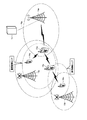
(無線中継通信システムの構成)
図1は、本発明の第1の実施形態に係る無線中継通信システムの構成の一例を示す概念図である。この無線中継通信システムは、移動局装置10a〜10d、無線局装置11a、基地局装置12a、および無線通信システムのネットワーク制御部であるMME/S−GW(Mobility Management Entity/Serving Gateway)部13を備える。
(First embodiment)
(Configuration of wireless relay communication system)
FIG. 1 is a conceptual diagram showing an example of a configuration of a wireless relay communication system according to the first embodiment of the present invention. This radio relay communication system includes
移動局装置10a〜10dは、従来の移動局装置UE(User Equipment)である。移動局装置10cは、無線アクセス回線(Uuインターフェース)を経由して基地局装置12aに接続している。
The
この無線アクセス回線(Uuインターフェース)には、図18に示したように、複数の下り回線物理チャネルあるいは信号、すなわち、DLRS、SS、PBCH、PDCCH、PDSCH、PCFICH、PHICHと、複数の上り回線物理チャネルあるいは信号、すなわち、ULRS、PUCCH、PUSCH、PRACHとが含まれる。 As shown in FIG. 18, the radio access line (Uu interface) includes a plurality of downlink physical channels or signals, that is, DLRS, SS, PBCH, PDCCH, PDSCH, PCFICH, PHICH, and a plurality of uplink physical units. Channels or signals, ie ULRS, PUCCH, PUSCH, PRACH are included.
基地局装置12aのサービスエリア内にある移動局装置10cと基地局装置12aは、LTEの仕様書に規定されている無線アクセス回線形式、通信プロトコル及びシグナリングプロシージャで動作する。一方、本発明の第1の実施形態に係る無線局装置11aは、従来の移動局装置UE機能と中継局装置RN機能の両方を備えており、中継局装置RN機能により移動局装置10a、10b、10dと基地局装置12aとの間の通信を中継する。
The
(基地局装置の構成)
図2は、本発明に係る無線中継通信システムによる中継エリアを形成する第1例を示す図である。この無線中継通信システムは、移動局装置10a〜10d、無線局装置11a〜11d、基地局装置12a〜12cおよびMME/S−GW部13を備える。
(Configuration of base station equipment)
FIG. 2 is a diagram showing a first example of forming a relay area by the wireless relay communication system according to the present invention. This radio relay communication system includes
通信継続エリア、サービス拡大エリア、電波改善エリア、または干渉低減エリアを設置する場合、図1、図2に示した基地局装置12aは、移動局装置モードと中継局装置モードの切り替えを制御するモード切替制御部12a21を用いて、無線局装置11a〜11dの移動局装置モードと中継局装置モードの間でのモードの切り替えの要否を判断する。モード切替制御部12a21については、後に詳しく説明する。
When a communication continuation area, a service expansion area, a radio wave improvement area, or an interference reduction area is installed, the
そして、基地局装置12aは、移動局装置モードから中継局装置モードへのモードの切り替えが必要と判断されたとき、無線局装置11a〜11dに移動局装置モードから中継局装置モードへのモードの切り替えを制御するモード切替制御信号を無線局装置11a〜11dに送信する。
Then, when it is determined that the mode switching from the mobile station device mode to the relay station device mode is necessary, the
無線局装置11a〜11dは移動局装置モードと中継局装置モードのいずれかにモードを切り替えるモード切替処理部11a81を用いて、移動局装置モードから中継局装置モードにモードを切り替え、中継局モードの初期接続手順を通じ、基地局装置12aに再接続する。
基地局装置12aは、図1に示したように、中継局装置モードに切り替わった無線局装置11a〜11dに対して親基地局装置となり、無線バックホール回線(Unインターフェース)14a〜14dを経由して、無線局装置11a〜11dとの接続を確立する。
As shown in FIG. 1, the
そして、無線局装置11a〜11dは、移動局装置10a〜10dの無線アクセス回線(Uuインターフェース)15a〜15dを中継する。これにより、無線局装置11a〜11dは、必要に応じて、通信継続エリア、サービス拡大エリア、干渉低減エリア、または、電波改善エリアを形成する。
The
無線バックホール回線(Unインターフェース)14a〜14dには、図18で説明した複数の下り回線物理チャネルあるいは信号(DLRS、SS、PBCH、PDCCH、PDSCH、PCFICH、PHICH)、複数の上り回線物理チャネルあるいは信号(ULRS、PUCCH、PUSCH、PRACH)以外に、後述する中継局用物理下り回線制御チャネルR−PDCCH(Relay-Physical Downlink Control Channel)が含まれる。 The wireless backhaul lines (Un interfaces) 14a to 14d include a plurality of downlink physical channels or signals (DLRS, SS, PBCH, PDCCH, PDSCH, PCFICH, PHICH), a plurality of uplink physical channels described in FIG. In addition to signals (ULRS, PUCCH, PUSCH, PRACH), a relay station physical downlink control channel R-PDCCH (Relay-Physical Downlink Control Channel) described later is included.
つぎに、基地局装置12a〜12dの構成について説明する。なお、基地局装置12a〜12dはすべて同じ構成を含んでいるので、ここでは、基地局装置12aの構成について説明する。
Next, the configuration of the
図3は、本発明の第1の実施形態に係る基地局装置12aの構成の一例を示す概念図である。基地局装置12aは、インターフェース部12a1、上位レイヤ処理部12a2、物理チャネル抽出部12a3、多重部12a4、送信部12a5、送信アンテナ部12a6、受信アンテナ部12a7、受信部12a8、多重分離部12a9、物理チャネル生成部12a10、制御部12a11を備える。
FIG. 3 is a conceptual diagram showing an example of the configuration of the
物理チャネル抽出部12a3は、ULRS(Uplink Reference Signals)抽出部12a31、PUCCH(Physical Uplink Control Channel)抽出部12a32、PUSCH(Physical Uplink Shared Channel)抽出部12a33、PRACH(Physical Random Access Channel)抽出部12a34を備える。 The physical channel extraction unit 12a3 includes an ULRS (Uplink Reference Signals) extraction unit 12a3 1 , a PUCCH (Physical Uplink Control Channel) extraction unit 12a3 2 , a PUSCH (Physical Uplink Shared Channel) extraction unit 12a3 3 , a PRACH (Physical Random Access Channel) extraction comprising a part 12a3 4.
また、物理チャネル生成部12a10は、DLRS(Downlink Reference Signals)生成部12a101、SS(Synchronization Signals)生成部12a102、PBCH(Physical Broadcast Channel)生成部12a103、PDCCH(Physical Downlink Control Channel)生成部12a104、PDSCH(Physical Downlink Shared Channel)生成部12a105、PCFICH(Physical Control Format Indicator Channel)生成部12a106、PHICH(Physical Hybrid ARQ Indicator Channel)生成部12a107、R−PDCCH(Relay Physical Downlink Control Channel)生成部12a108を備える。 The physical channel generation unit 12a10 includes a DLRS (Downlink Reference Signals) generation unit 12a10 1 , an SS (Synchronization Signals) generation unit 12a10 2 , a PBCH (Physical Broadcast Channel) generation unit 12a10 3 , and a PDCCH (Physical Downlink Control Channel) generation unit. 12a10 4 , PDSCH (Physical Downlink Shared Channel) generator 12a10 5 , PCFICH (Physical Control Format Indicator Channel) generator 12a10 6 , PHICH (Physical Hybrid ARQ Indicator Channel) generator 12a10 7 , R-PDCCH (Relay Physical Downlink Control Channel) ) comprising a generating unit 12a10 8.
インターフェース部12a1は、MME/S−GW部13に接続し、ユーザデータ及び制御データを送受信する。
The interface unit 12a1 is connected to the MME / S-
上位レイヤ処理部12a2は、インターフェース部12a1を通じて、MME/S−GW部13に接続し、上位レイヤのユーザデータおよび制御データの生成処理および抽出処理を行う。また、上位レイヤ処理部12a2は、各種の通信プロトコルおよびプロシージャ処理を行う。
The upper layer processing unit 12a2 is connected to the MME / S-
上位レイヤ処理部12a2は、移動局装置モードと中継局装置モードの間におけるモードの切り替えを制御するモード切替制御部12a21を備える。モード切替制御部12a21は、無線局装置11a〜11dについて、移動局装置モードから中継局装置モードへのモードの切り替えの要否を判断する。
Upper layer processing unit 12a2 is provided with a mode switching control unit 12a2 1 for controlling the switching of the mode between the mobile station device mode and the relay station device mode. Mode switching control unit 12a2 1, for the
そして、モード切替制御部12a21は、中継局装置モードへの切り替えが必要と判断したとき、モード切替制御信号を、物理下り回線共用チャネルPDSCHを通じて、RRC(Radio Resource Control)シグナリングにより、無線局装置11a〜11dに送信する。このモード切替制御信号については、後に詳しく説明する。 The mode switching controller 12a2 1, when it is determined that the need to switch to the relay station device mode, the mode switching control signal via the physical downlink shared channel PDSCH, the RRC (Radio Resource Control) signaling, the radio station It transmits to 11a-11d. This mode switching control signal will be described in detail later.
DLRS生成部12a101は、上位レイヤ処理部12a2から出力された制御データを用いて、所定の規則に基づき、各所定位置のリソースエレメントREに対応した参照信号データを生成し、生成した参照信号データを多重部12a4に出力する。 The DLRS generation unit 12a101 1 generates reference signal data corresponding to the resource element RE at each predetermined position based on a predetermined rule using the control data output from the higher layer processing unit 12a2, and the generated reference signal data Is output to the multiplexing unit 12a4.
SS生成部12a102は、上位レイヤ処理部12a2から出力されたセル番号PICに応じて、所定の規則に基づき、各所定位置のリソースエレメントREに対応したプライマリ同期シグナルとセカンダリ同期シグナルデータを生成し、生成したプライマリ同期シグナルとセカンダリ同期シグナルデータを多重部12a4に出力する。 SS generator 12A10 2 in accordance with the cell number PIC output from the upper layer processing unit 12a2, based on a predetermined rule, produces a primary synchronization signal and secondary synchronization signals data corresponding to the resource element RE for each predetermined position The generated primary synchronization signal and secondary synchronization signal data are output to the multiplexing unit 12a4.
PBCH生成部12a103は、上位レイヤ処理部12a2から出力された、セル内の移動局装置で共通に用いられるパラメータ(報知情報、システム情報)を用いて、所定の規則に基づき、各所定位置のリソースエレメントREに対応した上位レイヤの報知データ生成し、生成した報知データを多重部12a4に出力する。 The PBCH generation unit 12a10 3 uses parameters (broadcast information and system information) that are output from the higher layer processing unit 12a2 and are used in common in the mobile station apparatuses in the cell, based on predetermined rules, and The broadcast data of the upper layer corresponding to the resource element RE is generated, and the generated broadcast data is output to the multiplexing unit 12a4.
PDCCH生成部12a104は、上位レイヤ処理部12a2から出力されたページングデータ、ユーザデータ、上り回線ユーザデータに関連するHARQ(Hybrid automatic repeat request)データの無線リソース割り当て情報、上り回線スケジューリング許可(Uplink Scheduling Grant)などのPDCCHデータを用いて、所定の規則に基づき、各所定位置のリソースエレメントREに対応した上位レイヤの下り回線制御データを生成し、生成した下り回線制御データを多重部12a4に出力する。 PDCCH generating section 12A10 4 is paging data output from the upper layer processor 12a2, the user data, HARQ associated with the uplink user data (Hybrid automatic repeat request) the radio resource allocation information of the data, the uplink scheduling grant (Uplink Scheduling Based on a predetermined rule, upper layer downlink control data corresponding to the resource element RE at each predetermined position is generated using PDCCH data such as Grant), and the generated downlink control data is output to the multiplexing unit 12a4 .
PDSCH生成部12a105は、上位レイヤ処理部12a2から出力されたユーザデータ、制御データ、ページングデータなどを用いて、所定の規則に基づき、各所定位置のリソースブロックRBに対応した上位レイヤの下り回線共有データを生成し、生成した下り回線共有データを多重部12a4に出力する。 PDSCH generating section 12A10 5, the user data output from the upper layer processor 12a2, the control data, by using a paging data based on a predetermined rule, downlink upper layer corresponding to the resource block RB of each predetermined position The shared data is generated, and the generated downlink shared data is output to the multiplexing unit 12a4.
PCFICH生成部12a106は、上位レイヤ処理部12a2から出力されたPDCCHが占めるOFDMシンボル数のデータを用いて、所定の規則に基づき、各所定位置のリソースエレメントREに対応した上位レイヤの物理制御フォーマットインディケータチャネルPCFICHデータを生成し、生成した物理制御フォーマットインディケータチャネルPCFICHデータを多重部12a4に出力する。 PCFICH generation section 12A10 6 uses data number of OFDM symbols occupied by PDCCH output from the upper layer processing unit 12a2, based on a predetermined rule, the physical control format of the upper layer corresponding to the resource element RE for each predetermined position The indicator channel PCFICH data is generated, and the generated physical control format indicator channel PCFICH data is output to the multiplexing unit 12a4.
PHICH生成部12a107は、上位レイヤ処理部12a2から出力された上り回線ユーザデータに対するHARQのACK/NACKデータを用いて、所定の規則に基づき、各所定位置のリソースエレメントREに対応した物理HARQインディケータチャネルPHICHデータを生成し、生成した物理HARQインディケータチャネルPHICHデータを多重部12a4に出力する。 The PHICH generation unit 12a10 7 uses the HARQ ACK / NACK data for the uplink user data output from the higher layer processing unit 12a2, and based on a predetermined rule, the physical HARQ indicator corresponding to the resource element RE at each predetermined position The channel PHICH data is generated, and the generated physical HARQ indicator channel PHICH data is output to the multiplexing unit 12a4.
R−PDCCH生成部12a108は、上位レイヤ処理部12a2から出力された中継局装置の制御データを用いて、所定の規則に基づき、各所定位置のリソースブロックRBに対応した上位レイヤの物理下り回線制御チャネルR―PDCCHデータを生成し、生成した物理下り回線制御チャネルR―PDCCHデータを多重部12a4に出力する。そして、基地局装置12aは、所管の中継局装置に対して、制御データを送信する。
R-PDCCH generating section 12A10 8 uses the control data of the relay station apparatus output from the upper layer processor 12a2, based on a predetermined rule, the physical downlink upper layer corresponding to the resource block RB of each predetermined position Control channel R-PDCCH data is generated, and the generated physical downlink control channel R-PDCCH data is output to multiplexing section 12a4. Then, the
上記の各下り回線物理チャネル生成部12a101〜12a108は、上位レイヤ処理部12a2から出力されたユーザデータ、制御データに対して、スクランブリング処理(Scrambling Processing)、変調処理(Modulation Processing)、レイヤマッピング処理(Layer Mapping Processing)、プリコーディング処理(Precoding Processing)を行っている。これらの処理の詳細は、非特許文献1などのLTEの仕様書に規定されているため、ここではその説明を省略する。
Each of the downlink physical channel generation units 12a10 1 to 12a10 8 described above performs scrambling processing (Scrambling Processing), modulation processing (Modulation Processing), layer processing on user data and control data output from the upper layer processing unit 12a2. Mapping processing (Layer Mapping Processing) and precoding processing (Precoding Processing) are performed. The details of these processes are defined in the LTE specifications such as
多重部12a4は、上記の各下り回線物理チャネル生成部12a101〜12a108から送られてきた各所定位置のリソースエレメントREまたはリソースブロックRBに対応した各下り回線物理チャネルデータに対して、リソースエレメントマッピング処理(Resource Element Mapping Processing)を行い、さらに高速逆フーリエ変換IFFT(Inverse Fast Fourier Transform)、ガードインターバルGI(Guard Interval)の挿入、ディジタルアナログ変換DAC(Digital-Analog Conversion)を行ってOFDMアナログ信号を生成し、OFDMアナログ信号を送信部12a5に出力する。 The multiplexing unit 12a4 applies the resource element to each downlink physical channel data corresponding to the resource element RE or resource block RB at each predetermined position transmitted from each of the downlink physical channel generation units 12a10 1 to 12a10 8 described above. Performs mapping processing (Resource Element Mapping Processing), inserts fast inverse Fourier transform IFFT (Inverse Fast Fourier Transform), inserts guard interval GI (Guard Interval), performs digital analog conversion DAC (Digital-Analog Conversion), and outputs an OFDM analog signal And outputs the OFDM analog signal to the transmitter 12a5.
送信部12a5は、多重部12a4から出力されたOFDMアナログ信号に対し、帯域幅制限などのフィルタ処理、直交変調処理を行って所定のRF信号を生成し、さらにRF信号を所定の出力電力に増幅して送信アンテナ部12a6に出力する。 The transmission unit 12a5 performs a filtering process such as bandwidth limitation and an orthogonal modulation process on the OFDM analog signal output from the multiplexing unit 12a4 to generate a predetermined RF signal, and further amplifies the RF signal to a predetermined output power And output to the transmission antenna unit 12a6.
なお、図3には、1つの送信アンテナ部12a6および1つの送信部12a5を示したが、各下り回線物理チャネル生成部12a101〜12a108のレイヤマッピング処理に応じて、複数の送信アンテナ部および複数の送信部を備えることとしてもよい。 3 shows one transmission antenna unit 12a6 and one transmission unit 12a5, but a plurality of transmission antenna units and a plurality of transmission antenna units and a plurality of transmission antenna units are provided according to the layer mapping processing of each of the downlink physical channel generation units 12a10 1 to 12a10 8. It is good also as providing a some transmission part.
受信部12a8は、受信アンテナ部12a7から所定の上り回線物理チャネルのRF信号を受信し、増幅、周波数変換、フィルタ処理、直交復調処理などを行い、その結果得られた上り回線物理チャネル信号を多重分解部12a9に出力する。 The receiving unit 12a8 receives an RF signal of a predetermined uplink physical channel from the receiving antenna unit 12a7, performs amplification, frequency conversion, filter processing, orthogonal demodulation processing, and the like, and multiplexes the obtained uplink physical channel signal. It outputs to the decomposition part 12a9.
なお、図3には、1つの受信アンテナ部12a7および1つの受信部12a8を示したが、後述する各上り回線物理チャネル生成部12a31〜12a34のレイヤマッピング処理に応じて、複数の受信アンテナ部および複数の受信部を備えることとしてもよい。 FIG. 3 shows one receiving antenna unit 12a7 and one receiving unit 12a8. However, a plurality of receiving antennas are used according to the layer mapping processing of each of the uplink physical channel generating units 12a3 1 to 12a3 4 described later. And a plurality of receiving units.
また、図3には、送信アンテナ部12a6と受信アンテナ部12a7とを別々に示したが、FDDモードの基地局装置12aではアンテナ共用器DUP(Diplexer)を、TDDモードの基地局装置12aではアンテナ切替部SW(Switch)を用いることにより、1つの共用アンテナを使用することもできる。
3 shows the transmitting antenna unit 12a6 and the receiving antenna unit 12a7 separately. In the
多重分解部12a9は、移動局装置10a〜10dから受信した上り回線物理チャネル信号に対してアナログディジタル変換ADC(Analog-Digital Conversion)を行い、さらにOFDMシンボルタイミング検出、ガードインターバルGI除去、高速フーリエ変換FFT(Fast Fourier Transform)を行ってベースバンドデータを生成し、生成したベースバンドデータを各上り回線物理チャネル抽出部12a31〜12a34に出力する。
The demultiplexing unit 12a9 performs analog-digital conversion ADC (Analog-Digital Conversion) on the uplink physical channel signals received from the
ULRS抽出部12a31は、ベースバンドデータから、所定の規則に基づき、各所定位置のリソースエレメントREに対応したサウンディングリファレンスシグナルSRS(Sounding Reference Signal)データを抽出し、抽出したサウンディングリファレンスシグナルSRSデータを上位レイヤ処理部12a2に出力する。 ULRS extracting unit 12a3 1 from baseband data, based on a predetermined rule, to extract the sounding reference signal SRS (Sounding Reference Signal) data corresponding to the resource element RE for each position, the extracted sounding reference signal SRS data The data is output to the upper layer processing unit 12a2.
そして、上位レイヤ処理部12a2は、サウンディングリファレンスシグナルSRSのデータから上り回線チャネルのOFDMシンボルタイミングの推定、上り回線無線伝搬路状況の推定を行い、PDCCHを通じて、上り回線無線リソースのスケジューリング(リソースの割り当てや変調方式、符号化率の決定など)を行う。 Then, the upper layer processing unit 12a2 performs uplink channel OFDM symbol timing estimation and uplink radio channel condition estimation from the sounding reference signal SRS data, and uplink radio resource scheduling (resource allocation) via the PDCCH. And determination of modulation scheme and coding rate).
PUCCH抽出部12a32は、ベースバンドデータから、所定の規則に基づき、各所定位置のリソースブロックRBに対応した物理上り回線制御チャネルPUCCHデータを抽出し、抽出した物理上り回線制御チャネルPUCCHデータを上位レイヤ処理部12a2に出力する。 Top PUCCH extracting section 12a3 2 from the base band data, based on a predetermined rule, to extract the physical uplink control channel PUCCH data corresponding to the resource block RB of each place, the extracted physical uplink control channel PUCCH data The data is output to the layer processing unit 12a2.
上り回線制御チャネルPUCCHデータには、移動局装置の下り回線チャネル状態情報CSI(Channel Statement Information)や、チャネル品質識別子CQI(Channel Quality Indication)、プレコーディングマトリックス識別子PMI(Precoding Matrix Indicator)、ランク識別子RI(Rank Indicator)が含まれる。 The uplink control channel PUCCH data includes downlink channel state information CSI (Channel Statement Information), channel quality identifier CQI (Channel Quality Indication), precoding matrix identifier PMI (Precoding Matrix Indicator), rank identifier RI of the mobile station apparatus. (Rank Indicator) is included.
また、上り回線制御チャネルPUCCHデータには、下り回線トランスポートブロックに対するHARQにおけるACK/NACKを示す情報、移動局装置が上り回線データを送信するためのリソースの割り当てを要求するスケジューリング要求などの情報が含まれる。そして、上位レイヤ処理部12a2は、各種の通信プロトコルおよびプロシージャ処理を行う。 In addition, the uplink control channel PUCCH data includes information indicating ACK / NACK in HARQ for the downlink transport block, a scheduling request for requesting allocation of resources for the mobile station apparatus to transmit uplink data, and the like. included. The upper layer processing unit 12a2 performs various communication protocols and procedure processes.
PUSCH抽出部12a33は、ベースバンドデータから、所定の規則に基づき、各所定位置のリソースブロックRBに対応した物理上り共用制御チャネルPUSCHデータを抽出し、抽出した物理上り共用制御チャネルPUSCHデータを上位レイヤ処理部12a2に出力する。上り回線共用チャネルPUSCHデータには、主に上り回線のユーザデータと上り回線制御データ、下り回線の受信品質やACK/NACKなどの制御データが含まれる。 PUSCH extracting section 12a3 3 from the base band data, based on a predetermined rule, to extract the physical uplink shared control channel PUSCH data corresponding to the resource block RB of each place, the extracted upper physical uplink shared control channel PUSCH data The data is output to the layer processing unit 12a2. The uplink shared channel PUSCH data mainly includes uplink user data and uplink control data, downlink reception quality, and control data such as ACK / NACK.
PRACH抽出部12a34は、ベースバンドデータから、所定の規則に基づき、各所定位置のリソースブロックRBに対応した物理ランダムアクセスチャネルPRACHデータを抽出し、抽出した物理ランダムアクセスチャネルPRACHデータを上位レイヤ処理部12a2に出力する。 PRACH extracting unit 12a3 4 from the base band data, based on a predetermined rule, to extract the physical random access channel PRACH data corresponding to the resource block RB of each place, the extracted physical random access channel PRACH data upper layer processing To the unit 12a2.
物理ランダムアクセスチャネルPRACHデータには、移動局装置の上り回線制御チャネル未設定時の送信データのスケジューリング要求や、上り回線送信タイミングを基地局装置の受信タイミングウィンドウに合わせるために必要な送信タイミング調整情報の要求などの情報が含まれる。そして、上位レイヤ処理部により、各種の通信プロトコルおよびプロシージャ処理が行われる。 The physical random access channel PRACH data includes a transmission data scheduling request when the uplink control channel of the mobile station apparatus is not set, and transmission timing adjustment information necessary to match the uplink transmission timing with the reception timing window of the base station apparatus. This includes information such as requests. Various communication protocols and procedure processes are performed by the upper layer processing unit.
上記の各上り回線物理チャネル抽出部12a31〜12a34は、復調処理(Demodulation Processing)、復号処理(Decoding Processing)、ディスクランブリング処理(Descrambling Processing)などを行っている。これらの処理の詳細は、LTEの仕様書に規定されているため、ここではその説明を省略する。 Each of the uplink physical channel extraction units 12a3 1 to 12a3 4 performs a demodulation process, a decoding process, a descrambling process, and the like. The details of these processes are defined in the LTE specification, and therefore the description thereof is omitted here.
制御部12a11は、各ブロックの制御を行う。例えば、制御部12a11は、各ブロックのタイミング制御、オンオフ制御、上り回線無線伝搬路状況の測定、上りおよび下り回線の無線リソーススケジューリング、所定の通信プロトコルおよびプロシージャの処理などを行う。 The control unit 12a11 controls each block. For example, the control unit 12a11 performs timing control, on / off control of each block, measurement of uplink radio channel conditions, uplink and downlink radio resource scheduling, processing of predetermined communication protocols and procedures, and the like.
なお、ここでは、基地局装置12aが、OFDM信号の送受信を行う場合について説明したが、本発明はこれに限らず、基地局装置12aは、回路ブロックの機能変更により、無線局装置11aによりSC−FDMA(Single Carrier Frequency Division Multiple Access)方式で送信された上り回線信号、すなわち、図1に示した上り無線バックホール回線の物理チャネルULRS、PUCCH、PUSCH、PRACH信号を、SC−FDMA方式で受信してもよい。
In addition, although the case where the
例えば、基地局装置12aは、上り周波数帯域連続のSC−FDMA信号、または上り周波数帯域非連続のSC−FDMA(Clustered Discrete Fourier Transform Spread OFDM)信号を用いて、物理チャネルULRS、PUCCH、PUSCH、PRACH信号を受信してもよい。また、図3に示した基地局装置12aの構成は、FDDモード、またはTDDモード、またはFDD/TDDのデュアルモードのいずれに対応するものであってもよい。
For example, the
(無線局装置の構成)
つぎに、無線局装置11a〜11dの構成について説明する。なお、無線局装置11a〜11dはすべて同じ構成を含んでいるので、ここでは、無線局装置11aの構成について説明する。
(Configuration of radio station equipment)
Next, the configuration of the
本発明の第1の実施形態に係る無線局装置11aは、従来の移動局装置におけるUE(User Equipment)機能と中継局装置におけるRN(Relay Node)機能の両方を備えている。図4は、本発明の第1の実施形態に係るFDDモードの無線局装置11aの構成の一例を示す概念図である。
The
FDDモードの無線局装置11aは、送受信アンテナ部11a11、11a12、アンテナ共用器11a21、11a22、受信部11a31、11a32、送信部11a41、11a42、制御部11a5、多重分離部11a6、物理チャネル抽出部11a7、上位レイヤ処理部11a8、物理チャネル生成部11a9、多重部11a10を備える。
The
物理チャネル抽出部11a7は、ULRS(Uplink Reference Signals)抽出部11a71、PUCCH(Physical Uplink Control Channel)抽出部11a72、PUSCH(Physical Uplink Shared Channel)抽出部11a73、PRACH(Physical Random Access Channel)抽出部11a74、DLRS(Downlink Reference Signals)抽出部11a75、SS(Synchronization Signals)抽出部11a76、PBCH(Physical Broadcast Channel)抽出部11a77、PDCCH(Physical Downlink Control Channel)抽出部11a78、PDSCH(Physical Downlink Shared Channel)抽出部11a79、PCFICH(Physical Control Format Indicator Channel)抽出部11a710、PHICH(Physical Hybrid ARQ Indicator Channel)抽出部11a711、R−PDCCH(Relay Physical Downlink Control Channel)抽出部11a712を備える。
The physical channel extraction unit 11a7 includes an ULRS (Uplink Reference Signals) extraction unit 11a7 1 , a PUCCH (Physical Uplink Control Channel) extraction unit 11a7 2 , a PUSCH (Physical Uplink Shared Channel) extraction unit 11a7 3 , and a PRACH (Physical Random Access Channel) extraction. Unit 11a7 4 , DLRS (Downlink Reference Signals) extraction unit 11a7 5 , SS (Synchronization Signals) extraction unit 11a7 6 , PBCH (Physical Broadcast Channel) extraction unit 11a7 7 , PDCCH (Physical Downlink Control Channel) extraction unit 11a7 8 , PDSCH ( Physical Downlink Shared Channel) extraction unit 11a7 9 , PCFICH (Physical Control Format Indicator Channel) extraction unit 11a7 10 , PHICH (Physical Hybrid ARQ Indicator Channel) extraction unit 11a7 11 , R-PDCCH (Relay Physical Downlink Control Channel)
物理チャネル生成部11a9は、ULRS(Uplink Reference Signals)生成部11a91、PUCCH(Physical Uplink Control Channel)生成部11a92、PUSCH(Physical Uplink Shared Channel)生成部11a93、PRACH(Physical Random Access Channel)生成部11a94、DLRS(Downlink Reference Signals)生成部11a95、SS(Synchronization Signals)生成部11a96、PBCH(Physical Broadcast Channel)生成部11a97、PDCCH(Physical Downlink Control Channel)生成部11a98、PDSCH(Physical Downlink Shared Channel)生成部11a99、PCFICH(Physical Control Format Indicator Channel)生成部11a910、PHICH(Physical Hybrid ARQ Indicator Channel)生成部11a911を備える。 The physical channel generation unit 11a9 includes an ULRS (Uplink Reference Signals) generation unit 11a9 1 , a PUCCH (Physical Uplink Control Channel) generation unit 11a9 2 , a PUSCH (Physical Uplink Shared Channel) generation unit 11a9 3 , and a PRACH (Physical Random Access Channel) generation Unit 11a9 4 , DLRS (Downlink Reference Signals) generation unit 11a9 5 , SS (Synchronization Signals) generation unit 11a9 6 , PBCH (Physical Broadcast Channel) generation unit 11a9 7 , PDCCH (Physical Downlink Control Channel) generation unit 11a9 8 , PDSCH ( It comprises a Physical Downlink Shared Channel) generator 11a9 9, PCFICH (Physical Control Format Indicator Channel) generator 11a9 10, PHICH (Physical Hybrid ARQ Indicator Channel) generating unit 11a9 11.
送受信アンテナ部11a11は、図1に示した従来の移動局装置10a〜10dに対する無線信号の送信、および、移動局装置10a〜10dからの無線信号の受信に用いられる。
The transmission / reception antenna unit 11a11 11 is used for transmission of radio signals to the conventional
送受信アンテナ部11a11が移動局装置10a〜10dから受信した受信信号は、アンテナ共用器11a21に入力され、一方、アンテナ共用器11a21から出力された移動局装置10a〜10dに対する送信信号は、送受信アンテナ部11a11から送信される。
Received signal receiving
受信部11a31は、アンテナ共用器11a21により出力された移動局装置10a〜10dの上り回線信号、すなわち、図1に示した移動局装置10a〜10dと無線局装置11aの間の上り無線アクセス回線の物理チャネルULRS、PUCCH、PUSCH、PRACHの信号(FDDモードの中心周波数f1)を受信し、受信した各信号に対して増幅、周波数変換処理、直交復調処理、フィルタ処理などを行って多重分離部11a6に出力する。
Receiver 11a3 1 is uplink signal of the
送受信アンテナ11a12は、図1に示した基地局装置12aへの無線信号の送信、および、基地局装置12aからの無線信号の受信に用いられる。送受信アンテナ11a12が基地局装置12aから受信した受信信号は、アンテナ共用器11a22に入力され、一方、アンテナ共用器11a22から出力された基地局装置12aに対する送信信号は、送受信アンテナ部11a12から送信される。
Transmitting and receiving
受信部11a32は、アンテナ共用器11a22により出力された基地局装置12aの下り回線信号、すなわち、図1に示した無線局装置11aと基地局装置12aの間の下りバックホール回線の物理チャネルDLRS、SS、PBCH、PDCCH、PDSCH、PCFICH、PHICH、R−PDCCHの信号(FDDモードの中心周波数f2)を受信し、各信号に対して増幅、周波数変換処理、直交復調処理、フィルタ処理などを行って多重分離部11a6に出力する。
Receiver 11a3 2 is downlink signal of the
多重分離部11a6は、移動局装置10a〜10dおよび/または基地局装置12aからの信号に対して、アナログディジタル変換ADC(Analog-Digital Conversion)を行い、さらに各無線フレーム信号のOFDMシンボルタイミング検出、ガードインターバルGI除去、高速フーリエ変換FFT(Fast Fourier Transform)を行ってベースバンドデータを生成し、生成したベースバンドデータを各物理チャネル抽出部11a71〜11a712に出力する。
The demultiplexing unit 11a6 performs analog-digital conversion ADC (Analog-Digital Conversion) on signals from the
ULRS抽出部11a71、PUCCH抽出部11a72、PUSCH抽出部11a73、およびPRACH抽出部11a74は、それぞれ図3に示した基地局装置12aのULRS抽出部12a31、PUCCH抽出部12a32、PUSCH抽出部12a33、およびPRACH抽出部12a34と同様のものであるため、説明を省略する。
The ULRS extraction unit 11a7 1 , the PUCCH extraction unit 11a7 2 , the PUSCH extraction unit 11a7 3 , and the PRACH extraction unit 11a7 4 are respectively the ULRS extraction unit 12a3 1 , the PUCCH extraction unit 12a3 2 , and the PUSCH of the
DLRS抽出部11a75は、ベースバンドデータから、所定の規則に基づき、各所定位置のリソースエレメントREに対応したセル固有参照信号CRS(Cell Specific Reference Signals)データを抽出し、抽出したセル固有参照信号CRSデータを上位レイヤ処理部11a8に出力する。 DLRS extracting unit 11A7 5 from the base band data, based on a predetermined rule, to extract the cell-specific reference signal CRS (Cell Specific Reference Signals) data corresponding to the resource element RE for each position, the extracted cell-specific reference signal The CRS data is output to the upper layer processing unit 11a8.
そして、上位レイヤ処理部11a8は、セル固有参照信号CRSのデータから基地局装置12aからの下り回線チャネルのOFDMシンボルタイミングの推定、下り回線無線伝搬路状況の推定、また他の周辺基地局装置の電波状況測定などを行う。
Then, the upper layer processing unit 11a8 estimates the OFDM symbol timing of the downlink channel from the
SS抽出部11a76は、ベースバンドデータから、所定の規則に基づき、各所定位置のリソースエレメントREに対応したプライマリ同期シグナルとセカンダリ同期シグナルデータを抽出し、抽出したプライマリ同期シグナルとセカンダリ同期シグナルデータを上位レイヤ処理部11a8に出力する。そして、上位レイヤ処理部11a8は、同期プロシージャにより、基地局装置12aのセル番号PICを識別する。
SS extractor 11A7 6, from the baseband data, based on a predetermined rule, to extract the primary synchronization signals and secondary synchronization signals data corresponding to the resource element RE for each position, the extracted primary synchronization signals and secondary synchronization signals Data Is output to the upper layer processing unit 11a8. Then, the upper layer processing unit 11a8 identifies the cell number PIC of the
PBCH抽出部11a77は、ベースバンドデータから、所定の規則に基づき、各所定位置のリソースエレメントREに対応した上位レイヤの報知データを抽出し、抽出した報知データを上位レイヤ処理部11a8に出力する。 PBCH extraction unit 11A7 7 from baseband data, based on a predetermined rule, extracts broadcast data of each predetermined position the upper layer corresponding to the resource element RE, and outputs the extracted broadcast data to an upper layer processing unit 11a8 .
PDCCH抽出部11a78は、ベースバンドデータから、所定の規則に基づき、各所定位置のリソースエレメントREに対応したページングデータ、ユーザデータ、上り回線ユーザデータに関連するHARQ(Hybrid automatic repeat request)データの無線リソース割り当て情報、上り回線スケジューリング許可(Uplink Scheduling Grant)などのPDCCHデータを抽出し、抽出したPDCCHデータを上位レイヤ処理部11a8に出力する。 PDCCH extraction section 11A7 8 from the base band data, based on a predetermined rule, the paging data corresponding to the resource element RE for each position, the user data, HARQ associated with the uplink user data (Hybrid automatic repeat request) for data PDCCH data such as radio resource allocation information and uplink scheduling grant is extracted, and the extracted PDCCH data is output to the upper layer processing unit 11a8.
PDSCH抽出部11a79は、ベースバンドデータから、所定の規則に基づき、各所定位置のリソースエレメントRBに対応したユーザデータ、制御データ、ページングデータなどを抽出し、抽出したユーザデータ、制御データ、ページングデータなどを上位レイヤ処理部11a8に出力する。 PDSCH extraction unit 11A7 9 from the base band data, based on a predetermined rule, the user data corresponding to the resource element RB for each predetermined position, the control data, etc. to extract the paging data, the extracted user data, control data, paging Data and the like are output to the upper layer processing unit 11a8.
PCFICH抽出部11a710は、ベースバンドデータから、所定の規則に基づき、各所定位置のリソースエレメントREに対応したPDCCHが占めるOFDMシンボル数のデータを抽出し、抽出したOFDMシンボル数のデータを上位レイヤ処理部11a8に出力する。 PCFICH extractor 11A7 10 from baseband data, based on a predetermined rule, to extract the data of the number of OFDM symbols occupied by the PDCCH corresponding to the resource element RE for each position, the extracted OFDM symbol data of the number of upper layer The data is output to the processing unit 11a8.
PHICH抽出部11a711は、ベースバンドデータから、所定の規則に基づき、各所定位置のリソースエレメントREに対応した上り回線ユーザデータに対するHARQのACK/NACKデータを抽出し、抽出したACK/NACKデータを上位レイヤ処理部11a8に出力する。 The PHICH extraction unit 11a7 11 extracts HARQ ACK / NACK data for uplink user data corresponding to the resource element RE at each predetermined position from the baseband data based on a predetermined rule, and extracts the extracted ACK / NACK data. The data is output to the upper layer processing unit 11a8.
R−PDCCH抽出部11a712は、ベースバンドデータから、所定の規則に基づき、各所定位置のリソースエレメントRBに対応した中継局装置の制御データを抽出し、抽出した制御データを上位レイヤ処理部11a8に出力する。 R-PDCCH extraction section 11A7 12 from baseband data, based on a predetermined rule, extracts control data of the relay station apparatus corresponding to the resource element RB for each predetermined position, the upper layer processing the extracted control data section 11a8 Output to.
上記の各物理チャネル抽出部11a71〜11a712は、復調処理(Demodulation Processing)、復号処理(Decoding Processing)、ディスクランブリング処理(Descrambling Processing)などを行っている。これらの処理の詳細は、LTEの仕様書に規定されているため、ここではその説明を省略する。 Each physical channel extracting unit 11a7 1 ~11a7 12 described above, demodulation processing (stands for demodulation Processing), decoding (Decoding Processing), is performed such descrambling process (Descrambling Processing). The details of these processes are defined in the LTE specification, and therefore the description thereof is omitted here.
上位レイヤ処理部11a8は、アプリケーション処理部(図示せず)などと連携して、上位レイヤのユーザデータ及び制御データの生成処理および抽出処理を行う。また、上位レイヤ処理部11a8は、各種の通信プロトコルおよびプロシージャ処理を行う。 The upper layer processing unit 11a8 performs generation processing and extraction processing of upper layer user data and control data in cooperation with an application processing unit (not shown). The upper layer processing unit 11a8 performs various communication protocols and procedure processes.
上位レイヤ処理部11a8は、移動局装置モードと中継局装置モードの切り替えを制御するモード切替処理部11a81を備える。そして、モード切替処理部11a81は、基地局装置12aの物理下り回線共用チャネルPDSCHを通じて、RRC(Radio Resource Control)シグナリング信号に含まれるモード切替制御信号を受信した場合、無線局装置11aのモードを移動局装置モードから中継局装置モードに切り替える。モード切替制御信号については、後に詳しく説明する。
Upper layer processing unit 11A8 includes a mode switching unit 11A8 1 for controlling the switching of the relay station device mode and the mobile station device mode. The mode switching section 11A8 1, through the physical downlink shared channel PDSCH of the
ULRS生成部11a91は、上位レイヤ処理部11a8から出力された制御データを用いて、所定の規則に基づき、各所定位置のリソースエレメントREに対応したサウンディングリファレンスシグナルSRS(Sounding Reference Signal)データを生成し、生成したサウンディングリファレンスシグナルSRSデータを多重部11a10に出力する。 ULRS generator 11A9 1 is generated using the control data outputted from the upper layer processor 11A8, based on a predetermined rule, the sounding reference signal SRS (Sounding Reference Signal) data corresponding to the resource element RE for each predetermined position The generated sounding reference signal SRS data is output to the multiplexing unit 11a10.
PUCCH生成部11a92は、上位レイヤ処理部11a8から出力された上位レイヤの上り回線制御データを用いて、所定の規則に基づき、各所定位置のリソースブロックRBに対応した物理上り回線制御チャネルPUCCHデータを生成し、生成した物理上り回線制御チャネルPUCCHデータを多重部11a10に出力する。 PUCCH generation section 11A9 2 uses the uplink control data of the upper layer output from the upper layer processing unit 11A8, based on a predetermined rule, the physical uplink control channel PUCCH data corresponding to the resource block RB of each predetermined position And the generated physical uplink control channel PUCCH data is output to the multiplexing unit 11a10.
PUSCH生成部11a93は、上位レイヤ処理部11a8から出力された上位レイヤの上り回線共用データを用いて、所定の規則に基づき、各所定位置のリソースブロックRBに対応した物理上り回線共用制御チャネルPUSCHデータを生成し、生成した物理上り回線共用制御チャネルPUSCHデータを多重部11a10に出力する。 PUSCH generation unit 11A9 3, using the uplink shared data of the upper layer output from the upper layer processing unit 11A8, based on a predetermined rule, the physical uplink shared control channel corresponding to the resource block RB of each predetermined position PUSCH Data is generated, and the generated physical uplink shared control channel PUSCH data is output to the multiplexing unit 11a10.
PRACH生成部11a94は、上位レイヤ処理部11a8から出力された物理ランダムアクセスチャネルPRACHデータを用いて、所定の規則に基づき、各所定位置のリソースブロックRBに対応した物理ランダムアクセスチャネルPRACHデータを生成し、生成した物理ランダムアクセスチャネルPRACHデータを多重部11a10に出力する。 PRACH generator 11A9 4 is generated by using the physical random access channel PRACH data output from the upper layer processor 11A8, based on a predetermined rule, a physical random access channel PRACH data corresponding to the resource block RB of each predetermined position Then, the generated physical random access channel PRACH data is output to the multiplexing unit 11a10.
DLRS生成部11a95、SS生成部11a96、PBCH生成部11a97、PDCCH生成部11a98、PDSCH生成部11a99、PCFICH生成部11a910、およびPHICH生成部11a911はそれぞれ、図3に示した基地局装置12aにおけるDLRS生成部12a101、SS生成部12a102、PBCH生成部12a103、PDCCH生成部12a104、PDSCH生成部12a105、PCFICH生成部12a106、およびPHICH生成部12a107と同様のものであるため、説明を省略する。
The DLRS generator 11a9 5 , SS generator 11a9 6 , PBCH generator 11a9 7 , PDCCH generator 11a9 8 , PDSCH generator 11a9 9 , PCFICH generator 11a9 10 , and PHICH generator 11a9 11 are shown in FIG. Similar to the DLRS generator 12a10 1 , SS generator 12a10 2 , PBCH generator 12a10 3 , PDCCH generator 12a10 4 , PDSCH generator 12a10 5 , PCFICH generator 12a10 6 , and PHICH generator 12a10 7 in the
上記の各物理チャネル生成部11a91〜11a912は、上位レイヤ処理部11a8からのユーザデータ、制御データに対して、スクランブリング処理(Scrambling Processing)、変調処理(Modulation Processing)、レイヤマッピング処理(Layer Mapping Processing)、プリコーディング処理(Precoding Processing)を行っている。これらの処理の詳細は、非特許文献1などのLTEの仕様書に規定されているため、ここではその説明を省略する。
Each physical channel generating unit 11a9 1 ~11a9 12 described above, the user data from the upper layer processing unit 11A8, the control data, scrambling processing (Scrambling Processing), modulation processing (Modulation Processing), layer mapping processing (Layer Mapping Processing) and precoding processing. The details of these processes are defined in the LTE specifications such as
多重部11a10は、上記の各上り回線物理チャネル生成部から送られてきた各所定位置のリソースエレメントREまたはリソースブロックRBに対応した各下り回線物理チャネルデータに対して、リソースエレメントマッピング処理(Resource Element Mapping Processing)を行い、さらに高速逆フーリエ変換IFFT(Inverse Fast Fourier Transform)、ガードインターバルGI(Guard Interval)の挿入、ディジタルアナログ変換DAC(Digital-Analog Conversion)を行ってOFDMアナログ信号を生成し、生成したOFDMアナログ信号を、移動局装置10a〜10dおよび/または基地局装置12aへの送信信号として送信部11a41、11a42に出力する。
The multiplexing unit 11a10 performs resource element mapping processing (Resource Element) on each downlink physical channel data corresponding to the resource element RE or resource block RB at each predetermined position sent from each uplink physical channel generation unit. Generates an OFDM analog signal by performing mapping processing, and performing fast inverse Fourier transform IFFT (Inverse Fast Fourier Transform), insertion of guard interval GI (Guard Interval), digital analog conversion DAC (Digital-Analog Conversion) The transmitted OFDM analog signal is output to the transmission units 11a4 1 and 11a4 2 as a transmission signal to the
送信部11a42は、多重部11a10から出力された移動局装置10a〜10dの下り回線信号、すなわち、図1に示した移動局装置10a〜10dと無線局装置11aの間の下り無線アクセス回線の物理チャネルDLRS、SS、PBCH、PDCCH、PDSCH、PCFICH、PHICHのOFDMアナログ信号に対し、帯域幅制限などのフィルタ処理、直交変調処理を行って所定のRF信号に変換し、さらにRF信号を所定の出力電力に増幅してアンテナ共用器11a21に送る(FDDモードの中心周波数f2)。
Transmitting portion 11a4 2 is downlink signal of the
送信部11a41は、多重部11a10から出力された基地局装置12aの上り回線信号、すなわち、図1に示した無線局装置11aと基地局装置12aの間の上りバックホール回線の物理チャネルULRS、PUCCH、PUSCH、PRACHのOFDMアナログ信号に対し、帯域幅制限などのフィルタ処理、直交変調処理を行って所定のRF信号に変換し、さらにRF信号を所定の出力電力に増幅してアンテナ共用器11a21に送る(FDDモードの中心周波数f1)。
Transmitting portion 11a4 1 is uplink signal in the
制御部11a5は、各ブロックの制御を行う。例えば、制御部11a5は、各ブロックのタイミング制御、オンオフ制御、上り回線無線伝搬路状況の測定、無線リソーススケジューリング、所定の通信プロトコル及びプロシージャの処理などを行う。 The control unit 11a5 controls each block. For example, the control unit 11a5 performs timing control, on / off control of each block, measurement of uplink radio channel conditions, radio resource scheduling, processing of a predetermined communication protocol and procedure, and the like.
なお、ここでは、無線局装置11aが、OFDM信号の送受信を行う場合について説明したが、本発明はこれに限らず、無線局装置11aは、回路ブロックの機能変更により、移動局装置10a〜10dの上り回線信号、すなわち、図1に示した移動局装置10a〜10dと無線局装置11aの間の上り無線アクセス回線の物理チャネルULRS、PUCCH、PUSCH、PRACH信号、および、無線局装置11aの上り回線信号、すなわち、図1に示した無線局装置11aと基地局装置12aの間の上り無線アクセス回線の物理チャネルULRS、PUCCH、PUSCH、PRACH信号を、SC−FDMA(Single Carrier Frequency Division Multiple Access)方式で送受信してもよい。
In addition, although the case where the
例えば、無線局装置11aは、上り連続のSC−FDMA信号、または非連続のSC−FDMA(Clustered Discrete Fourier Transform Spread OFDM)信号を用いて、移動局装置10a〜10dと無線局装置11aの間の上り無線アクセス回線の物理チャネルULRS、PUCCH、PUSCH、PRACH信号、および、無線局装置11aと基地局装置12aの間の上り無線アクセス回線の物理チャネルULRS、PUCCH、PUSCH、PRACH信号を送受信してもよい。
For example, the
つぎに、本発明の第1の実施形態に係るTDDモードの無線局装置11aの構成について説明する。図5は、本発明の第1の実施形態に係るTDDモードの無線局装置11aの構成の一例を示す概念図である。
Next, the configuration of the TDD mode
TDDモードの無線局装置11aは、送受信アンテナ部11a11、アンテナ切替部11a12を除いて、図4に一例を示したFDDモードの無線局装置11aの構成と同様のものであるため、詳細な説明を省略する。
The TDD mode
送受信アンテナ11a11は、時分割方式による無線信号の送受信、具体的には、図1に示した移動局装置10a〜10dに対する無線信号(TDDモードの中心周波数f1)の送信、移動局装置10a〜10dからの無線信号(TDDモードの中心周波数f1)の受信、または、基地局装置12aに対する無線信号(TDDモードの中心周波数f1)の送信、基地局装置12aからの無線信号(TDDモードの中心周波数f1)の受信に用いられる。
The transmission / reception antenna 11a11 transmits and receives radio signals by a time division method, specifically, transmission of radio signals (center frequency f1 in TDD mode) to the
送受信アンテナ11a11が移動局装置10a〜10d、または、基地局装置12aから受信した受信信号は、アンテナ切替部11a12に入力され、一方、アンテナ切替部11a12から出力された送信信号は、送受信アンテナ11a11から送信される。
The reception signal received by the transmission / reception antenna 11a11 from the
アンテナ切替部11a11は、制御部11a5から出力される制御信号により、送受信アンテナ11a11と接続する処理部を、受信部11a32と送信部11a41との間で切り替える。 Antenna switching unit 11A11 by the control signal outputted from the control unit 11a5, the processing unit connected to the transmitting and receiving antenna 11A11, switching between a receiving portion 11a3 2 and the transmission portion 11a4 1.
(基地局装置におけるモード切替処理の処理手順)
つぎに、基地局装置12aにおけるモード切替処理の処理手順について説明する。図6は、基地局装置12aにおけるモード切替処理の処理手順の一例を示すフローチャートである。
(Processing procedure of mode switching process in base station apparatus)
Next, a processing procedure of mode switching processing in the
図3に示したように基地局装置12aの上位レイヤ処理部12a2は、移動局装置モードと中継局装置モードとの間でモードの切り替えを行うモード切替制御部12a21を備える。このモード切替制御部12a21は、集積回路などのハードウェアで、および/または、プロセッサによりコンピュータプログラムが実行されることによって構成される。また、無線局装置11a〜11dを含む無線中継システムの一例が、図2に示されている。
Upper layer processing unit in the
(図6のステップS10について)
まず、基地局装置12aの上位レイヤ処理部12a2が備えるモード切替制御部12a21は、中継局装置の設置を要求する中継局装置設置要求信号をMME/S−GW部13から受信したか否かを判定する。
(Regarding step S10 in FIG. 6)
First, the mode switching controller 12a2 1 to the upper layer processor 12a2 of the
中継局装置設置要求信号を受信していない場合(ステップS10においてNOの場合)、ステップS10に戻り、モード切替制御部12a21は、継続的に中継局装置設置要求信号を受信したか否かを判定する。中継局装置設置要求信号を受信した場合(ステップS10においてYESの場合)、ステップS11の処理が実行される。 If not received relay station apparatus installation request signal (NO in step S10), and returns to step S10, mode switching control unit 12a2 1 is whether or not it has received the continuous relay station apparatus installation request signal judge. When the relay station apparatus installation request signal is received (YES in step S10), the process of step S11 is executed.
MME/S−GW部13は、基地局装置12aに通信継続エリア、サービス拡大エリア、電波改善エリア、または干渉低減エリアを設置させるため、中継局装置の設置を要求する中継局装置設置要求信号を送信する。基地局装置12aのインターフェース部12a1は、図1に示したように、基地局装置12aとMME/S−GW部13間のインターフェース(S1)16aを経由して、MME/S−GW部13により送信された中継局装置設置要求信号をMME/S−GW部13から受信する。
The MME / S-
中継局装置設置要求信号には、信号番号(Signaling ID)、移動局装置番号(UEテンポラリーID)など情報が含まれている。モード切替制御部12a21は、信号番号を識別し、中継局装置設置要求信号の有無を判断する。 The relay station apparatus installation request signal includes information such as a signal number (Signaling ID) and a mobile station apparatus number (UE temporary ID). Mode switching control unit 12a2 1 identifies the signal number, to determine the presence or absence of a relay station apparatus installation request signal.
例えば、地震や津波が発生した場合、MME/S−GW部13は、地震/津波発生情報、基地局装置12cの故障情報を外部装置から受信し、それらの情報に含まれる位置情報から、通信継続エリアを設置すべき位置を決定する。具体的には、MME/S−GW部13は、地震/津波が発生した位置の情報や、故障した基地局装置12cの位置の情報を外部装置から受信し、その位置を通信継続エリアを設置すべき位置として決定する。
For example, when an earthquake or tsunami occurs, the MME / S-
つぎに、MME/S−GW部13は、予め移動局装置(無線局装置を含む)データベースに登録された無線局装置のモード切替能力情報(無線局装置が移動局装置モードと中継局装置モードとの間でモードを切り替える能力があるか否かを示す情報)、および移動局装置データベースに登録・管理された無線局装置の位置情報などにより、中継局装置モードで動作可能で、通信継続エリアを設置すべき位置に適した位置に存在する無線局装置11aを選択する。
Next, the MME / S-
そして、MME/S−GW部13は、選択された無線局装置11aが待ち受けモード(RRC_IDLE Mode)の状態か、または、無線接続モード(RRC_CONNECTED Mode)の状態かを判断し、待ち受けモードの状態である場合、発呼処理を行って、無線局装置11aを無線接続モードに遷移させ、無線局装置11aが無線接続モードの状態である場合、その無線局装置11aの通信を管理する基地局装置12aに中継局装置設置要求信号を送信する。
Then, the MME / S-
また、MME/S−GW部13は、図2に示したサービス拡大エリアが構成できるように、基地局装置12aに中継局装置設置要求信号を送信する。例えば、MME/S−GW部13は、まず、気象条件の変化の情報、事件・事故の情報、警察・消防・救助の出動要請の情報などを外部装置から受信し、それらの情報に含まれる位置情報から、サービス拡大エリアを設置すべき位置を決定する。具体的には、MME/S−GW部13は、気象条件が変化した位置の情報や、事件・事故が発生した位置の情報、警察・消防・救助の出動要請があった位置の情報を外部装置から受信し、その位置をサービス拡大エリアを設置すべき位置として決定する。
Further, the MME / S-
つぎに、MME/S−GW部13は、予め移動局装置データベースに登録された無線局装置のモード切替能力情報、および移動局装置データベースに登録・管理された無線局装置の位置情報などにより、中継局装置モードで動作可能で、サービス拡大エリアを設置すべき位置に適した位置に存在する無線局装置11bを選択する。
Next, the MME / S-
さらに、MME/S−GW部13は、選択された無線局装置11bが待ち受けモードか否かを判断する。具体的には、MME/S−GW部13は、移動局装置データベースから、選択された無線局装置11bが待ち受けモードの状態か、または、無線接続モードの状態かを判断し、待ち受けモードの状態である場合、発呼処理を行って、無線局装置11bを無線接続モードに遷移させ、無線局装置11bが無線接続モードの状態である場合、その無線局装置11bの通信を管理する基地局装置12aに中継局装置設置要求信号を送信する。
Further, the MME / S-
また、MME/S−GW部10は、図2に示した干渉低減エリアが構成できるように、基地局装置12aに中継局装置設置要求信号を送信する。例えば、MME/S−GW部13は、基地局装置12bにより送信された干渉報告などの情報を受信し、その情報に含まれる位置情報から、干渉低減エリアを設置すべき位置を決定する。具体的には、MME/S−GW部13は、干渉が発生している位置の情報を基地局装置12bから受信し、その位置を干渉低減エリアを設置すべき位置として決定する。
Further, the MME / S-
つぎに、MME/S−GW部13は、予め移動局装置データベースに登録された無線局装置のモード切替能力情報、および移動局装置データベースに登録・管理された無線局装置の位置情報などにより、中継局装置モードで動作可能で、干渉低減エリアを設置すべき位置に適した位置に存在する無線局装置11cを選択する。
Next, the MME / S-
さらに、MME/S−GW部13は、移動局装置データベースから、選択された無線局装置11cが待ち受けモードの状態か、または、無線接続モードの状態かを判断し、待ち受けモードの状態である場合、発呼処理を行って、無線局装置11cを無線接続モードに遷移させ、無線局装置11cが無線接続モードの状態である場合、無線局装置11cに中継局装置設置要求信号を送信する。
Further, the MME / S-
また、MME/S−GW部10は、図2に示した電波改善エリアが構成できるように、基地局装置12aに中継局装置設置要求信号を送信する。例えば、MME/S−GW部13は、まず基地局装置12aのサービスエリア内にある複数の移動局装置10c、10dの再接続要求、通信品質などの情報を基地局装置12aから受信し、それらの情報に含まれる位置情報から、電波改善エリアを設置すべき位置を決定する。具体的には、MME/S−GW部13は、再接続要求を行った移動局装置10c、10d、または、通信品質が所定のレベルよりも低い移動局装置10c、10dの位置の情報を基地局装置12aから受信し、その位置を電波改善エリアを設置すべき位置として決定する。
Further, the MME / S-
つぎに、MME/S−GW部13は、予め移動局装置データベースに登録された無線局装置のモード切替能力情報、および移動局装置データベースに登録・管理された無線局装置の位置情報などにより、中継局装置モードで動作可能で、電波改善エリアを設置すべき位置に適した位置に存在する無線局装置11dを選択する。
Next, the MME / S-
さらに、MME/S−GW部13は、移動局装置データベースから、選択された無線局装置11dが待ち受けモードの状態か、または、無線接続モードの状態かを判断し、待ち受けモードの状態である場合、発呼処理を行って、無線局装置11dを無線接続モードに遷移させ、無線局装置11dが無線接続モードの状態である場合、その無線局装置11dの通信を管理する基地局装置12aに中継局装置設置要求信号を送信する。
Further, the MME / S-
(図6のステップS11について)
モード切替制御部12a21は、中継局装置設置要求信号を受信した場合(ステップS11においてYESの場合)、モード切替制御信号を生成する。具体的には、モード切替制御部12a21は、MME/S−GW部13により送信されたネットワーク制御信号を復号し、復号した制御信号から信号番号(Signaling ID)を抽出し、その信号番号が中継局装置設置要求信号に対応する番号であれば、中継局装置設置要求信号から移動局装置番号(UEテンポラリーID)を抽出する。
(Regarding step S11 in FIG. 6)
Mode switching control unit 12a2 1 is (YES in step S11) when receiving the relay station device installation request signal, and generates a mode switching control signal. Specifically, the mode switching controller 12a2 1 decodes the network control signal transmitted by the MME / S-
そして、モード切替制御部12a21は、移動局装置番号により特定され、無線接続モードにある無線局装置11a〜11dに対して送信するモード切替制御信号を生成する。例えば、モード切替制御部12a21は、モード切替制御信号の形式として、LTE仕様書(TS35.331)に規定されているRRCメッセージの1つであるRRC接続再構成(RRC Connection Reconfiguration)メッセージに、モード切替制御信号を追加したものを用いる。
The mode switching controller 12a2 1 is identified by the mobile station apparatus ID, and generates a mode switching control signal to be transmitted to the
モード切替制御信号には、例えば、モード切替オン/オフを示す1ビット(または符号化された複数のビット)、および/または、中継局番号RNID(RN Indication)を示すビット列が含まれる。 The mode switching control signal includes, for example, one bit (or a plurality of encoded bits) indicating mode switching on / off and / or a bit string indicating a relay station number RNID (RN Indication).
例えば、
-- ASN1START
Max-RN-Id INTEGER :: = 64 -- 最大の中継局番号RNID
RRCConnectionReconfiguration ::= SEQUENCE {
・・・・・・
RN-ModeENUMERATED {true}, -- モード切替オン(true)/オフ
RN-Indication INTEGER (1..Max-RN-Id), -- 中継局番号RNID
}
-- ASN1STOP
に示したように、抽象構文記法ASN(Abstract Syntax Notation)による記述されているRRC接続再構成(RRC Connection Reconfiguration)メッセージにモード切替制御信号のRN-ModeとRN-Indicationメッセージを追加する。
For example,
-ASN1START
Max-RN-Id INTEGER :: = 64-Maximum relay station number RNID
RRCConnectionReconfiguration :: = SEQUENCE {
・ ・ ・ ・ ・ ・
RN-ModeENUMERATED {true},-Mode switching on (true) / off
RN-Indication INTEGER (1..Max-RN-Id),-Relay station number RNID
}
-ASN1STOP
RN-Mode and RN-Indication messages of the mode switching control signal are added to the RRC connection reconfiguration message described in the abstract syntax notation ASN (Abstract Syntax Notation).
モード切替制御信号は、上位レイヤ処理部12a8により実行されるASNエンコードプロセスにより、RRC接続再構成メッセージとともに符号化されて情報ビット列が生成され、PDSCH生成部12a105に入力される。 Mode switching control signal, the ASN encoding process performed by the upper layer processor 12A8, coded by the information bit sequence is generated with RRC connection reconfiguration message, is input to the PDSCH generation unit 12a10 5.
(図6のステップS12について)
そして、基地局装置12aは、選択された無線局装置11a〜11dに対して、モード切替制御信号を送信する。例えば、基地局装置12aは、無線局装置11a〜11dに対して、モード切替制御信号を含むRRC接続再構成(RRC Connection Reconfiguration)メッセージを送信する。
(Regarding step S12 in FIG. 6)
Then, the
具体的には、基地局装置12aのPDSCH生成部12a105に入力されたRRC接続再構成メッセージの情報ビット列に対して、スクランブリング処理、変調処理、レイヤマッピング処理、プリコーディング処理が行われ、多重部12a4により各所定位置のリソースエレメントREまたはリソースブロックRBに対応した下り回線物理チャネルPDSCHにマッピングされ、送信部12a5を通じて情報ビット列が無線局装置11a〜11dに送信される。
Specifically, the information bit sequence of the RRC connection reconfiguration message input to PDSCH generating section 12A10 5 of the
(図6のステップS13について)
その後、モード切替制御部12a21は、選択された無線局装置11a〜11dから、モード切替確認信号を受信したか否かを判定する。例えば、モード切替確認信号の形式として、LTE仕様書(TS36.331)に規定されているRRCメッセージの1つであるRRC接続再構成確認(RRC Connection Reconfiguration Complete)メッセージを利用することが可能である。
(Regarding step S13 in FIG. 6)
Thereafter, the mode switching controller 12a2 1 determines from the selected
モード切替確認信号を受信していない場合(ステップS13においてNOの場合)、ステップS12に戻り、送信部12a5は、モード切替制御信号を再送する。モード切替確認信号を受信した場合(ステップS13においてYESの場合)、ステップS14の処理が実行される。 When the mode switching confirmation signal has not been received (NO in step S13), the process returns to step S12, and the transmission unit 12a5 retransmits the mode switching control signal. When the mode switching confirmation signal is received (YES in step S13), the process of step S14 is executed.
(図6のステップS14について)
モード切替確認信号を受信した後、モード切替制御部12a21は、無線局装置11a〜11dからの中継局装置モードの初期接続に対して、物理報知チャネルPBCHを通じて、MBSFN(Multicast/Broadcast Single Frequency Network)用のサブフレーム構成情報などの中継局モードの構成情報を無線局装置11a〜11dに送信し、無線局装置11a〜11dを中継局装置モードに設定する。中継局装置モードの初期接続については、後に詳しく説明する。
(About Step S14 in FIG. 6)
After receiving the mode switch confirmation signal, mode switching control unit 12a2 1, to the initial access of a relay station apparatus mode from the
なお、ここでは、モード切替制御信号の形式として、RRC接続再構成(RRC Connection Reconfiguration)メッセージにモード切替制御信号、例えばRN-ModeとRN-Indicationメッセージを追加したものを利用し、また、モード切替確認信号の形式として、RRC接続再構成確認(RRC Connection Reconfiguration Complete)メッセージを利用したが、他のRRCメッセージ、または他のレイヤの制御シグナリングを利用してもよい。 In this case, as a mode switching control signal format, a mode switching control signal, for example, an RN-Mode and an RN-Indication message added to an RRC connection reconfiguration message is used, and mode switching is performed. Although the RRC Connection Reconfiguration Complete message is used as the confirmation signal format, other RRC messages or other layer control signaling may be used.
また、中継局装置設置要求信号については、MME/S−GW部13からの独自の信号形式として一例を記述したが、中継局装置設置要求信号は、S1インターフェースの他の信号、または無線局装置11a〜11dへの発呼信号(ページング信号)に含まれることとしてもよい。
In addition, the relay station apparatus installation request signal is described as an example of a unique signal format from the MME / S-
(無線局装置におけるモード切替処理の処理手順)
つぎに、無線局装置11aにおけるモード切替処理の処理手順について説明する。図7は、無線局装置11aにおけるモード切替処理の処理手順の一例を示すフローチャートである。
(Processing procedure of mode switching process in radio station apparatus)
Next, a processing procedure of mode switching processing in the
図4に示したように、無線局装置11aの上位レイヤ処理部11a8には、モード切替処理部11a81が含まれている。このモード切替処理部11a81は、集積回路などのハードウェアで、および/または、プロセッサによりコンピュータプログラムが実行されることによって構成される。
As shown in FIG. 4, the upper layer processor 11A8 of the
(図7のステップS20について)
まず、無線局装置11aの上位レイヤ処理部11a8のモード切替処理部11a81は、最初に電源がオンになった後、セルサーチ手順(Cell Search Procedure)、通常の移動局装置のランダムアクセス手順(Random Access Procedure)、アタッチ手順(UE Attach Procedure)などの移動局装置モード初期接続手順を実行し、移動局モード(通常の移動局装置)として、待ち受けモードに遷移する。
(Regarding step S20 in FIG. 7)
First, the mode switching section 11A8 1 of the upper layer processing section 11A8 of the
(図7のステップS21について)
モード切替処理部11a81は、LTE仕様書(TS36.3311)に規定されている移動局装置能力伝送手順(UE Capability Transfer)を用いて、基地局装置12aおよびMME/S−GW部13に移動局装置モード/中継局装置モードの切り替えが可能であることを示すモード切替能力情報を含むモード切替能力信号を送信する。
(Regarding step S21 in FIG. 7)
Mode switching process unit 11A8 1 is moved, using the mobile station apparatus capability transmission procedure defined in LTE specifications (TS36.3311) (UE Capability Transfer) , the
モード切替処理部11a81は、モード切替能力信号の形式として、LTE仕様書(TS36.331)に規定されているRRCメッセージの1つである移動局装置能力(UE Capability Information, またはUE EUTRA Capability Information)メッセージに、モード切替能力情報を追加したものを用いる。 Mode switching process unit 11A8 1 is as a form of mode switching capacity signal, the mobile station apparatus capability, which is one of RRC messages that are defined in the LTE specification (TS36.331) (UE Capability Information or UE EUTRA Capability Information, ) Use message with mode switching capability information added.
モード切替能力情報には、例えば、モード切替能力の有無を示す1ビット(または符号化された複数のビット)、またはモード切替能力パラメータに関連する複数の情報ビットが含まれる。 The mode switching capability information includes, for example, one bit (or a plurality of encoded bits) indicating the presence or absence of the mode switching capability, or a plurality of information bits related to the mode switching capability parameter.
例えば、
-- ASN1START
UE-EUTRA-Capability ::= SEQUENCE {
・・・・・・
RN-Capalibity ENUMERATED { supported }, -- モード切替能力あり
}
-- ASN1STOP
に示したように、抽象構文記法ASN(Abstract Syntax Notation)による記述されている移動局装置能力(UE EUTRA Capability Information)メッセージにモード切替能力信号、例えばRN-Capabilityメッセージを追加する。
For example,
-ASN1START
UE-EUTRA-Capability :: = SEQUENCE {
・ ・ ・ ・ ・ ・
RN-Capalibity ENUMERATED {supported},-Mode switching capability
}
-ASN1STOP
As shown in the above, a mode switching capability signal, for example, an RN-Capability message, is added to the mobile station apparatus capability (UE EUTRA Capability Information) message described by the abstract syntax notation ASN (Abstract Syntax Notation).
モード切替能力情報が追加された移動局装置能力メッセージは、上位レイヤ処理部11a8により実行されるASNエンコーダプロセスにより情報ビット列に変換され、モード切替能力信号として、PUSCH生成部11a93に入力される。 Mode switching capability information added mobile station apparatus capability message, the ASN encoder process performed by the upper layer processor 11a8 is converted into information bit sequence, as the mode switching capability signal is input to the PUSCH generation unit 11a9 3.
そして、PUSCH生成部11a93に入力されたモード切替能力信号に対して、スクランブリング処理、変調処理、レイヤマッピング処理、プリコーディング処理が行われ、多重部11a10により各所定位置のリソースエレメントREまたはリソースブロックRBに対応した下り回線物理チャネルPUSCHにマッピングされ、送信部11a41を通じて基地局装置12aおよびMME/S−GW部13に送信される。そして、基地局装置12aおよび/またはMME/S−GW部13は、所有する移動局装置データベースに移動局装置能力情報を登録・管理する。
Then, for the input mode switching capability signal to the PUSCH generation unit 11A9 3, scrambling processing, modulation processing, layer mapping processing, precoding processing is performed, resource element RE or resource of each place by the multiplexing unit 11a10 is mapped to a downlink physical channel PUSCH corresponding to the block RB, it is transmitted to the
(図7のステップS22について)
そして、モード切替処理部11a81は、固定された無線局装置11aの位置情報(位置固定の無線局装置11aの場合)、あるいは移動する無線局装置11aの位置情報(GPS内蔵の無線局装置11aの場合、あるいは他の測位装置が内蔵され、測位方法が実装されている無線局装置11aの場合)を、RRCメッセージ、NAS(Non Access Stratum)メッセージ、またはアプリケーションデータを用いて基地局装置12aおよびMME/S−GW部13に送信する。
(Regarding step S22 in FIG. 7)
The mode switching section 11A8 1, the position information (for position fixed
ここで、モード切替処理部11a81は、位置情報の送信を、一時に、定期的に、あるいは基地局装置12aまたはMME/S−GW部13により要求されたときに、予めに定義された位置情報伝送手順に従って送信する。そして、基地局装置12aおよび/またはMME/S−GW部13は、所有する移動局装置データベースに無線局装置11aの位置情報を登録する。
Here, the mode switching unit 11A8 1 is the transmission of the location information, the temporary, periodically or when requested by the
(図7のステップS23について)
その後、モード切替処理部11a81は、基地局装置12aから送信された下り回線物理チャネルPDSCHの信号から、RRC接続再構成(RRC Connection Reconfiguration)メッセージを抽出し、モード切替制御信号、例えばRN-ModeとRN-Indicationメッセージから、モード切替オン/オフの1ビット(または符号化された複数のビット)、および/または、中継局番号RNID(RN Indication)を示すビット列を抽出することにより、基地局装置12aからモード切替制御信号を受信したか否かを判定する。
(Regarding step S23 in FIG. 7)
Thereafter, the mode switching section 11A8 1 from the signal of the downlink physical channel PDSCH transmitted from the
例えば、図4に示した無線局装置(FDDモード)11aは、バックホール回線(FDDモード、送信バンド中心周波数f1、受信バンド中心周波数f2)の送受信アンテナ部11a12、受信部11a32、多重分離部11a6を経由して、下り回線物理チャネル信号を受信し、物理チャネルPDSCHのベースバンドデータを抽出して、ベースバンドデータをPDSCH抽出部11a79に出力する。 For example, the radio station apparatus (FDD mode) 11a illustrated in FIG. 4 includes a transmission / reception antenna unit 11a1 2 , a reception unit 11a3 2 , and demultiplexing of a backhaul line (FDD mode, transmission band center frequency f1, reception band center frequency f2). via parts 11a6, receives the downlink physical channel signal, and extracts the baseband data physical channel PDSCH, and outputs the baseband data to the PDSCH extraction unit 11a7 9.
PDSCH抽出部11a79は、復調処理、復号処理、ディスクランブリング処理などを行い、PDSCHのベースバンドデータから、所定の規則に基づき、各所定位置のリソースエレメントRBに対応した制御データを抽出し、抽出した制御データを上位レイヤ処理部11a8に出力する。 PDSCH extraction unit 11A7 9 performs demodulation processing, decoding processing is performed and descrambling processing, the baseband data PDSCH, based on a predetermined rule, extracts control data corresponding to the resource element RB for each predetermined position, extraction The control data is output to the upper layer processing unit 11a8.
上位レイヤ処理部11a8は、上位レイヤ処理部11a8により実行されるASNディコーダプロセスにより、制御データからRRC接続再構成(RRC Connection Reconfiguration)メッセージを復号し、情報ビット列を抽出し、情報ビット列を上位レイヤ処理部11a8が備えるモード切替処理部11a81に出力する。 The upper layer processing unit 11a8 decodes the RRC connection reconfiguration message from the control data by the ASN decoder process executed by the upper layer processing unit 11a8, extracts the information bit sequence, and converts the information bit sequence to the upper layer and it outputs the mode switching processing unit 11A8 1 processing section 11A8 is provided.
モード切替処理部11a81は、モード切替制御信号として、例えばRN-ModeとRN-Indicationメッセージから、モード切り替えオンオフの1ビット(または符号化された複数のビット)、および/または中継局番号RNIDのビット列を抽出し、モード切替制御信号の有無を判断する。 Mode switching process unit 11A8 1 as mode switching control signal, for example, from RN-Mode and RN-Indication message (s which are or coded bits) 1 bit mode switching off, and / or relay station number RNID of A bit string is extracted and the presence / absence of a mode switching control signal is determined.
モード切替制御信号を受信していない場合(ステップS23においてNOの場合)、ステップS23に戻り、モード切替処理部11a81は、基地局装置12aからモード切替制御信号を受信したか否かの判定を再度行う。モード切替制御信号を受信した場合(ステップS23においてYESの場合)、ステップS24の処理が実行される。
If not received the mode switching control signal (NO in step S23), the process returns to step S23, the mode switching section 11A8 1 is whether the determination has been received the mode switching control signal from the
(図7のステップS24について)
モード切替処理部11a81は、モード切替制御信号を含むRRC接続再構成(RRC Connection Reconfiguration)メッセージを受信した後、LTE仕様書(TS36.331)に規定されているRRC接続再構成確認(RRC Connection Reconfiguration Complete)メッセージを、モード切替確認信号として基地局装置12aに送信する。
(Regarding step S24 in FIG. 7)
After receiving the RRC connection reconfiguration message including the mode switching control signal, the mode switching processing unit 11a81 1 confirms the RRC connection reconfiguration confirmation (RRC Connection) defined in the LTE specification (TS36.331). Reconfiguration Complete) message is transmitted to the
(図7のステップS25について)
そして、モード切替処理部11a81は、モード切替制御信号から抽出した中継局番号RNID、または予め登録されていた中継局番号RNIDを用いて、LTE仕様書(TS36.300, TS23.401, TS36.331)に規定されている中継局装置アタッチ手順(RN Attach Procedure)、中継局装置スタートアップ手順(RN Startup Procedure)、RRC接続確立手順(RRC Connection Establishment Procedure)などの中継局モードの初期接続手順に従い、基地局装置12aと中継局モードの初期接続を行う。
(Regarding step S25 in FIG. 7)
The mode switching section 11A8 1 uses the mode switching control signal from the extracted relay station number RNID or pre-registered which was RS number RNID,, LTE specifications (TS36.300, TS23.401, TS36. 331) according to the initial connection procedure of the relay station mode such as the relay station device attach procedure (RN Attach Procedure), relay station device start-up procedure (RN Startup Procedure), RRC connection establishment procedure (RRC Connection Establishment Procedure) The
(図7のステップS26について)
その後、制御部11a5は、中継局モードの初期接続手順により、基地局装置12aから中継局モードの構成情報を受信し、物理報知チャネルPBCHに含まれるMBSFN用のサブフレーム構成情報などの中継局モードの構成情報を用いて、無線局装置11aのハードウェアおよびソフトウェアを再構築する。そして、無線局装置11aは、中継局モードで動作し、移動局装置の無線信号を基地局装置12aに、また、基地局装置12aの無線信号を移動局装置に中継する。
(Regarding step S26 in FIG. 7)
Thereafter, the control unit 11a5 receives the relay station mode configuration information from the
具体的には、モード切替処理部11a81は、中継局モードの構成情報を受信し、制御部11a5に移動局装置モードから中継局装置モードへのモードの切り替えを指示するモード切替制御信号を出力する。制御部11a5は、中継局装置モードに関連するブロックを動作させる。 Specifically, the mode switching section 11A8 1 receives the configuration information of the relay station mode, outputs a mode switching control signal for instructing switching of the mode to the relay station device mode from the mobile station device mode to the control unit 11a5 To do. The control unit 11a5 operates blocks related to the relay station device mode.
例えば、図4に示した受信部11a31、ULRS抽出部11a71、PUCCH抽出部11a72、PUSCH抽出部11a73、PRACH抽出部11a74、および送信部11a42、DLRS生成部11a95、SS生成部11a96、PBCH生成部11a97、PDCCH生成部11a98、PDSCH生成部11a99、PCFICH生成部11a910、PHICH生成部11a911を動作させる。 For example, the reception unit 11a3 1 , ULRS extraction unit 11a7 1 , PUCCH extraction unit 11a7 2 , PUSCH extraction unit 11a7 3 , PRACH extraction unit 11a7 4 , transmission unit 11a4 2 , DLRS generation unit 11a9 5 , SS generation illustrated in FIG. Unit 11a9 6 , PBCH generation unit 11a9 7 , PDCCH generation unit 11a9 8 , PDSCH generation unit 11a9 9 , PCFICH generation unit 11a9 10 , and PHICH generation unit 11a9 11 .
また、制御部11a5は、基地局装置12aから受信したMBSFN用のサブフレーム構成情報に基づいて、図8に示した中継システムフレーム構成が得られるように、受信部11a31、11a32、送信部11a41、11a42、多重分離部11a6、多重部11a10、各物理チャネル抽出部11a71〜11a712および各物理チャネル生成部11a91〜11a911の動作タイミングなどを制御する。
Further, the control unit 11a5 receives the reception unit 11a3 1 , 11a3 2 , the transmission unit so that the relay system frame configuration shown in FIG. 8 is obtained based on the MBSFN subframe configuration information received from the
図8は、FDDモードの中継システムにおける上り回線および下り回線の無線フレーム構成の一例を示す図である。基地局装置12aは、モード切替制御信号を、図8に示す物理下り回線共用チャネルPDSCHを用いて、無線局装置11aに送信する。また、無線局装置11aは、モード切替能力信号を、図8に示す物理上り回線共用チャネルPUSCHを用いて、基地局装置12aに送信する。
FIG. 8 is a diagram illustrating an example of uplink and downlink radio frame configurations in the FDD mode relay system. The
また、図1に示したように、基地局装置12aは、物理報知チャネルPBCHを通じて、MBSFN用のサブフレーム構成情報を送信する。例えば、基地局装置12aは、図8に示したように、下り回線サブフレーム番号4にMBSFNサブフレームを割り当て、その割り当て情報を移動局装置10cおよび無線局装置11aに報知する。
In addition, as illustrated in FIG. 1, the
移動局装置10cは、報知されたMBSFNサブフレームの割り当て情報により、MBSFNサブフレームを無視する(受信しない)。無線局装置11aは、MBSFNサブフレームを利用して、基地局装置12aからの中継データを受信する。そして、無線局装置11aは、MBSFNサブフレーム以外のサブフレームを無視する(受信しない)。
The
なお、図8に示す中継システムフレームのその他の構成および無線局装置11aの中継局モード動作の詳細は、LTE仕様書において規定された中継システムフレーム構成および中継局装置RNの動作と同様であるため、詳細な説明を省略する。また、図5に示したTDDモードの無線局装置11aの中継局モード動作もLTE仕様書において規定された中継局装置RNの動作と同様であるため、詳細な説明を省略する。
The other configuration of the relay system frame shown in FIG. 8 and the details of the relay station mode operation of the
また、ここでは、モード切替制御信号の形式として、RRC接続再構成(RRC Connection Reconfiguration)メッセージに、モード切替制御信号を追加したものを利用し、また、モード切替確認信号の形式として、RRC接続再構成確認(RRC Connection Reconfiguration Complete)メッセージを利用したが、他のRRCメッセージ、または他のレイヤの制御シグナリングを利用してもよい。 In addition, here, as a mode switching control signal format, an RRC connection reconfiguration message added with a mode switching control signal is used, and as a mode switching confirmation signal format, an RRC connection reconfiguration signal is used. Although the configuration confirmation (RRC Connection Reconfiguration Complete) message is used, other RRC messages or other layer control signaling may be used.
また、ここでは、図4に示したFDDモードの無線局装置11aの動作について説明したが、図5に示したTDDモードの無線局装置11aも、TDDモードの基地局装置12aの動作に対応して同様に動作するので、詳細な説明を省略する。
Although the operation of the FDD mode
(中継システムの中継処理の処理手順)
つぎに、本発明の第1の実施形態に係る中継システムの中継処理の処理手順について説明する。図9は、本発明の第1の実施形態に係る中継システムの中継処理の処理手順の一例を示すシーケンス図である。ここでは、図6、図7を参照しながら、中継エリア構成処理の一例について説明する。
(Relay system relay procedure)
Next, a processing procedure of relay processing of the relay system according to the first embodiment of the present invention will be described. FIG. 9 is a sequence diagram illustrating an example of a processing procedure of relay processing of the relay system according to the first embodiment of the present invention. Here, an example of the relay area configuration process will be described with reference to FIGS. 6 and 7.
(図9の手順P10について)
無線局装置11aの制御部11a5は、無線局装置11aの電源がオンになった後、無線局装置11aのハードウェアおよび/またはソフトウェアを再構築して、無線局装置11aを移動局装置モードで動作させる。
(Procedure P10 in FIG. 9)
The control unit 11a5 of the
そして、無線局装置11aは、移動局装置アタッチ手順(UE Attach Procedure)、移動局装置スタートアップ手順(UE Startup Procedure)、RRC接続確立手順(RRC Connection Establishment Procedure)などの移動局装置モードの初期接続手順に従い、基地局装置12aと移動局装置モードの初期接続を行う。
And the
基地局装置12aおよびMME/S−GW部13は、無線局装置11aを普通の移動局装置として扱い、初期接続手順に従い、種々の処理を行う。移動局装置モードの初期接続手順が完了後、無線局装置11aは、発呼、着呼が可能となり、待ち受けモードまたは無線接続モードに遷移することができる。
The
(図9の手順P11について)
無線局装置11aは、図7のステップS21で説明したように、移動局装置能力(UE Capability Information, またはUE EUTRA Capability Information)メッセージに、モード切替能力情報を追加する。
(Procedure P11 in FIG. 9)
The
モード切替能力情報を含む移動局装置能力メッセージは、上位レイヤ処理部11a8により実行されるASNエンコーダプロセスにより情報ビット列に変換され、移動局装置能力伝送手順(UE Capability Transfer)を用いて、基地局装置12aおよび/またはMME/S−GW部13に送信される。
The mobile station apparatus capability message including the mode switching capability information is converted into an information bit string by the ASN encoder process executed by the upper layer processing unit 11a8, and the base station apparatus is used using the mobile station apparatus capability transmission procedure (UE Capability Transfer). 12 a and / or MME / S-
移動局装置能力伝送手順の終了後、モード切替能力情報を含む移動局装置能力情報は、基地局装置12aおよび/またはMME/S−GW部13の移動局装置データベースに登録される。
After the mobile station apparatus capability transmission procedure is completed, the mobile station apparatus capability information including the mode switching capability information is registered in the
(図9の手順12について)
無線局装置11aは、図7のステップS22で説明したように、無線局装置11aの位置情報を送信する。無線局装置11aは、固定された無線局装置11aの位置情報(位置固定の無線局装置11aの場合)、あるいは移動する無線局装置11aの位置情報(GPS内蔵の無線局装置11aの場合、あるいは他の測位装置が内蔵され、測位方法が実装されている無線局装置11aの場合)を、RRCメッセージ、NAS(Non Access Stratum)メッセージ、またはアプリケーションデータを用いて、予めに定義された位置情報伝送手順に従い、基地局装置12aおよび/またはMME/S−GW部13に送信する。
(Regarding
The
ここで、無線局装置11aは、位置情報の送信を、一時に、定期的に、あるいは基地局装置12aまたはMME/S−GW部13により要求されたときに、予めに定義された位置情報伝送手順に従って送信する。そして、基地局装置12aおよび/またはMME/S−GW部13は、所有する移動局装置データベースに無線局装置11aの位置情報を登録し、移動局装置データベースを更新する。移動局装置データベースは、例えば、表1のように構成することができる。
Here, the

表1において、モード切替能力がある移動局装置が、無線局装置に相当する。
In Table 1, a mobile station apparatus having mode switching capability corresponds to a radio station apparatus.
(図9の手順13について)
そして、MME/S−GW部13は、図6のステップS10で説明したように、さまざまな情報に基づいて、通信継続エリア、サービス拡大エリア、電波改善エリア、または干渉低減エリアの位置を決定し、予め移動局装置データベースに登録・管理された移動局装置番号、無線接続状態、無線局装置のモード切替能力情報および無線局装置の位置情報などにより、中継局装置モードで動作可能で、通信継続エリアを設置すべき位置に適した位置に存在する無線局装置11aを選択する。そして、MME/S−GW部13は、基地局装置12aに中継局装置設置要求信号を送信する。
(Regarding
The MME / S-
例えば、MME/S−GW部13は、表1のモード切替能力および位置情報から移動局装置番号101の無線局装置11aを選ぶ。無線局装置11aが待ち受けモード(RRC_IDLE Mode)のため、MME/S−GW部13は、無線局装置11aに対して発呼処理を行って、無線局装置11aを無線接続モードに遷移させ、その無線局装置11aの通信を管理する基地局装置12aに中継局装置設置要求信号を送信する。
For example, the MME / S-
(図9の手順14について)
その後、基地局装置12aは、図6のステップS2で説明したように、RRC接続再構成(RRC Connection Reconfiguration)メッセージに、モード切替制御信号を追加する。モード切替制御信号を含むRRC接続再構成メッセージは、上位レイヤ処理部12a2により実行されるASN(Abstract Syntax Notation)エンコーダプロセスにより符号化されて情報ビット列が生成され、RRC接続再構成手順(RRC Connection Reconfiguration Procedure)により、無線局装置11aに送信される。
(
Thereafter, the
また無線局装置11aは、RRC接続再構成メッセージを正常に受信した場合、図7のステップS24で説明したように、モード切替制御信号を含むRRC接続再構成確認(RRC Connection Reconfiguration Complete)メッセージを基地局装置12aに送信する。
In addition, when the
(図9の手順15について)
無線局装置11aは、図7のステップS25で説明したように、モード切替制御信号から抽出した中継局番号RNID、または予め登録されていた中継局番号RNIDを用いて、中継局装置アタッチ手順(RN Attach Procedure)、中継局装置スタートアップ手順(RN Startup Procedure)、RRC接続確立手順(RRC Connection Establishment Procedure)などの中継局モードの初期接続手順に従い、基地局装置12aおよびMME/S−GW部13と中継局モードの初期接続を行う。
(Procedure 15 in FIG. 9)
The
(図9の手順16について)
無線局装置11aは、図7のステップS26で説明したように、基地局装置12aから中継局モードの構成情報を受信し、MBSFN用のサブフレーム構成情報などの中継局モードの構成情報を用いて、無線局装置11aのハードウェアおよび/またはソフトウェアを再構築する。
(Regarding
As described in step S26 of FIG. 7, the
そして、無線局装置11aは、中継局モードで動作し、図1に一例を示した移動局装置10a、10b、10dの無線信号を基地局装置12aに中継し、また、基地局装置12aの無線信号を移動局装置10a、10b、10dに中継する。
The
(本発明の第1の実施形態の効果)
本発明の第1の実施形態に係る基地局装置12a、および無線局装置11a〜11dにより、図2のような種々の状況に応じて、中継エリアを追加することができる。例えば、通信継続エリアの追加により、通信不通の基地局装置の代わりに基地局装置12aが通信を継続することができる。
(Effect of the first embodiment of the present invention)
The
また、サービス拡大エリアの追加により、既存の基地局装置のサービスエリアを拡大し、ユーザの要求、社会の要求を満足することができる。また、干渉低減エリアの追加により、隣接する基地局装置に対する干渉を低減し、システム通信容量を拡大することができ、さらに移動局装置10cの送信電力を低減し、電池消費を抑えることができる。また、電波改善エリアの追加により、無線電波が不安定となることを抑制できる。
In addition, by adding the service expansion area, the service area of the existing base station apparatus can be expanded to satisfy the user's request and the social request. Further, by adding an interference reduction area, it is possible to reduce interference with an adjacent base station device, expand system communication capacity, further reduce transmission power of the
また、基地局装置12aは、モード切替制御信号を無線局装置11a〜11dに送信し、無線局装置11a〜11dは、基地局装置12aにより送信されたモード切替制御信号を受信するので、無線局装置11a〜11dを中継局装置モードに効果的に切り替えることができる。
Further, the
また、無線局装置11a〜11dは、移動局装置モードと中継局装置モードとの間でモードを切り替えることが可能であることを示すモード切替能力情報を基地局装置12aに送信し、基地局装置12aは、モード切替能力情報に基づいて、モードを切り替えることが可能である無線局装置11a〜11dを選択し、選択した無線局装置11a〜11dにモード切替制御信号を送信するので、モードの切り替えが可能な無線局装置11a〜11dに適切にモードの切替指示を送信することができる。
Also, the
また、無線局装置11a〜11dは、無線局装置11a〜11dの位置を示す位置情報を基地局装置12aに送信し、基地局装置12aは、その位置情報に基づいて無線局装置11a〜11dを選択し、選択した無線局装置11a〜11dにモード切替制御信号を送信することとしたので、無線電波の中継位置を適切に設定することができる。
Moreover, the
また、基地局装置12aは、移動局装置10a〜10dと基地局装置12aとの間の通信を可能とするエリアを決定し、エリア内にある移動局装置10a〜10dとの間の通信を中継する無線局装置11a〜11dを選択し、選択した無線局装置11a〜11dにモード切替制御信号を送信するので、無線電波の中継を行う無線局装置11a〜11dを適切に設定することができる。
Further, the
また、基地局装置12aおよび/またはMME/S−GW部13は、移動局装置のモード切替能力情報および位置情報が登録・管理されている移動局装置データベースを保有しているため、図2のような種々の状況に応じて、無線局装置を選択し、中継エリアを適切に追加することができる。
Further, since the
(第2の実施形態)
(無線中継通信システムの構成)
図10は、本発明の第2の実施形態に係る無線中継通信システムの構成の一例を示す概念図である。この無線中継通信システムは、移動局装置10a〜10d、無線局装置11a、基地局装置12a、12b、および無線通信システムのネットワーク制御部であるMME/S−GW(Mobility Management Entity/Serving Gateway)部13を備える。
(Second Embodiment)
(Configuration of wireless relay communication system)
FIG. 10 is a conceptual diagram showing an example of the configuration of the wireless relay communication system according to the second embodiment of the present invention. This radio relay communication system includes
以下に説明するように、第2の実施形態では、MME/S−GW部13からの中継局装置設置要求信号が不要で、基地局装置12aは状況を判断して、モード切替制御信号を無線局装置11aに送信する。
As will be described below, in the second embodiment, the relay station apparatus installation request signal from the MME / S-
本発明の第2の実施形態に係る基地局装置12a、12bの構成、無線局装置11a〜11d(FDD/TDDモード)の構成、およびこれらの装置を含む無線中継通信システムの構成は、図2、図3、図4に示した構成と同様であるので、ここでは基地局装置12aおよび無線局装置11aの構成についての説明を省略する。
The configurations of the
(基地局装置におけるモード切替処理の処理手順)
図11は、基地局装置12aにおけるモード切替処理の処理手順の一例を示すフローチャートである。図3に示したように、基地局装置12aの上位レイヤ処理部12a2は、移動局装置モードと中継局装置モードの間でモードの切り替えを制御するモード切替制御部12a21を備える。
(Processing procedure of mode switching process in base station apparatus)
FIG. 11 is a flowchart illustrating an example of a processing procedure of mode switching processing in the
モード切替制御部12a21は、集積回路などのハードウェアで、および/または、プロセッサによりコンピュータプログラムが実行されることによって構成される。また、第2の実施形態における無線中継システムの一例として、図10に示した無線中継システムが挙げられる。 Mode switching control unit 12a2 1 is a hardware such as an integrated circuit, and / or configured by a computer program executed by a processor. An example of the wireless relay system in the second embodiment is the wireless relay system shown in FIG.
(図11のステップS30について)
まず、基地局装置12aの上位レイヤ処理部12a2のモード切替制御部12a21は、周辺の基地局装置(例えば、基地局装置12b)またはMME/S−GW部13からさまざまな情報を受信し、中継局装置設置の要否を判断する。
(Regarding step S30 in FIG. 11)
First, the mode switching controller 12a2 1 of the upper layer processing unit 12a2 of the
具体的には、基地局装置12aに通信継続エリア、サービス拡大エリア、電波改善エリア、または干渉低減エリアを設置するため、インターフェース部12a1は、図10に示したように、基地局装置12aとMME/S−GW部13との間のインターフェース(S1)16aを経由して、または基地局装置12aと基地局装置12bとの間のインターフェース(X1)17aを経由して、MME/S−GW部13、または基地局装置12bから、さまざまな情報を受信する。
Specifically, in order to install a communication continuation area, a service expansion area, a radio wave improvement area, or an interference reduction area in the
そして、モード切替制御部12a21は、例えば、基地局装置12bまたはMME/S−GW部13から、地震/津波発生情報、基地局装置12cの故障情報を受信した場合、通信継続エリア設置のために中継局装置の設置が必要と判断する。
The mode switching controller 12a2 1 is, for example, from a
また、モード切替制御部12a21は、例えば、基地局装置12bまたはMME/S−GW部13から、気象条件の変化の情報、事件・事故の情報、警察、消防、救助の出動要請の情報などを受信した場合、サービス拡大エリア設置のために中継局装置の設置が必要と判断する。
The mode switching controller 12a2 1 is, for example, from a
また、モード切替制御部12a21は、基地局装置12bまたはMME/S−GW部13から、基地局装置12bの干渉報告などの情報を受信した場合、干渉低減エリア設置のために中継局装置の設置が必要と判断する。
Further, when the mode switching control unit 12a21 receives information such as an interference report of the
また、モード切替制御部12a21は、基地局装置12aのサービスエリア内にある複数の移動局装置の再接続要求、通信品質などの情報を受信し、再接続要求が多い、あるいは通信品質が低下している場合、電波改善エリア設置のために中継局装置の設置が必要と判断する。
The mode switching controller 12a2 1 is reconnection request of the plurality of mobile stations in the service area of the
中継局装置の設置が必要でない場合(ステップS30においてNOの場合)、ステップ30に戻り、モード切替制御部12a21は、継続的に情報を受信し、中継局装置の設置の要否を判断する。中継局装置の設置が必要である場合(ステップS30においてYESの場合)、ステップS31の処理が実行される。 If you do not need the installation of the relay station apparatus (NO at step S30), the process returns to step 30, the mode switching controller 12a2 1 continually receives information, to determine the necessity of installation of the relay station device . When it is necessary to install a relay station device (YES in step S30), the process of step S31 is executed.
(図11のステップS31について)
モード切替制御部12a21は、中継局装置の設置が必要である場合(ステップS30においてYESの場合)、自装置(基地局装置12a)に備えられた移動局装置データベース、またはMME/S−GW部13の移動局装置データベースにアクセスし、設置予定の中継エリアにある無線局装置を選択する。そして、モード切替制御部12a21は、選択した無線局装置に対して送信するモード切替制御信号を生成する。
(Regarding step S31 in FIG. 11)
When it is necessary to install a relay station device (YES in step S30), mode switching control unit 12a21 1 is a mobile station device database provided in its own device (
例えば、モード切替制御部12a21は、故障した基地局装置12cの固有物理セル番号PCI、または基地局装置番号CGI(Cell Global Identity)により、基地局装置12cのサービスエリアに隣接する自装置(基地局装置12a)のサービスエリアに通信継続エリアの設置が必要であると判断し、移動局装置データベースを用いて、設置が必要であると判断した通信継続エリアにある無線接続モードの無線局装置11aを選択する。そして、モード切替制御部12a21は、選択した無線局装置11aに対して送信するモード切替制御信号を生成する。
For example, the mode switching control unit 12a21 1 uses its own device (base station) adjacent to the service area of the
なお、モード切替制御部12a21は、基地局装置12aが把握していない待ち受けモード中の無線局装置に対して、MME/S−GW部13を通じて発呼することにより、無線局装置を無線接続モードに遷移させ、その後その無線局装置を選択することとしてもよい。
The mode switching controller 12a2 1 to the radio station apparatus of standby in mode
モード切替制御信号の生成方法は、図6のステップS11で説明した方法と同様であるため、詳細な説明を省略する。また、ステップS32〜ステップS34は、図6のステップS12〜ステップS14と同様であるため、詳細な説明を省略する。 Since the method for generating the mode switching control signal is the same as the method described in step S11 in FIG. 6, detailed description thereof is omitted. Steps S32 to S34 are the same as steps S12 to S14 in FIG.
(無線局装置におけるモード切替処理の処理手順)
本発明の第2の実施形態に係る無線局装置11aのモード切替処理部11a81が行うモード切替処理の処理手順は、図7で説明した処理手順と同様であるため、詳細な説明を省略する。
(Processing procedure of mode switching process in radio station apparatus)
Procedure of the mode switching process by the second radio station mode switching process unit 11A8 1 of 11a according to the embodiment of performing the present invention is similar to the processing procedure described with reference to FIG. 7, and detailed description thereof will be omitted .
(無線中継通信システムの中継処理の処理手順)
つぎに、本発明の第2の実施形態に係る無線中継通信システムの処理手順について説明する。図12は、本発明の第2の実施形態に係る無線中継通信システムの処理手順の一例を示すシーケンス図である。ここでは、図7、図11を参照しながら、中継エリア構成の一例について説明する。
(Procedure for relay processing in a wireless relay communication system)
Next, a processing procedure of the wireless relay communication system according to the second embodiment of the present invention will be described. FIG. 12 is a sequence diagram illustrating an example of a processing procedure of the wireless relay communication system according to the second embodiment of the present invention. Here, an example of the relay area configuration will be described with reference to FIGS. 7 and 11.
(図12の手順P20、手順P21、手順P22について)
図12の手順P20、手順P21、手順P22は、図9に示した手順P10、手順P11、手順P12と同様であるため、詳細な説明を省略する。ただし、基地局装置12aおよびMME/S−GW部13は、それぞれ自装置(基地局装置12aおよびMME/S−GW部13)が把握できる無線局装置のサービスエリア内の存在状況に応じて、それぞれが備える移動局装置データベースを更新・管理する。
(Procedure P20, procedure P21, procedure P22 in FIG. 12)
Since procedure P20, procedure P21, and procedure P22 of FIG. 12 are the same as procedure P10, procedure P11, and procedure P12 shown in FIG. 9, detailed description is abbreviate | omitted. However, the
(図12の手順P23について)
基地局装置12aは、図11のステップS30で説明したように、周辺の基地局装置(例えば基地局装置12b)またはMME/S−GW部13からさまざまな情報を受信し、中継局装置の設置の要否を判断する。
(Regarding step P23 in FIG. 12)
As described in step S30 of FIG. 11, the
そして、中継局装置の設置が必要である場合、図11のステップS31で説明したように、自装置(基地局装置12a)に備えられた移動局装置データベース、またはMME/S−GW部13に備えられた移動局装置データベースにアクセスし、設置予定の中継エリアにある無線局装置を選択する。そして、基地局装置12aは、選択した無線局装置に対して送信するモード切替制御信号を生成する。
Then, when it is necessary to install a relay station device, as described in step S31 of FIG. 11, the mobile station device database provided in the own device (
例えば、基地局装置12aは、故障した基地局装置12cの固有物理セル番号PCI、または基地局装置番号CGI(Cell Global Identity)により、基地局装置12cのサービスエリアに隣接する自装置(基地局装置12a)のサービスエリアに通信継続エリアの設置が必要であると判断し、移動局装置データベースを用いて、設置が必要であると判断した通信継続エリアにある無線接続モードの無線局装置11aを選択する。
For example, the
なお、基地局装置12aは、基地局装置12aが把握していない待ち受けモード中の無線局装置に対して、MME/S−GW部13を通じて発呼することにより、無線局装置を無線接続モードに遷移させ、その後無線局装置を選択することとしてもよい。そして、基地局装置12aは、選択した無線局装置11aに対して送信するモード切替制御信号を生成する。
Note that the
そして、基地局装置12aは、RRC接続再構成(RRC Connection Reconfiguration)メッセージに、モード切替制御信号を追加する。モード切替制御信号を含むRRC接続再構成メッセージは、上位レイヤ処理部12a2により実行されるASN(Abstract Syntax Notation)エンコーダプロセスにより符号化されて情報ビット列が生成され、RRC接続再構成手順(RRC Connection Reconfiguration Procedure)により、無線局装置11aに送信される。
And the
また、無線局装置11aは、RRC接続再構成メッセージを正常に受信した場合、図7のステップS24で説明したように、モード切替確認信号としてRRC接続再構成確認(RRC Connection Reconfiguration Complete)メッセージを基地局装置12aに送信する。
In addition, when the
(図12の手順P24、手順P25について)
手順P24、手順P25は、図9に示した手順P15、手順P16と同様のものであるため、詳細な説明を省略する。
(About procedure P24 and procedure P25 in FIG. 12)
The procedure P24 and the procedure P25 are the same as the procedure P15 and the procedure P16 illustrated in FIG.
(本発明の第2の実施形態の効果)
本発明の第2の実施形態に係る基地局装置12a、および無線局装置11a〜11dにより、図2のような種々の状況に応じて、中継エリアを追加することができる。例えば、通信継続エリアの追加により、通信不通の基地局装置の代わりに基地局装置12aが通信を継続することができる。
(Effect of the second embodiment of the present invention)
A relay area can be added according to various situations as shown in FIG. 2 by the
また、サービス拡大エリアの追加により、既存の基地局装置のサービスエリアを拡大し、ユーザの要求、社会の要求を満足することができる。また、干渉低減エリアの追加により、隣接する基地局装置に対する干渉を低減し、システム通信容量を拡大することができ、さらに移動局装置10cの送信電力を低減し、電池消費を抑えることができる。また、電波改善エリアの追加により、無線電波が不安定となることを抑制できる。
In addition, by adding the service expansion area, the service area of the existing base station apparatus can be expanded to satisfy the user's request and the social request. Further, by adding an interference reduction area, it is possible to reduce interference with an adjacent base station device, expand system communication capacity, further reduce transmission power of the
(第3の実施形態)
(無線中継通信システムの構成)
図13は、本発明の第3の実施形態に係る無線中継通信システムの構成の一例を示す概念図である。この無線中継通信システムは、移動局装置10a〜10d、無線局装置11a、基地局装置12aを備える。この無線中継通信システムでは、図1に示した無線局装置11aによるモード切替能力信号の送信と、基地局装置12aによるモード切替制御信号の送信が不要となる。
(Third embodiment)
(Configuration of wireless relay communication system)
FIG. 13 is a conceptual diagram showing an example of a configuration of a wireless relay communication system according to the third embodiment of the present invention. This radio relay communication system includes
本発明の第3の実施形態に係る基地局装置12aの構成、無線局装置11a〜11d(FDD/TDDモード)の構成、およびこれらの装置を含む中継システムの構成は、基地局装置12aにモード切替制御部12a21が不要となる点を除いて、第1の実施形態の各構成と同じである。
The configuration of the
また、第3の実施形態に係る無線中継通信システムは、図2に示した無線中継通信システムと同様に、図13に示した移動局装置10a〜10d、無線局装置11a、基地局装置12aの他に、MME/S−GW部13を備える。
Further, the radio relay communication system according to the third embodiment is similar to the radio relay communication system shown in FIG. 2 in that the
(基地局装置の構成)
本発明の第3の実施形態に係る基地局装置12aの構成は、図3に一例を示した構成からモード切替制御部12a21を除いたものであり、他の構成は図3の構成と同様であるので、ここではその説明を省略する。この基地局装置12aは、LTE仕様書に規定された中継局装置対応の基地局装置である。
(Configuration of base station equipment)
Configuration of the third
(無線局装置の構成)
図14は、本発明の第3の実施形態に係る無線局装置11aのFDDモードにおける構成の一例を示す概念図である。この無線局装置11aの構成は、無線部11a13、外部接続部11a14、入力・表示部11a15を除いて、図4に一例を示した無線局装置11aの構成と同様のものであるが、上位レイヤ処理部11a8が備えるモード切替処理部11a81の動作が異なる。
(Configuration of radio station equipment)
FIG. 14 is a conceptual diagram showing an example of a configuration in the FDD mode of the
ここでは、図4に示した機能ブロックと同じ部分の説明を省略し、無線部11a13、外部接続部11a14、入力・表示部11a15、およびモード切替処理部11a81について説明する。 Here, not described in the same section as the functional blocks shown in FIG. 4, the radio section 11A13, external connection unit 11A14, the input and display unit 11A15, and a mode switching section 11A8 1 will be described.
無線部11a13は、無線局装置11aに内蔵された無線インターフェースである。無線部11a13は、無線LAN(Local Area Network)、Bluetooth、アマチュア無線、市町村緊急無線、その他の無線通信を受信する無線通信受信装置、または地上デジタル放送、ラジオ放送を受信する放送受信装置、緊急速報を受信する緊急速報受信装置などにより構成することができる。
The wireless unit 11a13 is a wireless interface built in the
無線部11a13が、無線LANによる無線通信を受信する無線通信受信装置である場合、無線部11a13は、アドホックモードあるいはインフラクチャモードで外部装置と無線で接続することができる。そして、無線部11a13は、さまざまな外部装置から、さまざまな形式のモード切替制御信号を受信する。 When the wireless unit 11a13 is a wireless communication receiving device that receives wireless communication using a wireless LAN, the wireless unit 11a13 can wirelessly connect to an external device in an ad hoc mode or an infrastructure mode. The wireless unit 11a13 receives various types of mode switching control signals from various external devices.
また、外部接続部11a14は、外部装置と有線接続するためのインターフェース変換部であり、外部装置と専用線、電話回線、LAN回線などで接続する。外部接続部11a14もさまざまな外部装置から、さまざまな形式のモード切替制御信号を受信することができる。 The external connection unit 11a14 is an interface conversion unit for making a wired connection with an external device, and connects to the external device through a dedicated line, a telephone line, a LAN line, or the like. The external connection unit 11a14 can also receive various types of mode switching control signals from various external devices.
また、入力・表示部11a15は、無線局装置11aのユーザインターフェースであり、無線局装置11aの内蔵のアプリケーションプロセッサ(図示せず)により、ユーザによる入力、例えばキー入力、タッチパネル入力などの処理を行い、ユーザに提示する情報を表示する。入力・表示部11a15は、ユーザから、さまざまな形式のモード切替制御信号の入力を受け付けることができる。
The input / display unit 11a15 is a user interface of the
そして、上位レイヤ処理部11a8が備えるモード切替処理部11a81は、無線部11a13、外部接続部11a14、または入力・表示部11a15からモード切替制御信号を受信する。 The mode switching section 11A8 1 in the upper layer processor 11A8 the wireless unit 11A13, receives a mode switching control signal from the external connection portion 11a14 or input and display unit 11A15,.
図13の例において、移動局装置モードにある無線局装置11aは、モード切替制御信号を受信した場合、中継局モードにモードが切り替わり、移動局装置10a、10b、10dと基地局装置12aとの間の通信を中継する処理を行う。
In the example of FIG. 13, when the
(無線局装置におけるモード切替処理の処理手順)
つぎに、無線局装置11aにおけるモード切替処理の処理手順について説明する。図15は、無線局装置11aにおけるモード切替処理の処理手順の一例を示すフローチャートである。
(Processing procedure of mode switching process in radio station apparatus)
Next, a processing procedure of mode switching processing in the
なお、無線局装置11aの上位レイヤ処理部11a8には、図14に示したように、モード切替処理部11a81が含まれている。このモード切替処理部11a81は、集積回路などのハードウェアで、および/または、プロセッサによりコンピュータプログラムが実行されることによって構成される。
Incidentally, the upper layer processor 11A8 of the
(図15のステップS40について)
まず、無線局装置11aの上位レイヤ処理部11a8が備えるモード切替処理部11a81は、移動局装置モード初期接続手順を実行し、移動局モード(通常の移動局装置)として、待ち受けモードに遷移する。ステップS40は、図7に示したステップS20と同様の処理のため、詳細な説明を省略する。
(Regarding step S40 in FIG. 15)
First, the mode switching unit 11A8 1 to the upper layer processor 11A8 of the
(図15のステップS41について)
モード切替処理部11a81は、無線部11a13、外部接続部11a14、または入力・表示部11a15からモード切替制御信号を受信したか否かを判定する。そして、モード切替制御信号を受信していない場合(ステップS41においてNOの場合)、ステップS41に戻り、モード切替処理部11a81は、モード切替制御信号を受信したか否かの判定を再度行う。モード切替制御信号を受信した場合(ステップS41においてYESの場合)、ステップS42の処理が実行される。
(Regarding step S41 in FIG. 15)
Mode switching process unit 11A8 1 determines a radio section 11A13, whether or not it has received the mode switching control signal from the external connection portion 11a14 or input and display unit 11A15,. Then, (NO in step S41) if not received the mode switching control signal, the flow returns to step S41, the mode switching section 11A8 1 is, it is determined whether or not received the mode switching control signal again. When the mode switching control signal is received (YES in step S41), the process of step S42 is executed.
(図15のステップS42、ステップS43について)
ステップS42、ステップS43は、それぞれ図7のステップS25、ステップS26と同様のものであるため、説明を省略する。
(About Step S42 and Step S43 in FIG. 15)
Steps S42 and S43 are the same as steps S25 and S26 of FIG.
(本発明の第3の実施形態の効果)
本発明の第3の実施形態に係る基地局装置12a、および無線局装置11a〜11cにより、学校、公民館など防災拠点などにおいて、周辺の基地局装置の配置、中継局装置のカバーエリアなどを考慮して、事前に計画的に無線局装置11a〜11cを設置し、災害時、放送信号、防災無線信号、防災拠点間の専用線などを利用して、または、ユーザや管理者などの手動入力により、自主的な判断に基づいて、図2に示したものと同様の緊急中継システムを構築することができる。
(Effect of the third embodiment of the present invention)
With the
また、無線局装置11a〜11cは、通常は拠点の通信手段として移動局装置モードで動作し、緊急時に中継局装置モードで動作することができる。また、基地局装置の変更や、機能追加の必要がなく、LTE仕様書に規定された中継局装置対応の基地局装置を利用することができ、さらにシステム構築のコストダウンに繋がる。
In addition, the
また、図2に示したように、山岳地帯に設置された無線局装置11cは、天候不良などによる電波環境劣化の場合、外部装置の制御信号、または手動制御により臨時の中継システムを構築し、サービス拡大エリアにおいて、移動局装置10cと基地局装置12aとの間の無線通信を中継することができる。また、外部装置の制御信号、または手動制御により電波改善エリア、干渉低減エリアを構築し、移動局装置10c、10dの送信電力を低減し、電池消費を抑えることができる。
In addition, as shown in FIG. 2, the
また、無線局装置11a〜11cは、基地局装置以外の外部装置からモード切替制御信号を受信するので、さまざまな情報源を利用して、効果的に中継局モードに切り替わることができる。
Moreover, since the
(第4の実施形態)
(無線中継通信システムの構成)
図16は、本発明の第4の実施形態に係る無線中継通信システムの構成の一例を示す概念図である。この無線中継通信システムは、移動局装置10a、10b、無線局装置11a、11b、基地局装置12a、および無線通信システムのネットワーク制御部であるMME/S−GW部13を備える。
(Fourth embodiment)
(Configuration of wireless relay communication system)
FIG. 16 is a conceptual diagram illustrating an example of a configuration of a wireless relay communication system according to the fourth embodiment of the present invention. This radio relay communication system includes
移動局装置10bにより送受信される無線信号は無線局装置11a、11bを介して、基地局装置12aに中継される。無線局装置11a、11bのモード切替制御は、本発明の第1〜3の実施形態において説明したモード切替制御、またはそれらを組み合わせたものを利用する。
Radio signals transmitted and received by the
(基地局装置の構成)
本発明の第4の実施形態に係る基地局装置12aの構成は、本発明の第1〜3の実施形態における基地局装置12aの構成の何れか1つを利用する。例えば、ここでは、図3に示した構成と同様の構成を用いることとし、その説明を省略する。
(Configuration of base station equipment)
The configuration of the
(無線局装置の構成)
本発明の第4の実施形態に係る無線局装置11a、11bの構成は、本発明の第1〜3の実施形態における基地局装置12aの構成に対応したものとする。具体的には、上位レイヤ処理部11a8は、モード切替処理部11a81を備える以外に、図3に示した基地局装置12aのモード切替制御部12a21も備えている。なお、上位レイヤ処理部11a8を除いて、他の構成は図4、図5、または図14に示した構成と同様であるので、ここではその説明を省略する。
(Configuration of radio station equipment)
The configuration of the
(無線局装置11aにおけるモード切替処理の処理手順)
本発明の第4の実施形態に係る無線局装置11aにおけるモード切替処理の処理手順は、本発明の第1〜3の実施形態における基地局装置12aの構成に対応した処理手順を利用するため、詳細な説明を省略する。
(Processing procedure of mode switching process in
Since the processing procedure of the mode switching process in the
無線局装置11aは、中継局装置モードに切替えた場合、移動局装置10a、無線局装置11bの無線信号を基地局装置12aに中継するため、移動局装置10a、無線局装置11bからは無線局装置11aは基地局装置eNBのように見える。
When the
無線局装置11aの上位レイヤ処理部11a8が備えるモード切替制御部12a21は、本発明の第1、第2の実施形態で説明したように動作し、図8に示す物理下り回線共用チャネルPDSCHを用いて、無線局装置11bにモード切替制御信号を送信する。
Mode switching control unit 12a2 1 to the upper layer processor 11a8 of the
例えば、無線局装置11aのモード切替処理部12a21は、図8に示したような無線局装置11aに報知された第1のMBSFNサブフレームの情報をもとに、第1のMBSFNサブフレームの下り回線サブフレーム番号とは異なる下り回線サブフレーム番号に第2のMBSFNサブフレームを割り当て、その割り当て情報を物理報知チャネルPBCHを通じて移動局装置10bおよび無線局装置11bに送信する。
For example, the mode switching section 12a2 1 of the
移動局装置10bは、報知された第2のMBSFNサブフレームの割り当て情報により、MBSFNサブフレームを無視する(受信しない)。無線局装置11bは、第2のMBSFNサブフレームを利用して、無線局装置11aからの中継データを受信する。そして、無線局装置11bは、第2のMBSFNサブフレーム以外のサブフレームを無視する(受信しない)。また、無線局装置11aは、第1のMBSFNサブフレームを利用して、基地局装置12aからの中継データを受信する。そして、無線局装置11aは、第1および第2のMBSFNサブフレーム以外のサブフレームを無視する(受信しない)。
The
無線局装置11bが移動局装置モードから中継局装置モードに切替わった場合、無線局装置11bの中継局装置モードの初期接続および中継局装置モード動作のステップは、それぞれ図7のステップS25、ステップS26と同様のものであるため、説明を省略する。
When the
(本発明の第4の実施形態の効果)
本発明の第4の実施形態に係る基地局装置12a、および無線局装置11a、11bなどの複数の無線局装置の連結により、図16のような通信継続エリアを追加することができる。例えば、複数の通信継続エリアの追加により、通信不通の基地局装置12b、12cの代わりに基地局装置12aが通信を継続することができる。
(Effect of the fourth embodiment of the present invention)
A communication continuation area as shown in FIG. 16 can be added by connecting a plurality of radio station apparatuses such as the
また、本発明の第4の実施形態に係る基地局装置12a、および無線局装置11a、11bなどの複数の無線局装置の連結で、複数のサービス拡大エリアを追加することにより、既存の基地局装置のサービスエリアを拡大し、ユーザの要求、社会の要求を満足することができる。
Further, by adding a plurality of service expansion areas by connecting a plurality of radio station devices such as the
以上説明した本発明の第1〜第3の実施形態の各処理は、集積回路に各処理を実行する機能を実装し、制御することによっても実現することができる。そして、そのような集積回路を基地局装置12a〜12cに実装することにより、第1〜第3の実施形態に係る基地局装置の動作を実現することができる。また、本発明の集積回路を無線局装置11a〜11dに実装することにより、第1〜第3の実施形態に係る無線局装置の動作を実現することができる。
Each process of the first to third embodiments of the present invention described above can also be realized by mounting and controlling a function for executing each process on the integrated circuit. And the operation | movement of the base station apparatus which concerns on the 1st-3rd embodiment is realizable by mounting such an integrated circuit in
また、本発明の実施形態の各処理をコンピュータプログラムで実現してもよい。このコンピュータプログラムは、第1〜第3の実施形態における基地局装置12a〜12cおよび無線局装置11a〜11dで実行され、第1〜第3の実施形態の各処理を実現するようにCPU等を制御するコンピュータプログラム(コンピュータを機能させるプログラム)である。
Moreover, you may implement | achieve each process of embodiment of this invention with a computer program. This computer program is executed by the
そして、これらの装置で取り扱われる情報は、その処理時に一時的にRAMに蓄積され、その後、各種の書き換え可能なROMやHDDに格納され、必要に応じてCPUによって読み出され、修正・書き込みが行なわれる。 Information handled by these devices is temporarily stored in RAM at the time of processing, then stored in various rewritable ROMs and HDDs, read by the CPU as necessary, and corrected and written. Done.
コンピュータプログラムを格納する記録媒体としては、半導体媒体(例えば、ROM、不揮発性メモリカード等)、光記録媒体(例えば、DVD、MO、MD、CD、BD等)、磁気記録媒体(例えば、磁気テープ、フレキシブルディスク等)等のいずれであってもよい。 Recording media for storing computer programs include semiconductor media (eg, ROM, nonvolatile memory card, etc.), optical recording media (eg, DVD, MO, MD, CD, BD, etc.), magnetic recording media (eg, magnetic tape) , Flexible disk, etc.).
また、CPUにより読み出されたコンピュータプログラムを実行することにより、上述した実施形態の各処理が実現されるだけでなく、そのコンピュータプログラムの指示に基づき、オペレーティングシステムあるいは他のアプリケーションプログラム等と共同して処理することにより、本発明が実現される場合もある。 Further, by executing the computer program read by the CPU, not only the processing of the above-described embodiment is realized, but also in cooperation with the operating system or other application programs based on the instructions of the computer program. In some cases, the present invention may be realized by processing.
また、市場に流通させる場合には、可搬型の記録媒体にコンピュータプログラムを格納して流通させたり、インターネット等のネットワークを介して接続されたサーバコンピュータに転送したりすることができる。この場合、サーバコンピュータの記憶装置も本発明に含まれる。 In addition, when distributing to the market, the computer program can be stored and distributed on a portable recording medium, or transferred to a server computer connected via a network such as the Internet. In this case, the storage device of the server computer is also included in the present invention.
また、上述した第1〜第3の実施形態における無線局装置11a〜11dおよび基地局装置12a〜12cの一部、または全部を典型的には集積回路であるLSIとして実現してもよい。無線局装置11a〜11dおよび基地局装置12a〜12cの各機能ブロックは個別にチップ化してもよいし、一部、または全部を集積してチップ化してもよい。また、集積回路化の手法はLSIに限らず専用回路、または汎用プロセッサで実現しても良い。また、半導体技術の進歩によりLSIに代替する集積回路化の技術が出現した場合、当該技術による集積回路を用いることも可能である。
Further, part or all of the
また、本発明は上述した実施形態に限定されず、本発明の要旨を逸脱しない範囲内で各種の変形、修正が可能である。 The present invention is not limited to the above-described embodiments, and various modifications and corrections can be made without departing from the scope of the present invention.
1a〜1d,10a〜10d…移動局装置、2a〜2c…中継局装置、3a,12a〜12c…基地局装置、4a〜4c,14a〜14d…無線バックホール回線、5a〜5d,15a〜15d…無線アクセス回線、11a〜11d…無線局装置、11a11、11a12…送受信アンテナ部、11a21、11a22…アンテナ共用器、11a31、11a32…受信部、11a41、11a42…送信部、11a5…制御部、11a6…多重部分離部、11a7…物理チャネル抽出部、11a71…ULRS(Uplink Reference Signals)抽出部、11a72…PUCCH(Physical Uplink Control Channel)抽出部、11a73…PUSCH(Physical Uplink Shared Channel)抽出部、11a74…PRACH(Physical Random Access Channel)抽出部、11a75…DLRS(Downlink Reference Signals)抽出部、11a76…SS(Synchronization Signals)抽出部、11a77…PBCH(Physical Broadcast Channel)抽出部、11a78…PDCCH(Physical Downlink Control Channel)抽出部、11a79…PDSCH(Physical Downlink Shared Channel)抽出部、11a710…PCFICH(Physical Control Format Indicator Channel)抽出部、11a711…PHICH(Physical Hybrid ARQ Indicator Channel)抽出部、11a712…R−PDCCH(Relay Physical Downlink Control Channel)抽出部、11a8…上位レイヤ処理部、11a81…モード切替処理部、11a9…物理チャネル生成部、11a91…ULRS(Uplink Reference Signals)生成部、11a92…PUCCH(Physical Uplink Control Channel)生成部、11a93…PUSCH(Physical Uplink Shared Channel)生成部、11a94…PRACH(Physical Random Access Channel)生成部、11a95…DLRS(Downlink Reference Signals)生成部、11a96…SS(Synchronization Signals)生成部、11a97…PBCH(Physical Broadcast Channel)生成部、11a98…PDCCH(Physical Downlink Control Channel)生成部、11a99…PDSCH(Physical Downlink Shared Channel)生成部、11a910…PCFICH(Physical Control Format Indicator Channel)生成部、11a911…PHICH(Physical Hybrid ARQ Indicator Channel)生成部、11a10…多重部、12a1…インターフェース部、12a2…上位レイヤ処理部、12a21…モード切替制御部、12a3…物理チャネル抽出部、12a31…ULRS(Uplink Reference Signals)抽出部、12a32…PUCCH(Physical Uplink Control Channel)抽出部、12a33…PUSCH(Physical Uplink Shared Channel)抽出部、12a34…PRACH(Physical Random Access Channel)抽出部、12a4…多重部、12a5…送信部、12a6…送信アンテナ部、12a7…受信アンテナ部、12a8…受信部、12a9…多重分離部、12a10…物理チャネル生成部、12a101…DLRS(Downlink Reference Signals)生成部、12a102…SS(Synchronization Signals)生成部、12a103…PBCH(Physical Broadcast Channel)生成部、12a104…PDCCH(Physical Downlink Control Channel)生成部、12a105…PDSCH(Physical Downlink Shared Channel)生成部、12a106…PCFICH(Physical Control Format Indicator Channel)生成部、12a107…PHICH(Physical Hybrid ARQ Indicator Channel)生成部、12a108…R−PDCCH(Relay Physical Downlink Control Channel)生成部、12a11…制御部、13…MME/S−GW部。
DESCRIPTION OF
Claims (22)
前記無線局装置は、前記移動局装置の1つとして前記基地局装置と通信を行う移動局装置モードと、前記基地局装置と前記移動局装置の通信を中継する中継局装置モードのいずれかにモードを切り替えるモード切替制御信号を受信し、該モード切替制御信号により前記移動局装置モードへの前記モードの切り替えが指示された場合に、前記移動局装置の1つとして前記基地局装置と通信を行い、前記モード切替制御信号により前記中継局装置モードへの前記モードの切り替えが指示された場合に、前記基地局装置と前記移動局装置の通信を中継することを特徴とする無線中継通信システム。 A wireless relay communication system including a base station device, a mobile station device, and a wireless station device,
The radio station apparatus is in one of a mobile station apparatus mode for communicating with the base station apparatus as one of the mobile station apparatuses, and a relay station apparatus mode for relaying communication between the base station apparatus and the mobile station apparatus. When a mode switching control signal for switching modes is received and switching of the mode to the mobile station device mode is instructed by the mode switching control signal, communication with the base station device is performed as one of the mobile station devices. And performing relaying of communication between the base station device and the mobile station device when switching to the relay station device mode is instructed by the mode switching control signal.
前記ネットワーク制御部は、前記基地局装置と前記移動局装置の通信を中継させる無線局装置を選択し、該無線局装置を管理する前記基地局装置に中継局装置設置要求信号を送信し、
前記基地局装置は、該中継局装置設置要求信号を受信した場合、前記ネットワーク制御部により選択された無線局装置に対して、前記移動局装置の1つとして前記基地局装置と通信を行う移動局装置モードから、前記基地局装置と前記移動局装置の通信を中継する中継局装置モードに前記無線局装置のモードを切り替えるモード切替制御信号を送信し、
前記無線局装置は、前記モード切替制御信号により前記中継局装置モードへの前記モードの切り替えが指示された場合に、前記基地局装置と前記移動局装置の通信を中継することを特徴とする無線通信システム。 A wireless communication system including a network control unit, a base station device, a mobile station device, and a wireless station device,
The network control unit selects a radio station device that relays communication between the base station device and the mobile station device, and transmits a relay station device installation request signal to the base station device that manages the radio station device,
When the base station apparatus receives the relay station apparatus installation request signal, the base station apparatus communicates with the base station apparatus as one of the mobile station apparatuses to the radio station apparatus selected by the network control unit. Transmitting a mode switching control signal for switching the mode of the radio station device from the station device mode to the relay station device mode that relays communication between the base station device and the mobile station device,
The radio station apparatus relays communication between the base station apparatus and the mobile station apparatus when the mode switching control signal instructs the mode switching to the relay station apparatus mode. Communications system.
前記基地局装置と通信を行う移動局装置モードと、前記基地局装置と前記移動局装置の通信を中継する中継局装置モードのいずれかにモードを切り替えるモード切替能力が各移動局装置にあるか否かを示すモード切替能力情報と、各移動局装置の位置情報とを記憶し、
前記中継を行う移動局装置は、前記モード切替能力情報と前記位置情報とに基づいて決定されることを特徴とする移動局装置データベース。 A mobile station apparatus database used for relay management of communication between a base station apparatus and a mobile station apparatus,
Whether each mobile station device has a mode switching capability for switching between the mobile station device mode for communicating with the base station device and the relay station device mode for relaying communication between the base station device and the mobile station device. Storing mode switching capability information indicating whether or not, and location information of each mobile station device,
The mobile station apparatus database that performs the relay is determined based on the mode switching capability information and the position information.
前記移動局装置の1つとして前記無線局装置に前記基地局装置と通信を行わせる移動局装置モードと、前記無線局装置に前記基地局装置と前記移動局装置の通信を中継させる中継局装置モードのいずれかに、前記無線局装置のモードを切り替えるモード切替制御部を備えることを特徴とする基地局装置。 A base station apparatus of a radio relay communication system configured by a base station apparatus, a mobile station apparatus, and a radio station apparatus,
As one of the mobile station apparatuses, a mobile station apparatus mode in which the radio station apparatus communicates with the base station apparatus, and a relay station apparatus in which the radio station apparatus relays communication between the base station apparatus and the mobile station apparatus A base station apparatus comprising a mode switching control unit that switches a mode of the radio station apparatus in any of the modes.
前記移動局装置の1つとして前記基地局装置と通信を行う移動局装置モードと、前記基地局装置と前記移動局装置の通信を中継する中継局装置モードのいずれかにモードを切り替えるモード切替処理部と、
前記移動局装置モードにおいては前記移動局装置の1つとして前記基地局装置と通信を行い、前記中継局装置モードにおいては前記基地局装置と前記移動局装置の通信を中継する制御部と、
を備えることを特徴とする無線局装置。 A radio station apparatus of a radio relay communication system including a base station apparatus, a mobile station apparatus, and a radio station apparatus,
Mode switching processing for switching the mode between one of the mobile station apparatuses, a mobile station apparatus mode for communicating with the base station apparatus, and a relay station apparatus mode for relaying communication between the base station apparatus and the mobile station apparatus And
In the mobile station device mode, communicate with the base station device as one of the mobile station devices, and in the relay station device mode, a controller that relays communication between the base station device and the mobile station device;
A radio station apparatus comprising:
前記移動局装置の1つとして前記基地局装置と通信を行わせる移動局装置モードと、前記基地局装置と前記移動局装置の通信を中継させる中継局装置モードのいずれかに、前記無線局装置のモードを切り替えるモード切替制御部を備えることを特徴とする集積回路。 An integrated circuit included in a base station apparatus of a radio relay communication system configured by a base station apparatus, a mobile station apparatus, and a radio station apparatus,
As one of the mobile station devices, the radio station device is in one of a mobile station device mode for communicating with the base station device and a relay station device mode for relaying communication between the base station device and the mobile station device. An integrated circuit comprising a mode switching control unit for switching the mode.
前記移動局装置の1つとして前記基地局装置と通信を行う移動局装置モードと、前記基地局装置と前記移動局装置の通信を中継する中継局装置モードのいずれかに、モードを切り替えるモード切替処理部と、
前記移動局装置モードにおいては前記移動局装置の1つとして前記基地局装置と通信を行い、前記中継局装置モードにおいては前記基地局装置と前記移動局装置の通信を中継する制御部と、
を備えることを特徴とする集積回路。 An integrated circuit included in a radio station apparatus of a radio relay communication system configured by a base station apparatus, a mobile station apparatus, and a radio station apparatus,
Mode switching for switching the mode between one of the mobile station apparatuses, a mobile station apparatus mode for communicating with the base station apparatus, and a relay station apparatus mode for relaying communication between the base station apparatus and the mobile station apparatus A processing unit;
In the mobile station device mode, communicate with the base station device as one of the mobile station devices, and in the relay station device mode, a controller that relays communication between the base station device and the mobile station device;
An integrated circuit comprising:
前記移動局装置の1つとして前記無線局装置に前記基地局装置と通信を行わせる移動局装置モードと、前記無線局装置に前記基地局装置と前記移動局装置の通信を中継させる中継局装置モードのいずれかに、前記無線局装置のモードを切り替えるモード切替制御ステップをコンピュータに実行させることを特徴とするコンピュータプログラム。 A computer program for controlling a base station apparatus of a radio relay communication system configured by a base station apparatus, a mobile station apparatus, and a radio station apparatus,
As one of the mobile station apparatuses, a mobile station apparatus mode in which the radio station apparatus communicates with the base station apparatus, and a relay station apparatus in which the radio station apparatus relays communication between the base station apparatus and the mobile station apparatus A computer program causing a computer to execute a mode switching control step of switching a mode of the wireless station apparatus to any of the modes.
前記移動局装置の1つとして前記基地局装置と通信を行う移動局装置モードと、前記基地局装置と前記移動局装置の通信を中継する中継局装置モードのいずれかに、前記無線局装置のモードを切り替えるモード切替処理ステップをコンピュータに実行させることを特徴とするコンピュータプログラム。 A computer program for controlling a radio station apparatus of a radio relay communication system including a base station apparatus, a mobile station apparatus, and a radio station apparatus,
One of the mobile station apparatuses is a mobile station apparatus mode for communicating with the base station apparatus, and a relay station apparatus mode for relaying communication between the base station apparatus and the mobile station apparatus. A computer program for causing a computer to execute a mode switching processing step for switching modes.
A computer-readable recording medium on which the computer program according to claim 20 or 21 is recorded.
Priority Applications (3)
| Application Number | Priority Date | Filing Date | Title |
|---|---|---|---|
| JP2011188139A JP2013051540A (en) | 2011-08-31 | 2011-08-31 | Wireless relay communication system, wireless communication system, mobile station device database, base station device, wireless station device, integrated circuit, computer program, and recording medium |
| US14/240,465 US9408091B2 (en) | 2011-08-31 | 2012-06-05 | Wireless relay communication system, wireless communication system, mobile station apparatus database, base station apparatus, wireless station apparatus, integrated circuit, computer program, and storage medium |
| PCT/JP2012/064450 WO2013031324A1 (en) | 2011-08-31 | 2012-06-05 | Wireless relay communication system, wireless communication system, mobile station device database, base station device, wireless station device, integrated circuit, computer program, and storage medium |
Applications Claiming Priority (1)
| Application Number | Priority Date | Filing Date | Title |
|---|---|---|---|
| JP2011188139A JP2013051540A (en) | 2011-08-31 | 2011-08-31 | Wireless relay communication system, wireless communication system, mobile station device database, base station device, wireless station device, integrated circuit, computer program, and recording medium |
Publications (2)
| Publication Number | Publication Date |
|---|---|
| JP2013051540A true JP2013051540A (en) | 2013-03-14 |
| JP2013051540A5 JP2013051540A5 (en) | 2014-07-31 |
Family
ID=47755840
Family Applications (1)
| Application Number | Title | Priority Date | Filing Date |
|---|---|---|---|
| JP2011188139A Pending JP2013051540A (en) | 2011-08-31 | 2011-08-31 | Wireless relay communication system, wireless communication system, mobile station device database, base station device, wireless station device, integrated circuit, computer program, and recording medium |
Country Status (3)
| Country | Link |
|---|---|
| US (1) | US9408091B2 (en) |
| JP (1) | JP2013051540A (en) |
| WO (1) | WO2013031324A1 (en) |
Cited By (2)
| Publication number | Priority date | Publication date | Assignee | Title |
|---|---|---|---|---|
| WO2015194276A1 (en) * | 2014-06-20 | 2015-12-23 | ソニー株式会社 | Device and method |
| JP2022039666A (en) * | 2020-08-28 | 2022-03-10 | 株式会社東芝 | Radio communication device and method |
Families Citing this family (31)
| Publication number | Priority date | Publication date | Assignee | Title |
|---|---|---|---|---|
| US8395985B2 (en) | 2011-07-25 | 2013-03-12 | Ofinno Technologies, Llc | Time alignment in multicarrier OFDM network |
| US9237537B2 (en) | 2012-01-25 | 2016-01-12 | Ofinno Technologies, Llc | Random access process in a multicarrier base station and wireless device |
| US8526389B2 (en) | 2012-01-25 | 2013-09-03 | Ofinno Technologies, Llc | Power scaling in multicarrier wireless device |
| US9161322B2 (en) | 2012-01-25 | 2015-10-13 | Ofinno Technologies, Llc | Configuring base station and wireless device carrier groups |
| US11943813B2 (en) | 2012-04-01 | 2024-03-26 | Comcast Cable Communications, Llc | Cell grouping for wireless communications |
| US9084270B2 (en) | 2012-04-01 | 2015-07-14 | Ofinno Technologies, Llc | Radio access for a wireless device and base station |
| US11825419B2 (en) | 2012-04-16 | 2023-11-21 | Comcast Cable Communications, Llc | Cell timing in a wireless device and base station |
| US8964593B2 (en) | 2012-04-16 | 2015-02-24 | Ofinno Technologies, Llc | Wireless device transmission power |
| US11252679B2 (en) | 2012-04-16 | 2022-02-15 | Comcast Cable Communications, Llc | Signal transmission power adjustment in a wireless device |
| EP3337079A1 (en) * | 2012-04-16 | 2018-06-20 | Comcast Cable Communications, LLC | Cell group configuration for uplink transmission in a multicarrier wireless device and base station with timing advance groups |
| US11582704B2 (en) | 2012-04-16 | 2023-02-14 | Comcast Cable Communications, Llc | Signal transmission power adjustment in a wireless device |
| US9107206B2 (en) | 2012-06-18 | 2015-08-11 | Ofinne Technologies, LLC | Carrier grouping in multicarrier wireless networks |
| US11882560B2 (en) | 2012-06-18 | 2024-01-23 | Comcast Cable Communications, Llc | Carrier grouping in multicarrier wireless networks |
| US11622372B2 (en) | 2012-06-18 | 2023-04-04 | Comcast Cable Communications, Llc | Communication device |
| US9084228B2 (en) | 2012-06-20 | 2015-07-14 | Ofinno Technologies, Llc | Automobile communication device |
| KR101924838B1 (en) * | 2012-08-10 | 2018-12-05 | 삼성전자주식회사 | Method and apparatus for 2 hop link communication in wireless communication networks |
| GB2515801A (en) * | 2013-07-04 | 2015-01-07 | Sony Corp | Transmitter and receiver and methods of transmitting and receiving |
| US9565573B2 (en) * | 2013-08-16 | 2017-02-07 | Blackberry Limited | Providing secondary coverage in a mobile communication system |
| WO2015035605A1 (en) * | 2013-09-13 | 2015-03-19 | 华为技术有限公司 | Backhaul link establishment method, base station, relay node and system |
| JP6254285B2 (en) * | 2013-12-12 | 2017-12-27 | 華為技術有限公司Huawei Technologies Co.,Ltd. | Backhaul device and backhaul device control method |
| WO2015093560A1 (en) * | 2013-12-20 | 2015-06-25 | 京セラ株式会社 | Mobile communication system, wireless communication device, network device, and wireless terminal |
| JP6727565B2 (en) * | 2014-08-22 | 2020-07-22 | 華為技術有限公司Huawei Technologies Co.,Ltd. | Method for establishing network connection using WPS and mobile WI-FI device |
| US9941954B2 (en) * | 2014-12-19 | 2018-04-10 | Futurewei Technologies, Inc. | System and method for radio link sharing |
| JP2016158219A (en) * | 2015-02-26 | 2016-09-01 | シャープ株式会社 | Communication system |
| WO2017027520A1 (en) * | 2015-08-11 | 2017-02-16 | Kyocera Corporation | Time division duplex (tdd) communication configuration for unconnected base stations |
| WO2018044212A1 (en) * | 2016-08-30 | 2018-03-08 | Telefonaktiebolaget Lm Ericsson (Publ) | Cellular service improvement and extension by user equipment |
| IT201700035262A1 (en) | 2017-03-30 | 2018-09-30 | Telecom Italia Spa | Configurable wireless device network |
| US10849085B2 (en) * | 2017-10-09 | 2020-11-24 | Qualcomm Incorporated | Timing and frame structure in an integrated access backhaul (IAB) network |
| CN112514487A (en) * | 2018-08-09 | 2021-03-16 | 夏普株式会社 | Base station coordinated synchronization block transmission in integrated access and backhaul networks |
| US10990260B2 (en) | 2018-08-23 | 2021-04-27 | Motorola Mobility Llc | Electronic device control in response to finger rotation upon fingerprint sensor and corresponding methods |
| US11395283B2 (en) * | 2019-06-06 | 2022-07-19 | Samsung Electronics Co., Ltd. | Determination of search space sets for physical downlink control channel (PDCCH) monitoring |
Citations (4)
| Publication number | Priority date | Publication date | Assignee | Title |
|---|---|---|---|---|
| JP2005079720A (en) * | 2003-08-28 | 2005-03-24 | Kyocera Corp | Communication controller, communication apparatus and communication system |
| WO2011019975A1 (en) * | 2009-08-12 | 2011-02-17 | Qualcomm Incorporated | Systems and methods of mobile relay mobility in asynchronous networks |
| JP2011066869A (en) * | 2009-08-19 | 2011-03-31 | Panasonic Corp | Wireless communication base station apparatus, small-scale wireless communication base station apparatus, wireless communication terminal apparatus, radio transmitting method, radio relaying method, and radio receiving method |
| JP2011524137A (en) * | 2008-06-11 | 2011-08-25 | ミツビシ・エレクトリック・アールアンドディー・センター・ヨーロッパ・ビーヴィ | Method and device for determining whether the operating mode of a communication device must be switched to a different operating mode |
Family Cites Families (2)
| Publication number | Priority date | Publication date | Assignee | Title |
|---|---|---|---|---|
| US20060251115A1 (en) * | 2004-12-03 | 2006-11-09 | Haque Samudra E | Broadband multi-service, switching, transmission and distribution architecture for low-cost telecommunications networks |
| US7917149B2 (en) * | 2006-08-18 | 2011-03-29 | Fujitsu Limited | System and method for reusing wireless resources in a wireless network |
-
2011
- 2011-08-31 JP JP2011188139A patent/JP2013051540A/en active Pending
-
2012
- 2012-06-05 WO PCT/JP2012/064450 patent/WO2013031324A1/en active Application Filing
- 2012-06-05 US US14/240,465 patent/US9408091B2/en active Active
Patent Citations (4)
| Publication number | Priority date | Publication date | Assignee | Title |
|---|---|---|---|---|
| JP2005079720A (en) * | 2003-08-28 | 2005-03-24 | Kyocera Corp | Communication controller, communication apparatus and communication system |
| JP2011524137A (en) * | 2008-06-11 | 2011-08-25 | ミツビシ・エレクトリック・アールアンドディー・センター・ヨーロッパ・ビーヴィ | Method and device for determining whether the operating mode of a communication device must be switched to a different operating mode |
| WO2011019975A1 (en) * | 2009-08-12 | 2011-02-17 | Qualcomm Incorporated | Systems and methods of mobile relay mobility in asynchronous networks |
| JP2011066869A (en) * | 2009-08-19 | 2011-03-31 | Panasonic Corp | Wireless communication base station apparatus, small-scale wireless communication base station apparatus, wireless communication terminal apparatus, radio transmitting method, radio relaying method, and radio receiving method |
Cited By (5)
| Publication number | Priority date | Publication date | Assignee | Title |
|---|---|---|---|---|
| WO2015194276A1 (en) * | 2014-06-20 | 2015-12-23 | ソニー株式会社 | Device and method |
| JPWO2015194276A1 (en) * | 2014-06-20 | 2017-04-20 | ソニー株式会社 | Apparatus and method |
| US10412602B2 (en) | 2014-06-20 | 2019-09-10 | Sony Corporation | Apparatus and method |
| US11012871B2 (en) | 2014-06-20 | 2021-05-18 | Sony Corporation | Apparatus and method |
| JP2022039666A (en) * | 2020-08-28 | 2022-03-10 | 株式会社東芝 | Radio communication device and method |
Also Published As
| Publication number | Publication date |
|---|---|
| WO2013031324A1 (en) | 2013-03-07 |
| US9408091B2 (en) | 2016-08-02 |
| US20140213244A1 (en) | 2014-07-31 |
Similar Documents
| Publication | Publication Date | Title |
|---|---|---|
| WO2013031324A1 (en) | Wireless relay communication system, wireless communication system, mobile station device database, base station device, wireless station device, integrated circuit, computer program, and storage medium | |
| KR101344887B1 (en) | Peer-to-peer communication using a wide area network air interface | |
| JP5365739B2 (en) | Communication section setting method, relay station, base station, mobile communication system | |
| KR101317598B1 (en) | Relay operation in a wireless communication system | |
| JP5365738B2 (en) | Communication section setting method, relay station, mobile communication system | |
| CA2782073C (en) | Mobile communication method and relay node | |
| JP5569527B2 (en) | Mobile communication system, mobile station apparatus, base station apparatus, and radio wave interference reducing method | |
| US9425914B2 (en) | Method and device for relay deployment in a TDD communication network | |
| JP5711406B2 (en) | Control channel management | |
| EP2436202B1 (en) | Communication network and method | |
| EP2584811B1 (en) | Mobile communication method and wireless base station | |
| GB2479934A (en) | Handover from a relay node | |
| JPWO2011052135A1 (en) | Mobile communication system, relay station apparatus, base station apparatus, radio relay method, and program | |
| EP2625882B1 (en) | Method for providing the identity of an apparatus in a communications network and apparatus thereof | |
| WO2012023495A1 (en) | Connection method and wireless base station | |
| WO2015046268A1 (en) | User terminal, base station, and server device | |
| EP3738352B1 (en) | Wireless communications device and method | |
| WO2011111110A1 (en) | Communication section setting method, relay station, mobile station and mobile communication system | |
| WO2012165411A1 (en) | Mobile communication method, relay node, and wireless base station | |
| WO2012043554A1 (en) | Relay station device, base station device, communication system, and communication method | |
| JP5321410B2 (en) | Mobile communication system, base station apparatus, radio parameter adjustment method, information transmission method, and program | |
| WO2011038621A1 (en) | Method and equipment for transmitting downlink control information | |
| JP2015104052A (en) | Communication control method, relay device and base station |
Legal Events
| Date | Code | Title | Description |
|---|---|---|---|
| A521 | Request for written amendment filed |
Free format text: JAPANESE INTERMEDIATE CODE: A523 Effective date: 20140616 |
|
| A621 | Written request for application examination |
Free format text: JAPANESE INTERMEDIATE CODE: A621 Effective date: 20140616 |
|
| RD02 | Notification of acceptance of power of attorney |
Free format text: JAPANESE INTERMEDIATE CODE: A7422 Effective date: 20150909 |
|
| RD04 | Notification of resignation of power of attorney |
Free format text: JAPANESE INTERMEDIATE CODE: A7424 Effective date: 20150911 |
|
| RD04 | Notification of resignation of power of attorney |
Free format text: JAPANESE INTERMEDIATE CODE: A7424 Effective date: 20150915 |
|
| A131 | Notification of reasons for refusal |
Free format text: JAPANESE INTERMEDIATE CODE: A131 Effective date: 20151006 |
|
| A02 | Decision of refusal |
Free format text: JAPANESE INTERMEDIATE CODE: A02 Effective date: 20160216 |