JP2013044884A - Developer recovery device, developer cartridge, developing device, and image forming apparatus - Google Patents

Developer recovery device, developer cartridge, developing device, and image forming apparatus Download PDF

Info

Publication number
JP2013044884A
JP2013044884A JP2011181730A JP2011181730A JP2013044884A JP 2013044884 A JP2013044884 A JP 2013044884A JP 2011181730 A JP2011181730 A JP 2011181730A JP 2011181730 A JP2011181730 A JP 2011181730A JP 2013044884 A JP2013044884 A JP 2013044884A
Authority
JP
Japan
Prior art keywords
developer
spiral screw
waste toner
toner
screw
Prior art date
Legal status (The legal status is an assumption and is not a legal conclusion. Google has not performed a legal analysis and makes no representation as to the accuracy of the status listed.)
Pending
Application number
JP2011181730A
Other languages
Japanese (ja)
Other versions
JP2013044884A5 (en
Inventor
Shigeki Koido
重規 小井戸
Current Assignee (The listed assignees may be inaccurate. Google has not performed a legal analysis and makes no representation or warranty as to the accuracy of the list.)
Oki Electric Industry Co Ltd
Original Assignee
Oki Data Corp
Priority date (The priority date is an assumption and is not a legal conclusion. Google has not performed a legal analysis and makes no representation as to the accuracy of the date listed.)
Filing date
Publication date
Application filed by Oki Data Corp filed Critical Oki Data Corp
Priority to JP2011181730A priority Critical patent/JP2013044884A/en
Publication of JP2013044884A publication Critical patent/JP2013044884A/en
Publication of JP2013044884A5 publication Critical patent/JP2013044884A5/ja
Pending legal-status Critical Current

Links

Images

Abstract

PROBLEM TO BE SOLVED: To recover and spread used developer uniformly over the entire area in a developer recovery chamber to improve storage efficiency of waste toner.SOLUTION: In a developer recovery chamber that has a recovery port for recovering used developer on one end, a developer conveying member is provided that has a first spiral screw part that conveys the used developer from the recovery port to the other end side of the developer recovery chamber and a second spiral screw part that conveys the used developer to the recovery port side, which are alternately arranged on the same shaft.

Description

本発明は、使用済み現像剤を回収する現像剤回収装置、現像剤カートリッジ、現像装置、及び画像形成装置に関する。   The present invention relates to a developer collecting device, a developer cartridge, a developing device, and an image forming apparatus that collect used developer.

プリンタ等の画像形成装置においては、トナー(現像剤)像転写後に感光体表面に残留するトナーを除去し、その除去したトナーを廃トナー(使用済み現像剤)として廃トナー回収室に回収する現像剤回収装置を備えている。   In an image forming apparatus such as a printer, development is performed by removing toner remaining on the surface of a photoconductor after transferring a toner (developer) image, and collecting the removed toner as waste toner (used developer) in a waste toner collecting chamber. An agent recovery device is provided.

従来のこの種の現像剤回収装置は、同一軸上に第1の螺旋状スクリューと該第1の螺旋状スクリューより搬送力の小さい第2の螺旋状スクリューを設けた搬送スクリューを、第1の螺旋状スクリューが回収口側に位置するように廃トナー回収室(現像剤回収室)内に配置し、回収口から廃トナー回収室内に送られてくる廃トナーを搬送スクリュー(現像剤搬送部材)の回転により廃トナー回収室内の奥側に搬送するようになっている(例えば、特許文献1参照)。   A conventional developer collecting apparatus of this type includes a first screw and a conveying screw provided with a second helical screw having a smaller conveying force than the first helical screw on the same axis. The screw is disposed in the waste toner collecting chamber (developer collecting chamber) so that the spiral screw is located on the collecting port side, and the waste toner sent from the collecting port to the waste toner collecting chamber is transported by the screw (developer conveying member). Is rotated to the back side in the waste toner collection chamber (see, for example, Patent Document 1).

特開2009−128754号公報JP 2009-128754 A

しかしながら、上述した従来の技術においては、搬送力の異なる第1の螺旋状スクリューと第2の螺旋状スクリューを有する現像剤搬送部材により使用済み現像剤を回収口から現像剤回収室内の奥に搬送するだけであるので、現像剤回収室全体で均一に使用済み現像剤を収容するには不十分であるという問題がある。
本発明は、このような問題を解決することを課題とする。
However, in the above-described conventional technology, the used developer is transported from the recovery port to the back of the developer recovery chamber by the developer transport member having the first spiral screw and the second spiral screw having different transport forces. Therefore, there is a problem that it is insufficient to uniformly store the used developer in the entire developer recovery chamber.
An object of the present invention is to solve such a problem.

そのため、本発明の現像剤回収装置は、一端側に使用済み現像剤を回収する回収口を有する現像剤回収室内に、前記使用済み現像剤を前記回収口から前記現像剤回収室の他端側へ搬送する第1の螺旋スクリュー部と前記使用済み現像剤を前記回収口側へ搬送する第2の螺旋スクリュー部を同一軸上に交互に配置した現像剤搬送部材を備えたことを特徴とする。   Therefore, the developer recovery apparatus of the present invention has a developer recovery chamber having a recovery port for recovering the used developer on one end side, and the used developer is transferred from the recovery port to the other end side of the developer recovery chamber. And a developer conveying member in which the first helical screw part for conveying the used developer and the second helical screw part for conveying the used developer to the recovery port side are alternately arranged on the same axis. .

このようにした本発明は、使用済み現像剤が回収口から回収されると、現像剤搬送部材の回転により使用済み現像剤が第1の螺旋スクリューにより奥側に搬送され、第2の螺旋スクリューにより使用済み現像剤が回収口側に搬送されて複数の丘ができるように溜まり、更に第1の螺旋スクリューと第2の螺旋スクリューにより現像剤回収室内全域にわたって使用済み現像剤がならされ、局所的に大きな山ができることなく回収することが可能となるので、廃トナーの収容効率が向上するという効果が得られる。   In the present invention as described above, when the used developer is recovered from the recovery port, the used developer is transported to the back side by the first spiral screw by the rotation of the developer transport member, and the second spiral screw As a result, the used developer is conveyed to the collection port side and collected so as to form a plurality of hills, and the used developer is further leveled over the entire area of the developer collection chamber by the first spiral screw and the second spiral screw. Therefore, the waste toner can be collected without forming a large mountain, so that the effect of improving the waste toner storage efficiency can be obtained.

第1の実施例である現像剤回収装置の構成を示す長手方向断面図1 is a longitudinal sectional view showing the configuration of a developer recovery apparatus according to a first embodiment. 第1の実施例の現像剤回収装置の作用を示す説明図Explanatory drawing which shows the effect | action of the developer collection apparatus of 1st Example 現像装置の斜視図Perspective view of developing device 廃トナー回収室とサイドプレートの断面図Cross section of waste toner collection chamber and side plate 本実施例で用いる画像形成装置としてのプリンタの構造を示す側断面図Side sectional view showing the structure of a printer as an image forming apparatus used in this embodiment 現像装置の構造を示す断面図Sectional view showing structure of developing device 第2の実施例である現像剤回収装置の構成を示す長手方向断面図Longitudinal sectional view showing the configuration of a developer recovery apparatus according to the second embodiment 第2の実施例の現像剤回収装置の作用を示す説明図Explanatory drawing which shows the effect | action of the developer collection | recovery apparatus of 2nd Example.

以下、図面を参照し、本発明の実施例について説明する。   Embodiments of the present invention will be described below with reference to the drawings.

図5は本実施例で用いる画像形成装置としてのプリンタ100の構造を示す側断面図である。図に示した現像装置10は内部に現像剤としてのトナーを収容し、後述する感光体上に形成された静電潜像をトナーにより現像する装置であり、この現像装置10はプリンタ100に対して着脱可能となっている。LEDヘッド17は現像装置10に設けられている後述の感光体に光を照射して静電潜像を形成する露光装置であり、転写ベルトユニット14は媒体を搬送しつつ該媒体にトナー像を転写する転写装置である。定着ユニット15は媒体上に転写されたトナー像を媒体に定着する定着装置で、排出ローラ16はトナー像定着後の媒体を装置外部に排出する排出手段であり、媒体収容部11は一定枚数の用紙等の媒体を収容することが可能な媒体収容手段である。   FIG. 5 is a side sectional view showing the structure of a printer 100 as an image forming apparatus used in this embodiment. The developing device 10 shown in the figure contains toner as a developer inside and develops an electrostatic latent image formed on a photoreceptor, which will be described later, with toner. Can be removed. The LED head 17 is an exposure device that irradiates light, which will be described later, provided on the developing device 10 to form an electrostatic latent image, and the transfer belt unit 14 transfers a toner image onto the medium while conveying the medium. A transfer device for transferring. The fixing unit 15 is a fixing device that fixes the toner image transferred onto the medium to the medium. The discharge roller 16 is a discharging unit that discharges the medium after the toner image is fixed to the outside of the apparatus. It is a medium accommodating means capable of accommodating a medium such as paper.

次に、このプリンタ100の印刷動作を説明すると、まず媒体収容部11から媒体が繰り出されて転写ベルトユニット14に送り込まれ、転写ベルトユニット14により現像装置10に搬送される。LEDヘッド17は現像装置10に設けられている感光体に光を照射して静電潜像を形成し、この静電潜像が現像装置10の内部に収容されたトナーにより現像される。図5に示したプリンタ100では4つの現像装置10が連続して並べて設けられており、これに対応してLEDヘッド17が配置され、これにより各現像装置10の感光体に色の異なるトナー像が形成されることになる。   Next, the printing operation of the printer 100 will be described. First, the medium is fed out from the medium accommodating portion 11 and sent to the transfer belt unit 14, and conveyed to the developing device 10 by the transfer belt unit 14. The LED head 17 irradiates a photoconductor provided in the developing device 10 with light to form an electrostatic latent image, and the electrostatic latent image is developed with toner accommodated in the developing device 10. In the printer 100 shown in FIG. 5, four developing devices 10 are continuously arranged side by side, and LED heads 17 are arranged corresponding to the four developing devices 10, whereby toner images having different colors are formed on the photosensitive members of the developing devices 10. Will be formed.

感光体に形成されたトナー像は転写ベルトユニット14により搬送される媒体に順次転写され、トナー像が転写された媒体は定着ユニット15に搬送されて、この定着ユニット15によりトナー像が媒体に定着された後、媒体が排出ローラ16により排出され、印刷動作が完了する。   The toner image formed on the photosensitive member is sequentially transferred onto a medium conveyed by the transfer belt unit 14, and the medium onto which the toner image is transferred is conveyed to the fixing unit 15, and the toner image is fixed on the medium by the fixing unit 15. After that, the medium is discharged by the discharge roller 16, and the printing operation is completed.

次に現像装置10について説明する。図6は現像装置10の構造を示す断面図で、図中のイメージドラムユニット9はトナーを現像する現像器であり、トナーカートリッジ1は内部にトナーを収容する現像剤カートリッジであって、このトナーカートリッジ1はイメージドラムユニット9の上部に着脱可能に設けられている。
このトナーカートリッジ1は、トナーを収容する現像剤収容室としてのトナー収容室20と、使用済み現像剤である廃トナーを回収する現像剤回収室としての廃トナー回収室24を有し、このトナー収容室20と廃トナー回収室24は互いに隣接するように設けられている。
Next, the developing device 10 will be described. FIG. 6 is a cross-sectional view showing the structure of the developing device 10. In the figure, the image drum unit 9 is a developing device for developing toner, and the toner cartridge 1 is a developer cartridge containing toner therein, and this toner cartridge. 1 is detachably provided on the upper portion of the image drum unit 9.
The toner cartridge 1 has a toner storage chamber 20 as a developer storage chamber for storing toner, and a waste toner recovery chamber 24 as a developer recovery chamber for recovering waste toner as used developer. The storage chamber 20 and the waste toner collection chamber 24 are provided adjacent to each other.

トナー収容室20の下部には円筒形部材により囲われたトナー供給部12が設けられ、このトナー供給部12の下部にはトナーをイメージドラムユニット9に供給するためのトナー供給口12aが開口し、またトナー供給部12内にはトナーをトナー供給口12へと搬送する攪拌部材である攪拌バー23が設けられている。廃トナー回収室24内には、該廃トナー回収室24に回収された廃トナーを内部へ搬送する現像剤搬送部材としての回収スクリュー25が回転可能に設けられている。   A toner supply unit 12 surrounded by a cylindrical member is provided at the lower part of the toner storage chamber 20, and a toner supply port 12 a for supplying toner to the image drum unit 9 is opened at the lower part of the toner supply unit 12. In addition, a stirring bar 23 that is a stirring member for conveying the toner to the toner supply port 12 is provided in the toner supply unit 12. In the waste toner collecting chamber 24, a collecting screw 25 is rotatably provided as a developer conveying member that conveys the waste toner collected in the waste toner collecting chamber 24 to the inside.

イメージドラムユニット9には、静電潜像担持体である感光体2、現像ローラ4、供給ローラ5、現像ブレード6、トナー貯蔵室7、クリーニングブレード8、第1の搬送スパイラル13、廃トナー収集室26が備えられている。
トナー貯蔵室7はトナーカートリッジ1からトナー供給口12を介して供給されるトナーを貯蔵する室で、イメージドラムユニット9の上部に設けられており、感光体2はトナー貯蔵室7下部の開口部に配されていて、この感光体2の直上にLEDヘッド17が配置されている。
The image drum unit 9 includes a photosensitive member 2 as an electrostatic latent image carrier, a developing roller 4, a supply roller 5, a developing blade 6, a toner storage chamber 7, a cleaning blade 8, a first conveying spiral 13, a waste toner collecting chamber. 26 is provided.
The toner storage chamber 7 is a chamber for storing toner supplied from the toner cartridge 1 through the toner supply port 12, and is provided in the upper part of the image drum unit 9, and the photoreceptor 2 is in an opening at the lower part of the toner storage chamber 7. The LED head 17 is disposed immediately above the photoreceptor 2.

帯電ローラ3は感光体2の表面全体を一様に帯電する帯電部材で、感光体2の回転方向におけるLEDヘッド17の上流側に回転可能に配置されており、また、現像ローラ4は感光体2上に形成された静電潜像をトナーにより現像する現像手段であって、感光体2の回転方向におけるLEDヘッド17の上流側に位置するようにトナー貯蔵室7内に回転可能に配置されている。   The charging roller 3 is a charging member that uniformly charges the entire surface of the photosensitive member 2, and is disposed on the upstream side of the LED head 17 in the rotation direction of the photosensitive member 2, and the developing roller 4 is a photosensitive member. 2 is a developing unit that develops the electrostatic latent image formed on the toner 2 with toner, and is rotatably disposed in the toner storage chamber 7 so as to be positioned upstream of the LED head 17 in the rotation direction of the photoreceptor 2. ing.

供給ローラ5はトナー貯蔵室7のトナーを現像ローラ4に供給する供給部材で、現像ローラ4と当接するようにトナー貯蔵室7内に回転可能に配置されており、また現像ブレード6は現像ローラ4上のトナーを薄層化するトナー層規制部材で、先端が現像ローラ4の表面に当接するようにトナー貯蔵室7内に取り付けられている。
クリーニングブレード8はトナー像転写後に感光体2の表面に残った転写残トナーを除去するトナー除去部材で、感光体2の回転方向の最下流側に配置され、先端が感光体2の表面に当接するように他端が固定されている。
The supply roller 5 is a supply member that supplies toner from the toner storage chamber 7 to the developing roller 4. The supply roller 5 is rotatably disposed in the toner storage chamber 7 so as to come into contact with the developing roller 4. 4 is a toner layer regulating member for thinning the toner on the toner 4, and is attached in the toner storage chamber 7 so that the tip thereof is in contact with the surface of the developing roller 4.
The cleaning blade 8 is a toner removing member that removes transfer residual toner remaining on the surface of the photoconductor 2 after the transfer of the toner image, and is disposed on the most downstream side in the rotation direction of the photoconductor 2. The other end is fixed so as to contact.

廃トナー収集室26はクリーニングブレード8によって除去された廃トナーを回収する室で、この廃トナー収集室26内に回収された廃トナーを一方向に搬送する搬送部材であるある第1の搬送スパイラル13が回転可能に設けられている。
図3は現像装置10の斜視図で、本装置の一側にはその側面形状同等の形状を持つ筐体形のサイドプレート27が設けられ、このサイドプレート27内に廃トナー収集室26から廃トナー回収室24へ廃トナーを搬送する搬送ベルト18が設けられている。
The waste toner collecting chamber 26 is a chamber for collecting the waste toner removed by the cleaning blade 8, and a first conveying spiral which is a conveying member for conveying the waste toner collected in the waste toner collecting chamber 26 in one direction. 13 is rotatably provided.
FIG. 3 is a perspective view of the developing device 10. A housing-shaped side plate 27 having the same shape as the side surface is provided on one side of the developing device 10, and the waste toner is collected from the waste toner collecting chamber 26 in the side plate 27. A conveyor belt 18 that conveys waste toner to the collection chamber 24 is provided.

図4は搬送ベルト18と廃トナー回収室24の断面図であり、廃トナー回収室24の一端には凹部が設けられ、該凹部に廃トナーを回収するための開口である回収口32が設けられている。サイドプレート27には廃トナー回収室24の凹部に嵌合する筒状の廃トナー排出路21が突出形成されていて、この廃トナー排出路21には回収口32と対向するようにトナー排出口22が設けられ、また廃トナー排出路21内には搬送ベルト18によりサイドプレート27内を搬送されてきた廃トナーをトナー排出口22まで搬送する第2の搬送部材である第2の搬送スパイラル19が回転可能に配置されている。   4 is a cross-sectional view of the conveyance belt 18 and the waste toner collection chamber 24. A recess is provided at one end of the waste toner collection chamber 24, and a collection port 32 that is an opening for collecting the waste toner is provided in the recess. It has been. The side plate 27 is formed with a cylindrical waste toner discharge path 21 that fits into a recess of the waste toner recovery chamber 24, and the toner discharge port 21 faces the recovery port 32 in the waste toner discharge path 21. 22 and a second transport spiral 19 which is a second transport member for transporting the waste toner transported in the side plate 27 by the transport belt 18 to the toner discharge port 22 in the waste toner discharge path 21. Is arranged to be rotatable.

ここで廃トナーの回収動作を図3、図4、及び図6を参照して説明する。トナー像転写後に感光体2の表面に残った転写残トナーがクリーニングブレード8により除去され、廃トナー収集室26に廃トナーとして回収される。廃トナー収集室26に溜まった廃トナーは第1の搬送スパイラル13の回転によりサイドプレート27側に搬送され、サイドプレート27内に配置された搬送ベルト18上に送られる。このとき搬送ベルト18は所定の方向に走行するように駆動されており、廃トナーは搬送ベルト18によりサイドプレート27の上方に搬送される。   Here, the waste toner collecting operation will be described with reference to FIG. 3, FIG. 4, and FIG. The transfer residual toner remaining on the surface of the photoreceptor 2 after the toner image transfer is removed by the cleaning blade 8 and collected as waste toner in the waste toner collecting chamber 26. The waste toner accumulated in the waste toner collecting chamber 26 is transported to the side plate 27 side by the rotation of the first transport spiral 13 and is sent onto the transport belt 18 disposed in the side plate 27. At this time, the conveyor belt 18 is driven to travel in a predetermined direction, and the waste toner is conveyed above the side plate 27 by the conveyor belt 18.

サイドプレート27の上方に搬送された廃トナーは第2の搬送スパイラル19の回転により廃トナー排出路21内を搬送され、トナー排出口22から回収口32を介して廃トナー回収室24内に回収される。   The waste toner transported above the side plate 27 is transported through the waste toner discharge path 21 by the rotation of the second transport spiral 19, and is collected from the toner discharge port 22 into the waste toner recovery chamber 24 through the recovery port 32. Is done.

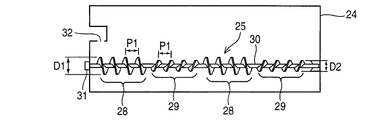
次に第1の実施例の現像剤回収装置について説明する。図1は本実施例の現像剤回収装置の構成を示す長手方向断面図で、現像剤回収装置は、廃トナー回収室24と、この廃トナー回収室24内に設けられた回収スクリュー25を備えている。
回収スクリュー25は軸部30と、この軸部30上に一体成形された第1の螺旋スクリュー28及び第2の螺旋スクリュー29から成り、第1の螺旋スクリュー28及び第2の螺旋スクリュー29は軸方向に交互に複数、本実施例では2カ所ずつ設けられている。
Next, the developer recovery apparatus of the first embodiment will be described. FIG. 1 is a longitudinal sectional view showing the configuration of the developer recovery apparatus of this embodiment. The developer recovery apparatus includes a waste toner recovery chamber 24 and a recovery screw 25 provided in the waste toner recovery chamber 24. ing.
The recovery screw 25 includes a shaft portion 30 and a first spiral screw 28 and a second spiral screw 29 integrally formed on the shaft portion 30, and the first spiral screw 28 and the second spiral screw 29 are shafts. A plurality, alternately two in the present embodiment, are provided in the direction.

この回収スクリュー25の軸部30の両端は廃トナー回収室24の両端で回転自在に軸支されていて、その一端は廃トナー回収室24を貫通して廃トナー回収室24の外部に突出し、その突出部分にギヤ31が取り付けられており、該ギヤ31が図示せぬ駆動手段により回転することで、回収スクリュー25が回転するようになっている。   Both ends of the shaft portion 30 of the recovery screw 25 are rotatably supported at both ends of the waste toner recovery chamber 24, and one end of the recovery screw 25 penetrates the waste toner recovery chamber 24 and protrudes outside the waste toner recovery chamber 24. A gear 31 is attached to the protruding portion, and the recovery screw 25 is rotated when the gear 31 is rotated by a driving means (not shown).

また、第1の螺旋スクリュー28は外径D1、山間のピッチP1で形成されていて、廃トナーを廃トナー回収室24の他端側つまり回収口32と反対側へ搬送するように螺旋(スパイラル)状に形成されており、第2の螺旋スクリュー29は外径D2、山間のピッチP1で形成されていて、第1の螺旋スクリュー28とは逆巻き形成され、廃トナーを廃トナー回収室24の回収口32側へ搬送するように螺旋(スパイラル)状に形成されている。   Further, the first spiral screw 28 is formed with an outer diameter D1 and a pitch P1 between the peaks, and spirals so as to convey the waste toner to the other end side of the waste toner collection chamber 24, that is, the side opposite to the collection port 32. The second spiral screw 29 is formed with an outer diameter D2 and a pitch P1 between the mountains, and is wound in a reverse direction with respect to the first spiral screw 28, and waste toner is collected in the waste toner collecting chamber 24. It is formed in a spiral shape so as to be conveyed to the collection port 32 side.

この第1の螺旋スクリュー28の外径D1は第2の螺旋スクリュー29の外径D2よりも大きい関係にあり、また第1の螺旋スクリュー28の山間のピッチP1は第2の螺旋スクリュー29の山間のピッチP2と等しい関係にあるが、回収スクリュー25全体として廃トナーを廃トナー回収室24の回収口32側から奥側へと搬送可能である。   The outer diameter D1 of the first spiral screw 28 is larger than the outer diameter D2 of the second spiral screw 29, and the pitch P1 between the peaks of the first spiral screw 28 is the pitch between the peaks of the second spiral screw 29. However, the entire collection screw 25 can convey waste toner from the collection port 32 side to the back side of the waste toner collection chamber 24.

図2は上述した構成による第1の実施例の現像剤回収装置の作用を示す説明図で、ここでは説明を分かりやすくするため、回収口32に最も近い最上流の第1の螺旋スクリュー28を28a、これより下流側の第1の螺旋スクリュー28を28b、第1の螺旋スクリュー28aと28baの間の第2の螺旋スクリュー29を29a、第1の螺旋スクリュー28bの下流側の第2の螺旋スクリュー29を29bとする。   FIG. 2 is an explanatory view showing the operation of the developer recovery apparatus of the first embodiment having the above-described configuration. Here, for the sake of easy understanding, the most upstream first spiral screw 28 closest to the recovery port 32 is provided. 28a, the first spiral screw 28 downstream of this, 28b, the second spiral screw 29 between the first spiral screws 28a and 28ba 29a, the second spiral downstream of the first spiral screw 28b The screw 29 is 29b.

図2(a)は回収口32に最も近い最上流の第1の螺旋スクリュー28aと第2の螺旋スクリュー29aにかかる位置まで廃トナー33が回収された状態、図2(b)は第2の螺旋スクリュー29bの下流側の位置まで廃トナー33が回収された状態、図2(c)は廃トナー回収室24がほぼ廃トナー33により満たされた状態を示している。   FIG. 2A shows a state in which the waste toner 33 is collected up to the position on the first spiral screw 28a and the second spiral screw 29a that are closest to the collection port 32, and FIG. FIG. 2C shows a state where the waste toner 33 is collected up to a position downstream of the spiral screw 29 b, and FIG. 2C shows a state where the waste toner collection chamber 24 is almost filled with the waste toner 33.

回収スクリュー25が回転している状態で、上記のように搬送ベルト18により廃トナー収集室26から搬送されてきた廃トナー33が回収口32から廃トナー回収室24内に落とし込まれると、廃トナー33は回収スクリュー25の回収口32に最も近くに位置している第1の螺旋スクリュー28aにより奥側へと搬送され、そして第1の螺旋スクリュー28aの奥側に搬送された廃トナー33は第2の螺旋スクリュー29aにより回収口32側へと戻される。   If the waste toner 33 transported from the waste toner collecting chamber 26 by the transport belt 18 as described above is dropped into the waste toner collecting chamber 24 from the recovery port 32 in the state where the recovery screw 25 is rotating, the waste screw 33 is discarded. The toner 33 is conveyed to the back side by the first spiral screw 28a located closest to the recovery port 32 of the recovery screw 25, and the waste toner 33 conveyed to the back side of the first spiral screw 28a is It is returned to the collection port 32 side by the second spiral screw 29a.

このとき、第1の螺旋スクリュー28aと第2の螺旋スクリュー29aの間で対流が発生し、廃トナー33は図2(a)に示したように第1の螺旋スクリュー28aと第2の螺旋スクリュー29aにかかる位置周辺で丘状に溜まる。
廃トナー33の回収量が増えていくと、第1の螺旋スクリュー28aの方が第2の螺旋スクリュー29bより搬送能力が大きいので廃トナー33は徐々に下流側に搬送され、第2の螺旋スクリュー29aより下流側に搬送された廃トナー33は、第1の螺旋スクリュー28bによりさらに奥側へと搬送される。
At this time, convection occurs between the first spiral screw 28a and the second spiral screw 29a, and the waste toner 33 is transferred to the first spiral screw 28a and the second spiral screw as shown in FIG. It accumulates in a hill around the position of 29a.
As the amount of waste toner 33 collected increases, the first helical screw 28a has a larger conveying capacity than the second helical screw 29b, so that the waste toner 33 is gradually conveyed downstream, and the second helical screw The waste toner 33 conveyed downstream from 29a is further conveyed to the back side by the first spiral screw 28b.

第1の螺旋スクリュー28bの奥側に搬送された廃トナーは第2の螺旋スクリュー29bにより回収口側へと戻されるが、このとき、上流側と同様に第1の螺旋スクリュー28bと第2の螺旋スクリュー29bの間で対流が発生し、そのため廃トナー33は図2(b)に示したように第1の螺旋スクリュー28bと第2の螺旋スクリュー29bにかかる位置周辺で丘状に溜まる。そして回収スクリュー25の回転により廃トナー33はならされ、更に送られて廃トナー33は図2(b)に示したように廃トナー回収室24の奥に達することになる。   The waste toner conveyed to the back side of the first spiral screw 28b is returned to the recovery port side by the second spiral screw 29b. At this time, the first spiral screw 28b and the second spiral screw 28b are returned as in the upstream side. Convection occurs between the spiral screws 29b, and as a result, the waste toner 33 accumulates in a hill shape around the positions of the first spiral screw 28b and the second spiral screw 29b as shown in FIG. Then, the waste toner 33 is smoothed by the rotation of the collection screw 25 and further sent, and the waste toner 33 reaches the back of the waste toner collection chamber 24 as shown in FIG.

その後、更に廃トナー33の回収量が増えていくと、第1の螺旋スクリュー28aと第2の螺旋スクリュー29aの間、及び第1の螺旋スクリュー28bと第2の螺旋スクリュー29bの間にできた丘が上方向横方向に成長していき、廃トナー33はならされて図2(c)に示したように廃トナー回収室24がほぼ廃トナーにより満たされた状態になる。   After that, when the amount of waste toner 33 collected further increased, it was formed between the first spiral screw 28a and the second spiral screw 29a, and between the first spiral screw 28b and the second spiral screw 29b. As the hill grows upward and laterally, the waste toner 33 is smoothed and the waste toner collection chamber 24 is almost filled with waste toner as shown in FIG.

以上説明したように第1の実施例によれば、廃トナー33を廃トナー回収室24の回収口32から奥側に搬送する回収スクリュー25に廃トナー33を奥側に搬送する第1の螺旋スクリュー28と廃トナーを回収口32側に搬送する第2の螺旋スクリュー29を交互に複数配置した構成として、回収スクリュー25が回転したとき廃トナーを奥側に搬送する第1の螺旋スクリュー28と廃トナーを回収口32側に搬送する第2の螺旋スクリュー29により廃トナーは複数の丘ができるように溜まるようにしているため、廃トナー回収室24内全域にわたって廃トナー33がならされ、局所的に大きな山ができることなく回収することが可能となるので、廃トナー33の収容効率が向上するという効果が得られる。   As described above, according to the first embodiment, the first spiral for transporting the waste toner 33 to the back side to the recovery screw 25 for transporting the waste toner 33 from the recovery port 32 of the waste toner recovery chamber 24 to the back side. As a configuration in which a plurality of second spiral screws 29 that alternately convey the screw 28 and waste toner to the collection port 32 are arranged, the first spiral screw 28 that conveys waste toner to the back side when the collection screw 25 rotates, Since the second spiral screw 29 that transports the waste toner to the collection port 32 side accumulates the waste toner so as to form a plurality of hills, the waste toner 33 is leveled over the entire area of the waste toner collection chamber 24 and is locally Therefore, it is possible to collect the waste toner 33 without creating a large mountain, and the effect of improving the waste toner 33 accommodation efficiency can be obtained.

尚、本実施例では、第1の螺旋スクリュー28と第2の螺旋スクリュー29の外径が異なる構成について説明したが、第1の螺旋スクリュー28の巻き数を第2の螺旋スクリュー29の巻き数より多くして長さを長くすれば第1の螺旋スクリュー28と第2の螺旋スクリュー29の外径を同じにしても、同様の作用、効果が得られる。   In addition, although the present Example demonstrated the structure from which the outer diameter of the 1st spiral screw 28 and the 2nd spiral screw 29 differs, the winding number of the 1st spiral screw 28 is set to the winding number of the 2nd spiral screw 29. If the length is increased by increasing the length, even if the outer diameters of the first spiral screw 28 and the second spiral screw 29 are the same, the same action and effect can be obtained.

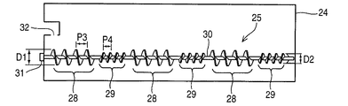
次に第2の実施例について説明する。図7は第2の実施例の現像剤回収装置の構成を示す長手方向断面図で、この第2の実施例は、回収スクリュー25の軸部30に第1の螺旋スクリュー28と第2の螺旋スクリュー29を軸方向に交互に3カ所ずつ一体成形したものであって、ここで第1の螺旋スクリュー28は外径D1、山間のピッチP3で形成されており、第2の螺旋スクリュー29は外径D2、山間のピッチP4で形成されている。   Next, a second embodiment will be described. FIG. 7 is a longitudinal sectional view showing the configuration of the developer recovery apparatus of the second embodiment. In the second embodiment, the first spiral screw 28 and the second spiral are arranged on the shaft portion 30 of the recovery screw 25. The screws 29 are integrally formed alternately at three locations in the axial direction. Here, the first spiral screw 28 is formed with an outer diameter D1 and a pitch P3 between the mountains, and the second spiral screw 29 is an outer portion. It is formed with a diameter D2 and a pitch P4 between mountains.

また、第1の螺旋スクリュー28の外径D1は第2の螺旋スクリュー29の外径D2よりも大きく、かつ第1の螺旋スクリュー28の山間のピッチP3は第2の螺旋スクリュー29の山間のピッチP4よりも大きい関係にあり、回収スクリュー25全体として廃トナーを廃トナー回収室24の回収口32側から奥側へと搬送可能である。
尚、この他の構成は上述した第1の実施例と同様であるので、同一部分には同一の符号を付してその説明を省略する。
The outer diameter D1 of the first spiral screw 28 is larger than the outer diameter D2 of the second spiral screw 29, and the pitch P3 between the peaks of the first spiral screw 28 is the pitch between the peaks of the second spiral screw 29. The waste toner can be transported from the collection port 32 side to the back side of the waste toner collection chamber 24 as a whole in the collection screw 25 because the relationship is larger than P4.
Since the other configuration is the same as that of the first embodiment described above, the same parts are denoted by the same reference numerals and the description thereof is omitted.

図8は上述した構成による第2の実施例の現像剤回収装置の作用を示す説明図で、ここでは説明を分かりやすくするため、回収口32に最も近い最上流の第1の螺旋スクリュー28を28a、これより下流側の第1の螺旋スクリュー28を28b、更に下流側の第1の螺旋スクリュー28を28cとし、また、第1の螺旋スクリュー28aと28bの間の第2の螺旋スクリュー29を29a、第1の螺旋スクリュー28bと28cの間の第2の螺旋スクリュー29を29b、第1の螺旋スクリュー28cの下流側の第2の螺旋スクリュー29を29cとする。   FIG. 8 is an explanatory view showing the operation of the developer recovery apparatus of the second embodiment having the above-described configuration. Here, for the sake of easy understanding, the most upstream first spiral screw 28 closest to the recovery port 32 is provided. 28a, the first helical screw 28 on the downstream side is 28b, the first helical screw 28 on the further downstream side is 28c, and the second helical screw 29 between the first helical screws 28a and 28b is 29a, the second helical screw 29 between the first helical screws 28b and 28c is 29b, and the second helical screw 29 on the downstream side of the first helical screw 28c is 29c.

図8(a)は回収口32に最も近い最上流の第1の螺旋スクリュー28aと第2の螺旋スクリュー29aにかかる位置まで廃トナー33が回収された状態、図8(b)は第1の螺旋スクリュー28bと第2の螺旋スクリュー29bにかかる位置まで廃トナー33が回収された状態、図8(c)は廃トナー回収室24がほぼ廃トナー33により満たされた状態を示している。   FIG. 8A shows a state in which the waste toner 33 has been collected up to the position on the first spiral screw 28a and the second spiral screw 29a that are closest to the collection port 32, and FIG. FIG. 8C shows a state in which the waste toner collection chamber 24 is almost filled with the waste toner 33. FIG. 8C shows a state in which the waste toner 33 is collected up to the position of the spiral screw 28b and the second spiral screw 29b.

回収スクリュー25が回転している状態で、上記のように搬送ベルト18により廃トナー収集室26から搬送されてきた廃トナー33が回収口32から廃トナー回収室24内に落とし込まれると、廃トナー33は回収スクリュー25の回収口32に最も近くに位置している第1の螺旋スクリュー28aにより奥側へと搬送され、そして第1の螺旋スクリュー28aの奥側に搬送された廃トナー33は第2の螺旋スクリュー29aにより回収口32側へと戻される。   If the waste toner 33 transported from the waste toner collecting chamber 26 by the transport belt 18 as described above is dropped into the waste toner collecting chamber 24 from the recovery port 32 in the state where the recovery screw 25 is rotating, the waste screw 33 is discarded. The toner 33 is conveyed to the back side by the first spiral screw 28a located closest to the recovery port 32 of the recovery screw 25, and the waste toner 33 conveyed to the back side of the first spiral screw 28a is It is returned to the collection port 32 side by the second spiral screw 29a.

このとき、第1の螺旋スクリュー28aと第2の螺旋スクリュー29aの間で対流が発生し、廃トナー33は図2(a)に示したように第1の螺旋スクリュー28aと第2の螺旋スクリュー29aにかかる位置周辺で丘状に溜まる。
廃トナー33の回収量が増えていくと、第1の螺旋スクリュー28aの方が第2の螺旋スクリュー29bより搬送能力が大きいので廃トナー33は徐々に下流側に搬送され、第2の螺旋スクリュー29aより下流側に搬送された廃トナー33は、第1の螺旋スクリュー28bによりさらに奥側へと搬送される。
At this time, convection occurs between the first spiral screw 28a and the second spiral screw 29a, and the waste toner 33 is transferred to the first spiral screw 28a and the second spiral screw as shown in FIG. It accumulates in a hill around the position of 29a.
As the amount of waste toner 33 collected increases, the first helical screw 28a has a larger conveying capacity than the second helical screw 29b, so that the waste toner 33 is gradually conveyed downstream, and the second helical screw The waste toner 33 conveyed downstream from 29a is further conveyed to the back side by the first spiral screw 28b.

第1の螺旋スクリュー28bの奥側に搬送された廃トナーは第2の螺旋スクリュー29bにより回収口側へと戻されるが、このとき、上流側と同様に第1の螺旋スクリュー28bと第2の螺旋スクリュー29bの間で対流が発生し、そのため廃トナー33は図8(b)に示したように第1の螺旋スクリュー28bと第2の螺旋スクリュー29bにかかる位置周辺で丘状に溜まる。   The waste toner conveyed to the back side of the first spiral screw 28b is returned to the recovery port side by the second spiral screw 29b. At this time, the first spiral screw 28b and the second spiral screw 28b are returned as in the upstream side. Convection occurs between the spiral screws 29b, and as a result, the waste toner 33 accumulates in a hill-like shape around the positions of the first spiral screw 28b and the second spiral screw 29b as shown in FIG. 8B.

その後、更に廃トナー33の回収量が増えていくと、第1の螺旋スクリュー28aと第2の螺旋スクリュー29aの間、及び第1の螺旋スクリュー28bと第2の螺旋スクリュー29bの間にできた丘が上方向及び横方向に成長していき、廃トナー33はならされて図8(c)に示したように廃トナー回収室24がほぼ廃トナーにより満たされた状態になる。   After that, when the amount of waste toner 33 collected further increased, it was formed between the first spiral screw 28a and the second spiral screw 29a, and between the first spiral screw 28b and the second spiral screw 29b. As the hill grows upward and laterally, the waste toner 33 is smoothed and the waste toner collection chamber 24 is almost filled with the waste toner as shown in FIG. 8C.

以上説明したように第2の実施例によれば、第1の実施例と同様に廃トナー33を廃トナー回収室24の回収口32から奥側に搬送する回収スクリュー25に廃トナーを奥側に搬送する第1の螺旋スクリュー28と廃トナーを回収口32側に搬送する第2の螺旋スクリュー29を交互に複数配置した構成として、回収スクリュー25を回転したとき廃トナーを奥側に搬送する第1の螺旋スクリュー28と廃トナーを回収口32側に搬送する第2の螺旋スクリュー29により廃トナーは複数の丘ができるように溜まるようにしているため、廃トナー回収室24内全域にわたって廃トナーがならされ、局所的に大きな山ができることなく回収することが可能となるので、廃トナーの収容効率が向上するという効果が得られる。しかもこの第2の実施例では、第1の螺旋スクリュー28と第2の螺旋スクリュー29の外径とピッチを変えているため、より均一な廃トナーの搬送を実現できるという効果が得られる。   As described above, according to the second embodiment, as in the first embodiment, the waste toner is transferred to the collection screw 25 that conveys the waste toner 33 from the collection port 32 of the waste toner collection chamber 24 to the back side. In this configuration, a plurality of second spiral screws 29 that alternately convey the first spiral screw 28 that conveys waste toner to the collection port 32 side are disposed, and the waste toner is conveyed to the back side when the collection screw 25 is rotated. Since the first spiral screw 28 and the second spiral screw 29 that transports the waste toner to the collection port 32 side accumulate the waste toner so as to form a plurality of hills, the waste toner is discarded throughout the waste toner collection chamber 24. Since the toner is smoothed and can be collected without causing a large mountain locally, an effect of improving waste toner storage efficiency can be obtained. In addition, in the second embodiment, since the outer diameters and pitches of the first spiral screw 28 and the second spiral screw 29 are changed, an effect of realizing more uniform waste toner conveyance can be obtained.

尚、上述した第2の実施例では、第1の螺旋スクリュー28と第2の螺旋スクリュー29の外径とピッチが異なる構成について説明したが、第1の螺旋スクリュー28のピッチだけ、或いは、ピッチと巻き数を変えても同様の作用、効果が得られ、第1の螺旋スクリュー28と第2の螺旋スクリュー29の外径、ピッチ、巻き数を適宜に変更することで搬送能力の細かい調整が可能となる。   In the second embodiment described above, the configuration in which the outer diameter and the pitch of the first spiral screw 28 and the second spiral screw 29 are different has been described, but only the pitch of the first spiral screw 28 or the pitch. Even if the number of turns is changed, the same action and effect can be obtained, and fine adjustment of the conveying capacity can be achieved by appropriately changing the outer diameter, pitch, and number of turns of the first spiral screw 28 and the second spiral screw 29. It becomes possible.

以上本発明の実施例について説明したが、これに限られるものではない。例えば、上述した各実施例では現像剤回収装置が備えられたトナーカートリッジを例に説明したが、転写ベルトから廃トナーを回収する廃トナー回収ボックスにも適用可能である。
また、上述した各実施例では画像形成装置としてプリンタを用いて説明したが、複写機、FAX、これらを複合させた複合機にも適用可能である。
Although the embodiment of the present invention has been described above, the present invention is not limited to this. For example, in each of the above-described embodiments, the toner cartridge provided with the developer recovery device has been described as an example. However, the present invention can be applied to a waste toner recovery box that recovers waste toner from the transfer belt.
In each of the above-described embodiments, the printer is used as the image forming apparatus. However, the present invention can also be applied to a copier, a FAX, and a complex machine in which these are combined.

1 トナーカートリッジ
2 感光体
3 帯電ローラ
4 現像ローラ
5 供給ローラ
6 現像ブレード
7 トナー貯蔵室
8 クリーニングブレード
9 イメージドラムユニット
10 現像装置
11 媒体収容部
12 トナー供給部
13 第1の搬送スパイラル
14 転写ベルトユニット
15 定着ユニット
16 排出ローラ
17 LEDヘッド
18 搬送ベルト
19 第2の搬送スパイラル
20 トナー収容室
21 廃トナー排出路
22 トナー排出口
23 攪拌バー
24 廃トナー回収室
25 回収スクリュー
26 廃トナー収集室
27 サイドプレート
28 第1の螺旋スクリュー
29 第2の螺旋スクリュー
30 軸部
31 ギヤ
32 回収口
33 廃トナー
100 プリンタ
DESCRIPTION OF SYMBOLS 1 Toner cartridge 2 Photoconductor 3 Charging roller 4 Developing roller 5 Supply roller 6 Developing blade 7 Toner storage chamber 8 Cleaning blade 9 Image drum unit 10 Developing device 11 Medium storage part 12 Toner supply part 13 First conveyance spiral 14 Transfer belt unit 15 Fixing unit 16 Discharging roller 17 LED head 18 Conveying belt 19 Second conveying spiral 20 Toner storage chamber 21 Waste toner discharging path 22 Toner discharging port 23 Stirring bar 24 Waste toner collecting chamber 25 Collecting screw 26 Waste toner collecting chamber 27 Side plate 28 First spiral screw 29 Second spiral screw 30 Shaft portion 31 Gear 32 Collection port 33 Waste toner 100 Printer

Claims (10)

一端側に使用済み現像剤を回収する回収口を有する現像剤回収室内に、前記使用済み現像剤を前記回収口から前記現像剤回収室の他端側へ搬送する第1の螺旋スクリュー部と前記使用済み現像剤を前記回収口側へ搬送する第2の螺旋スクリュー部を同一軸上に交互に配置した現像剤搬送部材を備えたことを特徴とする現像剤回収装置。 A first spiral screw portion for conveying the used developer from the collection port to the other end side of the developer collection chamber in a developer collection chamber having a collection port for collecting the used developer on one end side; A developer collecting apparatus comprising: a developer conveying member in which second spiral screw portions for conveying used developer to the collecting port side are alternately arranged on the same axis. 前記第1の螺旋スクリュー部と前記第2の螺旋スクリュー部は少なくとも2個ずつ設けられていることを特徴とする請求項1に記載の現像剤回収装置。   The developer collecting apparatus according to claim 1, wherein at least two of the first spiral screw portion and the second spiral screw portion are provided. 前記第1の螺旋スクリュー部の長さを前記第2の螺旋スクリュー部の長さより長くしたことを特徴とする請求項1または請求項2に記載の現像剤回収装置。   3. The developer recovery apparatus according to claim 1, wherein a length of the first spiral screw portion is longer than a length of the second spiral screw portion. 4. 前記第1の螺旋スクリュー部の径を前記第2の螺旋スクリュー部の径よりも大きくしたことを特徴とする請求項1乃至請求項3のいずれか1項に記載の現像剤回収装置。   4. The developer recovery apparatus according to claim 1, wherein a diameter of the first spiral screw portion is larger than a diameter of the second spiral screw portion. 5. 前記第1の螺旋スクリュー部のピッチを前記第2の螺旋スクリュー部のピッチよりも大きくしたことを特徴とする請求項1乃至請求項4のいずれか1項に記載の現像剤回収装置。   5. The developer recovery apparatus according to claim 1, wherein a pitch of the first spiral screw portion is larger than a pitch of the second spiral screw portion. 6. 前記第1の螺旋スクリュー部の径とピッチを前記第2の螺旋スクリュー部の径とピッチよりもそれぞれ大きくしたことを特徴とする請求項1乃至請求項5のいずれか1項に記載の現像剤回収装置。   6. The developer according to claim 1, wherein a diameter and a pitch of the first spiral screw portion are larger than a diameter and a pitch of the second spiral screw portion, respectively. Recovery device. 一端側に使用済み現像剤を回収する回収口を有する現像剤回収室内に、前記使用済み現像剤を前記回収口から前記現像剤回収室の他端側へ搬送する第1の螺旋スクリュー部と前記使用済み現像剤を前記回収口側へ搬送する第2の螺旋スクリュー部を同一軸上に交互に配置した現像剤搬送部材を備えた現像剤回収装置を有することを特徴とする現像剤カートリッジ。   A first spiral screw portion for conveying the used developer from the collection port to the other end side of the developer collection chamber in a developer collection chamber having a collection port for collecting the used developer on one end side; A developer cartridge comprising a developer collecting device including a developer conveying member in which second spiral screw portions for conveying used developer to the collection port side are alternately arranged on the same axis. 一端側に使用済み現像剤を回収する回収口を有する現像剤回収室内に、前記使用済み現像剤を前記回収口から前記現像剤回収室の他端側へ搬送する第1の螺旋スクリュー部と前記使用済み現像剤を前記回収口側へ搬送する第2の螺旋スクリュー部を同一軸上に交互に配置した現像剤搬送部材を備える現像剤回収装置を設けた現像剤カートリッジを有することを特徴とする現像装置。   A first spiral screw portion for conveying the used developer from the collection port to the other end side of the developer collection chamber in a developer collection chamber having a collection port for collecting the used developer on one end side; It has a developer cartridge provided with a developer collecting device provided with a developer conveying member in which second spiral screw portions for conveying used developer to the collection port side are alternately arranged on the same axis. Development device. 一端側に使用済み現像剤を回収する回収口を有する現像剤回収室内に、前記使用済み現像剤を前記回収口から前記現像剤回収室の他端側へ搬送する第1の螺旋スクリュー部と前記使用済み現像剤を前記回収口側へ搬送する第2の螺旋スクリュー部を同一軸上に交互に配置した現像剤搬送部材を備える現像剤回収装置を設けたことを特徴とする画像形成装置。   A first spiral screw portion for conveying the used developer from the collection port to the other end side of the developer collection chamber in a developer collection chamber having a collection port for collecting the used developer on one end side; An image forming apparatus, comprising: a developer collecting device provided with a developer conveying member in which second spiral screw portions for conveying used developer to the collecting port side are alternately arranged on the same axis. 一端側に使用済み現像剤を回収する回収口を有する現像剤回収室内に、前記使用済み現像剤を前記回収口から前記現像剤回収室の他端側へ搬送する第1の螺旋スクリュー部と前記使用済み現像剤を前記回収口側へ搬送する第2の螺旋スクリュー部を同一軸上に交互に配置した現像剤搬送部材を備える現像剤回収装置を設けた現像剤カートリッジを有する現像装置を搭載したことを特徴とする画像形成装置。   A first spiral screw portion for conveying the used developer from the collection port to the other end side of the developer collection chamber in a developer collection chamber having a collection port for collecting the used developer on one end side; A developing device having a developer cartridge provided with a developer collecting device provided with a developer conveying member in which second spiral screw portions for conveying used developer to the collecting port side are alternately arranged on the same axis is mounted. An image forming apparatus.
JP2011181730A 2011-08-23 2011-08-23 Developer recovery device, developer cartridge, developing device, and image forming apparatus Pending JP2013044884A (en)

Priority Applications (1)

Application Number Priority Date Filing Date Title
JP2011181730A JP2013044884A (en) 2011-08-23 2011-08-23 Developer recovery device, developer cartridge, developing device, and image forming apparatus

Applications Claiming Priority (1)

Application Number Priority Date Filing Date Title
JP2011181730A JP2013044884A (en) 2011-08-23 2011-08-23 Developer recovery device, developer cartridge, developing device, and image forming apparatus

Publications (2)

Publication Number Publication Date
JP2013044884A true JP2013044884A (en) 2013-03-04
JP2013044884A5 JP2013044884A5 (en) 2014-01-09

Family

ID=48008851

Family Applications (1)

Application Number Title Priority Date Filing Date
JP2011181730A Pending JP2013044884A (en) 2011-08-23 2011-08-23 Developer recovery device, developer cartridge, developing device, and image forming apparatus

Country Status (1)

Country Link
JP (1) JP2013044884A (en)

Cited By (3)

* Cited by examiner, † Cited by third party
Publication number Priority date Publication date Assignee Title
JP2017015747A (en) * 2015-06-26 2017-01-19 ブラザー工業株式会社 Developer storage unit and image forming apparatus
US9678469B2 (en) 2013-06-26 2017-06-13 Canon Kabushiki Kaisha Collected toner container
CN112334841A (en) * 2018-09-10 2021-02-05 惠普发展公司有限责任合伙企业 Waste toner collecting apparatus for increasing waste toner collecting efficiency

Citations (3)

* Cited by examiner, † Cited by third party
Publication number Priority date Publication date Assignee Title
JPH10105012A (en) * 1996-09-30 1998-04-24 Canon Inc Cleaning device and process cartridge
JP2000162858A (en) * 1998-11-25 2000-06-16 Sharp Corp Developer-feeding device and image-forming device
JP2009128754A (en) * 2007-11-27 2009-06-11 Oki Data Corp Developer collecting container, developer cartridge, developing unit, and image forming apparatus

Patent Citations (3)

* Cited by examiner, † Cited by third party
Publication number Priority date Publication date Assignee Title
JPH10105012A (en) * 1996-09-30 1998-04-24 Canon Inc Cleaning device and process cartridge
JP2000162858A (en) * 1998-11-25 2000-06-16 Sharp Corp Developer-feeding device and image-forming device
JP2009128754A (en) * 2007-11-27 2009-06-11 Oki Data Corp Developer collecting container, developer cartridge, developing unit, and image forming apparatus

Cited By (5)

* Cited by examiner, † Cited by third party
Publication number Priority date Publication date Assignee Title
US9678469B2 (en) 2013-06-26 2017-06-13 Canon Kabushiki Kaisha Collected toner container
JP2017015747A (en) * 2015-06-26 2017-01-19 ブラザー工業株式会社 Developer storage unit and image forming apparatus
CN112334841A (en) * 2018-09-10 2021-02-05 惠普发展公司有限责任合伙企业 Waste toner collecting apparatus for increasing waste toner collecting efficiency
EP3850438A4 (en) * 2018-09-10 2022-06-01 Hewlett-Packard Development Company, L.P. Waste toner collecting device for increasing waste toner collecting efficiency
CN112334841B (en) * 2018-09-10 2023-12-01 惠普发展公司有限责任合伙企业 Waste toner collecting apparatus for increasing waste toner collecting efficiency

Similar Documents

Publication Publication Date Title
US8131183B2 (en) Developer collection container, developer cartridge, developing unit and image forming apparatus
JP4953634B2 (en) Developing device and image forming apparatus
JP2006195401A (en) Electrophotographic image forming device and process cartridge
JP5386467B2 (en) Developer collection container and image forming apparatus
JP5649325B2 (en) Developer container, developing device, and image forming apparatus
JP2013044884A (en) Developer recovery device, developer cartridge, developing device, and image forming apparatus
JP6519740B2 (en) Waste developer container, toner cartridge, image forming apparatus
JP5906221B2 (en) Developer transport device and image forming apparatus
US9020411B2 (en) Toner recovery device and image forming apparatus having the toner recovery device
JP2011191408A (en) Developer collecting device and image forming apparatus using the same
JP5858939B2 (en) Developer container, development forming unit, and image forming apparatus
JP2011123384A (en) Cleaning device, charging device, and image forming apparatus
JP5742176B2 (en) Developer conveying device, image forming apparatus
KR101074745B1 (en) Conveyance apparatus and image forming apparatus
JP2014115469A (en) Waste toner recovery device and image forming apparatus
US11314195B2 (en) Waste toner collecting device for increasing waste toner collecting efficiency
JP2007271863A (en) Developing device, process unit using the same, and image forming apparatus
JP2020118886A (en) Belt unit and image forming apparatus
US8923733B2 (en) Developer supplying device and image forming apparatus
JP6598585B2 (en) Collected toner transfer device
JP2011112676A (en) Waste toner collection container and image forming apparatus
JP6701015B2 (en) Conveyor screw and developing device
JP5962023B2 (en) Developing device, image forming apparatus
JP6216292B2 (en) Developing device, image forming unit, and image forming apparatus
JP2024023835A (en) Powder conveyance device and image forming device

Legal Events

Date Code Title Description
A521 Written amendment

Free format text: JAPANESE INTERMEDIATE CODE: A523

Effective date: 20131115

A621 Written request for application examination

Free format text: JAPANESE INTERMEDIATE CODE: A621

Effective date: 20131115

A977 Report on retrieval

Free format text: JAPANESE INTERMEDIATE CODE: A971007

Effective date: 20140813

A131 Notification of reasons for refusal

Free format text: JAPANESE INTERMEDIATE CODE: A131

Effective date: 20140819

A02 Decision of refusal

Free format text: JAPANESE INTERMEDIATE CODE: A02

Effective date: 20141216