JP2013036846A5 - - Google Patents
Download PDFInfo
- Publication number
- JP2013036846A5 JP2013036846A5 JP2011172877A JP2011172877A JP2013036846A5 JP 2013036846 A5 JP2013036846 A5 JP 2013036846A5 JP 2011172877 A JP2011172877 A JP 2011172877A JP 2011172877 A JP2011172877 A JP 2011172877A JP 2013036846 A5 JP2013036846 A5 JP 2013036846A5
- Authority
- JP
- Japan
- Prior art keywords
- ball
- calculating
- center position
- major axis
- imaging
- Prior art date
- Legal status (The legal status is an assumption and is not a legal conclusion. Google has not performed a legal analysis and makes no representation as to the accuracy of the status listed.)
- Granted
Links
Images


Description
以上の課題を解決するべく、本発明に係る撮像装置は、
ローリングシャッター方式の撮像手段と、
前記撮像手段により連続撮像されることによって、ボール像が楕円形に歪んだ状態で含まれる少なくとも2つのフレーム画像を取得する撮像制御手段と、
前記撮像制御手段により取得した前記フレーム画像を、水平ラインに対して長径が傾斜した楕円形の内領域とその内領域に隣接する外領域とを有する楕円分離度フィルターで、フィルタリング処理することによって、前記内領域と前記外領域の画素の分離度を算出する分離度算出手段と、
前記内領域の中心位置、長径、短径及び傾斜角を変更しながら前記分離度算出手段によって算出される分離度が最大となったときの中心位置、長径、短径及び傾斜角を、前記ボール像の中心位置、長径、短径及び傾斜角として推定する推定手段と、
前記推定手段によって推定された少なくとも2つのフレーム画像の前記ボール像の各推定値に基づいて、前記ボールの運動の状態量を算出する状態量算出手段と、
を備える。
In order to solve the above problems, an imaging apparatus according to the present invention provides:
An imaging unit of b over the ring shutter method,
Imaging control means for acquiring at least two frame images included in a state where the ball image is distorted into an elliptical shape by being continuously imaged by the imaging means;
The frame image acquired by the imaging control unit, an ellipse separability filter having an outer region adjacent the inner region and its inner region elliptical major axis is inclined relative to the horizontal line, by filtering, A degree-of-separation calculating means for calculating a degree of separation between pixels in the inner area and the outer area;
Center position of the area, major axis, the center position when the separation degree to be calculated is it is max by the short diameter and inclined angle the separation degree calculation means while changing the major axis, the minor diameter and the inclination angle, the Estimating means for estimating the center position, major axis, minor axis, and inclination angle of the ball image;
State quantity calculating means for calculating a state quantity of the movement of the ball based on each estimated value of the ball image of at least two frame images estimated by the estimating means;
Is provided.
本発明に係る撮像装置は、
ローリングシャッター方式の撮像手段と、
前記撮像手段により撮像されることによって、ボール像が楕円形に歪んだ状態で含まれるフレーム画像を取得する撮像制御手段と、
前記撮像制御手段により取得した前記フレーム画像を、水平ラインに対して長径が傾斜した楕円形の内領域と、その内領域と同心状であってその内領域の外側においてその内領域に隣接する外領域とを有する楕円分離度フィルターで、フィルタリング処理することによって、前記内領域と前記外領域の画素の分離度を算出する分離度算出手段と、
前記内領域の中心位置、長径、短径及び傾斜角を変更しながら前記分離度算出手段によって算出される分離度が最大となったときの中心位置、長径、短径及び傾斜角を、前記ボール像の中心位置、長径、短径及び傾斜角として推定する推定手段と、
前記推定手段によって推定された中心位置、長径、短径及び傾斜角によって規定される楕円と、それに接する水平な二本の接線との交点の位置を算出する第1の交点算出手段と、
前記推定手段によって推定された中心位置を通る水平線と前記楕円との交点を算出する第2の交点算出手段と、
前記第1の交点算出手段及び前記第2の交点算出手段によって算出された交点の位置と、前記撮像手段のローリングシャッターにおける水平ライン間の遅延時間と、前記ボールの実サイズとに基づき、前記ボールの速度を算出する速度算出手段と、
を備える
An imaging apparatus according to the present invention
An imaging unit of b over the ring shutter method,
An imaging control unit that acquires a frame image included in a state where the ball image is distorted into an elliptical shape by being captured by the imaging unit;
The frame image acquired by the imaging control means includes an elliptical inner region whose major axis is inclined with respect to a horizontal line, and an outer region that is concentric with the inner region and adjacent to the inner region outside the inner region. A degree-of-separation degree calculating means for calculating the degree of separation of the pixels in the inner area and the outer area by performing a filtering process with an elliptical degree-of-separation filter having an area;
Center position of the area, major axis, the center position when the separation degree to be calculated is it is max by the short diameter and inclined angle the separation degree calculation means while changing the major axis, the minor diameter and the inclination angle, the Estimating means for estimating the center position, major axis, minor axis, and inclination angle of the ball image;
First intersection calculation means for calculating the position of the intersection of the ellipse defined by the center position, the major axis, the minor axis and the inclination angle estimated by the estimation means, and two horizontal tangents in contact with the ellipse;
Second intersection point calculating means for calculating an intersection point of a horizontal line passing through the center position estimated by the estimating means and the ellipse;
Wherein the position of the intersection calculated by the first intersection calculating means and the second intersection point calculating means, and the delay time between the horizontal lines in the rolling shutter of the imaging means, based on the actual size of the ball, the ball Speed calculating means for calculating the speed of
With
本発明に係るプログラムは、
コンピュータに、
移動するボールがローリングシャッター方式の撮像手段により連続撮像されることによってそのボール像が楕円形に歪んだ状態で含まれる少なくとも2つのフレーム画像を、水平ラインに対して長径が傾斜した楕円形の内領域とその内領域に隣接する外領域とを有する楕円分離度フィルターで、フィルタリング処理することによって、前記内領域と前記外領域の画素の分離度を算出する分離度算出手段、
前記内領域の中心位置、長径、短径及び傾斜角を変更しながら前記分離度算出手段によって算出される分離度が最大となったときの中心位置、長径、短径及び傾斜角を、前記ボール像の中心位置、長径、短径及び傾斜角として推定する推定手段、
前記推定手段によって推定された少なくとも2つのフレーム画像の前記ボール像の各推定値に基づいて、前記ボールの運動の状態量を算出する状態量算出手段、
として機能させる。
The program according to the present invention is:
On the computer,
As the moving ball is continuously imaged by a rolling shutter type imaging means, at least two frame images including the ball image distorted in an elliptical shape are included in an elliptical shape whose major axis is inclined with respect to the horizontal line. A degree-of-separation calculating means for calculating the degree of separation of the pixels in the inner area and the outer area by performing a filtering process with an elliptical separability filter having an area and an outer area adjacent to the inner area;
Center position of the area, major axis, the center position when the separation degree to be calculated is it is max by the short diameter and inclined angle the separation degree calculation means while changing the major axis, the minor diameter and the inclination angle, the Estimating means for estimating the center position, major axis, minor axis and inclination angle of the ball image,
State quantity calculating means for calculating a state quantity of the movement of the ball based on each estimated value of the ball image of at least two frame images estimated by the estimating means;
To function as.
本発明に係るプログラムは、
コンピュータに、
移動するボールがローリングシャッター方式の撮像手段により撮像されることによってそのボール像が楕円形に歪んだ状態で含まれるフレーム画像を、水平ラインに対して長径が傾斜した楕円形の内領域と、その内領域と同心状であってその内領域の外側においてその内領域に隣接する外領域とを有する楕円分離度フィルターで、フィルタリング処理することによって、前記内領域と前記外領域の画素の分離度を算出する分離度算出手段、
前記内領域の中心位置、長径、短径及び傾斜角を変更しながら前記分離度算出手段によって算出される分離度が最大となったときの中心位置、長径、短径及び傾斜角を、前記ボール像の中心位置、長径、短径及び傾斜角として推定する推定手段、
前記推定手段によって推定された中心位置、長径、短径及び傾斜角によって規定される楕円と、それに接する水平な二本の接線との交点の位置を算出する第1の交点算出手段、
前記推定手段によって推定された中心位置を通る水平線と前記楕円との交点を算出する第2の交点算出手段、
前記第1の交点算出手段及び前記第2の交点算出手段によって算出された交点の位置と、前記撮像手段のローリングシャッターにおける水平ライン間の遅延時間と、前記ボールの実サイズとに基づき、前記ボールの速度を算出する速度算出手段、
として機能させる。
The program according to the present invention is:
On the computer,
A frame image that the ball image by moving the ball is captured by the imaging means of the rolling shutter system is contained in a state distorted elliptical, and an inner region of the oval major axis is inclined relative to the horizontal line, that An elliptical separability filter that is concentric with the inner region and has an outer region adjacent to the inner region outside the inner region. A degree-of-separation calculating means for calculating,
Center position of the area, major axis, the center position when the separation degree to be calculated is it is max by the short diameter and inclined angle the separation degree calculation means while changing the major axis, the minor diameter and the inclination angle, the Estimating means for estimating the center position, major axis, minor axis and inclination angle of the ball image,
First intersection calculation means for calculating the position of the intersection of the ellipse defined by the center position, the major axis, the minor axis, and the inclination angle estimated by the estimation unit and two horizontal tangents in contact with the ellipse;
Second intersection calculation means for calculating an intersection of a horizontal line passing through the center position estimated by the estimation means and the ellipse;
Wherein the position of the intersection calculated by the first intersection calculating means and the second intersection point calculating means, and the delay time between the horizontal lines in the rolling shutter of the imaging means, based on the actual size of the ball, the ball Speed calculating means for calculating the speed of
To function as.
ユニット回路4は、電子撮像部3から出力される被写体の光学像に応じたアナログの画像信号が入力され、入力された画像信号を保持するCDSと、その画像信号を増幅するゲイン調整アンプ(AGC)、そのゲイン調整アンプによって増幅された画像信号をデジタルデータの画像に変換するA/D変換器(ADC)等から構成されている。ユニット回路4は、デジタルの画像を画像生成部6に出力する。
画像生成部6によって画像処理された画像がリーダー・ライター10によって記憶部11に記録されるのは、シャッターボタン8aが押下された際である。シャッターボタン8aが押下される前は、画像生成部6によって画像処理された画像がバッファメモリ12に一時格納され、表示部9がバッファメモリ12に一時格納された画像をビデオ信号に変換した後、ライブビュー画像として表示画面に表示する。
The image processed by the
画像処理部7は、画像の各画素の座標に関する演算、画像の各画素の画素値に関する演算、その他の画像処理を行うプロセッサを具備する。画像処理部7は、プログラム13aに従って画像処理を行う。つまり、プログラム13aが、画像処理部7を打撃時フレーム検出手段7a、第1の平滑化手段7b、円形分離度算出手段7c、第1の推定手段7d、平均色算出手段7e、第2の平滑化手段7f、楕円分離度算出手段7g、第2の推定手段7h、ずれ量算出手段7i、ずらし量算出手段7j、歪み補正手段7k、座標変換手段7m、回転角推定手段7n、速度算出手段7p、垂直射出角算出手段7s及びスピン速度算出手段7t、水平射出角算出手段7uとして機能させる。画像処理部7のこれらの機能については後述する。
The
まず、中央制御部14がプログラム13aによって初期位置設定手段14aとして機能させられることによって、その中央制御部14が画像の各画素の位置を表現する直交二次元座標系の中にボールの初期位置(xini,yini)を設定する(ステップS1)。具体的には、ユーザーが方向操作ボタン8cを操作することによってカーソルをライブビュー画像(ライブビュー画像は、電子撮像部3によって撮像されて表示部9に表示されている。)の中のボールに合わせて、中央制御部14がそのカーソルの位置を初期位置(xini,yini)に設定する。又は、ユーザーがライブビュー画像の中のボールの位置においてタッチパネル8dにタッチしたら、中央制御部14がそのタッチ位置を初期位置(xini,yini)に設定することでもよい。又は、中央制御部14が初期位置(xini,yini)を設定した後、ユーザーが撮像装置100を移動させることによって、ライブビュー画像に表示された枠(枠の中心がボールの初期位置(xini,yini)である。)をボールの位置に合わせることでもよい。初期位置(xini,yini)の際には、ユーザーがライブビュー画像の確認を行いやすいようなゲインがユニット回路4に設定されている。なお、後述のように複数のフレームの画像が連続的に撮像された後、最初のフレーム又は最初から幾つか後のフレームの画像が表示部9に表示された際に、ユーザーが方向操作ボタン8cの操作又はタッチパネル8dをタッチすることによって、画像処理部7がカーソルの位置又はタッチ位置をボールの初期位置(xini,yini)に設定してもよい。なお、電子撮像部3のマトリクス状の画素配列のうち水平ライン(水平方向の画素列)が直交二次元座標系のx方向と平行になり、垂直ライン(垂直方向の画素列)が直交二次元座標系のy方向と平行になる。
First, the
次に、中央制御部14がプログラム13aによって撮像制御手段14bとして機能することで、その中央制御部14が連続撮像処理を行う(ステップS2)。具体的には、ユーザーがシャッターボタン8aを押下すると、中央制御部14がユニット回路4及び電子撮像部3の駆動タイミング及びフレームレートFrateを設定し、撮像制御部5がその駆動タイミング及びフレームレートに従って電子撮像部3をローリングシャッター方式で繰り返し動作させることで、電子撮像部3が高速で連続撮像を行う。電子撮像部3のシャッタースピードはできる限り速く、フレームレートFrate はできる限り高いことが好ましい。
Next, when the
なお、連続撮像の前に初期位置(xini、yini)の設定を行わずに、複数の画像が連続的に撮像された後、最初のフレーム又は最初から幾つか後のフレームが表示部9に表示された際に、ユーザーが方向操作ボタン8cによってカーソルをボール像の位置に合わせることによって(又は、ボール像の位置でタッチパネル8dをタッチすることによって)、中央制御部14がカーソルの位置又はタッチ位置をボールの初期位置(xini、yini)に設定してもよい。
It should be noted that the initial position (x ini , y ini ) is not set before continuous imaging, and after the plurality of images are continuously captured, the first frame or some frames after the first are displayed on the
次に、中央制御部14がプログラム13aによって入力制御手段14cとして機能させられることで、その中央制御部14が操作入力部8を通じて入力されたデータをバッファメモリ12等に格納する。具体的には、ユーザーが操作入力部8を操作することで、各種の撮影条件(例えば、ボール202の大きさ、撮像距離(撮像距離とは、撮像方向Dに対して直交するととともに打撃前のボール202を通った物体面から撮像装置100(レンズユニット1や電子撮像部3)までの距離))を入力し、中央制御部14が入力された撮像条件をバッファメモリ12に格納する。
Next, the
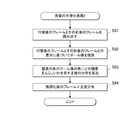
次に、画像処理部7がプログラム13aによって打撃時フレーム検出手段7aとして機能させられることで、画像処理部7は、記憶部11に記録された複数の連続画像の中から、ボール202が打撃された時のフレームを検出する(ステップS3)。ボール202が打撃された時のフレームを検出する処理(ステップS3)について、図7に示すフローチャートを参照して具体的に説明する。
Next, the
図8は、打撃時のフレームの候補を特定する処理(ステップS11)を具体的に示したフローチャートである。図8に示すように、まず、画像処理部7は、中央制御部14によって設定された初期位置(xini、yini)を中心とした矩形状の領域W(図9参照)を設定する(ステップS21)。ここで、図9は領域Wを説明するための図面であり、図9では、ボール202の打撃前のフレームが領域Wとともに示されている。領域Wのサイズ(x方向をwxとし、y方向をwyとする。)はボール像のサイズ以内であることが好ましい。なお、領域Wの形状は矩形でなくてもよい。
FIG. 8 is a flowchart specifically showing a process (step S11) for specifying a frame candidate at the time of hitting. As shown in FIG. 8, first, the
次に、画像処理部7は、記憶部11に記録された複数の連続フレームの中から最初からt番目のフレームとそのNフレーム前のフレームを読み出す(Nは2以上の整数で打撃物が領域Wを通過する時間とフレームレートとに基づく十分に大きい値であることが好ましい)。そして、t番目のフレームの領域WとNフレーム前のt−Nフレームの領域Wとの差分を算出する(ステップS22,S23,S24)。具体的には、次式に示すように、画像処理部7は、t番目のフレームとその前のフレームとの間で同一画素の画素値の差分の絶対値の領域W内における総和を算出する。
Next, the
ここで、tはフレームインデックスであり、ft(x,y)はt番目のフレームの各画素の画素値であり、f t-n (x,y)はt−N番目のフレームの各画素の画素値であり、difW1(t)はt番目のフレームの領域Wとその前のフレームの領域Wとの差分である。 Here, t is a frame index, f t (x, y) is a pixel value of each pixel of the t-th frame, and f tn (x, y) is a pixel of each pixel of the t−N-th frame. DifW1 (t) is a difference between the area W of the t-th frame and the area W of the previous frame.
画像処理部7は、以上のような2つのフレーム間の領域Wの差分difW1(t)の計算をNフレームおきに行う(ステップS25:NO)。そして、以上のような差分difW1(t)の計算が画像処理部7によってNフレームおきに繰り返されて、最後のフレームにまで至ったら(ステップS25:YES)、画像処理部7は、差分difW1(t)が最も大きなフレームを打撃時のフレームの候補に特定する(ステップS26)。以下、このフレームのフレームインデックスをN1とする。なお、差分difW1(t)の計算がNフレームおきに行われたので、計算処理の負担の軽減が図れる。
The
画像処理部7は、差分difW2(t)の計算を1フレームごとに行う。そして、画像処理部7は差分difW2(t)の計算をK回(但し、0<K<N)繰り返し行う(ステップS35:NO)。すなわち、確実にボールが移動していないN1−2N番目のフレームからN1−2N+K番目のフレームの期間の差分difW2(t)を取得し、最大となる差分difW2(t)に基づいて閾値thiを設定する(ステップS36)。例えば、閾値thiは、最大となる差分difW2(t)の2倍の値とする。
The
その後も、画像処理部7は、ftmp(x,y)をテンプレートとしてN1−N番目のフレームからN1番目のフレームまでについての差分difW2(t)の計算を1フレームごとに行う(ステップS37、ステップS38、ステップS39、ステップS40:NO)。N1番目の候補フレームにまで至ったら(ステップS40:YES)、画像処理部7は、差分difW2(t)が閾値thi以上であって且つ最も差分difW2(t)が大きなフレームを打撃時のフレームに特定する(ステップS41)。閾値thi以上としたのは、ボールが打撃される前のフレームや打撃された後で領域W内にボールが無いフレームでのノイズ等による比較的大きな差分difW2(t)を排除するためである。以下、打撃時のフレームのフレームインデックスをN2とする。なお、画像処理部7は、差分difW2(t)が閾値thi以上の最初のフレームを打撃時のフレームとしてもよい。
Thereafter, the
以上のように、ボール202が打撃された時のフレームは、画像処理部7が行う画像処理によって検出される。そのため、ボール202が打撃されたことを検出するトリガセンサが不要となり、撮像装置100の構成がシンプルになる。また、ユニット回路4のISO感度(ゲイン)を上げて、撮像画像にノイズが発生しやすくなっても、差分difW1(t)や差分difW2(t)を利用して打撃時のフレームが検出されるので、ノイズの影響を受けにくい。
As described above, the frame when the ball 202 is hit is detected by the image processing performed by the
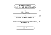
図4に示すように、ボール202が打撃された時のフレームが検出されたら(ステップS3)、画像処理部7はボール202が打撃される前のボール像のサイズ及び中心位置を検出する(ステップS4)。
As shown in FIG. 4, when the frame when the ball 202 is hit is detected (step S3), the
図14は、ボール202が打撃される前のボール像のサイズ及び中心位置を検出する処理(ステップS4)を具体的に示したフローチャートである。図14に示すように、まず、画像処理部7は、ボール202が打撃される前のフレームの中の背景を平滑化(除去)し(ステップS44)、その後、背景が平滑化されたフレームの中のボール像の中心位置及び半径を算出し(ステップS42)、算出した中心位置及び半径を出力する(ステップS43)。
Figure 14 is a flowchart specifically showing before processing it detects the size and the center position of the ball image (step S4) in which the ball 202 is hit. As shown in FIG. 14, first, the
図15は、背景の平滑化処理1(ステップS44)を具体的に示したフローチャートである。背景の平滑化処理1(ステップS44)は、プログラム13aによって第1の平滑化手段7bとして機能させられた画像処理部7によって行われる。
FIG. 15 is a flowchart specifically showing the background smoothing process 1 (step S4 4 ). The background smoothing process 1 (step S4 4 ) is performed by the

分離度ηは、内領域A1と外領域A2の間の変動が領域A1,A2全体の変動に占める割合であって、最大1に正規化された値となっている。分離度ηは、0<η≦1の範囲の値をとる。内領域A1と外領域A2との間で画像特徴量がより大きく分離するにつれて、分離度ηがより大きくなる。内領域A1と外領域A2との間で画像特徴量が最も分離していると、分離度ηが最大値をとる。従って、円形分離度フィルターの半径rを最小値rminから最大値rmaxの範囲内で所定刻み幅(例えば、1〜数画素)で変化させるとともに、円形分離度フィルターの中心位置(x,y)を所定範囲(例えば、初期位置(xini、yini)を中心とした範囲)内で所定刻み幅(例えば、1〜数画素)で変化させて、最大の分離度ηをとる半径r及び中心位置(x,y)をボール像の半径及び中心位置として推定する。
The degree of separation η is the ratio of the fluctuation between the inner area A1 and the outer area A2 to the fluctuation of the entire areas A1 and A2, and is a value normalized to 1 at maximum. The degree of separation η takes a value in the range of 0 <η ≦ 1. As the image feature amount between the inner area A1 and the
具体的には、図16に示すように、画像処理部7は、円形分離度フィルターの中心位置(x,y)及び半径rを初期値(例えば、初期位置(xini、yini)、最小値rmin)に設定する(ステップS61)。次に、画像処理部7は、背景が平滑化された打撃直前のフレーム(図15に示すステップS51の処理で得られたフレーム)を円形分離度フィルターによってフィルタリング処理することによって、内領域A1と外領域A2の各画素の分離度を算出する(ステップS62)。次に、画像処理部7は、画素ごとの分離度の分布に対して補間処理を行うことによって、画素間のサブピクセル単位で分離度を求める(ステップS63)。例えば、画像処理部7は、放物線近似法を利用したサブピクセル推定法によって分離度分布の補間を行う。その後、画像処理部7は、円形分離度フィルターの中心位置(x,y)及び半径rを所定幅だけずらしながら(ステップS65)、同様なフィルタリング処理及び補間処理を繰り返す(ステップS64:NO)。そして、そのような処理の繰り返しが終了したら(ステップS64:YES)、画像処理部7は最大の分離度を得た半径r及び中心位置(x,y)を打撃直前のボール像の半径と中心位置と推定する(ステップS66)。つまり、ステップS66では、画像処理部7は、プログラム13aによって、打撃直前のボール像の半径及び中心位置を推定する第1の推定手段7dとして機能する。
Specifically, as illustrated in FIG. 16, the
図4に示すように、ボール202が打撃される直前のボール像の半径r1及び中心位置(x1,y1)が検出されたら(ステップS4)、画像処理部7がプログラム13aによって平均色算出手段7eとして機能する(ステップS5)。具体的には、画像処理部7は、打撃直前のフレームについて中心位置(x1,y1)付近の複数の画素の平均色(以下、その平均色をaveBcとする。)を算出する(ステップS5)。そして、画像処理部7は、算出した平均色aveBcをバッファメモリ12に記憶しておく。RGB色空間であれば、平均色は、中心位置(x1,y1)付近の複数の画素のR値(赤の輝度値)の平均値と、G値(緑の輝度値)の平均値と、B値(青の輝度値)の平均値とによって表される。
As shown in FIG. 4, when the radius r1 and the center position (x1, y1) of the ball image immediately before the ball 202 is hit are detected (step S4), the
図18は、ボール202が打撃された後のボール像のサイズ、中心位置及び傾斜角を検出する処理(ステップS6)を具体的に示したフローチャートである。図18に示すように、まず、画像処理部7は、打撃後のフレーム(以下、そのフレームインデックスをTとする。)の中の背景を平滑化し(ステップS71)、その後、背景が平滑化されたフレームの中のボール像の中心位置、長径及び短径を算出し(ステップS72)、背景が平滑化されたフレームの中のボール像の水平ライン(x方向)に対する角度を算出する(ステップS73)。
Figure 18 is a flowchart specifically showing processing (step S6) to detect the size of the ball image after the ball 202 is hit, the center position and inclination angle. As shown in FIG. 18, first, the
図19は、背景の平滑化処理2(ステップS71)を具体的に示したフローチャートである。背景の平滑化処理2(ステップS71)は、プログラム13aによって第2の平滑化手段7fとして機能させられた画像処理部7によって行われる。
FIG. 19 is a flowchart specifically showing the background smoothing process 2 (step S71). The background smoothing process 2 (step S71) is performed by the
楕円分離度フィルターは、座標(x,y)に中心を持つ長径L、短径Sの楕円形状の内領域A3と、内領域A3と同心状の領域であって内領域A3の外側において内領域A3に隣接する長径Lmax、短径S max の外領域A4と、から構成される。内領域A3の外縁となる楕円と、外領域A4の外縁となる楕円は相似形である。また、長径L、長径Lmaxがx方向の水平ラインに対して傾斜しており、その傾斜角はθである。この楕円分離度フィルターは、形状こそ上述した円形分離度フィルターと異なるものの、円形分離度フィルターと同様に、内領域A3と外領域A4の画素の分離度を算出するものである。従って、円形分離度フィルターにおける分離度ηの算出式を楕円分離度フィルターにおける分離度の算出式に適用することができる。そのため、楕円分離度フィルターの長径Lを最小値Lminから最大値Lmaxの範囲内で所定刻み幅(例えば、1〜数画素)で変化させ、短径Sを最小値Sminから最大値Smaxの範囲内で所定刻み幅(例えば、1〜数画素)させ、楕円分離度フィルターの中心位置(x,y)を所定範囲内で所定刻み幅(例えば、1〜数画素)で変化させ、更に楕円分離度フィルターの傾斜角θを所定範囲内で所定刻み幅で変化させることで、最大の分離度ηをとる長径L、短径S、中心位置(x、y)及び傾斜角θをボール像の長径、短径、中心位置及び傾斜角として推定する。 The ellipticity separation filter includes an elliptical inner region A3 having a major axis L and a minor axis S centered at coordinates (x, y), and an inner region outside the inner region A3 and concentric with the inner region A3. major axis L max adjacent to A3, and the outer area A4 of the minor axis S max, composed. The ellipse serving as the outer edge of the inner region A3 and the ellipse serving as the outer edge of the outer region A4 are similar. The major axis L and the major axis L max are inclined with respect to the horizontal line in the x direction, and the inclination angle is θ. Although this elliptical separability filter is different in shape from the circular separability filter described above, it calculates the separability of the pixels in the inner region A3 and the outer region A4 in the same manner as the circular separability filter. Therefore, the formula for calculating the degree of separation η in the circular separability filter can be applied to the formula for calculating the degree of separability in the elliptic separability filter. Therefore, the major axis L of the ellipticity separation filter is changed within a range from the minimum value L min to the maximum value L max by a predetermined step size (for example, 1 to several pixels), and the minor axis S is changed from the minimum value S min to the maximum value S. a predetermined step size (for example, 1 to several pixels) within the range of max , and the center position (x, y) of the ellipticity separation filter is changed within a predetermined range with a predetermined step size (for example, 1 to several pixels), Furthermore, the major axis L, minor axis S, the center position (x, y), and the inclination angle θ that take the maximum degree of separation η are changed by changing the inclination angle θ of the ellipticity separation filter within a predetermined range with a predetermined step size. Estimated as the major axis, minor axis, center position and tilt angle of the image.
そして、以上のような分離度算出処理の繰り返しが終了したら、画像処理部7がプログラム13aによって第2の推定手段7hとして機能させられる。第2の推定手段7hとして機能する画像処理部7は、繰り返して算出された分離度のうち最大の分離度を得た長径L、短径S及び中心位置(x,y)を打撃後のボール像の長径、短径及び中心位置と推定する。
以下、以上のようにして推定された長径をL2、短径をS2、中心位置の座標を(x2,y2)とする。推定された長径L2、短径S2及び中心位置(x2,y2)は、画像処理部7及びリーダー・ライター10によって記憶部11に記録される。
When the separation degree calculation process as described above is repeated, the
Hereinafter, the major axis estimated as described above is L2, the minor axis is S2, and the coordinates of the center position are (x2, y2). The estimated major axis L2, minor axis S2, and center position (x2, y2) are recorded in the
そして、以上のような分離度算出処理の繰り返しが終了したら、画像処理部7がプログラム13aによって第2の推定手段7hとして機能させられる。第2の推定手段7hとして機能する画像処理部7は、繰り返して算出された分離度のうち最大の分離度を得た傾斜角θを打撃後のボール像の傾斜角と推定する。以下、このように推定された傾斜角をθ2とする。推定された傾斜角θ2は、画像処理部7及びリーダー・ライター10によって記憶部11に記録される。
When the separation degree calculation process as described above is repeated, the
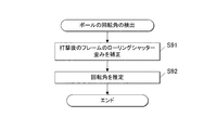
ここで、T番目の打撃後フレームにおけるrsd(T)は補正係数である。x2(T)、x2(T+1)は、図18に示す処理によって算出されたものである。Syは水平ライン数である。補正係数rsd(T)は、ローリングシャッター歪みによって発生したずれ量であって、打撃後のフレームの中の上下に隣り合う水平ライン間がx方向にどの程度ずれているかを示すずれ量である。 Here, rsd (T) in the T-th post-attack frame is a correction coefficient. x2 (T) and x2 (T + 1) are calculated by the process shown in FIG. Sy is the number of horizontal lines. The correction coefficient rsd (T) is a shift amount generated due to rolling shutter distortion, and indicates a shift amount in the x direction between the horizontal lines adjacent to each other vertically in the frame after hitting.
次に、画像処理部7は、ステップS111で生成した三次元球体モデルの表面のボール像と、ステップS114で生成した座標変換後のボール像との差分を算出する(ステップS115)。
Next, the
その後、画像処理部7は、回転行列Irotのピッチ角度θr、ヨー角度θy、ロール角度θpを所定幅だけずらしながら、同様な座標変換及び差分算出を繰り返す(ステップS116:NO)。そして、そのような処理の繰り返しが終了したら(ステップS116:YES)、画像処理部7は最小の差分をとる回転角度θr、θy、θpを1フレーム当たりのボールの回転ピッチ角、回転ヨー角、回転ロール角に推定する(ステップS118)。以下、このように求められたT番目のフレームにおける回転ピッチ角、回転ヨー角、回転ロール角をθr2、θy2、θp2とする。
Thereafter, the
ここで、(xa,ya)は打撃後の所定のフレームにおけるボール像の中心座標、(xb,yb)はその前のフレームにおけるボール像の中心座標、N3はこれらフレームのフレームインデックスの差の絶対値(つまり、これらフレーム間のフレーム数)、Vxはx方向の速度[pixel/sec]、Frateはフレームレート、Vyはy方向の速度[pixel/sec]である。中心座標(xa,ya),(xb,yb)は、図4に示すステップS6の処理で検出されたものである。続いた2つのフレームのボール像の中心座標からボール速度を算出するのであれば、N3の値は1である。打撃後のフレームごとにVx及びVyを算出してもよい。更に、各種撮影条件や実際のボールの直径やボール像の直径等に基づいて、速度Vx,Vyを画像上の速度から実際の速度に換算してもよい。なお、(xb,yb)は、打撃前のフレームにおけるボール像の中心座標(図4に示すステップS4で算出されたもの)とし、N3は打撃時のフレームから、中心座標(xa,ya)を求めた際の打撃後のフレームまでのフレーム数としてもよい。 Here, (x a , y a ) is the center coordinates of the ball image in a predetermined frame after hitting, (x b , y b ) is the center coordinates of the ball image in the previous frame, and N3 is the frame index of these frames The absolute value of the difference (that is, the number of frames between these frames), V x is the velocity in the x direction [pixel / sec], F rate is the frame rate, and V y is the velocity in the y direction [pixel / sec]. Centered coordinate (x a, y a), (x b, y b) are those detected in the process of step S6 shown in FIG. If the ball speed is calculated from the center coordinates of the ball images of the subsequent two frames, the value of N3 is 1. V x and V y may be calculated for each frame after hitting. Furthermore, the speeds V x and V y may be converted from the speed on the image to the actual speed based on various shooting conditions, the actual diameter of the ball, the diameter of the ball image, and the like. Note that (x b , y b ) is the center coordinates of the ball image (calculated in step S4 shown in FIG. 4) in the frame before hitting, and N3 is the center coordinates (x a , It may be the number of frames up to the frame after hitting when obtaining y a ).
ここで、βは水平射出角[rad]、(xa,ya)は打撃後の所定のフレームにおけるボール像の中心座標、(xb,yb)はその前のフレーム(但し、打撃後のフレームである。)におけるボール像の中心座標、(xc,yc)はフレームの中心座標、Sxは垂直ライン数、AHは撮像装置100の撮像手段の水平画角、Laは前記所定のフレームにおいて座標(xa,ya)に中心を有するボール像の長径、Saは前記所定のフレームにおいて座標(xa,ya)に中心を有するボール像の短径、Lbはその前のフレームにおいて座標(xb,yb)に中心を有するボール像の長径、Sbは前記所定のフレームにおいて座標(xb,yb)に中心を有するボール像の短径である。La、Sa、Lb、Sbは、図4に示すステップS6の処理で検出されたものである。
Here, β is the horizontal emission angle [rad], (x a , y a ) is the center coordinate of the ball image in a predetermined frame after hitting, and (x b , y b ) is the previous frame (however, after hitting a frame. center coordinates of the ball image in), (x c, y c ) is the center coordinates of the frame, Sx is the number of vertical lines, a H is a horizontal view angle of the image pickup means of the
図26を参照して、βの算定式について説明する。図26に示すように、撮像装置100の撮像手段(レンズユニット1、電子撮像部3)を基準として三次元座標系uvwを定め、その撮像手段を原点に定める。ここで、u方向は電子撮像部3の水平ラインに平行であり、v方向は電子撮像部3の垂直方向に平行であり、w方向は電子撮像部3の水平方向及び垂直方向に対して直交して、撮像方向Dに対して平行である。打撃後のボール202が位置Aにある時に撮像されたフレームのボール像の中心座標を(xa,ya)とし、それ以前(但し、打撃後である。)にボール202が位置Bにある時に撮像されたフレームのボール像の中心座標を(xb,yb)とする。位置A,Bはボール202の中心位置とし、位置A,Bのuvw座標はそれぞれ(ua,va,w a ),(ub,vb,wb)である。撮像距離Dbcは、撮像装置100の撮像手段(レンズユニット1、電子撮像部3)の光軸に対して直交するとともに打撃前のボール202を通った物体面から、撮像装置100の撮像手段までの距離である。
A formula for calculating β will be described with reference to FIG. As shown in FIG. 26, the three-dimensional coordinate system uvw is defined with reference to the imaging means (
位置Aのボール202と撮像装置100の撮像手段とを結ぶ線が光軸を基準として成す角(水平角θHa、垂直角θVa)や、位置Bの202と撮像装置100の撮像手段とを結ぶ線が光軸を基準として成す角(水平角θHb、垂直角θVb)は、次式で表される。
以上のような速度、垂直射出角、水平射出角、バックスピン速度及びサイドスピン速度の算出後、画像処理部7がボール202の速度、垂直射出角、水平射出角、バックスピン速度及びサイドスピン速度をリーダー・ライター10に出力して、リーダー・ライター10が速度、垂直射出角、水平射出角、バックスピン速度及びサイドスピン速度を記憶部11に記録する。また、算出された速度、垂直射出角、水平射出角、バックスピン速度及びサイドスピン速度を数値や図面等で表す映像が、画像処理部7及び中央制御部14の指令によって表示部9に表示される(ステップS9)。
After calculating the speed, the vertical emission angle, the horizontal emission angle, the back spin speed, and the side spin speed as described above, the
また、プログラム13bは、画像処理部7を平滑化手段7f、楕円分離度算出手段7g、推定手段7h、第1の交点算出手段7v、第2の交点算出手段7w、速度算出手段7x及び垂直射出角算出手段7yとして機能させる。平滑化手段7f、楕円分離度算出手段7g及び推定手段7hは、第1実施形態と同様である。第1の交点算出手段7v、第2の交点算出手段7w、速度算出手段7x及び垂直射出角算出手段7yについては後に詳細に説明する。
The
図28に示されたフローチャートを参照して、プログラム13bに従って中央制御部14及び画像処理部7が行う処理の流れについて説明する。
まず、中央制御部14がプログラム13bによって入力制御手段14gとして機能することで、その中央制御部14が操作入力部8を通じて入力されたデータをバッファメモリ12等に格納する。具体的には、ユーザーが操作入力部8を操作することで、実際のボール202の直径又は半径を入力すると、中央制御部14が入力された直径をバッファメモリ12に格納するか、入力された半径の2倍をバッファメモリ12に格納する(ステップS121)。なお、直径が予め記憶部11又はプログラムメモリ13等に記録されていてもよいし、プログラム13bに組み込まれていてもよい。
With reference to the flowchart shown in FIG. 28, the flow of processing performed by the
First, by the
次に、中央制御部14がプログラム13bによって撮像制御手段14bとして機能することで、その中央制御部14が連続撮像処理を行う。具体的には、ユーザーがシャッターボタン8aを押下すると、中央制御部14が撮像制御部5を通じて電子撮像部3の連続撮像を行わせる(ステップS122)。その際、打撃者がボール202を打撃する。連続撮像処理(ステップS122)は第1実施形態における連続撮像処理(ステップS2)と同様である。なお、打撃前のボール202近傍にトリガセンサが設けられ、打撃者がボール202を打撃したことがトリガセンサによって検出され、そのトリガ信号が中央制御部14に入力されたら、中央制御部14が撮像制御部5を通じて電子撮像部3の連続撮像を行わせてもよい。また、連続撮像ではなく、ボール202の打撃後に高速なシャッタースピードで多重露光して1枚の静止画を撮像するものとしてもよい。
Then, by the
次に、画像処理部7は、打撃後のフレームを記憶部11から読み出す(ステップS123)。
次に、画像処理部7がプログラム13bによって平滑化手段7f、楕円分離度算出手段7g及び推定手段7hとして機能させられ、画像処理部7は読み出したフレームの中のボール像の中心位置、長径、短径及び傾斜角を検出する(ステップS124)。ステップS124における処理は、第1実施形態におけるステップS6における処理と同様である。図29に示すように、ステップS124の処理において、最大の分離度をとる長径、短径、中心位置及び傾斜角をそれぞれL4、S4、(x4,y4)及びθ4とする。また、長径L4、短径S4、中心位置(x4,y4)及び傾斜角θ4から規定される楕円を最適楕円という。なお、ステップS124の処理の前に、第1実施形態の場合と同様に、画像処理部7が打撃時のフレームを検出してもよい(図4のステップS3、図7、図8、図12等参照)。
Next, the
Next, the
まず、画像処理部7がプログラム13bによって第1の交点算出手段7vとして機能させられることによって、画像処理部7は、最適楕円とそれに接する水平な接線H1との交点の座標(x5,y5)を算出するとともに、最適楕円とそれに接するもう一つの水平な接線H2との交点の座標(x6,y6)を算出する。
次に、画像処理部7がプログラム13bによって第2の交点算出手段7wとして機能させられることによって、その画像処理部7は、中心位置(x4,y4)を通る水平線H3と最適楕円との2つの交点の座標(x7,y7)、(x8,y8)を算出する。
First, by the
Next, when the
また、第1、第2の実施形態にあっては、中央制御部14の制御下にて、画像処理部7がプログラム13a,13bを実行することによって各種手段7a〜7n、7p、7s〜7u,7v〜7yの機能を実現した。しかし、これらに限られることではなく、中央制御部14がプログラムメモリ13に格納されたプログラム13a,13bを実行するによってこれらの手段7a〜7n、7p、7s〜7u,7v〜7yの機能を実現してもよい。
In the first and second embodiments, the
Claims (9)
前記撮像手段により連続撮像されることによって、ボール像が楕円形に歪んだ状態で含まれる少なくとも2つのフレーム画像を取得する撮像制御手段と、
前記撮像制御手段により取得した前記フレーム画像を、水平ラインに対して長径が傾斜した楕円形の内領域とその内領域に隣接する外領域とを有する楕円分離度フィルターで、フィルタリング処理することによって、前記内領域と前記外領域の画素の分離度を算出する分離度算出手段と、
前記内領域の中心位置、長径、短径及び傾斜角を変更しながら前記分離度算出手段によって算出される分離度が最大となったときの中心位置、長径、短径及び傾斜角を、前記ボール像の中心位置、長径、短径及び傾斜角として推定する推定手段と、
前記推定手段によって推定された少なくとも2つのフレーム画像の前記ボール像の各推定値に基づいて、前記ボールの運動の状態量を算出する状態量算出手段と、
を備えることを特徴とする撮像装置。 An imaging unit of b over the ring shutter method,
Imaging control means for acquiring at least two frame images included in a state where the ball image is distorted into an elliptical shape by being continuously imaged by the imaging means;
The frame image acquired by the imaging control unit, an ellipse separability filter having an outer region adjacent the inner region and its inner region elliptical major axis is inclined relative to the horizontal line, by filtering, A degree-of-separation calculating means for calculating a degree of separation between pixels in the inner area and the outer area;
Center position of the area, major axis, the center position when the separation degree to be calculated is it is max by the short diameter and inclined angle the separation degree calculation means while changing the major axis, the minor diameter and the inclination angle, the Estimating means for estimating the center position, major axis, minor axis, and inclination angle of the ball image;
State quantity calculating means for calculating a state quantity of the movement of the ball based on each estimated value of the ball image of at least two frame images estimated by the estimating means;
An imaging apparatus comprising:
ことを特徴とする請求項1に記載の撮像装置。The imaging apparatus according to claim 1.
ことを特徴とする請求項1に記載の撮像装置。 The state quantity calculation means calculates a vertical emission angle calculation for calculating an emission angle in the vertical direction of the ball with respect to a horizontal plane from a difference between the center positions of the ball images of at least two frame images estimated by the estimation means. Including means ,
The imaging apparatus according to claim 1 .
ことを特徴とする請求項1に記載の撮像装置。 The state quantity calculating means, the major axis or minor axis of the ball image of at least two frame images have been estimated by the estimating means, the horizontal field angle of the imaging means, and the center coordinates of the frame images, the frame image Horizontal emission angle calculation means for calculating an emission angle in the left-right direction of the ball based on a plane orthogonal to the imaging direction of the imaging means from the number of vertical lines ;
The imaging apparatus according to claim 1 .
ことを特徴とする請求項1から4の何れか一項に記載の撮像装置。 The estimating means, when the separation degree calculated by said separating calculating means while changing the center position, major axis and minor axis in the area in a state where the inclination angle of the area to be constant is it is max the center position of the major axis and the minor axis, center position of the ball image, estimated as the major diameter and minor diameter, its estimated center position, the center position of the region in the major axis and the minor, constant major axis and the minor axis degree of separation is calculated by the separation calculation means the inclination angle when the it is max estimates as the inclination angle of the ball image while changing the inclination angle of the region in a state,
The imaging device according to any one of claims 1 to 4 , wherein
前記ずれ量に基づき、前記フレーム画像のボール像に生じた歪みを、円形に補正する歪み補正手段と、
前記歪み補正手段によって補正されたボール像を、三次元球体モデルの表面に座標変換する座標変換手段と、
前記座標変換手段によって座標変換されたボール像のフレーム画像間における回転角を、推定する回転角推定手段と、
前記回転角推定手段によって推定された回転角とフレームレートとから、前記ボールのスピン速度を算出するスピン速度算出手段と、
を更に備えることを特徴とする請求項1から5の何れか一項に記載の撮像装置。 From said estimating means horizontal difference between the frame image of the estimated center position by the shift amount calculating means for the horizontal shift amount caused by the rolling shutter between the adjacent horizontal lines are calculated,
Distortion correcting means for correcting distortion generated in the ball image of the frame image into a circular shape based on the shift amount;
The ball image corrected by the distortion correction means, a coordinate transformation means for coordinate transformation on the surface of the three-dimensional spherical model,
A rotation angle estimation means the rotation angle, and estimates between the frames images of the coordinate transformed ball image by the coordinate transformation means,
A spin speed calculation means for calculating a spin speed of the ball from the rotation angle and the frame rate estimated by the rotation angle estimation means;
Further comprising an imaging device according to claim 1, any one of 5, wherein the.
前記撮像手段により撮像されることによって、ボール像が楕円形に歪んだ状態で含まれるフレーム画像を取得する撮像制御手段と、
前記撮像制御手段により取得した前記フレーム画像を、水平ラインに対して長径が傾斜した楕円形の内領域と、その内領域と同心状であってその内領域の外側においてその内領域に隣接する外領域とを有する楕円分離度フィルターで、フィルタリング処理することによって、前記内領域と前記外領域の画素の分離度を算出する分離度算出手段と、
前記内領域の中心位置、長径、短径及び傾斜角を変更しながら前記分離度算出手段によって算出される分離度が最大となったときの中心位置、長径、短径及び傾斜角を、前記ボール像の中心位置、長径、短径及び傾斜角として推定する推定手段と、
前記推定手段によって推定された中心位置、長径、短径及び傾斜角によって規定される楕円と、それに接する水平な二本の接線との交点の位置を算出する第1の交点算出手段と、
前記推定手段によって推定された中心位置を通る水平線と前記楕円との交点を算出する第2の交点算出手段と、
前記第1の交点算出手段及び前記第2の交点算出手段によって算出された交点の位置と、前記撮像手段のローリングシャッターにおける水平ライン間の遅延時間と、前記ボールの実サイズとに基づき、前記ボールの速度を算出する速度算出手段と、
を備えることを特徴とする撮像装置。 An imaging unit of b over the ring shutter method,
An imaging control unit that acquires a frame image included in a state where the ball image is distorted into an elliptical shape by being captured by the imaging unit;
The frame image acquired by the imaging control means includes an elliptical inner region whose major axis is inclined with respect to a horizontal line, and an outer region that is concentric with the inner region and adjacent to the inner region outside the inner region. A degree-of-separation degree calculating means for calculating the degree of separation of the pixels in the inner area and the outer area by performing a filtering process with an elliptical degree-of-separation filter having an area;
Center position of the area, major axis, the center position when the separation degree to be calculated is it is max by the short diameter and inclined angle the separation degree calculation means while changing the major axis, the minor diameter and the inclination angle, the Estimating means for estimating the center position, major axis, minor axis, and inclination angle of the ball image;
First intersection calculation means for calculating the position of the intersection of the ellipse defined by the center position, the major axis, the minor axis and the inclination angle estimated by the estimation means, and two horizontal tangents in contact with the ellipse;
Second intersection point calculating means for calculating an intersection point of a horizontal line passing through the center position estimated by the estimating means and the ellipse;
Wherein the position of the intersection calculated by the first intersection calculating means and the second intersection point calculating means, and the delay time between the horizontal lines in the rolling shutter of the imaging means, based on the actual size of the ball, the ball Speed calculating means for calculating the speed of
An imaging apparatus comprising:
移動するボールがローリングシャッター方式の撮像手段により連続撮像されることによってそのボール像が楕円形に歪んだ状態で含まれる少なくとも2つのフレーム画像を、水平ラインに対して長径が傾斜した楕円形の内領域とその内領域に隣接する外領域とを有する楕円分離度フィルターで、フィルタリング処理することによって、前記内領域と前記外領域の画素の分離度を算出する分離度算出手段、
前記内領域の中心位置、長径、短径及び傾斜角を変更しながら前記分離度算出手段によって算出される分離度が最大となったときの中心位置、長径、短径及び傾斜角を、前記ボール像の中心位置、長径、短径及び傾斜角として推定する推定手段、
前記推定手段によって推定された少なくとも2つのフレーム画像の前記ボール像の各推定値に基づいて、前記ボールの運動の状態量を算出する状態量算出手段、
として機能させることを特徴とするプログラム。 On the computer,
As the moving ball is continuously imaged by a rolling shutter type imaging means, at least two frame images including the ball image distorted in an elliptical shape are included in an elliptical shape whose major axis is inclined with respect to the horizontal line. A degree-of-separation calculating means for calculating the degree of separation of the pixels in the inner area and the outer area by performing a filtering process with an elliptical separability filter having an area and an outer area adjacent to the inner area;
Center position of the area, major axis, the center position when the separation degree to be calculated is it is max by the short diameter and inclined angle the separation degree calculation means while changing the major axis, the minor diameter and the inclination angle, the Estimating means for estimating the center position, major axis, minor axis and inclination angle of the ball image,
State quantity calculating means for calculating a state quantity of the movement of the ball based on each estimated value of the ball image of at least two frame images estimated by the estimating means;
A program characterized by functioning as
移動するボールがローリングシャッター方式の撮像手段により撮像されることによってそのボール像が楕円形に歪んだ状態で含まれるフレーム画像を、水平ラインに対して長径が傾斜した楕円形の内領域と、その内領域と同心状であってその内領域の外側においてその内領域に隣接する外領域とを有する楕円分離度フィルターで、フィルタリング処理することによって、前記内領域と前記外領域の画素の分離度を算出する分離度算出手段、
前記内領域の中心位置、長径、短径及び傾斜角を変更しながら前記分離度算出手段によって算出される分離度が最大となったときの中心位置、長径、短径及び傾斜角を、前記ボール像の中心位置、長径、短径及び傾斜角として推定する推定手段、
前記推定手段によって推定された中心位置、長径、短径及び傾斜角によって規定される楕円と、それに接する水平な二本の接線との交点の位置を算出する第1の交点算出手段、
前記推定手段によって推定された中心位置を通る水平線と前記楕円との交点を算出する第2の交点算出手段、
前記第1の交点算出手段及び前記第2の交点算出手段によって算出された交点の位置と、前記撮像手段のローリングシャッターにおける水平ライン間の遅延時間と、前記ボールの実サイズとに基づき、前記ボールの速度を算出する速度算出手段、
として機能させることを特徴とするプログラム。 On the computer,
A frame image that the ball image by moving the ball is captured by the imaging means of the rolling shutter system is contained in a state distorted elliptical, and an inner region of the oval major axis is inclined relative to the horizontal line, that An elliptical separability filter that is concentric with the inner region and has an outer region adjacent to the inner region outside the inner region. A degree-of-separation calculating means for calculating,
Center position of the area, major axis, the center position when the separation degree to be calculated is it is max by the short diameter and inclined angle the separation degree calculation means while changing the major axis, the minor diameter and the inclination angle, the Estimating means for estimating the center position, major axis, minor axis and inclination angle of the ball image,
First intersection calculation means for calculating the position of the intersection of the ellipse defined by the center position, the major axis, the minor axis, and the inclination angle estimated by the estimation unit and two horizontal tangents in contact with the ellipse;
Second intersection calculation means for calculating an intersection of a horizontal line passing through the center position estimated by the estimation means and the ellipse;
Wherein the position of the intersection calculated by the first intersection calculating means and the second intersection point calculating means, and the delay time between the horizontal lines in the rolling shutter of the imaging means, based on the actual size of the ball, the ball Speed calculating means for calculating the speed of
A program characterized by functioning as
Priority Applications (3)
| Application Number | Priority Date | Filing Date | Title |
|---|---|---|---|
| JP2011172877A JP5240328B2 (en) | 2011-08-08 | 2011-08-08 | Imaging apparatus and program |
| US13/565,031 US8704888B2 (en) | 2011-08-08 | 2012-08-02 | Imaging device and image analysis method |
| CN201210277308.1A CN102932591B (en) | 2011-08-08 | 2012-08-06 | Imaging device and image analysis method |
Applications Claiming Priority (1)
| Application Number | Priority Date | Filing Date | Title |
|---|---|---|---|
| JP2011172877A JP5240328B2 (en) | 2011-08-08 | 2011-08-08 | Imaging apparatus and program |
Publications (3)
| Publication Number | Publication Date |
|---|---|
| JP2013036846A JP2013036846A (en) | 2013-02-21 |
| JP2013036846A5 true JP2013036846A5 (en) | 2013-04-04 |
| JP5240328B2 JP5240328B2 (en) | 2013-07-17 |
Family
ID=47647280
Family Applications (1)
| Application Number | Title | Priority Date | Filing Date |
|---|---|---|---|
| JP2011172877A Active JP5240328B2 (en) | 2011-08-08 | 2011-08-08 | Imaging apparatus and program |
Country Status (3)
| Country | Link |
|---|---|
| US (1) | US8704888B2 (en) |
| JP (1) | JP5240328B2 (en) |
| CN (1) | CN102932591B (en) |
Families Citing this family (14)
| Publication number | Priority date | Publication date | Assignee | Title |
|---|---|---|---|---|
| US8976241B1 (en) * | 2012-09-27 | 2015-03-10 | The United States Of America As Represented By The Secretary Of The Navy | Surface deformation image analyzer |
| JP6024547B2 (en) * | 2013-03-22 | 2016-11-16 | カシオ計算機株式会社 | State analysis device, state analysis system, state analysis method and program |
| US10441866B2 (en) | 2013-04-17 | 2019-10-15 | Foxtenn Bgreen, S.L. | Method and system for determining whether a spherical element impacts with a component of a playing field, or arranged on or proximate thereto |
| ES2427489B1 (en) * | 2013-04-17 | 2014-07-08 | Foxtenn Bgreen, S. L. | Method and system to judge whether a spherical element bounces in or out of a few play areas |
| US20170069103A1 (en) * | 2015-09-08 | 2017-03-09 | Microsoft Technology Licensing, Llc | Kinematic quantity measurement from an image |
| CN105721758A (en) * | 2016-04-29 | 2016-06-29 | 广东能飞航空科技发展有限公司 | Ultraviolet-visible light shooting system for UAV |
| JP6645949B2 (en) * | 2016-11-01 | 2020-02-14 | 株式会社ソニー・インタラクティブエンタテインメント | Information processing apparatus, information processing system, and information processing method |
| JP6236600B1 (en) * | 2017-06-02 | 2017-11-29 | 株式会社Gpro | Flight parameter measuring apparatus and flight parameter measuring method |
| CN109001484B (en) * | 2018-04-18 | 2021-04-02 | 广州视源电子科技股份有限公司 | Method and device for detecting rotation speed |
| JP2019211223A (en) * | 2018-05-31 | 2019-12-12 | コニカミノルタ株式会社 | Image processing device, overload detection device, overload detection system and program |
| CN108960172B (en) * | 2018-07-12 | 2021-12-07 | 南京工程学院 | Method for identifying GPR image disease type |
| AU2019383973A1 (en) * | 2018-11-20 | 2021-06-03 | Kama-Tech (Hk) Limited | Handheld laser -based vehicle speed measurement device incorporating an automatic number plate recognition (ANPR) function |
| RU2749492C1 (en) * | 2020-08-21 | 2021-06-11 | Федеральное государственное казенное военное образовательное учреждение высшего образования "Военный учебно-научный центр Военно-воздушных сил "Военно-воздушная академия имени профессора Н.Е. Жуковского и Ю.А. Гагарина" (г. Воронеж) Министерства обороны Российской Федерации | Method for determining center of gravity coordinates of optical image |
| KR20230108724A (en) * | 2022-01-10 | 2023-07-18 | 컨셉 주식회사 | Calculation device, calculation system, calculation method, calculation program |
Family Cites Families (18)
| Publication number | Priority date | Publication date | Assignee | Title |
|---|---|---|---|---|
| US5189711A (en) * | 1989-11-24 | 1993-02-23 | Isaac Weiss | Automatic detection of elliptical shapes |
| JP2810320B2 (en) | 1994-04-18 | 1998-10-15 | 住友ゴム工業株式会社 | Sphere rotation measuring device and measuring method |
| JP3279913B2 (en) * | 1996-03-18 | 2002-04-30 | 株式会社東芝 | Person authentication device, feature point extraction device, and feature point extraction method |
| JP3187748B2 (en) | 1996-10-30 | 2001-07-11 | ブリヂストンスポーツ株式会社 | Golf ball motion measurement method |
| JP2001264016A (en) | 2000-03-15 | 2001-09-26 | Sumitomo Rubber Ind Ltd | Motion-measuring instrument for ball |
| US7292711B2 (en) * | 2002-06-06 | 2007-11-06 | Wintriss Engineering Corporation | Flight parameter measurement system |
| JP3904988B2 (en) * | 2002-06-27 | 2007-04-11 | 株式会社東芝 | Image processing apparatus and method |
| JP2004096504A (en) | 2002-08-30 | 2004-03-25 | Mitsubishi Heavy Ind Ltd | Moving object imaging apparatus |
| JP2005291824A (en) | 2004-03-31 | 2005-10-20 | Yokohama National Univ | Flying behavior measuring apparatus of flying object, and flying behavior measuring method of flying object |
| JP4743048B2 (en) | 2006-08-31 | 2011-08-10 | カシオ計算機株式会社 | Imaging apparatus and program |
| JP4752685B2 (en) | 2006-08-31 | 2011-08-17 | カシオ計算機株式会社 | Imaging apparatus and program |
| JP2008058221A (en) | 2006-09-01 | 2008-03-13 | Kobe Univ | Velocity of high-speed moving body, estimation method of position, estimation program, and estimation system |
| JP4930900B2 (en) * | 2006-09-27 | 2012-05-16 | カシオ計算機株式会社 | Imaging device |
| JP4940968B2 (en) | 2007-01-31 | 2012-05-30 | カシオ計算機株式会社 | Image recording apparatus and program |
| JP4784538B2 (en) * | 2007-03-19 | 2011-10-05 | カシオ計算機株式会社 | Digest image display device, digest image display method and program |
| US8698908B2 (en) * | 2008-02-11 | 2014-04-15 | Nvidia Corporation | Efficient method for reducing noise and blur in a composite still image from a rolling shutter camera |
| JP5067323B2 (en) * | 2008-09-09 | 2012-11-07 | カシオ計算機株式会社 | Imaging apparatus and program |
| JP2010118039A (en) * | 2008-10-16 | 2010-05-27 | Mitsubishi Electric Corp | Mobile object detector |
-
2011
- 2011-08-08 JP JP2011172877A patent/JP5240328B2/en active Active
-
2012
- 2012-08-02 US US13/565,031 patent/US8704888B2/en active Active
- 2012-08-06 CN CN201210277308.1A patent/CN102932591B/en active Active
Similar Documents
| Publication | Publication Date | Title |
|---|---|---|
| JP2013036846A5 (en) | ||
| JP5240328B2 (en) | Imaging apparatus and program | |
| JP6395506B2 (en) | Image processing apparatus and method, program, and imaging apparatus | |
| JP5414405B2 (en) | Image processing apparatus, imaging apparatus, and image processing method | |
| US7834907B2 (en) | Image-taking apparatus and image processing method | |
| US8004570B2 (en) | Image processing apparatus, image-pickup apparatus, and image processing method | |
| JP5234150B2 (en) | Image processing apparatus, image processing method, and program | |
| JP2011029735A5 (en) | ||
| JP6021078B2 (en) | Image processing apparatus and image processing method | |
| JP2017028511A5 (en) | ||
| JP2011066516A (en) | Display apparatus, and control method | |
| JP7197981B2 (en) | Camera, terminal device, camera control method, terminal device control method, and program | |
| KR20090006823A (en) | System for analysis of motion | |
| CN105828003A (en) | Image capturing apparatus and control method thereof | |
| US8643728B2 (en) | Digital photographing device, method of controlling the digital photographing device, and computer-readable storage medium for determining photographing settings based on image object motion | |
| US9781343B2 (en) | Image processing apparatus and method for operating image processing apparatus | |
| US9492748B2 (en) | Video game apparatus, video game controlling program, and video game controlling method | |
| JP5225317B2 (en) | IMAGING DEVICE AND IMAGING DEVICE CONTROL METHOD | |
| JP6325615B2 (en) | Method and apparatus for setting camera focus. | |
| US10841522B2 (en) | Image capturing apparatus, control method therefor, and recording medium | |
| US20170347005A1 (en) | Image pickup apparatus, image pickup method, and program | |
| JP5644364B2 (en) | Image processing apparatus, image processing method, and program | |
| JP2017126964A (en) | Imaging control unit, and imaging apparatus | |
| JP2017174094A (en) | Image processing device, image processing method, and program | |
| WO2019176177A1 (en) | Information processing device, information processing method, and program |