JP2013032619A - Crime-preventing thumb-turn - Google Patents
Crime-preventing thumb-turn Download PDFInfo
- Publication number
- JP2013032619A JP2013032619A JP2011167901A JP2011167901A JP2013032619A JP 2013032619 A JP2013032619 A JP 2013032619A JP 2011167901 A JP2011167901 A JP 2011167901A JP 2011167901 A JP2011167901 A JP 2011167901A JP 2013032619 A JP2013032619 A JP 2013032619A
- Authority
- JP
- Japan
- Prior art keywords
- knob
- thumb
- rotation
- shaft
- button
- Prior art date
- Legal status (The legal status is an assumption and is not a legal conclusion. Google has not performed a legal analysis and makes no representation as to the accuracy of the status listed.)
- Pending
Links
Images


Abstract
Description
本発明は、扉錠の屋内側に設けられたサムターンの摘みの回転を規制することで、扉錠の不正な解錠を阻止するようにした防犯サムターンに関する。 The present invention relates to a crime prevention thumb turn that prevents unauthorized unlocking of a door lock by restricting the rotation of a thumb turn knob provided on the indoor side of the door lock.
住宅の玄関扉や事務所の出入口扉に設けらる扉錠は、屋外側からは合鍵によるシリンダーの操作によって扉錠のデッドボルトを出没作動して施解錠し、屋内側からはサムターンの摘みの回転操作によって施解錠が行えるものである。 Door locks provided on the entrance doors of houses and entrance doors of offices are locked and unlocked by operating the dead bolts of the door locks by operating the cylinder with a key from the outside, and the thumb turn is picked from the indoor side. It can be locked and unlocked by rotating operation.
ところが、近年、扉と枠の隙間や、工具によって扉にあけた小さな穴から針金や棒等を挿入し、回転操作の容易なサムターンの摘みに前記針金や棒等を引っ掛けて該サムターンの摘みを回転させ、不正に扉錠を解錠する「サムターン回し」という犯罪手口が増加している。 However, in recent years, a wire or a bar is inserted through a gap between the door and the frame or a small hole opened in the door with a tool, and the thumb turn is picked by hooking the wire or a bar to the thumb turn that is easy to rotate. There is an increasing criminal trick called “Turn Turn” that rotates and unlocks door locks illegally.
上記不正解錠を阻止するために、例えば、下記特許文献1(特開2005−42498号公報)に開示される防犯サムターンが提案されている。この防犯サムターンは、摘みに一対のボタンと、摘みの回転を規制するストッパーとを設け、ボタンの押圧によってストッパーによる摘みの回転規制を解除して摘みを回転させる一方、屋外側からシリンダーが操作されてサムターンのローターに回転力が入力された場合、ローターの回転によって挟持片を開脚作動して前記ストッパーによる摘みの回転規制を解除し、摘みを回転させるようにしたものである。 In order to prevent the unauthorized unlocking, for example, a crime prevention thumb turn disclosed in Patent Document 1 (Japanese Patent Laid-Open No. 2005-42498) has been proposed. This security thumb turn is provided with a pair of buttons for the knob and a stopper for restricting the rotation of the knob. When the button is pressed, the rotation of the knob is released by rotating the knob while the cylinder is operated from the outside. When a rotational force is input to the thumb-turn rotor, the holding piece is opened by the rotation of the rotor to release the restriction on the knob by the stopper, and the knob is rotated.
しかしながら、上記従来の防犯サムターンは、不正解錠は阻止できる効果はあるが、その構成が複雑で部品点数も多い上、組立作業性も悪く、全体として高価なものになるという問題点があった。
すなわち、摘みの回転を規制する一対のストッパーはボタンとは別途に設けてあり、それぞれを引張りバネで付勢してあること、また、屋外側からシリンダーの操作によって上記回転規制を解除する回転伝達機構は、一対の挟持片を別途に設け、それぞれの挟持片をバネで付勢してコア軸の突起片を挟持し、シリンダーの操作でコア軸を回転して該挟持片を開脚作動させることによって、前記摘みの回転規制を解除するようにしたものである。
However, the conventional crime prevention thumb turn has an effect of preventing unauthorized unlocking, but has a problem in that its configuration is complicated, the number of parts is large, the assembling workability is poor, and the whole is expensive. .
In other words, the pair of stoppers that regulate the rotation of the knob are provided separately from the buttons, and each of them is urged by a tension spring, and the rotation transmission that cancels the rotation regulation by operating the cylinder from the outdoor side. The mechanism is provided with a pair of holding pieces separately, each holding piece is urged by a spring to hold the protruding piece of the core shaft, and the core piece is rotated by operating the cylinder to open the holding piece. Thus, the rotation control of the knob is released.
本発明は上記従来の問題点を解消するためになされたもので、挿入した針金や棒等をサムターンの摘みに引っ掛けて回転させて解錠する不正解錠を阻止できるものであって、構成が簡単で部品点数も少なく、組立作業性にも優れ、しかも良好な操作性が確保でき、耐久性にも優れた防犯サムターンを安価に提供できるようにしたものである。また、一般的なサムターンと同様に、摘みの水平・垂直姿勢で扉錠の施錠・解錠状態が視認可能なものを提供できる。 The present invention has been made to solve the above-described conventional problems, and can prevent unauthorized unlocking by unlocking the inserted wire or bar by hooking on the thumb turn knob and rotating it. It is simple and has a small number of parts, is excellent in assembling workability, can ensure good operability, and can provide a security thumb turn with excellent durability at low cost. In addition, as with a general thumb turn, it is possible to provide a door that can be visually confirmed in the locked / unlocked state of the door lock in a horizontal / vertical posture.
次に、上記の課題を解決するための手段を、実施の形態に対応する図面を参照して説明する。
この発明の請求項1に記載の防犯サムターンは、屋外側からはシリンダー、屋内側からは摘みの操作によって施解錠される扉錠の防犯サムターンにおいて、前記防犯サムターンの外筒の後端部には摘みを回転自在に設け、外筒の前端部にはサム軸を回転自在に設け、前記摘みの軸部を該サム軸に係合し、前記摘みの回転によりサム軸を一体的に回転して摘みの回転を扉錠へ伝達するように設けてあり、前記摘みには一対のボタン部材が保持され、施錠時には該ボタン部材のボタンが摘みから突出すると共に、該ボタン部材に形成した係止部が、前記外筒に形成した係止溝に係合して摘みの回転を規制しすると共に、前記ボタンの押し込みによって上記規制を解除するように設け、一方、前記一対のボタン部材の先端部に形成した制御部を、前記サム軸に形成した制御溝に係合させた回転伝達機構を設け、屋外側からシリンダーの操作により伝達された前記サム軸の回転力により、該回転伝達機構を介して前記摘みの回転の規制を解除するようにしてあることを特徴とする。
Next, means for solving the above problems will be described with reference to the drawings corresponding to the embodiments.
The crime prevention thumb turn according to
この防犯サムターンは、ボタン部材のボタンを押し込みながら回転力が摘みに加えられなければ、摘みによる回転操作が行えず、解錠ができない。これにより、挿入した針金や棒等によって摘みを回転させることによる不正解錠を阻止できる。また、施錠する時には、一般的なサムターンと同様に、ボタン操作に関わらず摘みを回転することができ、施錠することができる。
さらに、屋外側から合鍵によるシリンダーの操作時には扉錠からの回転入力により、回転伝達機構を介してボタン部材による規制が自動解除されて、摘みが回転されるので、良好な操作性が確保される。しかも、摘みを例えば矩形状に形成することで、摘みの水平・垂直姿勢が視認できるので、一般的なサムターンと同様に、屋内側からの扉錠の施解錠状態がが容易に確認できるようになる。
If the rotational force is not applied to the knob while pushing the button of the button member, the crime prevention thumb turn cannot be rotated by the knob and cannot be unlocked. Thereby, unauthorized unlocking by rotating the knob with the inserted wire or rod can be prevented. Further, when locking, the knob can be rotated and locked regardless of the button operation, like a general thumb turn.
Furthermore, when the cylinder is operated with the key from the outdoor side, the control by the button member is automatically released by the rotation input from the door lock, and the knob is rotated, so that the knob is rotated, thus ensuring good operability. . In addition, by forming the knob in a rectangular shape, for example, the horizontal / vertical posture of the knob can be visually confirmed, so that the door lock / unlock state from the indoor side can be easily confirmed as with a general thumb turn. Become.
本発明に係る請求項1に記載の防犯サムターンによれば、摘みの回転を規制する一方、押し込みによって規制を解除する一対のボタン部材を摘みの表裏面に突設し、摘みの回転を扉錠へ伝達する一方、屋外側からのシリンダー操作による扉錠からの回転入力に対してはボタン部材による回転規制を自動解除して摘みを回転可能とする回転伝達機構を、摘みと扉錠との間に設けたので、ボタン部材のボタンを押し込みながら摘みに回転力を加えなければ摘みによる解錠操作は行えず、これにより、挿入した針金や棒等により摘みを回して解錠する不正解錠を阻止でき、防犯性を向上させることができる。 According to the crime prevention thumb turn according to the first aspect of the present invention, a pair of button members that restrict the rotation of the knob while releasing the restriction by pushing are protruded on the front and back surfaces of the knob, and the rotation of the knob is locked to the door. On the other hand, for the rotation input from the door lock by the cylinder operation from the outside side, the rotation transmission mechanism that automatically releases the rotation restriction by the button member and enables the knob to rotate is provided between the knob and the door lock. Therefore, if you do not apply rotational force to the knob while pushing the button of the button member, you cannot perform the unlocking operation with the knob, and this will prevent unauthorized unlocking by turning the knob with an inserted wire or stick etc. It can be prevented and crime prevention can be improved.
本発明の防犯サムターンは、一対のボタン部材はボタンが摘みから突出する方向には圧縮バネで付勢して設け、該ボタン部材に形成した係止部が外筒に設けた係止溝に係合して摘みの回転を規制するので、摘みの回転の規制、規制解錠を確実に行え、しかも構成部材が少なく組立も容易である。さらには、上記回転伝達機構はサム軸の制御溝に係合するボタン部材の制御部とによって構成するようにしたので、防犯サムターン全体の構成部材も少ない。 In the security thumb turn according to the present invention, the pair of button members are provided by being urged by a compression spring in the direction in which the button protrudes from the knob, and the engaging portion formed on the button member is engaged with the engaging groove provided in the outer cylinder. Since the rotation of the knob is regulated in combination, the rotation of the knob and the regulation unlocking can be reliably performed, and the number of constituent members is small and the assembly is easy. Furthermore, since the rotation transmission mechanism is constituted by the control part of the button member engaged with the control groove of the thumb shaft, the number of constituent members of the entire security thumb turn is small.
しかも、一般的なサムターンと同様に、施錠する時はボタンに関わらず摘みを回転して施錠することができると共に、屋外側からの合鍵によるシリンダーの解錠操作時にはボタンによる規制が自動解除されて摘みが回転するので、良好な操作性を確保することができる。さらに、摘みの形状を矩形状とすれば摘みの水平・垂直姿勢が視認できるので、一般的なサムターンと同様に、屋内側から施解錠状態を容易に確認することができる。 In addition, as with a general thumb turn, when locking, the knob can be rotated and locked regardless of the button, and when the cylinder is unlocked from the outdoor side, the restriction by the button is automatically released. Since the knob rotates, good operability can be ensured. Furthermore, since the horizontal and vertical postures of the knob can be visually recognized if the knob is formed in a rectangular shape, the locked / unlocked state can be easily confirmed from the indoor side as in the case of a general thumb turn.
本発明に係る防犯サムターンの実施の形態を図面を参照して以下に説明する。
本発明の防犯サムターンは、屋外側からはシリンダー、屋内側からは摘み2の操作によって施解錠される扉錠の防犯サムターン1において、前記防犯サムターン1の外筒80の後端部には摘み2を回転自在に設け、外筒80の前端部にはサム軸50を回転自在に設け、前記摘み2の軸部2aを該サム軸50に係合し、前記摘み2の回転によりサム軸50を一体的に回転して摘み2の回転を扉錠Lへ伝達するように設けてあり、前記摘み2には一対のボタン部材30、40が保持され、施錠時には該ボタン部材30、40のボタン31、41が摘み2から突出すると共に、該ボタン部材30、40に形成した係止部33、43が、前記外筒80に形成した係止溝73、73に係合して摘み2の回転を規制しすると共に、前記ボタン31、41の押し込みによって上記規制を解除するように設け,一方、前記一対のボタン部材30、40の先端部に形成した制御部34,44を、前記サム軸50に形成した制御溝55、55に係合させた回転伝達機構5を設け、屋外側からシリンダーの操作により伝達された前記サム軸50の回転力により、該回転伝達機構5を介して前記摘みの回転の規制を解除するようにしてあることを特徴とするものである。
詳しくは、以下に説明する実施例を参照するとよい。
Embodiments of a security thumb turn according to the present invention will be described below with reference to the drawings.
The crime prevention thumb turn according to the present invention has a
For details, reference may be made to the embodiments described below.
以下、本発明に係る防犯サムターンの実施例1を図面に基づいて詳細に説明する。
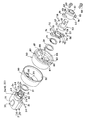
図1は本発明に係る防犯サムターンの施錠状態の横断面図、図4は同上縦断面図、図7は防犯サムターンの分解斜視図、図8は摘みの分解斜視図、図9はボタン部材の分解斜視図、図10はサム軸とサム軸ガイドを後部側(背面側)から見た斜視図である。
Hereinafter,
1 is a cross-sectional view of a security thumb turn according to the present invention, FIG. 4 is a vertical cross-sectional view of the same, FIG. 7 is an exploded perspective view of the security thumb turn, FIG. 8 is an exploded perspective view of a knob, and FIG. FIG. 10 is an exploded perspective view, and FIG. 10 is a perspective view of the thumb shaft and thumb shaft guide as viewed from the rear side (back side).
本実施例による防犯サムターン1が取付けられる扉錠Lは、ハブHの回転により作動機構(図示せず)を介してデッドボルト(図示せず)を出没して施解錠するもので、屋外側から合鍵によるシリンダーの操作によりハブHを回転し、屋内側からは屋内側に設けられた防犯サムターン1の摘み2を回転することによってハブHを回転して施解錠するようになっている。
The door lock L to which the
防犯サムターン1は、以下の構成によって、摘みの回転操作を規制又は規制を解除して回転操作を可能にするように作動される。
扉又は錠には円筒状の外筒80が固定される。この外筒80には、軸線方向の中央部に摘み2を嵌挿して支承する軸受部81が形成されていると共に、該軸受部81より外周の軸線方向に前端側へ突設した隆起部87、87を形成し、この隆起部87、87に軸線方向に貫通する取付穴88、88を形成している。
なお、図1や図7等において、82はサム軸50の鍔部52や固定板70などを嵌装する穴、83は固定板70の取付片74を嵌装する凹部、86は開口部である。
The crime
A cylindrical
In FIGS. 1 and 7, etc., 82 is a hole for fitting the
90は、外筒80の後端部側から該外筒80の外周面を被覆する化粧リングであって、この化粧リング90の後端部の中央には外筒80の軸受部81の先端部を嵌装する穴91が形成されているとともに、前部側に向けて開口部96が形成されている。前記穴91の外周位置に前記外筒80の取付穴88と連通する取付穴92,92が形成されている。
なお、本明細書で、摘み2、サム軸50,軸ガイド60、固定板70、外筒80及び化粧リング90等において、「前端部(前部)」とは屋内側から見て扉方向側をいい、「後端部(後部)」とは屋内側から見て扉より手前側をいう。
In the present specification, in the
前記化粧リング90の開口部96に外筒80を後端部側より嵌入して、外筒80の外周面を化粧リング90で被覆する。そして、、外筒80の取付穴88と化粧リング90の取付穴92とを位置合わせしてから、両取付穴88、92からネジ(図示せず)を挿通して、扉錠Lに直接に固定するか、又はシリンダー(図示せず)に固設した取付柱(図示せず)のネジ穴に螺入して固定する。これにより、外筒80を扉錠又はシリンダーに取付け固定したときに、外筒80と化粧リング90とは一体的に固定される。
The
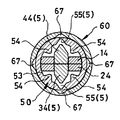
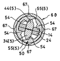
外筒80の内部には、固定板70と軸ガイド60とがネジ68で取付け固定されると共に、サム軸50が回転自在に内設されている。サム軸50は、先端部が断面十字形の入出力軸51を有し、後端部には回転伝達機構5を構成するV字状の制御溝55が上下に形成され、該制御溝55を中心にして左右対称位置に突起部54が4個所に形成されている(図1、図7参照)。なお、このサム軸50には、図3,図7及び図10に示すように鍔部52の直径線上に一対の穴58,58を形成し、この穴58,58にバネ57及びボール56を嵌装している。
Inside the
外筒80には、その後端部から軸受部81に摘み2の軸部2aが挿入されて回転自在に軸支される。2e、2eは座金、2fは抜け留め用のリテーナーである。
なお、摘み2の軸部2aには、水平方向の左右に形成された穴2b、2bにバネ2cとクリック用のボール2dが嵌装され、外筒80の穴82に形成した凹部にボール2dを圧接し、摘み2を施錠状態の水平状態と、垂直状態の解錠状態に安定保持させるようにしている(図1、図2参照)。
The
A
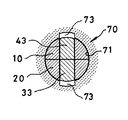
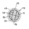
摘み2は、上板10と下板20とに分割され、上下両板10、20の間には揺動軸38を回動中心として、揺動自在とした一対のボタン部材30、40が挟持されている。また、上下両板10、20にはボタン穴11、21が設けられている。ボタン部材30、40の先端部には係止部33、34と制御部34、44が形成され、後端部にはボタン31、41が形成されている。これらのボタン31、41は、上下両板10、20のボタン穴11、21から圧縮バネ等のバネ39により常時突出するように設けられている。なお、圧縮バネ39は、ボタン部材30、40に形成した凹部35、45に設けられる(図4、図5、図9参照)。
The
ボタン部材30、40は、ボタン31、41が摘み2から突出するように付勢されているので、ボタン部材30の先端部は下方へ、ボタン部材40の先端は上方に突出するように付勢され、ボタン部材30、40の係止部33、43は固定板70の係止溝73、73に係合する。従って、摘み2の回転が規制される。また、ボタン31、41を押し込むと、ボタン部材30、40の係止部33、34は固定板70の係止溝73、73の係合が解除され、摘み2の回転が規制が解除される。
なお、図8において、12,13は摘み2を構成する上板10又は下板20に形成された切欠部で、この切欠部12、13にボタン部材30、40の腕部32、42が嵌装される。15、25は前記リテーナー2fを嵌装する溝、16、26はネジ穴、17、27は揺動軸38を支承する軸受部、18はネジ、28は突起部である。
また、図9において、36、46は揺動軸38を嵌挿する揺動軸穴、37,47はガイドである。
Since the
In FIG. 8, 12 and 13 are notches formed in the
In FIG. 9,
一方、外筒80には、その先端部からサム軸50、軸ガイド60、固定板70が嵌装され、固定板70と軸ガイド60はネジ68で外筒80に固定され、サム軸50は回転自在に設けられる。
On the other hand, a
固定板70は、中央に穴71が形成され、その穴71の外周部に鍔部72が設けられ、該鍔部72にサム軸50の後端部が嵌装されてサム軸50が回転自在に設けられる。穴71にはその上下に連設して切欠いた前記係止溝73、73が形成してある。また、鍔部72の上下には取付片74、74が突設してあり、この取付片74、74にネジ68、68の挿通用の取付穴75、75が形成されている。固定板70は、取付片74、74を外筒80に形成した凹部83、83に嵌装し、軸ガイド60と共に、外筒80にネジ68,68により取付け固定される(図4、図7参照)。
The fixing
固定板70の穴71には、外筒80の後端部から挿入された摘み2の軸部2aの先端が挿入され、該軸部2aの先端部から上下に突出するボタン部材30、40の係止部43,33が、前記固定板70の係止溝73、73に係合し、摘み2の回転が規制される。
The tip of the
なお、図2において85はボール2dを出没自在に嵌入する凹部である。図6、図10、図13において53は作動部14、24の係合穴である。図7、図10において、61はサム軸50の軸部51のガイド穴、62は軸受部、63は鍔部、64は上下に延設した取付片、65は取付片64及び取付片74をネジ68により外筒80に螺着するための取付穴、66はサム軸50の鍔部52を嵌装するガイド穴である。
In FIG. 2,
次に、上記構成を有する防犯サムターンの作用を説明する。
図4は施錠状態の縦断面図、図5、図6は図4のC−C断面図、D−D断面図、図11は施錠状態でボタンを押し込んだ状態の縦断面図、図12、図13は図11のC1−C1,D1−D1の断面図である。
Next, the operation of the security thumb turn having the above configuration will be described.
4 is a longitudinal sectional view in a locked state, FIGS. 5 and 6 are CC sectional views and DD sectional views in FIG. 4, FIG. 11 is a longitudinal sectional view in a state where a button is pushed in a locked state, FIG. 13 is a cross-sectional view taken along lines C1-C1 and D1-D1 in FIG.
図4に示す施錠状態において、摘み2は水平方向に位置し、摘み2に内設されたボタン部材30、40はバネ39に付勢され、後端部のボタン31,41は摘み2から突出し、先端部の係止部33、34は、外筒80に固定された固定板70の係止溝73、73に係合し、摘み2の回転が規制されている(図4、図5参照)。
上記の規制を解除するには、図11に示すように、摘み2から突出している上下のボタン31、41を矢印方向に押し込む。
ボタン31、41が押し込まれると、図11、図12に示すように、ボタン部材30、40が揺動してその先端の係止部33、34と固定板70の係止溝73、73との係合が解除されるので、摘み2の回転が可能となる(図11、図12参照)。
In the locked state shown in FIG. 4, the
To release the above restriction, as shown in FIG. 11, the upper and
When the
図14、15は、上記のように、ボタン31、41を押し込んで摘み2を時計方向に約15°回した状態を示すもので、摘み2の先端の作動部14、24がサム軸50の突起部54、54に当接し、さらに摘み2を回せば作動部14、24により突起部54、54が押されてサム軸50も回転し、錠LのハブHが回転して施錠機構が作動されて、錠は解錠される。
なお、解錠操作する場合の摘みの回転角度は一般的に約90°である。
FIGS. 14 and 15 show the state in which the
Note that the rotation angle of the knob in the unlocking operation is generally about 90 °.
図14から明らかなように、施錠状態から摘み2を図11、図12のように、ボタン31、41を押し込んで時計方向に約90°回した場合、外筒80に固定した固定板70のボタン部材30、40の係止部33、43に対応する個所には、係止溝73が無いので、係止部33、43は突出できず、ボタン31、41はその押し込みを解除しても押し込まれたままの状態を保持する。
As is apparent from FIG. 14, when the
摘み2を90°回転して元に戻して錠を施錠すると、ボタン31、41は摘み2から突出し、ボタン部材30、40の係止部33、34は図4、図5のように突出して、固定板70の係止溝73、73に係合するので、摘み2の回転は規制される。
When the
なお、摘み2は施錠状態では水平姿勢に、解錠状態では垂直姿勢になるが、その状態に安定して保持されるようにボール2d、バネ2c、外筒80の凹部85によるクリック装置が設けられている。
The
次に、図4、図5、図6の施錠状態において、屋外側から合鍵によってシリンダー(図示せず)を操作して解錠する場合の説明をする。
シリンダーが操作されると、錠LのハブHが回転し、ハブHに係合する入出力軸51を介して防犯サムターン1のサム軸50に回転力が入力される。
Next, in the locked state of FIG. 4, FIG. 5, FIG. 6, the case where the cylinder (not shown) is operated and unlocked from the outdoor side with a key is described.
When the cylinder is operated, the hub H of the lock L rotates, and a rotational force is input to the
例えば、図6の状態からサム軸50に時計方向への回転力を入力すると、サム軸50の後端部に形成されたV字状の制御溝55、55に係合しているボタン部材30、40の先端のV字状の制御部34、44の斜面部が上記制御溝55、55の斜面部に押され、図18に示すように、制御部34は上方に、制御部44は下方に移動し、図17に示すように、ボタン部材30、40の係止部33、43と固定板70の係止溝73、73との係合が解除される。
従って、ボタン部材30、40のボタン31、41を押し込んだ場合と同様に、摘み2の回転の規制が解除され、摘み2の回転が可能となる(図16〜図18参照)。
For example, when a clockwise rotational force is input to the
Therefore, similarly to the case where the
上記のサム軸50の制御溝55、55と、それに係合するボタン部材30、40の制御部34、44が、本発明の防犯サムターン1の回転伝達機構5を構成する。
なお、前記摘み2と同様に、サム軸50に対しても、その施錠状態位置と解錠状態位置に安定して保持されるように、ボール56、56とバネ57、57及び軸ガイド60に形成した凹部67、67とによるクリック装置が設けられている(図1、図7参照)。
The
As with the
摘み2が回転可能となると、サム軸50も回転可能となるので、そのまま時計方向に約90°回すと扉錠は解錠される。なお、図19,図20は、前記の回転回転伝達機構5により摘み2が回転可能となった状態から、サム軸50を時計方向に約15°回転した状態、すなわち解錠操作の初期の状態を示す。
When the
上記の通り、屋外側からシリンダーを操作して扉錠LのハブHによる回転力の入力により回転伝達機構5を介してサム軸50を回転して解錠した場合も、前記のように屋内側からボタン31、41を押し込んで、摘み2を回転してサム軸50を回転して解錠した場合と同様に、摘み2はボタン31、41が自動的に押し込まれた状態で90°回転し、その解錠状態で保持される。
As described above, even when the cylinder is operated from the outdoor side and the
なお、解錠状態において、屋外側から合鍵によってシリンダーが操作されると、錠LのハブHが回転され、ハブHに係合する入出力軸51を介してサム軸50が回転されるが、解錠状態ではボタン部材30、40の係止部34、44は係止溝73、73に係合しておらず、摘み2の回転は規制されていない。従って、サム軸50の突起部54によって摘み2の作動部14、24が押されて摘み2が回転し、図4〜図6に示す元の施錠状態となる。
In the unlocked state, when the cylinder is operated with the key from the outdoor side, the hub H of the lock L is rotated and the
この防犯サムターン1によれば、ボタン部材30、40を押し込みながらの回転力が摘み2に加えられなければ、特に、一対のボタン31、41をそれぞれ押し込んだ状態で摘み、回転操作をしなければ、摘み2による解錠操作が行えず、これにより、挿入した針金や棒等を摘みに引っ掛けるなどして、摘み2を回転することによる不正解錠が阻止される。また、一般的なサムターンと同様に、摘み2を摘んで回転操作が行え、施錠時にボタン操作に関わらず施錠が行えると共に、屋外側からのシリンダーの操作時には、回転伝達機構5によりボタン部材30、40による回転規制が自動解除されて摘み2が回転されるので、良好な操作性が確保される。更には、摘み2の水平・垂直姿勢が視認可能となるので、一般的なサムターンと同様に、屋内側からの施錠・解錠状態が容易に確認できるようになる。
According to the
更に、この防犯サムターン1では、摘み2の回転を規制する係止部は、係止部材を別途に設けることなく、ボタン部材30、40に係止部33、43を設け、該係止部33、43を外筒80に固定した固定板70の係止溝73、73に係合させてボタン部材30、40により直接摘み2の回転を規制するようにしてあるので、構成部材も少なく、係止部の係合状態は安定しており、強固な規制状態を得ることができる。
しかも、該回転規制の解除もボタン部材30、40の押し込みにより、直接的に行うので回転の規制を確実に解除することができる。
Furthermore, in this
Moreover, since the rotation restriction is released directly by pressing the
また、屋外側からシリンダーの操作による扉錠からの回転入力により、摘み2の回転規制を解除する回転伝達機構5は、サム軸50の制御溝55、55と、それに係合するボタン部材30、40の制御部34、44とにより構成したので、別途に規制解除部材等を設ける必要もないので構成部材が少ない。しかも、該回転伝達機構5は上記サム軸50の鍔部52内部に効率的に設けたので大型化することなく、全体としてコンパクトとな防犯サムターンを提供できる。
Further, the
上記の通り、この防犯サムターン1は、その構成部材が少なくコンパクトであることに加え、前記一対のボタン部材30、40を付勢するバネは圧縮バネであること等の点から、組立し易く全体として安価なものを提供できる。
As described above, the
なお、上記実施例では、摘み2の形状を略矩形状に形成した例について述べたが、これに限ることはなく、矩形状以外の形状、例えば楕円状に中途部分が膨出している形状のものや、あるいは錐形状のものでもよい。 In addition, although the example which formed the shape of the knob | pick 2 in the substantially rectangular shape was described in the said Example, it is not restricted to this, For example, the shape where the middle part swells into an elliptical shape, for example, an ellipse The thing of a thing or a cone shape may be sufficient.
1 防犯サムターン
2 摘み
2a 軸部
5 回転伝達機構
10 上板
12 軸部
20 下板
22 軸部
30 ボタン部材
31 ボタン
33 係止部
34 制御部(回転伝達機構)
40 ボタン部材
41 ボタン
43 係止部
44 制御部(回転伝達機構)
50 サム軸
51 入出力軸
52 鍔部
54 突起部
55 制御部(回転伝達機構)
60 軸ガイド
70 固定板
73 係止溝
80 外筒
90 化粧リング
L 扉錠
H ハブ
DESCRIPTION OF
40
50 Thumb shaft 51 I /
60
Claims (1)
前記防犯サムターンの外筒の後端部には摘みを回転自在に設け、外筒の前端部にはサム軸を回転自在に設け、前記摘みの軸部を該サム軸に係合し、前記摘みの回転によりサム軸を一体的に回転して摘みの回転を扉錠へ伝達するように設けてあり、
前記摘みには一対のボタン部材が保持され、施錠時には該ボタン部材のボタンが摘みから突出すると共に、該ボタン部材に形成した係止部が、前記外筒に形成した係止溝に係合して摘みの回転を規制すると共に、前記ボタンの押し込みによって上記規制を解除するように設け、
一方、前記一対のボタン部材の先端部に形成した制御部を、前記サム軸に形成した制御溝に係合させた回転伝達機構を設け、屋外側からシリンダーの操作により伝達された前記サム軸の回転力により、該回転伝達機構を介して前記摘みの回転の規制を解除するようにしてあることを特徴とする防犯サムターン。 In the security thumb turn of the door lock that is locked and unlocked by the operation of the cylinder from the outdoor side and the knob from the indoor side,
A knob is rotatably provided at a rear end portion of the outer cylinder of the crime prevention thumb turn, a thumb shaft is rotatably provided at a front end portion of the outer cylinder, and a shaft portion of the knob is engaged with the thumb shaft. The rotation of the thumb shaft is integrally rotated to transmit the rotation of the knob to the door lock.
A pair of button members are held in the knob, and the buttons of the button members protrude from the knob when locked, and a locking portion formed on the button member engages with a locking groove formed in the outer cylinder. To restrict the rotation of the knob and to release the restriction by pressing the button,
On the other hand, a rotation transmission mechanism is provided in which a control part formed at the tip part of the pair of button members is engaged with a control groove formed in the thumb shaft, and the thumb shaft transmitted from the outdoor side by the operation of the cylinder is provided. A crime prevention thumb turn characterized in that the restriction of the rotation of the knob is released via the rotation transmission mechanism by a rotational force.
Priority Applications (1)
| Application Number | Priority Date | Filing Date | Title |
|---|---|---|---|
| JP2011167901A JP2013032619A (en) | 2011-07-31 | 2011-07-31 | Crime-preventing thumb-turn |
Applications Claiming Priority (1)
| Application Number | Priority Date | Filing Date | Title |
|---|---|---|---|
| JP2011167901A JP2013032619A (en) | 2011-07-31 | 2011-07-31 | Crime-preventing thumb-turn |
Publications (2)
| Publication Number | Publication Date |
|---|---|
| JP2013032619A true JP2013032619A (en) | 2013-02-14 |
| JP2013032619A5 JP2013032619A5 (en) | 2014-09-11 |
Family
ID=47788689
Family Applications (1)
| Application Number | Title | Priority Date | Filing Date |
|---|---|---|---|
| JP2011167901A Pending JP2013032619A (en) | 2011-07-31 | 2011-07-31 | Crime-preventing thumb-turn |
Country Status (1)
| Country | Link |
|---|---|
| JP (1) | JP2013032619A (en) |
Cited By (1)
| Publication number | Priority date | Publication date | Assignee | Title |
|---|---|---|---|---|
| JP2020139335A (en) * | 2019-02-28 | 2020-09-03 | 株式会社シブタニ | Crime prevention thumb-turn |
Citations (1)
| Publication number | Priority date | Publication date | Assignee | Title |
|---|---|---|---|---|
| JP2007291808A (en) * | 2006-04-27 | 2007-11-08 | Alpha Corp | Thumb-turn device |
-
2011
- 2011-07-31 JP JP2011167901A patent/JP2013032619A/en active Pending
Patent Citations (1)
| Publication number | Priority date | Publication date | Assignee | Title |
|---|---|---|---|---|
| JP2007291808A (en) * | 2006-04-27 | 2007-11-08 | Alpha Corp | Thumb-turn device |
Cited By (1)
| Publication number | Priority date | Publication date | Assignee | Title |
|---|---|---|---|---|
| JP2020139335A (en) * | 2019-02-28 | 2020-09-03 | 株式会社シブタニ | Crime prevention thumb-turn |
Similar Documents
| Publication | Publication Date | Title |
|---|---|---|
| US5010749A (en) | Locking device for an auxiliary lock | |
| US8584495B2 (en) | Exchangeable cylinder lock assembly | |
| KR20180022363A (en) | Digital Door Rock | |
| KR101962783B1 (en) | Inner Multi - Function Handle of Digital Doorlock | |
| KR101533194B1 (en) | Door latch assembly | |
| KR20060133938A (en) | Lock button for door lock of lever type | |
| KR101990918B1 (en) | Slide type interlocking door motis | |
| JP2022519427A (en) | Lock assembly | |
| KR200447937Y1 (en) | Inside handle having means for preventing dead bolt from forced opening | |
| KR100674684B1 (en) | Electronic door lock | |
| JP2013032619A (en) | Crime-preventing thumb-turn | |
| US10480212B2 (en) | Window/door securing device | |
| KR101383289B1 (en) | Inner forced locking assembly of push-pull doorlock | |
| KR20140136718A (en) | Tilt type doorlock | |
| JP4413550B2 (en) | Security thumb turn unit | |
| KR102336019B1 (en) | Door handle device having multi-directional open-close operation function | |
| JP2016061130A (en) | Furniture door lock device | |
| KR20120011545A (en) | Tubular Lock | |
| JP4292014B2 (en) | Thumb turn | |
| JP2014012949A (en) | Sliding door lock | |
| KR101440528B1 (en) | Multi lock device for multi latch | |
| KR101962436B1 (en) | Rotation assembly for mortise having means for clutch | |
| JP4460425B2 (en) | Security thumb turn | |
| US20160281398A1 (en) | Security latch for a swing bar door guard | |
| JP4508758B2 (en) | Button lock |
Legal Events
| Date | Code | Title | Description |
|---|---|---|---|
| A521 | Written amendment |
Free format text: JAPANESE INTERMEDIATE CODE: A523 Effective date: 20140725 |
|
| A621 | Written request for application examination |
Free format text: JAPANESE INTERMEDIATE CODE: A621 Effective date: 20140725 |
|
| A977 | Report on retrieval |
Free format text: JAPANESE INTERMEDIATE CODE: A971007 Effective date: 20150630 |
|
| A131 | Notification of reasons for refusal |
Free format text: JAPANESE INTERMEDIATE CODE: A131 Effective date: 20150728 |
|
| A02 | Decision of refusal |
Free format text: JAPANESE INTERMEDIATE CODE: A02 Effective date: 20151201 |