JP2013019366A - Lubrication structure of piston slide part - Google Patents
Lubrication structure of piston slide part Download PDFInfo
- Publication number
- JP2013019366A JP2013019366A JP2011154431A JP2011154431A JP2013019366A JP 2013019366 A JP2013019366 A JP 2013019366A JP 2011154431 A JP2011154431 A JP 2011154431A JP 2011154431 A JP2011154431 A JP 2011154431A JP 2013019366 A JP2013019366 A JP 2013019366A
- Authority
- JP
- Japan
- Prior art keywords
- piston
- coating
- cylinder liner
- sliding
- slide
- Prior art date
- Legal status (The legal status is an assumption and is not a legal conclusion. Google has not performed a legal analysis and makes no representation as to the accuracy of the status listed.)
- Granted
Links
- 238000005461 lubrication Methods 0.000 title claims abstract description 30
- 239000011248 coating agent Substances 0.000 claims abstract description 107
- 238000000576 coating method Methods 0.000 claims abstract description 107
- 230000002093 peripheral effect Effects 0.000 claims abstract description 9
- 239000010687 lubricating oil Substances 0.000 claims description 10
- 230000001050 lubricating effect Effects 0.000 claims description 7
- 239000012530 fluid Substances 0.000 abstract description 8
- 239000003921 oil Substances 0.000 description 15
- 230000007423 decrease Effects 0.000 description 7
- 229910052751 metal Inorganic materials 0.000 description 6
- 239000002184 metal Substances 0.000 description 6
- 230000002411 adverse Effects 0.000 description 3
- 238000010586 diagram Methods 0.000 description 3
- 230000000694 effects Effects 0.000 description 2
- 229910000831 Steel Inorganic materials 0.000 description 1
- 229910052782 aluminium Inorganic materials 0.000 description 1
- XAGFODPZIPBFFR-UHFFFAOYSA-N aluminium Chemical compound [Al] XAGFODPZIPBFFR-UHFFFAOYSA-N 0.000 description 1
- 238000004880 explosion Methods 0.000 description 1
- 239000000446 fuel Substances 0.000 description 1
- 230000001771 impaired effect Effects 0.000 description 1
- 230000004048 modification Effects 0.000 description 1
- 238000012986 modification Methods 0.000 description 1
- 239000010959 steel Substances 0.000 description 1
- 230000003746 surface roughness Effects 0.000 description 1
Images


Abstract
Description
本発明は、ピストン摺動部の潤滑構造に関するものである。 The present invention relates to a lubricating structure for a piston sliding portion.
図3に示す如く、自動車等における一般的なエンジンでは、シリンダ1内に収容されたピストン2がピストンピン3を介しコンロッド4の小端部4aにより揺動自在に支持されており、該コンロッド4の大端部4bがクランクピン5を介しクランクシャフト6と連結されている。
As shown in FIG. 3, in a general engine in an automobile or the like, a
そして、クランクピン5はクランクアーム6aによりクランクシャフト6の中心からずらした位置に支持されており、クランクピン5がクランクシャフト6の中心回りに円軌道(図3中の一点鎖線を参照)を描いて移動するようになっているので、コンロッド4がピストンピン3を中心に揺動しつつピストン2がシリンダ1内を昇降することになる。
The
一般的に、ピストン2がアルミ製である場合には、スチール製のシリンダライナ1aに対する熱膨張差が大きくなるため、ピストン2側が大きく熱膨張して焼付きを起こすような事態を未然に回避し得るようピストンクリアランスを多く確保する必要があるが、ピストンクリアランスを多く確保してしまうと、ピストンスラップ時に打音が生じてしまうという不具合が生じる。
In general, when the
このため、従来においては、ピストン2のスカート7(ピストン2のピストンリング装着部より下の部分)の外周面に耐焼付き性及び低摩擦特性を有する低摩擦コーティングを施してピストンクリアランスを詰め、これによりピストンスラップ時の打音低減とピストン2の摩擦低減を図るようにしている。
For this reason, conventionally, a low friction coating having seizure resistance and low friction characteristics is applied to the outer peripheral surface of the
ただし、爆発圧力Aにより下方に押し下げられるピストン2は、コンロッド4の傾斜によりピストン2の図中左側が強くシリンダ1の内壁に押し付けられ、このような側圧を受けるスラスト側において、金属接触が発生する混合潤滑の状態が支配的となり、反スラスト側では、油膜を挟んで摩擦面同士が離れて滑る流体潤滑の状態が支配的となるが、流体潤滑が支配的な反スラスト側にまで全域に低摩擦コーティングを施してしまうことで摺動抵抗が増し、これにより燃費の更なる向上を図り得る余地が損なわれているという事実を見い出すに到った。
However, the
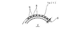
そこで、本発明者は、図4及び図5に示す如く、ピストン2のスカート7における反スラスト側の外周面に、前記ピストン2の摺動方向に向かって延びる縞模様を成すように低摩擦コーティングを施し、そのコーティング部8の相互間に前記ピストン2の摺動方向に潤滑油を逃がす非コーティング部9を残す一方、ピストン2のスカート7におけるスラスト側の外周面全域に低摩擦コーティングを施した構成を創案し、これを下記の特許文献1として既に出願している。
Therefore, as shown in FIGS. 4 and 5, the present inventor has a low friction coating so that a striped pattern extending in the sliding direction of the
このようにすれば、コーティング部8と非コーティング部9との境界にコーティング厚さ分のギャップg(図5参照)が生じ、実質的なシリンダライナ1a側との潤滑面が各コーティング部8の存在する領域だけに限定され、これによりピストン2のスカート7における潤滑面積が低減されて摩擦力が大幅に減少することになる。
In this way, a gap g (see FIG. 5) corresponding to the coating thickness is generated at the boundary between the coating portion 8 and the
即ち、各コーティング部8の相互間に残る非コーティング部9は、ピストン2の摺動方向に開放されていて潤滑油を自由に逃がし得るようになっているため、各非コーティング部9では、流体潤滑の状態にすらならず、潤滑油の粘度も殆ど影響しない非常に摩擦抵抗の少ない状態となるため、実質的なシリンダライナ1a側との潤滑面は、各コーティング部8の存在する領域だけに限定されることになる。
That is, the
しかも、ピストン2のスカート7における反スラスト側では、各コーティング部8とシリンダライナ1aとの間が、油膜を挟んで摩擦面同士が離れて滑っている状態の流体潤滑の状態となるが、各コーティング部8の存在する領域では、ピストンクリアランスが詰まってピストン2の摺動時における油膜厚さが薄くなり、これにより摩擦係数が小さく抑えられて摩擦力がより少なくなる。
Moreover, on the anti-thrust side of the
即ち、図6に縦軸を摩擦係数とし横軸を油膜厚さとしたストライベック線図で示す通り、流体潤滑の領域では、油膜厚さが薄くなるほど摩擦係数μが小さくなるため、各コーティング部8の存在によりピストンクリアランスが詰まって油膜厚さが薄くなれば、その摩擦係数μが小さくなって摩擦力が少なくなる。 That is, as shown in the Stribeck diagram in FIG. 6 where the vertical axis represents the friction coefficient and the horizontal axis represents the oil film thickness, the friction coefficient μ decreases as the oil film thickness decreases in the fluid lubrication region. If the piston clearance becomes clogged due to the presence of oil and the oil film thickness becomes thin, the friction coefficient μ decreases and the frictional force decreases.
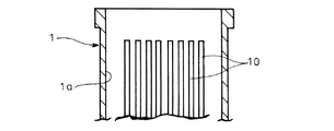
しかしながら、斯かる従来構造においては、ピストン2の摺動方向と平行に延びる縦縞パターンのコーティング部8を採用していたため、該各コーティング部8がシリンダライナ1a内面の同じ場所に押し付けられて摺動することになり、図7に示す如く、シリンダライナ1a内面のコーティング部8が当たる位置に筋状の軽微な段差10(表面粗さが小さくなることで生じた軽微な当たり)ができてしまい、シリンダライナ1aの耐久性に悪影響を及ぼすことが懸念された。
However, in such a conventional structure, since the vertical stripe pattern coating portions 8 extending in parallel with the sliding direction of the
本発明は上述の実情に鑑みてなしたもので、シリンダライナ内面に筋状の軽微な段差を生じることなく摩擦力の大幅な減少を図り得るようにしたピストン摺動部の潤滑構造を提供することを目的としている。 The present invention has been made in view of the above circumstances, and provides a lubricating structure for a piston sliding portion capable of significantly reducing the frictional force without causing a streak-like slight step on the inner surface of a cylinder liner. The purpose is that.
本発明は、エンジンのシリンダ内で往復動するピストンのスカートにおける反スラスト側の外周面に、前記ピストンの摺動方向に延びる縞模様を成すように低摩擦コーティングを施し、そのコーティング部の相互間に前記ピストンの摺動方向に潤滑油を逃がす非コーティング部を残したピストン摺動部の潤滑構造であって、ピストンの摺動に応じ前記各コーティング部の摺動箇所がシリンダライナ内面の同一レベルにおいて前記シリンダライナの周方向に変化し且つ該シリンダライナの内面に対し前記各コーティング部が摺動する範囲が相互間で重複するように該各コーティング部を形成したことを特徴とするものである。 The present invention provides a low friction coating on the outer surface of the piston skirt that reciprocates in the cylinder of the engine on the anti-thrust side so as to form a striped pattern extending in the sliding direction of the piston. The piston sliding portion lubrication structure leaves an uncoated portion that allows lubricating oil to escape in the sliding direction of the piston, and the sliding portion of each coating portion is at the same level on the inner surface of the cylinder liner as the piston slides. The coating portions are formed such that the ranges of the coating portions that change in the circumferential direction of the cylinder liner and the sliding portions of the coating portions slide on the inner surface of the cylinder liner overlap each other. .
而して、このようにすれば、ピストンの摺動に応じ前記各コーティング部の摺動箇所がシリンダライナ内面の同一レベルにおいて前記シリンダライナの周方向に変化するようになっているので、各コーティング部の相互間に非コーティング部を残しながらも、各コーティング部の夫々がシリンダライナ内面に対して摺動する範囲が拡張され、しかも、その各コーティング部が摺動する範囲が相互間で重複するようになっているので、ピストンのスカートの反スラスト側と対峙する範囲内におけるシリンダライナ内面全域が各コーティング部により摺動されることになり、ここに筋状の軽微な段差が生じることが未然に回避される。 Thus, in this way, the sliding portion of each coating portion changes in the circumferential direction of the cylinder liner at the same level on the inner surface of the cylinder liner as the piston slides. While the non-coating portion remains between the portions, the range in which each coating portion slides with respect to the inner surface of the cylinder liner is expanded, and the range in which each coating portion slides overlaps each other. As a result, the entire area of the inner surface of the cylinder liner within the range facing the anti-thrust side of the piston skirt is slid by each coating portion, and there is a possibility that a slight streaky step will occur in this area. To be avoided.
また、このようなコーティング部とした場合であっても、該コーティング部と非コーティング部との境界にコーティング厚さ分のギャップが生じ、実質的なシリンダライナ側との潤滑面が各コーティング部の存在する領域だけに限定されるため、ピストンのスカートにおける潤滑面積が低減されて摩擦力が大幅に減少する効果が従来通り得られる。 Further, even in the case of such a coating portion, a gap corresponding to the coating thickness is generated at the boundary between the coating portion and the non-coating portion, and a substantial lubrication surface with the cylinder liner side is provided on each coating portion. Since it is limited only to the existing region, the lubrication area in the piston skirt is reduced and the frictional force is greatly reduced.
即ち、各コーティング部の相互間に残る非コーティング部は、ピストンの摺動方向に開放されていて潤滑油を自由に逃がし得るようになっているため、各非コーティング部では、流体潤滑の状態にすらならず、潤滑油の粘度も殆ど影響しない非常に摩擦抵抗の少ない状態となるため、実質的なシリンダライナ側との潤滑面は、各コーティング部の存在する領域だけに限定される。 That is, the non-coating parts remaining between the coating parts are opened in the sliding direction of the piston so that the lubricating oil can be released freely. In other words, the frictional resistance is hardly affected by the viscosity of the lubricating oil, so that the substantial frictional surface with the cylinder liner side is limited only to the region where each coating portion exists.
しかも、ピストンのスカートにおける反スラスト側では、各コーティング部とシリンダライナとの間が、油膜を挟んで摩擦面同士が離れて滑っている状態の流体潤滑の状態となるが、各コーティング部の存在する領域では、ピストンクリアランスが詰まってピストンの摺動時における油膜厚さが薄くなり、これにより摩擦係数が小さく抑えられて摩擦力がより少なくなる。 In addition, on the anti-thrust side of the piston skirt, the fluid lubrication state occurs between the coating parts and the cylinder liner, with the friction surfaces sliding apart with the oil film in between. In this area, the piston clearance is clogged and the oil film thickness when the piston is slid is thinned. As a result, the friction coefficient is kept small and the frictional force is reduced.
また、本発明をより具体的に実施するに際しては、各コーティング部をティアドロップ形状とし且つそのティアドロップ形状が隣り合うもの同士で交互に上下が逆向きになるように並べたり、或いは、各コーティング部をピストンの摺動方向に対し同じ向きに所要角度だけ傾斜した帯形状としたりすることが可能である。 Further, when carrying out the present invention more specifically, each coating portion is formed in a teardrop shape and the teardrop shapes are arranged next to each other so that the top and bottom are alternately reversed, or each coating It is possible to make the part into a band shape inclined by a required angle in the same direction with respect to the sliding direction of the piston.
更に、本発明においては、ピストンのスカートにおけるスラスト側の外周面全域に低摩擦コーティングを施すことが好ましく、このようにすれば、金属接触が発生する混合潤滑の状態が支配的となる前記スカートのスラスト側において、その全域が低摩擦コーティングで被覆されていることにより従来通りの耐焼付き性及び低摩擦特性を発揮させることが可能となる。 Furthermore, in the present invention, it is preferable to apply a low friction coating to the entire outer peripheral surface on the thrust side of the skirt of the piston. By doing so, the state of mixed lubrication in which metal contact occurs is dominant. On the thrust side, the entire region is covered with the low friction coating, so that the seizure resistance and the low friction characteristics as usual can be exhibited.
上記した本発明のピストン摺動部の潤滑構造によれば、下記の如き種々の優れた効果を奏し得る。 According to the above-described lubricating structure of the piston sliding portion of the present invention, various excellent effects as described below can be obtained.
(I)本発明の請求項1〜3に記載の発明によれば、各コーティング部の相互間に非コーティング部を残しながらも、各コーティング部の夫々がシリンダライナ内面に対して摺動する範囲を拡張し、その各コーティング部が摺動する範囲を相互間で重複させて、ピストンのスカートの反スラスト側と対峙する範囲内におけるシリンダライナ内面全域を各コーティング部により摺動させることができ、シリンダライナの内面に筋状の軽微な段差を生じることなく摩擦力の大幅な減少を図ることができるので、前記筋状の軽微な段差によりシリンダライナの耐久性に悪影響が及ぶ虞れを払拭することができる。 (I) According to the first to third aspects of the present invention, a range in which each of the coating portions slides with respect to the inner surface of the cylinder liner while leaving an uncoated portion between the coating portions. The range in which each coating portion slides overlaps each other, and the entire area of the cylinder liner inner surface in the range facing the anti-thrust side of the piston skirt can be slid by each coating portion. Since the frictional force can be greatly reduced without causing a streak-like slight step on the inner surface of the cylinder liner, the possibility that the streak-like step may adversely affect the durability of the cylinder liner is eliminated. be able to.
(II)本発明の請求項4に記載の発明によれば、金属接触が発生する混合潤滑の状態が支配的となるピストンのスカートにおけるスラスト側において、その全域を低摩擦コーティングで被覆して従来通りの耐焼付き性及び低摩擦特性を発揮させることができる。 (II) According to the invention described in claim 4 of the present invention, on the thrust side of the piston skirt where the state of mixed lubrication in which metal contact occurs is dominant, the entire region is covered with a low friction coating. The seizure resistance and the low friction characteristic can be exhibited.
以下本発明の実施の形態を図面を参照しつつ説明する。 Embodiments of the present invention will be described below with reference to the drawings.
図1は本発明を実施する形態の一例を示すもので、図4と同一の符号を付した部分は同一物を表わしている。 FIG. 1 shows an example of an embodiment for carrying out the present invention, and parts denoted by the same reference numerals as those in FIG. 4 represent the same items.
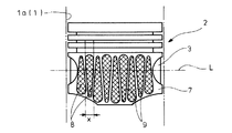
図1に示す如く、本形態例においては、先に説明した図4の従来例と同様に、ピストン2のスカート7における反スラスト側の外周面に、前記ピストン2の摺動方向に向かって延びる縞模様を成すように低摩擦コーティングを施し、そのコーティング部8の相互間に前記ピストン2の摺動方向に潤滑油を逃がす非コーティング部9を残す一方、ピストン2のスカート7におけるスラスト側の外周面全域に低摩擦コーティングを施すようにしているが、各コーティング部8を図4の従来例の如きピストン2の摺動方向と平行に延びる縦縞パターンに替えて、各コーティング部8をティアドロップ形状とし且つそのティアドロップ形状が隣り合うもの同士で交互に上下が逆向きになるように並べている。
As shown in FIG. 1, in this embodiment, as in the conventional example of FIG. 4 described above, the outer peripheral surface of the
即ち、本形態例においては、ピストン2の摺動に応じ前記各コーティング部8の摺動箇所がシリンダライナ1a内面の同一レベルにおいて前記シリンダライナ1aの周方向に変化する形状としてティアドロップ形状を採用しており、例えば、図1中のレベルLを基準とした場合、下方に向け拡幅するティアドロップ形状のコーティング部8(図1中の左から一番目のコーティング部8等)では、ピストン2の上昇に伴いレベルLにおける摺動箇所がシリンダライナ1aの周方向に拡張し、また、上方に向け拡幅する逆さのティアドロップ形状のコーティング部8(図1中の左から二番目のコーティング部8等)では、ピストン2の上昇に伴いレベルLにおける摺動箇所がシリンダライナ1aの周方向に縮小することになる。
That is, in this embodiment, a tear drop shape is adopted as a shape in which the sliding portion of each coating portion 8 changes in the circumferential direction of the
尚、このようなティアドロップ形状のコーティング部8を交互に上下が逆向きになるように並べたことにより、各コーティング部8の相互間には、ピストン2の摺動方向に対し交互に逆向きに所要角度だけ傾斜した直線状の非コーティング部9が残されるようになっている。
In addition, by arranging such tear-drop-shaped coating portions 8 so that the top and bottom are alternately reversed, between the coating portions 8 are alternately reversed with respect to the sliding direction of the
また、ピストン2の周方向における各コーティング部8の最大幅部分の張り出し位置は、隣り合う相手側のコーティング部8の最大幅部分の張り出し位置を超えて張り出すようになっており、例えば、図1中の左から二番目に図示したコーティング部8の最大幅部分の張り出し範囲x内に、その左右のコーティング部8の最大幅部分が入り込んだ配置となっている。
In addition, the protruding position of the maximum width portion of each coating portion 8 in the circumferential direction of the
即ち、ティアドロップ形状としたコーティング部8の最大幅部分の張り出し範囲xとは、シリンダライナ1aの内面に対し前記コーティング部8が摺動する範囲を示しており、換言すれば、シリンダライナ1aの内面に対し前記各コーティング部8が摺動する範囲が相互間で重複するようにしてある。
That is, the overhanging range x of the maximum width portion of the coating portion 8 having a teardrop shape indicates a range in which the coating portion 8 slides with respect to the inner surface of the
而して、このようなティアドロップ形状のコーティング部8とすれば、シリンダライナ1a内面の同一レベルに対し各コーティング部8の摺動箇所がピストン2の摺動に応じてシリンダライナ1aの周方向に拡張又は縮小するようになっているので、各コーティング部8の相互間に非コーティング部9を残しながらも、各コーティング部8の夫々がシリンダライナ1a内面に対して摺動する範囲が拡張され、しかも、その各コーティング部8が摺動する範囲が相互間で重複するようになっているので、ピストン2のスカート7の反スラスト側と対峙する範囲内におけるシリンダライナ1a内面全域が各コーティング部8により摺動されることになり、ここに筋状の軽微な段差が生じることが未然に回避される。
Thus, if such a teardrop-shaped coating portion 8 is used, the sliding position of each coating portion 8 with respect to the same level of the inner surface of the
また、このようなコーティング部8とした場合であっても、該コーティング部8と非コーティング部9との境界にコーティング厚さ分のギャップが生じ、実質的なシリンダライナ1a側との潤滑面が各コーティング部8の存在する領域だけに限定されるため、ピストン2のスカート7における潤滑面積が低減されて摩擦力が大幅に減少する効果が従来通り得られる。
Even in the case of such a coating portion 8, a gap corresponding to the coating thickness is generated at the boundary between the coating portion 8 and the
即ち、各コーティング部8の相互間に残る非コーティング部9は、ピストン2の摺動方向に開放されていて潤滑油を自由に逃がし得るようになっているため、各非コーティング部9では、流体潤滑の状態にすらならず、潤滑油の粘度も殆ど影響しない非常に摩擦抵抗の少ない状態となるため、実質的なシリンダライナ1a側との潤滑面は、各コーティング部8の存在する領域だけに限定される。
That is, the
しかも、ピストン2のスカート7における反スラスト側では、各コーティング部8とシリンダライナ1aとの間が、油膜を挟んで摩擦面同士が離れて滑っている状態の流体潤滑の状態となるが、各コーティング部8の存在する領域では、ピストンクリアランスが詰まってピストン2の摺動時における油膜厚さが薄くなり、これにより摩擦係数が小さく抑えられて摩擦力がより少なくなる。
Moreover, on the anti-thrust side of the
従って、上記形態例によれば、各コーティング部8の相互間に非コーティング部9を残しながらも、各コーティング部8の夫々がシリンダライナ1a内面に対して摺動する範囲を拡張し、その各コーティング部8が摺動する範囲を相互間で重複させて、ピストン2のスカート7の反スラスト側と対峙する範囲内におけるシリンダライナ1a内面全域を各コーティング部8により摺動させることができ、シリンダライナ1aの内面に筋状の軽微な段差を生じることなく摩擦力の大幅な減少を図ることができるので、前記筋状の軽微な段差によりシリンダライナ1aの耐久性に悪影響が及ぶ虞れを払拭することができる。
Therefore, according to the above-described embodiment, while leaving the
また、本形態例においては、ピストン2のスカート7におけるスラスト側の外周面全域に低摩擦コーティングを施しているので、金属接触が発生する混合潤滑の状態が支配的となる前記スカート7のスラスト側において、その全域を低摩擦コーティングで被覆して従来通りの耐焼付き性及び低摩擦特性を発揮させることができる。
In the present embodiment, since the low friction coating is applied to the entire outer peripheral surface on the thrust side of the
即ち、図6のストライベック線図で示す通り、流体潤滑の領域においては、油膜厚さが薄くなるに従い摩擦係数μが小さくなるが、所定の油膜厚さを越えて金属接触が発生する混合潤滑に移行してしまうと、油膜厚さが薄くなるに従い摩擦係数μが急激に増加してしまう。 That is, as shown in the Stribeck diagram of FIG. 6, in the fluid lubrication region, the friction coefficient μ decreases as the oil film thickness decreases, but the mixed lubrication where metal contact occurs beyond a predetermined oil film thickness. , The friction coefficient μ increases rapidly as the oil film thickness decreases.
このため、混合潤滑が支配的なスラスト側にあっては、非コーティング部9を残してしまうことにより該非コーティング部9がシリンダライナ1a側と金属接触を起こして焼付きや摩耗損失を招いてしまうデメリットの方が大きいと考えられ、このようなデメリットを回避することを優先している。
For this reason, on the thrust side where mixed lubrication is dominant, leaving the
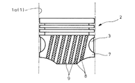
更に、図2は本発明の別の形態例を示すもので、本形態例におけるコーティング部8は、ピストン2の摺動に応じ前記各コーティング部8の摺動箇所がシリンダライナ1a内面の同一レベルにおいて前記シリンダライナ1aの周方向に変化し且つ該シリンダライナ1aの内面に対し前記各コーティング部8が摺動する範囲が相互間で重複するようになっていれば良いので、ここでは各コーティング部8をピストン2の摺動方向に対し同じ向きに所要角度だけ傾斜した帯形状とした例を示している。
Further, FIG. 2 shows another embodiment of the present invention. In the coating portion 8 in this embodiment, the sliding portion of each coating portion 8 is at the same level on the inner surface of the
このようにした場合にも、シリンダライナ1a内面の同一レベルに対し各コーティング部8の摺動箇所がピストン2の摺動に応じてシリンダライナ1aの周方向に移動するようになっているので、各コーティング部8の相互間に非コーティング部9を残しながらも、各コーティング部8がシリンダライナ1a内面に対して摺動する範囲が従来よりも拡張され、しかも、その各コーティング部8が摺動する範囲が相互間で重複するようになっているので、ピストン2のスカート7の反スラスト側と対峙した範囲におけるシリンダライナ1a内面全域が各コーティング部8により摺動され、ここに筋状の軽微な段差が生じることが未然に回避されることになる。
Even in this case, the sliding portion of each coating portion 8 moves in the circumferential direction of the
尚、本発明のピストン摺動部の潤滑構造は、上述の形態例にのみ限定されるものではなく、各コーティング部の形状については、ピストンの摺動に応じ前記各コーティング部の摺動箇所がシリンダライナ内面の同一レベルにおいて前記シリンダライナの周方向に変化し且つ該シリンダライナの内面に対し前記各コーティング部が摺動する範囲が相互間で重複するようになっていれば良く、ティアドロップ形状や斜めの帯形状とすることに限定されないこと、その他、本発明の要旨を逸脱しない範囲内において種々変更を加え得ることは勿論である。 In addition, the lubricating structure of the piston sliding portion of the present invention is not limited to the above-described embodiment, and the shape of each coating portion is determined by the sliding portion of each coating portion according to the piston sliding. It is only necessary to change the circumferential direction of the cylinder liner at the same level on the inner surface of the cylinder liner and to allow the ranges where the coating portions slide relative to the inner surface of the cylinder liner to overlap each other. Of course, the invention is not limited to the shape of a slanted belt, and various modifications can be made without departing from the scope of the present invention.
1 シリンダ
1a シリンダライナ
2 ピストン
7 スカート
8 コーティング部
9 非コーティング部
1
Claims (4)
Priority Applications (1)
| Application Number | Priority Date | Filing Date | Title |
|---|---|---|---|
| JP2011154431A JP5840881B2 (en) | 2011-07-13 | 2011-07-13 | Piston sliding part lubrication structure |
Applications Claiming Priority (1)
| Application Number | Priority Date | Filing Date | Title |
|---|---|---|---|
| JP2011154431A JP5840881B2 (en) | 2011-07-13 | 2011-07-13 | Piston sliding part lubrication structure |
Publications (2)
| Publication Number | Publication Date |
|---|---|
| JP2013019366A true JP2013019366A (en) | 2013-01-31 |
| JP5840881B2 JP5840881B2 (en) | 2016-01-06 |
Family
ID=47691028
Family Applications (1)
| Application Number | Title | Priority Date | Filing Date |
|---|---|---|---|
| JP2011154431A Active JP5840881B2 (en) | 2011-07-13 | 2011-07-13 | Piston sliding part lubrication structure |
Country Status (1)
| Country | Link |
|---|---|
| JP (1) | JP5840881B2 (en) |
Cited By (5)
| Publication number | Priority date | Publication date | Assignee | Title |
|---|---|---|---|---|
| JP2015025382A (en) * | 2013-07-25 | 2015-02-05 | 日野自動車株式会社 | Slide part lubrication structure of piston |
| CN105221284A (en) * | 2015-11-11 | 2016-01-06 | 江苏大学 | Internal combustion engine cylinder jacket |
| CN105221283A (en) * | 2015-09-22 | 2016-01-06 | 江苏大学 | A kind of engine cylinder hole and processing method thereof |
| JP2016121562A (en) * | 2014-12-24 | 2016-07-07 | 株式会社豊田自動織機 | Internal combustion engine piston |
| CN109026427A (en) * | 2018-09-30 | 2018-12-18 | 滨州学院 | Novel forging steel piston |
Citations (3)
| Publication number | Priority date | Publication date | Assignee | Title |
|---|---|---|---|---|
| JP2007509279A (en) * | 2003-10-23 | 2007-04-12 | マーレ ゲゼルシヤフト ミツト ベシユレンクテル ハフツング | Piston with patterned coating and method for providing patterned coating |
| JP2009030521A (en) * | 2007-07-26 | 2009-02-12 | Toyota Motor Corp | Piston |
| JP2010106724A (en) * | 2008-10-29 | 2010-05-13 | Hino Motors Ltd | Lubricating structure of piston sliding part |
-
2011
- 2011-07-13 JP JP2011154431A patent/JP5840881B2/en active Active
Patent Citations (3)
| Publication number | Priority date | Publication date | Assignee | Title |
|---|---|---|---|---|
| JP2007509279A (en) * | 2003-10-23 | 2007-04-12 | マーレ ゲゼルシヤフト ミツト ベシユレンクテル ハフツング | Piston with patterned coating and method for providing patterned coating |
| JP2009030521A (en) * | 2007-07-26 | 2009-02-12 | Toyota Motor Corp | Piston |
| JP2010106724A (en) * | 2008-10-29 | 2010-05-13 | Hino Motors Ltd | Lubricating structure of piston sliding part |
Cited By (7)
| Publication number | Priority date | Publication date | Assignee | Title |
|---|---|---|---|---|
| JP2015025382A (en) * | 2013-07-25 | 2015-02-05 | 日野自動車株式会社 | Slide part lubrication structure of piston |
| JP2016121562A (en) * | 2014-12-24 | 2016-07-07 | 株式会社豊田自動織機 | Internal combustion engine piston |
| US9885312B2 (en) | 2014-12-24 | 2018-02-06 | Kabushiki Kaisha Toyota Jidoshokki | Piston for internal combustion engine |
| DE102015122364B4 (en) * | 2014-12-24 | 2021-05-12 | Kabushiki Kaisha Toyota Jidoshokki | PISTON FOR A COMBUSTION ENGINE |
| CN105221283A (en) * | 2015-09-22 | 2016-01-06 | 江苏大学 | A kind of engine cylinder hole and processing method thereof |
| CN105221284A (en) * | 2015-11-11 | 2016-01-06 | 江苏大学 | Internal combustion engine cylinder jacket |
| CN109026427A (en) * | 2018-09-30 | 2018-12-18 | 滨州学院 | Novel forging steel piston |
Also Published As
| Publication number | Publication date |
|---|---|
| JP5840881B2 (en) | 2016-01-06 |
Similar Documents
| Publication | Publication Date | Title |
|---|---|---|
| JP5840881B2 (en) | Piston sliding part lubrication structure | |
| JP2014001732A (en) | Coating with nonconstant thickness for cylinder liner | |
| JP6394485B2 (en) | Piston of internal combustion engine | |
| JP5122420B2 (en) | Piston sliding part lubrication structure | |
| CN102362106B (en) | Compression piston ring | |
| JP2009030521A (en) | Piston | |
| JP2009091927A (en) | Piston ring for reciprocating engine | |
| JPWO2017209135A1 (en) | Sliding structure of internal combustion engine, control method of idling operation, operation control method of internal combustion engine | |
| JP5918107B2 (en) | Piston of internal combustion engine | |
| JP2005226522A (en) | Piston device for internal combustion engine | |
| JP2016205236A (en) | Engine piston | |
| JP6259585B2 (en) | Piston sliding part lubrication structure | |
| CN106337755A (en) | Piston Ring Configured To Reduce Friction | |
| JP6153803B2 (en) | Piston sliding part lubrication structure | |
| JP5550870B2 (en) | Combined oil ring for internal combustion engine and its assembly structure | |
| JP2005264978A (en) | Pressure ring | |
| JP7045383B2 (en) | piston ring | |
| US20080017025A1 (en) | Variable Tension Ring Mechanism | |
| JP6366807B2 (en) | Piston sliding part lubrication structure | |
| JP2021121755A (en) | Combination oil ring and oil ring fitting piston | |
| JP2011052607A (en) | Piston of internal combustion engine | |
| JP2016118276A (en) | Combination oil ring | |
| JP5564133B2 (en) | Piston of internal combustion engine | |
| US8876115B2 (en) | Three-piece oil-control ring for an internal combustion engine | |
| JP2008115936A (en) | Connecting rod |
Legal Events
| Date | Code | Title | Description |
|---|---|---|---|
| A621 | Written request for application examination |
Free format text: JAPANESE INTERMEDIATE CODE: A621 Effective date: 20140627 |
|
| A131 | Notification of reasons for refusal |
Free format text: JAPANESE INTERMEDIATE CODE: A131 Effective date: 20150224 |
|
| A977 | Report on retrieval |
Free format text: JAPANESE INTERMEDIATE CODE: A971007 Effective date: 20150227 |
|
| A521 | Request for written amendment filed |
Free format text: JAPANESE INTERMEDIATE CODE: A523 Effective date: 20150413 |
|
| TRDD | Decision of grant or rejection written | ||
| A01 | Written decision to grant a patent or to grant a registration (utility model) |
Free format text: JAPANESE INTERMEDIATE CODE: A01 Effective date: 20151104 |
|
| A61 | First payment of annual fees (during grant procedure) |
Free format text: JAPANESE INTERMEDIATE CODE: A61 Effective date: 20151112 |
|
| R150 | Certificate of patent or registration of utility model |
Ref document number: 5840881 Country of ref document: JP Free format text: JAPANESE INTERMEDIATE CODE: R150 |
|
| R250 | Receipt of annual fees |
Free format text: JAPANESE INTERMEDIATE CODE: R250 |
|
| R250 | Receipt of annual fees |
Free format text: JAPANESE INTERMEDIATE CODE: R250 |
|
| R250 | Receipt of annual fees |
Free format text: JAPANESE INTERMEDIATE CODE: R250 |
|
| R250 | Receipt of annual fees |
Free format text: JAPANESE INTERMEDIATE CODE: R250 |