JP2013018235A - Method for producing rubber roll - Google Patents
Method for producing rubber roll Download PDFInfo
- Publication number
- JP2013018235A JP2013018235A JP2011154880A JP2011154880A JP2013018235A JP 2013018235 A JP2013018235 A JP 2013018235A JP 2011154880 A JP2011154880 A JP 2011154880A JP 2011154880 A JP2011154880 A JP 2011154880A JP 2013018235 A JP2013018235 A JP 2013018235A
- Authority
- JP
- Japan
- Prior art keywords
- mold
- cylindrical
- jig
- core metal
- hole
- Prior art date
- Legal status (The legal status is an assumption and is not a legal conclusion. Google has not performed a legal analysis and makes no representation as to the accuracy of the status listed.)
- Granted
Links
Images


Abstract
Description
本発明は、ゴムロールの製造方法に関する。 The present invention relates to a method for producing a rubber roll.
従来の樹脂被覆ロール(ゴムロール)の製造は、円筒金型の内部に樹脂チューブと芯金を入れ、樹脂チューブ及び芯金の両端を保持するように、円筒金型の両端にそれぞれ上金型及び下金型をセットし、芯金と樹脂チューブとの間にシリコーンゴムを注入して加熱していた(例えば、特許文献1参照)。 A conventional resin-coated roll (rubber roll) is manufactured by placing a resin tube and a cored bar inside a cylindrical mold, and holding both ends of the cylindrical tube and the upper mold and A lower mold was set, and silicone rubber was injected between the core metal and the resin tube and heated (see, for example, Patent Document 1).
本発明は、金型の内部に芯金を入れる際、その芯金が金型の内壁や金型の内壁に設けられた被膜部材に接触するのを防止できるゴムロールの製造方法を得ることを目的とする。 An object of the present invention is to obtain a rubber roll manufacturing method capable of preventing the core metal from contacting the inner wall of the mold or the coating member provided on the inner wall of the mold when the core metal is placed inside the mold. And
上記の目的を達成するために、本発明に係る請求項1に記載のゴムロールの製造方法は、円筒形状の第1金型の一端に、中央に円形の貫通孔が形成された筒状の治具を装着する治具装着工程と、前記治具の前記貫通孔を通して、円筒形状又は円柱形状の芯金を前記第1金型内に挿入し、前記芯金の一端を、前記第1金型の他端に装着されている又は装着されつつある第2金型に形成された凹部に挿入する芯金挿入工程と、前記第1金型の一端に装着した前記治具を取り外し、代わりに第3金型を前記第1金型の一端に装着するとともに、前記芯金の他端を前記第3金型に形成された凹部に挿入する金型装着工程と、前記第2金型及び前記第3金型の少なくとも一方に形成された注入口から未加硫ゴムを注入し、前記芯金と前記第1金型の内壁面との間に、前記未加硫ゴムを充填する充填工程と、前記未加硫ゴムを硬化する硬化工程と、を含み、前記芯金挿入工程において、前記貫通孔の内径と前記芯金の外径との差をA、前記第1金型の内径と前記貫通孔の内径との差の半分をB、前記貫通孔の内壁面の軸方向における長さをL、前記第1金型の前記第2金型側における他端面から前記治具の外端面までの軸方向における長さDから、前記長さLを減算した長さをCとしたときに、L>A×C÷Bの関係を満たすことを特徴としている。 In order to achieve the above object, a rubber roll manufacturing method according to claim 1 of the present invention is a cylindrical jig in which a circular through-hole is formed in the center at one end of a cylindrical first mold. A jig mounting step for mounting a tool, and a cylindrical or columnar cored bar is inserted into the first mold through the through hole of the jig, and one end of the cored bar is inserted into the first mold. A cored bar insertion step for inserting into a recess formed in the second mold that is or is being mounted on the other end of the first mold, and the jig mounted on one end of the first mold is removed, A mold mounting step of mounting a three mold on one end of the first mold and inserting the other end of the core into a recess formed in the third mold; and the second mold and the second mold Unvulcanized rubber is injected from an injection port formed in at least one of the three molds, and the core metal and the inner wall of the first mold A filling step for filling the unvulcanized rubber, and a curing step for curing the unvulcanized rubber. In the cored bar insertion step, the inner diameter of the through hole and the outer side of the cored bar A difference in diameter is A, half of the difference between the inner diameter of the first mold and the inner diameter of the through hole is B, the length of the inner wall surface of the through hole in the axial direction is L, and the first mold has the When the length obtained by subtracting the length L from the length D in the axial direction from the other end surface on the second mold side to the outer end surface of the jig is C, a relationship of L> A × C ÷ B It is characterized by satisfying.
また、本発明に係る請求項2に記載のゴムロールの製造方法は、円筒形状の第1金型の一端に、中央に円形の貫通孔が形成された筒状の治具を装着する治具装着工程と、前記治具の前記貫通孔を通して、円筒形状又は円柱形状の芯金を前記第1金型内に挿入し、前記芯金の一端を、前記第1金型の他端に装着されている又は装着されつつある第2金型に形成された凹部に挿入する芯金挿入工程と、前記第1金型の一端に装着した前記治具を取り外し、代わりに第3金型を前記第1金型の一端に装着するとともに、前記芯金の他端を前記第3金型に形成された凹部に挿入する金型装着工程と、前記第2金型及び前記第3金型の少なくとも一方に形成された注入口から未加硫ゴムを注入し、前記芯金と前記第1金型の内壁面との間に、前記未加硫ゴムを充填する充填工程と、前記未加硫ゴムを硬化する硬化工程と、を含み、前記芯金挿入工程において、前記芯金が傾いても該芯金を前記貫通孔の内壁縁部で規制して、前記第1金型の内壁面に接触しないように構成された前記治具を用いることを特徴としている。 According to a second aspect of the present invention, there is provided the rubber roll manufacturing method according to the first aspect of the present invention, wherein a jig for attaching a cylindrical jig having a circular through hole formed in the center to one end of a cylindrical first mold is provided. A cylindrical metal or columnar core is inserted into the first mold through the step and the through hole of the jig, and one end of the core is attached to the other end of the first mold. A cored bar insertion step for inserting into a recess formed in the second mold being or being mounted, and the jig mounted on one end of the first mold is removed, and a third mold is replaced with the first mold At least one of the second die and the third die is attached to one end of the die, and the other end of the core is inserted into a recess formed in the third die. Unvulcanized rubber is injected from the formed inlet, and the unvulcanized rubber is interposed between the core metal and the inner wall surface of the first mold. A filling step of filling the core and a curing step of curing the unvulcanized rubber, and in the cored bar insertion step, the cored bar is regulated by an inner wall edge of the through hole even if the cored bar is inclined. And the said jig | tool comprised so that it may not contact the inner wall face of a said 1st metal mold | die is used, It is characterized by the above-mentioned.
また、請求項3に記載のゴムロールの製造方法は、請求項1又は請求項2に記載のゴムロールの製造方法であって、前記治具装着工程の前に、円筒形状の被膜部材を前記第1金型の内壁面に装着する被膜装着工程を含むことを特徴としている。 The rubber roll manufacturing method according to claim 3 is the rubber roll manufacturing method according to claim 1 or 2, wherein the cylindrical coating member is attached to the first roll before the jig mounting step. It is characterized by including a film mounting step for mounting on the inner wall surface of the mold.
請求項1に記載の発明によれば、金型の内部に治具を用いないで芯金を入れる場合に比べて、その芯金が金型の内壁に接触するのを防止することができる。 According to the first aspect of the present invention, it is possible to prevent the core metal from contacting the inner wall of the mold as compared with the case where the core metal is inserted without using a jig inside the mold.
請求項2に記載の発明によれば、金型の内部に治具を用いないで芯金を入れる場合に比べて、その芯金が金型の内壁に接触するのを防止することができる。 According to the second aspect of the present invention, it is possible to prevent the cored bar from coming into contact with the inner wall of the mold as compared with the case where the cored bar is inserted without using a jig inside the mold.
請求項3に記載の発明によれば、金型の内部に治具を用いないで芯金を入れる場合に比べて、その芯金が金型の内壁に設けられた被膜部材に接触するのを防止することができる。 According to the third aspect of the present invention, the core metal comes into contact with the coating member provided on the inner wall of the mold as compared with the case where the core metal is inserted without using a jig inside the mold. Can be prevented.
以下、本発明に係る実施の形態について、図面を基に詳細に説明する。なお、説明の便宜上、各図において適宜記す矢印UPを上方向とし、それを基準に「上」、「下」を付加して説明するが、「上」、「下」を付加した説明によって、各部の方向が限定されるものではない。また、以下において、「平面視」とは、上方から見ることを言う。 Hereinafter, embodiments according to the present invention will be described in detail with reference to the drawings. For convenience of explanation, an arrow UP appropriately described in each figure is an upward direction, and “upper” and “lower” are added as a reference. The direction of each part is not limited. In the following, “plan view” refers to viewing from above.
(ゴムロールの製造装置)
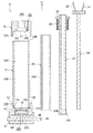
図1〜図3で示すように、ゴムロールR(図6参照)の製造装置の一例としての金型10は、後述する芯金20を同軸状に包囲する円筒形状の第1金型の一例としての円筒金型12と、円筒金型12の下端部(他端)に軸方向外側から装着される第2金型の一例としての下金型14と、円筒金型12の上端部(一端)に軸方向外側から装着される第3金型の一例としての上金型16と、下金型14の下端部に軸方向外側から装着されるゲートキャップ18と、を有している。
(Rubber roll manufacturing equipment)
As shown in FIGS. 1-3, the metal mold | die 10 as an example of the manufacturing apparatus of the rubber roll R (refer FIG. 6) is an example of the cylindrical 1st metal mold | die which surrounds the
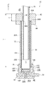
また、この金型10には、円筒金型12内に挿入され、下金型14と上金型16とで軸方向外側から挟持される円筒形状の芯金20と、その芯金20内に挿入される有底円筒形状のセンターシャフト22と、センターシャフト22内に挿入される電熱式のパイプヒーター24と、が備えられている。そして、ゴムロールRの製造時、芯金20の外周面20Aと円筒金型12の内壁面12Aとの間には、ゴム層成形空間Sが形成されるようになっている(図3参照)。
The
図2、図3で示すように、下金型14は、内周面側にOリング15が設けられ、円筒金型12の下端部を外側から被覆するように、その下端部に嵌められる外筒部14Aと、内周面側にOリング15が設けられ、円筒金型12内に挿入された芯金20の下端部(一端)を外側から被覆するように、その下端部に嵌められる凹部の一例としての内筒部14Bと、を有している。
As shown in FIGS. 2 and 3, the
つまり、外筒部14Aの内径は、円筒金型12の外径と略同一とされ、内筒部14Bの内径は、芯金20の外径と略同一とされている。そして、外筒部14Aの径方向内側で、かつ内筒部14Bよりも径方向外側には、円筒金型12の下端面12C(他端面の一例)が対向する(後述する樹脂フィルム38の下端部38Aを間に挟んで当たる)内端面14Cが環状に形成されている。
That is, the inner diameter of the
同様に、上金型16は、円筒金型12の上端部を外側から被覆するように、その上端部に嵌められる外筒部16Aと、内周面側にOリング15が設けられ、円筒金型12内に挿入された芯金20の上端部(他端)を外側から被覆するように、その上端部に嵌められる凹部の一例としての内筒部16Bと、を有している。
Similarly, the
つまり、外筒部16Aの内径は、円筒金型12の外径と略同一とされ、内筒部16Bの内径は、芯金20の外径と略同一とされている。そして、外筒部16Aの径方向内側で、かつ内筒部16Bの径方向外側には、円筒金型12の上端面12Dが対向する(後述する樹脂フィルム38の上端部38Bを間に挟んで当たる)内端面16Cが環状に形成されている。
That is, the inner diameter of the
また、上金型16の軸心部で、かつ内筒部16Bよりも径方向内側には、センターシャフト22を挿通させるための平面視円形状の貫通孔16Dが上下方向に沿って形成されている。そして、内端面16C上の予め決められた位置には、ゴム層成形空間Sと大気とを通じさせる平面視円形状の貫通孔であるエアーベント16Eが上下方向に沿って形成されている。
A through
更に、下金型14の内筒部14Bと外筒部14Aとの間には、未加硫ゴムの流通路14Dが上下方向に沿って形成されている。この流通路14Dは、周方向に等間隔で複数形成されており、各流通路14Dの上方側は、ゴム層成形空間S(図3参照)に通じている。そして、各流通路14Dの下方側は、下金型14の軸心部に形成された未加硫ゴムの注入口14Eに通じている。
Further, between the
また、ゲートキャップ18の軸心部には、下金型14の注入口14Eに通じる未加硫ゴムの注入路18Aが上下方向に沿って形成されている。そして、このゲートキャップ18には、円筒金型12の軸方向と直交する方向に延在し、注入路18Aと交差する円柱形状のシャッターピン36が摺動自在に取り付けられている。そして更に、このシャッターピン36の注入路18Aに対応する部位には、その注入路18Aと通じる未加硫ゴムの流通孔36Aが上下方向に沿って形成されている。
Further, an unvulcanized
センターシャフト22の上端外周面には、ネジ部22A(図1参照)が形成されており、センターシャフト22の下端周縁部には、下金型14の内筒部14Bよりも下方側に形成された被係止部14Fに係止される係止部22Bが一体に形成されている。また、センターシャフト22のネジ部22Aには、ナット26が螺着されており、ゴム層成形空間Sに未加硫ゴムを充填してゴムロールRを製造する際に、金型10の型締め圧を調整するコイルスプリング28が、ナット26の下面と上金型16の上面との間に配設可能になっている。
A
電熱式のパイプヒーター24の内部には、図示しない電熱線が挿入されており、その電熱線には、パイプヒーター24の上端部において、電線32が結線されている。また、パイプヒーター24の上端部には、パイプヒーター24の温度を測定するための熱電対34が取り付けられている。
A heating wire (not shown) is inserted into the electric heating
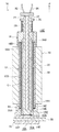
また、図4、図5で示すように、この金型10には、円筒金型12を冷却するための冷却筒30が装着(外嵌)されるようになっている。この冷却筒30は、2つ割り構造の円筒形状とされ、その高さは下金型14の外筒部14Aにおける上端面と、上金型16の外筒部16Aにおける下端面との間の間隔と略同一とされている。
As shown in FIGS. 4 and 5, a
つまり、この冷却筒30は、下金型14と上金型16との間における円筒金型12の外壁面12B全体を被覆するような大きさに形成されている。そして、冷却筒30の周壁内には、冷却水の通路30Aが上下方向に沿って、かつ周方向に等間隔で複数形成されており、その通路30A内には、例えば約10℃の温度に設定された冷却水が送通されるようになっている。
That is, the
また、この金型10には、図1、図7、図8で示すように、円筒金型12内に芯金20を挿入する際に、その円筒金型12の上端部に装着され、芯金20が円筒金型12の軸方向に対して傾いても、芯金20の下端周縁部20Bが、円筒金型12の内壁面12Aに接触しないようにする芯金挿入用の治具の一例としての補助具40が備えられている。
Further, as shown in FIGS. 1, 7, and 8, when the
この補助具40は、軸心部に平面視円形状の貫通孔42が形成された円筒形状に形成されており、その軸方向内側には、円筒金型12の上端部を外側から被覆するように、その上端部に嵌められる外筒部44が形成されている。そして、芯金20は、貫通孔42から挿入されるようになっている。
The
つまり、この貫通孔42の内径は、芯金20の外径よりも大きく形成されており、円筒金型12の内径よりも小さく形成されている。そして、円筒金型12の下端部に下金型14が装着され、円筒金型12の上端部に補助具40が装着された状態で、各部の寸法関係は、次のようになっている。
That is, the inner diameter of the through
すなわち、貫通孔42の内径と芯金20の外径との差をA、円筒金型12の内径と貫通孔42の内径との差の1/2(半分)をB、貫通孔42の内壁面46の軸方向における長さをL(図7参照)、円筒金型12の下端面12C(下金型14の内端面14C)から補助具40の外端面(上端面)40Aまでの軸方向における長さD(図7参照)から、長さLを減算した長さをC(=D−L)としたときに、L>A×C÷Bの関係を満たすようになっている。
That is, A is the difference between the inner diameter of the through
これにより、円筒金型12内に芯金20を人手により(重力により)挿入する際に、芯金20が円筒金型12の軸方向に対して傾いて、芯金20の外周面20Aが内壁面46の下端周縁部46A(内壁縁部の一例)に接触しても、芯金20の下端周縁部20Bが円筒金型12の内壁面12A(後述する樹脂フィルム38)に接触しないようにできる構成である(図8参照)。
Thus, when the
なお、長さDは、内筒部14Bの上端面から補助具40の外端面(上端面)40Aまでの長さとしてもよい。この場合は、下金型14の内壁面も保護される。つまり、この長さDは、少なくとも円筒金型12の下端面12C(又はその下端面12Cが円筒金型12の軸方向で対向する下金型14の内端面14C)から補助具40の外端面(上端面)40Aまでの長さとされていればよい。
The length D may be a length from the upper end surface of the inner
また、ゴムロールRを製造する際、芯金20を円筒金型12内に挿入する前に、円筒金型12内に、円筒形状の被膜部材の一例としてのフッ素樹脂チューブ(以下「樹脂フィルム」という)38を挿入し、円筒金型12の内壁面12A側から真空引き(減圧)し、その樹脂フィルム38の外周面を円筒金型12の内壁面12Aに貼り付かせる場合がある。
Further, when the rubber roll R is manufactured, before the
つまり、図6で示すように、製造されたゴムロールRの外周面に樹脂フィルム38(フッ素樹脂層)が被膜されている場合がある。この場合、円筒金型12の内径には、樹脂フィルム38の膜厚も考慮されるが、樹脂フィルム38の膜厚は30μm程度なので、円筒金型12の内径として、上記Bの値を算出しても、実質的には大差がない。
That is, as shown in FIG. 6, the resin film 38 (fluororesin layer) may be coated on the outer peripheral surface of the manufactured rubber roll R. In this case, although the film thickness of the
また、芯金20は、下金型14が円筒金型12の下端部に装着された後に、円筒金型12内に挿入される場合に限定されるものではなく、例えば円筒金型12の下端部に芯金受止治具(図示省略)を装着しておき、補助具40を用いて芯金20を円筒金型12内に挿入した後、その芯金受止治具を円筒金型12から取り外すとともに、下金型14を円筒金型12に装着し、その後(又は装着しつつ)、芯金20の下端部を内筒部14Bに嵌合させるようにしてもよい。
The
なお、芯金受止治具としては、補助具40から貫通孔42を無くしたものを例示することができる。また、芯金20は、例えばアルミニウム、鉄、銅、ステンレススチール又はその他の金属や合金等で成形されている。そして、芯金20の外周面20Aと円筒金型12の内壁面12Aとの間のゴム層成形空間S内に注入(充填)されるゴム材としては、例えばシリコーンゴムやウレタンゴム等が一例として挙げられる。
In addition, as a metal core receiving jig, the thing which eliminated the through-
(ゴムロールの製造方法)
以上のような構成の補助具40を備えた金型10において、次にその作用(ゴムロールRの製造方法)について説明する。まず、円筒金型12内にフッ素樹脂チューブ(樹脂フィルム38)を挿入し、真空引き(減圧)することにより、円筒金型12の内壁面12Aに、樹脂フィルム38の外周面を貼付させる(被膜装着工程)。なお、樹脂フィルム38の軸方向における長さは、その下端部38A及び上端部38Bが、円筒金型12から軸方向外側へ少しはみ出る長さとされている。
(Rubber roll manufacturing method)
Next, the operation of the
その後、円筒金型12の下端部に下金型14を装着するとともに、下金型14の下端部にゲートキャップ18を装着する。そして、図7で示すように、円筒金型12の上端部に補助具40を装着する(治具装着工程)。そして更に、その貫通孔42から芯金20を円筒金型12内に挿入するとともに、下金型14の内筒部14B(凹部)に、芯金20の下端部を嵌合する(芯金挿入工程)。
Thereafter, the
なお、このとき、円筒金型12、下金型14、補助具40における各部の寸法は、上記の通り、貫通孔42の内径と芯金20の外径との差をA、円筒金型12の内径と貫通孔42の内径との差の1/2(半分)をB、貫通孔42の内壁面46の軸方向における長さをL、円筒金型12の下端面12C(下金型14の内端面14C)から補助具40の外端面40Aまでの軸方向における長さDから、長さLを減算した長さをCとしたときに、L>A×C÷Bの関係を満たすようになっている。
At this time, the dimensions of each part in the
したがって、図8で示すように、芯金20が円筒金型12の軸方向に対して傾いて、その外周面20Aが、補助具40の内壁面46の下端周縁部46Aに接触しても、その下端周縁部20Bが、円筒金型12の内壁面12A、詳細には樹脂フィルム38に接触することがない。つまり、これにより、円筒金型12の内壁面12Aや樹脂フィルム38が、その芯金20の下端周縁部20Bによって損傷する(破れや擦り傷が発生する)おそれがない。
Therefore, as shown in FIG. 8, even when the
こうして、円筒金型12内に芯金20を挿入し、その下端部を下金型14の内筒部14Bに嵌合させたら、円筒金型12の上端部から補助具40を取り外し、代わりに上金型16を、その円筒金型12の上端部に装着しつつ、上金型16の内筒部16B(凹部)に、芯金20の上端部を嵌合する(金型装着工程)。
In this way, when the
これにより、芯金20が、円筒金型12に同軸状に包囲されつつ、下金型14及び上金型16によって、その軸方向外側から内側に向けて狭持される。なお、このとき、樹脂フィルム38の下端部38A及び上端部38Bも、それぞれ円筒金型12と下金型14との間、及び円筒金型12と上金型16との間で押さえられる(図3参照)。
Thereby, the cored
こうして、円筒金型12の下端部に下金型14が装着され、円筒金型12の上端部に上金型16が装着されたら、センターシャフト22を、上金型16の貫通孔16Dを通して、芯金20内に挿入する。そして、下金型14の内筒部14Bの下方側に形成されている被係止部14Fに、係止部22Bを係止させる。
Thus, when the
そして更に、ナット26を回転させ、ナット26の下面と上金型16の上面との間に配設されているコイルスプリング28の付勢力を調節し、金型10の型締め圧を調整する。次いで、そのセンターシャフト22内にパイプヒーター24を挿入する。この状態が図3で示されている。なお、パイプヒーター24が予め挿入されているセンターシャフト22を、貫通孔16Dを通して、芯金20内に挿入するようにしてもよい。
Further, the
こうして、金型10の組み付けが完了したら、ゲートキャップ18のシャッターピン36を摺動させて、シャッターピン36の流通孔36Aとゲートキャップ18の注入路18Aとの位置を合わせる。そして、ゲートキャップ18の注入路18Aから、下金型14に形成されている注入口14E及び流通路14Dを介して、ゴム層成形空間S内に未加硫ゴムを予め決められた圧力で注入する(充填工程)。
Thus, when the assembly of the
すると、未加硫ゴムは、その圧力と重力の作用によって、芯金20の外周面20Aと円筒金型12の内壁面12A(樹脂フィルム38)との間に形成されたゴム層成形空間S内を埋め尽くすように充填される。そして、その未加硫ゴムの充填が完了したら、シャッターピン36を摺動させて、シャッターピン36の流通孔36Aとゲートキャップ18の注入路18Aとの位置をずらし、未加硫ゴムの注入を停止する。
Then, the unvulcanized rubber is in the rubber layer molding space S formed between the outer
その後、パイプヒーター24に通電して、ゴム層成形空間S内に充填された未加硫ゴムを加熱し、その未加硫ゴムを硬化させることによって、図5で示す加硫ゴム層Gを形成する(硬化工程)。なお、このとき、パイプヒーター24に取り付けられている熱電対34によって、パイプヒーター24の温度を測定し、未加硫ゴムに対する加熱温度を調整する。
Thereafter, the
こうして、未加硫ゴムを加熱して硬化させ、加硫ゴム層Gを形成したら、パイプヒーター24への通電を切り、パイプヒーター24をセンターシャフト22内に挿入した状態のまま(又はパイプヒーター24をセンターシャフト22内から取り出してから)、冷却筒30を円筒金型12の外壁面12Bに外嵌(装着)させる。そして、冷却筒30の通路30Aに冷却水を送通し、円筒金型12を冷却する。
Thus, after the unvulcanized rubber is heated and cured to form the vulcanized rubber layer G, the
円筒金型12に対する冷却が完了したら、円筒金型12から冷却筒30を取り外し、芯金20内からセンターシャフト22(パイプヒーター24を含む場合もある)を取り外すとともに、上金型16を円筒金型12から取り外す。そして、円筒金型12内から、図6で示すゴムロールR(樹脂被覆ロール)を取り出す。
When the cooling of the
こうして製造されたゴムロールRは、補助具40を使用することによって芯金20が円筒金型12内に挿入されていることから、その外周面(樹脂フィルム38)には、破れや擦り傷等が発生していない。したがって、このゴムロールRを、例えば定着装置(図示省略)のヒートロールとして使用した場合には、その破れや擦り傷が原因の画像欠陥(画質低下)が発生しない。
In the rubber roll R manufactured in this way, since the
(補助具の変形例)
また、補助具40としては、図9で示す形状のものであってもよい。すなわち、この変形例に係る補助具41では、貫通孔42の内壁面46の長さが、上記補助具40の場合よりも長く形成されている。つまり、この補助具41には、円筒金型12内に挿入される内筒部48が形成されており、芯金20の円筒金型12の軸方向に対する傾きをより一層規制できるようになっている。
(Modification of assistive device)
Further, the
そして、この補助具41においても、貫通孔42の内径と芯金20の外径との差をA、円筒金型12の内径と貫通孔42の内径との差の1/2(半分)をB、貫通孔42の内壁面46の軸方向における長さをL、円筒金型12の下端面12C(下金型14の内端面14C)から補助具41の外端面41Aまでの軸方向における長さDから、長さLを減算した長さをC(=D−L)としたときに、L>A×C÷Bの関係を満たすようになっている。
Also in this auxiliary tool 41, the difference between the inner diameter of the through
したがって、貫通孔42から芯金20を円筒金型12内に挿入するときに、その芯金20が円筒金型12の軸方向に対して傾いて、その外周面20Aが、補助具41の内壁面46(内筒部48)の下端周縁部46Aに接触しても、その下端周縁部20Bが、円筒金型12の内壁面12A、詳細には樹脂フィルム38に接触することがない。つまり、この場合も、円筒金型12の内壁面12Aや樹脂フィルム38が、芯金20の下端周縁部20Bによって損傷する(破れや擦り傷が発生する)おそれがない。
Therefore, when the
以上、本実施形態に係るゴムロールRの製造方法について、図面を基に説明したが、本実施形態に係るゴムロールRの製造方法は、図示のものに限定されるものではなく、種々の変形、変更、改良が可能である。例えば、フッ素樹脂層としての樹脂フィルム38が設けられていないゴムロールRを製造する場合にも、本実施形態に係るゴムロールRの製造方法を適用することが可能である。
As mentioned above, although the manufacturing method of the rubber roll R which concerns on this embodiment was demonstrated based on drawing, the manufacturing method of the rubber roll R which concerns on this embodiment is not limited to the thing of illustration, Various deformation | transformation and change Improvements are possible. For example, also when manufacturing the rubber roll R in which the
この場合、貫通孔42から芯金20を円筒金型12内に挿入するときに、芯金20が円筒金型12の軸方向に対して傾いて、芯金20の外周面20Aが、補助具40、41の内壁面46(内筒部48)の下端周縁部46Aに接触しても、芯金20の下端周縁部20Bが、円筒金型12の内壁面12Aに接触することがない。このため、円筒金型12の内壁面12Aに傷が発生することがなく、その内壁面12Aが転写して形成される外周面に傷が無いゴムロールRを製造することができる。
In this case, when the
また、芯金20は、円筒形状に限定されるものではなく、円柱形状に形成されていてもよい。すなわち、このゴムロールRは、定着装置のヒートロールとして使用される場合に限定されるものではない。更に、未加硫ゴムの注入口14E及び流通路14D等は、上金型16に形成する構成にしてもよく、この注入口14E及び流通路14D等は、下金型14及び上金型16の少なくとも一方に形成されていればよい。
Moreover, the cored
また、芯金20を円筒金型12内へ挿入する際の樹脂フィルム38の損傷を防止するために、パイプ状に丸めたシート(図示省略)を予め円筒金型12内に挿入しておく方法も提案されたが、この場合では、そのシートを円筒金型12内から抜き取るときに、そのシートが樹脂フィルム38に接触して同様な損傷が起きる可能性がある。また、そのシートは消耗品であるため、コストもかかる。
Further, in order to prevent damage to the
これに対し、本実施形態に係るゴムロールRの製造方法では、上記構成の補助具40(又は補助具41)によって芯金20を円筒金型12内へ挿入するため、樹脂フィルム38(円筒金型12の内壁面12A)が損傷するおそれはない。また、上記シートを使用する方法よりも、コスト的に優位となる。
On the other hand, in the manufacturing method of the rubber roll R according to the present embodiment, the
また、本実施形態に係るゴムロールRの製造方法では、芯金20の内側にパイプヒーター24を挿入し、パイプヒーター24により芯金20の内側から未加硫ゴムを硬化する硬化工程を示したが、これ以外の硬化工程であってもよい。例えば、上記実施形態において、上金型16を下金型14と同じ構成にし、未加硫ゴムが注入された円筒金型12、上金型16及び下金型14からなる1組の金型を、そのまま加熱炉の中に入れてもよい。芯金20が円柱形状の場合は、かかる硬化工程を採用する必要がある。
In the method for manufacturing the rubber roll R according to the present embodiment, the
10 金型
12 円筒金型(第1金型の一例)
12A 内壁面
12C 下端面(他端面の一例)
14 下金型(第2金型の一例)
14B 内筒部(凹部の一例)
14C 内端面
14E 注入口
16 上金型(第3金型の一例)
16B 内筒部(凹部の一例)
20 芯金
38 樹脂フィルム(被膜部材の一例)
40 補助具(治具の一例)
40A 外端面
42 貫通孔
46 内壁面
46A 下端周縁部(内壁縁部の一例)
10
12A
14 Lower mold (example of second mold)
14B Inner cylinder (an example of a recess)
14C Inner end face
16B Inner cylinder (an example of a recess)
20 cored
40 Auxiliary tools (example of jig)
40A
上記の目的を達成するために、本発明に係る請求項1に記載のゴムロールの製造方法は、円筒形状の第1金型の一端に、中央に円形の貫通孔が形成された筒状の治具を装着する治具装着工程と、前記治具の前記貫通孔を通して、円筒形状の芯金を前記第1金型内に挿入し、前記芯金の一端を、前記第1金型の他端に装着されている又は装着されつつある第2金型に形成された、Oリングを備えた凹部に挿入する芯金挿入工程と、前記第1金型の一端に装着した前記治具を取り外し、代わりに第3金型を前記第1金型の一端に装着するとともに、前記芯金の他端を前記第3金型に形成された、Oリングを備えた凹部に挿入する金型装着工程と、前記第3金型の前記凹部の外径よりも小さな内径を有する貫通孔を通して、パイプヒーターが予め挿入されている又は挿入されつつあるセンターシャフトを前記円筒形状の芯金内に挿入する工程と、前記第2金型及び前記第3金型の少なくとも一方に形成された注入口から未加硫ゴムを注入し、前記芯金と前記第1金型の内壁面との間に、前記未加硫ゴムを充填する充填工程と、前記パイプヒーターにより前記未加硫ゴムを硬化する硬化工程と、を含み、前記芯金挿入工程において、前記貫通孔の内径と前記芯金の外径との差をA、前記第1金型の内径と前記貫通孔の内径との差の半分をB、前記貫通孔の内壁面の軸方向における長さをL、前記第1金型の前記第2金型側における他端面から前記治具の外端面までの軸方向における長さDから、前記長さLを減算した長さをCとしたときに、L>A×C÷Bの関係を満たすことを特徴としている。 In order to achieve the above object, a rubber roll manufacturing method according to claim 1 of the present invention is a cylindrical jig in which a circular through-hole is formed in the center at one end of a cylindrical first mold. and the jig mounting step of mounting the tool, through the through hole of the jig, and inserting the cylindrical shape of the core metal into said first mold, one end of the metal core, the other of the first mold A core metal insertion step of inserting into a recess provided with an O-ring formed in a second mold attached to or attached to the end, and removing the jig attached to one end of the first mold Instead, a third die is attached to one end of the first die, and the other end of the core metal is inserted into a recess provided with an O-ring formed in the third die. When, through the through-hole having a smaller inner diameter than the outer diameter of the recess of the third mold, the pipe heaters advance interpolation Inserting a center shaft in the metal core of the cylindrical shape is being is or inserted is, the unvulcanized rubber from the second mold and the injection port formed on at least one of the third mold And a filling step of filling the unvulcanized rubber between the core metal and the inner wall surface of the first mold, and a curing step of curing the unvulcanized rubber by the pipe heater. In the core metal insertion step, the difference between the inner diameter of the through hole and the outer diameter of the core metal is A, half of the difference between the inner diameter of the first mold and the inner diameter of the through hole is B, the through hole The length of the inner wall surface in the axial direction is L, and the length L is subtracted from the length D in the axial direction from the other end surface of the first mold on the second mold side to the outer end surface of the jig. It is characterized by satisfying the relationship of L> A × C ÷ B, where C is the measured length. .
また、本発明に係る請求項2に記載のゴムロールの製造方法は、円筒形状の第1金型の一端に、中央に円形の貫通孔が形成された筒状の治具を装着する治具装着工程と、前記治具の前記貫通孔を通して、円筒形状の芯金を前記第1金型内に挿入し、前記芯金の一端を、前記第1金型の他端に装着されている又は装着されつつある第2金型に形成された、Oリングを備えた凹部に挿入する芯金挿入工程と、前記第1金型の一端に装着した前記治具を取り外し、代わりに第3金型を前記第1金型の一端に装着するとともに、前記芯金の他端を前記第3金型に形成された、Oリングを備えた凹部に挿入する金型装着工程と、前記第3金型の前記凹部の外径よりも小さな内径を有する貫通孔を通して、パイプヒーターが予め挿入されている又は挿入されつつあるセンターシャフトを前記円筒形状の芯金内に挿入する工程と、前記第2金型及び前記第3金型の少なくとも一方に形成された注入口から未加硫ゴムを注入し、前記芯金と前記第1金型の内壁面との間に、前記未加硫ゴムを充填する充填工程と、前記パイプヒーターにより前記未加硫ゴムを硬化する硬化工程と、を含み、前記芯金挿入工程において、前記芯金が傾いても該芯金を前記貫通孔の内壁縁部で規制して、前記第1金型の内壁面に接触しないように構成された前記治具を用いることを特徴としている。 According to a second aspect of the present invention, there is provided the rubber roll manufacturing method according to the first aspect of the present invention, wherein a jig for attaching a cylindrical jig having a circular through hole formed in the center to one end of a cylindrical first mold is provided. a step, through the through hole of the jig, and inserting the cylindrical shape of the core metal into said first mold, one end of the core metal, is attached to the other end of the first mold or A core metal insertion step for inserting into a recess provided with an O-ring formed on the second mold being mounted, and the jig mounted on one end of the first mold is removed, and a third mold is used instead. Is attached to one end of the first die, and the other end of the core metal is inserted into a recess provided with an O-ring formed in the third die , and the third die The pipe heater is inserted in advance or inserted through a through hole having an inner diameter smaller than the outer diameter of the recess. Inserting a center shaft that is being in the metal core of the cylindrical shape, the unvulcanized rubber is injected from the second mold and the injection port formed on at least one of the third mold, the core metal And a filling step of filling the unvulcanized rubber between the inner wall surface of the first mold and a curing step of curing the unvulcanized rubber by the pipe heater , the core metal insertion step In this case, the jig is configured so that the core metal is regulated by the inner wall edge portion of the through hole even if the core metal is tilted so as not to contact the inner wall surface of the first mold. Yes.
Claims (3)
前記治具の前記貫通孔を通して、円筒形状又は円柱形状の芯金を前記第1金型内に挿入し、前記芯金の一端を、前記第1金型の他端に装着されている又は装着されつつある第2金型に形成された凹部に挿入する芯金挿入工程と、
前記第1金型の一端に装着した前記治具を取り外し、代わりに第3金型を前記第1金型の一端に装着するとともに、前記芯金の他端を前記第3金型に形成された凹部に挿入する金型装着工程と、
前記第2金型及び前記第3金型の少なくとも一方に形成された注入口から未加硫ゴムを注入し、前記芯金と前記第1金型の内壁面との間に、前記未加硫ゴムを充填する充填工程と、
前記未加硫ゴムを硬化する硬化工程と、
を含み、
前記芯金挿入工程において、
前記貫通孔の内径と前記芯金の外径との差をA、
前記第1金型の内径と前記貫通孔の内径との差の半分をB、
前記貫通孔の内壁面の軸方向における長さをL、
前記第1金型の前記第2金型側における他端面から前記治具の外端面までの軸方向における長さDから、前記長さLを減算した長さをCとしたときに、
L>A×C÷Bの関係を満たすことを特徴とするゴムロールの製造方法。 A jig mounting step of mounting a cylindrical jig having a circular through hole formed in the center at one end of the first cylindrical mold;
A cylindrical or columnar cored bar is inserted into the first mold through the through hole of the jig, and one end of the cored bar is mounted on the other end of the first mold or mounted A cored bar insertion step for inserting into the recess formed in the second mold being performed;
The jig mounted on one end of the first mold is removed, and a third mold is mounted on one end of the first mold instead, and the other end of the core metal is formed on the third mold. A mold mounting process to be inserted into the recessed portion;
Unvulcanized rubber is injected from an inlet formed in at least one of the second mold and the third mold, and the unvulcanized rubber is interposed between the core metal and the inner wall surface of the first mold. A filling process for filling rubber;
A curing step for curing the unvulcanized rubber;
Including
In the core metal insertion step,
The difference between the inner diameter of the through hole and the outer diameter of the cored bar is A,
Half of the difference between the inner diameter of the first mold and the inner diameter of the through hole is B,
The axial length of the inner wall surface of the through hole is L,
When the length obtained by subtracting the length L from the length D in the axial direction from the other end surface of the first mold on the second mold side to the outer end surface of the jig is C,
A method for producing a rubber roll, characterized by satisfying a relationship of L> A × C ÷ B.
前記治具の前記貫通孔を通して、円筒形状又は円柱形状の芯金を前記第1金型内に挿入し、前記芯金の一端を、前記第1金型の他端に装着されている又は装着されつつある第2金型に形成された凹部に挿入する芯金挿入工程と、
前記第1金型の一端に装着した前記治具を取り外し、代わりに第3金型を前記第1金型の一端に装着するとともに、前記芯金の他端を前記第3金型に形成された凹部に挿入する金型装着工程と、
前記第2金型及び前記第3金型の少なくとも一方に形成された注入口から未加硫ゴムを注入し、前記芯金と前記第1金型の内壁面との間に、前記未加硫ゴムを充填する充填工程と、
前記未加硫ゴムを硬化する硬化工程と、
を含み、
前記芯金挿入工程において、
前記芯金が傾いても該芯金を前記貫通孔の内壁縁部で規制して、前記第1金型の内壁面に接触しないように構成された前記治具を用いることを特徴とするゴムロールの製造方法。 A jig mounting step of mounting a cylindrical jig having a circular through hole formed in the center at one end of the first cylindrical mold;
A cylindrical or columnar cored bar is inserted into the first mold through the through hole of the jig, and one end of the cored bar is mounted on the other end of the first mold or mounted A cored bar insertion step for inserting into the recess formed in the second mold being performed;
The jig mounted on one end of the first mold is removed, and a third mold is mounted on one end of the first mold instead, and the other end of the core metal is formed on the third mold. A mold mounting process to be inserted into the recessed portion;
Unvulcanized rubber is injected from an inlet formed in at least one of the second mold and the third mold, and the unvulcanized rubber is interposed between the core metal and the inner wall surface of the first mold. A filling process for filling rubber;
A curing step for curing the unvulcanized rubber;
Including
In the core metal insertion step,
A rubber roll using the jig configured to restrict the core metal by an inner wall edge portion of the through-hole even if the core metal is inclined so as not to contact the inner wall surface of the first mold. Manufacturing method.
円筒形状の被膜部材を前記第1金型の内壁面に装着する被膜装着工程を含むことを特徴とする請求項1又は請求項2に記載のゴムロールの製造方法。 Before the jig mounting step,
The method for producing a rubber roll according to claim 1, further comprising a film mounting step of mounting a cylindrical film member on the inner wall surface of the first mold.
Priority Applications (2)
| Application Number | Priority Date | Filing Date | Title |
|---|---|---|---|
| JP2011154880A JP4935947B1 (en) | 2011-07-13 | 2011-07-13 | Rubber roll manufacturing method |
| CN201210028794.3A CN102873804B (en) | 2011-07-13 | 2012-02-09 | The manufacture method of rubber rollers |
Applications Claiming Priority (1)
| Application Number | Priority Date | Filing Date | Title |
|---|---|---|---|
| JP2011154880A JP4935947B1 (en) | 2011-07-13 | 2011-07-13 | Rubber roll manufacturing method |
Publications (2)
| Publication Number | Publication Date |
|---|---|
| JP4935947B1 JP4935947B1 (en) | 2012-05-23 |
| JP2013018235A true JP2013018235A (en) | 2013-01-31 |
Family
ID=46395304
Family Applications (1)
| Application Number | Title | Priority Date | Filing Date |
|---|---|---|---|
| JP2011154880A Expired - Fee Related JP4935947B1 (en) | 2011-07-13 | 2011-07-13 | Rubber roll manufacturing method |
Country Status (2)
| Country | Link |
|---|---|
| JP (1) | JP4935947B1 (en) |
| CN (1) | CN102873804B (en) |
Families Citing this family (5)
| Publication number | Priority date | Publication date | Assignee | Title |
|---|---|---|---|---|
| JP5304933B1 (en) * | 2012-02-29 | 2013-10-02 | 富士ゼロックス株式会社 | Rubber roll manufacturing method |
| JP5288038B1 (en) * | 2012-11-02 | 2013-09-11 | 富士ゼロックス株式会社 | Method for manufacturing tubular body covering member |
| CN103753747A (en) * | 2014-01-20 | 2014-04-30 | 北京天新福医疗器材有限公司 | Mold of artificial neurolemma tube, mold fixing device and demolding method |
| KR102236963B1 (en) * | 2017-03-28 | 2021-04-07 | 캐논 가부시끼가이샤 | Electrophotographic rotatable pressing member and method of manufacturing the same, and fixing device |
| CN109049438A (en) * | 2018-06-26 | 2018-12-21 | 南京理工大学 | A kind of mold and preparation method thereof preparing hollow tube |
Family Cites Families (10)
| Publication number | Priority date | Publication date | Assignee | Title |
|---|---|---|---|---|
| JPH0688352B2 (en) * | 1990-08-10 | 1994-11-09 | 東海ゴム工業株式会社 | Metal fitting insertion device |
| JPH0596658A (en) * | 1991-10-09 | 1993-04-20 | Showa Electric Wire & Cable Co Ltd | Elastic roller |
| JP3889646B2 (en) * | 2002-03-27 | 2007-03-07 | 三菱電線工業株式会社 | Resin long body molding machine |
| JP3701258B2 (en) * | 2002-04-22 | 2005-09-28 | 三菱電線工業株式会社 | Long member insertion method and molding die |
| CN1175968C (en) * | 2003-03-20 | 2004-11-17 | 陈红升 | Nylon roller and preparation method |
| JP4678150B2 (en) * | 2003-08-12 | 2011-04-27 | 富士ゼロックス株式会社 | Rubber roll manufacturing apparatus, manufacturing system, and rubber roll manufacturing method |
| JP4308030B2 (en) * | 2004-01-15 | 2009-08-05 | 信越ポリマー株式会社 | Mold for forming elastic roller and method for forming elastic roller |
| JP4934322B2 (en) * | 2006-01-19 | 2012-05-16 | 株式会社ブリヂストン | OA roller manufacturing method |
| JP4990600B2 (en) * | 2006-11-13 | 2012-08-01 | キヤノン化成株式会社 | Rubber roller manufacturing equipment |
| CN101352906B (en) * | 2008-09-02 | 2010-12-01 | 深圳市乐普泰科技有限公司 | Glue injection machining method and apparatus for conductor roll |
-
2011
- 2011-07-13 JP JP2011154880A patent/JP4935947B1/en not_active Expired - Fee Related
-
2012
- 2012-02-09 CN CN201210028794.3A patent/CN102873804B/en active Active
Also Published As
| Publication number | Publication date |
|---|---|
| CN102873804B (en) | 2016-10-05 |
| CN102873804A (en) | 2013-01-16 |
| JP4935947B1 (en) | 2012-05-23 |
Similar Documents
| Publication | Publication Date | Title |
|---|---|---|
| JP4935947B1 (en) | Rubber roll manufacturing method | |
| EP2960032B1 (en) | Mould for the rotational moulding of plastic materials | |
| JP4747093B2 (en) | Tire vulcanization mold | |
| US10124550B2 (en) | Device and method for vulcanizing tires | |
| KR102292888B1 (en) | Film gig apparatus using in thin film deposition | |
| WO2015182244A1 (en) | Optical element manufacturing device and die set for moulding optical element | |
| JP4701881B2 (en) | Rubber roll manufacturing apparatus and rubber roll manufacturing method. | |
| JP4714491B2 (en) | Manufacturing method of resin molded product, mold for resin molding, plastic optical element and display device, and image forming apparatus | |
| JP2008001568A (en) | Glass molding apparatus and glass molding method | |
| JP4678150B2 (en) | Rubber roll manufacturing apparatus, manufacturing system, and rubber roll manufacturing method | |
| JP2007015157A5 (en) | ||
| US20130032279A1 (en) | Mandrel with sliding exterior projection | |
| JP5738705B2 (en) | Stator manufacturing method | |
| JP2007090530A (en) | Method for producing roll | |
| JP2010046814A (en) | Mold for molding elastic roller | |
| JP2008105295A (en) | Mold for molding resin | |
| JP6609422B2 (en) | Optical element molding die set and optical element manufacturing method | |
| JP2008040418A (en) | Method of manufacturing elastic body roller and metal mold for molding | |
| JP5304933B1 (en) | Rubber roll manufacturing method | |
| JP6400418B2 (en) | Manufacturing method of ribbed bent pipe and heat treatment jig used therefor | |
| JP2007203625A (en) | Heat caulking apparatus | |
| JP6357010B2 (en) | Optical element molding die set and optical element manufacturing method | |
| JP2010234637A (en) | Molding apparatus | |
| JP2009067635A (en) | Molding unit, mold set | |
| JP2009056638A (en) | Method of manufacturing roller |
Legal Events
| Date | Code | Title | Description |
|---|---|---|---|
| TRDD | Decision of grant or rejection written | ||
| A01 | Written decision to grant a patent or to grant a registration (utility model) |
Free format text: JAPANESE INTERMEDIATE CODE: A01 |
|
| A61 | First payment of annual fees (during grant procedure) |
Free format text: JAPANESE INTERMEDIATE CODE: A61 Effective date: 20120206 |
|
| FPAY | Renewal fee payment (event date is renewal date of database) |
Free format text: PAYMENT UNTIL: 20150302 Year of fee payment: 3 |
|
| R150 | Certificate of patent or registration of utility model |
Free format text: JAPANESE INTERMEDIATE CODE: R150 |
|
| LAPS | Cancellation because of no payment of annual fees |