JP2013014165A - Vehicle body structure - Google Patents
Vehicle body structure Download PDFInfo
- Publication number
- JP2013014165A JP2013014165A JP2011146483A JP2011146483A JP2013014165A JP 2013014165 A JP2013014165 A JP 2013014165A JP 2011146483 A JP2011146483 A JP 2011146483A JP 2011146483 A JP2011146483 A JP 2011146483A JP 2013014165 A JP2013014165 A JP 2013014165A
- Authority
- JP
- Japan
- Prior art keywords
- vehicle body
- vertical wall
- width direction
- tire storage
- storage portion
- Prior art date
- Legal status (The legal status is an assumption and is not a legal conclusion. Google has not performed a legal analysis and makes no representation as to the accuracy of the status listed.)
- Granted
Links
- 230000007423 decrease Effects 0.000 claims description 6
- 238000000926 separation method Methods 0.000 claims description 3
- 239000003570 air Substances 0.000 description 16
- 239000000446 fuel Substances 0.000 description 6
- 239000012080 ambient air Substances 0.000 description 5
- 230000001133 acceleration Effects 0.000 description 3
- 230000000694 effects Effects 0.000 description 1
Images


Classifications
-
- Y—GENERAL TAGGING OF NEW TECHNOLOGICAL DEVELOPMENTS; GENERAL TAGGING OF CROSS-SECTIONAL TECHNOLOGIES SPANNING OVER SEVERAL SECTIONS OF THE IPC; TECHNICAL SUBJECTS COVERED BY FORMER USPC CROSS-REFERENCE ART COLLECTIONS [XRACs] AND DIGESTS
- Y02—TECHNOLOGIES OR APPLICATIONS FOR MITIGATION OR ADAPTATION AGAINST CLIMATE CHANGE
- Y02T—CLIMATE CHANGE MITIGATION TECHNOLOGIES RELATED TO TRANSPORTATION
- Y02T10/00—Road transport of goods or passengers
- Y02T10/80—Technologies aiming to reduce greenhouse gasses emissions common to all road transportation technologies
- Y02T10/88—Optimized components or subsystems, e.g. lighting, actively controlled glasses
Landscapes
- Body Structure For Vehicles (AREA)
Abstract
Description
本発明は、車体下部における気流を調整するための車体構造に関する。 The present invention relates to a vehicle body structure for adjusting an airflow in a lower portion of a vehicle body.
車両走行時に、車体下部に前方から後方に向かう気流である走行風が発生する。
特許文献1には、タイヤ収納部(ホイールハウス)内に流入する走行風の流れを制限するデフレクタ部材が設けられている車両のデフレクタ構造が開示されている。
When the vehicle travels, traveling wind, which is an airflow from the front to the rear, is generated in the lower part of the vehicle body.
Patent Document 1 discloses a vehicle deflector structure in which a deflector member that restricts the flow of traveling wind flowing into a tire storage portion (wheel house) is provided.
しかしながら、特許文献1に記載の車両のデフレクタ構造においては、走行風の一部がタイヤ収納部内に流入するように走行風の流れを制限している。整流された走行風がタイヤ収納部内に流入すると、タイヤ収納部内に乱流が発生する。その結果、タイヤ収納部内での空気抵抗が増大するという不利益がある。 However, in the vehicle deflector structure described in Patent Document 1, the flow of the traveling wind is limited so that a part of the traveling wind flows into the tire storage portion. When the rectified traveling wind flows into the tire storage unit, turbulence is generated in the tire storage unit. As a result, there is a disadvantage that the air resistance in the tire storage portion increases.
本発明は、上記課題に鑑みてなされたものであり、その目的の一例は、タイヤ収納部内に流入する走行風量を低減可能な車体構造を提供することである。 The present invention has been made in view of the above problems, and an example of the object thereof is to provide a vehicle body structure capable of reducing the amount of traveling air flowing into the tire storage portion.
本発明の車体構造は、車体の一部に形成され、タイヤを収納するタイヤ収納部と、前記車体の下面の前記タイヤ収納部に対して前記車体の幅方向の内側近傍位置に、他の部分よりも流速が早い領域を作成可能な流速加速手段と、を有する。 The vehicle body structure of the present invention is formed in a part of the vehicle body and includes a tire storage portion for storing tires, and other portions at positions near the inner side in the width direction of the vehicle body with respect to the tire storage portion on the lower surface of the vehicle body. And a flow velocity accelerating means capable of creating a region where the flow velocity is faster than that.
また、上記車体構造において、前記流速加速手段は、前記タイヤ収納部に対して前記車体の幅方向の内側位置に形成され、前記車体の下方側に突出し、かつ、前記車体の前後方向に延在する第1の縦壁と、前記第1の縦壁に対向する位置に形成され、前記車体の下方側に突出し、かつ、前記車体の前後方向に延在する第2の縦壁と、を備えることが好ましい。 Further, in the vehicle body structure, the flow velocity accelerating means is formed at an inner position in the width direction of the vehicle body with respect to the tire storage portion, protrudes below the vehicle body, and extends in the front-rear direction of the vehicle body. And a second vertical wall that is formed at a position facing the first vertical wall, projects downward from the vehicle body, and extends in the front-rear direction of the vehicle body. It is preferable.
さらに、前記流速加速手段は、前記第1の縦壁に対して前記車体の前後方向の前方側、及び、前記車体の幅方向の外側位置、並びに、前記タイヤ収納部に対して前記車体の前後方向の前方側位置に形成され、前記車体の下方側に突出し、かつ、前記車体の幅方向に延在するフラップを備える、ことが好ましい。 Further, the flow velocity acceleration means includes a front side in the front-rear direction of the vehicle body with respect to the first vertical wall, an outer position in the width direction of the vehicle body, and a front-rear direction of the vehicle body with respect to the tire storage portion. It is preferable to include a flap that is formed at a position on the front side in the direction, protrudes below the vehicle body, and extends in the width direction of the vehicle body.
さらにまた、前記流速加速手段は、前記フラップと前記第1の縦壁とを滑らかに接続する第1の接続部を備えることが好ましい。 Furthermore, it is preferable that the flow velocity acceleration means includes a first connection portion that smoothly connects the flap and the first vertical wall.
さらにまた、前記流速加速手段は、前記第2の縦壁に対して前記車体の前後方向の前方側、かつ、前記車体の幅方向の内側位置に形成され、前記車体の下方側に突出し、かつ、前記車体の幅方向に延在する整流板を備えることが好ましい。 Furthermore, the flow velocity accelerating means is formed at a front side in the front-rear direction of the vehicle body with respect to the second vertical wall and at an inner position in the width direction of the vehicle body, and protrudes below the vehicle body, and Preferably, a rectifying plate extending in the width direction of the vehicle body is provided.
さらにまた、前記流速加速手段は、前記整流板と前記第2の縦壁とを滑らかに接続する第2の接続部を備えることが好ましい。 Furthermore, it is preferable that the flow velocity acceleration means includes a second connection portion that smoothly connects the rectifying plate and the second vertical wall.
さらにまた、前記第1の縦壁及び前記第2の縦壁の少なくとも一方は、前記車体の前後方向における後端部が、前記タイヤ収納部の前記車体の前後方向の後端部と、前記前後方向に略同じ位置か、又は、後方になるように形成されることが好ましい。 Furthermore, at least one of the first vertical wall and the second vertical wall has a rear end portion in the front-rear direction of the vehicle body, a rear end portion in the front-rear direction of the vehicle body of the tire storage portion, and the front-rear direction. It is preferably formed so as to be at substantially the same position in the direction or at the rear.
さらにまた、前記第1の縦壁と前記第2の縦壁との前記車体の幅方向の離間距離が、前記車体の前方から後方に向かって小さくなることが好ましい。 Furthermore, it is preferable that a distance in the width direction of the vehicle body between the first vertical wall and the second vertical wall decreases from the front to the rear of the vehicle body.
また、上記車体構造において、前記流速加速手段は、前記タイヤ収納部に対して前記車体の前後方向の前方側位置に形成され、前記車体の下方側に突出し、かつ、前記車体の幅方向に延在するフラップと、前記タイヤ収納部よりも前記車体の幅方向の内側位置に、前記フラップに対して前記車体の幅方向の内側位置に離間して形成され、前記車体の下方側に突出し、かつ、前記車体の幅方向に延在する整流板と、の少なくとも一方を備えることが好ましい。 Further, in the vehicle body structure, the flow velocity accelerating means is formed at a front side position in the front-rear direction of the vehicle body with respect to the tire storage portion, protrudes below the vehicle body, and extends in the width direction of the vehicle body. An existing flap and an inner position in the width direction of the vehicle body than the tire storage portion, spaced apart from an inner position in the width direction of the vehicle body with respect to the flap, and projecting to the lower side of the vehicle body, and Preferably, at least one of a current plate extending in the width direction of the vehicle body is provided.
さらにまた、前記フラップと前記整流板とは、前記車体の前後方向における略同一の位置に形成されることが好ましい。 Furthermore, it is preferable that the flap and the current plate are formed at substantially the same position in the front-rear direction of the vehicle body.
本発明における車体構造によって、タイヤ収納部内に流入する走行風量を低減可能な車体構造を提供することが可能となる。 With the vehicle body structure in the present invention, it is possible to provide a vehicle body structure that can reduce the amount of travel air flowing into the tire storage portion.
以下、本発明の一実施形態である車体構造を備える車両について、図面を参照しながら説明する。図1は、本発明に係る車体構造を備える車両10の側面図である。図2は、図1に示す車両10の下面に形成された車体構造16を示す下面図である。
Hereinafter, a vehicle including a vehicle body structure according to an embodiment of the present invention will be described with reference to the drawings. FIG. 1 is a side view of a
図1に示すように、車両10は、車体の前方と後方のそれぞれ1対ずつのタイヤ12と、タイヤ12を収納するために車体に形成されたタイヤ収納部14とを備える。
As shown in FIG. 1, the
タイヤ収納部14は、車体の一部に設けられた略半円筒形状の凹部である。タイヤ収納部14は、タイヤ12を収納するのに十分な空間を提供する。すなわち、タイヤ12とタイヤ収納部14との間には空間が形成されている。
The
特に、操舵輪である前輪のタイヤ12を収納するために形成されたタイヤ収納部14は、転舵代を見込んで、車体の幅方向に十分な空間を提供するように形成されている。すなわち、車体の前後方向に延在してタイヤ収納部14を形成する壁部と、タイヤ12の車体の幅方向の内側部との間には、転舵代を十分に確保するための空間が形成されている。
In particular, the
図2に示すように、本実施形態の車体構造16は、フラップ18と、整流板20と、第1の縦壁22と、第2の縦壁24と、第1の接続部26と、第2の接続部28とを備える。なお、図2において、左前方のタイヤ12及びタイヤ収納部14の周囲に形成された車体構造16のみを図示している。以下、代表してその説明を行うが、右前方のタイヤ12及びタイヤ収納部14の周囲にも同様の車体構造16が設けてあることは言うまでもない。
As shown in FIG. 2, the
フラップ18は、タイヤ収納部14に対して車体の前後方向(以下、単に前後方向という)の前方側の近傍位置に形成されている。また、フラップ18は、車体の下方側に突出し、かつ、車体の幅方向(以下、単に幅方向ともいう)に延在する部材である。
The
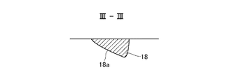
図3は、図2に示すIII−III線で切断した、フラップ18の前後方向の断面を示す断面図である。図3に示すように、フラップ18は、前後方向に前方から後方に向かって車体下部から遠ざかる傾斜面18aを備える。すなわち、フラップ18は、前後方向に前方から後方に向かって、その高さが増大する傾斜形状を有する。
FIG. 3 is a cross-sectional view showing a cross-section in the front-rear direction of the
このように構成されたフラップ18は、前方からの走行風を整流することで良好な空力特性を得るとともに、走行風を幅方向へと整流する。
The
なお、本発明において、フラップ18は、少なくとも、車体の下方側に突出し、かつ、幅方向に延在する部材であり、走行風を幅方向へと整流することができれば、上述の形状に限定されない。例えば、フラップ18は、車体の下方側に突出する板状の部材でもよいし、半円筒状の部材でもよいし、三角柱状の部材でもよい。
In the present invention, the
整流板20は、フラップ18に対して幅方向の内側位置に離間して形成されている。また、整流板20は、フラップ18と前後方向における略同一の位置に形成されている。また、整流板20は、タイヤ収納部14よりも幅方向の内側位置に形成されている。
The rectifying
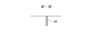
図4は、図2に示すIV−IV線で切断した、整流板20の前後方向の断面を示す断面図である。図4に示すように整流板20は、車体の下方側に突出し、かつ、幅方向に延在する板状の部材である。
FIG. 4 is a cross-sectional view showing a cross section in the front-rear direction of the rectifying
このように構成された整流板20は、前方からの走行風を幅方向へと整流する。
The rectifying
なお、本発明において、フラップ18は、少なくとも、下方側に突出し、かつ、幅方向に延在する部材であり、走行風を幅方向へと整流することができれば、上述の形状に限定されない。例えば、整流板20は、フラップ18と同様の傾斜面18aを有する形状でもよいし、半円筒状の部材でもよいし、三角柱状の部材でもよい。
In the present invention, the
第1の縦壁22は、フラップ18に対して前後方向の後方側、かつ、タイヤ収納部14に対して幅方向の内側位置に形成されている。また、本実施形態では、第1の縦壁22は、フラップ18よりも幅方向の内側位置に形成されている。
The first
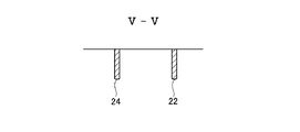
図5は、図2に示すV−V線で切断した、第1の縦壁22及び第2の縦壁24の幅方向の断面を示す断面図である。図5に示すように、第1の縦壁22は、車体の下方側に突出し、かつ、前後方向に延在する板状の部材である。さらに、第1の縦壁22は、その前後方向における後端部が、タイヤ収納部14の前後方向における後端部よりも後方に位置するように形成されている。
FIG. 5 is a cross-sectional view showing a cross section in the width direction of the first
第2の縦壁24は、整流板20に対して前後方向の後方側位置に、第1の縦壁22に対向して形成されている。また、本実施形態では、第2の縦壁24は、整流板よりも車体の幅方向の外側位置に形成されている。
The second
この第2の縦壁24は、図5に示すように、車体の下方側に突出し、かつ、前後方向に延在する板状の部材である。さらに、第2の縦壁24は、その前後方向における後端部が、タイヤ収納部14の前後方向における後端部よりも後方に位置するように形成されている。
As shown in FIG. 5, the second
第1の縦壁22と第2の縦壁24とは対向して、略平行となるように配置されており、前方から後方へと流れる気流の流路を形成している。
The first
なお、第1の縦壁22及び第2の縦壁24は、それぞれ、車体の下方側に突出し、対向して配置されており、気流の流路を形成することができれば、その形状を特に制限されない。例えば、第1の縦壁22及び第2の縦壁24は、半円筒状の部材でもよいし、三角柱状の部材でもよい。
Note that the first
なお、フラップ18と第1の縦壁22とは、第1の接続部26によって接続されている。第1の接続部26は、車体の下方側に突出した板状の部材である。また、第1の接続部26は、幅方向の内側に向かって凸の湾曲形状を有し、フラップ18と第1の縦壁22とを滑らかに接続している。
The
また、整流板20と第2の縦壁24とは、第2の接続部28によって接続されている。第2の接続部28は、車体の下方側に突出した板状の部材である。また、第2の接続部28は、幅方向の外側に向かって凸の湾曲形状を有し、整流板20と第2の縦壁24とを滑らかに接続している。
The rectifying
第1の接続部26と第2の接続部28とは、前方から後方へと向かって、その幅方向の離間距離が徐々に小さくなるように対向して配置されている。このように配置された第1の接続部26及び第2の接続部28は、前後方向にフラップ18から第1の縦壁22(整流板20から第2の縦壁24の)間で、気流の流路を形成している。この、第1の接続部26と第2の接続部28とによって形成された流路は、前方から後方に向かって徐々に幅が小さくなっている。
The
上述のフラップ18と、整流板20と、第1の縦壁22と、第2の縦壁24と、第1の接続部26と、第2の接続部28とは、車体下部を形成するアンダーカバーと別部材であってもよいし、アンダーカバーと一体に形成されていてもよい。
The
このように構成された車体構造16において、フラップ18及び整流板20によって幅方向に整流された走行風は、離間して配置されたフラップ18と整流板20との間の空間に流れ込む。この空間に流れ込んだ走行風は、広い空間から狭い空間へと流れ込むことになるので、後方に向かって加速される。すなわち、フラップ18及び整流板20は、その間に後方に向かう気流を発生させるとともに、この気流を後方に向かって加速させることができる。さらに、フラップ18及び整流板20は、前方からの走行風を整流して、その間を後方に向かう気流に変えることにより、タイヤ収納部14の内部に流入する走行風を低減することができる。
In the
そして、加速された気流は、第1の接続部26と第2の接続部28とによって形成された流路に流れ込む。この流路は、前方から後方に向かって徐々に幅が小さくなっている。したがって、この流路に流れ込んだ気流は、前方から後方に向かうにつれてさらに加速される。すなわち、第1の接続部26及び第2の接続部28は、その間を流れる気流を後方に向かってさらに加速させることができる。
Then, the accelerated airflow flows into the flow path formed by the
このように、走行風は、フラップ18及び整流板20によって整流されて、フラップ18及び整流板20の間を通過する気流となる。この気流は、フラップ18及び整流板20の間を通過したのち、第1の接続部26と第2の接続部28とによって形成された流路を通過することにより、後方に向かって加速される。
In this way, the traveling wind is rectified by the
さらに、加速された気流は、第1の縦壁22と第2の縦壁24とによって形成された流路を、その流れを維持したまま通過する。すなわち、第1の縦壁22及び第2の縦壁24は、後方に向かって流れる気流を、その流れを維持させたまま、タイヤ収納部14に沿って後方に向って確実に流すことができる。
Further, the accelerated airflow passes through the flow path formed by the first
さらに、形成された気流は、周囲の空気を吸引しながら後方に向かって流れる。特に、タイヤ収納部14の周囲の空気を吸引しながら後方に向かって流れる。より具体的には、フラップ18の後方、かつ、第1の接続部26の幅方向の外側位置周辺の空気を吸引することにより、タイヤ収納部14の前方位置から気流の流路に向かう、新たな気流を形成することができる。これにより、タイヤ収納部14の内部に流入する走行風をより一層低減することができるのである。
Further, the formed airflow flows backward while sucking ambient air. In particular, the air flows backward while sucking the air around the
また、本実施形態の車体構造16によれば、上述のようにタイヤ収納部14に流入する走行風の量を低減することができるので、タイヤ収納部14内部において乱気流の発生を抑制して、空気抵抗を低減し、空力性能を改善することができる。さらに、この空力性能の改善によって、更なる燃費の向上を図ることができる。
Further, according to the
以上、本実施形態の車体構造16について詳細に説明した。本発明は以上の実施形態に限定されるものではなく、様々な変化した構造、構成を採用してもよい。
The
例えば、上記実施形態では、車体構造16は、前方のタイヤ12及びタイヤ収納部14の周辺に設けられているとしたが、本発明はこれに限定されず、後方のタイヤ12及びタイヤ収納部14の周辺に設けられてもよい。これにより、後方のタイヤ12及びタイヤ収納部14の周囲においても、空力性能を改善することができる。さらに、この空力性能の改善によって、更なる燃費の改善を図ることができる。
For example, in the above-described embodiment, the
また、上記実施形態では、第1の縦壁22と第2の縦壁24とが略平行となるように配置されているとしたが、本発明はこれに限定されない。例えば、第1の縦壁と第2の縦壁との離間距離が、後方に向かうにつれて徐々に小さくなるようにしてもよい。すなわち、第1の縦壁22と第2の縦壁24とによって形成される流路が、後方に向かうにつれて徐々に狭くなるように構成されてもよい。これにより、この流路を流れる気流を、後方に向かうにつれて更に加速させることができる。また、さらに加速させることにより、タイヤ収納部14に流入する走行風の量をより一層低減することができ、空力性能を改善することができ、より一層の燃費の改善を図ることができる。
In the above embodiment, the first
また、上記実施形態では、第1の縦壁22及び第2の縦壁24の両方の後端部が、タイヤ収納部14の後端部よりも後方になるように形成されているとしたが本発明はこれに限定されない。第1の縦壁22及び第2の縦壁24の少なくとも一方の後端部が、タイヤ収納部14の後端部と、前後方向に略同じ位置か、又は、後方になるように形成されていてもよい。このように構成されている場合であっても、発生させた気流をタイヤ収納部14よりも後方に確実に流すことができる。これにより、気流がタイヤ収納部14に流入することを防止することができる。
In the above embodiment, the rear end portions of both the first
<実施形態の構成及び効果>
以上の実施形態によれば、タイヤ12を収納するタイヤ収納部14と、車体の下面のタイヤ収納部14に対して幅方向の内側近傍位置に、他の部分よりも流速が早い領域を作成可能な流速加速手段と、を有する。
このような構成によって、前方からの走行風の一部をタイヤ収納部14の近傍位置において加速させて、他の部分よりも流速が早い領域を作成できる。さらに、加速された気流は、周囲の空気を吸引しながら後方に向かって流れる。タイヤ収納部14の周辺から内側位置に向かう気流を形成することができる。これにより、タイヤ収納部14の内部に流入する走行風を低減することができる。
また、タイヤ収納部14に流入する走行風の量を低減することができるので、タイヤ収納部14内部において乱気流の発生を抑制して、空気抵抗を低減し、空力性能を改善することができる。さらに、この空力性能の改善によって、更なる燃費の改善を図ることができる。
<Configuration and Effect of Embodiment>
According to the above embodiment, it is possible to create a region where the flow velocity is faster than the other portions in the
With such a configuration, a part of the traveling wind from the front can be accelerated in the vicinity of the
Further, since the amount of traveling wind flowing into the
さらに、以上の実施形態によれば、流速加速手段は、タイヤ収納部14に対して幅方向の内側位置に形成され、車体の下方側に突出し、かつ、前後方向に延在する第1の縦壁22と、第1の縦壁22に対向する位置に形成され、車体の下方側に突出し、かつ、前後方向に延在する第2の縦壁24と、を備える。
このような構成によって、前方からの走行風の一部をタイヤ収納部14の近傍位置において加速させて、他の部分よりも流速が早い領域を作成できる。さらに、加速された気流は、周囲の空気を吸引しながら後方に向かって流れる。タイヤ収納部14の周辺から内側位置に向かう気流を形成することができる。これにより、タイヤ収納部14の内部に流入する走行風を低減することができる。また、後方に向かって流れる気流を、その流れを維持させたまま、タイヤ収納部14に沿って後方に向って確実に流すことができる。
Furthermore, according to the above embodiment, the flow velocity accelerating means is formed at the inner position in the width direction with respect to the
With such a configuration, a part of the traveling wind from the front can be accelerated in the vicinity of the
さらに、以上の実施形態によれば、流速加速手段は、第1の縦壁22に対して前後方向の前方側、及び、幅方向の外側位置、並びに、タイヤ収納部14に対して前後方向の前方側位置に形成され、車体の下方側に突出し、かつ、車体の幅方向に延在するフラップ18を備える。
このような構成によって、前方からの走行風を幅方向に整流することができ、第1の縦壁と第2の縦壁との間に流れ込む気流を発生させることができる。また、前方からの走行風を幅方向に整流することができ、タイヤ収納部14に流入する走行風を一層低減させることができる。
Furthermore, according to the above embodiment, the flow velocity accelerating means is located in the front side in the front-rear direction and the outer position in the width direction with respect to the first
With such a configuration, the traveling wind from the front can be rectified in the width direction, and an airflow flowing between the first vertical wall and the second vertical wall can be generated. Moreover, the traveling wind from the front can be rectified in the width direction, and the traveling wind flowing into the
さらに、以上の実施形態によれば、流速加速手段は、フラップ18と第1の縦壁22とを滑らかに接続する第1の接続部26を備える。
このような構成によって、フラップ18から第1の縦壁22に向かって気流を確実に流すことができる。
Furthermore, according to the above embodiment, the flow velocity accelerating means includes the first connecting
With such a configuration, it is possible to reliably flow airflow from the
さらに、以上の実施形態によれば、流速加速手段は、第2の縦壁24に対して前後方向の前方側、かつ、幅方向の内側位置に形成され、車体の下方側に突出し、かつ、幅方向に延在する整流板20を備える。
このような構成によって、前方からの走行風を幅方向に整流することができ、第1の縦壁と第2の縦壁との間に流れ込む気流を発生させることができる。
特に、フラップ18と整流板20とを備える場合、その間に後方に向かう気流を発生させるとともに、この気流を後方に向かって加速させることができる。さらに、形成された気流は、周囲の空気を吸引しながら後方に向かって流れる。特に、フラップ18の後方の空気を吸引することにより、タイヤ収納部14の前方位置から内側位置に向かう気流を形成することができる。これにより、タイヤ収納部14の内部に流入する走行風をより一層低減することができる。
Furthermore, according to the above embodiment, the flow velocity accelerating means is formed at the front side in the front-rear direction and the inner side in the width direction with respect to the second
With such a configuration, the traveling wind from the front can be rectified in the width direction, and an airflow flowing between the first vertical wall and the second vertical wall can be generated.
In particular, when the
さらに、以上の実施形態によれば、流速加速手段は、整流板20と第2の縦壁24とを滑らかに接続する第2の接続部28を備える。
このような構成によって、整流板20から第2の縦壁24に向かって気流を確実に流すことができる。
特に、第1の接続部26と第2の接続部28とを備えることにより、第1の接続部26及び第2の接続部28の間を流れる走向風を後方に向かってさらに加速させることができる。
Furthermore, according to the above embodiment, the flow velocity accelerating means includes the
With such a configuration, it is possible to reliably flow airflow from the rectifying
In particular, by providing the first connecting
なお、以上の実施形態によれば、第1の縦壁22は、フラップ18に対して幅方向の内側位置に形成され、第2の縦壁24は、整流板20に対して車体の幅方向の外側位置に形成される。
このような構成によって、フラップ18及び整流板20によって形成された気流を、さらに絞ることにより減速させることなく、後方に向かって流すことができる。
According to the above embodiment, the first
With such a configuration, the airflow formed by the
さらに、以上の実施形態によれば、第1の縦壁22及び第2の縦壁24の少なくとも一方は、前後方向における後端部が、タイヤ収納部14の前後方向の後端部と、前後方向に略同じ位置か、又は、後方になるように形成される。
このような構成によって、発生させた気流をタイヤ収納部14よりも後方に確実に流すことができる。これにより、気流がタイヤ収納部14に流入することを防止することができる。
Furthermore, according to the above embodiment, at least one of the first
With such a configuration, the generated airflow can be reliably flowed behind the
さらに、以上の実施形態によれば、第1の縦壁22と第2の縦壁24との幅方向の離間距離が、前方から後方に向かって小さくなる。
このような構成により、第1の縦壁22と第2の縦壁24とによって形成される流路が、後方に向かうにつれて徐々に狭くなる。これにより、この流路を流れる気流を、後方に向かうにつれて更に加速させることができる。また、さらに加速させることにより、タイヤ収納部14に流入する走行風の量をより一層低減させることができ、空力性能を改善することができ、より一層の燃費の改善を図ることができる。
Furthermore, according to the above embodiment, the separation distance in the width direction between the first
With such a configuration, the flow path formed by the first
また、以上の実施形態によれば、タイヤ12を収納するタイヤ収納部14と、タイヤ収納部14に対して前後方向の前方側位置に形成され、車両10の下方側に突出し、かつ、幅方向に延在するフラップ18と、タイヤ収納部14よりも幅方向の内側位置に、フラップ18に対して幅方向の内側位置に離間して形成され、車両10の下方側に突出し、かつ、幅方向に延在する整流板20と、を有する。
Moreover, according to the above embodiment, it is formed in the
このような構成によって、前方からの走行風を幅方向に整流することができ、タイヤ収納部14に流入する走行風を低減させることができる。
また、離間して配置されたフラップ18と整流板20により、その間に後方に向かう気流を発生させるとともに、この気流を後方に向かって加速させることができる。
さらに、形成された気流は、周囲の空気を吸引しながら後方に向かって流れる。特に、フラップ18の後方の空気を吸引することにより、タイヤ収納部14の前方位置から内側位置に向かう気流を形成することができる。これにより、タイヤ収納部14の内部に流入する走行風をより一層低減することができる。
また、タイヤ収納部14に流入する走行風の量を低減することができるので、タイヤ収納部14内部において乱気流の発生を抑制して、空気抵抗を低減し、空力性能を改善することができる。さらに、この空力性能の改善によって、更なる燃費の改善を図ることができる。
With such a configuration, traveling wind from the front can be rectified in the width direction, and traveling wind flowing into the
Further, the
Further, the formed airflow flows backward while sucking ambient air. In particular, by sucking the air behind the
Further, since the amount of traveling wind flowing into the
さらに、以上の実施形態によれば、フラップ18と整流板20とは、前後方向における略同一の位置に形成される。
このような構成によって、その間に後方に向かう気流をより好適に発生させるとともに、この気流を後方に向かってより好適に加速させることができる。
Furthermore, according to the above embodiment, the
With such a configuration, it is possible to more suitably generate an airflow toward the rear in the meantime and to accelerate the airflow more favorably toward the rear.
<定義>
流速加速手段の一例が、第1の壁、第2の壁、フラップ、整流板、第1の接続部、第2の接続部である。なお、流速加速手段は、以上の全ての部材を有しなくてもよいことはいうまでもない。
<Definition>
An example of the flow velocity accelerating means is a first wall, a second wall, a flap, a current plate, a first connection part, and a second connection part. Needless to say, the flow velocity accelerating unit does not have to include all of the above members.
10 車両
12 タイヤ
14 タイヤ収納部
16 車体構造
18 フラップ
20 整流板
22 第1の縦壁
24 第2の縦壁
26 第1の接続部
28 第2の接続部
DESCRIPTION OF
Claims (10)
前記車体の下面の前記タイヤ収納部に対して前記車体の幅方向の内側近傍位置に、他の部分よりも流速が早い領域を作成可能な流速加速手段と、を有する
車体構造。 A tire storage part that is formed on a part of the vehicle body and stores a tire;
A vehicle body structure having flow velocity accelerating means capable of creating a region where the flow velocity is higher than other portions at a position near the inner side in the width direction of the vehicle body with respect to the tire storage portion on the lower surface of the vehicle body.
前記第1の縦壁に対向する位置に形成され、前記車体の下方側に突出し、かつ、前記車体の前後方向に延在する第2の縦壁と、を備える
請求項1に記載の車体構造。 The flow velocity accelerating means is formed at an inner position in the width direction of the vehicle body with respect to the tire storage portion, protrudes to the lower side of the vehicle body, and extends in the front-rear direction of the vehicle body. ,
The vehicle body structure according to claim 1, further comprising: a second vertical wall that is formed at a position facing the first vertical wall, protrudes downward from the vehicle body, and extends in the front-rear direction of the vehicle body. .
請求項2に記載の車体構造。 The flow velocity accelerating means includes a front side in the front-rear direction of the vehicle body with respect to the first vertical wall, an outer position in the width direction of the vehicle body, and a position in the front-rear direction of the vehicle body with respect to the tire storage portion. The vehicle body structure according to claim 2, further comprising a flap that is formed at a front side position, protrudes downward from the vehicle body, and extends in a width direction of the vehicle body.
請求項3に記載の車体構造。 The vehicle body structure according to claim 3, wherein the flow velocity accelerating means includes a first connection portion that smoothly connects the flap and the first vertical wall.
請求項2〜4のいずれかに記載の車体構造。 The flow velocity accelerating means is formed on the front side in the front-rear direction of the vehicle body and on the inner side in the width direction of the vehicle body with respect to the second vertical wall, protrudes below the vehicle body, and the vehicle body The vehicle body structure according to any one of claims 2 to 4, further comprising a current plate extending in a width direction.
請求項5に記載の車体構造。 The vehicle body structure according to claim 5, wherein the flow velocity accelerating means includes a second connection portion that smoothly connects the rectifying plate and the second vertical wall.
請求項2〜6のいずれかに記載の車体構造 At least one of the first vertical wall and the second vertical wall has a rear end portion in the front-rear direction of the vehicle body that is substantially in the front-rear direction and the rear end portion in the front-rear direction of the vehicle body of the tire storage portion. The vehicle body structure according to any one of claims 2 to 6, wherein the vehicle body structure is formed at the same position or at the rear.
請求項2〜7のいずれかに記載の車体構造。 The vehicle body structure according to any one of claims 2 to 7, wherein a separation distance in a width direction of the vehicle body between the first vertical wall and the second vertical wall decreases from the front to the rear of the vehicle body.
前記タイヤ収納部よりも前記車体の幅方向の内側位置に、前記フラップに対して前記車体の幅方向の内側位置に離間して形成され、前記車体の下方側に突出し、かつ、前記車体の幅方向に延在する整流板と、の少なくとも一方を備える
請求項1に記載の車体構造。 The flow velocity accelerating means is formed at a front side position in the front-rear direction of the vehicle body with respect to the tire storage part, protrudes to the lower side of the vehicle body, and extends in the width direction of the vehicle body,
It is formed at an inner position in the width direction of the vehicle body than the tire storage portion, spaced apart from an inner position in the width direction of the vehicle body with respect to the flap, and protrudes to the lower side of the vehicle body, and the width of the vehicle body The vehicle body structure according to claim 1, comprising at least one of a current plate extending in a direction.
請求項9に記載の車体構造。 The vehicle body structure according to claim 9, wherein the flap and the current plate are formed at substantially the same position in the front-rear direction of the vehicle body.
Priority Applications (1)
| Application Number | Priority Date | Filing Date | Title |
|---|---|---|---|
| JP2011146483A JP5879056B2 (en) | 2011-06-30 | 2011-06-30 | Body structure |
Applications Claiming Priority (1)
| Application Number | Priority Date | Filing Date | Title |
|---|---|---|---|
| JP2011146483A JP5879056B2 (en) | 2011-06-30 | 2011-06-30 | Body structure |
Publications (2)
| Publication Number | Publication Date |
|---|---|
| JP2013014165A true JP2013014165A (en) | 2013-01-24 |
| JP5879056B2 JP5879056B2 (en) | 2016-03-08 |
Family
ID=47687299
Family Applications (1)
| Application Number | Title | Priority Date | Filing Date |
|---|---|---|---|
| JP2011146483A Active JP5879056B2 (en) | 2011-06-30 | 2011-06-30 | Body structure |
Country Status (1)
| Country | Link |
|---|---|
| JP (1) | JP5879056B2 (en) |
Cited By (2)
| Publication number | Priority date | Publication date | Assignee | Title |
|---|---|---|---|---|
| JP2017013710A (en) * | 2015-07-03 | 2017-01-19 | 富士重工業株式会社 | Engine room cooling structure |
| JP2017065445A (en) * | 2015-09-30 | 2017-04-06 | 富士重工業株式会社 | Air flow guide structure |
Citations (5)
| Publication number | Priority date | Publication date | Assignee | Title |
|---|---|---|---|---|
| DE3410296A1 (en) * | 1984-03-21 | 1985-09-26 | Herwig 4156 Willich Fischer | Device for improving the grip of vehicles |
| JPS63139182U (en) * | 1987-03-06 | 1988-09-13 | ||
| FR2863244A1 (en) * | 2003-12-09 | 2005-06-10 | Peugeot Citroen Automobiles Sa | Streamlined device for motor vehicle, has plates extending parallely on both sides of longitudinal median plane of motor vehicle, and placed vertically beneath base of vehicle |
| WO2009105631A2 (en) * | 2008-02-21 | 2009-08-27 | Dayton Roderick M | System for reducing aerodynamic drag on vehicles |
| DE102008039495A1 (en) * | 2008-08-23 | 2010-02-25 | Bayerische Motoren Werke Aktiengesellschaft | Cover elements e.g. laminar underbody covers, for underbody of motor vehicle i.e. car, have elongated recess and/or elevation that runs in direction of air flow, where air flow is self-adjustable in underbody during drive of motor vehicle |
-
2011
- 2011-06-30 JP JP2011146483A patent/JP5879056B2/en active Active
Patent Citations (5)
| Publication number | Priority date | Publication date | Assignee | Title |
|---|---|---|---|---|
| DE3410296A1 (en) * | 1984-03-21 | 1985-09-26 | Herwig 4156 Willich Fischer | Device for improving the grip of vehicles |
| JPS63139182U (en) * | 1987-03-06 | 1988-09-13 | ||
| FR2863244A1 (en) * | 2003-12-09 | 2005-06-10 | Peugeot Citroen Automobiles Sa | Streamlined device for motor vehicle, has plates extending parallely on both sides of longitudinal median plane of motor vehicle, and placed vertically beneath base of vehicle |
| WO2009105631A2 (en) * | 2008-02-21 | 2009-08-27 | Dayton Roderick M | System for reducing aerodynamic drag on vehicles |
| DE102008039495A1 (en) * | 2008-08-23 | 2010-02-25 | Bayerische Motoren Werke Aktiengesellschaft | Cover elements e.g. laminar underbody covers, for underbody of motor vehicle i.e. car, have elongated recess and/or elevation that runs in direction of air flow, where air flow is self-adjustable in underbody during drive of motor vehicle |
Cited By (2)
| Publication number | Priority date | Publication date | Assignee | Title |
|---|---|---|---|---|
| JP2017013710A (en) * | 2015-07-03 | 2017-01-19 | 富士重工業株式会社 | Engine room cooling structure |
| JP2017065445A (en) * | 2015-09-30 | 2017-04-06 | 富士重工業株式会社 | Air flow guide structure |
Also Published As
| Publication number | Publication date |
|---|---|
| JP5879056B2 (en) | 2016-03-08 |
Similar Documents
| Publication | Publication Date | Title |
|---|---|---|
| JP6288016B2 (en) | Rectification structure for vehicles | |
| JP5983568B2 (en) | Vehicle lower structure | |
| JP5303598B2 (en) | Body side structure | |
| JP5983384B2 (en) | Car body rear structure | |
| WO2012169322A1 (en) | Structure for rear portion of vehicle | |
| JP2009090681A (en) | Vehicle substructure | |
| JP2012126178A (en) | Rear spoiler | |
| JP2011057147A (en) | Vehicle lower part structure | |
| JP5686106B2 (en) | Lower body structure of the vehicle | |
| JP5831410B2 (en) | Vehicle front structure | |
| JP2009029334A (en) | Lower part structure of vehicle body | |
| JP6326884B2 (en) | Vehicle door mirror | |
| JP5879056B2 (en) | Body structure | |
| JP2007253656A (en) | Deflector structure of vehicle | |
| JP2015209121A (en) | Traveling wind guide structure of automobile | |
| JP2017071289A (en) | Car body side part structure | |
| JP6378996B2 (en) | Vehicle structure | |
| JP6191550B2 (en) | Aerodynamic structure for vehicles | |
| JP2014226953A (en) | Cooling structure of drive unit in wheel | |
| JP2017071288A (en) | Car body lower part structure | |
| JP5820641B2 (en) | Body structure | |
| JP2021147005A (en) | Vehicle with improved aerodynamic characteristic | |
| JP5419946B2 (en) | Vehicle front structure | |
| JP7328949B2 (en) | Air guide structure for vehicle and air guide forming member | |
| JP2014054958A (en) | Vehicle lower part structure |
Legal Events
| Date | Code | Title | Description |
|---|---|---|---|
| A621 | Written request for application examination |
Free format text: JAPANESE INTERMEDIATE CODE: A621 Effective date: 20140512 |
|
| A977 | Report on retrieval |
Free format text: JAPANESE INTERMEDIATE CODE: A971007 Effective date: 20150525 |
|
| A131 | Notification of reasons for refusal |
Free format text: JAPANESE INTERMEDIATE CODE: A131 Effective date: 20150602 |
|
| A521 | Request for written amendment filed |
Free format text: JAPANESE INTERMEDIATE CODE: A523 Effective date: 20150722 |
|
| TRDD | Decision of grant or rejection written | ||
| A01 | Written decision to grant a patent or to grant a registration (utility model) |
Free format text: JAPANESE INTERMEDIATE CODE: A01 Effective date: 20160105 |
|
| A61 | First payment of annual fees (during grant procedure) |
Free format text: JAPANESE INTERMEDIATE CODE: A61 Effective date: 20160201 |
|
| R150 | Certificate of patent or registration of utility model |
Ref document number: 5879056 Country of ref document: JP Free format text: JAPANESE INTERMEDIATE CODE: R150 |
|
| S533 | Written request for registration of change of name |
Free format text: JAPANESE INTERMEDIATE CODE: R313533 |
|
| R350 | Written notification of registration of transfer |
Free format text: JAPANESE INTERMEDIATE CODE: R350 |
|
| R250 | Receipt of annual fees |
Free format text: JAPANESE INTERMEDIATE CODE: R250 |
|
| R250 | Receipt of annual fees |
Free format text: JAPANESE INTERMEDIATE CODE: R250 |
|
| R250 | Receipt of annual fees |
Free format text: JAPANESE INTERMEDIATE CODE: R250 |
|
| R250 | Receipt of annual fees |
Free format text: JAPANESE INTERMEDIATE CODE: R250 |
|
| R250 | Receipt of annual fees |
Free format text: JAPANESE INTERMEDIATE CODE: R250 |
|
| R250 | Receipt of annual fees |
Free format text: JAPANESE INTERMEDIATE CODE: R250 |