JP2013010177A - Head detachable type cutting tool - Google Patents
Head detachable type cutting tool Download PDFInfo
- Publication number
- JP2013010177A JP2013010177A JP2012192878A JP2012192878A JP2013010177A JP 2013010177 A JP2013010177 A JP 2013010177A JP 2012192878 A JP2012192878 A JP 2012192878A JP 2012192878 A JP2012192878 A JP 2012192878A JP 2013010177 A JP2013010177 A JP 2013010177A
- Authority
- JP
- Japan
- Prior art keywords
- groove
- taper
- shaft portion
- tapered
- shank
- Prior art date
- Legal status (The legal status is an assumption and is not a legal conclusion. Google has not performed a legal analysis and makes no representation as to the accuracy of the status listed.)
- Granted
Links
- 238000005520 cutting process Methods 0.000 title claims abstract description 94
- 230000002093 peripheral effect Effects 0.000 claims abstract description 14
- 238000009434 installation Methods 0.000 claims description 12
- 239000000463 material Substances 0.000 claims description 11
- 238000004804 winding Methods 0.000 claims description 6
- 238000003754 machining Methods 0.000 abstract description 9
- 230000000052 comparative effect Effects 0.000 description 8
- 238000012545 processing Methods 0.000 description 8
- 238000012360 testing method Methods 0.000 description 6
- 229910000831 Steel Inorganic materials 0.000 description 5
- 238000011156 evaluation Methods 0.000 description 5
- 238000005259 measurement Methods 0.000 description 5
- 239000010959 steel Substances 0.000 description 5
- 238000003801 milling Methods 0.000 description 3
- 230000003746 surface roughness Effects 0.000 description 3
- 229910000639 Spring steel Inorganic materials 0.000 description 2
- 229910003460 diamond Inorganic materials 0.000 description 2
- 239000010432 diamond Substances 0.000 description 2
- 230000000694 effects Effects 0.000 description 2
- 230000013011 mating Effects 0.000 description 2
- 238000000034 method Methods 0.000 description 2
- 230000002265 prevention Effects 0.000 description 2
- 229910000997 High-speed steel Inorganic materials 0.000 description 1
- 238000013459 approach Methods 0.000 description 1
- 238000007796 conventional method Methods 0.000 description 1
- 239000013078 crystal Substances 0.000 description 1
- 238000010586 diagram Methods 0.000 description 1
- 238000005553 drilling Methods 0.000 description 1
- 238000003780 insertion Methods 0.000 description 1
- 230000037431 insertion Effects 0.000 description 1
- 238000004519 manufacturing process Methods 0.000 description 1
- 102220005308 rs33960931 Human genes 0.000 description 1
Images


Landscapes
- Milling Processes (AREA)
- Drilling Tools (AREA)
- Milling, Broaching, Filing, Reaming, And Others (AREA)
Abstract
Description
この発明は、切れ刃を有する切削ヘッドを工夫された継手を用いてシャンク部に着脱自在に締結するヘッド着脱式切削工具に関する。 The present invention relates to a head detachable cutting tool for detachably fastening a cutting head having a cutting edge to a shank portion using a devised joint.
首記の切削工具の従来技術として、例えば、下記特許文献1〜4に開示されたものがある。
Examples of the prior art of the above-mentioned cutting tools include those disclosed in
特許文献1の切削工具(ボールエンドミル)は、エンドミルヘッドとシャンクとその両者にねじ込まれるプルロッドとで構成され、エンドミルヘッドとシャンクが工具中心軸に対してほぼ垂直な突き合わせ面を含み、このエンドミルヘッドとシャンクを、前記プルロッドで互いに引き寄せ、前記突き合わせ面を互いに突き合わせて締結する。
The cutting tool (ball end mill) of
また、特許文献2の切削工具(フライス工具)は、切削ヘッドとシャンクと保持手段とで構成され、シャンク先端のテーパ穴に挿入した保持手段をシャンクにねじ込み、テーパ穴との嵌合部の作用で保持手段を切削ヘッドに係合させてその切削ヘッドを前記テーパ穴に引き込み、シャンクにテーパ嵌合させて切削ヘッドをシャンクに締結する。
Moreover, the cutting tool (milling tool) of
特許文献3の刃部交換式切削工具も、特許文献2のフライス工具とほぼ同様の構造である。刃部に係合させた固定用部材を工具本体の先端に設けられた挿入孔に挿入して工具本体にねじ込むことで刃部を工具本体側に引き寄せ、刃部の突き合わせ面を工具本体の先端にテーパ嵌合させて刃部を工具本体に締結する。
The blade part exchangeable cutting tool of
さらに、特許文献4の切削工具は、切削ヘッドに相当する雄の部材に締結用の雄ねじを形成し、その雄ねじをシャンクに相当する雌の部材の雌ねじ(ねじ孔)にねじ込んで雄の部材を雌の部材に締結する。雄ねじは工具継手の長さ短縮や強度維持を図るために不完全ねじ部の含まれないねじにしており、締結完了位置で雄の部材のショルダー面(軸方向端面)が雌の部材の先端に突き当たり、同時に、雄の部材の雄ねじの根元部分が雌の部材のねじ孔の入口部にテーパ嵌合する。
Further, in the cutting tool of
特許文献1の切削工具は、プルロッドをシャンクの後端側から操作してエンドミルヘッドに引き込み力を伝達するので、着脱の操作性が良くない。また、シャンクを加工機に装着したままでエンドミルヘッドを交換する所謂機上での交換ができず、使い勝手も悪い。
Since the cutting tool of
さらに、エンドミルヘッドの拘束を、プルロッドのシャンクに対するねじ嵌合や円筒嵌合、エンドミルヘッドに対するテーパ嵌合、エンドミルヘッドとシャンクの軸方向端面(突合せ面)の突き合わせなどを組み合わせて行なっている。所謂3面拘束の構造であり、そのために、刃振れの高精度管理を行なう場合、高い加工精度が要求され、生産性の低下、コストアップが避けられない。 Further, the end mill head is constrained by a combination of screw fitting or cylindrical fitting of the pull rod to the shank, taper fitting of the end mill head, butting of the end face in the axial direction (butting surface) of the end mill head and the shank. This is a so-called three-surface constrained structure. For this reason, when high-precision management of blade runout is performed, high machining accuracy is required, and reduction in productivity and increase in cost are inevitable.
また、雄ねじ、雌ねじが全面で密着するようなねじ嵌合部は加工が極めて難しいことから、ねじ嵌合部での拘束では、不可避の加工誤差による密着不良箇所(図14、図15の隙間g)が生じ、精度や締結信頼性の確保が不十分になり易い。なお、図14は従来方法でのねじのみによる締結、図15はテーパ面とねじを併用した締結を表している。 Further, since it is extremely difficult to process the screw fitting portion where the male screw and the female screw are in close contact with each other, in the restraint at the screw fitting portion, an inadequate contact portion due to an inevitable processing error (gap g in FIGS. 14 and 15). ) Occurs, and accuracy and fastening reliability are likely to be insufficient. FIG. 14 shows fastening using only a screw in the conventional method, and FIG. 15 shows fastening using both a tapered surface and a screw.
特許文献2,3の切削工具も、特許文献1の工具と同様の問題点を有している。また、保持手段(刃部固定用部材)に設けられた係止用の突部をテーパ面の作用を利用して切削ヘッド(刃部)に係合させるので係止部の接触面積が必然的に小さくなり、高負荷切削での締結保持の信頼性が低い。
The cutting tools of
また、特許文献4の切削工具は、雄ねじと雌ねじから成る工具継手の有効嵌合面積が小さく、接続部の緩み止めの信頼性に欠ける。また、雄の部材と雌の部材のテーパ嵌合面の嵌合領域が極めて小さいため、特に軸直角方向の負荷に耐える能力が小さく、高負荷切削では雄の部材が動いて高加工精度の確保が難しい。
Moreover, the cutting tool of
この発明は、着脱の操作性や使い勝手に優れ、しかも、高い加工精度を必要としない構造で着脱式切削工具の強固かつ信頼性の高い締結を可能となすことを課題としている。 An object of the present invention is to enable a detachable cutting tool to be firmly and reliably fastened with a structure that is excellent in detachability operability and usability and does not require high machining accuracy.
上記の課題を解決するため、この発明においては、切削ヘッドと、シャンクと、弾性を有する螺旋コイル状の締結補助具とからなり、
前記切削ヘッドが、テーパ軸部と、そのテーパ軸部の外周に形成されたねじれ溝と、前記テーパ軸部の根元から径方向外側に張り出す平坦なショルダー面を後部に有し、
前記シャンクが前記ショルダー面を突き当てる前端面と、前記テーパ軸部を適合して受け入れる前記前端面に開口したテーパ孔と、前記テーパ軸部の外周のねじれ溝に対応させて前記テーパ孔の内面に形成されたねじれ溝を有し、
前記締結補助具が、前記テーパ軸部の外周のねじれ溝と前記テーパ孔の内面のねじれ溝との間に形成される空間と略相似形の断面形状を有し、
前記締結補助具が前記テーパ軸部の外周のねじれ溝と前記テーパ孔の内面のねじれ溝のいずれか一方に装着され、この状態で前記テーパ軸部が前記テーパ孔に挿入され、前記締結補助具が前記テーパ軸部の外周のねじれ溝と前記テーパ孔の内面のねじれ溝の双方に入り込んで双方のねじれ溝の溝面に弾性的に押しつけられ、
前記ショルダー面が前記シャンクの前端面に密着し、さらに、前記テーパ軸部の外周面が前記テーパ孔の内面に密着して前記切削ヘッドが前記シャンクに締結される着脱式切削工具を提供する。
In order to solve the above problems, the present invention comprises a cutting head, a shank, and a helical coil-shaped fastening aid having elasticity,
The cutting head has a taper shaft portion, a torsion groove formed on the outer periphery of the taper shaft portion, and a flat shoulder surface projecting radially outward from the base of the taper shaft portion at the rear portion,
A front end surface with which the shank abuts against the shoulder surface, a tapered hole opened in the front end surface for receiving the tapered shaft portion in conformity, and an inner surface of the tapered hole corresponding to a torsion groove on the outer periphery of the tapered shaft portion Having a twisted groove formed in
The fastening aid has a cross-sectional shape substantially similar to a space formed between a torsion groove on the outer periphery of the tapered shaft portion and a torsion groove on the inner surface of the taper hole,
The fastening aid is attached to one of a twist groove on the outer periphery of the taper shaft portion and a twist groove on the inner surface of the taper hole, and in this state, the taper shaft portion is inserted into the taper hole. Enters both the torsion groove on the outer periphery of the tapered shaft portion and the torsion groove on the inner surface of the taper hole, and is elastically pressed against the groove surfaces of both the torsion grooves,
Provided is a detachable cutting tool in which the shoulder surface is in close contact with the front end surface of the shank, and the outer peripheral surface of the tapered shaft portion is in close contact with the inner surface of the tapered hole so that the cutting head is fastened to the shank.
前記テーパ軸部の外周のねじれ溝と前記テーパ孔の内面のねじれ溝の設置ピッチは、テーパ軸部とテーパ孔をテーパ嵌合させるためにねじれ溝の溝幅よりも大きくしており、そのために、テーパ軸部の外周面とテーパ孔の内面が残存している。 The installation pitch of the torsion groove on the outer periphery of the taper shaft portion and the torsion groove on the inner surface of the taper hole is larger than the groove width of the torsion groove in order to taper-fit the taper shaft portion and the taper hole. The outer peripheral surface of the taper shaft portion and the inner surface of the taper hole remain.
この切削工具は、以下に列挙するものが好ましい。
(1)前記締結補助具がテーパの螺旋コイル状をなし、自由状態でのコイルの巻きピッチが前記ねじれ溝の設置ピッチよりも小さく、この締結補助具が引き伸ばされて前記テーパ軸部の外周のねじれ溝と前記テーパ孔の内面のねじれ溝のどちらか一方に装着されたもの。
(2)前記締結補助具が螺旋コイルの巻きピッチがねじれ溝の設置ピッチと等しくなるところまで前記締結補助具が引き伸ばされたときにこの締結補助具が前記テーパ軸部又は前記テーパ孔のテーパ角とほぼ等しいテーパ角を持つようにしたもの。(3)前記締結補助具が略平行四辺形の断面を有し、その断面の一方の組の対角コーナが螺旋コイルの内径側と外径側に配置されるもの。
(4)前記締結補助具が前記切れ刃の材質よりも軟質の材料、より好ましくは、鋼で形成されたもの。
(5)前記テーパ軸部の外周面と前記テーパ孔の内面の相互接触面積を、前記ねじれ溝が無い状態での相互接触面積との比で75%以上確保したもの。
(6)前記テーパ軸部の外周のねじれ溝と前記テーパ孔の内面のねじれ溝のねじれ角を75°以上、90°未満の範囲に設定したもの。
The cutting tools are preferably those listed below.
(1) The fastening aid has a tapered helical coil shape, and the winding pitch of the coil in a free state is smaller than the installation pitch of the torsion groove, and this fastening aid is stretched to extend the outer periphery of the tapered shaft portion. Mounted on either the twisted groove or the twisted groove on the inner surface of the tapered hole.
(2) When the fastening aid is stretched to a position where the winding pitch of the spiral coil becomes equal to the installation pitch of the torsion groove, the fastening aid becomes the taper angle of the tapered shaft portion or the tapered hole. With a taper angle approximately equal to (3) The fastening aid has a substantially parallelogram-shaped cross section, and one set of diagonal corners of the cross section is disposed on the inner diameter side and the outer diameter side of the spiral coil.
(4) The fastening aid is made of a material softer than the material of the cutting edge, more preferably steel.
(5) The contact area between the outer peripheral surface of the taper shaft portion and the inner surface of the taper hole is ensured by 75% or more in comparison with the mutual contact area without the twisted groove.
(6) The torsion angle of the torsion groove on the outer periphery of the tapered shaft portion and the torsion groove on the inner surface of the taper hole is set in a range of 75 ° or more and less than 90 °.
この発明の切削工具は、テーパ軸部の外周のねじれ溝とテーパ孔の内面のねじれ溝のどちらか一方に装着した螺旋コイル状の締結補助具をねじ山として機能させて切削ヘッドのテーパ軸部をシャンクのテーパ孔にねじ込む。そして、切削ヘッドに設けたショルダー面をシャンクの前端面に密着させ、同時に、切削ヘッドに設けたテーパ軸部の外周面をシャンクに設けたテーパ孔の内面に密着させる。 The cutting tool according to the present invention has a function in which a helical coil-shaped fastening auxiliary tool mounted on one of a torsion groove on the outer periphery of the taper shaft part and a torsion groove on the inner surface of the taper hole functions as a screw thread. Is screwed into the tapered hole of the shank. Then, the shoulder surface provided on the cutting head is brought into close contact with the front end surface of the shank, and at the same time, the outer peripheral surface of the taper shaft provided on the cutting head is brought into close contact with the inner surface of the tapered hole provided in the shank.
この構造によれば、高精度加工を要求される箇所がテーパ軸部とテーパ孔の嵌合面(テーパ軸部の外周面とテーパ孔の内面)のみとなり、刃振れの高精度管理が要求される場合の生産性の低下やコストアップの問題が解消される。 According to this structure, only the fitting surface of the taper shaft portion and the taper hole (the outer peripheral surface of the taper shaft portion and the inner surface of the taper hole) is required for high-precision machining, and high-precision management of blade runout is required. This eliminates the problem of lowering productivity and increasing costs.
また、切削ヘッドの径方向の位置決め(芯出し)が、広い嵌合面積を確保できるテーパ軸部とテーパ孔の嵌合部によってなされる。これに加えて、軸方向の位置決めと位置保持が、切削ヘッドに設けたショルダー面とシャンクの先端面の突き合わせ部によってなされ、そのために、切削ヘッドの位置保持の信頼性が高く、加工精度も向上する。 Further, the positioning (centering) of the cutting head in the radial direction is performed by the tapered shaft portion that can secure a wide fitting area and the fitting portion of the tapered hole. In addition to this, axial positioning and position holding are performed by the abutting portion between the shoulder surface provided on the cutting head and the tip surface of the shank. Therefore, the position holding position of the cutting head is highly reliable and the processing accuracy is also improved. To do.
さらに、締結補助具をねじ山として機能させて切削ヘッドのテーパ軸部をシャンクのテーパ孔にねじ込むので、着脱の操作が煩雑にならず、機上での切削ヘッド交換も可能になる。 Furthermore, since the taper shaft portion of the cutting head is screwed into the taper hole of the shank by causing the fastening aid to function as a thread, the attaching / detaching operation is not complicated and the cutting head can be replaced on the machine.
このほか、締結補助具は所謂ばねであって弾性を有しているので、自由状態でのコイルの巻きピッチをねじれ溝の設置ピッチよりも小さくしておいてこれを引き伸ばして一方のねじれ溝に装着することでこの締結補助具を装着側のねじれ溝の溝面に弾性的に押し付ける(抱きつかせる)ことができる。 In addition, since the fastening aid is a so-called spring and has elasticity, the winding pitch of the coil in the free state is made smaller than the installation pitch of the twisted groove and is stretched to form one twisted groove. By mounting, this fastening aid can be elastically pressed (hugged) against the groove surface of the torsion groove on the mounting side.
この状態で締結補助具を他方のねじれ溝にねじ込むと、締結補助具が他方のねじれ溝の溝面にも押し付けられ、締結の緩み止め(切削ヘッドの緩み方向への回転の抑制)が確実になされるようになってシャンクに対する切削ヘッドの締結が強固になる。 When the fastening aid is screwed into the other torsion groove in this state, the fastening aid is also pressed against the groove surface of the other torsion groove, and the fastening is prevented from being loosened (rotation of the cutting head in the loosening direction) is ensured. As a result, the fastening of the cutting head to the shank is strengthened.
なお、上記において好ましいとした構成の作用、効果は後に説明する。 The operation and effect of the configuration preferred in the above will be described later.
以下、添付図面の図1〜図8に基づいて、この発明のヘッド着脱式切削工具の実施の形態を説明する。 Embodiments of the head detachable cutting tool according to the present invention will be described below with reference to FIGS.
例示の切削工具は、スクエアエンドミルにこの発明を適用したものであって、周知の外周刃、底刃、チップポケット、ギャッシュなどを有する切削ヘッド1と、これを締結するシャンク2と、切削ヘッド1とシャンク2の締結を助勢し、かつ、締結状態を保持する締結補助具3を組み合わせてなる。
An exemplary cutting tool is an application of the present invention to a square end mill, and includes a cutting
切削ヘッド1は、突端側が細くなるがテーパ軸部4と、そのテーパ軸部4の外周に形成されたねじれ溝5と、テーパ軸部4の根元から径方向外側に張り出す平坦なショルダー面6を後部に有している。
The cutting
ねじれ溝5は、図3に示したねじれ角θを有する溝であり、その溝の設置ピッチPが当該ねじれ溝の溝幅Wよりも大に設定されてテーパ軸部4の外周にテーパの外周面4aが残されている。
The
シャンク2は、切削ヘッドのショルダー面6を突き当てる前端面7と、テーパ孔8と、テーパ軸部4の外周のねじれ溝5に対応させてテーパ孔8の内面に形成されたねじれ溝9を有している。テーパ孔8は前端面7に開口しており、そこに切削ヘッドのテーパ軸部4が挿入される。
The
図3に示したテーパ軸部4のテーパ角αと図4に示したテーパ孔8のテーパ角α1は等しく、テーパ軸部4はテーパ孔8に適合して受け入れられる。
The taper angle α of the
また、図4に示したねじれ溝9の溝幅W1,ねじれ角θ1、設置ピッチP1は、それぞれ、ねじれ溝5の溝幅W、ねじれ角θ、設置ピッチPに等しく、そのために、テーパ孔8のテーパの内面8aも残存している。
Further, the groove width W1, the twist angle θ1, and the installation pitch P1 of the
締結補助具3は、テーパ軸部4の外周のねじれ溝5とテーパ孔8内面のねじれ溝9との間に形成される空間S(図7参照)と略相似形の断面形状を有する。この締結補助具3は、ばね鋼線などで形成されており、弾性を有する。また、外観がテーパの螺旋コイル状をなし、自由状態でのコイルの巻きピッチがねじれ溝5,9の設置ピッチよりも小さい。
The
例示の切削工具では、締結補助具3が引き伸ばされてテーパ軸部4の外周のねじれ溝5又はテーパ孔8内面のねじれ溝9のどちらか一方に装着される。ここでは、ねじれ溝9に装着されると仮定して説明を進める。
In the illustrated cutting tool, the
テーパ孔8の内面のねじれ溝9に締結補助具3の小径側端部を入れ、その後、締結補助具3を回転させながら挿入(ねじれ溝5に装着する場合には回転させながら外嵌)すると、ねじれ溝9の溝面との間に働く推力で締結補助具3が引き伸ばされてねじれ溝9のほぼ全域にはめ込まれる。
When the end of the small diameter side of the
その装着状態(はめ込み状態)では、締結補助具3が装着したねじれ溝の溝面に弾性復元力で押し付けられる。
In the mounted state (fitted state), the
この状態で締結補助具3をねじ山として機能させて切削ヘッド1のテーパ軸部4をシャンク2のテーパ孔8にねじ込む。このとき、ねじれ溝5が締結補助具3に接触した状態でテーパ軸部4とテーパ孔8が相対回転することによって推力が発生し、その推力でテーパ軸部4がテーパ孔8に引き込まれるので、ねじ込み終点では締結補助具3がねじれ溝5の溝面にも弾性的に押し付けられた状態となる。
In this state, the
そして、ねじ込み終点でテーパ軸部4の外周面4aがテーパ孔8の内面8aに密着し、同時に切削ヘッドのショルダー面6がシャンクの前端面7に密着してこの状態でシャンク2に対する切削ヘッド1の締結が完了する。
Then, at the screwing end point, the outer
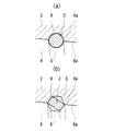
なお、ねじれ溝5,9は、図8(a)に示す半円溝や、図8(b)に示す台形溝にしても発明の目的が達成されるが、図7に詳細に示した三角形の溝が加工しやすい。その三角形の溝は、両ねじれ溝5,9間に平行四辺形の空間Sを作り出す。そのために、空間Sと相似形にする締結補助具3の断面形状は略平行四辺形になり、ねじれ溝5,9の溝面に対する締結補助具3の接触面積が広く確保される。従って、締結の緩み防止の面でも有利と言える。
The object of the invention can be achieved by using the semicircular grooves shown in FIG. 8A or the trapezoidal grooves shown in FIG. The groove is easy to process. The triangular groove creates a parallelogram space S between the
切削ヘッド1は、加工性能、耐久性、経済性を考慮して総合的に判断したときの好ましい形態として、切れ刃を、超硬合金、cBN、単結晶ダイヤモンド、多結晶ダイヤモンドなどの硬質材で形成し、切れ刃以外の箇所は、鋼や超硬合金を材料としたものが考えられる。
The cutting
シャンク2は、鋼や超硬合金を材料としたものが経済性や製造時の加工性に優れて好ましい。
The
締結補助具3は、切れ刃材質よりも軟質材、好ましくはばね鋼で形成するとよい。装着時にねじれ溝9に装着するものは縮径され、ねじれ溝5に装着するものは拡径されるようにしてねじれ溝に対する抱きつき力を増強することもできる。
The
ねじれ溝5,9のねじれ角θ、θ1は、75°以上、90°未満の範囲が適当である。そのねじれ角θ、θ1が90°に近づくほど強い軸方向締め付け力を発生させ、締結の緩みも生じ難くすることができる。また、上記の角度範囲とすることで、切削ヘッド1の着脱時間が長くなりすぎることも回避することができる。
The twist angles θ and θ1 of the
また、テーパ軸部4とテーパ孔8のテーパ嵌合部の相互接触面積(テーパ軸部の外周面とテーパ孔の内面の接触面積)は、テーパ軸部4の径方向拘束を強固にするために、ねじれ溝5,9と締結補助具3のサイズが犠牲にならない範囲でその相互接触面積はできるだけ広くするのがよい。
Further, the mutual contact area between the
その相互接触面積は、ねじれ溝5,9が無い状態でテーパ軸部4の外周面とテーパ孔8の内面を接触させたときの相互接触面積を100として、それとの比で75%以上確保することが推奨される。
As for the mutual contact area, the mutual contact area when the outer peripheral surface of the
テーパ軸部4とテーパ孔8のテーパ角α、α1は、5°〜10°程度が適当と考えられるが、これに限定されるものではなく、テーパ軸部4のねじ込み操作に要する力やねじ込み量とテーパ嵌合部に生じる径方向拘束力の兼ね合いなどを考慮して任意の値に設定することができる。
The taper angles α and α1 of the
このほか、切削ヘッドのショルダー面6とシャンクの前端面7は軸直角な面が加工性に優れるが、両者がテーパ嵌合する面であっても差し支えない。
In addition, the
工具径:φ25mm、全長:250mm、切削ヘッド1の先端からショルダー面6までの長さ:72mm、テーパ軸部4の根元直径:φ13mm、テーパ軸部4の長さ:21mm、テーパ軸部4のテーパ角α:7°、ねじれ溝5のねじれ角θ:85.8°〜84.8°、ねじれ溝5の設置ピッチP:3mm、締結補助具3の自由時大径端寸法:外径φ14.63mm、内径φ11.5mm、刃数6枚、切れ刃材質:超硬合金、切削ヘッドの本体部の材質:ダイス鋼(SKD材)の図1に示す構造のエンドミルを試作した。
その試作エンドミルは、鋼製シャンクを用いたもの(発明品1)と、超硬合金製シャンクを用いたもの(発明品2)の2種類とした。
Tool diameter: φ25 mm, full length: 250 mm, length from the tip of the cutting
The prototype end mills were of two types, one using a steel shank (Invention 1) and one using a cemented carbide shank (Invention 2).
次に、上記発明品1,2と、比較用のエンドミルを用い、BT40の仕様のマシニングセンターで以下の条件で加工を行い、そのときの切削振動と加工精度(加工面粗さと壁面直角度)を比較した。比較用のエンドミルは、工具径:φ26mmの4枚刃の高速度鋼(ハイス)製エンドミル(比較品1)と、4枚刃の刃先交換式エンドミル(比較品2)の2種類とした。
Next, using the above-described
・切削条件
被削材:S50C
加工形態:ダウンカット ドライ切削
切削速度Vc:50m/min
1刃送り量fz:0.03mm/刃,0.05mm/刃
軸方向切り込み量ap:10mm,38mm
径方向切り込み量ae:0.1mm及び0.5mm
主軸アーバのゲージラインからの工具突き出し量OH:発明品1,2=130mm、比較品1=60mm、比較品2=35mm
・ Cutting conditions Work material: S50C
Processing form: Down cut Dry cutting Cutting speed Vc: 50 m / min
1-blade feed amount fz: 0.03 mm / blade, 0.05 mm / blade Axial cut amount ap: 10 mm, 38 mm
Radial cut depth ae: 0.1 mm and 0.5 mm
Tool protrusion OH from the gauge line of the spindle arbor:
上記性能評価試験での切削振動の測定結果を図9〜図11に示す。図9は、Vc:50m/min、fz:0.03mm/刃、ap:10mm、ae:0.1mmでの切削振動、図10は、発明品2のfz:0.05mm/刃(他の条件は図9での条件と同じ)での切削振動、図11は、発明品1,2のVc:50m/min、fz:0.03mm/刃、ap:38mm、ae:0.1mm及び0.5mmでの切削振動である。
The measurement results of the cutting vibration in the performance evaluation test are shown in FIGS. FIG. 9 shows Vc: 50 m / min, fz: 0.03 mm / blade, ap: 10 mm, ae: cutting vibration at 0.1 mm, and FIG. The conditions are the same as those in FIG. 9), and FIG. 11 is Vc: 50 m / min, fz: 0.03 mm / blade, ap: 38 mm, ae: 0.1 mm and 0 for
さらに、発明品1,2による加工面粗さの測定結果を図12に、Vc:50m/min、fz:0.03mm/刃、ap:10mm、ae:0.1mmの加工条件での発明品と比較品の壁面直角度の測定結果を図13にそれぞれ示す。
Furthermore, the measurement results of the machined surface roughness of
この試験の結果、発明品の切削ヘッドが切削中に外れることはなかった。また、発明品1で加工面にややビビリマークが生じたが、図9からわかるように、発明品1,2の切削振動は、刃数が比較品よりも多く、工具突き出し量も比較品より大きいにも拘らず、比較品1,2と大差がなく、同等レベルと言えるデータが得られた。
As a result of this test, the inventive cutting head did not come off during cutting. In addition, although the chatter mark was slightly generated on the processed surface in the
また、図13からわかるように、壁面直角度は、比較品1については直角度の誤差が最大で15μmを超え、さらに、比較品2については誤差が最大で40μmにも達しているのに対し、発明品1,2はどちらも誤差が10μm未満(発明品2はその誤差が0に近い)であり、明らかに従来品に勝る加工精度が得られている。この結果から、発明品は切削ヘッドとシャンクが強固に安定して締結されていることがわかる。
In addition, as can be seen from FIG. 13, the squareness of the wall surface has a maximum error of 15 μm for the
なお、この発明は、ドリルなどの穴あけ工具、リーマ、フライス工具などにも適用することができ、適用対象はエンドミルに限定されない。 In addition, this invention can be applied also to drilling tools, such as a drill, a reamer, a milling tool, etc., and an application object is not limited to an end mill.
1 切削ヘッド
2 シャンク
3 締結補助具
4 テーパ軸部
4a 外周面
5 ねじれ溝
6 ショルダー面
7 前端面
8 テーパ孔
8a 内面
9 ねじれ溝
θ、θ1 ねじれ角
α、α1 テーパ角
P,P1 ねじれ溝の設置ピッチ
W,W1 溝幅
S ねじれ溝間に形成される空間
g 隙間
DESCRIPTION OF
Claims (6)
前記切削ヘッド(1)が、テーパ軸部(4)と、そのテーパ軸部の外周に形成されたねじれ溝(5)と、前記テーパ軸部(4)の根元から径方向外側に張り出す平坦なショルダー面(6)を後部に有し、
前記シャンク(2)が前記ショルダー面(6)を突き当てる前端面(7)と、前記テーパ軸部(4)を適合して受け入れる前記前端面(7)に開口したテーパ孔(8)と、前記テーパ軸部(4)の外周のねじれ溝(5)に対応させて前記テーパ孔(8)の内面に形成されたねじれ溝(9)を有し、
前記締結補助具(3)が、前記テーパ軸部の外周のねじれ溝(5)と前記テーパ孔の内面のねじれ溝(9)との間に形成される空間(S)と略相似形の断面形状を有し、
前記締結補助具(3)が前記テーパ軸部の外周のねじれ溝(5)と前記テーパ孔の内面のねじれ溝(9)のいずれか一方に装着され、この状態で前記テーパ軸部(4)が前記テーパ孔(8)に挿入され、前記締結補助具(3)が前記テーパ軸部の外周のねじれ溝(5)と前記テーパ孔の内面のねじれ溝(9)の双方に入り込んで双方のねじれ溝の溝面に弾性的に押しつけられ、
前記ショルダー面(6)が前記シャンクの前端面(7)に密着し、さらに、前記テーパ軸部の外周面(4a)が前記テーパ孔の内面(8a)に密着して前記切削ヘッド(1)が前記シャンク(2)に締結される着脱式切削工具。 The cutting head (1), the shank (2), and a helical coil-shaped fastening aid (3) having elasticity,
The cutting head (1) has a taper shaft portion (4), a twist groove (5) formed on the outer periphery of the taper shaft portion, and a flat surface projecting radially outward from the base of the taper shaft portion (4). A shoulder surface (6) at the rear,
A front end surface (7) against which the shank (2) abuts the shoulder surface (6), and a tapered hole (8) opened in the front end surface (7) for fittingly receiving the tapered shaft portion (4); A twist groove (9) formed on the inner surface of the taper hole (8) corresponding to the twist groove (5) on the outer periphery of the taper shaft (4);
The fastening aid (3) has a cross section substantially similar to a space (S) formed between a torsion groove (5) on the outer periphery of the tapered shaft portion and a torsion groove (9) on the inner surface of the taper hole. Has a shape,
The fastening aid (3) is mounted in one of the twisted groove (5) on the outer periphery of the tapered shaft portion and the twisted groove (9) on the inner surface of the tapered hole, and in this state, the tapered shaft portion (4) Is inserted into the taper hole (8), and the fastening aid (3) enters both the twist groove (5) on the outer periphery of the taper shaft and the twist groove (9) on the inner surface of the taper hole. Elastically pressed against the groove surface of the torsion groove,
The shoulder surface (6) is in close contact with the front end surface (7) of the shank, and the outer peripheral surface (4a) of the tapered shaft portion is in close contact with the inner surface (8a) of the tapered hole. Is a detachable cutting tool fastened to the shank (2).
Priority Applications (1)
| Application Number | Priority Date | Filing Date | Title |
|---|---|---|---|
| JP2012192878A JP5455089B2 (en) | 2012-09-03 | 2012-09-03 | Head detachable cutting tool |
Applications Claiming Priority (1)
| Application Number | Priority Date | Filing Date | Title |
|---|---|---|---|
| JP2012192878A JP5455089B2 (en) | 2012-09-03 | 2012-09-03 | Head detachable cutting tool |
Related Parent Applications (1)
| Application Number | Title | Priority Date | Filing Date |
|---|---|---|---|
| JP2010028720A Division JP5168597B2 (en) | 2010-02-12 | 2010-02-12 | Head detachable cutting tool |
Publications (2)
| Publication Number | Publication Date |
|---|---|
| JP2013010177A true JP2013010177A (en) | 2013-01-17 |
| JP5455089B2 JP5455089B2 (en) | 2014-03-26 |
Family
ID=47684531
Family Applications (1)
| Application Number | Title | Priority Date | Filing Date |
|---|---|---|---|
| JP2012192878A Active JP5455089B2 (en) | 2012-09-03 | 2012-09-03 | Head detachable cutting tool |
Country Status (1)
| Country | Link |
|---|---|
| JP (1) | JP5455089B2 (en) |
Cited By (7)
| Publication number | Priority date | Publication date | Assignee | Title |
|---|---|---|---|---|
| CN103447621A (en) * | 2013-09-09 | 2013-12-18 | 昆山奥德鲁自动化技术有限公司 | Shock absorption reamer |
| CN103639506A (en) * | 2013-12-23 | 2014-03-19 | 哈尔滨理工大学 | Special cutter bar for wide-line processing of mold |
| JP2017019097A (en) * | 2015-07-13 | 2017-01-26 | 張 新添 | Cutting tool |
| WO2019123652A1 (en) * | 2017-12-22 | 2019-06-27 | 株式会社牧野フライス製作所 | T-shaped tool and method for manufacturing t-shaped tool |
| WO2020218556A1 (en) * | 2019-04-26 | 2020-10-29 | 株式会社牧野フライス製作所 | T-shaped tool, and method for manufacturing t-shaped tool |
| JP7201856B1 (en) | 2022-03-07 | 2023-01-10 | 株式会社スギノマシン | rotary tool |
| JP7545789B2 (en) | 2020-05-27 | 2024-09-05 | 株式会社Subaru | Hole finishing tool and method for manufacturing hole finishing product |
Citations (4)
| Publication number | Priority date | Publication date | Assignee | Title |
|---|---|---|---|---|
| JPH1194023A (en) * | 1997-09-18 | 1999-04-09 | Nec Eng Ltd | Buffer support structure with locking mechanism |
| JP2005034939A (en) * | 2003-07-14 | 2005-02-10 | Hitachi Tool Engineering Ltd | Cutting edge member, tool holder and cutting tool |
| JP2007223041A (en) * | 1994-08-29 | 2007-09-06 | Sandvik Intellectual Property Ab | End mill with detachable top |
| JP2007290120A (en) * | 2006-04-20 | 2007-11-08 | Sandvik Intellectual Property Ab | Tool for removing chip, parts thereof, and screw joint |
-
2012
- 2012-09-03 JP JP2012192878A patent/JP5455089B2/en active Active
Patent Citations (4)
| Publication number | Priority date | Publication date | Assignee | Title |
|---|---|---|---|---|
| JP2007223041A (en) * | 1994-08-29 | 2007-09-06 | Sandvik Intellectual Property Ab | End mill with detachable top |
| JPH1194023A (en) * | 1997-09-18 | 1999-04-09 | Nec Eng Ltd | Buffer support structure with locking mechanism |
| JP2005034939A (en) * | 2003-07-14 | 2005-02-10 | Hitachi Tool Engineering Ltd | Cutting edge member, tool holder and cutting tool |
| JP2007290120A (en) * | 2006-04-20 | 2007-11-08 | Sandvik Intellectual Property Ab | Tool for removing chip, parts thereof, and screw joint |
Cited By (14)
| Publication number | Priority date | Publication date | Assignee | Title |
|---|---|---|---|---|
| CN103447621A (en) * | 2013-09-09 | 2013-12-18 | 昆山奥德鲁自动化技术有限公司 | Shock absorption reamer |
| CN103639506A (en) * | 2013-12-23 | 2014-03-19 | 哈尔滨理工大学 | Special cutter bar for wide-line processing of mold |
| CN103639506B (en) * | 2013-12-23 | 2017-02-15 | 哈尔滨理工大学 | Special cutter bar for wide-line processing of mold |
| JP2017019097A (en) * | 2015-07-13 | 2017-01-26 | 張 新添 | Cutting tool |
| JPWO2019123652A1 (en) * | 2017-12-22 | 2020-10-22 | 株式会社牧野フライス製作所 | How to make T-shaped tools and T-shaped tools |
| CN111511492A (en) * | 2017-12-22 | 2020-08-07 | 株式会社牧野铣床制作所 | T-shaped cutter and manufacturing method thereof |
| WO2019123652A1 (en) * | 2017-12-22 | 2019-06-27 | 株式会社牧野フライス製作所 | T-shaped tool and method for manufacturing t-shaped tool |
| CN111511492B (en) * | 2017-12-22 | 2023-08-22 | 株式会社牧野铣床制作所 | T-shaped cutter and T-shaped cutter manufacturing method |
| WO2020218556A1 (en) * | 2019-04-26 | 2020-10-29 | 株式会社牧野フライス製作所 | T-shaped tool, and method for manufacturing t-shaped tool |
| JP2020182980A (en) * | 2019-04-26 | 2020-11-12 | 株式会社牧野フライス製作所 | T-shaped tool and method of manufacturing the same |
| US11872643B2 (en) | 2019-04-26 | 2024-01-16 | Makino Milling Machine Co., Ltd. | T-shaped tool, and method for manufacturing T-shaped tool |
| JP7545789B2 (en) | 2020-05-27 | 2024-09-05 | 株式会社Subaru | Hole finishing tool and method for manufacturing hole finishing product |
| JP7201856B1 (en) | 2022-03-07 | 2023-01-10 | 株式会社スギノマシン | rotary tool |
| JP2023129829A (en) * | 2022-03-07 | 2023-09-20 | 株式会社スギノマシン | rotary tool |
Also Published As
| Publication number | Publication date |
|---|---|
| JP5455089B2 (en) | 2014-03-26 |
Similar Documents
| Publication | Publication Date | Title |
|---|---|---|
| JP5455089B2 (en) | Head detachable cutting tool | |
| JP2011161583A (en) | Head attaching and detaching type cutting tool | |
| JP4993528B2 (en) | Cutting tools | |
| US20060045639A1 (en) | Multiple-axis cutting toroidal end mill | |
| JP5713144B2 (en) | Tip changeable cutting tool | |
| US20170182564A1 (en) | Drill head for deep hole cutting | |
| US10124421B2 (en) | End milling cutter for heat-resistant superalloys | |
| US6241433B1 (en) | Tool and cutting head for cutting machining | |
| US20140056658A1 (en) | Cutting tool with removable head | |
| US7320566B2 (en) | Cutting tool including detachable cutter head | |
| JP5488374B2 (en) | Replaceable head cutting tool | |
| US20180297128A1 (en) | End mill | |
| WO2013057776A1 (en) | Head replacement-type cutting tool | |
| US8292553B2 (en) | Deburring tool and cutting insert | |
| JP3822506B2 (en) | Tool holder, cutting edge member and cutting tool | |
| US10814408B2 (en) | Replaceable-tip cutting tool main body and replaceable-tip cutting tool | |
| US20150061236A1 (en) | Soldered machining tool and soldered bar stock for forming the soldered machining tool | |
| JPH1080816A (en) | Solid ball end mill | |
| JP2005034939A (en) | Cutting edge member, tool holder and cutting tool | |
| KR101064753B1 (en) | A connection device for holder of cutting tool | |
| JP2007245295A (en) | Insert detachable-type drill | |
| CN217913256U (en) | Milling process uses dual-purpose thread milling cutter based on aeroengine | |
| JP2010099794A (en) | Screw machining tool with interchangeable screw machining portion | |
| CN218503423U (en) | Drill chuck | |
| CN210755577U (en) | Reamer with auxiliary support |
Legal Events
| Date | Code | Title | Description |
|---|---|---|---|
| A131 | Notification of reasons for refusal |
Free format text: JAPANESE INTERMEDIATE CODE: A131 Effective date: 20130827 |
|
| A521 | Request for written amendment filed |
Free format text: JAPANESE INTERMEDIATE CODE: A523 Effective date: 20131023 |
|
| TRDD | Decision of grant or rejection written | ||
| A01 | Written decision to grant a patent or to grant a registration (utility model) |
Free format text: JAPANESE INTERMEDIATE CODE: A01 Effective date: 20131210 |
|
| A61 | First payment of annual fees (during grant procedure) |
Free format text: JAPANESE INTERMEDIATE CODE: A61 Effective date: 20131226 |
|
| R150 | Certificate of patent or registration of utility model |
Ref document number: 5455089 Country of ref document: JP Free format text: JAPANESE INTERMEDIATE CODE: R150 Free format text: JAPANESE INTERMEDIATE CODE: R150 |
|
| R250 | Receipt of annual fees |
Free format text: JAPANESE INTERMEDIATE CODE: R250 |
|
| R250 | Receipt of annual fees |
Free format text: JAPANESE INTERMEDIATE CODE: R250 |
|
| R250 | Receipt of annual fees |
Free format text: JAPANESE INTERMEDIATE CODE: R250 |
|
| R250 | Receipt of annual fees |
Free format text: JAPANESE INTERMEDIATE CODE: R250 |
|
| R250 | Receipt of annual fees |
Free format text: JAPANESE INTERMEDIATE CODE: R250 |
|
| R250 | Receipt of annual fees |
Free format text: JAPANESE INTERMEDIATE CODE: R250 |
|
| R250 | Receipt of annual fees |
Free format text: JAPANESE INTERMEDIATE CODE: R250 |
|
| R250 | Receipt of annual fees |
Free format text: JAPANESE INTERMEDIATE CODE: R250 |