JP2013003841A - Information processing device, information processing method, and program - Google Patents
Information processing device, information processing method, and program Download PDFInfo
- Publication number
- JP2013003841A JP2013003841A JP2011134263A JP2011134263A JP2013003841A JP 2013003841 A JP2013003841 A JP 2013003841A JP 2011134263 A JP2011134263 A JP 2011134263A JP 2011134263 A JP2011134263 A JP 2011134263A JP 2013003841 A JP2013003841 A JP 2013003841A
- Authority
- JP
- Japan
- Prior art keywords
- proximity detection
- information processing
- detection
- proximity
- processing apparatus
- Prior art date
- Legal status (The legal status is an assumption and is not a legal conclusion. Google has not performed a legal analysis and makes no representation as to the accuracy of the status listed.)
- Abandoned
Links
Images


Classifications
-
- G—PHYSICS
- G06—COMPUTING; CALCULATING OR COUNTING
- G06F—ELECTRIC DIGITAL DATA PROCESSING
- G06F3/00—Input arrangements for transferring data to be processed into a form capable of being handled by the computer; Output arrangements for transferring data from processing unit to output unit, e.g. interface arrangements
- G06F3/01—Input arrangements or combined input and output arrangements for interaction between user and computer
- G06F3/03—Arrangements for converting the position or the displacement of a member into a coded form
- G06F3/041—Digitisers, e.g. for touch screens or touch pads, characterised by the transducing means
- G06F3/0416—Control or interface arrangements specially adapted for digitisers
- G06F3/0418—Control or interface arrangements specially adapted for digitisers for error correction or compensation, e.g. based on parallax, calibration or alignment
- G06F3/04186—Touch location disambiguation
-
- G—PHYSICS
- G06—COMPUTING; CALCULATING OR COUNTING
- G06F—ELECTRIC DIGITAL DATA PROCESSING
- G06F3/00—Input arrangements for transferring data to be processed into a form capable of being handled by the computer; Output arrangements for transferring data from processing unit to output unit, e.g. interface arrangements
- G06F3/01—Input arrangements or combined input and output arrangements for interaction between user and computer
- G06F3/048—Interaction techniques based on graphical user interfaces [GUI]
- G06F3/0487—Interaction techniques based on graphical user interfaces [GUI] using specific features provided by the input device, e.g. functions controlled by the rotation of a mouse with dual sensing arrangements, or of the nature of the input device, e.g. tap gestures based on pressure sensed by a digitiser
- G06F3/0488—Interaction techniques based on graphical user interfaces [GUI] using specific features provided by the input device, e.g. functions controlled by the rotation of a mouse with dual sensing arrangements, or of the nature of the input device, e.g. tap gestures based on pressure sensed by a digitiser using a touch-screen or digitiser, e.g. input of commands through traced gestures
- G06F3/04886—Interaction techniques based on graphical user interfaces [GUI] using specific features provided by the input device, e.g. functions controlled by the rotation of a mouse with dual sensing arrangements, or of the nature of the input device, e.g. tap gestures based on pressure sensed by a digitiser using a touch-screen or digitiser, e.g. input of commands through traced gestures by partitioning the display area of the touch-screen or the surface of the digitising tablet into independently controllable areas, e.g. virtual keyboards or menus
-
- G—PHYSICS
- G06—COMPUTING; CALCULATING OR COUNTING
- G06F—ELECTRIC DIGITAL DATA PROCESSING
- G06F2203/00—Indexing scheme relating to G06F3/00 - G06F3/048
- G06F2203/041—Indexing scheme relating to G06F3/041 - G06F3/045
- G06F2203/04101—2.5D-digitiser, i.e. digitiser detecting the X/Y position of the input means, finger or stylus, also when it does not touch, but is proximate to the digitiser's interaction surface and also measures the distance of the input means within a short range in the Z direction, possibly with a separate measurement setup
-
- G—PHYSICS
- G06—COMPUTING; CALCULATING OR COUNTING
- G06F—ELECTRIC DIGITAL DATA PROCESSING
- G06F3/00—Input arrangements for transferring data to be processed into a form capable of being handled by the computer; Output arrangements for transferring data from processing unit to output unit, e.g. interface arrangements
- G06F3/01—Input arrangements or combined input and output arrangements for interaction between user and computer
- G06F3/03—Arrangements for converting the position or the displacement of a member into a coded form
- G06F3/041—Digitisers, e.g. for touch screens or touch pads, characterised by the transducing means
- G06F3/044—Digitisers, e.g. for touch screens or touch pads, characterised by the transducing means by capacitive means
- G06F3/0446—Digitisers, e.g. for touch screens or touch pads, characterised by the transducing means by capacitive means using a grid-like structure of electrodes in at least two directions, e.g. using row and column electrodes
Abstract
Description
この技術は、情報処理装置と情報処理方法ならびにプログラムに関する。詳しくは、入力操作を正しく行うことができる情報処理装置と情報処理方法ならびにプログラムを提供する。 This technology relates to an information processing apparatus, an information processing method, and a program. Specifically, an information processing apparatus, an information processing method, and a program capable of correctly performing an input operation are provided.
近年、携帯電話装置や携帯情報端末、携帯音楽プレーヤなどの各種電子機器では、静電容量方式や抵抗膜方式等のタッチパネルを設けて入力操作を行うことが可能とされている。静電容量方式のタッチパネルでは、特許文献1,特許文献2のように、指や接触ペン等の操作体をタッチパネル操作面に接触させることにより生じた静電容量の変化を検出することで、その接触位置が検出されている。
In recent years, various electronic devices such as a mobile phone device, a portable information terminal, and a portable music player can be provided with a touch panel such as a capacitance method or a resistance film method to perform an input operation. In a capacitive touch panel, as in
ところで、静電容量方式のタッチパネルでは、入力操作だけでなく他の操作で静電容量が変化した場合でも、入力操作が行われたと誤検出されてしまう場合がある。図1は、タッチパネルを用いた情報処理装置の断面概略図を例示している。情報処理装置の筐体50の内部には表示部21が設けられており、表示部21の表示面側にセンサ部11であるタッチパネルが設けられている。ここで、例えばユーザが図1の(A)に示すように筐体50を持った場合、静電容量の変化が生じて、指FGに近接したアクティブ領域ARbで入力操作が行われたと誤検出されてしまう場合がある。また、図1の(B)に示すように指FGが非アクティブ領域ARaに近接した場合、または図1の(C)に示すように指が非アクティブ領域ARaに接触した場合にも、同様に入力操作が行われたと誤検出されてしまう場合がある。
By the way, in the capacitive touch panel, there is a case where it is erroneously detected that the input operation is performed even when the capacitance is changed not only by the input operation but also by another operation. FIG. 1 illustrates a schematic cross-sectional view of an information processing apparatus using a touch panel. A
そこで、この技術では入力操作を正しく行うことができる情報処理装置と情報処理方法ならびにプログラムを提供することを目的とする。 Accordingly, an object of the present technology is to provide an information processing apparatus, an information processing method, and a program that can correctly perform an input operation.
この技術の第1の側面は、操作体の近接および接触に応じたセンサ信号を生成するセンサ部と、前記センサ信号に基づき、前記操作体の近接検出を行う近接検出部と、前記近接検出によって検出された検出位置が、前記操作体の接触の検出が可能な領域内に設けた操作可能領域内であるか否かに応じて、前記近接検出結果の有効性を判別する判別部とを備える情報処理装置にある。 A first aspect of the technology includes a sensor unit that generates a sensor signal according to the proximity and contact of the operating body, a proximity detection unit that performs proximity detection of the operating body based on the sensor signal, and the proximity detection A determination unit configured to determine the validity of the proximity detection result according to whether or not the detected detection position is within an operable region provided in an area where the contact of the operating body can be detected; It is in the information processing device.
この技術においては、センサ部例えば静電容量方式のタッチパネルによって、操作体の近接および接触に応じて生成されたセンサ信号に基づき、操作体の近接検出が近接検出部で行われる。判別部では、近接検出によって検出された検出位置が、例えば操作体の接触の検出が可能な領域内に設けた操作可能領域内である場合に近接検出結果が有効とされて、操作可能領域外である場合に検出無効フラグを設定して近接検出結果が無効とされる。また、検出位置が操作可能領域外の位置であるため検出無効フラグが設定されており、検出位置が移動して操作可能領域内の検出無効フラグ解除領域の位置となった場合には、検出無効フラグが解除されて近接検出結果が有効とされる。また、近接検出部で操作体が検出されている場合、表示部で操作可能領域が識別可能に表示される。 In this technique, proximity detection of the operating body is performed by the proximity detection unit based on a sensor signal generated according to the proximity and contact of the operating body by a sensor unit, for example, a capacitive touch panel. In the determination unit, the proximity detection result is validated when the detection position detected by proximity detection is within an operable area provided in an area where contact of the operating body can be detected, for example, and the outside of the operable area If it is, the detection invalid flag is set and the proximity detection result is invalidated. In addition, the detection invalid flag is set because the detection position is outside the operable area, and if the detection position moves to the position of the detection invalid flag release area within the operable area, the detection invalidity The flag is released and the proximity detection result is validated. Further, when the operating body is detected by the proximity detection unit, the operable region is displayed on the display unit in an identifiable manner.
また、近接検出によって複数の操作体が検出された場合、検出された操作体に対して優先順位が設定される。例えば、操作体の接触の検出が可能な領域内に設けた所定領域に位置する操作体の優先順位が高くされる。また、所定領域に複数の操作体が位置する場合、センサ信号の信号強度が高い操作体の優先順位が高くされる。このようにして設定された優先順位に基づいて近接検出結果が採用される。さらに、判別部では、近接検出によって検出された操作体の検出サイズが閾値よりも大きい場合に、この操作体が無効と判別される。また、検出された複数の操作体の近接検出結果に基づき、個々の操作体に対応する領域表示を表示部で行い、センサ信号の信号強度に応じて領域表示の表示サイズを設定する処理や、検出された複数の操作体の近接検出結果に基づき、複数の近接検出結果が示す位置で囲まれる領域を表示部で表示する処理が行われる。 Further, when a plurality of operating objects are detected by proximity detection, a priority order is set for the detected operating objects. For example, the priority of the operating body positioned in a predetermined area provided in the area where the contact of the operating body can be detected is increased. Further, when a plurality of operating bodies are located in the predetermined area, the priority order of the operating body having a high signal strength of the sensor signal is increased. The proximity detection result is adopted based on the priority order set in this way. Further, the determination unit determines that the operation tool is invalid when the detection size of the operation tool detected by the proximity detection is larger than the threshold value. In addition, based on the detected proximity detection results of the plurality of operating bodies, the display unit displays the area corresponding to each operating body, and the process of setting the display size of the area display according to the signal intensity of the sensor signal, Based on the detected proximity detection results of the plurality of operating bodies, a process of displaying an area surrounded by the positions indicated by the plurality of proximity detection results on the display unit is performed.
さらに、近接検出部における近接検出の検出感度が近接検出制御部によって制御されて、例えば操作体の接触の検出が可能な領域の端部側の検出感度が他の部分よりも低下される。 Furthermore, the detection sensitivity of the proximity detection in the proximity detection unit is controlled by the proximity detection control unit, and for example, the detection sensitivity on the end side of the region where the contact of the operating body can be detected is lower than the other parts.
この技術の第2の側面は、操作体の近接および接触に応じたセンサ信号を生成する工程と、前記センサ信号に基づき、前記操作体の近接検出を行う工程と、前記近接検出によって検出された検出位置が、前記操作体の接触の検出が可能な領域内に設けた操作可能領域内であるか否かに応じて、前記近接検出結果の有効性を判別する工程とを含む情報処理方法にある。 The second aspect of the technology is detected by the step of generating a sensor signal corresponding to the proximity and contact of the operating body, the step of performing proximity detection of the operating body based on the sensor signal, and the proximity detection. And determining the effectiveness of the proximity detection result according to whether or not the detection position is within an operable area provided in an area where the contact of the operating body can be detected. is there.
この技術の第3の側面は、センサ部で操作体の近接および接触に応じて生成されたセンサ信号に基づき、前記操作体の近接検出を行う手順と、前記近接検出によって検出された検出位置が、前記操作体の接触の検出が可能な領域内に設けた操作可能領域内であるか否かに応じて、前記近接検出結果の有効性を判別する手順とをコンピュータで実行させるプログラムにある。 According to a third aspect of the present technology, a procedure for performing proximity detection of the operating body based on a sensor signal generated according to the proximity and contact of the operating body in the sensor unit, and a detection position detected by the proximity detection are as follows. A program for causing a computer to execute a procedure for determining the validity of the proximity detection result according to whether or not the operation object is in an operable region provided in an area where contact of the operating body can be detected.
なお、本技術のプログラムは、例えば、様々なプログラム・コードを実行可能な汎用コンピュータに対して、コンピュータ可読な形式で提供する記憶媒体、通信媒体、例えば、光ディスクや磁気ディスク、半導体メモリなどの記憶媒体、あるいは、ネットワークなどの通信媒体によって提供可能なプログラムである。このようなプログラムをコンピュータ可読な形式で提供することにより、コンピュータ上でプログラムに応じた処理が実現される。 Note that the program of the present technology is, for example, a storage medium or a communication medium provided in a computer-readable format to a general-purpose computer that can execute various program codes, such as an optical disk, a magnetic disk, or a semiconductor memory. It is a program that can be provided by a medium or a communication medium such as a network. By providing such a program in a computer-readable format, processing corresponding to the program is realized on the computer.
この技術によれば、操作体の近接および接触に応じて生成されたセンサ信号に基づき、操作体の近接検出が行われて、近接検出によって検出された検出位置が、操作体の接触の検出が可能な領域内に設けた操作可能領域内であるか否かに応じて、近接検出結果の有効性が判別される。このため、誤検出を防止して入力操作を正しく行うことができるようになる。 According to this technique, the proximity detection of the operating body is performed based on the sensor signal generated according to the proximity and contact of the operating body, and the detection position detected by the proximity detection detects the contact of the operating body. The effectiveness of the proximity detection result is determined depending on whether or not the operation area is within the operable area. For this reason, it becomes possible to prevent erroneous detection and perform an input operation correctly.
以下、本技術を実施するための形態について説明する。なお、説明は以下の順序で行う。
1.情報処理装置の構成
2.情報処理装置の動作
2−1.第1の動作
2−2.第2の動作
2−3.第3の動作
Hereinafter, embodiments for carrying out the present technology will be described. The description will be given in the following order.
1. 1. Configuration of information processing apparatus 2. Operation of information processing apparatus 2-1. First operation 2-2. Second operation 2-3. Third action
<1.情報処理装置の構成>
本技術を用いた情報処理装置は、図1に示すように、情報処理装置の筐体50の内部に表示部21が設けられており、表示部21の表示面側にセンサ部11が設けられた構成とされている。
<1. Configuration of information processing apparatus>
As shown in FIG. 1, the information processing apparatus using the present technology includes a
センサ部11は、静電容量方式のタッチパネルが用いられている。図2は、タッチパネルの構成を示している。
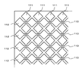
The
タッチパネルは、透光性基板が用いられており、操作入力を受け付けるアクティブ領域には、第1の方向に延在する複数列の第1透光性電極パターン111と、第1の方向に交差する第2の方向に延在する複数列の第2透光性電極パターン112が形成されている。
タッチパネルでは、複数の第1透光性電極パターン111および第2透光性電極パターン112に電圧を順に印加した場合、指やタッチペン等の操作体が近傍に位置したり、近接または接触していると、第1透光性電極パターン111および第2透光性電極パターン112と、操作体との間に静電容量が生じる。したがって、静電容量の変化から操作体が近傍に位置していることや、いずれの箇所に操作体が近接または接触しているかを検出することができる。
The touch panel uses a translucent substrate, and the active region that receives an operation input intersects the first
In the touch panel, when a voltage is sequentially applied to the plurality of first
第1透光性電極パターン111と第2透光性電極パターン112は透光性基板の同一面上に同一層により形成されている。また、第1透光性電極パターン111と第2透光性電極パターン112とは透光性基板の同一面上に同一層により形成されているため、第1透光性電極パターン111と第2透光性電極パターン112との交差部分が複数存在する。
The first
そこで、複数の交差部分のいずれにおいても、第1透光性電極パターン111および第2透光性電極パターン112のうちの一方の電極パターンは、交差部分でも繋がっている一方、他方の電極パターンは途切れている構成になっている。本形態では、複数の交差部分のいずれにおいても、第1透光性電極パターン111が繋がっている一方、第2透光性電極パターン112は途切れている構成になっている。
Therefore, in any of the plurality of intersecting portions, one electrode pattern of the first
交差部分における第1透光性電極パターン111の上層側には、透光性の層間絶縁膜が形成されている。層間絶縁膜の上層には、交差部分で途切れている第2透光性電極パターン112同士を電気的に接続する透光性の中継電極113(斜線部)が形成されている。このため、第2透光性電極パターンは第2の方向で電気的に接続されている。
A translucent interlayer insulating film is formed on the upper layer side of the first
ここで、第1透光性電極パターン111および第2透光性電極パターン112は各々、交差部分で挟まれた領域に菱形形状の大面積のパッド部を備えている。第1透光性電極パターン111において交差部分に位置する接続部分は、パッド部より幅の狭い細幅形状になっている。また、中継電極113も、パッド部より幅の狭い細幅形状で短冊状に形成されている。このように構成されたセンサ部11は、操作体の近接や接触等によって生じた静電容量の変化を示すセンサ信号を生成して近接検出部12に出力する。
Here, each of the first
表示部21は、液晶表示素子等の平面状表示素子を用いて構成されている。表示部21は、情報処理装置の設定や動作切り替えを行うためのメニュー画面等を表示する。
The
なお、情報処理装置では、表示部21と筐体50との間にバックライトを設けて、表示部21の背面側、すなわち筐体50と対向する面側から、表示部21を照らすことで、表示部21の表示を見やすくする構成であってもよい。
In the information processing apparatus, a backlight is provided between the
図2は、情報処理装置の機能ブロック図を示している。情報処理装置10は、センサ部11、近接検出部12、判別部13、近接検出制御部14、表示部21およびシステム制御部30を有している。
FIG. 2 shows a functional block diagram of the information processing apparatus. The
センサ部11は、上述のように、操作体の近接や接触によって生じた静電容量の変化を示すセンサ信号を生成して、近接検出部12に出力する。
As described above, the
近接検出部12は、センサ部11からのセンサ信号に基づき、操作体の近接検出を行う。近接検出部12は、近接検出を行い検出結果を判別部13に出力する。近接検出では、近傍検出状態であることを示す検出結果や、近接検出状態であることを示す検出結果を生成する。近傍検出状態とは、操作体の位置は検出できないがセンサ部11の近傍に操作体がある状態をいう。また近接検出状態とは、センサ部11に近接または接触している操作体の位置を検出している状態をいう。
The
判別部13は、近接検出によって検出された検出位置が、操作体の接触の検出が可能な領域内に設けた操作可能領域内であるか否かに応じて、近接検出結果の有効性を判別する。判別部13は、有効な近接検出結果または近接検出結果と有効性の判別結果をシステム制御部30に出力する。また、判別部13は、近接検出によって複数の操作体が検出された場合、検出された操作体に対して優先順位を設定して、設定した優先順位に基づいて近接検出結果を採用してシステム制御部30に出力する。
The
近接検出制御部14は、システム制御部30から供給された制御信号や判別部13の判別結果に基づき、近接検出部12における近接検出の検出感度を制御する。
The proximity
システム制御部30は、表示信号を生成して表示部21に出力する。また、システム制御部30は、判別部13から供給された近接検出結果に基づき、近接検出結果の個別処理または統合処理を行う。さらに、システム制御部30は、判別部13から供給された近接検出結果と、表示部21で行われている表示から、ユーザが行った操作を判別して、判別結果に基づき、情報処理装置10の動作がユーザ操作に応じた動作となるように制御を行う。
The
<2.情報処理装置の動作>
情報処理装置10は、近接検出によって検出された操作体の検出位置が、操作体の接触検出が可能な領域内に設けた操作可能領域内であるか否かに応じて、近接検出結果の有効性を判別することで、入力操作の誤検出を防止する。また、情報処理装置10は、近接検出において複数の操作体を検出した場合には、検出された操作体に対して優先順位を設定して、設定した優先順位に基づいて近接検出結果を採用することで、入力操作の誤検出を防止する。さらに、情報処理装置10は、操作体の近接検出における検出感度を制御して誤検出を防止する。以下、第1の動作では、近接検出結果の有効性を判別する場合の動作について説明する。第2の動作では、複数の操作体を検出した場合の動作について説明する。さらに、第3の動作では、近接検出の検出感度を制御する場合の動作について説明する。
<2. Operation of information processing apparatus>
The
<2−1.第1の動作>
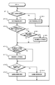
図4は、情報処理装置10の第1の動作を示すフローチャートである。ステップST1で情報処理装置10は、近傍/近接検出状態であるか判別する。情報処理装置10は、操作体がセンサ部11に近づいて近傍検出状態となった場合、また、操作体がセンサ部11に近接または接触したことにより近接検出状態となった場合にステップST2に進む。また、情報処理装置10は他の場合にステップST11に進む。
<2-1. First operation>
FIG. 4 is a flowchart showing a first operation of the
ステップST2で情報処理装置10は、操作可能領域を表示する。情報処理装置10は、操作体がタッチパネルに近づいていることから、操作可能領域を表示部21で表示してステップST3に進む。操作可能領域ARpは、図5に示すように、操作体の接触の検出が可能な領域であるアクティブ領域ARb内に設けた領域であり、表示部21の表示と関係付けられている。
In step ST2, the
ステップST3で情報処理装置10は、近傍検出状態から最初に近接検出状態に移行したか判別する。情報処理装置10は、操作体がセンサ部11の近傍状態から最初に近接または接触した状態になった場合はステップST4に進み、他の場合にはステップST6に進む。
In step ST <b> 3, the
ステップST4で情報処理装置10は、検出位置が操作可能領域内である場合はステップST6に進み、他の場合にはステップST5に進む。
In step ST4, the
ステップST5で情報処理装置10は、検出無効フラグを設定してステップST6に進む。
In step ST5, the
ステップST6で情報処理装置10は、検出無効フラグが設定されており、検出位置が検出無効フラグ解除領域内であるか判別する。検出無効フラグ解除領域ARqは、図5に示すように、操作可能領域ARp内に設けられた領域である。情報処理装置10は、検出無効フラグが設定されており、検出位置が検出無効フラグ解除領域内である場合、ステップST7に進む。また、情報処理装置10は、他の場合ステップST8に進む。
In step ST6, the
ステップST7で情報処理装置10は、検出無効フラグを解除する。情報処理装置10は、設定されている検出無効フラグを解除してステップST8に進む。
In step ST7, the
ステップST8で情報処理装置10は、検出無効フラグが設定状態であるか判別する。情報処理装置10は、検出無効フラグが設定されている場合にステップST9に進み、検出無効フラグが解除とされている場合にステップST10に進む。
In step ST8, the
ステップST9で情報処理装置10は、近接検出部12で生成された近接検出結果を無効としてステップST1に戻る。
In step ST9, the
ステップST10で情報処理装置10は、近接検出部12で生成された近接検出結果を有効としてステップST1に戻る。
In step ST10, the
ステップST1からステップST11に進むと、情報処理装置10は操作可能領域を非表示とする。操作体がセンサ部11に近接または接触しておらず、また近傍の位置でもない場合、ユーザ操作が行われていることを判別できない。したがって、情報処理装置10は、操作可能領域を非表示とする。また、情報処理装置10は、操作可能領域を表示しない場合に例えばバックライトを消灯することで、消費電力を削減できる。
When the process proceeds from step ST1 to step ST11, the
なお、ステップST1からステップST11までの処理を全て行う必要はなく、一部の処理を選択的に行うようにしてもよい。例えばステップST3からステップST10の処理のみを行うようにしてもよい。 Note that it is not necessary to perform all the processes from step ST1 to step ST11, and some processes may be selectively performed. For example, only the processing from step ST3 to step ST10 may be performed.
図6は、操作可能領域の表示を例示している。情報処理装置10は、近傍/近接検出状態でない場合、図6の(A)における「ボタン1」のように操作可能領域を非表示とする。また、「ボタン2」のように明度の低い色とする。また、表示サイズを可変させる場合、ボタン表示を小さいサイズとする。なお、操作可能領域を非表示とする場合、例えばバックライトを消灯として、表示部21の表示を黒表示としてもよい。また、待ち受け画面表示としてもよい。
FIG. 6 illustrates the display of the operable area. When not in the proximity / proximity detection state, the
また、操作体がセンサ部11に近づいて近傍検出状態または近傍検出状態となっている場合、例えば図6の(B)における「ボタン1」のように操作可能領域を表示する。また、「ボタン2」のように明度の高い色とする。また、表示サイズを可変させる場合、「ボタン3」のように大きいサイズの表示とする。なお、操作可能領域の非表示においてバックライトを消灯している場合は、バックライトを点灯して、表示部21で表示を行う。また、操作可能領域の表示では、ボタンやアイコン表示にグラデーションやアニメーションを加えることで、表示状態であることを識別可能としてもよい。
Further, when the operating body approaches the
図7は、操作体の動きと近傍検出結果の関係を示している。図7の(A)に示すように、操作体がセンサ部11に近づいて近傍検出状態となり、その後初めて近接検出状態となったときの検出位置が操作可能領域ARpの外であるときは、検出無効フラグが設定される。また、検出無効フラグが設定されている場合は、近接検出結果が無効とされる。このように、近接検出結果が無効とされるので、操作体が操作可能領域外に近づいた場合に誤検出を生じることがない。
FIG. 7 shows the relationship between the movement of the operating tool and the vicinity detection result. As shown in FIG. 7A, when the operating body approaches the
また、近傍検出状態から初めて近接検出状態に移行して検出無効フラグが設定されると、図7の(B)に示すように、操作体が操作可能領域ARp内であって検出無効フラグ解除領域ARqの外である位置で近接検出状態となっても近接検出結果が無効とされる。また、図7の(C)に示すように、操作体の検出位置が検出無効フラグ解除領域ARq内の位置となると、検出無効フラグが解除されて近接検出結果が有効とされる。 Further, when the detection invalid flag is set by shifting from the proximity detection state to the proximity detection state for the first time, as shown in FIG. 7B, the operation tool is in the operable area ARp and the detection invalid flag release area. Even if the proximity detection state is entered at a position outside ARq, the proximity detection result is invalidated. Further, as shown in FIG. 7C, when the detection position of the operating body becomes a position in the detection invalid flag release area ARq, the detection invalid flag is released and the proximity detection result is validated.
このように、検出無効フラグを設定する領域と検出無効フラグを解除する領域が異なる領域とされており、検出無効フラグ解除領域は、操作可能領域内であって、操作可能領域よりも狭い領域とされている。したがって、近接検出結果の有効性を安定して判別することができる。 Thus, the area for setting the detection invalid flag and the area for releasing the detection invalid flag are different areas, and the detection invalid flag release area is within the operable area and is narrower than the operable area. Has been. Therefore, the effectiveness of the proximity detection result can be determined stably.
操作可能領域や検出無効フラグ解除領域の設定は、レジスタを用いることで容易に行うことができる。例えば図8の(A)に示すように例えば8ビットのレジスタを設けて、レジスタの上位4ビットを、X軸方向における領域の範囲を設定するための閾値、レジスタの下位4ビットを、Y軸方向における領域の範囲を設定するための閾値とする。図8の(B)は、レジスタを例えば「0x42」として操作可能領域を設定する場合を示している。なお、センサ部11におけるX軸方向の解像度およびY軸方向の解像度は、それぞれに「1023」とする。
Setting of the operable area and the detection invalid flag releasing area can be easily performed by using a register. For example, as shown in FIG. 8A, an 8-bit register is provided, for example, the upper 4 bits of the register, the threshold for setting the range of the area in the X-axis direction, the lower 4 bits of the register, It is set as a threshold value for setting the range of the area in the direction. FIG. 8B shows a case where the operable area is set with the register set to “0x42”, for example. The resolution in the X-axis direction and the resolution in the Y-axis direction in the
レジスタの上位4ビットは「4」であることから、X軸方向において例えば端部側から「4×8」の範囲を除いた領域「32〜991」を操作可能領域とする。また、下位4ビットは「2」であることからY軸方向において例えば「2×8」の範囲を除いた領域「16〜1007」を操作可能領域とする。このように、レジスタを用いることで操作可能領域を容易に設定できる。また、検出無効フラグ解除領域も同様に、レジスタを用いて領域を容易に設定できる。 Since the upper 4 bits of the register are “4”, an area “32 to 991” excluding a range of “4 × 8” from the end side in the X-axis direction is set as an operable area. Since the lower 4 bits are “2”, the area “16 to 1007” excluding the range of “2 × 8”, for example, in the Y-axis direction is set as the operable area. In this manner, the operable area can be easily set by using the register. Similarly, the detection invalid flag release area can be easily set using a register.
このように、第1の動作によれば、操作体の近接および接触に応じて生成されたセンサ信号に基づき、操作体の近接検出が行われて、近接検出によって検出された検出位置が、操作体の接触の検出が可能な領域内に設けた操作可能領域内であるか否かに応じて、近接検出結果の有効性が判別される。このため、誤検出を防止して入力操作を正しく行うことができるようになる。 Thus, according to the first operation, the proximity of the operating body is detected based on the sensor signal generated in accordance with the proximity and contact of the operating body, and the detection position detected by the proximity detection is The validity of the proximity detection result is determined depending on whether or not the region is within the operable region provided in the region where the contact of the body can be detected. For this reason, it becomes possible to prevent erroneous detection and perform an input operation correctly.
また、検出位置が操作可能領域外の位置であるため検出無効フラグが設定されており、検出位置が移動して操作可能領域内の検出無効フラグ解除領域の位置となった場合には、検出無効フラグが解除されて近接検出結果が有効とされる。したがって、操作体が近接検出状態となった場合の近接検出結果を用いる従来の情報処理装置に比べて、より確かな近接検出結果を用いることが可能となる。 In addition, the detection invalid flag is set because the detection position is outside the operable area, and if the detection position moves to the position of the detection invalid flag release area within the operable area, the detection invalidity The flag is released and the proximity detection result is validated. Therefore, a more reliable proximity detection result can be used as compared with the conventional information processing apparatus that uses the proximity detection result when the operating body is in the proximity detection state.
また、検出無効フラグ解除領域は、操作可能領域の中心からオフセットさせて設定してもよい。例えば、情報処理装置を手で持ったときに、指が触れやすい部分から離れるように図7の検出無効フラグ解除領域を右方向にオフセットして設定する。このように検出無効フラグ解除領域を設定すれば、検出無効フラグが誤って解除される場合が少なくなり、より確実に誤検出を防止できるようになる。 Further, the detection invalid flag release area may be set offset from the center of the operable area. For example, when the information processing apparatus is held by hand, the detection invalid flag release region in FIG. If the detection invalid flag release area is set in this way, the detection invalid flag is less likely to be canceled by mistake, and erroneous detection can be prevented more reliably.
また、近接検出部で操作体が検出されている場合、表示部で操作可能領域が識別可能に表示される。このため、操作可能領域の位置をユーザが容易に確認できるので、表示を参照することで誤操作を防止することができる。 Further, when the operating body is detected by the proximity detection unit, the operable region is displayed on the display unit in an identifiable manner. For this reason, since the user can easily confirm the position of the operable region, an erroneous operation can be prevented by referring to the display.
<2−2.第2の動作>
図9は、情報処理装置10の第2の動作を示すフローチャートである。ステップST21で情報処理装置10は、検出面積が閾値未満の操作体があるか判別する。情報処理装置10は、検出面積が閾値未満の操作体がない場合にステップST22に進み、閾値未満の操作体がある場合はステップST23に進む。
<2-2. Second operation>
FIG. 9 is a flowchart showing a second operation of the
ステップST22で情報処理装置10は、検出面積が閾値以上の操作体を無効とする。情報処理装置10は、検出面積が閾値以上の操作体、例えば指で操作を行う場合に指よりも検出面積が大きい手の甲や手のひら等の操作体を無効としてステップST23に進む。
In step ST <b> 22, the
ステップST23で情報処理装置10は、複数の近接検出であるか判別する。情報処理装置10は、近接検出された操作体が複数である場合はステップST25に進み、1つである場合はステップST24に進む。
In step ST23, the
ステップST24で情報処理装置10は、検出した操作体を採用する。情報処理装置10は、検出面積が閾値未満である操作体が1つであることから検出した操作体を採用してステップST25に進む。
In step ST24, the
ステップST25で情報処理装置10は、マルチ近接検出モードが選択されているか判別する。情報処理装置10は、複数の近接検出結果を用いるマルチ近接検出モードが選択されている場合、ステップST31に進む。また、マルチ近接検出モードが選択されていない場合、ステップST26に進む。
In step ST25, the
ステップST26で情報処理装置10は、所定領域内に操作体があるか判別する。情報処理装置10は所定領域内、例えば操作体の接触の検出が可能な領域内であって、表示部21の画面中央から一定範囲の領域内に操作体がある場合、ステップST27に進む。また、情報処理装置10は、所定領域内に操作体がない場合ステップST30に進む。
In step ST <b> 26, the
ステップST27で情報処理装置10は、所定領域内に操作体が1つのみであるか判別する。情報処理装置10は、所定領域内に操作体が1つである場合ステップST28に進む。また、情報処理装置10は、所定領域内に操作体が複数ある場合ステップST29に進む。
In step ST27, the
ステップST28で情報処理装置10は、所定領域内の操作体を採用する。情報処理装置10は、所定領域内の操作体の近接検出結果を判別部13からシステム制御部30に出力してステップST21に戻る。
In step ST28, the
ステップST29で情報処理装置10は、所定領域内で最も信号強度が高い操作体を採用する。情報処理装置10は、所定領域内に複数の操作体が存在することから、最も信号強度が高い操作体の近接検出結果を判別部13からシステム制御部30に出力してステップST21に戻る。
In step ST29, the
ステップST26からステップST30に進むと、情報処理装置10は、全領域内で最も信号強度が高い操作体を採用する。情報処理装置10は、全領域内で最も信号強度が高い操作体の近接検出結果を判別部13からシステム制御部30に出力してステップST21に戻る。
When the process proceeds from step ST26 to step ST30, the
ステップST31で情報処理装置10は、個別処理モードであるか判別する。情報処理装置10は、複数の近接検出結果を別々に用いて処理を行う個別モードが選択されている場合、ステップST32に進む。また、個別モードが選択されていない場合、ステップST33に進む。
In step ST31, the
ステップST32で情報処理装置10は、近接検出結果の個別処理を行う。情報処理装置10は、全ての近接検出結果を個々に用いて処理を行いステップST21に戻る。例えば、個別処理として、操作体に対応する識別表示を表示部21で行う場合、近接検出で検出された操作体の検出位置に識別表示を設ける。また、操作体を検出したときの信号強度に応じて識別表示の表示サイズを設定する。
In step ST32, the
ステップST33で情報処理装置10は、統合処理を行う。情報処理装置10は、全ての近接検出結果を用いて処理を行いステップST21に戻る。例えば、統合処理として、操作体に対応する識別表示を表示部21で行う場合、近接検出で検出された操作体の検出位置で囲まれる領域を、識別表示の領域とする。
In step ST33, the
なお、ステップST21からステップST33までの処理を全て行う必要はなく、一部の処理を選択的に行うようにしてもよい。例えばステップST26からステップST30の処理のみを行うようにしてもよく、ステップST26からステップST33の処理のみを行うようにしてもよい。 In addition, it is not necessary to perform all the processes from step ST21 to step ST33, and some processes may be selectively performed. For example, only the processing from step ST26 to step ST30 may be performed, or only the processing from step ST26 to step ST33 may be performed.
図10は、操作体が複数検出された場合の信号強度を例示している。なお、図9では2本の指FG1,FG2を操作体としており、指FG1におけるX軸方向の信号強度は「Sx1」、指FG2におけるX軸方向の信号強度は「Sx2」とする。また、指FG1におけるY軸方向の信号強度は「Sy1」、指FG2におけるY軸方向の信号強度は「Sy2」とする。 FIG. 10 illustrates the signal intensity when a plurality of operating bodies are detected. In FIG. 9, two fingers FG1 and FG2 are used as operating bodies. The signal intensity in the X-axis direction of the finger FG1 is “Sx1”, and the signal intensity in the X-axis direction of the finger FG2 is “Sx2”. The signal strength in the Y-axis direction of the finger FG1 is “Sy1”, and the signal strength in the Y-axis direction of the finger FG2 is “Sy2”.
ここで、指FG1,FG2が検出されており、指FG1が破線で示す所定領域内であると、所定領域内の操作体が1つであることから、指FG1が操作体として採用されることになる。 Here, when the fingers FG1 and FG2 are detected and the finger FG1 is within the predetermined area indicated by the broken line, the operating body in the predetermined area is one, and therefore the finger FG1 is adopted as the operating body. become.
図11は、指FG1を操作体として用いる場合、手の握り部分FHがセンサ部に近接した場合を示している。手の握り部分FHは、指FG1に比べてサイズが大きい。したがって、指FG1をセンサ部に近づけると、握り部分FHもセンサ部に近づく。ここで、検出面積の閾値を握り部分FHの検出面積Sfhよりも小さく、指FG1の検出面積Sfg1よりも大きく設定しておくと、握り部分FHが操作体として検出されても無効とされる。したがって、指FG1のみを操作体として検出することが可能となり、握り部分FHが誤検出されてしまうことを防止できる。 FIG. 11 shows a case where the hand grip portion FH is close to the sensor unit when the finger FG1 is used as the operating body. The hand grip portion FH is larger in size than the finger FG1. Therefore, when the finger FG1 is brought close to the sensor unit, the grip portion FH also approaches the sensor unit. Here, if the threshold value of the detection area is set smaller than the detection area Sfh of the grip portion FH and larger than the detection area Sfg1 of the finger FG1, even if the grip portion FH is detected as an operating body, it is invalidated. Accordingly, it is possible to detect only the finger FG1 as the operating body, and it is possible to prevent the grip portion FH from being erroneously detected.
図12は、マルチ近接検出モードが選択されている場合を示している。図12の(A)は、マルチ近接検出モードが選択されている場合において、個別処理モードが選択されている場合を示している。なお、図12の(A)では、2本の指FG1,FG2を操作体としている。指FG1が指FG2よりもセンサ部11に近接しており、指FG1の信号強度が指FG2の信号強度よりも強い場合、指FG1に対応する識別表示PA1は、指FG2に対応する識別表示PA2よりも表示サイズを大きくする。このようにすれば、操作体の近接検出結果を表示部21の表示で容易に確認することができる。
FIG. 12 shows a case where the multi-proximity detection mode is selected. FIG. 12A shows a case where the individual processing mode is selected when the multi-proximity detection mode is selected. In FIG. 12A, two fingers FG1 and FG2 are used as operating bodies. When the finger FG1 is closer to the
図12の(B)は、マルチ近接検出モードが選択されている場合において、個別処理モードが選択されていない場合を示している。なお、図12の(B)では、3本の指FG1,FG2,FG3を操作体としている。指FG1〜FG3がセンサ部11に近接して検出された場合、近接検出によって検出された指FG1〜FG3の位置で囲まれる領域が識別表示PA3として表示する。このようにすれば、複数の操作体によって範囲を設定する場合、複数の近接検出結果に基づいて設定された範囲を表示することが可能となり、領域の設定状態を容易に確認できる。
FIG. 12B shows a case where the individual processing mode is not selected when the multi-proximity detection mode is selected. In FIG. 12B, three fingers FG1, FG2, and FG3 are used as operating bodies. When the fingers FG1 to FG3 are detected in proximity to the
このように、第2の動作では、近接検出によって複数の操作体が検出された場合、検出された操作体に対して優先順位が設定される。例えば、操作体の接触の検出が可能な領域内に設けた所定領域に位置する操作体や、所定領域に位置する操作体でセンサ信号の信号強度が高い操作体の優先順位が高く設定して、設定した優先順位に基づいて近接検出結果が採用される。このため、複数の操作体が検出されても、優先順位の高い近接検出結果を採用することで、誤検出を防止することができる。 Thus, in the second operation, when a plurality of operating bodies are detected by proximity detection, a priority order is set for the detected operating bodies. For example, the priority of the operation body located in a predetermined area provided in the area where the contact of the operation body can be detected or the operation body located in the predetermined area and the signal strength of the sensor signal is high is set high. The proximity detection result is adopted based on the set priority order. For this reason, even if a plurality of operating bodies are detected, it is possible to prevent erroneous detection by adopting a proximity detection result having a high priority.
また、近接検出によって検出された操作体の検出サイズが閾値よりも大きい場合に、該操作体が無効と判別される。このため、例えば指を操作可能領域に近づける場合に、手の握り部分がセンサ部に近づいても、この握り部分が操作体として誤検出されてしまうことを防止できる。 Further, when the detected size of the operating tool detected by the proximity detection is larger than the threshold value, it is determined that the operating tool is invalid. For this reason, for example, when the finger is brought close to the operable region, even if the grip portion of the hand approaches the sensor portion, it is possible to prevent the grip portion from being erroneously detected as the operating body.
さらに、複数の操作体が検出された場合、複数の近接検出結果を個々に用いた処理や、複数の近接検出結果をまとめて用いた処理を行うことができる。このため、例えば複数の操作体毎の識別表示や、複数の操作体で囲まれる領域を識別表示として表示させることが可能となり、多様な処理を行うことができる。なお、第2の動作では、個別処理モードが選択されているか否かに応じて、表示部21における識別表示を切り替える場合について説明したが、識別表示に限らず、近接検出結果に基づいて種々の処理動作を切り替えるようにしてもよい。
Furthermore, when a plurality of operating bodies are detected, processing using a plurality of proximity detection results individually or processing using a plurality of proximity detection results collectively can be performed. For this reason, for example, it becomes possible to display an identification display for each of the plurality of operating bodies and an area surrounded by the plurality of operating bodies as an identification display, and various processes can be performed. In the second operation, the case where the identification display on the
また、信号強度の高い操作体を採用する場合、信号強度が変動することにより採用される操作体が頻繁に切り替わることのないように、ヒステリシス特性を持たせて操作体の採用を行う。このような処理を行えば、安定した動作が可能となる。 In addition, when an operation body having a high signal strength is employed, the operation body is employed with a hysteresis characteristic so that the operation body to be employed is not frequently switched due to fluctuations in the signal intensity. If such processing is performed, stable operation is possible.
<2−3.第3の動作>
第1の動作と第2の動作では、操作体の位置や検出面積に基づいて、操作体の誤検出を防止しているが、第3の動作では、近接検出の検出感度を制御して誤検出を防止する場合について説明する。
<2-3. Third operation>
In the first operation and the second operation, erroneous detection of the operating body is prevented based on the position and detection area of the operating body. However, in the third operation, the detection sensitivity of proximity detection is controlled to make an error. A case of preventing detection will be described.
近接検出制御部14は、近接検出部12で行われる近接検出の検出感度を制御して誤検出を防止する。検出感度の制御は、レジスタを用いることで容易に行うことができる。例えば図13の(A)に示すように8ビットの感度調整用のレジスタを設けて、レジスタの上位4ビットで感度調整を行うか否かの設定を行い、下位4ビットでどの様な感度調整を行うか設定する。
The proximity
レジスタの最上位ビットは、例えば図13の(B)に示す左右の端部側のセンサX0,Xmの感度調整を行うか否かを設定するビットとする。また2番目のビットは、最上位ビットで感度調整を行うか否かが設定されるセンサX0,Xmよりも内側に位置する左右のセンサX1,Xm-1で、感度調整を行うか否かを設定するビットとする。また、3番目のビットは上下の端部側のセンサY0,Ynの感度調整を行うか否かを設定するビットとする。また4番目のビットは、3番目のビットで感度調整を行うか否かが設定されるセンサY0,Ynよりも内側に位置する上下のセンサY1,Yn-1で、感度調整を行うか否かを設定するビットとする。 For example, the most significant bit of the register is a bit for setting whether or not to adjust the sensitivity of the sensors X0 and Xm on the left and right end sides shown in FIG. The second bit indicates whether or not the sensitivity adjustment is performed by the left and right sensors X1 and Xm-1 located inside the sensors X0 and Xm in which the sensitivity adjustment is set by the most significant bit. The bit to be set. The third bit is a bit for setting whether or not to adjust the sensitivity of the sensors Y0 and Yn on the upper and lower ends. In the fourth bit, whether or not the sensitivity adjustment is performed by the upper and lower sensors Y1 and Yn-1 positioned inside the sensors Y0 and Yn in which whether or not the sensitivity adjustment is performed in the third bit is set. Is a bit to set.
レジスタの下位4ビットに含まれる5番目のビットでは、センサX0,Xmの感度調整を行う。6番目のビットでは、センサX1,Xm-1の感度調整を行う。7番目のビットでは、センサY0,Ynの感度調整を行う。最下位のビットでは、センサY1,Yn-1の感度調整を行う。なお、感度調整は、例えばセンサ信号と閾値を比較することで操作体の検出を行う場合に、センサ信号の利得や閾値のレベルを調整することで近接検出の感度調整を行うことができる。 The fifth bit included in the lower 4 bits of the register adjusts the sensitivity of the sensors X0 and Xm. The sixth bit adjusts the sensitivity of the sensors X1, Xm-1. The seventh bit adjusts the sensitivity of the sensors Y0 and Yn. In the least significant bit, the sensitivity of the sensors Y1 and Yn-1 is adjusted. Note that sensitivity adjustment can be performed for sensitivity detection for proximity detection by adjusting the gain of the sensor signal and the level of the threshold, for example, when detecting the operating body by comparing the sensor signal with the threshold.
図13の(B)は、感度調整レジスタを「0xE4」とした場合を示している。なお、感度調整レジスタの上位4ビットにおいて、ビットを「1」とした場合は感度調整を行い、ビットを「0」とした場合は感度調整を行わないものとする。また、下位4ビットにおいて、ビットを「1」とした場合は感度を「50%」に低下させて、ビットを「0」とした場合は感度を「0%」すなわち近接検出を行わないものとする。 FIG. 13B shows a case where the sensitivity adjustment register is “0xE4”. In the upper 4 bits of the sensitivity adjustment register, sensitivity adjustment is performed when the bit is “1”, and sensitivity adjustment is not performed when the bit is “0”. In the lower 4 bits, when the bit is “1”, the sensitivity is reduced to “50%”, and when the bit is “0”, the sensitivity is “0%”, that is, proximity detection is not performed. To do.
感度調整レジスタを「0xE4(=11100100)」とした場合、最上位ビットから3番目までのビットは「1」であることからセンサX0,X1,Xm-1,Xm,Y0,Ynでは感度調整を行う。また、4番目のビットは「0」であることから、センサY1,Yn-1では感度調整を行わない。また、5番目のビットと7番目のビットは「0」であることから、センサX0,Xm,Y0,Ynの感度は「0%」に設定される。また、6番目のビットは「1」であることから、センサX1,Xm-1の感度は「50%」に設定される。したがって、図13の(B)に示すように感度調整が行われる。
When the sensitivity adjustment register is set to “0xE4 (= 11100100)”, the most significant bit to the third bit are “1”. Therefore, the sensitivity adjustment is performed for the sensors X0, X1, Xm-1, Xm, Y0, and Yn. Do. Since the fourth bit is “0”, the sensitivity adjustment is not performed in the
このように、検出感度をエリア毎に可変できるようにすることで、例えばユーザが筐体を持ったときに触れやすい部分の感度を低下させれば、誤検出を軽減できるようになる。また、感度調整は、レジスタを用いて行う場合に限られない。例えば、センサ部11から各センサのセンサ信号を読み出す際に、読出位置と感度の関係を示すテーブルを用意して、テーブルに基づき感度調整を行うようにしてもよい。
In this manner, by making the detection sensitivity variable for each area, for example, if the sensitivity of a portion that is easy to touch when the user holds the housing is reduced, erroneous detection can be reduced. Further, the sensitivity adjustment is not limited to the case of using a register. For example, when reading the sensor signal of each sensor from the
また、表示部21でアイコン等の表示がない領域などは感度を「0」として、センサ信号の読み出しを行わないようにすれば低消費電力化も可能となる。さらに、既に得られている近接検出結果に応じて検出感度の指向性を持たせるようにすることもできる。例えば、操作体である指の移動方向に対して検出感度を高めるようにすれば、操作体の検出精度を高めることが可能となる。
In addition, in a region where an icon or the like is not displayed on the
また、感度調整ではセンサ部11の表面に接地層を設けてもよい。例えば、センサ部11の周縁部に接地層を設けて、筐体を持つ手による静電容量の変化を抑えるようにしてもよい。接地層としては、接地された金属板や導電性薄膜等を用いる。
In sensitivity adjustment, a ground layer may be provided on the surface of the
また、明細書中において説明した一連の処理はハードウェア、またはソフトウェア、あるいは両者の複合構成によって実行することが可能である。ソフトウェアによる処理を実行する場合は、処理シーケンスを記録したプログラムを、専用のハードウェアに組み込まれたコンピュータ内のメモリにインストールして実行させる。または、各種処理が実行可能な汎用コンピュータにプログラムをインストールして実行させる。 The series of processing described in the specification can be executed by hardware, software, or a combined configuration of both. When processing by software is executed, a program in which a processing sequence is recorded is installed and executed in a memory in a computer incorporated in dedicated hardware. Alternatively, the program is installed and executed on a general-purpose computer capable of executing various processes.
プログラムは、例えば記録媒体としてのハードディスクやROM(Read Only Memory)に予め記録しておくことができる。あるいは、プログラムはフレキシブルディスク、CD−ROM(Compact Disc Read Only Memory),MO(Magneto optical)ディスク,DVD(Digital Versatile Disc)、磁気ディスク、半導体メモリなどのリムーバブル記録媒体に、一時的あるいは永続的に格納(記録)しておくことができる。このようなリムーバブル記録媒体は、いわゆるパッケージソフトウェアとして提供することができる。 The program can be recorded in advance on, for example, a hard disk or a ROM (Read Only Memory) as a recording medium. Alternatively, the program is temporarily or permanently stored on a removable recording medium such as a flexible disk, a CD-ROM (Compact Disc Read Only Memory), an MO (Magneto optical) disk, a DVD (Digital Versatile Disc), a magnetic disk, or a semiconductor memory. It can be stored (recorded). Such a removable recording medium can be provided as so-called package software.
プログラムは、上述したようなリムーバブル記録媒体からコンピュータにインストールする他、ダウンロードサイトから、コンピュータに無線転送したり、LAN(Local Area Network)、インターネットといったネットワークを介して、コンピュータに有線で転送する。コンピュータは、そのようにして転送されてくるプログラムを受信し、内蔵するハードディスク等の記録媒体にインストールする。 The program is installed on the computer from the removable recording medium as described above, or is wirelessly transferred from the download site to the computer, or is wired to the computer via a network such as a LAN (Local Area Network) or the Internet. The computer receives the program transferred in this way and installs it in a recording medium such as a built-in hard disk.
また、本技術は、上述した技術の実施の形態に限定して解釈されるべきではない。例えば、第1の動作〜第3の動作を個別に行うようにしてもよく、組み合わせて行うようにしてもよい。この実施の形態は、例示という形態で本技術を開示しており、本技術の要旨を逸脱しない範囲で当業者が実施の形態の修正や代用をなし得ることは自明である。すなわち、本技術の要旨を判断するためには、特許請求の範囲を参酌すべきである。 Further, the present technology should not be construed as being limited to the embodiments of the technology described above. For example, the first to third operations may be performed individually or in combination. This embodiment discloses the present technology in the form of exemplification, and it is obvious that those skilled in the art can make modifications and substitutions of the embodiment without departing from the gist of the present technology. In other words, in order to determine the gist of the present technology, the claims should be taken into consideration.
なお、本技術は以下のような構成も取ることができる。
(1) 操作体の近接および接触に応じたセンサ信号を生成するセンサ部と、
前記センサ信号に基づき、前記操作体の近接検出を行う近接検出部と、
前記近接検出によって検出された検出位置が、前記操作体の接触の検出が可能な領域内に設けた操作可能領域内であるか否かに応じて、前記近接検出結果の有効性を判別する判別部と
を備える情報処理装置。
(2) 前記判別部は、前記検出位置が前記操作可能領域内である場合に前記近接検出結果を有効とし、前記操作可能領域外である場合に前記近接検出結果を無効とする(1)に記載の情報処理装置。
(3) 前記判別部は、前記検出位置が前記操作可能領域外である場合に検出無効フラグを設定して前記近接検出結果を無効とし、前記検出位置が移動して前記操作可能領域内の検出無効フラグ解除領域の位置となった場合に、前記検出無効フラグを解除して前記近接検出結果を有効とする(2)に記載の情報処理装置。
(4) 画像表示を行う表示部をさらに備え、
前記近接検出部で前記操作体が検出されている場合、前記表示部で前記操作可能領域を識別可能に表示する(1)乃至(3)の何れかに記載の情報処理装置。
(5) 前記判別部は、前記近接検出によって複数の操作体が検出された場合、該検出された操作体に対して優先順位を設定して、該設定した優先順位に基づいて近接検出結果を採用する(1)乃至(4)の何れかに記載の情報処理装置。
(6) 前記判別部は、前記操作体の接触の検出が可能な領域内に設けた所定領域に位置する操作体の優先順位を高くする(5)に記載の情報処理装置。
(7) 前記判別部は、前記所定領域に複数の操作体が位置する場合、前記センサ信号の信号強度が高い操作体の優先順位を高くする(6)に記載の情報処理装置。
(8) 前記判別部は、前記近接検出によって検出された操作体の検出サイズが閾値よりも大きい場合に、該操作体を無効と判別する(1)乃至(7)の何れかに記載の情報処理装置。
(9) 前記近接検出によって複数の操作体が検出された場合、近接検出結果の個別処理または、統合処理を行う制御部をさらに備える(1)乃至(8)の何れかに記載の情報処理装置。
(10) 画像表示を行う表示部をさらに備え、
前記制御部は、近接検出結果の個別処理として、検出された複数の操作体の近接検出結果に基づいて、個々の操作体に対応する領域表示を前記表示部で行い、前記センサ信号の信号強度に応じて前記領域表示の表示サイズを設定する(9)に記載の情報処理装置。
(11) 画像表示を行う表示部をさらに備え、
前記制御部は、近接検出結果の統合処理として、検出された複数の操作体の近接検出結果に基づき、該複数の近接検出結果が示す位置で囲まれる領域を前記表示部で表示する(9)に記載の情報処理装置。
(12) 前記近接検出部における近接検出の検出感度を制御する近接検出制御部を備える(1)乃至(11)の何れかに記載の情報処理装置。
(13) 前記近接検出制御部は、前記操作体の接触の検出が可能な領域の端部側の検出感度を他の部分よりも低下させる(12)に記載の情報処理装置。
(14) 前記近接検出制御部は、既に得られている近接検出結果に応じて検出感度の指向性を持たせる(12)に記載の情報処理装置。
(15) 前記センサ部は静電容量方式のタッチパネルである(1)乃至(14)の何れかに記載の情報処理装置。
In addition, this technique can also take the following structures.
(1) a sensor unit that generates a sensor signal according to the proximity and contact of the operating body;
A proximity detector for detecting proximity of the operating body based on the sensor signal;
Discrimination that determines the validity of the proximity detection result according to whether or not the detection position detected by the proximity detection is within an operable area provided in an area where contact of the operating body can be detected And an information processing apparatus.
(2) The determination unit validates the proximity detection result when the detection position is within the operable region, and invalidates the proximity detection result when the detection position is outside the operable region. The information processing apparatus described.
(3) When the detection position is outside the operable region, the determination unit sets a detection invalid flag to invalidate the proximity detection result, and the detection position moves to detect within the operable region. The information processing apparatus according to (2), wherein when the position of the invalid flag release region is reached, the detection invalid flag is canceled and the proximity detection result is validated.
(4) A display unit for displaying an image is further provided,
The information processing apparatus according to any one of (1) to (3), wherein when the operation body is detected by the proximity detection unit, the display unit displays the operable region in an identifiable manner.
(5) When a plurality of operation objects are detected by the proximity detection, the determination unit sets a priority order for the detected operation objects, and calculates a proximity detection result based on the set priority order. The information processing apparatus according to any one of (1) to (4) employed.
(6) The information processing apparatus according to (5), wherein the determination unit increases the priority of an operation body positioned in a predetermined area provided in an area where the contact of the operation body can be detected.
(7) The information processing apparatus according to (6), wherein, when a plurality of operation objects are located in the predetermined region, the determination unit increases the priority of the operation object having a high signal strength of the sensor signal.
(8) The information according to any one of (1) to (7), wherein the determination unit determines that the operation body is invalid when a detection size of the operation body detected by the proximity detection is larger than a threshold value. Processing equipment.
(9) The information processing apparatus according to any one of (1) to (8), further including a control unit that performs individual processing or integration processing of the proximity detection result when a plurality of operating bodies are detected by the proximity detection. .
(10) A display unit for displaying an image is further provided,
As the individual processing of the proximity detection result, the control unit performs area display corresponding to each operation body on the display unit based on the proximity detection results of the detected plurality of operation bodies, and the signal intensity of the sensor signal The information processing apparatus according to (9), wherein a display size of the area display is set according to
(11) A display unit for displaying an image is further provided,
The control unit displays, on the display unit, an area surrounded by the positions indicated by the plurality of proximity detection results based on the proximity detection results of the plurality of operation objects detected as the integration processing of the proximity detection results (9). The information processing apparatus described in 1.
(12) The information processing apparatus according to any one of (1) to (11), further including a proximity detection control unit that controls detection sensitivity of proximity detection in the proximity detection unit.
(13) The information processing apparatus according to (12), wherein the proximity detection control unit lowers the detection sensitivity on the end side of the region in which the contact of the operating body can be detected as compared with other portions.
(14) The information processing apparatus according to (12), wherein the proximity detection control unit has directivity of detection sensitivity according to a proximity detection result that has already been obtained.
(15) The information processing apparatus according to any one of (1) to (14), wherein the sensor unit is a capacitive touch panel.
この技術の情報処理装置と情報処理方法ならびにプログラムでは、操作体の近接および接触に応じて生成されたセンサ信号に基づき、操作体の近接検出が行われて、近接検出によって検出された検出位置が、操作体の接触の検出が可能な領域内に設けた操作可能領域内であるか否かに応じて、近接検出結果の有効性が判別される。このため、誤検出を防止して入力操作を正しく行うことができるようになる。したがって、タッチパネルを用いて入力操作を行う機器に適している。 In the information processing apparatus, the information processing method, and the program according to this technology, the proximity of the operating body is detected based on the sensor signal generated according to the proximity and contact of the operating body, and the detection position detected by the proximity detection is determined. The validity of the proximity detection result is determined according to whether or not the operation object is within the operable region provided in the region where the contact of the operating body can be detected. For this reason, it becomes possible to prevent erroneous detection and perform an input operation correctly. Therefore, it is suitable for a device that performs an input operation using a touch panel.
10・・・情報処理装置、11・・・センサ部、12・・・近接検出部、13・・・判別部、14・・・近接検出制御部、21・・・表示部、30・・・システム制御部、50・・・筐体、111・・・第1透光性電極パターン、112・・・第2透光性電極パターン、113・・・中継電極
DESCRIPTION OF
Claims (17)
前記センサ信号に基づき、前記操作体の近接検出を行う近接検出部と、
前記近接検出によって検出された検出位置が、前記操作体の接触の検出が可能な領域内に設けた操作可能領域内であるか否かに応じて、前記近接検出結果の有効性を判別する判別部と
を備える情報処理装置。 A sensor unit that generates a sensor signal according to the proximity and contact of the operating body;
A proximity detector for detecting proximity of the operating body based on the sensor signal;
Discrimination that determines the validity of the proximity detection result according to whether or not the detection position detected by the proximity detection is within an operable area provided in an area where contact of the operating body can be detected And an information processing apparatus.
前記近接検出部で前記操作体が検出されている場合、前記表示部で前記操作可能領域を識別可能に表示する請求項1記載の情報処理装置。 A display unit for displaying an image;
The information processing apparatus according to claim 1, wherein when the operation body is detected by the proximity detection unit, the display unit displays the operable region so as to be identifiable.
前記制御部は、近接検出結果の個別処理として、検出された複数の操作体の近接検出結果に基づいて、個々の操作体に対応する領域表示を前記表示部で行い、前記センサ信号の信号強度に応じて前記領域表示の表示サイズを設定する請求項9記載の情報処理装置。 A display unit for displaying an image;
As the individual processing of the proximity detection result, the control unit performs area display corresponding to each operation body on the display unit based on the proximity detection results of the detected plurality of operation bodies, and the signal intensity of the sensor signal The information processing apparatus according to claim 9, wherein a display size of the area display is set in accordance with the information.
前記制御部は、近接検出結果の統合処理として、検出された複数の操作体の近接検出結果に基づき、該複数の近接検出結果が示す位置で囲まれる領域を前記表示部で表示する請求項9記載の情報処理装置。 A display unit for displaying an image;
The control unit displays, on the display unit, an area surrounded by positions indicated by the plurality of proximity detection results based on the proximity detection results of the plurality of operation objects detected as integration processing of the proximity detection results. The information processing apparatus described.
前記センサ信号に基づき、前記操作体の近接検出を行う工程と、
前記近接検出によって検出された検出位置が、前記操作体の接触の検出が可能な領域内に設けた操作可能領域内であるか否かに応じて、前記近接検出結果の有効性を判別する工程と
を含む情報処理方法。 Generating a sensor signal according to the proximity and contact of the operating body;
Performing proximity detection of the operating body based on the sensor signal;
Determining the validity of the proximity detection result according to whether or not the detection position detected by the proximity detection is within an operable area provided in an area where the contact of the operating body can be detected. An information processing method including:
前記近接検出によって検出された検出位置が、前記操作体の接触の検出が可能な領域内に設けた操作可能領域内であるか否かに応じて、前記近接検出結果の有効性を判別する手順と
をコンピュータで実行させるプログラム。 A procedure for performing proximity detection of the operating body based on a sensor signal generated according to the proximity and contact of the operating body in the sensor unit;
A procedure for determining the validity of the proximity detection result according to whether or not the detection position detected by the proximity detection is within an operable area provided in an area where the contact of the operating body can be detected. A program that runs on a computer.
Priority Applications (5)
| Application Number | Priority Date | Filing Date | Title |
|---|---|---|---|
| JP2011134263A JP2013003841A (en) | 2011-06-16 | 2011-06-16 | Information processing device, information processing method, and program |
| PCT/JP2012/064983 WO2012173106A1 (en) | 2011-06-16 | 2012-06-12 | Information processing device, information processing method, and program |
| EP12801395.0A EP2722735A4 (en) | 2011-06-16 | 2012-06-12 | Information processing device, information processing method, and program |
| CN201280028097.6A CN103608755A (en) | 2011-06-16 | 2012-06-12 | Information processing device, information processing method, and program |
| US14/116,137 US20140071090A1 (en) | 2011-06-16 | 2012-06-12 | Information processing apparatus, information processing method, and program |
Applications Claiming Priority (1)
| Application Number | Priority Date | Filing Date | Title |
|---|---|---|---|
| JP2011134263A JP2013003841A (en) | 2011-06-16 | 2011-06-16 | Information processing device, information processing method, and program |
Publications (2)
| Publication Number | Publication Date |
|---|---|
| JP2013003841A true JP2013003841A (en) | 2013-01-07 |
| JP2013003841A5 JP2013003841A5 (en) | 2014-07-17 |
Family
ID=47357093
Family Applications (1)
| Application Number | Title | Priority Date | Filing Date |
|---|---|---|---|
| JP2011134263A Abandoned JP2013003841A (en) | 2011-06-16 | 2011-06-16 | Information processing device, information processing method, and program |
Country Status (5)
| Country | Link |
|---|---|
| US (1) | US20140071090A1 (en) |
| EP (1) | EP2722735A4 (en) |
| JP (1) | JP2013003841A (en) |
| CN (1) | CN103608755A (en) |
| WO (1) | WO2012173106A1 (en) |
Cited By (3)
| Publication number | Priority date | Publication date | Assignee | Title |
|---|---|---|---|---|
| JP5542224B1 (en) * | 2013-03-06 | 2014-07-09 | パナソニック株式会社 | Electronic device and coordinate detection method |
| JP2014225283A (en) * | 2014-07-25 | 2014-12-04 | パナソニック インテレクチュアル プロパティ コーポレーション オブアメリカPanasonic Intellectual Property Corporation of America | Electronic apparatus and method of coordinate detection |
| WO2015025458A1 (en) * | 2013-08-19 | 2015-02-26 | ソニー株式会社 | Information processing apparatus and information processing method |
Families Citing this family (6)
| Publication number | Priority date | Publication date | Assignee | Title |
|---|---|---|---|---|
| JP5857465B2 (en) * | 2011-06-16 | 2016-02-10 | ソニー株式会社 | Information processing apparatus, information processing method, and program |
| JP2015053034A (en) * | 2013-08-07 | 2015-03-19 | 船井電機株式会社 | Input device |
| CN104423656B (en) * | 2013-08-20 | 2018-08-17 | 南京中兴新软件有限责任公司 | Mistaken touch recognition methods and device |
| CN103605701A (en) * | 2013-11-07 | 2014-02-26 | 北京智谷睿拓技术服务有限公司 | Method and device for determining communication objects |
| KR20160105245A (en) * | 2015-02-27 | 2016-09-06 | 삼성전자주식회사 | Device for Sensing Input on Touch Panel and Method thereof |
| CN108363507B (en) * | 2018-01-11 | 2020-06-05 | Oppo广东移动通信有限公司 | Touch screen dead zone compensation method and device, electronic equipment and storage medium |
Family Cites Families (23)
| Publication number | Priority date | Publication date | Assignee | Title |
|---|---|---|---|---|
| JP2000039964A (en) * | 1998-07-22 | 2000-02-08 | Sharp Corp | Handwriting inputting device |
| US6822635B2 (en) * | 2000-01-19 | 2004-11-23 | Immersion Corporation | Haptic interface for laptop computers and other portable devices |
| JP2002351613A (en) * | 2001-05-24 | 2002-12-06 | Fanuc Ltd | Display device for numerical controller |
| JP4134008B2 (en) * | 2004-11-19 | 2008-08-13 | 任天堂株式会社 | Image processing apparatus and image processing program |
| US8018440B2 (en) * | 2005-12-30 | 2011-09-13 | Microsoft Corporation | Unintentional touch rejection |
| WO2007097414A1 (en) * | 2006-02-23 | 2007-08-30 | Pioneer Corporation | Operation input device |
| KR100826532B1 (en) * | 2006-03-28 | 2008-05-02 | 엘지전자 주식회사 | Mobile communication terminal and its method for detecting a key input |
| JP2008009750A (en) | 2006-06-29 | 2008-01-17 | Casio Comput Co Ltd | Liquid crystal display element with touch panel |
| US8786554B2 (en) * | 2006-07-10 | 2014-07-22 | Atmel Corporation | Priority and combination suppression techniques (PST/CST) for a capacitive keyboard |
| KR20080067885A (en) * | 2007-01-17 | 2008-07-22 | 삼성전자주식회사 | Touch signal recognition apparatus and method for the same |
| KR101405928B1 (en) * | 2007-06-07 | 2014-06-12 | 엘지전자 주식회사 | A method for generating key signal in mobile terminal and the mobile terminal |
| JP4849042B2 (en) | 2007-09-14 | 2011-12-28 | 沖電気工業株式会社 | Non-contact sensor |
| FR2925716B1 (en) * | 2007-12-19 | 2010-06-18 | Stantum | ELECTRONIC ANALYSIS CIRCUIT WITH SCANNING CHARACTERISTIC MODULATION FOR A PASSIVE MATRIX MULTICONTACT TOUCH SENSOR |
| US20090174679A1 (en) * | 2008-01-04 | 2009-07-09 | Wayne Carl Westerman | Selective Rejection of Touch Contacts in an Edge Region of a Touch Surface |
| JP2009183592A (en) * | 2008-02-08 | 2009-08-20 | Ge Medical Systems Global Technology Co Llc | Operation information input device and ultrasonic imaging device |
| KR101513023B1 (en) * | 2008-03-25 | 2015-04-22 | 엘지전자 주식회사 | Terminal and method of displaying information therein |
| CN101661362A (en) * | 2008-08-28 | 2010-03-03 | 比亚迪股份有限公司 | Multipoint touch sensing device |
| TW201011605A (en) * | 2008-09-01 | 2010-03-16 | Turbotouch Technology Inc E | Method capable of preventing mistakenly triggering a touch panel |
| KR101553629B1 (en) * | 2009-05-06 | 2015-09-17 | 삼성전자주식회사 | Method of Providing Interface |
| US20110069021A1 (en) * | 2009-06-12 | 2011-03-24 | Hill Jared C | Reducing false touchpad data by ignoring input when area gesture does not behave as predicted |
| US20100328222A1 (en) * | 2009-06-26 | 2010-12-30 | Nokia Corporation | Touch input for a user |
| JP5669169B2 (en) * | 2009-07-28 | 2015-02-12 | Necカシオモバイルコミュニケーションズ株式会社 | Terminal device and program |
| KR101855250B1 (en) * | 2010-11-03 | 2018-05-09 | 삼성전자 주식회사 | Touch Control Method And Portable Device supporting the same |
-
2011
- 2011-06-16 JP JP2011134263A patent/JP2013003841A/en not_active Abandoned
-
2012
- 2012-06-12 EP EP12801395.0A patent/EP2722735A4/en not_active Withdrawn
- 2012-06-12 US US14/116,137 patent/US20140071090A1/en not_active Abandoned
- 2012-06-12 CN CN201280028097.6A patent/CN103608755A/en active Pending
- 2012-06-12 WO PCT/JP2012/064983 patent/WO2012173106A1/en active Application Filing
Cited By (7)
| Publication number | Priority date | Publication date | Assignee | Title |
|---|---|---|---|---|
| JP5542224B1 (en) * | 2013-03-06 | 2014-07-09 | パナソニック株式会社 | Electronic device and coordinate detection method |
| US8913029B2 (en) | 2013-03-06 | 2014-12-16 | Panasonic Intellectual Property Corporation Of America | Electronic device |
| US9046951B2 (en) | 2013-03-06 | 2015-06-02 | Panasonic Intellectual Property Corporation Of America | Electronic device |
| US9395834B2 (en) | 2013-03-06 | 2016-07-19 | Panasonic Intellectual Property Corporation Of America | Electronic device |
| US9626039B2 (en) | 2013-03-06 | 2017-04-18 | Panasonic Intellectual Property Corporation Of America | Electronic device |
| WO2015025458A1 (en) * | 2013-08-19 | 2015-02-26 | ソニー株式会社 | Information processing apparatus and information processing method |
| JP2014225283A (en) * | 2014-07-25 | 2014-12-04 | パナソニック インテレクチュアル プロパティ コーポレーション オブアメリカPanasonic Intellectual Property Corporation of America | Electronic apparatus and method of coordinate detection |
Also Published As
| Publication number | Publication date |
|---|---|
| CN103608755A (en) | 2014-02-26 |
| EP2722735A4 (en) | 2015-02-25 |
| WO2012173106A1 (en) | 2012-12-20 |
| US20140071090A1 (en) | 2014-03-13 |
| EP2722735A1 (en) | 2014-04-23 |
Similar Documents
| Publication | Publication Date | Title |
|---|---|---|
| JP5857465B2 (en) | Information processing apparatus, information processing method, and program | |
| WO2012173106A1 (en) | Information processing device, information processing method, and program | |
| US8531419B2 (en) | Information processing apparatus, operation input method, and sensing device | |
| US9465492B2 (en) | Touch panel system and electronic device | |
| KR101471801B1 (en) | Methods and apparatus for capacitive sensing | |
| JP5315910B2 (en) | Contact sensor | |
| US20100201615A1 (en) | Touch and Bump Input Control | |
| US9191472B2 (en) | Portable terminal, display control program and display control method | |
| JP2012248035A (en) | Touch panel system and electronic apparatus using the same | |
| JP2012515990A (en) | Conductive multi-touch touch panel | |
| US9310941B2 (en) | Touch sensor input tool with offset between touch icon and input icon | |
| JP2012220550A (en) | Portable terminal, display apparatus, luminance control method and luminance control program | |
| US20150370412A1 (en) | Touch panel device, electronic apparatus and method | |
| JP6005563B2 (en) | Touch panel device and control method | |
| US11385754B2 (en) | Touch sensor in which PCAP method and EMR method are combined | |
| US9417782B2 (en) | Portable terminal, input control program, and input control method | |
| JP2012141650A (en) | Mobile terminal | |
| JP2013054563A (en) | Touch panel controller, method for controlling touch panel and input device and electronic equipment using the same | |
| TWI488073B (en) | Optical navigating device and computer readable media for performing optical navigating method | |
| KR20090071374A (en) | Position sensing display | |
| JP2017157086A (en) | Display device and method of controlling the same | |
| KR20160088137A (en) | Touch penel and coordinate indicating system having the same | |
| JP2010257013A (en) | Electronic equipment | |
| JP2005235086A (en) | Handwriting input system | |
| JP2012234288A (en) | Input unit for electronic device and input method |
Legal Events
| Date | Code | Title | Description |
|---|---|---|---|
| A521 | Written amendment |
Free format text: JAPANESE INTERMEDIATE CODE: A523 Effective date: 20140602 |
|
| A621 | Written request for application examination |
Free format text: JAPANESE INTERMEDIATE CODE: A621 Effective date: 20140602 |
|
| A762 | Written abandonment of application |
Free format text: JAPANESE INTERMEDIATE CODE: A762 Effective date: 20150402 |