JP2013003743A - Vehicle warning device and vehicle warning method - Google Patents

Vehicle warning device and vehicle warning method Download PDF

Info

Publication number
JP2013003743A
JP2013003743A JP2011132693A JP2011132693A JP2013003743A JP 2013003743 A JP2013003743 A JP 2013003743A JP 2011132693 A JP2011132693 A JP 2011132693A JP 2011132693 A JP2011132693 A JP 2011132693A JP 2013003743 A JP2013003743 A JP 2013003743A
Authority
JP
Japan
Prior art keywords
warning
vehicle
area
driving status
drive status
Prior art date
Legal status (The legal status is an assumption and is not a legal conclusion. Google has not performed a legal analysis and makes no representation as to the accuracy of the status listed.)
Pending
Application number
JP2011132693A
Other languages
Japanese (ja)
Other versions
JP2013003743A5 (en
Inventor
Hiroyuki Sato
裕幸 佐藤
Current Assignee (The listed assignees may be inaccurate. Google has not performed a legal analysis and makes no representation or warranty as to the accuracy of the list.)
Faurecia Clarion Electronics Co Ltd
Original Assignee
Clarion Co Ltd
Priority date (The priority date is an assumption and is not a legal conclusion. Google has not performed a legal analysis and makes no representation as to the accuracy of the date listed.)
Filing date
Publication date
Application filed by Clarion Co Ltd filed Critical Clarion Co Ltd
Priority to JP2011132693A priority Critical patent/JP2013003743A/en
Publication of JP2013003743A publication Critical patent/JP2013003743A/en
Publication of JP2013003743A5 publication Critical patent/JP2013003743A5/ja
Pending legal-status Critical Current

Links

Images

Abstract

PROBLEM TO BE SOLVED: To more surely prevent a driver from moving a vehicle in a wrong direction.SOLUTION: A vehicle warning device includes detection means for detecting the drive status indicating the movement direction of a vehicle, and warning means for outputting a predetermined warning if the drive status indicating the movement direction before the vehicle stopping matches with the drive status that is detected after the vehicle stopping.

Description

本発明は、車両警告装置および車両警告方法に関する。   The present invention relates to a vehicle warning device and a vehicle warning method.

特許文献1には、車両の移動する方向に障害物があるか否かを画像データにより検知し、警告する障害物警告装置が開示されている。   Patent Document 1 discloses an obstacle warning device that detects whether there is an obstacle in the moving direction of a vehicle based on image data and warns the user.

特開2008−124553号公報JP 2008-124553 A

ところで、近年、車両の発車直後に施設や店舗に衝突してしまう事故が多発している。このような事故は、運転者が前進と後進とを間違えて車両を発車させたことに起因する場合が多いと考えられる。   By the way, in recent years, accidents that collide with facilities and stores immediately after the departure of vehicles have frequently occurred. It is considered that such an accident is often caused by the driver starting the vehicle by mistakenly moving forward and backward.

そこで、本発明は、車両を動かす方向の間違いをより確実に防止することができる車両警告装置の提供を目的とする。   Accordingly, an object of the present invention is to provide a vehicle warning device that can more reliably prevent an error in the direction of moving the vehicle.

上記課題を解決するために、本発明に係る車両警告装置は、車両の移動方向を示す駆動ステータスを検出する検出手段と、車両が停車する前の移動方向を示す駆動ステータスと、停車後に検出した駆動ステータスと、が一致する場合に所定の警告を出力する警告手段と、を備える、という構成を特徴とする。   In order to solve the above problems, a vehicle warning device according to the present invention detects a drive status indicating a moving direction of a vehicle, a driving status indicating a moving direction before the vehicle stops, and detects after the vehicle stops. It is characterized by comprising a warning means for outputting a predetermined warning when the drive status matches.

本発明に係る車両警告装置によれば、車両を動かす方向の間違いをより確実に防止することができる。   According to the vehicle warning device of the present invention, it is possible to more reliably prevent an error in the direction of moving the vehicle.

本発明の一実施形態に係る車両警告装置の概略構成図である。1 is a schematic configuration diagram of a vehicle warning device according to an embodiment of the present invention. 本発明の一実施形態に係る車両警告装置で生成されるログ情報を示す図である。It is a figure which shows the log information produced | generated with the vehicle warning apparatus which concerns on one Embodiment of this invention. 本発明の一実施形態に係る車両内部の構成図である。It is a lineblock diagram inside a vehicle concerning one embodiment of the present invention. 本発明の一実施形態に係る車両制御部で生成されたログ情報を示す図である。It is a figure which shows the log information produced | generated by the vehicle control part which concerns on one Embodiment of this invention. 本発明の一実施形態に係る車両警告装置の機能ブロックを示す図である。It is a figure showing a functional block of a vehicle warning device concerning one embodiment of the present invention. 本発明の一実施形態に係るログ情報生成処理を示すフロー図である。It is a flowchart which shows the log information generation process which concerns on one Embodiment of this invention. 本発明の一実施形態に係る警告判定処理を示すフロー図である。It is a flowchart which shows the warning determination process which concerns on one Embodiment of this invention. 本発明の一実施形態に係る車両警告装置の具体例を示すフロー図である。It is a flowchart which shows the specific example of the vehicle warning apparatus which concerns on one Embodiment of this invention. 本発明の第二実施形態に係る車両警告装置で生成されるログ情報を示す図である。It is a figure which shows the log information produced | generated with the vehicle warning apparatus which concerns on 2nd embodiment of this invention. 本発明の第二実施形態に係る駆動ステータス変換テーブルを示す図である。It is a figure which shows the drive status conversion table which concerns on 2nd embodiment of this invention. 本発明の第二実施形態および第三実施形態に係る車両警告装置の機能ブロックを示す図である。It is a figure which shows the functional block of the vehicle warning device which concerns on 2nd embodiment and 3rd embodiment of this invention. 本発明の第二実施形態に係る警告対象検出処理を示すフロー図である。It is a flowchart which shows the warning target detection process which concerns on 2nd embodiment of this invention. 本発明の第二実施形態および第三実施形態に係る警告判定処理を示すフロー図である。It is a flowchart which shows the warning determination process which concerns on 2nd embodiment and 3rd embodiment of this invention. 本発明の第二実施形態に係る車両警告装置の具体例を示す図である。It is a figure which shows the specific example of the vehicle warning device which concerns on 2nd embodiment of this invention. 本発明の第二実施形態に係る車両警告装置の具体例を示す図である。It is a figure which shows the specific example of the vehicle warning device which concerns on 2nd embodiment of this invention. 本発明の第三実施形態に係る警告対象検出処理を示すフロー図である。It is a flowchart which shows the warning target detection process which concerns on 3rd embodiment of this invention. 本発明の第三実施形態に係る車両警告装置の具体例を示す図である。It is a figure which shows the specific example of the vehicle warning device which concerns on 3rd embodiment of this invention.

以下、本発明の一実施形態に係る車両警告装置100について説明する。   Hereinafter, a vehicle warning device 100 according to an embodiment of the present invention will be described.

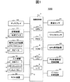
図1は、第一実施形態に係る車両警告装置100の概略構成図である。同図に示すように、車両警告装置100は、演算処理部1と、ディスプレイ10と、記憶装置11と、音声入出力装置13と、入力装置16と、ROM装置20と、車速センサ21と、ジャイロセンサ22と、GPS受信装置23と、FM多重放送受信装置24と、ビーコン受信装置25と、を有している。   FIG. 1 is a schematic configuration diagram of a vehicle warning device 100 according to the first embodiment. As shown in the figure, the vehicle warning device 100 includes an arithmetic processing unit 1, a display 10, a storage device 11, a voice input / output device 13, an input device 16, a ROM device 20, a vehicle speed sensor 21, It has a gyro sensor 22, a GPS receiver 23, an FM multiplex broadcast receiver 24, and a beacon receiver 25.

なお、車両警告装置100は、例えば、経路探索、交通情報の表示、探索経路によるユーザの誘導といったナビゲーション機能を備えるナビゲーション装置によって実現される。   Note that the vehicle warning device 100 is realized, for example, by a navigation device having a navigation function such as route search, traffic information display, and user guidance by the searched route.

演算処理部1は、車両警告装置100の様々な処理を行う中心的なユニットである。例えば、演算処理部1は、各種センサ21、22、GPS受信装置23、FM多重放送受信装置24などから出力される情報を用いて車両の現在地を検出する。また、演算処理部1は、検出された現在地を示す情報に基づいて、ディスプレイ10への表示に必要な地図データ12を記憶装置11あるいはROM装置20から読み出す。   The arithmetic processing unit 1 is a central unit that performs various processes of the vehicle warning device 100. For example, the arithmetic processing unit 1 detects the current location of the vehicle using information output from the various sensors 21 and 22, the GPS receiver 23, the FM multiplex broadcast receiver 24, and the like. In addition, the arithmetic processing unit 1 reads the map data 12 necessary for display on the display 10 from the storage device 11 or the ROM device 20 based on the information indicating the detected current location.

また、演算処理部1は、読み出した地図データ12をグラフィックス展開し、そこに現在地を示すマークを重ねてディスプレイ10へ出力する。また、記憶装置11あるいはROM装置20に記憶されている地図データ12などを用いて、現在地あるいはユーザから指示された出発地と、目的地(または、経由地や立ち寄り地)と、を結ぶ最適な経路(推奨経路)を探索する。また、演算処理部1は、所定の情報をスピーカ15やディスプレイ10から出力し、ユーザを誘導する。   Further, the arithmetic processing unit 1 develops the read map data 12 in graphics, and superimposes a mark indicating the current location on the map data 12 and outputs it to the display 10. Further, using the map data 12 or the like stored in the storage device 11 or the ROM device 20, an optimal connection between the current location or the departure location instructed by the user and the destination (or transit location or stopover location) is performed. Search for a route (recommended route). The arithmetic processing unit 1 outputs predetermined information from the speaker 15 or the display 10 to guide the user.

また、演算処理部1は、後述するように、ログ情報生成処理および第一警告判定処理を実行する。   In addition, the arithmetic processing unit 1 executes a log information generation process and a first warning determination process as will be described later.

なお、車両警告装置100の演算処理部1は、各デバイス間をバス7で接続した構成である。演算処理部1は、数値演算および各デバイスを制御するなどの処理を実行するCPU(Central Processing Unit)2と、記憶装置11から読み出した地図データ12や演算データなどを格納するRAM(Random Access Memory)3と、プログラムやデータを格納するROM(Read Only Memory)4と、演算データなどを書き換え可能な不揮発性のフラッシュメモリ5と、各種ハードウェアを演算処理部1と接続するためのI/F(インターフェース)6と、を有している。   The arithmetic processing unit 1 of the vehicle warning device 100 has a configuration in which each device is connected by a bus 7. The arithmetic processing unit 1 includes a CPU (Central Processing Unit) 2 that executes processing such as numerical calculation and control of each device, and a RAM (Random Access Memory) that stores map data 12 and arithmetic data read from the storage device 11. ) 3, a ROM (Read Only Memory) 4 for storing programs and data, a non-volatile flash memory 5 capable of rewriting arithmetic data, and an I / F for connecting various hardware to the arithmetic processing unit 1 (Interface) 6.

図2は、フラッシュメモリ5に記憶されているログ情報200を示したものである。ログ情報200は、各レコード201に、レコードの生成時刻202と駆動ステータス203とが対応付けられて格納されている。   FIG. 2 shows log information 200 stored in the flash memory 5. The log information 200 stores each record 201 in association with a record generation time 202 and a drive status 203.

ここで、駆動ステータスとは、パーキング(P)、ニュートラル(N)、ドライブ(D)、リバース(R)といった車両の駆動状態(停止状態を含む)を示すステータスのことである。   Here, the drive status is a status indicating a driving state (including a stop state) of the vehicle such as parking (P), neutral (N), drive (D), and reverse (R).

レコードの生成時刻202には、該当するレコード201が生成された時刻が格納される。また、駆動ステータス203には、後述するログ情報生成処理により、ドライブ(D)またはリバース(R)のいずれかが格納される。   The record generation time 202 stores the time when the corresponding record 201 was generated. The drive status 203 stores either drive (D) or reverse (R) by log information generation processing described later.

なお、各レコード201は、車速センサ21から出力されるパルス信号を演算処理部1が受信したタイミングで生成される。また、生成されたレコード201が所定数(例えば、20個)に達すると、古いレコードから順に削除されるとともに、新たなレコード201が生成される。   Each record 201 is generated at a timing when the arithmetic processing unit 1 receives a pulse signal output from the vehicle speed sensor 21. When the number of generated records 201 reaches a predetermined number (for example, 20), the old records are deleted in order and a new record 201 is generated.

このように、車速センサから出力されるパルス信号が示す所定距離(例えば、20cm)を移動すると、その時刻が対応付けられた1つのレコード201が新たに生成されることになる。また、駆動ステータス203には、レコード201が生成されたタイミングで検出された駆動ステータス203が格納される。   As described above, when a predetermined distance (for example, 20 cm) indicated by the pulse signal output from the vehicle speed sensor is moved, one record 201 associated with the time is newly generated. The drive status 203 stores the drive status 203 detected at the timing when the record 201 is generated.

図1に戻って説明する。ディスプレイ10は、演算処理部1などで生成されたグラフィックス情報を表示するユニットである。ディスプレイ10は、液晶ディスプレイ、有機ELディスプレイなどで構成される。   Returning to FIG. The display 10 is a unit that displays graphics information generated by the arithmetic processing unit 1 or the like. The display 10 is configured by a liquid crystal display, an organic EL display, or the like.

記憶装置11は、例えば、HDD(Hard Disk Drive)や不揮発性メモリなど、少なくとも読み書きが可能な記録媒体で構成される。また、例えば、HDDには地図データ12が記憶されている。   The storage device 11 is composed of at least a readable / writable recording medium such as an HDD (Hard Disk Drive) or a nonvolatile memory. For example, map data 12 is stored in the HDD.

音声入出力装置13は、音声入力装置としてマイクロフォン14を備え、音声出力装置としてスピーカ15を備える。マイクロフォン14は、使用者などが発した声など、車両警告装置100の外部の音声を取得する。また、スピーカ15は、演算処理部1で生成されたメッセージを音声信号として出力する。   The voice input / output device 13 includes a microphone 14 as a voice input device and a speaker 15 as a voice output device. The microphone 14 acquires sound outside the vehicle warning device 100 such as a voice uttered by a user or the like. The speaker 15 outputs the message generated by the arithmetic processing unit 1 as an audio signal.

入力装置16は、使用者からの指示を使用者による操作を介して受け付ける装置である。入力装置16は、例えば、方向キー17、ダイヤルスイッチ18、タッチパネル19、その他のハードスイッチ(縮尺変更キーなど)で構成される。   The input device 16 is a device that receives an instruction from the user through an operation by the user. The input device 16 includes, for example, a direction key 17, a dial switch 18, a touch panel 19, and other hard switches (such as a scale change key).

ROM装置20は、CD−ROMやDVD−ROMなどのROMや、IC(Integrated Circuit)カードといった、少なくとも読み取りが可能な記憶媒体で構成されている。このような記憶媒体には、例えば、動画データや、音声データなどが記憶されている。   The ROM device 20 includes at least a readable storage medium, such as a ROM such as a CD-ROM or a DVD-ROM, or an IC (Integrated Circuit) card. In such a storage medium, for example, moving image data, audio data, and the like are stored.

車速センサ21、ジャイロセンサ22、GPS受信装置23は、車両警告装置100で車両の現在地を検出するために使用されるものである。   The vehicle speed sensor 21, the gyro sensor 22, and the GPS receiver 23 are used by the vehicle warning device 100 to detect the current location of the vehicle.

車速センサ21は、検出した車輪の回転数をパルス信号に変換し、所定の時間内に検出したパルス信号数から車両の車速を算出する。   The vehicle speed sensor 21 converts the detected rotation number of the wheel into a pulse signal, and calculates the vehicle speed of the vehicle from the number of pulse signals detected within a predetermined time.

ジャイロセンサ22は、光ファイバジャイロや振動ジャイロ等で構成され、車両の回転による角速度を検出する。   The gyro sensor 22 is configured by an optical fiber gyro, a vibration gyro, or the like, and detects an angular velocity due to rotation of the vehicle.

GPS受信装置23は、GPS衛星からの信号を受信して、車両とGPS衛星間の距離と、距離の変化率を3個以上の衛星に対して測定することで、車両の現在地、進行速度および進行方位を算出する。   The GPS receiver 23 receives a signal from a GPS satellite, and measures the distance between the vehicle and the GPS satellite and the rate of change of the distance with respect to three or more satellites. Advancing direction is calculated.

FM多重放送受信装置24は、FM放送局から送られてくるFM多重放送信号を受信する。なお、FM多重放送には、VICS(Vehicle Information Communication System:登録商標)情報の概略現況交通情報、規制情報、SA/PA(サービスエリア/パーキングエリア)情報、駐車場情報、天気情報などや、FM多重一般情報としてラジオ局が提供する文字情報などがある。   The FM multiplex broadcast receiver 24 receives an FM multiplex broadcast signal sent from an FM broadcast station. Note that FM multiplex broadcasting includes VICS (Vehicle Information Communication System) information outline current traffic information, regulatory information, SA / PA (service area / parking area) information, parking lot information, weather information, etc. Multiplexed general information includes text information provided by radio stations.

ビーコン受信装置25は、光ビーコン、電波ビーコン等の信号を受信する。なお、ビーコン等の信号には、VICS情報の概略現況交通情報、規制情報、SA/PA(サービスエリア/パーキングエリア)情報、駐車場情報などがある。   The beacon receiving device 25 receives signals such as an optical beacon and a radio beacon. Signals such as beacons include VICS information outline current traffic information, regulation information, SA / PA (service area / parking area) information, and parking lot information.

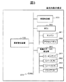
図3は、車両内部の構成を示した図である。同図に示すように、車両警告装置100は、車両の内部ネットワークであるCAN(Controller Area Network)370を介して車両制御部300に接続される。また、車両制御部300は、CAN370を介してECU350(エンジンコントロールユニット)および駆動ステータス統合部360に接続され、相互にデータ伝送が可能となっている。   FIG. 3 is a diagram showing a configuration inside the vehicle. As shown in the figure, the vehicle warning device 100 is connected to the vehicle control unit 300 via a CAN (Controller Area Network) 370 that is an internal network of the vehicle. In addition, the vehicle control unit 300 is connected to the ECU 350 (engine control unit) and the drive status integration unit 360 via the CAN 370 and can transmit data to each other.

車両制御部300は、車両全体の制御に関する処理を行う。例えば、車両制御部300は、ECU350や駆動ステータス統合部360との間で所定の情報をやり取りし、車両の様々な制御を実行する。   The vehicle control unit 300 performs processing related to control of the entire vehicle. For example, the vehicle control unit 300 exchanges predetermined information with the ECU 350 and the drive status integration unit 360 to execute various controls of the vehicle.

また、車両制御部300は、ユーザがアクセルペダルを踏み込んだことを示す情報をECU350から取得する。   In addition, vehicle control unit 300 acquires information indicating that the user has depressed the accelerator pedal from ECU 350.

また、車両制御部300は、駆動ステータスに関する情報を駆動ステータス統合部360から取得し、所定のログ情報を生成する。具体的には、車両制御部300は、図4に示すログ情報320を生成する。   In addition, the vehicle control unit 300 acquires information related to the drive status from the drive status integration unit 360, and generates predetermined log information. Specifically, the vehicle control unit 300 generates log information 320 shown in FIG.

ログ情報320には、各レコード321に、レコードの生成時刻322と、駆動ステータス323と、駆動ステータス323が検出されていた時間長さ324と、が対応付けられて格納されている。ここで、生成時刻322には、レコード321が生成された時刻が格納される。また、駆動ステータス323には、パーキング(P)、ニュートラル(N)、ドライブ(D)、リバース(R)のいずれかが格納される。また、検出時間長さ324には、かかる駆動ステータス323が検出されていた時間の長さが格納される。このようなログ情報320は、車両制御部が有するフラッシュメモリ(図示せず)などに記憶される。   In the log information 320, the record generation time 322, the drive status 323, and the time length 324 in which the drive status 323 was detected are stored in association with each record 321. Here, the generation time 322 stores the time when the record 321 was generated. In the drive status 323, parking (P), neutral (N), drive (D), or reverse (R) is stored. The detection time length 324 stores the length of time during which the drive status 323 has been detected. Such log information 320 is stored in a flash memory (not shown) included in the vehicle control unit.

なお、ログ情報320は、駆動ステータス統合部360から所定のタイミング(例えば、駆動ステータス統合部360が新たな駆動ステータスを検出したタイミングなど)で出力される駆動ステータスに関する情報を車両制御部300が取得した場合に生成される。   Note that the log information 320 is acquired by the vehicle control unit 300 from the drive status integration unit 360 with respect to the drive status output at a predetermined timing (for example, when the drive status integration unit 360 detects a new drive status). Generated when

また、ログ情報320は、生成されたレコード321が所定数(例えば、100個)に達すると、古いレコードから順に削除されるとともに、新たなレコード321が生成される。   In addition, when the number of generated records 321 reaches a predetermined number (for example, 100), the log information 320 is deleted in order from the oldest record, and a new record 321 is generated.

ECU350は、エンジン351の動作に関する制御を行う。例えば、ECU350は、エンジン351の始動指示を受け付けると、セルモータの回転によりエンジン351を始動させる。また、ECU350は、アクセルペダル352の踏み込み量に応じてエンジン351の回転数を制御する。   The ECU 350 performs control related to the operation of the engine 351. For example, upon receiving an instruction to start engine 351, ECU 350 starts engine 351 by the rotation of the cell motor. ECU 350 controls the number of revolutions of engine 351 in accordance with the amount of depression of accelerator pedal 352.

駆動ステータス統合部360は、駆動ステータスを検出し、これを車両制御部300に出力する。具体的には、駆動ステータス統合部360は、検出した駆動ステータスと、駆動ステータスが検出されていた時間の長さと、を含む所定の情報を車両制御部300に出力する。なお、駆動ステータス統合部360は、新たな駆動ステータスの検出時に所定の情報を車両制御部300に出力する。   The drive status integration unit 360 detects the drive status and outputs it to the vehicle control unit 300. Specifically, the drive status integration unit 360 outputs predetermined information including the detected drive status and the length of time during which the drive status was detected to the vehicle control unit 300. Drive status integration unit 360 outputs predetermined information to vehicle control unit 300 when a new drive status is detected.

次に、第一実施形態に係る車両警告装置100の機能ブロックについて説明する。なお、車両警告装置100の各機能ブロックは、演算処理部1に実装されるCPU2が読み込んだ所定のプログラムを実行することにより構築される。そのため、ROM4には、各機能部の処理を実行するためのプログラムが記憶されている。   Next, functional blocks of the vehicle warning device 100 according to the first embodiment will be described. Each functional block of the vehicle warning device 100 is constructed by executing a predetermined program read by the CPU 2 installed in the arithmetic processing unit 1. Therefore, the ROM 4 stores a program for executing processing of each functional unit.

また、車両警告装置100の各機能ブロックは、第一実施形態において実現される車両警告装置100の各機能を理解容易にするために、主な処理内容に応じて分類したものである。また、各機能の分類の仕方やその名称によって、本発明が制限されることはない。なお、車両警告装置100の各構成は、処理内容に応じて、さらに多くの構成要素に分類することもできる。また、一つの構成要素がさらに多くの処理を実行するように分類することもできる。   Each functional block of the vehicle warning device 100 is classified according to the main processing contents in order to facilitate understanding of each function of the vehicle warning device 100 realized in the first embodiment. Further, the present invention is not limited by the classification method of each function or its name. In addition, each structure of the vehicle warning apparatus 100 can also be classified into many more components according to the processing content. Moreover, it can also classify | categorize so that one component may perform more processes.

また、車両警告装置100の機能部は、ハードウェア(ASICなど)により構築されてもよい。また、各機能部の処理が一つのハードウェアで実行されてもよいし、複数のハードウェアで実行されてもよい。   Further, the functional unit of the vehicle warning device 100 may be constructed by hardware (ASIC or the like). Further, the processing of each functional unit may be executed by one hardware or may be executed by a plurality of hardware.

図5は、車両警告装置100の機能ブロックを示した図である。車両警告装置100は、情報制御部401と、ログ情報生成部402と、警告判定部403と、を有している。そして、車両警告装置100は、これらの各機能部や他のセンサなどの協働により所定の処理を実行する。   FIG. 5 is a diagram illustrating functional blocks of the vehicle warning device 100. The vehicle warning device 100 includes an information control unit 401, a log information generation unit 402, and a warning determination unit 403. And the vehicle warning device 100 performs a predetermined | prescribed process by cooperation of these each function parts, another sensor, etc.

情報制御部401は、様々な処理を行う中心的な機能部であり、処理内容に応じて、他の処理部を制御する。また、情報制御部401は、音声入出力装置13、入力装置16、各種センサ21、22から所定の情報や指示を受け付ける機能部である。また、情報制御部401は、取得した情報や受け付けた指示を、その種類や内容に応じて、所定の機能部に出力する機能部である。   The information control unit 401 is a central functional unit that performs various processes, and controls other processing units according to the processing content. The information control unit 401 is a functional unit that receives predetermined information and instructions from the voice input / output device 13, the input device 16, and the various sensors 21 and 22. The information control unit 401 is a functional unit that outputs acquired information and received instructions to a predetermined functional unit according to the type and content thereof.

また、情報制御部401は、各種センサ21、22、GPS受信装置23から出力される情報を用いて、マップマッチング処理を行い、現在地と車両の正面が向いている方向である車両方位を特定する。また、情報制御部401は、走行した日付、時刻、位置、を対応付けて走行履歴を記憶装置11に記憶する。また、情報制御部401は、現在地またはユーザから指示された出発地と、目的地とを結ぶ推奨経路を探索し、かかる経路や交通情報をグラフィックス変換してディスプレイ10に出力する。   In addition, the information control unit 401 performs map matching processing using information output from the various sensors 21 and 22 and the GPS receiver 23, and specifies the vehicle direction that is the direction in which the current location and the front of the vehicle are facing. . Further, the information control unit 401 stores the travel history in the storage device 11 in association with the date, time, and position of travel. In addition, the information control unit 401 searches for a recommended route that connects the current location or the departure location instructed by the user and the destination, converts the route and traffic information into graphics, and outputs the converted information to the display 10.

また、情報制御部401は、所定のタイミング(例えば、1秒ごと)で車両制御部300が生成したログ情報320を取得する。また、情報制御部401は、取得したログ情報320の最新レコード321が示す駆動ステータス323がパーキング(P)である場合、警告判定処理の開始を指示する信号を警告判定部403に出力する。   Further, the information control unit 401 acquires the log information 320 generated by the vehicle control unit 300 at a predetermined timing (for example, every second). Further, when the drive status 323 indicated by the latest record 321 of the acquired log information 320 is parking (P), the information control unit 401 outputs a signal instructing the start of the warning determination process to the warning determination unit 403.

ログ情報生成部402は、ログ情報200を生成する機能部である。具体的には、ログ情報生成部402は、生成時刻202と、駆動ステータス203と、が対応付けられている所定数(例えば、20個)のレコード201からなるログ情報200を生成する。   The log information generation unit 402 is a functional unit that generates the log information 200. Specifically, the log information generation unit 402 generates log information 200 including a predetermined number (for example, 20) of records 201 in which the generation time 202 and the drive status 203 are associated with each other.

警告判定部403は、警告判定処理を実行する機能部である。具体的には、警告判定部403は、ログ情報200に記録されている最新の駆動ステータス203と、警告判定処理を開始した後に検出された駆動ステータス323と、に基づいて警告を出力するか否かを判定する。   The warning determination unit 403 is a functional unit that executes warning determination processing. Specifically, the warning determination unit 403 determines whether to output a warning based on the latest drive status 203 recorded in the log information 200 and the drive status 323 detected after the warning determination process is started. Determine whether.

また、警告判定部403は、アクセルペダル352が踏み込まれたか否かに応じて、所定の処理を実行する。   Further, the warning determination unit 403 executes a predetermined process depending on whether or not the accelerator pedal 352 is depressed.

[動作の説明]次に、第一実施形態に係る車両警告装置100のログ情報生成処理について具体的に説明する。図6は、ログ情報生成処理を示したフロー図である。また、図8は、かかる処理の具体例を示した図である。 [Description of Operation] Next, the log information generation processing of the vehicle warning device 100 according to the first embodiment will be described in detail. FIG. 6 is a flowchart showing log information generation processing. FIG. 8 is a diagram showing a specific example of such processing.

なお、ログ情報生成処理は、車両警告装置100の起動により開始される。   The log information generation process is started when the vehicle warning device 100 is activated.

ログ情報生成部402は、駆動ステータスを取得する(ステップS001)。具体的には、ログ情報生成部402は、車速センサ21から出力されるパルス信号を受信すると、その時点における最新の駆動ステータスを車両制御部300から取得する。   The log information generation unit 402 acquires the drive status (step S001). Specifically, when receiving the pulse signal output from the vehicle speed sensor 21, the log information generation unit 402 acquires the latest drive status at that time from the vehicle control unit 300.

また、駆動ステータスを取得したログ情報生成部402は、パルス信号を受信した時刻202と、取得した駆動ステータス203とを対応付けたレコード201を有するログ情報200を生成し、フラッシュメモリ5に出力する(ステップS002)。なお、時刻の特定は、例えば内蔵するタイマー(図示せず)によって特定されればよい。   In addition, the log information generation unit 402 that has acquired the drive status generates log information 200 having a record 201 in which the time 202 at which the pulse signal is received and the acquired drive status 203 are associated with each other, and outputs the log information 200 to the flash memory 5. (Step S002). The time may be specified by, for example, a built-in timer (not shown).

このように、ログ情報生成部402は、ステップS001およびステップS002の処理を繰り返し実行し、所定数(例えば、20個)のレコード201を有するログ情報200を生成し続ける。   As described above, the log information generation unit 402 repeatedly executes the processes in steps S001 and S002, and continues to generate the log information 200 having a predetermined number (for example, 20) of records 201.

ここで、図8に示す具体例は、所定の駐車エリアに向かって車両が前進して進入し、停車している車両を示している。この場合、ログ情報200のレコード204〜レコード207は、車両が所定距離(例えば、20cm)進むごとに生成され、かかるタイミングで検出された駆動ステータス203が記録されている。具体的には、車両は駐車エリアに停車するまで前進していることから、レコード204〜レコード207の駆動ステータス203にはドライブ(D)が記録されることになる。   Here, the specific example shown in FIG. 8 shows a vehicle that has moved forward toward a predetermined parking area and has stopped. In this case, the records 204 to 207 of the log information 200 are generated every time the vehicle travels a predetermined distance (for example, 20 cm), and the drive status 203 detected at such timing is recorded. Specifically, since the vehicle is moving forward until it stops in the parking area, the drive (D) is recorded in the drive status 203 of record 204 to record 207.

なお、停車時には車軸が回転しないため、車速センサ21からパルス信号は出力されない。そのため、ログ情報200が有する最新のレコード207には、停車直前の駆動ステータス(図8では、ドライブ(D)208)が記録される。   Since the axle does not rotate when the vehicle is stopped, no pulse signal is output from the vehicle speed sensor 21. Therefore, the latest record 207 included in the log information 200 records the drive status (drive (D) 208 in FIG. 8) immediately before stopping.

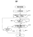
次に、警告判定処理について説明する。図7は、警告判定処理を示したフロー図である。また、図8は、かかる処理の具体例を示した図である。なお、警告判定処理は、駆動ステータス203がパーキング(P)であることを示す情報を取得した情報制御部401からの指示に基づき、警告判定部403によって開始される。すなわち、警告判定処理は、車両の停止状態が検出されると開始される。   Next, the warning determination process will be described. FIG. 7 is a flowchart showing the warning determination process. FIG. 8 is a diagram showing a specific example of such processing. The warning determination process is started by the warning determination unit 403 based on an instruction from the information control unit 401 that has acquired information indicating that the drive status 203 is parking (P). That is, the warning determination process is started when a stop state of the vehicle is detected.

警告判定部403は、フラッシュメモリ5に格納されているログ情報200を取得する(ステップS011)。また、警告判定部403は、ログ情報200の最新レコード201に記憶されている駆動ステータス203を抽出する(ステップS012)。すなわち、警告判定部403は、停車直前における車両の駆動ステータス203(図8では、最新レコード207のドライブ(D)208)を抽出する。   The warning determination unit 403 acquires the log information 200 stored in the flash memory 5 (step S011). Further, the warning determination unit 403 extracts the drive status 203 stored in the latest record 201 of the log information 200 (step S012). That is, the warning determination unit 403 extracts the drive status 203 of the vehicle immediately before stopping (the drive (D) 208 of the latest record 207 in FIG. 8).

ログ情報200から最新の駆動ステータス203を抽出すると、警告判定部403は、新たな駆動ステータスを検出したか否かを判定する(ステップS013)。具体的には、警告判定部403は、所定のタイミング(例えば、0.5秒〜1.0秒の間で所定の間隔)で車両制御部300により生成されたログ情報320を取得する。   When the latest drive status 203 is extracted from the log information 200, the warning determination unit 403 determines whether a new drive status has been detected (step S013). Specifically, the warning determination unit 403 acquires the log information 320 generated by the vehicle control unit 300 at a predetermined timing (for example, a predetermined interval between 0.5 seconds and 1.0 seconds).

また、警告判定部403は、ログ情報320の中から、パーキング(P)が格納されているレコード321よりも新しいレコードであって、検出時間長さ324が所定時間以上(例えば、0.5秒以上)のレコードを特定する。そして、警告判定部403は、所定時間以上の検出時間長さが格納されたレコード321の駆動ステータス323がドライブ(D)またはリバース(R)のいずれかであるか否かを判定する。   Further, the warning determination unit 403 is a newer record than the record 321 in which parking (P) is stored in the log information 320, and the detection time length 324 is equal to or longer than a predetermined time (for example, 0.5 seconds). Identify the above records. Then, the warning determination unit 403 determines whether the drive status 323 of the record 321 in which the detection time length equal to or longer than the predetermined time is stored is either drive (D) or reverse (R).

特定したレコードの駆動ステータス323がドライブ(D)またはリバース(R)のいずれかである場合、警告判定部403は、新たな駆動ステータスを検出したと判定し(ステップS013でYes)、処理をステップS014に移行する。   If the drive status 323 of the identified record is either drive (D) or reverse (R), the warning determination unit 403 determines that a new drive status has been detected (Yes in step S013), and the process is stepped. The process proceeds to S014.

一方で、所定時間以上の検出時間長さが格納されているレコード321がない場合、または、所定時間以上の検出時間長さが格納されたレコード321でも、駆動ステータス323がニュートラル(N)である場合、警告判定部403は、新たな駆動ステータスを検出していないと判定する(ステップS013でNo)。この場合、警告判定部403は、ステップS013の処理を繰り返し実行する。   On the other hand, when there is no record 321 storing a detection time length of a predetermined time or more, or even in a record 321 storing a detection time length of a predetermined time or more, the drive status 323 is neutral (N). In this case, the warning determination unit 403 determines that a new drive status has not been detected (No in step S013). In this case, the warning determination unit 403 repeatedly executes the process of step S013.

新たな駆動ステータスを検出すると、警告判定部403は、ステップS012で抽出した駆動ステータス203と、ステップS013で検出した駆動ステータス323と、が一致するか否かを判定する(ステップS014)。言い換えれば、警告判定部403は、停車直前の車両の移動方向(前進または後進)と、発車時の移動方向(前進または後進)と、が一致するか否かを判定する。   When a new drive status is detected, the warning determination unit 403 determines whether or not the drive status 203 extracted in step S012 matches the drive status 323 detected in step S013 (step S014). In other words, the warning determination unit 403 determines whether or not the moving direction (forward or reverse) of the vehicle immediately before stopping coincides with the moving direction (forward or reverse) at the time of departure.

図8の具体例では、ログ情報200の最新レコード207に記録されている駆動ステータス208がドライブ(D)であるため、新たに検出された駆動ステータス323がドライブ(D)と一致するか否かが判定される。   In the specific example of FIG. 8, since the drive status 208 recorded in the latest record 207 of the log information 200 is drive (D), whether or not the newly detected drive status 323 matches the drive (D). Is determined.

判定の結果、両者が一致する場合(ステップS014でYes)、警告判定部403は、所定の警告を示す情報を生成し、これをディスプレイ10やスピーカ15に出力する(ステップS015)。なお、所定の警告を示す情報は、ディスプレイ10に「WARNING」という文字を表示するための情報や、「衝突します、注意してください」という音声をスピーカ15から出力するための情報である。   As a result of the determination, if the two match (Yes in step S014), the warning determination unit 403 generates information indicating a predetermined warning and outputs the information to the display 10 and the speaker 15 (step S015). Note that the information indicating the predetermined warning is information for displaying the word “WARNING” on the display 10 or information for outputting the voice “Collision, please be careful” from the speaker 15.

一方で、ステップS012で抽出した駆動ステータス203と、ステップS013で検出された駆動ステータス323と、が一致しない場合(ステップS014でNo)、警告判定部403は、アクセルペダル352が踏み込まれたか否かを判定する(ステップS016)。   On the other hand, if the drive status 203 extracted in step S012 and the drive status 323 detected in step S013 do not match (No in step S014), the warning determination unit 403 determines whether or not the accelerator pedal 352 is depressed. Is determined (step S016).

そして、アクセルペダル352が踏み込まれたこと示す情報を車両制御部300から取得すると(ステップS016でYes)、警告判定部403は、警告判定処理を終了する。一方で、アクセルペダル352が踏み込まれたことを示す情報を取得しない場合(ステップS016でNo)、警告判定部403はステップS013の処理に戻る。   And if the information which shows that the accelerator pedal 352 was stepped on is acquired from the vehicle control part 300 (Yes in step S016), the warning determination part 403 will complete | finish a warning determination process. On the other hand, when information indicating that the accelerator pedal 352 has been depressed is not acquired (No in step S016), the warning determination unit 403 returns to the process of step S013.

以上、本発明の第一実施形態について説明した。   The first embodiment of the present invention has been described above.

このように、第一実施形態に係る車両警告装置では、車両の停車前の移動方向(前進または後進)と同じ方向に車両を発車させようとした場合に所定の警告が出力される。多くの場合、停車直前に特定される移動方向と同じ方向にはフェンスや壁といった障害物が存在し、その方向に発車すると衝突してしまう危険性が高い。   Thus, in the vehicle warning device according to the first embodiment, a predetermined warning is output when the vehicle is about to start in the same direction as the moving direction (forward or reverse) before the vehicle stops. In many cases, there are obstacles such as fences and walls in the same direction as the moving direction specified immediately before stopping, and there is a high risk of collision if the vehicle departs in that direction.

したがって、車両の停車前の移動方向と同じ方向に車両を発車させようとしたことを検出した場合に所定の警告を出力すれば、車両を動かす方向の間違いをより確実に防止することができる。特に、地図データから車両周辺にある障害物などを特定できない場合でも、移動方向の誤りによる衝突事故を回避することができる。   Therefore, if a predetermined warning is output when it is detected that the vehicle is about to start in the same direction as the moving direction before the vehicle stops, an error in the direction of moving the vehicle can be prevented more reliably. In particular, even when an obstacle around the vehicle cannot be identified from the map data, a collision accident due to an error in the moving direction can be avoided.

次に、本発明の第二実施形態に係る発明について説明する。ここで、本実施形態に係る車両警告装置100は、第一実施形態に係る車両警告装置100の構成とほぼ同様の構成を有している。したがって、車両警告装置100として共通する構成については説明を省略する。   Next, the invention according to the second embodiment of the present invention will be described. Here, the vehicle warning device 100 according to the present embodiment has substantially the same configuration as the configuration of the vehicle warning device 100 according to the first embodiment. Therefore, the description of the configuration common to the vehicle warning device 100 is omitted.

ここで、図9は、第二実施形態で用いられるログ情報220を示した図である。同図に示すように、各レコード221には、レコードの生成時刻222と、駆動ステータス223と、警告対象が存在するエリア224と、が対応付けられて格納されている。また、各レコード221は、第一実施形態のログ情報200と同様に、生成されたレコード221が所定数(例えば、20個)に達すると、古いレコードから順に削除されるとともに、新たなレコード221が生成される。   Here, FIG. 9 is a diagram showing the log information 220 used in the second embodiment. As shown in the figure, each record 221 stores a record generation time 222, a drive status 223, and an area 224 in which a warning target exists in association with each other. In addition, as with the log information 200 of the first embodiment, when the number of generated records 221 reaches a predetermined number (for example, 20), each record 221 is deleted in order from the old record, and a new record 221 is also created. Is generated.

ここで、警告対象が存在するエリア224には、車両の「前方エリア」または「後方エリア」のいずれかを示す情報が記録される。なお、警告対象が存在しない場合、何も記録されない。   Here, in the area 224 where the warning target exists, information indicating either the “front area” or the “rear area” of the vehicle is recorded. If there is no warning target, nothing is recorded.

また、地図データ12は、建物などの情報を3次元的に表現した、いわゆるポリゴンデータを有している。また、海や川など車両が立ち入ることのできない領域に関する情報は、進入禁止を示す情報と共に地図データ12に記憶されている。   The map data 12 has so-called polygon data that three-dimensionally expresses information such as buildings. Further, information relating to areas where vehicles cannot enter, such as the sea and rivers, is stored in the map data 12 together with information indicating entry prohibition.

なお、以下では、車両の前方エリアまたは後方エリアに存在するポリゴンデータや進入禁止を示す情報を有する地図データ12上の地点を「警告対象」と呼ぶ。   Hereinafter, a point on the map data 12 having information indicating polygon data or entry prohibition existing in the front area or the rear area of the vehicle is referred to as “warning target”.

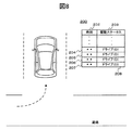
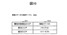
また、記憶装置11には、図10に示す駆動ステータス変換テーブル500が記憶されている。駆動ステータス変換テーブル500には、警告対象を検出したエリア(車両の前方エリアまたは後方エリア)501と、駆動ステータス502と、が対応付けられている。   Further, the storage device 11 stores a drive status conversion table 500 shown in FIG. In the drive status conversion table 500, an area (front area or rear area of the vehicle) 501 in which a warning target is detected and a drive status 502 are associated with each other.

また、図11に示すように、第二実施形態に係る車両警告装置100の機能ブロックは、情報制御部601と、ログ情報生成部602と、警告対象検出部603と、警告判定部604と、を有している。なお、情報制御部601およびログ情報生成部602は、第一実施形態と同様であるため、説明を省略する。   As shown in FIG. 11, the functional blocks of the vehicle warning device 100 according to the second embodiment include an information control unit 601, a log information generation unit 602, a warning target detection unit 603, a warning determination unit 604, have. Note that the information control unit 601 and the log information generation unit 602 are the same as those in the first embodiment, and a description thereof will be omitted.

警告対象検出部603は、警告対象検出処理を実行する機能部である。具体的には、警告対象検出部603は、車両方位に基づいて車両の前方エリアおよび後方エリアを決定し、かかるエリア内に存在する警告対象の検出を実行する。   The warning target detection unit 603 is a functional unit that executes warning target detection processing. Specifically, the warning target detection unit 603 determines a front area and a rear area of the vehicle based on the vehicle direction, and executes detection of a warning target existing in the area.

警告判定部604は、警告判定処理を実行する機能部である。具体的には、警告判定部604は、ログ情報220の駆動ステータス223と、警告判定処理を開始した後に検出された駆動ステータス323と、に基づいて警告を出力するか否かを判定する。   The warning determination unit 604 is a functional unit that executes warning determination processing. Specifically, the warning determination unit 604 determines whether or not to output a warning based on the drive status 223 of the log information 220 and the drive status 323 detected after the warning determination process is started.

また、警告判定部604は、アクセルペダル352が踏み込まれたか否かに応じて所定の処理を実行する。   Further, the warning determination unit 604 executes a predetermined process depending on whether or not the accelerator pedal 352 is depressed.

[動作の説明]次に、第二実施形態に係る車両警告装置100の警告対象検出処理について具体的に説明する。なお、ログ情報生成処理は、第一実施形態と同様であるため、説明を省略する。 [Description of Operation] Next, the warning object detection process of the vehicle warning device 100 according to the second embodiment will be described in detail. The log information generation process is the same as that in the first embodiment, and a description thereof will be omitted.

図12は、警告対象検出処理を示したフロー図である。また、図14、15は、かかる処理の具体例を示した図である。なお、警告対象検出処理は、車両警告装置100の起動により開始される。   FIG. 12 is a flowchart showing the warning target detection process. 14 and 15 are diagrams showing specific examples of such processing. Note that the warning target detection process is started when the vehicle warning device 100 is activated.

警告対象検出部603は、車両の前方エリアおよび後方エリアを決定する(ステップS021)。具体的には、図14、15に示すように、警告対象検出部603は、情報制御部601から取得した車両方位を示す情報に基づいて、車両の正面である前方(図14では前方701、図15では前方801)と、その逆側である後方(図14では前方702、図15では前方802)と、を特定する。   The warning target detection unit 603 determines a front area and a rear area of the vehicle (step S021). Specifically, as illustrated in FIGS. 14 and 15, the warning target detection unit 603 is based on information indicating the vehicle direction acquired from the information control unit 601, in front of the front of the vehicle (in FIG. 14, the front 701, In FIG. 15, the front side 801) and the rear side (the front side 702 in FIG. 14 and the front side 802 in FIG. 15) are specified.

また、警告対象検出部603は、特定した車両前方および後方に基づいて前方エリアおよび後方エリアを特定する。具体的には、図14、15に示すように、車両前方の所定範囲内(例えば、車両前端から3m四方の範囲)を前方エリア(図14では前方703、図15では前方803)に決定する。また、警告対象検出部603は、特定した車両後方の所定距離内(例えば、車両の後端から3m四方の範囲)を後方エリア(図14では前方704、図15では前方804)に決定する。   Further, the warning target detection unit 603 identifies the front area and the rear area based on the identified vehicle front and rear. Specifically, as shown in FIGS. 14 and 15, a predetermined area in front of the vehicle (for example, a range 3 m square from the front end of the vehicle) is determined as a front area (front 703 in FIG. 14 and front 803 in FIG. 15). . Further, the warning target detection unit 603 determines the rear area (front 704 in FIG. 14 and front 804 in FIG. 15) within a predetermined distance behind the specified vehicle (for example, a range of 3 m square from the rear end of the vehicle).

警告対象検出部603は、車両の前方エリアおよび後方エリアを決定すると、かかるエリアのどちらかに警告対象が存在するか検出を実行する(ステップS022)。具体的には、警告対象検出部603は、車両の前方エリアまたは後方エリアを示す地点座標に、ポリゴンデータや進入禁止領域といった警告対象が有する地点座標が含まれるか否かを判定する。   When the warning target detection unit 603 determines the front area and the rear area of the vehicle, the warning target detection unit 603 detects whether there is a warning target in either of these areas (step S022). Specifically, the warning target detection unit 603 determines whether or not the point coordinates indicating the front area or the rear area of the vehicle include the point coordinates of the warning target such as polygon data or an entry prohibition area.

そして、車両の前方エリアまたは後方エリアを示す地点座標に、警告対象の地点座標が含まれる場合(ステップS022でYes)、警告対象検出部603は、警告対象が存在するエリア(車両の前方エリアまたは後方エリア)を特定する。   If the point coordinates indicating the front area or the rear area of the vehicle include the point coordinates of the warning target (Yes in step S022), the warning target detection unit 603 displays the area where the warning target exists (the front area of the vehicle or Identify the rear area.

図14の具体例では、警告対象(コンビニなどの建物など)705が車両の後方エリア704に存在することが特定される。また、図15の具体例では、警告対象(海などの進入禁止領域)805が車両の前方エリア803に存在することが特定される。   In the specific example of FIG. 14, it is specified that a warning target (a building such as a convenience store) 705 exists in the rear area 704 of the vehicle. Further, in the specific example of FIG. 15, it is specified that the warning target (entrance prohibited area such as the sea) 805 exists in the front area 803 of the vehicle.

車両の前方エリアまたは後方エリアのどちらかに警告対象が存在することを検出した警告対象検出部603は、警告対象の検出時に生成されているログ情報220が有する最新レコード221の警告対象が存在するエリア224に、「前方エリア」または「後方エリア」を記録する。   The warning target detection unit 603 that detects that a warning target exists in either the front area or the rear area of the vehicle has a warning target of the latest record 221 included in the log information 220 generated when the warning target is detected. In the area 224, “front area” or “rear area” is recorded.

例えば、図14の具体例では、車両はコンビニなどの建物705を後方にしてバック(後進)しているため、ログ情報220が有するレコード225〜レコード228の駆動ステータス223にはリバース(R)が記録されている。また、コンビニなどの施設705が後方エリア704内に含まれる位置まで車両が後進すると、かかる施設705は警告対象として検出され、検出時点で生成されているレコード227、228の警告対象が存在するエリア224には「後方エリア」が記録される。   For example, in the specific example of FIG. 14, the vehicle is backing (backward) with the building 705 such as a convenience store in the rear, so reverse (R) is displayed in the drive status 223 of the records 225 to 228 included in the log information 220. It is recorded. Further, when the vehicle moves backward to a position where the facility 705 such as a convenience store is included in the rear area 704, the facility 705 is detected as a warning target, and the warning target of the records 227 and 228 generated at the time of detection exists. In “224”, “rear area” is recorded.

また、図15の具体例では、車両は海805を前方にして前進しているため、ログ情報220が有するレコード230〜レコード233の駆動ステータス223にはドライブ(D)が記録される。また、海805が前方エリア803内に含まれる位置まで車両が前進すると、海805などの進入禁止領域は警告対象として検出され、検出時点で生成されているレコード231〜レコード233の警告対象が存在するエリア224には「前方エリア」が記録される。   In the specific example of FIG. 15, since the vehicle is moving forward with the sea 805 forward, the drive (D) is recorded in the drive status 223 of the record 230 to the record 233 included in the log information 220. Further, when the vehicle moves forward to a position where the sea 805 is included in the front area 803, the entry prohibition area such as the sea 805 is detected as a warning target, and there are warning targets of the records 231 to 233 generated at the time of detection. In the area 224, the “front area” is recorded.

一方で、前方エリアまたは後方エリアの地点座標に警告対象の地点座標が含まれない場合(ステップS022でNo)、警告対象検出部603は、ステップS021に処理を戻す。なお、この場合、レコード221の警告対象が存在するエリア224には何も記録されない。   On the other hand, when the point coordinates of the warning target are not included in the point coordinates of the front area or the rear area (No in step S022), the warning target detection unit 603 returns the process to step S021. In this case, nothing is recorded in the area 224 where the warning target of the record 221 exists.

次に、図13を用いて警告判定処理について説明する。警告判定処理は、駆動ステータス323がパーキング(P)であることを示す情報を取得した情報制御部601からの指示に基づき、警告判定部604によって開始される。すなわち、警告判定処理は、車両の停止状態が検出されると開始される。   Next, the warning determination process will be described with reference to FIG. The warning determination process is started by the warning determination unit 604 based on an instruction from the information control unit 601 that has acquired information indicating that the drive status 323 is parking (P). That is, the warning determination process is started when a stop state of the vehicle is detected.

まず、警告判定部604は、フラッシュメモリ5に記憶されているログ情報220を取得する(ステップS031)。   First, the warning determination unit 604 acquires the log information 220 stored in the flash memory 5 (step S031).

ログ情報220を取得した警告判定部604は、車両の前方エリアまたは後方エリアに警告対象が存在するか否かを判定する(ステップS032)。具体的には、警告判定部604は、取得したログ情報220の最新レコード221を参照し、警告対象が存在するエリア224に「前方エリア」または「後方エリア」が記録されているか否かを判定する。そして、「前方エリア」または「後方エリア」のいずれかが記録されている場合(ステップS032でYes)、警告判定部604は、かかるエリアを抽出し、処理をステップS033に移行する。   The warning determination unit 604 that acquired the log information 220 determines whether there is a warning target in the front area or the rear area of the vehicle (step S032). Specifically, the warning determination unit 604 refers to the latest record 221 of the acquired log information 220 and determines whether “front area” or “rear area” is recorded in the area 224 where the warning target exists. To do. If either “front area” or “rear area” is recorded (Yes in step S032), the warning determination unit 604 extracts the area, and the process proceeds to step S033.

一方で、警告対象が存在するエリア224に何も記録されていない場合(ステップS032でNo)、すなわち、車両の前方エリアおよび後方エリアのどちら側にも警告対象が存在しない場合、警告判定部604は、警告判定処理を終了する。   On the other hand, when nothing is recorded in the area 224 where the warning target exists (No in step S032), that is, when there is no warning target on either the front area or the rear area of the vehicle, the warning determination unit 604 Ends the warning determination process.

車両の前方エリアまたは後方エリアのいずれかに警告対象が存在すると判定した警告判定部604は、前方エリア(または後方エリア)を駆動ステータスに変換する。   The warning determination unit 604 that has determined that there is a warning target in either the front area or the rear area of the vehicle converts the front area (or the rear area) into a drive status.

具体的には、警告判定部604は、駆動ステータス変換テーブル500を参照して、ステップS032で抽出したエリア501(前方エリアまたは後方エリア)に対応付けられている駆動ステータス502を取得する。すなわち、抽出したエリアが「前方エリア」である場合、警告判定部604は、ドライブ(D)を取得する。一方で、抽出したエリアが「後方エリア」である場合、警告判定部604は、リバース(R)を取得する。   Specifically, the warning determination unit 604 refers to the drive status conversion table 500 and acquires the drive status 502 associated with the area 501 (front area or rear area) extracted in step S032. That is, when the extracted area is the “front area”, the warning determination unit 604 acquires the drive (D). On the other hand, when the extracted area is the “rear area”, the warning determination unit 604 acquires reverse (R).

図14の具体例では、ログ情報220が有する最新レコード228の警告対象が存在するエリア224には、「後方エリア」が記録されている。この場合、警告判定部604は、駆動ステータス変換テーブル500を用いて、「後方エリア」に対応付けられている「リバース(R)」を取得する。   In the specific example of FIG. 14, “rear area” is recorded in the area 224 where the warning target of the latest record 228 included in the log information 220 exists. In this case, the warning determination unit 604 uses the drive status conversion table 500 to acquire “reverse (R)” associated with “rear area”.

また、図15の具体例では、ログ情報220が有する最新レコード233の警告対象が存在するエリア224には、「前方エリア」が記録されている。この場合、警告判定部604は、駆動ステータス変換テーブル500を用いて、「前方エリア」に対応付けられている「ドライブ(D)」を取得する。   Further, in the specific example of FIG. 15, “front area” is recorded in the area 224 where the warning target of the latest record 233 included in the log information 220 exists. In this case, the warning determination unit 604 uses the drive status conversion table 500 to acquire “drive (D)” associated with “front area”.

駆動ステータス変換テーブル500を用いて所定の駆動ステータス502を取得した警告判定部604は、新たな駆動ステータスを検出したか否かを判定する(ステップS034)。具体的には、警告判定部604は、所定のタイミング(例えば、0.5秒〜1.0秒の間で所定の間隔)で車両制御部300により生成されたログ情報320を取得する。   The warning determination unit 604 that has acquired the predetermined drive status 502 using the drive status conversion table 500 determines whether a new drive status has been detected (step S034). Specifically, the warning determination unit 604 acquires the log information 320 generated by the vehicle control unit 300 at a predetermined timing (for example, a predetermined interval between 0.5 seconds and 1.0 seconds).

また、警告判定部604は、ログ情報320の中で、パーキング(P)が格納されているレコードよりも新しいレコード321であって、検出時間長さ324が所定時間以上(例えば、0.5秒以上)のレコードを特定する。そして、警告判定部604は、所定時間以上の検出時間長さが格納されたレコード321の駆動ステータス323がドライブ(D)またはリバース(R)のいずれかであるか否かを判定する。   Further, the warning determination unit 604 is a record 321 newer than the record in which parking (P) is stored in the log information 320, and the detection time length 324 is equal to or longer than a predetermined time (for example, 0.5 seconds). Identify the above records. The warning determination unit 604 determines whether the drive status 323 of the record 321 in which the detection time length equal to or longer than the predetermined time is stored is either drive (D) or reverse (R).

特定したレコード321の駆動ステータス323がドライブ(D)またはリバース(R)のいずれかである場合、警告判定部604は、新たな駆動ステータスを検出したと判定し(ステップS034でYes)、処理をステップS035に移行する。   If the drive status 323 of the identified record 321 is either drive (D) or reverse (R), the warning determination unit 604 determines that a new drive status has been detected (Yes in step S034), and performs processing. The process proceeds to step S035.

一方で、所定時間以上の検出時間長さが格納されているレコードがない場合、または、所定時間以上の検出時間長さが格納されたレコード321でも、駆動ステータス323がニュートラル(N)である場合、警告判定部604は、新たな駆動ステータスを検出していないと判定する(ステップS034でNo)。この場合、警告判定部604は、ステップS034の処理を繰り返し実行する。   On the other hand, when there is no record in which the detection time length equal to or longer than the predetermined time is stored, or the drive status 323 is neutral (N) even in the record 321 in which the detection time length equal to or longer than the predetermined time is stored. The warning determination unit 604 determines that a new drive status has not been detected (No in step S034). In this case, the warning determination unit 604 repeatedly executes the process of step S034.

新たな駆動ステータスを検出すると、警告判定部604は、ステップS033で取得した駆動ステータス502と、ステップS034で検出した駆動ステータス323と、が一致するか否かを判定する(ステップS035)。言い換えれば、警告判定部604は、停車直前の車両の移動方向(前進または後進)と、発車時の移動方向(前進または後進)と、が一致するか否かを判定する。   When a new drive status is detected, the warning determination unit 604 determines whether or not the drive status 502 acquired in step S033 matches the drive status 323 detected in step S034 (step S035). In other words, the warning determination unit 604 determines whether or not the moving direction (forward or reverse) of the vehicle immediately before stopping coincides with the moving direction (forward or reverse) at the time of departure.

図14の具体例では、ステップS033で取得した駆動ステータス223がリバース(R)であるため、警告判定部604は、新たに検出した駆動ステータス323がリバース(R)と一致するか否かを判定する。   In the specific example of FIG. 14, since the drive status 223 acquired in step S033 is reverse (R), the warning determination unit 604 determines whether or not the newly detected drive status 323 matches reverse (R). To do.

また、図15の具体例では、ステップS033で取得した駆動ステータス223がドライブ(D)であるため、警告判定部604は、新たに検出した駆動ステータス323がドライブ(D)と一致するか否かを判定する。   In the specific example of FIG. 15, since the drive status 223 acquired in step S033 is drive (D), the warning determination unit 604 determines whether or not the newly detected drive status 323 matches the drive (D). Determine.

判定の結果、両者が一致する場合(ステップS035でYes)、警告判定部604は、所定の警告を示す情報を生成し、これをディスプレイ10やスピーカ15に出力する(ステップS036)。なお、所定の警告を示す情報とは、第一実施形態と同様であるため、説明を省略する。   As a result of the determination, if both match (Yes in step S035), the warning determination unit 604 generates information indicating a predetermined warning and outputs the information to the display 10 and the speaker 15 (step S036). Note that the information indicating the predetermined warning is the same as that in the first embodiment, and a description thereof will be omitted.

一方で、ステップS033で取得した駆動ステータス223と、ステップS034で検出した駆動ステータス323と、が一致しない場合(ステップS035でNo)、警告判定部604は、処理をステップS037に移行する。なお、ステップS037の処理は第一実施形態のステップS016と同様であるため、説明を省略する。   On the other hand, if the drive status 223 acquired in step S033 and the drive status 323 detected in step S034 do not match (No in step S035), the warning determination unit 604 proceeds to step S037. In addition, since the process of step S037 is the same as that of step S016 of 1st embodiment, description is abbreviate | omitted.

以上のような第二実施形態に係る発明によれば、車両を動かす方向の間違いをより確実に防止することができる。特に、本実施形態に係る発明では、ポリゴンデータを用いることにより、車両の前方エリアまたは後方エリア内にある警告対象を具体的に特定することができる。したがって、より高い精度で衝突回避の警告を出力することができる。   According to the invention according to the second embodiment as described above, an error in the direction of moving the vehicle can be prevented more reliably. In particular, in the invention according to the present embodiment, by using polygon data, it is possible to specifically specify a warning target in the front area or the rear area of the vehicle. Accordingly, a collision avoidance warning can be output with higher accuracy.

次に、本発明の第三実施形態に係る発明について説明する。ここで、本実施形態に係る車両警告装置100は、第二実施形態に係る車両警告装置100の構成とほぼ同様の構成を有している。したがって、車両警告装置100として共通する構成については説明を省略する。   Next, the invention according to the third embodiment of the present invention will be described. Here, the vehicle warning device 100 according to the present embodiment has substantially the same configuration as the configuration of the vehicle warning device 100 according to the second embodiment. Therefore, the description of the configuration common to the vehicle warning device 100 is omitted.

第三実施形態に係る記憶装置11には、3次元ポリゴンデータによって描かれた駐車場データを有している。   The storage device 11 according to the third embodiment has parking lot data drawn by three-dimensional polygon data.

また、図11に示すように、第三実施形態に係る車両警告装置100の機能ブロックは、第二実施形態の機能ブロックと同様に、情報制御部601と、ログ情報生成部602と、警告対象検出部603と、警告判定部604と、を有している。なお、情報制御部601と、ログ情報生成部602と、警告判定部604とは、第二実施形態と同様であるため、説明を省略する。   Further, as shown in FIG. 11, the functional blocks of the vehicle warning device 100 according to the third embodiment are the same as the functional blocks of the second embodiment, the information control unit 601, the log information generation unit 602, and the warning target. A detection unit 603 and a warning determination unit 604 are provided. Note that the information control unit 601, the log information generation unit 602, and the warning determination unit 604 are the same as those in the second embodiment, and thus description thereof is omitted.

警告対象検出部603は、警告対象検出処理を実行する機能部である。具体的には、警告対象検出部603は、車両方位に基づいて、車両の前方エリアおよび後方エリアを決定し、かかるエリア内に存在する警告対象の検出を実行する。また、警告対象検出部603は、前方エリアおよび後方エリアの両方に警告対象が存在することを検出した場合、警告対象により近いのが前方エリアであるのか、または、後方エリアであるのかを特定する。   The warning target detection unit 603 is a functional unit that executes warning target detection processing. Specifically, the warning target detection unit 603 determines a front area and a rear area of the vehicle based on the vehicle direction, and executes detection of a warning target existing in the area. In addition, when the warning target detection unit 603 detects that a warning target exists in both the front area and the rear area, the warning target detection unit 603 specifies whether the warning target is closer to the front area or the rear area. .

[動作の説明]次に、第三実施形態に係る車両警告装置100で実行される所定の処理について説明する。車両警告装置100は、ログ情報生成処理と、警告対象検出処理と、警告判定処理と、を実行する。なお、ログ情報生成処理は、第一実施形態の場合と同様であるため、説明を省略する。また、警告判定処理は、第二実施形態の場合と同様のであるため、説明を省略する。 [Description of Operation] Next, a predetermined process executed by the vehicle warning device 100 according to the third embodiment will be described. The vehicle warning device 100 executes log information generation processing, warning target detection processing, and warning determination processing. The log information generation process is the same as that in the first embodiment, and a description thereof will be omitted. Moreover, since the warning determination process is the same as that of the second embodiment, description thereof is omitted.

警告対象検出処理について具体的に説明する。図16は、警告対象検出処理を示したフロー図である。また、図17は、かかる処理の具体例を示した図である。なお、警告対象検出処理は、車両警告装置100の起動により開始される。   The warning target detection process will be specifically described. FIG. 16 is a flowchart showing the warning target detection process. FIG. 17 is a diagram showing a specific example of such processing. Note that the warning target detection process is started when the vehicle warning device 100 is activated.

警告対象検出部603は、車両の前方エリアおよび後方エリアを決定する(ステップS041)。具体的には、図17に示すように、警告対象検出部603は、情報制御部601から取得した車両方位を示す情報に基づいて、車両の正面である前方901と、その逆側である後方902と、を特定する。   The warning target detection unit 603 determines a front area and a rear area of the vehicle (step S041). Specifically, as illustrated in FIG. 17, the warning target detection unit 603 is based on the information indicating the vehicle orientation acquired from the information control unit 601, and the rear side is the front side 901 that is the front side of the vehicle. 902 is specified.

また、警告対象検出部603は、特定した車両前方および後方に基づいて前方エリアおよび後方エリアを特定する。具体的には、図17に示すように、警告対象検出部603は、車両前方の所定範囲内(例えば、車両前端から3m四方の範囲)を前方エリア903に決定する。また、警告対象検出部603は、特定した車両後方の所定範囲内(例えば、車両の後端から3m四方の範囲)を後方エリア904に決定する。   Further, the warning target detection unit 603 identifies the front area and the rear area based on the identified vehicle front and rear. Specifically, as illustrated in FIG. 17, the warning target detection unit 603 determines the front area 903 within a predetermined range in front of the vehicle (for example, a range 3 m square from the front end of the vehicle). Further, the warning target detection unit 603 determines the rear area 904 within a specified range behind the identified vehicle (for example, a range 3 m square from the rear end of the vehicle).

警告対象検出部603は、車両の前方エリア903および後方エリア904を決定すると、かかるエリアの両方に警告対象が存在するか検出を実行する(ステップS042)。具体的には、警告対象検出部603は、車両の前方エリア903および後方エリア904を示す地点座標に、ポリゴンデータや進入禁止領域といった警告対象が有する地点座標が含まれるか否かを判定する。   When the warning target detection unit 603 determines the front area 903 and the rear area 904 of the vehicle, the warning target detection unit 603 detects whether there is a warning target in both areas (step S042). Specifically, the warning target detection unit 603 determines whether or not the point coordinates indicating the front area 903 and the rear area 904 of the vehicle include the point coordinates of the warning target such as polygon data and entry prohibition areas.

そして、車両の前方エリア903および後方エリア904の各々の地点座標に、警告対象の地点座標が含まれる場合(ステップS042でYes)、すなわち、前方エリア903および後方エリア904の両方に警告対象が存在することを検出した場合、警告対象検出部603は、処理をステップS043に移行し、警告対象からより近いのが前方エリア903であるか、または後方エリア904であるか、を特定する。   If the point coordinates of the warning target are included in the point coordinates of the front area 903 and the rear area 904 of the vehicle (Yes in step S042), that is, there is a warning target in both the front area 903 and the rear area 904. When it is detected that the warning object is detected, the warning object detection unit 603 moves the process to step S043 and specifies whether the front area 903 or the rear area 904 is closer to the warning object.

具体的には、警告対象検出部603は、前方エリア903にある警告対象と車両の前端との間の距離を算出する。また、警告対象検出部603は、後方エリア904にある警告対象と車両の後端との間の距離を算出する。そして、警告対象検出部603は、算出した距離同士を比較し、警告対象からより近いのが車両の前方エリア903であるか、後方エリア904であるかを特定する。   Specifically, the warning target detection unit 603 calculates the distance between the warning target in the front area 903 and the front end of the vehicle. Further, the warning target detection unit 603 calculates the distance between the warning target in the rear area 904 and the rear end of the vehicle. Then, the warning target detection unit 603 compares the calculated distances, and specifies whether the vehicle front area 903 or the rear area 904 is closer to the warning target.

一方で、前方エリア903および後方エリア904の各々の地点座標に、警告対象の地点座標が含まれない場合(ステップS042でNo)、警告対象検出部603は、ステップS042の処理を繰り返し実行する。   On the other hand, when the point coordinates of the warning target are not included in the point coordinates of the front area 903 and the rear area 904 (No in step S042), the warning target detection unit 603 repeatedly executes the process of step S042.

図17の具体例では、車両は壁Bを後方にしてバック(後進)しているため、ログ情報220が有するレコード241〜243にはリバース(R)が記録される。また、車両が所定の位置まで来ると、壁Aおよび壁Bが各々、車両の前方エリア903および後方エリア904内に含まれる。そうすると、壁Aおよび壁Bは警告対象として検出され、かかる警告対象からより近いのが前方エリア903であるか、または、後方エリア904であるか、が特定される(ステップS043)。   In the specific example of FIG. 17, since the vehicle is backing (backward) with the wall B facing backward, reverse (R) is recorded in the records 241 to 243 included in the log information 220. When the vehicle reaches a predetermined position, wall A and wall B are included in the front area 903 and the rear area 904 of the vehicle, respectively. Then, the wall A and the wall B are detected as warning targets, and it is specified whether the front area 903 or the rear area 904 is closer to the warning target (step S043).

この場合、車両と壁Aとの距離はL1と算出される。また、車両と壁Bとの距離はL2と算出される。ここでL1>L2であることから、警告対象からより近いのは車両の後方エリア904であることが特定されることになる。   In this case, the distance between the vehicle and the wall A is calculated as L1. Further, the distance between the vehicle and the wall B is calculated as L2. Here, since L1> L2, it is specified that the vehicle closer to the warning object is the rear area 904 of the vehicle.

警告対象からより近いのが前方エリア903であるか、または後方エリア904であるか、を特定した警告対象検出部603は、特定したエリア(前方エリア903または後方エリア904)をログ情報220に記録する(ステップS044)。具体的には、警告対象検出部603は、警告対象の検出時に生成されているレコード221のうち、最新レコードの警告対象が存在するエリア224に「前方エリア」または「後方エリア」を記録する。   The warning object detection unit 603 that specified whether the area closer to the warning object is the front area 903 or the rear area 904 records the specified area (the front area 903 or the rear area 904) in the log information 220. (Step S044). Specifically, the warning target detection unit 603 records “front area” or “rear area” in the area 224 where the warning target of the latest record exists among the records 221 generated when the warning target is detected.

図17の具体例では、駐車エリアに進入する際の車両位置により、壁Aが壁Bに比べて近くにある場合と、壁Bが壁Aに比べて近くにある場合と、がある。したがって、警告対象検出部604は、車両位置に応じて、より近い警告対象が存在するエリア(前方エリア903または後方エリア904)をログ情報220に記録する。   In the specific example of FIG. 17, there are a case where the wall A is closer to the wall B and a case where the wall B is closer to the wall A depending on the vehicle position when entering the parking area. Therefore, the warning target detection unit 604 records the area (the front area 903 or the rear area 904) where the closer warning target exists in the log information 220 according to the vehicle position.

具体的には、ログ情報220が有するレコード240、241が生成された時点で、壁Bと後方エリアとの間の距離に比べて、壁Aと前方エリアとの間の距離が近いと判定した場合、警告対象検出部604は、ログ情報220の警告対象が存在するエリア224に「前方エリア」を記録する。   Specifically, when the records 240 and 241 included in the log information 220 are generated, it is determined that the distance between the wall A and the front area is shorter than the distance between the wall B and the rear area. In this case, the warning target detection unit 604 records the “front area” in the area 224 where the warning target of the log information 220 exists.

一方で、ログ情報220が有するレコード242、243が生成された時点で、壁Aと前方エリアとの間の距離に比べて、壁Bと後方エリアとの間の距離が近いと判定した場合、警告対象検出部604は、警告対象が存在するエリア224に「後方エリア」を記録する。   On the other hand, when the records 242 and 243 included in the log information 220 are generated, when it is determined that the distance between the wall B and the rear area is shorter than the distance between the wall A and the front area, The warning target detection unit 604 records the “rear area” in the area 224 where the warning target exists.

なお、ステップS043において、前方エリア903および後方エリア904の両方に対象が存在しないと判定した場合、レコードの警告対象が存在するエリア224には何も記録されない。   If it is determined in step S043 that there is no target in both the front area 903 and the rear area 904, nothing is recorded in the area 224 where the warning target of the record exists.

このように、警告対象がより近くに存在するエリア(前方エリア903または後方エリア904)が記録されたログ情報220を用いて警告判定処理(説明は省略)が実行されることになる。   As described above, the warning determination process (the description is omitted) is executed using the log information 220 in which the area where the warning target is present (front area 903 or rear area 904) is recorded.

このような第三実施形態に係る発明によれば、車両を動かす方向の間違いをより確実に防止することができる。特に、本実施形態に係る発明では、車両の前方および後方の両方に警告対象がある場合でも、車両により近いエリア(前方または後方)を特定できる。その結果、衝突する可能性のより高い方向への移動時のみ衝突回避の警告を出力することができる。   According to the invention according to the third embodiment, an error in the direction of moving the vehicle can be prevented more reliably. In particular, in the invention according to the present embodiment, an area closer to the vehicle (front or rear) can be specified even when there are warning targets both in front and rear of the vehicle. As a result, a collision avoidance warning can be output only when moving in a direction in which there is a higher possibility of collision.

なお、前述の実施形態では、所定の場合に出力部から所定の警告が出力されたが、本発明はこれらの実施形態に限られるものではない。第一変形例では、所定の警告が行われるのと同時に、シートベルトやECU350の制御を行うための信号が出力される。   In the above-described embodiment, a predetermined warning is output from the output unit in a predetermined case, but the present invention is not limited to these embodiments. In the first modification, a signal for controlling the seat belt and the ECU 350 is output simultaneously with a predetermined warning.

具体的には、第一変形例に係る車両警告装置100は、所定の警告を生成するのと同時に、アクセルペダル352の動作を所定時間(例えば、5秒間)に無効にする信号を生成する。また、車両警告装置100は、車両制御部300を介して、生成した信号をECU350に出力する。このような第一変形例によれば、警告の出力が必要な場合、すなわち、車両の移動する方向に障害物が存在すると判定された場合、アクセルペダル352による車両の動きを一時的に無効化することができる。つまり、警告の出力と同時にアクセルペダル352が踏み込まれても、直ぐには車両が動き出さないように制御することができる。   Specifically, the vehicle warning device 100 according to the first modification generates a signal that invalidates the operation of the accelerator pedal 352 for a predetermined time (for example, 5 seconds) at the same time as generating the predetermined warning. In addition, the vehicle warning device 100 outputs the generated signal to the ECU 350 via the vehicle control unit 300. According to the first modified example, when the warning output is necessary, that is, when it is determined that there is an obstacle in the moving direction of the vehicle, the movement of the vehicle by the accelerator pedal 352 is temporarily invalidated. can do. That is, even if the accelerator pedal 352 is depressed at the same time as the warning is output, the vehicle can be controlled so as not to immediately start moving.

また、シートベルトの締め付け力を制御する制御部が車両に実装されている場合、かかる制御部に対して、締め付け力を変化させる信号を出力するようにしてもよい。具体的には、車両警告装置100は、所定の警告を生成するのと同時に、シートベルトの締め付け力を変化させる信号を生成する。そして、警告の出力と同時に、車両制御部300を介して、生成した信号をシートベルトの制御部に出力する。このようにすれば、たとえディスプレイ10から出力された警告にユーザが気付かない場合でも、シートベルトの締め付け力が変化することによりユーザに注意を喚起することができる。   Moreover, when the control part which controls the fastening force of a seatbelt is mounted in the vehicle, you may make it output the signal which changes fastening force with respect to this control part. Specifically, the vehicle warning device 100 generates a signal that changes the tightening force of the seat belt at the same time as generating a predetermined warning. Then, simultaneously with the output of the warning, the generated signal is output to the seat belt control unit via the vehicle control unit 300. In this way, even if the user is not aware of the warning output from the display 10, it is possible to alert the user by changing the tightening force of the seat belt.

以上のような第一変形例に係る発明によれば、ユーザに対してより強い注意を喚起することができる。その結果、視聴覚的に所定の警告に気付かない場合でも、衝突事故を回避することができる。   According to the invention according to the first modified example as described above, it is possible to call stronger attention to the user. As a result, it is possible to avoid a collision accident even when the predetermined warning is not noticed visually.

また、本発明は、前述の実施形態および変形例に限られるものではない。第二変形例では、車両警告装置100に学習機能を持たせ、出力された警告をキャンセルした場所で再度の警告を出力しないようにする。例えば、前述の第一実施形態では、停車直前の移動方向(前進または後進)と同じ方向に建物などの障害物や進入禁止領域が存在しない場合も想定し得る。また、広い駐車場では、停車直前の移動方向と同じ方向に他の車両が無い場合、その方向から出口に向かうことできる。第二変形例では、このような場合に有効に機能する学習機能を備える。   Further, the present invention is not limited to the above-described embodiments and modifications. In the second modification, the vehicle warning device 100 is provided with a learning function so that the warning is not output again at the place where the output warning is canceled. For example, in the above-described first embodiment, it may be assumed that there are no obstacles such as buildings or entry prohibition areas in the same direction as the moving direction (forward or reverse) immediately before stopping. Moreover, in a large parking lot, when there is no other vehicle in the same direction as the moving direction immediately before stopping, it is possible to go to the exit from that direction. The second modification includes a learning function that functions effectively in such a case.

具体的には、車両警告装置100は、出力された警告をキャンセルする指示をユーザから受け付けた場合、かかる地点を含む所定範囲(例えば、特定地点を中心として半径500mの範囲内)を地図情報から特定する。また、車両警告装置100は、特定した地点を記憶装置11に記憶する。そして、車両警告装置100は、所定の警告を生成する前に、現在地がキャンセル指示を受け付けた地点を含む所定の範囲内であると判定した場合、所定の警告を示す情報の生成を行わないようにする。   Specifically, when the vehicle warning device 100 receives an instruction to cancel the output warning from the user, the vehicle warning device 100 calculates a predetermined range including the point (for example, within a range of a radius of 500 m centering on the specific point) from the map information. Identify. In addition, the vehicle warning device 100 stores the specified point in the storage device 11. When the vehicle warning device 100 determines that the current location is within a predetermined range including the point where the cancel instruction is received before generating the predetermined warning, the vehicle warning device 100 does not generate information indicating the predetermined warning. To.

このような第二変形例に係る発明によれば、警告の出力を必要としない場所において、再度の警告を出力することを回避することができる。   According to the invention according to the second modified example, it is possible to avoid outputting the warning again in a place where the warning output is not required.

また、前述の実施形態および変形例では、ポリゴンデータや進入禁止領域の地点座標を用いて、車両と警告対象と間の距離を算出した。しかしながら、本発明はこれらの実施形態および変形例に限られるものではない。第三変形例では、例えば、車両に搭載されたカメラや超音波センサを用いて、車両と警告対象との間の距離を算出し、所定の警告を出力するようにする。   In the above-described embodiment and modification, the distance between the vehicle and the warning target is calculated using the polygon data and the point coordinates of the entry prohibition area. However, the present invention is not limited to these embodiments and modifications. In the third modification, for example, a distance between the vehicle and the warning target is calculated using a camera or an ultrasonic sensor mounted on the vehicle, and a predetermined warning is output.

具体的には、CCD(Charge−Coupled Device)など、撮像素子および広角レンズが備わり、比較的に被写界深度の深いカメラが車両に搭載されている場合、車両警告装置100は、カメラで撮像された画像データに基づいて、車両の前方エリアまたは後方エリアに存在する警告対象を検出する。   Specifically, when an image sensor such as a charge-coupled device (CCD) and a wide-angle lens are provided and a camera having a relatively deep depth of field is mounted on the vehicle, the vehicle warning device 100 captures an image with the camera. Based on the obtained image data, a warning target existing in the front area or the rear area of the vehicle is detected.

具体的には、車両警告装置100は、撮像画像から被写体同士の輝度差、トーンの違いを解析し、車両と被写体との間の距離を算出する。そして、かかる被写体が車両の前方エリアまたは後方エリアに含まれる距離内に存在すると判定した場合、車両警告装置100は、かかる被写体を警告対象として検出し、所定の警告情報を生成する。なお、このようなカメラによる撮像画像を解析することによる障害物検出技術は従来の周知技術が用いられればよい。   Specifically, the vehicle warning device 100 analyzes the luminance difference and tone difference between the subjects from the captured image, and calculates the distance between the vehicle and the subject. If it is determined that the subject is within a distance included in the front area or the rear area of the vehicle, the vehicle warning device 100 detects the subject as a warning target and generates predetermined warning information. Note that the conventional well-known technique may be used as the obstacle detection technique by analyzing the image captured by such a camera.

また、車両に超音波センサが搭載されている場合、送波器から発信した超音波を警告対象となる被写体に反射させ、反射した超音波を受波器で受信することにより、車両と警告対象との間の距離を算出するようにしてもよい。   In addition, when an ultrasonic sensor is mounted on a vehicle, the ultrasonic wave transmitted from the transmitter is reflected on the subject to be warned, and the reflected ultrasonic wave is received by the wave receiver to You may make it calculate the distance between.

このような第三変形例に係る発明によれば、たとえ地図データがポリゴンデータや進入禁止領域を含む情報を有していない場合でも、精度よく警告対象との衝突を回避することができる。   According to the invention according to the third modified example, even when the map data does not include information including polygon data and entry prohibition areas, it is possible to avoid collision with the warning target with high accuracy.

なお、本発明は、第一実施形態、第二実施形態、第三実施形態、第一変形例、第二変形例、第三変形例のいずれか、または、これらの複数が組み合わせられたものであってもよい。   The present invention is one of the first embodiment, the second embodiment, the third embodiment, the first modification, the second modification, the third modification, or a combination of these. There may be.

また、本発明は、ガソリンエンジンやディーゼルエンジンなどの内燃機関を動力源とする一般的な自動車でなく、例えば、電動モータを動力源とし、変速機(ギア)を有しない電気自動車(Electric Vehicle:EV)にも適用可能である。   In addition, the present invention is not a general automobile that uses an internal combustion engine such as a gasoline engine or a diesel engine as a power source, but an electric vehicle that uses an electric motor as a power source and does not have a transmission (gear), for example. EV).

100・・・車両警告装置、10・・・ディスプレイ、11・・・記憶装置、
13・・・音声入出力装置、16・・・入力装置、20・・・ROM装置、
21・・・車速センサ、22・・・ジャイロセンサ、23・・・GPS受信装置
24・・・FM多重放送受信装置、25・・・ビーコン受信装置
DESCRIPTION OF SYMBOLS 100 ... Vehicle warning device, 10 ... Display, 11 ... Memory | storage device,
13 ... voice input / output device, 16 ... input device, 20 ... ROM device,
DESCRIPTION OF SYMBOLS 21 ... Vehicle speed sensor, 22 ... Gyro sensor, 23 ... GPS receiver 24 ... FM multiplex broadcast receiver, 25 ... Beacon receiver

Claims (10)

車両の移動方向を示す駆動ステータスを検出する検出手段と、
車両が停車する前の移動方向を示す駆動ステータスと、停車後に検出した駆動ステータスと、が一致する場合に所定の警告を出力する警告手段と、
を備えることを特徴とする車両警告装置。
Detecting means for detecting a driving status indicating a moving direction of the vehicle;
Warning means for outputting a predetermined warning when the driving status indicating the moving direction before the vehicle stops and the driving status detected after the vehicle stops,
A vehicle warning device comprising:
請求項1に記載の車両警告装置であって、
前記警告手段は、
車両が停車する前の移動方向を示す駆動ステータスと、停車後に検出した駆動ステータスと、が一致する場合、シートベルトの締め付け力を変化させる信号またはアクセルペダルによる車両の動きを一時的に制限するための信号を出力する
ことを特徴とする車両警告装置。
The vehicle warning device according to claim 1,
The warning means is
To temporarily limit the movement of the vehicle by a signal or accelerator pedal that changes the tightening force of the seat belt when the drive status indicating the direction of travel before the vehicle stops matches the drive status detected after the vehicle stops The vehicle warning device characterized by outputting the signal.
請求項1または2に記載の車両警告装置であって、
前記警告手段は、
前記車両が停車する前の移動方向を示す駆動ステータスと、停車後に検出した駆動ステータスと、が一致しない場合、前記車両のアクセルペダルが踏まれるまでの間、駆動ステータスの監視状態を維持する
ことを特徴とする車両警告装置。
The vehicle warning device according to claim 1 or 2,
The warning means is
If the drive status indicating the direction of movement before the vehicle stops and the drive status detected after the vehicle stops, the drive status monitoring state is maintained until the accelerator pedal of the vehicle is depressed. A vehicle warning device.
警告対象の位置情報を含む地図データが記憶される記憶手段と、
車両の移動方向を示す駆動ステータスを検出する検出手段と、
警告対象が存在するエリアの方向を特定する特定手段と、
前記車両が停車する前で、かつ、前記警告対象が存在するエリアの方向に対応する駆動ステータスと、停車後に検出した駆動ステータスと、が一致する場合に所定の警告を出力する警告手段と、
を備えることを特徴とする車両警告装置。
Storage means for storing map data including position information of the warning target;
Detecting means for detecting a driving status indicating a moving direction of the vehicle;
A specific means for identifying the direction of the area where the warning object exists,
Warning means for outputting a predetermined warning when the driving status corresponding to the direction of the area where the warning target exists and the driving status detected after the vehicle stops before the vehicle stops, and
A vehicle warning device comprising:
警告対象の位置情報を含む地図データが記憶される記憶手段と、
車両の移動方向を示す駆動ステータスを検出する検出手段と、
車両により近い警告対象が存在するエリアの方向を特定する特定手段と、
前記車両が停車する前で、かつ、前記警告対象が存在するエリアの方向に対応する駆動ステータスと、停車後に検出した駆動ステータスと、が一致する場合に所定の警告を出力する警告手段と、
を備えることを特徴とする車両警告装置。
Storage means for storing map data including position information of the warning target;
Detecting means for detecting a driving status indicating a moving direction of the vehicle;
A specifying means for specifying the direction of the area where the warning object closer to the vehicle exists,
Warning means for outputting a predetermined warning when the driving status corresponding to the direction of the area where the warning target exists and the driving status detected after the vehicle stops before the vehicle stops, and
A vehicle warning device comprising:
請求項4または5に記載の車両警告装置であって、
前記警告手段は、
車両が停車する前の駆動ステータスと、停車後に検出した駆動ステータスと、が一致する場合に、シートベルトの締め付け力を変化させる信号またはアクセルペダルによる車両の動きを一時的に制限するための信号を出力する
ことを特徴とする車両警告装置。
The vehicle warning device according to claim 4 or 5,
The warning means is
When the driving status before the vehicle stops and the driving status detected after stopping, the signal for changing the tightening force of the seat belt or the signal for temporarily limiting the movement of the accelerator pedal A vehicle warning device characterized by outputting.
請求項4〜6のいずれか一項に記載の車両警告装置であって、
前記警告手段は、
前記車両が停車する前で、かつ、前記警告対象が存在するエリアの方向に対応する駆動ステータスと、停車後に検出した駆動ステータスと、が一致しない場合、前記車両のアクセルペダルが踏まれるまでの間、駆動ステータスの監視状態を維持する
ことを特徴とする車両警告装置。
The vehicle warning device according to any one of claims 4 to 6,
The warning means is
Before the vehicle stops and when the drive status corresponding to the direction of the area where the warning object exists does not match the drive status detected after the vehicle stops, until the accelerator pedal of the vehicle is depressed A vehicle warning device characterized by maintaining a driving status monitoring state.
車両の移動方向を示す駆動ステータスを検出する検出ステップと、
車両が停車する前の移動方向を示す駆動ステータスと、停車後に検出した駆動ステータスと、が一致する場合に所定の警告を出力する警告ステップと、
を行うことを特徴とする車両警告方法。
A detecting step for detecting a driving status indicating a moving direction of the vehicle;
A warning step for outputting a predetermined warning when the drive status indicating the moving direction before the vehicle stops and the drive status detected after the vehicle stops,
Car warning method characterized by performing.
警告対象の位置情報を含む地図データが記憶される記憶手段を備え、
車両の移動方向を示す駆動ステータスを検出する検出ステップと、
警告対象が存在するエリアの方向を特定する特定ステップと、
前記車両が停車する前で、かつ、前記警告対象が存在するエリアの方向に対応する駆動ステータスと、停車後に検出した駆動ステータスと、が一致する場合に所定の警告を出力する警告ステップと、
を行うことを特徴とする車両警告方法。
Comprising storage means for storing map data including location information of the warning target;
A detecting step for detecting a driving status indicating a moving direction of the vehicle;
A specific step of identifying the direction of the area where the warning object exists,
A warning step of outputting a predetermined warning when the driving status corresponding to the direction of the area where the warning target exists and the driving status detected after the vehicle stops before the vehicle stops, and
Car warning method characterized by performing.
警告対象の位置情報を含む地図データが記憶される記憶手段を備え、
車両の移動方向を示す駆動ステータスを検出する検出ステップと、
車両により近い警告対象が存在するエリアの方向を特定する特定ステップと、
前記車両が停車する前で、かつ、前記警告対象が存在するエリアの方向に対応する駆動ステータスと、停車後に検出した駆動ステータスと、が一致する場合に所定の警告を出力する警告ステップと、
を行うことを特徴とする車両警告方法。
Comprising storage means for storing map data including location information of the warning target;
A detecting step for detecting a driving status indicating a moving direction of the vehicle;
A specific step of identifying the direction of the area where there is a warning object closer to the vehicle;
A warning step of outputting a predetermined warning when the driving status corresponding to the direction of the area where the warning target exists and the driving status detected after the vehicle stops before the vehicle stops, and
Car warning method characterized by performing.
JP2011132693A 2011-06-14 2011-06-14 Vehicle warning device and vehicle warning method Pending JP2013003743A (en)

Priority Applications (1)

Application Number Priority Date Filing Date Title
JP2011132693A JP2013003743A (en) 2011-06-14 2011-06-14 Vehicle warning device and vehicle warning method

Applications Claiming Priority (1)

Application Number Priority Date Filing Date Title
JP2011132693A JP2013003743A (en) 2011-06-14 2011-06-14 Vehicle warning device and vehicle warning method

Publications (2)

Publication Number Publication Date
JP2013003743A true JP2013003743A (en) 2013-01-07
JP2013003743A5 JP2013003743A5 (en) 2014-07-24

Family

ID=47672262

Family Applications (1)

Application Number Title Priority Date Filing Date
JP2011132693A Pending JP2013003743A (en) 2011-06-14 2011-06-14 Vehicle warning device and vehicle warning method

Country Status (1)

Country Link
JP (1) JP2013003743A (en)

Cited By (3)

* Cited by examiner, † Cited by third party
Publication number Priority date Publication date Assignee Title
JP2015121960A (en) * 2013-12-24 2015-07-02 三菱電機株式会社 Erroneous start warning system and obstacle detection device
JP2018013949A (en) * 2016-07-21 2018-01-25 エスゼット ディージェイアイ テクノロジー カンパニー リミテッドSz Dji Technology Co.,Ltd Mobile body, method for detecting obstacle of mobile body, and program for detecting obstacle of mobile body
CN113870554A (en) * 2021-09-06 2021-12-31 北京中交兴路信息科技有限公司 Vehicle safety monitoring method and device, storage medium and terminal

Citations (4)

* Cited by examiner, † Cited by third party
Publication number Priority date Publication date Assignee Title
JP2007112335A (en) * 2005-10-21 2007-05-10 Denso Corp Mistaken start suppression indicator, navigation device, and mistaken start suppression device
JP2007332837A (en) * 2006-06-14 2007-12-27 Aisin Aw Co Ltd Operation support device
JP2008124553A (en) * 2006-11-08 2008-05-29 Alpine Electronics Inc Obstacle warning apparatus
JP2008195268A (en) * 2007-02-14 2008-08-28 Denso Corp Vehicle periphery monitoring device

Patent Citations (4)

* Cited by examiner, † Cited by third party
Publication number Priority date Publication date Assignee Title
JP2007112335A (en) * 2005-10-21 2007-05-10 Denso Corp Mistaken start suppression indicator, navigation device, and mistaken start suppression device
JP2007332837A (en) * 2006-06-14 2007-12-27 Aisin Aw Co Ltd Operation support device
JP2008124553A (en) * 2006-11-08 2008-05-29 Alpine Electronics Inc Obstacle warning apparatus
JP2008195268A (en) * 2007-02-14 2008-08-28 Denso Corp Vehicle periphery monitoring device

Cited By (4)

* Cited by examiner, † Cited by third party
Publication number Priority date Publication date Assignee Title
JP2015121960A (en) * 2013-12-24 2015-07-02 三菱電機株式会社 Erroneous start warning system and obstacle detection device
JP2018013949A (en) * 2016-07-21 2018-01-25 エスゼット ディージェイアイ テクノロジー カンパニー リミテッドSz Dji Technology Co.,Ltd Mobile body, method for detecting obstacle of mobile body, and program for detecting obstacle of mobile body
CN113870554A (en) * 2021-09-06 2021-12-31 北京中交兴路信息科技有限公司 Vehicle safety monitoring method and device, storage medium and terminal
CN113870554B (en) * 2021-09-06 2022-11-25 北京中交兴路信息科技有限公司 Vehicle safety monitoring method and device, storage medium and terminal

Similar Documents

Publication Publication Date Title
JP5979259B2 (en) Collision avoidance control device
US9902398B2 (en) Driving control device
US11267468B2 (en) Automatic driving assistance apparatus
WO2015190212A1 (en) Lane selecting device, vehicle control system and lane selecting method
US10173680B2 (en) Vehicle speed control device
EP3121076A2 (en) Vehicle control device
JP2009276927A (en) Empty parking space information transmitter and empty parking space guide system
JP6383566B2 (en) Fatigue level estimation device
JP2005170154A (en) Vehicle drive assisting device
JP2010257086A (en) Driving assistance apparatus, driving assistance method, and driving assistance program
JP4432794B2 (en) Stop control device
JP2008077309A (en) Vehicle control device
JP2008210051A (en) Driving support system for vehicle
JP6477135B2 (en) In-vehicle communication device and communication system
JP4548154B2 (en) Driving support device and driving support method
JP4985450B2 (en) Information providing apparatus, information providing system, vehicle, and information providing method
WO2016129250A1 (en) Communication system, vehicle-mounted device, and information center
JP4225190B2 (en) Vehicle driving support device
JP2017156954A (en) Automated driving system
WO2018180756A1 (en) Drive assistance system
JP2014108643A (en) Travel control device
JP2019209763A (en) Control device for vehicle
JP2009008646A (en) Onboard navigation device
JP2013003743A (en) Vehicle warning device and vehicle warning method
JP4840351B2 (en) Stop guidance device

Legal Events

Date Code Title Description
A521 Written amendment

Free format text: JAPANESE INTERMEDIATE CODE: A523

Effective date: 20140609

A621 Written request for application examination

Free format text: JAPANESE INTERMEDIATE CODE: A621

Effective date: 20140609

A977 Report on retrieval

Free format text: JAPANESE INTERMEDIATE CODE: A971007

Effective date: 20150227

A131 Notification of reasons for refusal

Free format text: JAPANESE INTERMEDIATE CODE: A131

Effective date: 20150310

A02 Decision of refusal

Free format text: JAPANESE INTERMEDIATE CODE: A02

Effective date: 20150714