JP2012533857A - Method for manufacturing extensible electrode - Google Patents
Method for manufacturing extensible electrode Download PDFInfo
- Publication number
- JP2012533857A JP2012533857A JP2012520929A JP2012520929A JP2012533857A JP 2012533857 A JP2012533857 A JP 2012533857A JP 2012520929 A JP2012520929 A JP 2012520929A JP 2012520929 A JP2012520929 A JP 2012520929A JP 2012533857 A JP2012533857 A JP 2012533857A
- Authority
- JP
- Japan
- Prior art keywords
- surface layer
- elastomer
- electrically conductive
- carbon particles
- carbon
- Prior art date
- Legal status (The legal status is an assumption and is not a legal conclusion. Google has not performed a legal analysis and makes no representation as to the accuracy of the status listed.)
- Pending
Links
Images


Classifications
-
- H—ELECTRICITY
- H01—ELECTRIC ELEMENTS
- H01M—PROCESSES OR MEANS, e.g. BATTERIES, FOR THE DIRECT CONVERSION OF CHEMICAL ENERGY INTO ELECTRICAL ENERGY
- H01M4/00—Electrodes
- H01M4/02—Electrodes composed of, or comprising, active material
- H01M4/64—Carriers or collectors
- H01M4/66—Selection of materials
- H01M4/663—Selection of materials containing carbon or carbonaceous materials as conductive part, e.g. graphite, carbon fibres
-
- H—ELECTRICITY
- H01—ELECTRIC ELEMENTS
- H01M—PROCESSES OR MEANS, e.g. BATTERIES, FOR THE DIRECT CONVERSION OF CHEMICAL ENERGY INTO ELECTRICAL ENERGY
- H01M4/00—Electrodes
- H01M4/02—Electrodes composed of, or comprising, active material
- H01M4/04—Processes of manufacture in general
-
- H—ELECTRICITY
- H01—ELECTRIC ELEMENTS
- H01G—CAPACITORS; CAPACITORS, RECTIFIERS, DETECTORS, SWITCHING DEVICES OR LIGHT-SENSITIVE DEVICES, OF THE ELECTROLYTIC TYPE
- H01G11/00—Hybrid capacitors, i.e. capacitors having different positive and negative electrodes; Electric double-layer [EDL] capacitors; Processes for the manufacture thereof or of parts thereof
- H01G11/22—Electrodes
- H01G11/30—Electrodes characterised by their material
- H01G11/32—Carbon-based
-
- H—ELECTRICITY
- H01—ELECTRIC ELEMENTS
- H01M—PROCESSES OR MEANS, e.g. BATTERIES, FOR THE DIRECT CONVERSION OF CHEMICAL ENERGY INTO ELECTRICAL ENERGY
- H01M4/00—Electrodes
- H01M4/02—Electrodes composed of, or comprising, active material
- H01M4/13—Electrodes for accumulators with non-aqueous electrolyte, e.g. for lithium-accumulators; Processes of manufacture thereof
- H01M4/139—Processes of manufacture
-
- H—ELECTRICITY
- H01—ELECTRIC ELEMENTS
- H01M—PROCESSES OR MEANS, e.g. BATTERIES, FOR THE DIRECT CONVERSION OF CHEMICAL ENERGY INTO ELECTRICAL ENERGY
- H01M4/00—Electrodes
- H01M4/02—Electrodes composed of, or comprising, active material
- H01M4/62—Selection of inactive substances as ingredients for active masses, e.g. binders, fillers
- H01M4/621—Binders
- H01M4/622—Binders being polymers
-
- H—ELECTRICITY
- H01—ELECTRIC ELEMENTS
- H01M—PROCESSES OR MEANS, e.g. BATTERIES, FOR THE DIRECT CONVERSION OF CHEMICAL ENERGY INTO ELECTRICAL ENERGY
- H01M4/00—Electrodes
- H01M4/02—Electrodes composed of, or comprising, active material
- H01M4/62—Selection of inactive substances as ingredients for active masses, e.g. binders, fillers
- H01M4/624—Electric conductive fillers
- H01M4/625—Carbon or graphite
-
- H—ELECTRICITY
- H01—ELECTRIC ELEMENTS
- H01M—PROCESSES OR MEANS, e.g. BATTERIES, FOR THE DIRECT CONVERSION OF CHEMICAL ENERGY INTO ELECTRICAL ENERGY
- H01M4/00—Electrodes
- H01M4/02—Electrodes composed of, or comprising, active material
- H01M4/64—Carriers or collectors
-
- H—ELECTRICITY
- H10—SEMICONDUCTOR DEVICES; ELECTRIC SOLID-STATE DEVICES NOT OTHERWISE PROVIDED FOR
- H10N—ELECTRIC SOLID-STATE DEVICES NOT OTHERWISE PROVIDED FOR
- H10N30/00—Piezoelectric or electrostrictive devices
- H10N30/01—Manufacture or treatment
- H10N30/06—Forming electrodes or interconnections, e.g. leads or terminals
-
- H—ELECTRICITY
- H10—SEMICONDUCTOR DEVICES; ELECTRIC SOLID-STATE DEVICES NOT OTHERWISE PROVIDED FOR
- H10N—ELECTRIC SOLID-STATE DEVICES NOT OTHERWISE PROVIDED FOR
- H10N30/00—Piezoelectric or electrostrictive devices
- H10N30/80—Constructional details
- H10N30/87—Electrodes or interconnections, e.g. leads or terminals
- H10N30/877—Conductive materials
- H10N30/878—Conductive materials the principal material being non-metallic, e.g. oxide or carbon based
-
- Y—GENERAL TAGGING OF NEW TECHNOLOGICAL DEVELOPMENTS; GENERAL TAGGING OF CROSS-SECTIONAL TECHNOLOGIES SPANNING OVER SEVERAL SECTIONS OF THE IPC; TECHNICAL SUBJECTS COVERED BY FORMER USPC CROSS-REFERENCE ART COLLECTIONS [XRACs] AND DIGESTS
- Y02—TECHNOLOGIES OR APPLICATIONS FOR MITIGATION OR ADAPTATION AGAINST CLIMATE CHANGE
- Y02E—REDUCTION OF GREENHOUSE GAS [GHG] EMISSIONS, RELATED TO ENERGY GENERATION, TRANSMISSION OR DISTRIBUTION
- Y02E60/00—Enabling technologies; Technologies with a potential or indirect contribution to GHG emissions mitigation
- Y02E60/10—Energy storage using batteries
-
- Y—GENERAL TAGGING OF NEW TECHNOLOGICAL DEVELOPMENTS; GENERAL TAGGING OF CROSS-SECTIONAL TECHNOLOGIES SPANNING OVER SEVERAL SECTIONS OF THE IPC; TECHNICAL SUBJECTS COVERED BY FORMER USPC CROSS-REFERENCE ART COLLECTIONS [XRACs] AND DIGESTS
- Y02—TECHNOLOGIES OR APPLICATIONS FOR MITIGATION OR ADAPTATION AGAINST CLIMATE CHANGE
- Y02E—REDUCTION OF GREENHOUSE GAS [GHG] EMISSIONS, RELATED TO ENERGY GENERATION, TRANSMISSION OR DISTRIBUTION
- Y02E60/00—Enabling technologies; Technologies with a potential or indirect contribution to GHG emissions mitigation
- Y02E60/13—Energy storage using capacitors
-
- Y—GENERAL TAGGING OF NEW TECHNOLOGICAL DEVELOPMENTS; GENERAL TAGGING OF CROSS-SECTIONAL TECHNOLOGIES SPANNING OVER SEVERAL SECTIONS OF THE IPC; TECHNICAL SUBJECTS COVERED BY FORMER USPC CROSS-REFERENCE ART COLLECTIONS [XRACs] AND DIGESTS
- Y10—TECHNICAL SUBJECTS COVERED BY FORMER USPC
- Y10T—TECHNICAL SUBJECTS COVERED BY FORMER US CLASSIFICATION
- Y10T428/00—Stock material or miscellaneous articles
- Y10T428/31504—Composite [nonstructural laminate]
- Y10T428/31678—Of metal
Landscapes
- Chemical & Material Sciences (AREA)
- Engineering & Computer Science (AREA)
- Chemical Kinetics & Catalysis (AREA)
- Electrochemistry (AREA)
- General Chemical & Material Sciences (AREA)
- Materials Engineering (AREA)
- Manufacturing & Machinery (AREA)
- Power Engineering (AREA)
- Microelectronics & Electronic Packaging (AREA)
- Conductive Materials (AREA)
- Compositions Of Macromolecular Compounds (AREA)
- Paints Or Removers (AREA)
- Laminated Bodies (AREA)
- Battery Electrode And Active Subsutance (AREA)
- Application Of Or Painting With Fluid Materials (AREA)
- Non-Insulated Conductors (AREA)
- Manufacturing Of Electric Cables (AREA)
Abstract
本発明は、電気導電性カーボン粒子、特にカーボンナノチューブを、エラストマーを含む被覆物中へ導入する伸張性電極を製造するための方法に関する。前記方法では、≧0.3nm〜≦3000nmの範囲の平均粒径を有する非凝集化カーボン粒子の溶媒中における調製物を、エラストマーを含む被覆物上へ作用させる。作用の時間は、エラストマーを溶解させるのに十分ではないように計算される。必要に応じて、他の電気導電性層を適用する。また、本発明は、前記方法により得られる伸張性電極、およびその使用に関する。 The present invention relates to a method for producing a stretchable electrode for introducing electrically conductive carbon particles, in particular carbon nanotubes, into a coating comprising an elastomer. In said method, a preparation of non-agglomerated carbon particles having an average particle size in the range of ≧ 0.3 nm to ≦ 3000 nm in a solvent is allowed to act on the coating containing the elastomer. The time of action is calculated such that it is not sufficient to dissolve the elastomer. Other electrically conductive layers are applied as needed. The present invention also relates to an extensible electrode obtained by the above method and use thereof.
Description
本発明は、伸張性電極の製造方法に関する。本発明では、電気伝導性カーボン粒子を、エラストマーを含む表面層中へ導入する。これらの炭素粒子は、とりわけカーボンナノチューブであってよい。さらに、本発明は、本発明により得られる伸張性電極および該電極の使用に関する。 The present invention relates to a method for manufacturing a stretchable electrode. In the present invention, electrically conductive carbon particles are introduced into a surface layer containing an elastomer. These carbon particles may be carbon nanotubes, among others. Furthermore, the present invention relates to an extensible electrode obtained by the present invention and the use of the electrode.
カーボンナノチューブ(CNT)は、その驚くべき特性について知られている。従って、例えばその強度は、鋼の約100倍であり、その熱伝導性は、ダイヤモンドの約2倍であり、その熱安定性は、減圧下で2800℃まで拡大され、およびその電気伝導性は、銅の伝導性の数倍であり得る。しかしながら、これらの構造関連の特性は、カーボンナノチューブを均質に首尾良く分散することができ、該チューブと媒体との間の極めて広い接触面積を確立することができる場合、すなわちナノチューブが媒体と相溶性であり、従って安定に分散することができる場合にのみ分子レベルで得られる。電気伝導性については、任意の均質なチューブのネットワークを形成することも必要とされ、これらは理想的な場合に末端において互いに接触する。ここでは、カーボンナノチューブは、理想的には、分離した個々のナノチューブ、すなわち、凝集物不含として存在し、整列せず、および上記ネットワークを形成することができる、カーボンナノチューブの濃度に応じて電気伝導性の段階的増加に反映される濃度において存在するべきである(浸透限界)。 Carbon nanotubes (CNT) are known for their surprising properties. Thus, for example, its strength is about 100 times that of steel, its thermal conductivity is about twice that of diamond, its thermal stability is expanded to 2800 ° C. under reduced pressure, and its electrical conductivity is Can be several times the conductivity of copper. However, these structure-related properties are that the carbon nanotubes can be uniformly and successfully dispersed and a very wide contact area between the tube and the medium can be established, i.e. the nanotubes are compatible with the medium. Therefore, it can be obtained at the molecular level only when it can be stably dispersed. For electrical conductivity, it is also necessary to form a network of arbitrary homogeneous tubes, which in ideal cases contact each other at the ends. Here, the carbon nanotubes ideally exist as discrete individual nanotubes, i.e. aggregate-free, do not align, and can form an electrical network depending on the concentration of carbon nanotubes that can form the network. It should be present at a concentration that reflects the gradual increase in conductivity (penetration limit).
伝導性が、機械応力下で、変化する場合でもほんの僅かにのみ変化する電気伝導性材料は、例えば、標語「知的衣料品」の下、軟質表示要素、伸張性電気回路、インプラント、プロテーゼ、微小電気機械システム(MEMS)および誘電エラストマー作動装置に用いることができる。このような用途では、機械伸長は、5%未満〜200%を越える範囲である。 Electrically conductive materials whose conductivity changes only slightly if they change under mechanical stress are, for example, under the slogan “intellectual clothing”, soft display elements, extensible electrical circuits, implants, prostheses, It can be used in microelectromechanical systems (MEMS) and dielectric elastomer actuators. In such applications, the mechanical elongation ranges from less than 5% to more than 200%.
伸長性電極を製造するために従来行われた取り組みは、要求される機械応力および引き続きの電気伝導性材料による処理に耐えるエラストマーの選択に限られる。該材料は、例えば液体マトリックスに組み込まれ、およびエラストマー表面上へ塗布される導電性カーボンブラックまたは金属粉末であってよい。溶媒の蒸発後、導電性材料の薄層が電極上に残る。種々の方法の議論は、S.R.Ghaffarian等による出版物、Journal of Optoelectronics and Advanced Materials 2007、第9巻、第3585頁〜第3591頁に見出し得る。 The efforts previously made to produce extensible electrodes are limited to the selection of elastomers that can withstand the required mechanical stresses and subsequent processing with electrically conductive materials. The material may be, for example, conductive carbon black or metal powder that is incorporated into a liquid matrix and applied onto an elastomeric surface. After evaporation of the solvent, a thin layer of conductive material remains on the electrode. A discussion of the various methods can be found in S.A. R. It can be found in the publication by Gaffarian et al., Journal of Optical Electronics and Advanced Materials 2007, Vol. 9, pp. 3585-3591.
上記方法に関する問題は自明である。電極は、機械応力により劣化することがあり、担体エラストマーと比べて基本的に異なった機械伸長性を有する。その異なった機械伸長性により、より早期に機械応力下で断裂するあまり弾性ではない電極がもたらされる。このようなクラックは、伝導性の破壊を表し、このような伸張性2層電極の機能の損失を全体にもたらすことがある。電気伝導性材料を予備伸張エラストマーへ塗布する変法は、数パーセントの電極の伸びを、伝導性を損なわない予備伸張の範囲で得ることを可能とするが、エラストマーの導電性銀のような電極材料による被覆は、E弾性率の望ましくない上昇を引き起こし、伸張性電極の機械特性の低下をもたらす。これは、用途および材料に応じて、許容差範囲を越える担体エラストマーの硬化を、電極材料の浸透限界に達する前でさえもたらすことがある。 Problems with the above method are self-evident. The electrode may be deteriorated by mechanical stress, and has basically different mechanical extensibility compared with the carrier elastomer. Its different mechanical extensibility results in a less elastic electrode that ruptures under mechanical stress earlier. Such a crack represents a conductive breakdown and may result in a loss of function of such a stretchable bilayer electrode as a whole. A variation of applying electrically conductive material to a pre-stretched elastomer allows obtaining a few percent of the electrode elongation in the range of pre-stretching without compromising conductivity, but an elastomeric conductive silver-like electrode Coating with material causes an undesirable increase in E modulus, resulting in a decrease in the mechanical properties of the stretchable electrode. Depending on the application and material, this may result in curing of the carrier elastomer beyond the tolerance range even before reaching the penetration limit of the electrode material.
より最近の研究では、E.Smela等は、出版物において、Advanced Materials 2007、第19巻、第2629〜2633頁において、例えば伸張性電極は、金属塩と放射線硬化性電極前駆体化合物との混合、硬化および還元溶液による還元により得られることを報告している。 In more recent studies, E. Smela et al., In publications, Advanced Materials 2007, Vol. 19, pp. 2629-2633, for example, extensible electrodes can be prepared by mixing metal salts with radiation curable electrode precursor compounds, curing and reducing with reducing solutions. It is reported that it can be obtained.
例えば材料をその使用により電気伝導性とする場合、2つの局面が、カーボンナノチューブの首尾良い処理のために考慮されなければならない:カーボンナノチューブ凝集体の完全な崩壊および脱結束(EntBuendeln)およびカーボンナノチューブの強い傾向の再凝集の抑制(エージング工程中または完成材料を与える上記分散体の処理中に1つの同じ媒体中において)。このカーボンナノチューブの処理に関する困難さは、カーボンナノチューブ表面の疎水特性およびこの疑似1次元構造の高アスペクト比に起因する。 For example, if a material is made electrically conductive by its use, two aspects must be considered for the successful processing of carbon nanotubes: complete collapse and debinding of carbon nanotube aggregates (EndBuendern) and carbon nanotubes Suppression of reagglomeration of strong tendency (in the same medium during the aging process or during the treatment of the dispersion giving the finished material). The difficulty in processing this carbon nanotube is due to the hydrophobic nature of the carbon nanotube surface and the high aspect ratio of this quasi-one-dimensional structure.
カーボンナノチューブは、最小エネルギーを、結束および/または凝集体の形態で別の配置に見出すことが妨げられる場合、周囲の媒体との相溶性が増加されなければならない。ここで、カーボンナノチューブの共有結合的化学官能基化により、ポリマー媒体との相溶性を現実に向上させることができることに注目すべきである。これは、例えば向上した(熱)長期安定性および再凝集の欠如に反映される。しかしながら、この表面変性はまた、チューブの非局在化π電子系を中断し、従って官能基化度に応じてそれぞれ個々のチューブの電気伝導性を低下させる。 Carbon nanotubes must have increased compatibility with the surrounding medium if the minimum energy is prevented from finding another configuration in the form of bundles and / or aggregates. It should be noted here that the covalent chemical functionalization of carbon nanotubes can actually improve the compatibility with polymer media. This is reflected, for example, in improved (thermal) long-term stability and lack of reaggregation. However, this surface modification also interrupts the tube's delocalized π-electron system, thus reducing the electrical conductivity of each individual tube depending on the degree of functionalization.
例えば添加剤の分散によるカーボンナノチューブの非共有結合的官能基化は、共有結合的化学変性に対する代替法を示し、媒体と相溶性であるチューブを製造する。しかしながら、この取り組みは、それぞれの新しい媒体についてそれぞれの分散性添加剤の化学的性質および濃度について新しい最適化を、それがエラストマー原料またはエラストマー処方物であるか否かに拘わらず必要とし、および普遍的溶液を提供することができないことが考慮されなければならない。 For example, non-covalent functionalization of carbon nanotubes by dispersion of additives represents an alternative to covalent chemical modification and produces tubes that are compatible with the media. However, this approach requires new optimizations for each dispersible additive chemistry and concentration for each new medium, whether or not it is an elastomer raw material or elastomer formulation, and universal It must be taken into account that no solution can be provided.
最後に、カーボンナノチューブを含むフィラーの任意の処理性は、新規な特性、例えば電気伝導性を恐らく達成することができるが、同時に他の、例えば機械的な多くの特性を悪化させ得る危険性をも発生させることに注目すべきである。このことは、カーボンナノチューブを圧縮および/または弾性未発泡系へ組み込む場合に特に重要である。分散中に完全に細分化することができなかった残存凝集体は、例えば圧縮成型部品中に選択的破断点を示す。機械特性、例えば衝撃靱性および破断強度等は、上記凝集体により低下することがある。先行技術によれば、圧縮材料を、カーボンナノチューブの添加により電気伝導性とすることは、浸透限界を越え、同時に残存凝集体を存在させないように、材料の全容積にわたって均質に分散されるカーボンナノチューブを必要とする。 Finally, the optional processability of fillers containing carbon nanotubes can probably achieve new properties, such as electrical conductivity, but at the same time risk the deterioration of many other, eg mechanical properties. It should be noted that also generate. This is particularly important when incorporating carbon nanotubes into compression and / or elastic unfoamed systems. Residual agglomerates that could not be completely subdivided during dispersion exhibit selective break points, for example in compression molded parts. Mechanical properties such as impact toughness and breaking strength may be reduced by the aggregates. According to the prior art, carbon nanotubes that are uniformly dispersed over the entire volume of the material so that the compression material becomes electrically conductive by the addition of carbon nanotubes exceeds the penetration limit and at the same time is free of residual aggregates Need.
この手順は、必要なカーボンナノチューブ濃度による浸透限界を超えるために要求される動的粘度上昇により失敗することが極めて多い。さらに、エラストマー処理中に均質に分散されたカーボンナノチューブの再凝集は、この方法により除外することができず、容易に防ぐことができない。 This procedure very often fails due to the dynamic viscosity increase required to exceed the penetration limit due to the required carbon nanotube concentration. Furthermore, reaggregation of carbon nanotubes that are homogeneously dispersed during the elastomer treatment cannot be excluded by this method and cannot be easily prevented.
カーボンナノチューブを(熱可塑性)ポリウレタン中へ組み込むことの主題について、該文献は、まず完成ポリマーを有機溶媒中に完全に溶解させ、次いでナノチューブをこのポリマー溶液中へ分散させ、ポリウレタン/溶媒に基づく得られるナノチューブ分散体を塗布してフィルムを形成するか、または金型中へ注入する多くの研究を含む。この方法では、最後の工程は常に、時間のかかる多量の溶媒の蒸発である。 On the subject of incorporating carbon nanotubes into (thermoplastic) polyurethanes, the document first describes that the finished polymer is completely dissolved in an organic solvent and then the nanotubes are dispersed in this polymer solution to obtain a polyurethane / solvent based solution. Includes many studies of applying the nanotube dispersion to form a film or injecting it into a mold. In this method, the last step is always time-consuming evaporation of a large amount of solvent.
可能な代替法は、ポリマーマトリックス全体だけでなく、表面を粒子と直接隣接させる材料層をも提供する。このような方法は、溶媒消費、上昇粘度およびポリマーマトリックスの力学への悪影響の上記欠点を防ぐために望ましい。 Possible alternatives provide not only the entire polymer matrix, but also a material layer whose surface is directly adjacent to the particles. Such a method is desirable to prevent the above disadvantages of solvent consumption, increased viscosity and adverse effects on polymer matrix dynamics.
WO2008/150867A2は、粒子を基材に埋め込むための方法を開示する。この方法では、少なくとも1つの特性寸法を約0.1nmから約1cmの範囲で有する粒子の母集団を有する流体を、基材の少なくとも一部へ塗布する。塗布は、基材を、多くの粒子を基材の軟化領域に少なくとも部分的に組み込む程度に軟化するように行う。次いで基材の少なくとも1部を、少なくとも1つの粒子を基材にしっかりと組み込むように硬化する。加熱は、粒子の組み込みを補助することができることが記載される。カーボンナノチューブのようなカーボン粒子のエラストマー中の組み込みは、特に記載されない。この特許出願における実施例は、銀ナノ粒子のポリ塩化ビニル中での組み込みに関する。 WO 2008/150867 A2 discloses a method for embedding particles in a substrate. In this method, a fluid having a population of particles having at least one characteristic dimension in the range of about 0.1 nm to about 1 cm is applied to at least a portion of the substrate. The application is performed to soften the substrate to such an extent that many particles are at least partially incorporated into the softened region of the substrate. At least a portion of the substrate is then cured to firmly incorporate at least one particle into the substrate. It is described that heating can assist in the incorporation of the particles. The incorporation of carbon particles such as carbon nanotubes into the elastomer is not specifically described. The examples in this patent application relate to the incorporation of silver nanoparticles in polyvinyl chloride.
その結果、エラストマー表面中へ組み込まれた導電性カーボン粒子を有する伸張性電極を製造するための向上した方法についての必要性が引き続き存在する。また、電気伝導性を、繰り返される伸長および脱応力により完全に失わない官能基化エラストマー表面についての製造方法を有することが望ましい。 As a result, there continues to be a need for improved methods for producing extensible electrodes having conductive carbon particles incorporated into the elastomer surface. It is also desirable to have a manufacturing method for a functionalized elastomeric surface that does not completely lose electrical conductivity due to repeated stretching and destressing.
従って、本発明は、以下の工程:
(A)≧−130℃〜≦0℃のガラス転移温度Tgを有し、応力σが伸びの増加を伴って減少しないエラストマーの供給、
(B)前記エラストマーの表面層の膨潤を引き起こすことができる溶媒中における≧0.3nm〜≦3000nmの平均粒径を有する非凝集化カーボン粒子の調製物の供給、
(C)前記エラストマーの表面層とカーボン粒子の調製物とを接触させる工程、
(D)前記カーボン粒子の調製物を、エラストマーの表面層上へ、エラストマーが溶液中へ入り込むのに不十分な時間、作用させる工程、および
(E)前記カーボン粒子の調製物のエラストマーの表面層上への作用を終了する工程
を含む、電気伝導性カーボン粒子を含む表面層を有する伸張性電極を製造するための方法を提案する。
Accordingly, the present invention comprises the following steps:
(A) ≧ -130 have ° C. ~ ≦ 0 ° C. The glass transition temperature T g of the supply of the elastomer stress σ does not decrease with increasing elongation,
(B) supply of a preparation of non-agglomerated carbon particles having an average particle size of ≧ 0.3 nm to ≦ 3000 nm in a solvent capable of causing swelling of the surface layer of the elastomer;
(C) contacting the surface layer of the elastomer with a preparation of carbon particles;
(D) allowing the carbon particle preparation to act on the elastomeric surface layer for a time that is insufficient for the elastomer to enter the solution; and (E) the elastomeric surface layer of the carbon particle preparation. A method for producing an extensible electrode having a surface layer comprising electrically conductive carbon particles is proposed, including the step of terminating the action on the top.
まず、電気伝導性粒子は、本発明の目的のために、絶縁体ではない物質から構成される全ての粒子である。10−8S/m未満の電気伝導性を有する物質は、典型的には、絶縁体と称される。該粒子は、エラストマーを含む表面層中へ導入されるが、これは、必ずしも表面自体に粒子を付与するだけでなく、表面の真下にある物質もまた、粒子を取り込むことを意味する。その結果、用語表面層は、本発明の目的のために用いられるように、2次元表面とは対照的に、表面を境界の1つとして有する物質の3次元層を意味する。表面層は、少なくとも上記電気伝導性粒子を含有する点で、関連する物体の内部と区別される。 First, electrically conductive particles are all particles composed of materials that are not insulators for the purposes of the present invention. A material having an electrical conductivity of less than 10 −8 S / m is typically referred to as an insulator. The particles are introduced into a surface layer comprising an elastomer, which means that not only does the particles themselves impart the particles, but also the material directly below the surface takes up the particles. Consequently, the term surface layer, as used for the purposes of the present invention, means a three-dimensional layer of material having the surface as one of the boundaries, as opposed to a two-dimensional surface. The surface layer is distinguished from the interior of the related object in that it contains at least the electrically conductive particles.
工程(A)では、エラストマーを供給する。本発明の目的のために、エラストマーは、安定性形状を有するが、弾性的に変形することができるポリマーである。本発明によれば、エラストマーは、≧130℃〜≦0℃のガラス転移温度Tgを有する。ガラス転移温度は、標準DIN EN ISO 6721−1に従って決定してよいが、≧−80℃〜≦−10℃または≧−78℃〜≦−30℃の範囲であってもよい。さらに、本発明は、伸びの増加を伴って減少しないエラストマーにおける応力σを付与する。これは、目的とする電極の使用温度における応力σの挙動のことである。これは、電極の目的とする使用温度における応力σの挙動を参照する。とりわけ、これは、応力−歪みグラフにおいて、応力σについての曲線が極大を有さないことを意味する。すなわち、エラストマーは、応力−歪み曲線において降伏点を示さない。特に適当なエラストマーは、降伏点を応力−歪み曲線に示さずに伸びの増加を伴って徐々に増加する応力σを有する。好ましいのは、エラストマーにおける伸びの増加を伴って減少しない応力σである。 In the step (A), an elastomer is supplied. For the purposes of the present invention, an elastomer is a polymer that has a stable shape but is elastically deformable. According to the present invention, the elastomer has a glass transition temperature T g of the ≧ 130 ℃ ~ ≦ 0 ℃. The glass transition temperature may be determined according to standard DIN EN ISO 6721-1, but may be in the range of ≧ −80 ° C. to ≦ −10 ° C. or ≧ −78 ° C. to ≦ −30 ° C. Furthermore, the present invention provides a stress σ in the elastomer that does not decrease with increasing elongation. This is the behavior of the stress σ at the intended use temperature of the electrode. This refers to the behavior of the stress σ at the intended use temperature of the electrode. In particular, this means that in the stress-strain graph, the curve for stress σ does not have a maximum. That is, the elastomer does not exhibit a yield point in the stress-strain curve. Particularly suitable elastomers have a stress σ that gradually increases with increasing elongation without showing the yield point in the stress-strain curve. Preferred is a stress σ that does not decrease with increasing elongation in the elastomer.
適当なエラストマーは、≧20〜≦100のISO 868に従うショアA硬度を有することができるが、これに制限されない。ポリマーは、引張応力および圧縮応力下で弾性的に変形し、および≧10kPa〜≦60MPaの範囲でのDIN53504に従う引張強度を有することができる。応力を与えた後、これらは、その元の未変形形状にほぼ復元する。良好なエラストマーは、長期間の機械荷重下で、ほんの僅かな残存伸びだけを示し、クリープをほとんど示さない。DIN EN 10291に従うクリープ傾向は、好ましくは≦20%、より好ましくは≦5%である。 Suitable elastomers can have a Shore A hardness according to ISO 868 of ≧ 20 to ≦ 100, but are not limited thereto. The polymer can be elastically deformed under tensile and compressive stresses and have a tensile strength according to DIN 53504 in the range ≧ 10 kPa to ≦ 60 MPa. After applying the stress, they almost restore to their original undeformed shape. A good elastomer exhibits only a slight residual elongation and little creep under long-term mechanical loads. The creep tendency according to DIN EN 10291 is preferably ≦ 20%, more preferably ≦ 5%.
工程(B)は、非凝集化粒子の調製物の供給を含む。これは、粒子が分離した個々の粒子として溶媒中に存在するかまたは調製物が安定性となる低い凝集度を少なくとも有することを意味する。安定性調製物では、カーボン粒子の軟凝集または沈殿が、室温において少なくとも1日、好ましくは1週間または4週間の貯蔵中に起こらない。このような調製物を製造するために、存在するカーボン粒子の凝集体は、エネルギーの入力により、例えば超音波、製粉プロセスまたは高剪断力により細分化することができる。最後に、溶媒は、カーボン粒子の調製物を製造し、エラストマー表面を膨潤することができるように選択する。 Step (B) involves supplying a preparation of non-agglomerated particles. This means that the particles are present in the solvent as discrete individual particles or have at least a low degree of agglomeration which makes the preparation stable. In the stable preparation, no soft aggregation or precipitation of the carbon particles occurs during storage at room temperature for at least 1 day, preferably 1 week or 4 weeks. In order to produce such a preparation, the agglomerates of carbon particles present can be subdivided by input of energy, for example by ultrasound, milling processes or high shear forces. Finally, the solvent is selected so that it can produce a preparation of carbon particles and swell the elastomer surface.
平均粒径は、≧1nm〜≦1000nm、または≧3nm〜≦100nmの範囲であってよい。例えば、走査型電子顕微鏡法または動的光散乱法により決定することができる。 The average particle size may range from ≧ 1 nm to ≦ 1000 nm, or ≧ 3 nm to ≦ 100 nm. For example, it can be determined by scanning electron microscopy or dynamic light scattering.
溶媒は、水性溶媒または非水性溶媒であってよい。非水性溶媒の場合には、好ましいのは、非プロトン性極性溶媒である。このように、溶媒は、エラストマー中における軟質セグメントドメインと容易に相互作用することができる。用語「非水性」は、更なる水を溶媒に添加しないことを意味するが、工業的に避けられない微量、例えば≦5重量%、好ましくは≦3重量%、より好ましくは1重量%の水を含む。 The solvent may be an aqueous solvent or a non-aqueous solvent. In the case of non-aqueous solvents, preferred are aprotic polar solvents. Thus, the solvent can easily interact with the soft segment domains in the elastomer. The term “non-aqueous” means that no additional water is added to the solvent, but in industrially unavoidable traces such as ≦ 5 wt%, preferably ≦ 3 wt%, more preferably 1 wt% water. including.
溶媒が水性溶媒である場合には、カーボン粒子は、脱凝集化され、界面活性剤または表面活性物質の添加により懸濁液中に保つことができる。 If the solvent is an aqueous solvent, the carbon particles can be deagglomerated and kept in suspension by the addition of a surfactant or surface active material.
カーボン粒子は、例えば≧0.01重量%〜≦20重量%、0.1重量%〜≦15重量%または≧0.04重量%〜5重量%の濃度で溶媒中に存在させることができる。 The carbon particles can be present in the solvent at a concentration of, for example, ≧ 0.01 wt% to ≦ 20 wt%, 0.1 wt% to ≦ 15 wt%, or ≧ 0.04 wt% to 5 wt%.
エラストマーを含む表面層とカーボン粒子の調製物との工程C)における接触は、エラストマーの表面上で自然に行われる。 The contact in step C) between the surface layer containing the elastomer and the preparation of carbon particles takes place naturally on the surface of the elastomer.
引き続きの工程D)では、カーボン粒子の調製物は、表面層上で作用させる。理論に縛られることなく、エラストマーの表面は、溶媒により膨潤し、細孔が表面層に形成され、およびカーボン粒子は、これらの細孔中へ移行することができると想定される。水性溶媒または水含有溶媒の場合には、エラストマーの膨潤は、親水性ドメインがポリマー中に存在する場合に促進される。該粒子は、例えば表面層中へ≦10μm、≦1μmまたは≦0.3μmの深度にまで浸透することができる。 In the subsequent step D), a preparation of carbon particles is allowed to act on the surface layer. Without being bound by theory, it is assumed that the surface of the elastomer swells with the solvent, pores are formed in the surface layer, and the carbon particles can migrate into these pores. In the case of aqueous or water-containing solvents, the swelling of the elastomer is promoted when hydrophilic domains are present in the polymer. The particles can penetrate into the surface layer, for example, to a depth of ≦ 10 μm, ≦ 1 μm or ≦ 0.3 μm.
カーボン粒子の調製物が表面層上で作用する時間は、表面層のエラストマーが溶液中へ入り込まないように選択する。本発明では、≦1重量%、≦0.1重量%または≦0.01重量%のエラストマーが溶液中へ入り込む、工業的に避けられない溶解工程が含まれる。しかしながら、本発明の方法は、ポリマーがまず均質に溶解し、次いで完成粒子が、マトリックス中でナノ粒子を有するポリマーの溶液からの溶媒の除去により得られる方法ではない。むしろ、カーボン粒子の調製物が作用する時間は、ポリマー表面の膨潤が起こり得るように選択する。作用の適当な時間の例は、≧1秒〜≦360分、好ましくは≧1分〜≦90分、より好ましくは≧3分〜≦10分である。 The time during which the preparation of carbon particles acts on the surface layer is selected so that the elastomer of the surface layer does not enter the solution. The present invention includes an industrially unavoidable dissolution step in which ≦ 1 wt%, ≦ 0.1 wt%, or ≦ 0.01 wt% elastomer enters the solution. However, the method of the present invention is not a method in which the polymer is first homogeneously dissolved and then the finished particles are obtained by removal of the solvent from the polymer solution with the nanoparticles in the matrix. Rather, the time during which the carbon particle preparation acts is selected such that swelling of the polymer surface can occur. Examples of suitable times of action are ≧ 1 second to ≦ 360 minutes, preferably ≧ 1 minute to ≦ 90 minutes, more preferably ≧ 3 minutes to ≦ 10 minutes.
最後に、工程(E)は、カーボン粒子の調製物の表面層上での作用の終わりを含む。従って、カーボン粒子の調製物を、表面層から再び分離する。次いで表面層を洗い流して接着性調製物を除去する。とりわけ、これは、変性すべき表面層を有するエラストマー物体を浸漬槽から取り出すことにより行うことができる。 Finally, step (E) comprises the end of the action on the surface layer of the preparation of carbon particles. The carbon particle preparation is therefore separated again from the surface layer. The surface layer is then washed away to remove the adhesive preparation. In particular, this can be done by removing an elastomeric object having a surface layer to be modified from the immersion bath.
工程(E)の後に、有利には、膨潤表面層に存在する溶媒を除去する乾燥工程を行うが、これにより、エラストマー中の細孔を閉じ、カーボン粒子をポリマー中に封入する。 Step (E) is advantageously followed by a drying step that removes the solvent present in the swollen surface layer, thereby closing the pores in the elastomer and encapsulating the carbon particles in the polymer.
本発明の方法は、エラストマー物体の表面層に電気伝導性表面を、目的の方法により、伸張性電極を製造するために付与することを可能とする。また、本発明に従って選択される方法により官能基化されるエラストマーにより、電極は、繰り返し応力に適している。本発明の方法では、該物体の形状は、溶解により破壊されず、完成成形部品を処理することもできる。粒子は、物体の表面に近い領域に集中するので、より少ない全体の量が、電気伝導性エラストマー表面を得るために要求される。最後に、溶解系法に対して、必ずしも、多量の溶媒を、完成変性ポリマーを得るために除去する必要はない。また、カーボン粒子の濃度を、工業的に避けられない粘度の上昇が起こらない範囲で保つことも可能である。 The method of the invention makes it possible to apply an electrically conductive surface to the surface layer of an elastomeric object in order to produce extensible electrodes by the intended method. Also, due to the elastomer functionalized by the method selected according to the present invention, the electrode is suitable for repeated stress. In the method of the present invention, the shape of the object is not destroyed by melting and the finished molded part can be processed. Since the particles are concentrated in a region close to the surface of the object, a smaller overall amount is required to obtain an electrically conductive elastomeric surface. Finally, for the dissolution system method, a large amount of solvent need not necessarily be removed to obtain the finished modified polymer. It is also possible to keep the concentration of carbon particles within a range that does not cause an increase in viscosity that is unavoidable industrially.
伸張性電極を製造するための本発明の方法の更なる有利な態様は、静電粉体被覆法により表面被覆する、または電気めっきするエラストマー成形品の処理である。本発明では、電気伝導性粒子は、表面層において、向上した静電粉体塗布を確保する。更なる使用は、電気泳動被覆物の製造のためのエラストマー成形品の処理に関する。導電性電極材料または弾性コンデンサーを得ることも可能である。さらに、電子部品またはケーブル被覆に、帯電防止被覆物を付与することができる。 A further advantageous embodiment of the method according to the invention for producing extensible electrodes is the treatment of elastomeric moldings that are surface coated or electroplated by electrostatic powder coating. In the present invention, the electrically conductive particles ensure improved electrostatic powder coating in the surface layer. A further use relates to the processing of elastomeric moldings for the production of electrophoretic coatings. It is also possible to obtain a conductive electrode material or an elastic capacitor. In addition, an antistatic coating can be applied to the electronic component or cable coating.
本発明の方法の1つの実施態様では、該方法は、以下の工程を更に含む:
(F)工程(B)〜(E)において得られる電気伝導性カーボン粒子を含む表面層への付加的な電気伝導性層の適用、ここで、得られる付加的な電気伝導性層は、断裂する前に表面層の伸びにより破壊または断裂する。
In one embodiment of the method of the present invention, the method further comprises the following steps:
(F) Application of an additional electrically conductive layer to the surface layer containing the electrically conductive carbon particles obtained in steps (B) to (E), wherein the resulting additional electrically conductive layer is torn It breaks or tears due to the elongation of the surface layer before
工程(F)における更なる電気伝導性層は、例えば導電性表面被覆物、導電性ペースト、金属層または電気伝導性ポリマーの層であってよい。金属の例は、金、銀、銅および/または錫である。電気伝導性ポリマーの例は、ポリチオフェン、特にポリ(3,4−エチレンジオキシチオフェン)であり、これは通常PEDOTまたはPEDTと称される。金属は、例えば気相からの化学蒸着、気相からの物理蒸着またはスパッタ法により適用することができる。本発明では、好ましいのは、金のスパッタ法である。電気伝導性ポリマーの適用は、ポリマー溶液を用いて行い、次いで溶媒の蒸発を行うことができる。付加的な層のためのさらに可能性のある物質は、インジウム−錫酸化物(ITO)、フッ素ドープト酸化錫(IV)、アルミニウムドープト酸化亜鉛(AZO)および/またはアンチモンドープト酸化錫(IV)(ATO)である。 The further electrically conductive layer in step (F) may be, for example, a conductive surface coating, a conductive paste, a metal layer or a layer of electrically conductive polymer. Examples of metals are gold, silver, copper and / or tin. An example of an electrically conductive polymer is polythiophene, in particular poly (3,4-ethylenedioxythiophene), which is commonly referred to as PEDOT or PEDT. The metal can be applied, for example, by chemical vapor deposition from the gas phase, physical vapor deposition from the gas phase, or sputtering. In the present invention, the gold sputtering method is preferable. Application of the electroconductive polymer can be performed using a polymer solution followed by evaporation of the solvent. Further possible materials for the additional layers are indium tin oxide (ITO), fluorine doped tin oxide (IV), aluminum doped zinc oxide (AZO) and / or antimony doped tin oxide (IV). ) (ATO).
付加的な電気層は、≧10nm〜≦10μmまたは≧20nm〜≦1μmの厚みを有することができるが、これに制限されない。 The additional electrical layer can have a thickness of ≧ 10 nm to ≦ 10 μm or ≧ 20 nm to ≦ 1 μm, but is not limited thereto.
付加的な電気伝導性層の材料は、付加的な層が表面層の伸びにより破壊または断裂するように選択する。本発明では、系全体の電気伝導性は、破壊または断裂した被覆物とカーボン粒子を含む表面層との接触により突然破壊されないが、その代わり、特定の程度に維持されることが利点である。この挙動は、エラストマーが繰り返される伸びおよび脱応力へ曝され、電気伝導性が時間全体にわたって要求される場合に特に有利である。 The material of the additional electrically conductive layer is selected such that the additional layer breaks or ruptures due to the elongation of the surface layer. In the present invention, it is an advantage that the electrical conductivity of the entire system is not suddenly destroyed by contact of the broken or torn coating with the surface layer containing the carbon particles, but instead is maintained to a certain degree. This behavior is particularly advantageous when the elastomer is exposed to repeated elongations and stresses and electrical conductivity is required over time.
本発明の方法の好ましい実施態様では、カーボン粒子のエラストマーの表面層上での作用は、工程(D)において、超音波および/または熱を用いて行う。超音波および/または加熱により引き起こされるエネルギー入力は、粒子凝集体の形成に対抗し、従って、溶液中により高い粒子濃度を得ることを可能とする。さらに、粒子のエラストマー表面層への導入を促進させる。超音波の場合、周波数は、有利には≧20kHz〜≦20MHzであり、これとは独立して、溶媒中の電力密度は、≧1W/l〜≦200W/lである。カーボン粒子の調製物の表面層上への作用中に加熱する場合、温度は、例えば≧30℃〜≦200℃、好ましくは≧40℃〜≦150℃であってよい。 In a preferred embodiment of the method of the present invention, the action of the carbon particles on the surface layer of the elastomer is performed in step (D) using ultrasonic waves and / or heat. The energy input caused by ultrasound and / or heating counters the formation of particle aggregates and thus makes it possible to obtain higher particle concentrations in the solution. Furthermore, the introduction of particles into the elastomer surface layer is promoted. In the case of ultrasound, the frequency is advantageously ≧ 20 kHz to ≦ 20 MHz, and independently of this, the power density in the solvent is ≧ 1 W / l to ≦ 200 W / l. When heating during the action of the preparation of carbon particles on the surface layer, the temperature may be, for example, ≧ 30 ° C. to ≦ 200 ° C., preferably ≧ 40 ° C. to ≦ 150 ° C.
カーボン粒子は、その製造後に、表面上で更に共有結合的官能基化させないことが可能である。これは、粒子が、更なる反応工程によりその表面上に共有結合的に付加した付加的な官能基を有さないことを意味する。とりわけ、酸化剤、例えば硝酸、過酸化水素、過マンガン酸カリウムおよび硫酸またはこれらの剤の可能な混合物の、カーボン粒子の官能基化のための使用は避けられる。非共有的官能基化粒子の使用の優位性は、表面のπ電子系が中断されず、従って電気伝導性へ継続して寄与することができることである。 The carbon particles may not be further covalently functionalized on the surface after their production. This means that the particles do not have additional functional groups covalently added on their surface by further reaction steps. In particular, the use of oxidizing agents such as nitric acid, hydrogen peroxide, potassium permanganate and sulfuric acid or possible mixtures of these agents for the functionalization of carbon particles is avoided. The advantage of using non-covalently functionalized particles is that the surface pi-electron system is not interrupted and can therefore continue to contribute to electrical conductivity.
本発明の方法の更なる実施態様では、カーボン粒子は、カーボンナノチューブ、単壁カーボンナノチューブ、多壁カーボンナノチューブ、カーボンナノホーン、カーボンナノオニオン、フラーレン、黒鉛、グラフェン、炭素繊維、カーボンブラックおよび導電性カーボンブラックからなる群から選択される。これらの粒子は、電気伝導性を増大させるだけでなく、表面層の機械特性、例えば弾性および衝撃靱性を向上させることもできる。 In a further embodiment of the method of the present invention, the carbon particles are carbon nanotubes, single-walled carbon nanotubes, multi-walled carbon nanotubes, carbon nanohorns, carbon nano-onions, fullerenes, graphite, graphene, carbon fibers, carbon black and conductive carbon. Selected from the group consisting of black. These particles can not only increase electrical conductivity, but also improve the mechanical properties of the surface layer, such as elasticity and impact toughness.
本発明の目的のために、カーボンナノチューブとしては、円筒型、スクロール型、マルチスクロール型の、またはオニオン状構造を有する全ての単壁または多壁カーボンナノチューブが挙げられる。好ましいのは、円筒型、スクロール型、マルチスクロール型のまたはこれらが混合した多壁カーボンナノチューブを用いることである。カーボンナノチューブが、≧5、好ましくは≧100の外径に対する長さの割合を有することが有利である。 For the purposes of the present invention, carbon nanotubes include all single-walled or multi-walled carbon nanotubes having a cylindrical, scroll, multi-scroll, or onion-like structure. Preference is given to using multi-walled carbon nanotubes of cylindrical, scroll, multi-scroll type or a mixture thereof. Advantageously, the carbon nanotubes have a ratio of length to outer diameter of ≧ 5, preferably ≧ 100.
上記の既知の1つだけの連続または中断グラフェン層を有するスクロール型のカーボンナノチューブに対して、組み合わさって積層および巻き上がった構造を形成する複数のグラフェン層からなるカーボンナノチューブ構造も存在する。これは、マルチスクロール型と称される。このカーボンナノチューブは、DE102007044031A1に記載され、これは参照により完全に組み込まれる。この構造は、円筒型多壁カーボンナノチューブ(円筒型MWNT)の構造が、円筒型単壁カーボンナノチューブ(円筒型SWNT)の構造に関連するのと同様に単一スクロール型のカーボンナノチューブに関連する。 There is also a carbon nanotube structure consisting of a plurality of graphene layers that combine to form a stacked and rolled structure with respect to the scroll-type carbon nanotubes having only one known continuous or interrupted graphene layer. This is called a multi-scroll type. This carbon nanotube is described in DE102007044031A1, which is fully incorporated by reference. This structure is related to single-scrolled carbon nanotubes in the same way that the structure of cylindrical multi-walled carbon nanotubes (cylindrical MWNT) is related to the structure of cylindrical single-walled carbon nanotubes (cylindrical SWNT).
オニオン状構造の場合とは異なり、断面から見た場合、個々のグラフェン層または黒鉛層は、カーボンナノチューブの中心から中断することなく外縁に連続的に明らかに続く。これは、例えば、単一スクロール構造を有するカーボンナノチューブ(Carbon 1996、第34巻、第1301〜1303頁)またはオニオン型構造を有するカーボンナノチューブ(Science 1994、第263巻、第1744〜1747頁)と比較して、より開放した端が挿入のための入り口帯として利用可能であるので、他の物質を管状骨格中へ、向上した、より速い挿入を可能とすることができる。 Unlike the onion-like structure, when viewed from a cross-section, individual graphene layers or graphite layers clearly and continuously continue to the outer edge without interruption from the center of the carbon nanotube. For example, carbon nanotubes having a single scroll structure (Carbon 1996, Vol. 34, pages 1301-1303) or carbon nanotubes having an onion-type structure (Science 1994, volume 263, pages 1744-1747) In comparison, the more open end can be used as an entrance band for insertion, which can allow for improved and faster insertion of other materials into the tubular framework.
カーボン粒子は、好ましくは、≧3nm〜≦100nmの直径を有し、共有結合的に官能基化されていない多壁カーボンナノチューブである。本発明では、直径は、ナノチューブの平均系に基づく。直径は、≧5nm〜≦80nm、有利には≧6nm〜≦60nmの範囲であってよい。ナノチューブの長さは、最初は制限されない。しかしながら、例えば、直径は、≧1μm〜≦100μm、有利には≧10μm〜≦30μmの範囲であってよい。 The carbon particles are preferably multi-walled carbon nanotubes having a diameter of ≧ 3 nm to ≦ 100 nm and not covalently functionalized. In the present invention, the diameter is based on an average system of nanotubes. The diameter may range from ≧ 5 nm to ≦ 80 nm, preferably ≧ 6 nm to ≦ 60 nm. The length of the nanotube is not limited initially. However, for example, the diameter may range from ≧ 1 μm to ≦ 100 μm, preferably ≧ 10 μm to ≦ 30 μm.
本発明の方法の更なる実施態様では、溶媒は、メタノール、エタノール、イソプロパノール、ブタノール、エチレングリコール、プロピレングリコール、ブチレングリコール、グリセロール、ヒドロキノン、アセトン、酢酸エチル、トリクロロエチレン、トリクロロエタン、トリクロロメタン、塩化メチレン、シクロヘキサノン、N,N−ジメチルホルムアミド、ジメチルスルホキシド、テトラヒドロフラン、N−メチル−2−ピロリドン、ベンゼン、トルエン、クロロベンゼン、スチレン、ポリエステルポリオール、ポリエーテルポリオール、メチルエチルケトン、エチレングリコールモノブチルエーテル、ジエチレングリコール、上記溶媒の互いの混合物および上記溶媒と水との混合物からなる群から選択される。 In a further embodiment of the process of the invention, the solvent is methanol, ethanol, isopropanol, butanol, ethylene glycol, propylene glycol, butylene glycol, glycerol, hydroquinone, acetone, ethyl acetate, trichloroethylene, trichloroethane, trichloromethane, methylene chloride, Cyclohexanone, N, N-dimethylformamide, dimethyl sulfoxide, tetrahydrofuran, N-methyl-2-pyrrolidone, benzene, toluene, chlorobenzene, styrene, polyester polyol, polyether polyol, methyl ethyl ketone, ethylene glycol monobutyl ether, diethylene glycol, each of the above solvents And a group consisting of a mixture of the solvent and water.
上記溶媒は、特定の方法により、カーボン粒子を有する低凝集物溶液または凝集物不含溶液を形成すると同時に、ポリマーを適切に選択する場合、エラストマー表面の膨潤をもたらす可能性を組み合わせる。上記溶媒の混合物は、溶媒が質量による所望の割合で水に可溶性である場合も含む。 The solvent combines the possibility of forming a low agglomerate solution or agglomerate-free solution with carbon particles in a particular way, while at the same time leading to swelling of the elastomer surface when the polymer is properly selected. The solvent mixture also includes the case where the solvent is soluble in water in the desired proportion by weight.
エラストマーを含む表面層のカーボン粒子の調製物との接触は、とりわけ、浸漬、塗布、印刷、塗装、噴霧および/または注入により行うことができる。物体は、例えば浸漬層に浸漬することにより容易に処理することができる。こうして処理されたポリマーフィルムを製造するための連続法は、容易に実現することもできる。エラストマー物体上への印刷法は、例えばスクリーン印刷により、電気伝導性構造、例えばエラストマー物体上の導体トラック等の製造を可能とする。 Contact with the preparation of carbon particles of the surface layer comprising the elastomer can be effected, inter alia, by dipping, coating, printing, painting, spraying and / or pouring. The object can be easily treated, for example by immersing it in an immersion layer. A continuous process for producing the polymer film thus treated can also be realized easily. The printing method on an elastomeric object allows the production of electrically conductive structures, such as conductor tracks on the elastomeric object, for example by screen printing.
本発明の方法の更なる実施態様では、エラストマーは、ポリアクリレート、アクリル酸エステルゴム、ポリアクリロニトリル、ポリ(アクリロニトリル−コ−ブタジエン−コ−スチレン)、ポリ(アクリロニトリル−コ−メチルメタクリレート)、ポリアミド、ポリアミドイミド、ポリエステル、ポリエーテルエーテルケトン、ポリエーテルエステル、ポリエチレン、エチレン−プロピレンゴム、ポリ(エチレン−コ−テトラフルオロエチレン)、ポリ(エチレン−コ−酢酸ビニル)、ポリ(エチレン−コ−ビニルアルコール)、フルオロシリコン、パーフルオロアルコキシポリマー、(天然)ゴム、ポリ(メチルメタクリレート−コ−アクリロニトリル−コ−ブタジエン−コ−スチレン)、ポリ(メチルメタクリレート−コ−ブタジエン−コ−スチレン)、ニトリル、オレフィン、ポリホスファゼン、ポリプロピレン、ポリ(メチルメタクリレート)、ポリウレタン、ポリ塩化ビニル、ポリビニルフルオライドおよびシリコーンからなる群から選択される。 In a further embodiment of the process of the present invention, the elastomer is a polyacrylate, acrylate rubber, polyacrylonitrile, poly (acrylonitrile-co-butadiene-co-styrene), poly (acrylonitrile-co-methyl methacrylate), polyamide, Polyamideimide, polyester, polyetheretherketone, polyetherester, polyethylene, ethylene-propylene rubber, poly (ethylene-co-tetrafluoroethylene), poly (ethylene-co-vinyl acetate), poly (ethylene-co-vinyl alcohol) ), Fluorosilicone, perfluoroalkoxy polymer, (natural) rubber, poly (methyl methacrylate-co-acrylonitrile-co-butadiene-co-styrene), poly (methyl methacrylate-co-butadiene-) - styrene), nitrile, olefin, polyphosphazene, polypropylene, poly (methyl methacrylate), are selected polyurethane, polyvinyl chloride, from the group consisting of polyvinyl fluoride and silicone.
本発明の方法の更なる実施態様では、エラストマーの表面層は、マスクにより少なくとも工程(D)において部分的に被覆される。該マスクは、表面の小区域を覆うが、他の領域は覆わない。こうして、電気伝導性構造、例えば導体トラック等を、エラストマー表面上で製造することができる。 In a further embodiment of the method of the invention, the elastomeric surface layer is partially coated at least in step (D) with a mask. The mask covers a small area of the surface but does not cover other areas. In this way, electrically conductive structures, such as conductor tracks, can be produced on the elastomeric surface.
例えば、本発明により得られるエラストマー表面は、≧10−3オームcm〜≦108オームcmの表面層の比抵抗を有することができる。該比抵抗は、標準ASTM D 257に従って決定することができる。この抵抗は、好ましくは1オームcm〜≦1000000オームcm、より好ましくは≧10オームcm〜≦100000オームcmの範囲である。比抵抗ρを計算するのに必要な層厚みは、試料断面の顕微鏡写真から得られる。 For example, the elastomeric surface obtained according to the present invention can have a surface layer resistivity of ≧ 10 −3 ohm cm to ≦ 10 8 ohm cm. The specific resistance can be determined according to standard ASTM D257. This resistance is preferably in the range of 1 ohm cm to ≦ 1000000 ohm cm, more preferably ≧ 10 ohm cm to ≦ 100,000 ohm cm. The layer thickness required to calculate the specific resistance ρ can be obtained from a micrograph of the sample cross section.
また、本発明は、電気伝導性カーボン粒子を含み、および本発明の方法により得られる表面層を有するエラストマーを含み、該エラストマーが≧−130℃〜≦0℃のガラス転移温度Tgを有し、応力σがエラストマーにおいて伸びの増加を伴って減少しない伸張性電極を提供する。エラストマーおよび可能性のあるエラストマーの実施態様に関して、本発明の方法に関して前述したものを、繰り返しを避けるために参照する。 Further, the present invention includes an electrically conductive carbon particles, and wherein the elastomer having a surface layer obtained by the method of the present invention, have a glass transition temperature T g of the said elastomer is ≧ -130 ℃ ~ ≦ 0 ℃ Provide an extensible electrode in which the stress σ does not decrease with increasing elongation in the elastomer. With respect to the elastomer and possible elastomer embodiments, reference is made to what has been described above with respect to the method of the present invention to avoid repetition.
本発明による伸張性電極は、例えば、後に、静電粉体被覆または電気泳動被覆により被覆されるかまたは電気めっきされるエラストマー成形品に有用である。他の例は、一般に電子部品または帯電防止被覆物を有するケーブル被覆である。特に好ましいのは、さらに以下に示す。 The extensible electrodes according to the invention are useful, for example, for elastomer molded articles that are subsequently coated or electroplated by electrostatic powder coating or electrophoretic coating. Other examples are cable jackets that generally have electronic components or antistatic coatings. Particularly preferred are the following.
本発明の電極の実施態様では、カーボン粒子は、表面層において、表面より≦10μm下の深度にまで存在させる。 In the embodiment of the electrode of the present invention, the carbon particles are present in the surface layer to a depth of ≦ 10 μm below the surface.
浸透深度の計算では、付加的な電気伝導性層は考慮しない。上述の通り、表面層は、エラストマーを含む。この表面層における粒子は、有利には、電気伝導性が生じるようにネットワークを形成する。粒子は、表面より≦5μmまたは≦1μm下の深度にまで存在させてもよい。本発明によれば、カーボン粒子が付与されたエラストマー表面層を含み、および更なる物質を付加的に有する物体も含まれる。これらは、例えば、エラストマー表面を少なくとも部分的に含み、電気伝導性カーボン粒子が、この表面またはエラストマー表面層中へ導入された消費者物品であってよい。 The penetration depth calculation does not take into account the additional electrically conductive layer. As described above, the surface layer includes an elastomer. The particles in this surface layer advantageously form a network so that electrical conductivity occurs. The particles may be present to a depth of ≦ 5 μm or ≦ 1 μm below the surface. According to the invention, an object comprising an elastomeric surface layer provided with carbon particles and additionally having further substances is also included. These may be, for example, consumer articles that at least partially comprise an elastomeric surface, wherein electrically conductive carbon particles are introduced into this surface or elastomeric surface layer.
本発明の電極の更なる実施態様では、カーボン粒子は、≧0.1重量%〜≦10重量%の割合で、これらを取り囲む表面層のエラストマー材料内に存在する。該割合は、≧0.5重量%〜≦4重量%、または≧1重量%〜≦5重量%の範囲であってもよい。それにより、表面層中のカーボン粒子の含有量が最終的に示される。エラストマー材料が考慮されなくなる物体の内部における表面層の境界は、カーボン粒子がエラストマー領域に生じる最下(最も内側の)線により形成される。示された範囲内では、カーボン粒子のための浸透限界を、電気伝導性が著しく向上するように越えさせることができる。 In a further embodiment of the electrode according to the invention, the carbon particles are present in the elastomeric material of the surface layer surrounding them in a proportion of ≧ 0.1% by weight to ≦ 10% by weight. The proportion may range from ≧ 0.5 wt% to ≦ 4 wt%, or ≧ 1 wt% to ≦ 5 wt%. Thereby, the content of the carbon particles in the surface layer is finally shown. The boundary of the surface layer inside the object where the elastomeric material is not taken into account is formed by the lowest (innermost) line where carbon particles occur in the elastomeric region. Within the indicated range, the penetration limit for the carbon particles can be exceeded so that the electrical conductivity is significantly improved.
本発明の電極の更なる実施態様では、電極は、≧10−3オームcm〜≦108オームcmの表面層の比抵抗を有する。比抵抗は、標準ASTM D 257に従って決定することができる。この抵抗は、≧1オームcm〜≦1000000オームcm、より好ましくは≧10オームcm〜≦100000オームcmの範囲である。 In a further embodiment of the electrode of the present invention, the electrode has a surface layer resistivity of ≧ 10 −3 ohm cm to ≦ 10 8 ohm cm. The specific resistance can be determined according to standard ASTM D257. This resistance ranges from ≧ 1 ohm cm to ≦ 1000000 ohm cm, more preferably ≧ 10 ohm cm to ≦ 100,000 ohm cm.
本発明の電極の更なる実施態様では、カーボン粒子は、≧3nm〜≦100nmの直径を有する非官能基化多壁カーボンナノチューブである。ここで、直径は、ナノチューブの平均系に基づく。これは、≧5nm〜≦80nm、有利には≧6nm〜≦60nmの範囲であってよい。まず、ナノチューブの長さは制限されない。しかしながら、例えば≧1μm〜≦100μm、有利には≧10μm〜≦30μmの範囲であってよい。 In a further embodiment of the electrode of the present invention, the carbon particles are non-functionalized multi-walled carbon nanotubes having a diameter of ≧ 3 nm to ≦ 100 nm. Here, the diameter is based on the average system of nanotubes. This may be in the range ≧ 5 nm to ≦ 80 nm, preferably ≧ 6 nm to ≦ 60 nm. First, the length of the nanotube is not limited. However, it can be, for example, in the range ≧ 1 μm to ≦ 100 μm, preferably ≧ 10 μm to ≦ 30 μm.
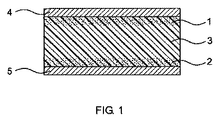
本発明の電極の更なる実施態様では、電極は、電気伝導性カーボン粒子を含む第1表面層および第2表面層を有し、前記第1表面層および第2表面層は、互いに反対側に配置され、エラストマー層により互いに分離される。製造方法に起因して、第1表面層および第2表面層は、分離電気絶縁エラストマーに一体的に接合する。弾性コンデンサーは、誘電体により分離された2つの電気伝導性層の上記構造により実現される。次いで、上記の付加的な電気伝導性層は、第1表面層および/または第2表面層上に直接配置する。 In a further embodiment of the electrode of the present invention, the electrode has a first surface layer and a second surface layer containing electrically conductive carbon particles, the first surface layer and the second surface layer being opposite to each other. Placed and separated from each other by an elastomeric layer. Due to the manufacturing method, the first surface layer and the second surface layer are integrally joined to the separated electrically insulating elastomer. An elastic capacitor is realized by the above structure of two electrically conductive layers separated by a dielectric. The additional electrically conductive layer is then placed directly on the first surface layer and / or the second surface layer.
本発明の電極の更なる実施態様では、これは、電気伝導性カーボン粒子を含む表面層に配置された付加的な電気伝導性層を含み、該付加的な電気伝導性層は、断裂する前の表面層の伸びにより破壊または断裂する。 In a further embodiment of the electrode according to the invention, this comprises an additional electrically conductive layer arranged on a surface layer comprising electrically conductive carbon particles, the additional electrically conductive layer before being ruptured. It breaks or tears due to the elongation of the surface layer.
付加的な電気層は、例えば導電性表面被覆物、導電性ペースト、金属層または電気伝導性ポリマーの層であってよい。金属の例は、貴金属、銅および/または錫である。付加的な電気層は、≧10nm〜≦50μmまたは≧20nm〜≦10μmの厚みを有することができる。付加的な電気伝導性層の物質は、該付加的な層がまず、表面層の伸びにより破壊または断裂するように選択される。ここで、系全体の電気伝導性が、破壊または断裂した被覆物とカーボン粒子を含む表面層との接触により急に破壊されないが、その代わり特定の程度に維持されることが有利である。言い換えれば、伸張性電極の電力密度は、応力の結果、時間で減少するが、これは完全には終わらない。この挙動は、エラストマーが繰り返される伸びおよび脱応力に曝され、電気伝導性が、時間全体にわたって要求される場合に特に有利である。 The additional electrical layer can be, for example, a conductive surface coating, a conductive paste, a metal layer or a layer of an electrically conductive polymer. Examples of metals are noble metals, copper and / or tin. The additional electrical layer can have a thickness of ≧ 10 nm to ≦ 50 μm or ≧ 20 nm to ≦ 10 μm. The material of the additional electrically conductive layer is selected such that the additional layer first breaks or ruptures due to the elongation of the surface layer. Here, it is advantageous that the electrical conductivity of the entire system is not suddenly destroyed by contact between the destroyed or torn coating and the surface layer containing the carbon particles, but instead is maintained to a certain degree. In other words, the power density of the extensible electrode decreases with time as a result of stress, but this does not end completely. This behavior is particularly advantageous when the elastomer is exposed to repeated elongation and stress and electrical conductivity is required over time.
付加的な電気電送性層は、好ましくは金、銀、銅、インジウム−錫酸化物、フッ素ドープト酸化錫(IV)、アルミニウムドープト酸化亜鉛、アンチモンドープト酸化錫(IV)および/またはポリ(3,4−エチレンジオキシチオフェン)を含む。金は、例えばスパッタリングにより適用することができる。ポリ(3,4−エチレンジオキシチオフェン)は、通常PEDOTまたはPEDTと称され、ポリマーの調製物から適用することができる。 The additional electroconductive layer is preferably gold, silver, copper, indium-tin oxide, fluorine-doped tin oxide (IV), aluminum-doped zinc oxide, antimony-doped tin oxide (IV) and / or poly ( 3,4-ethylenedioxythiophene). Gold can be applied, for example, by sputtering. Poly (3,4-ethylenedioxythiophene) is commonly referred to as PEDOT or PEDT and can be applied from a polymer preparation.
本発明によるエラストマー物体は、電気伝導性カーボン粒子を含むエラストマー表面層を有する担体材料の複合材料の形態であることが可能である。担体材料の例は、セラミック、金属、およびポリマー、例えばポリカーボネートまたはポリオレフィン等である。従って、例えば成形金属部を、まずエラストマーで被覆し、次いでエラストマー表面層に、カーボン粒子および付加的な電気伝導性層を付与することができる。 The elastomeric object according to the present invention can be in the form of a composite of carrier material having an elastomeric surface layer comprising electrically conductive carbon particles. Examples of support materials are ceramics, metals, and polymers such as polycarbonate or polyolefin. Thus, for example, the shaped metal part can be first coated with an elastomer and then carbon particles and an additional electrically conductive layer can be applied to the elastomer surface layer.
さらに、本発明は、本発明による電極の、電気機械変換器としての、電気機械作動装置としてのおよび/または電気機械センサーとしての使用を提供する。この場合、電極におけるエラストマーは、電気活性ポリマー、特に誘電エラストマーである。 Furthermore, the present invention provides the use of the electrode according to the invention as an electromechanical transducer, as an electromechanical actuator and / or as an electromechanical sensor. In this case, the elastomer in the electrode is an electroactive polymer, in particular a dielectric elastomer.
本発明を、図と併せて以下の例により説明する。図では:
図1は、多層構造を有する電極配置を示し、
図2、3および4は、伸張中の伝導性測定を種々の試料について示し、
図5a、5b、6a、6b、7aおよび7bは、種々のエラストマー試料の走査型電子顕微鏡写真を示す。
The invention is illustrated by the following examples in conjunction with the figures. In the figure:
FIG. 1 shows an electrode arrangement with a multilayer structure,
2, 3 and 4 show conductivity measurements during stretching for various samples,
Figures 5a, 5b, 6a, 6b, 7a and 7b show scanning electron micrographs of various elastomer samples.
図1は、多層構造を有する本発明による電極配置を示す。エラストマー作業片から出発して、カーボンナノチューブのようなカーボン粒子は、エラストマーの上部表面層(1)および下部表面層(2)中へ導入した。これらの粒子は、短い線または点により個々の層(1、2)に示される。粒子が表面層中への制限浸透深度を有することが分かる。付加的な電気伝導性層(4、5)は、表面層(1、2)のそれぞれに存在する。表面層(1、2)は、粒子不含エラストマー層(3)により互いに分離する。製造方法に起因して、電極は常に、表面層(1、2)についてワンピース構造を有し、表面層は、粒子不含層(3)へ一体的に接合される。示される電極は、適当な寸法の場合、例えばフィルム状コンデンサーとしてまたは電気活性ポリマー(EAP)として働くことができる。 FIG. 1 shows an electrode arrangement according to the invention having a multilayer structure. Starting from the elastomeric work piece, carbon particles such as carbon nanotubes were introduced into the upper surface layer (1) and the lower surface layer (2) of the elastomer. These particles are indicated in the individual layers (1, 2) by short lines or dots. It can be seen that the particles have a limited depth of penetration into the surface layer. An additional electrically conductive layer (4, 5) is present in each of the surface layers (1, 2). The surface layers (1, 2) are separated from each other by the particle-free elastomer layer (3). Due to the manufacturing method, the electrode always has a one-piece structure for the surface layers (1, 2), which are integrally joined to the particle-free layer (3). The electrode shown can serve as a film capacitor or as an electroactive polymer (EAP), for example, in suitable dimensions.
実施例は、2つのエラストマーE1およびE2の官能基化に関する。エラストマーE1は、ISO 868に従う80のショアA硬度および−35℃のガラス転移温度Tgを有する熱可塑性ポリウレタン(DESMOPAN登録商標 3380A、Bayer MaterialScience AGから)であった。エラストマーE2は、PO系ポリエーテルポリオール(Acclaim(登録商標) 6300、Bayer MaterialScience AGから)のジフェニルメタン4,4’−ジイソシアネート(Desmodur(登録商標) 44 M Flakes、Bayer MaterialScience AGから)による予備伸張により得られたプレポリマーから調製されたポリウレタンであり、これは、ポリテトラメチレンエーテルグリコール(M=2000g/モル)により最後に架橋した。エラストマーE2のガラス転移温度Tgは、−65℃であった。
The examples relate to the functionalization of two elastomers E1 and E2. Elastomers E1 were thermoplastic polyurethane with 80 Shore A hardness and -35 ° C. The glass transition temperature T g of the the according to ISO 868 (DESMOPAN ® 3380A, from Bayer MaterialScience AG). Elastomer E2 is a PO-based polyether polyol (Acclaim (TM) 6300, from Bayer MaterialScience AG),
実施例に記載のカーボン粒子は、1つの場合には、Bayer MaterialScience AGからの商品名BAYTUBES(登録商標) C 150 Pを有する多壁カーボンナノチューブの形態でのカーボンナノチューブ(CNT)であった。カーボン粒子の他の種類は、導電性カーボンブラックの形態でのカーボンブラック(Ketjenblack 600)であった。 The carbon particles described in the examples were in one case carbon nanotubes (CNTs) in the form of multi-walled carbon nanotubes with the trade name BAYTUBES® C 150 P from Bayer MaterialScience AG. Another type of carbon particles was carbon black (Ketjenblack 600) in the form of conductive carbon black.
被覆剤として用いるPEDOTは、HCStarckからの商品名Clevios P(登録商標)を有するポリ−3,4−エチレンジオキシチオフェンであった。これは、脱イオン水中に0.3重量%含有する調製物の形態であった。 The PEDOT used as a coating was poly-3,4-ethylenedioxythiophene with the trade name Clevios P® from HCStarck. This was in the form of a preparation containing 0.3% by weight in deionized water.
浸漬溶液は、超音波プローブによる溶媒中での所定量のカーボン粒子の超音波処理により製造し、直ぐに用いた。ここで、超音波の周波数は、20kHzであり、電力密度は、300W/kgであった。 The immersion solution was produced by ultrasonic treatment of a predetermined amount of carbon particles in a solvent using an ultrasonic probe, and used immediately. Here, the frequency of the ultrasonic wave was 20 kHz, and the power density was 300 W / kg.
エラストマー表面を官能基化するために、試料を、浸漬調製物中に完全に浸し、超音波槽中で所定の時間、超音波で処理する。試料を、該槽から取り出した後、表面を、アセトンで簡単に洗い流し、室温において完全に乾燥させ、次いで水性石鹸溶液でこすった。 In order to functionalize the elastomeric surface, the sample is completely immersed in the immersion preparation and treated ultrasonically for a predetermined time in an ultrasonic bath. After the sample was removed from the bath, the surface was briefly rinsed with acetone, allowed to dry completely at room temperature, and then rubbed with an aqueous soap solution.
こうしてCNT官能基化されたエラストマーの任意の被覆を、第2段階において金の蒸着(CressingtonからのSputter Coater 108auto)または上記PEDOT含有溶液中への20秒間浸漬することにより行った。適用された金層は、不透明であり、金属光沢を有した。従って、10nmを越える層厚みが想定された。 An optional coating of the CNT functionalized elastomer was thus carried out in the second stage by vapor deposition of gold (Sputter Coater 108auto from Cresston) or immersion for 20 seconds in the PEDOT containing solution. The applied gold layer was opaque and had a metallic luster. Therefore, a layer thickness exceeding 10 nm was assumed.
表面および体積抵抗は、こうして処理したエラストマーについて標準ASTM D 257に従って計測した。さらに、表面抵抗は、機械伸張に応じて測定した。試料を横切る抵抗は、Keithleyからの従来使用されるマルチメーター、型2400により、低速運転引張試験の間、歪み速度1mm/分、連続的に測定し、第2工程において、力−変形曲線を、個々の測定のタイムスタンプにより抵抗測定と同期化した。 Surface and volume resistance were measured according to standard ASTM D 257 for the elastomer thus treated. Furthermore, the surface resistance was measured according to mechanical stretching. The resistance across the sample was measured continuously with a conventionally used multimeter from Keithley, mold 2400, at a strain rate of 1 mm / min during the low speed tensile test, and in the second step, the force-deformation curve was Synchronized with resistance measurement by time stamp of individual measurement.
実験条件および得られた結果を以下の表に示す。 The experimental conditions and the results obtained are shown in the table below.

これらの実験の結果を、図2、3および4に示す。 The results of these experiments are shown in FIGS.
図2は、エラストマーE1eの種々の変形に対する伸びE(X軸)についての力F(左手軸)または試料の引張棒の抵抗R(右手軸)の依存を示す。 FIG. 2 shows the dependence of the force F (left hand axis) on the elongation E (X axis) or the resistance R (right hand axis) of the sample tension bar for various deformations of the elastomer E1e.
測定曲線100および110は、変形中の力に関する。曲線100は、実質的には同一である2つの曲線の重ね合わせである。これらの曲線の1つは、更なる被覆物を有さないエラストマー試料E1eに関し、他方は、金層を有するエラストマー試料E1eに関する。金被覆試料E1eについての計測は、約275%の伸びにおいて停止し、この伸びを越えた曲線100の減少した厚みから分かる。この曲線の形状は、更なる金層が、エラストマーの機械特性について影響を有さないことを示す。測定曲線110は、付加的なPEDOT層を有するエラストマーE1eの試料に関する。
Measurement curves 100 and 110 relate to forces during deformation.
曲線120、130および140は、変形Dに応じた抵抗Rを、エラストマーE1eの種々の試料について示す。曲線120は、金被覆試料に関する。ここでも、測定は、約275%の伸びにおいて停止した。曲線130は、更なる被覆物を有するエラストマーE1eに関する。最後に、曲線140は、エラストマーE1eのPEDOT被覆試料に関する。エラストマーE1eは、変形下で消失せず、および付加的な導電性表面層により特定の変形範囲で更に著しく向上させることができる伝導性を有することが明らかに分かる。
図3は、エラストマーE1eについての力F(左手y軸)の依存を測定曲線210において再び示す。概算では、抵抗が、約230%の測定伸び範囲で約10の2乗増加することを示す。
FIG. 3 again shows the dependence of force F (left-handed y-axis) on elastomer E1e in
図4は、アセトンに浸漬しなかったエラストマーE1のカーボン粒子で官能基化されなかった未処理試料に関する(E1aとして示された試料についての場合である)。図は、金で両側にスパッタされたエラストマーE1の試料に対する伸びE(x軸)について、測定曲線310において力F(左手y軸)または測定曲線300において抵抗R(右手y軸)の依存を示す。CNT層をエラストマー中へ導入しない場合、金スパッタ試料の伝導性は、少しの変形でさえ変形により破壊される。
FIG. 4 relates to an untreated sample that was not functionalized with carbon particles of elastomer E1 that was not immersed in acetone (this is the case for the sample designated as E1a). The figure shows the dependence of the force F (left-hand y-axis) on the
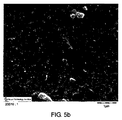
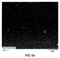
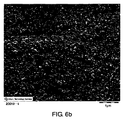
図5a、5b、6a、6bおよび7aおよび7bは、本発明による種々の試料の走査型電子顕微鏡(SEM)を示す。これらは、FEIからのSEM型ESEM Quanta 400により作製した。
Figures 5a, 5b, 6a, 6b and 7a and 7b show scanning electron microscopes (SEM) of various samples according to the present invention. These were produced by SEM
図5aは、エラストマーE2bの試料の表面の走査型電子顕微鏡写真を示す。この試料の拡大顕微鏡写真を図5bに示す。図6aは、エラストマーE2cの試料の表面の走査型電子顕微鏡写真を示し、図6bは、この試料の拡大顕微鏡写真を示す。対応して、図7aは、エラストマーE2dの試料の表面の走査型電子顕微鏡写真を示し、図7bは、この試料の拡大顕微鏡写真を示す。 FIG. 5a shows a scanning electron micrograph of the surface of a sample of elastomer E2b. An enlarged micrograph of this sample is shown in FIG. FIG. 6a shows a scanning electron micrograph of the surface of a sample of elastomer E2c, and FIG. 6b shows an enlarged micrograph of this sample. Correspondingly, FIG. 7a shows a scanning electron micrograph of the surface of a sample of elastomer E2d, and FIG. 7b shows an enlarged micrograph of this sample.
走査型電子顕微鏡写真において、粒子、すなわちカーボンナノチューブおよび/またはカーボンブラック粒子が、ポリマーマトリックス中に組み込まれ、その中に封入されていることが分かる。表面は、大きくとも、粒子により生じた浮き彫り構造を示す。緩いナノチューブ端だけがポリマーマトリックスから突出することがある。従って、全体的に、粒子がポリマー表面中へ強く組み込まれた。 In the scanning electron micrograph it can be seen that the particles, ie carbon nanotubes and / or carbon black particles, are incorporated into and encapsulated in the polymer matrix. The surface, at most, shows the relief structure caused by the particles. Only the loose nanotube ends may protrude from the polymer matrix. Overall, therefore, the particles were strongly incorporated into the polymer surface.
Claims (15)
(A)≧−130℃〜≦0℃のガラス転移温度Tgを有し、応力σが伸びの増加を伴って減少しないエラストマーの供給、
(B)前記エラストマーの表面層の膨潤を引き起こすことができる溶媒中における≧0.3nm〜≦3000nmの平均粒径を有する非凝集化カーボン粒子の調製物の供給、
(C)前記エラストマーの表面層とカーボン粒子の調製物とを接触させる工程、
(D)前記カーボン粒子の調製物を、エラストマーの表面層上へ、エラストマーが溶液中へ入り込むのに不十分な時間、作用させる工程、および
(E)前記カーボン粒子の調製物のエラストマーの表面層上への作用を終了する工程
を含む方法。 A method for producing an extensible electrode having a surface layer containing electrically conductive carbon particles, the following steps:
(A) ≧ -130 have ° C. ~ ≦ 0 ° C. The glass transition temperature T g of the supply of the elastomer stress σ does not decrease with increasing elongation,
(B) supply of a preparation of non-agglomerated carbon particles having an average particle size of ≧ 0.3 nm to ≦ 3000 nm in a solvent capable of causing swelling of the surface layer of the elastomer;
(C) contacting the surface layer of the elastomer with a preparation of carbon particles;
(D) allowing the carbon particle preparation to act on the elastomeric surface layer for a time that is insufficient for the elastomer to enter the solution; and (E) the elastomeric surface layer of the carbon particle preparation. A method comprising the step of terminating the action on the top.
(F)付加的な電気伝導性層を、工程(B)〜(E)において得られる電気伝導性カーボン粒子を含む表面層へ適用し、得られる付加的な電気伝導性層は、断裂する前に表面層の伸びにより破壊または断裂する、工程
を更に含む、請求項1に記載の方法。 The following steps:
(F) An additional electrically conductive layer is applied to the surface layer containing the electrically conductive carbon particles obtained in the steps (B) to (E), and the obtained additional electrically conductive layer is not ruptured. The method according to claim 1, further comprising a step of breaking or tearing due to elongation of the surface layer.
Applications Claiming Priority (3)
| Application Number | Priority Date | Filing Date | Title |
|---|---|---|---|
| EP20090009472 EP2284933A1 (en) | 2009-07-22 | 2009-07-22 | Method for producing extendable electrodes |
| EP09009472.3 | 2009-07-22 | ||
| PCT/EP2010/004283 WO2011009549A1 (en) | 2009-07-22 | 2010-07-14 | Method for the production of stretchable electrodes |
Publications (1)
| Publication Number | Publication Date |
|---|---|
| JP2012533857A true JP2012533857A (en) | 2012-12-27 |
Family
ID=41220395
Family Applications (1)
| Application Number | Title | Priority Date | Filing Date |
|---|---|---|---|
| JP2012520929A Pending JP2012533857A (en) | 2009-07-22 | 2010-07-14 | Method for manufacturing extensible electrode |
Country Status (12)
| Country | Link |
|---|---|
| US (1) | US20120177934A1 (en) |
| EP (2) | EP2284933A1 (en) |
| JP (1) | JP2012533857A (en) |
| KR (1) | KR20120047261A (en) |
| CN (1) | CN102498595A (en) |
| AU (1) | AU2010275788A1 (en) |
| CA (1) | CA2768677A1 (en) |
| IN (1) | IN2012DN00600A (en) |
| RU (1) | RU2012106077A (en) |
| SG (1) | SG177487A1 (en) |
| TW (1) | TW201126795A (en) |
| WO (1) | WO2011009549A1 (en) |
Cited By (4)
| Publication number | Priority date | Publication date | Assignee | Title |
|---|---|---|---|---|
| JP2014081355A (en) * | 2012-09-28 | 2014-05-08 | Bando Chem Ind Ltd | Electrostatic capacitance type sensor sheet and electrostatic capacitance type sensor sheet manufacturing method |
| WO2015119217A1 (en) * | 2014-02-05 | 2015-08-13 | 独立行政法人科学技術振興機構 | Stretchable conductor, method for manufacturing same, and paste for forming stretchable conductor |
| JPWO2015079951A1 (en) * | 2013-11-28 | 2017-03-16 | バンドー化学株式会社 | Stretchable electrode, sensor sheet, and capacitive sensor |
| JP7301960B2 (en) | 2018-10-11 | 2023-07-03 | サステナブル エナジー エフィシェント デザインド ストラクチャーズ リミテッド | New carbon nanostructures for energy generation applications |
Families Citing this family (65)
| Publication number | Priority date | Publication date | Assignee | Title |
|---|---|---|---|---|
| WO2015006030A1 (en) * | 2013-07-06 | 2015-01-15 | Frank David L | Dense energy ultra-capacitor preform, thin film, module and fabrication methods therefor |
| US8608984B1 (en) | 2010-02-23 | 2013-12-17 | Cleveland Medical Polymers, Inc. | Polymer nano-composites as dry sensor material for biosignal sensing |
| US9324508B2 (en) * | 2011-06-15 | 2016-04-26 | Nokia Technologies Oy | Substrate for electrode capable of undergoing reversible deformation |
| CH705539A1 (en) * | 2011-09-06 | 2013-03-15 | Empa | A dielectric actuator. |
| US8871385B2 (en) * | 2012-01-27 | 2014-10-28 | Battelle Energy Alliance, Llc | Electrodes including a polyphosphazene cyclomatrix, methods of forming the electrodes, and related electrochemical cells |
| DE102012212222B4 (en) * | 2012-03-12 | 2018-05-30 | Fraunhofer-Gesellschaft zur Förderung der angewandten Forschung e.V. | Fluorosilicone-based dielectric elastomer and process for its preparation |
| US10147558B2 (en) * | 2012-04-18 | 2018-12-04 | Arizona Board Of Regents On Behalf Of Northern Arizona University | Structural supercapacitor |
| KR101903053B1 (en) * | 2012-07-10 | 2018-11-23 | 삼성디스플레이 주식회사 | Flexible display device |
| CN103545556B (en) * | 2012-07-13 | 2016-01-20 | 清华大学 | The preparation method of film lithium ion battery |
| CN103545554B (en) * | 2012-07-13 | 2016-06-08 | 清华大学 | The preparation method of lithium ion battery |
| WO2014042152A1 (en) * | 2012-09-14 | 2014-03-20 | シャープ株式会社 | Display panel, display apparatus, and manufacturing method |
| WO2014109799A1 (en) | 2012-09-17 | 2014-07-17 | President And Fellows Of Harvard College | Soft exosuit for assistance with human motion |
| US9212960B2 (en) | 2012-10-22 | 2015-12-15 | The Board Of Trustees Of The Leland Stanford Junior University | Nanostructures with strain-induced resistance |
| TWI524825B (en) | 2012-10-29 | 2016-03-01 | 財團法人工業技術研究院 | Method of transferring carbon conductive film |
| DE102012112153B4 (en) | 2012-12-12 | 2018-05-09 | Rembert Born | Process for producing a textile-based electrode and textile-based electrode |
| CN103194142B (en) * | 2013-04-28 | 2015-12-09 | 吉林大学 | Antistatic high-temperaure coating of a kind of polyether-ether-ketone and preparation method thereof |
| WO2014194257A1 (en) | 2013-05-31 | 2014-12-04 | President And Fellows Of Harvard College | Soft exosuit for assistance with human motion |
| WO2015088863A2 (en) | 2013-12-09 | 2015-06-18 | President And Fellows Of Harvard College | Assistive flexible suits, flexible suit systems, and methods for making and control thereof to assist human mobility |
| DE102013225702A1 (en) | 2013-12-12 | 2015-06-18 | Rembert Born | Textile-based electrode, process for its preparation and use |
| WO2015095379A1 (en) | 2013-12-17 | 2015-06-25 | The Board Of Trustees Of The Leland Stanford Junior University | Surface area-based pressure sensing |
| WO2015120186A1 (en) | 2014-02-05 | 2015-08-13 | President And Fellows Of Harvard College | Systems, methods, and devices for assisting walking for developmentally-delayed toddlers |
| EP3128963A4 (en) | 2014-04-10 | 2017-12-06 | President and Fellows of Harvard College | Orthopedic device including protruding members |
| DE102014005851B4 (en) * | 2014-04-22 | 2018-10-18 | Festo Ag & Co. Kg | Method and device for producing elastomer actuators |
| US10722174B2 (en) | 2014-07-11 | 2020-07-28 | The Board Of Trustees Of The Leland Stanford Junior University | Skin-conformal sensors |
| US9625330B2 (en) | 2014-08-01 | 2017-04-18 | The Board Of Trustees Of The Leland Stanford Junior University | Methods and apparatus concerning multi-tactile sensitive (E-skin) pressure sensors |
| EP3194769B1 (en) | 2014-09-19 | 2020-04-08 | President and Fellows of Harvard College | Soft exosuit for assistance with human motion |
| US10072177B2 (en) | 2014-11-06 | 2018-09-11 | E I Du Pont De Nemours And Company | Stretchable polymer thick film compositions for thermoplastic substrates and wearables electronics |
| CN106767943B (en) * | 2014-12-09 | 2019-04-26 | 金冬梅 | Incude cilium, sensor, artificial intelligence robot |
| CN105369475B (en) * | 2015-08-27 | 2017-10-20 | 新疆大学 | Tin antimony and carbon nano-fiber active material and preparation method thereof |
| ITUB20153380A1 (en) * | 2015-09-03 | 2017-03-03 | Windtex Vagotex Spa | PROCEDURE FOR THE REALIZATION OF A MULTI-LAYER POLYURETHANE MEMBRANE BASED ON GRAPHENE. |
| US10217810B2 (en) * | 2015-12-07 | 2019-02-26 | Microchip Technology Incorporated | Capacitor formed on heavily doped substrate |
| CN105428082B (en) * | 2015-12-27 | 2018-02-27 | 复旦大学 | Stretchable ultracapacitor based on nitrogen-doped carbon nanometer pipe array/polyurethane combination electrode and preparation method thereof |
| DE102016203240A1 (en) * | 2016-02-29 | 2017-08-31 | Robert Bosch Gmbh | Process for producing an electrode, electrode and battery cell |
| CN109069278A (en) | 2016-03-13 | 2018-12-21 | 哈佛大学校长及研究员协会 | Flexible member for being anchored on body |
| US11171324B2 (en) | 2016-03-15 | 2021-11-09 | Honda Motor Co., Ltd. | System and method of producing a composite product |
| US11383213B2 (en) | 2016-03-15 | 2022-07-12 | Honda Motor Co., Ltd. | System and method of producing a composite product |
| CN105838310B (en) * | 2016-05-17 | 2019-01-18 | 西安工程大学 | A kind of preparation method of UV photocuring onion carbon/wicker copper conducting resinl |
| US11498203B2 (en) | 2016-07-22 | 2022-11-15 | President And Fellows Of Harvard College | Controls optimization for wearable systems |
| CN106711453A (en) * | 2016-12-28 | 2017-05-24 | 深圳市德方纳米科技股份有限公司 | Conductive carbon slurry, cathode material pole piece and lithium ion battery |
| US11014804B2 (en) | 2017-03-14 | 2021-05-25 | President And Fellows Of Harvard College | Systems and methods for fabricating 3D soft microstructures |
| US11081684B2 (en) | 2017-05-24 | 2021-08-03 | Honda Motor Co., Ltd. | Production of carbon nanotube modified battery electrode powders via single step dispersion |
| US10658651B2 (en) | 2017-07-31 | 2020-05-19 | Honda Motor Co., Ltd. | Self standing electrodes and methods for making thereof |
| US20190036102A1 (en) | 2017-07-31 | 2019-01-31 | Honda Motor Co., Ltd. | Continuous production of binder and collector-less self-standing electrodes for li-ion batteries by using carbon nanotubes as an additive |
| CN107564729A (en) * | 2017-08-02 | 2018-01-09 | 苏州柔能纳米科技有限公司 | The preparation method of flexible nano netty compound material |
| US11201318B2 (en) | 2017-09-15 | 2021-12-14 | Honda Motor Co., Ltd. | Method for battery tab attachment to a self-standing electrode |
| US11121358B2 (en) | 2017-09-15 | 2021-09-14 | Honda Motor Co., Ltd. | Method for embedding a battery tab attachment in a self-standing electrode without current collector or binder |
| EP3695423B1 (en) * | 2017-10-11 | 2021-11-24 | Single Buoy Moorings Inc. | Electro-active polymer device and method for manufacturing such a device |
| EP3741295A4 (en) | 2018-01-15 | 2021-09-15 | NOK Corporation | Bioelectrode |
| CN111372514B (en) | 2018-01-15 | 2023-06-02 | Nok株式会社 | Bioelectrode |
| DE102018221051A1 (en) * | 2018-04-05 | 2019-10-10 | Continental Reifen Deutschland Gmbh | Apparatus for measuring a mechanical force comprising first, second, third, fourth and fifth layers and the uses of the apparatus and tires or engineering rubber articles comprising the apparatus |
| CN110660592B (en) * | 2018-06-29 | 2020-12-04 | 清华大学 | Method for preparing stretchable capacitor electrode-conductor structure |
| DE102018218637B3 (en) * | 2018-10-31 | 2020-02-20 | Festo Ag & Co. Kg | Electroactive polymer actuator device |
| US11535517B2 (en) | 2019-01-24 | 2022-12-27 | Honda Motor Co., Ltd. | Method of making self-standing electrodes supported by carbon nanostructured filaments |
| WO2021016319A1 (en) * | 2019-07-22 | 2021-01-28 | Honda Motor Co., Ltd. | Stretchable and flexible lithium ion battery |
| US11325833B2 (en) | 2019-03-04 | 2022-05-10 | Honda Motor Co., Ltd. | Composite yarn and method of making a carbon nanotube composite yarn |
| US11352258B2 (en) | 2019-03-04 | 2022-06-07 | Honda Motor Co., Ltd. | Multifunctional conductive wire and method of making |
| CN114008911A (en) * | 2019-06-24 | 2022-02-01 | 千叶正毅 | Dielectric elastomer transducer |
| US11539042B2 (en) | 2019-07-19 | 2022-12-27 | Honda Motor Co., Ltd. | Flexible packaging with embedded electrode and method of making |
| US11787105B2 (en) * | 2019-11-14 | 2023-10-17 | Rolls-Royce Corporation | Fused filament fabrication of components including predetermined yield points based on composition functions |
| CN111117227A (en) * | 2019-12-31 | 2020-05-08 | 湖南华曙高科技有限责任公司 | Preparation method of polymer powder material for optical fiber laser sintering |
| CN111477838B (en) * | 2020-04-08 | 2021-05-18 | 北京科技大学 | Integrated stretchable lithium ion battery and preparation method thereof |
| TWI732585B (en) * | 2020-06-05 | 2021-07-01 | 三芳化學工業股份有限公司 | Conductive film and manufacturing method thereof |
| CN112080031B (en) * | 2020-08-13 | 2022-05-20 | 哈尔滨工业大学 | Preparation method of stretchable conductive polymer film with self-repairing function for flexible nerve electrode |
| CN112993223B (en) * | 2021-02-07 | 2022-04-12 | 西南科技大学 | Lithium ion battery cathode material with double-layer coating structure and preparation method thereof |
| CN114188070B (en) * | 2021-12-08 | 2024-03-19 | 成都科威尔博新材料科技有限公司 | Wearable electrode patch and preparation method thereof |
Family Cites Families (11)
| Publication number | Priority date | Publication date | Assignee | Title |
|---|---|---|---|---|
| US4265727A (en) * | 1979-10-22 | 1981-05-05 | Hitco | Composite electrodes |
| US6376971B1 (en) * | 1997-02-07 | 2002-04-23 | Sri International | Electroactive polymer electrodes |
| US6084047A (en) * | 1997-11-06 | 2000-07-04 | Eastman Chemical Company | Elastomeric amorphous olefin terpolymer |
| US7119028B1 (en) * | 2003-10-29 | 2006-10-10 | The United States Of America As Represented By The Secretary Of The Navy | Surface imprinted films with carbon nanotubes |
| CN101090586B (en) * | 2006-06-16 | 2010-05-12 | 清华大学 | Nano flexible electrothermal material and heating device containing the nano flexible electrothermal material |
| US9493635B2 (en) * | 2006-07-31 | 2016-11-15 | The United States Of America As Represented By The Administrator Of The National Aeronautics And Space Administration | Nanocomposites from stable dispersions of carbon nanotubes in polymeric matrices using dispersion interaction |
| US20110001398A1 (en) * | 2006-11-08 | 2011-01-06 | Usa As Represented By The Administrator Of The National Aeronautics And Space Administration | Carbon Nanotube Film Electrode and an Electroactive Device Fabricated with the Carbon Nanotube Film Electrode and a Method for Making Same |
| EP2097928A4 (en) * | 2006-12-26 | 2013-07-24 | Texas Southern University | Instantaneous electrodeposition of metal nanostructures on carbon nanotubes |
| WO2008150867A2 (en) | 2007-05-29 | 2008-12-11 | Innova Materials, Llc | Surfaces having particles and related methods |
| US20080318026A1 (en) * | 2007-06-25 | 2008-12-25 | University Of Dayton | Method of modifying carbon nanomaterials, composites incorporating modified carbon nanomaterials and method of producing the composites |
| DE102007044031A1 (en) | 2007-09-14 | 2009-03-19 | Bayer Materialscience Ag | Carbon nanotube powder, carbon nanotubes and methods of making same |
-
2009
- 2009-07-22 EP EP20090009472 patent/EP2284933A1/en not_active Withdrawn
-
2010
- 2010-01-14 US US13/384,300 patent/US20120177934A1/en not_active Abandoned
- 2010-07-14 JP JP2012520929A patent/JP2012533857A/en active Pending
- 2010-07-14 CN CN2010800334820A patent/CN102498595A/en active Pending
- 2010-07-14 AU AU2010275788A patent/AU2010275788A1/en not_active Abandoned
- 2010-07-14 KR KR20127004194A patent/KR20120047261A/en not_active Application Discontinuation
- 2010-07-14 WO PCT/EP2010/004283 patent/WO2011009549A1/en active Application Filing
- 2010-07-14 CA CA2768677A patent/CA2768677A1/en not_active Abandoned
- 2010-07-14 IN IN600DEN2012 patent/IN2012DN00600A/en unknown
- 2010-07-14 RU RU2012106077/07A patent/RU2012106077A/en not_active Application Discontinuation
- 2010-07-14 SG SG2012000261A patent/SG177487A1/en unknown
- 2010-07-14 EP EP10735201A patent/EP2457277A1/en not_active Withdrawn
- 2010-07-21 TW TW99123898A patent/TW201126795A/en unknown
Cited By (8)
| Publication number | Priority date | Publication date | Assignee | Title |
|---|---|---|---|---|
| JP2014081355A (en) * | 2012-09-28 | 2014-05-08 | Bando Chem Ind Ltd | Electrostatic capacitance type sensor sheet and electrostatic capacitance type sensor sheet manufacturing method |
| JPWO2015079951A1 (en) * | 2013-11-28 | 2017-03-16 | バンドー化学株式会社 | Stretchable electrode, sensor sheet, and capacitive sensor |
| US10184779B2 (en) | 2013-11-28 | 2019-01-22 | Bando Chemical Industries, Ltd. | Stretchable electrode, sensor sheet and capacitive sensor |
| JP2019091717A (en) * | 2013-11-28 | 2019-06-13 | バンドー化学株式会社 | Stretchable electrode, sensor sheet and capacitive sensor |
| WO2015119217A1 (en) * | 2014-02-05 | 2015-08-13 | 独立行政法人科学技術振興機構 | Stretchable conductor, method for manufacturing same, and paste for forming stretchable conductor |
| JPWO2015119217A1 (en) * | 2014-02-05 | 2017-03-30 | 国立研究開発法人科学技術振興機構 | Stretchable conductor, production method thereof, and paste for stretchable conductor formation |
| US10176903B2 (en) | 2014-02-05 | 2019-01-08 | Japan Science And Technology Agency | Stretchable conductor, method for manufacturing same, and paste for forming stretchable conductor |
| JP7301960B2 (en) | 2018-10-11 | 2023-07-03 | サステナブル エナジー エフィシェント デザインド ストラクチャーズ リミテッド | New carbon nanostructures for energy generation applications |
Also Published As
| Publication number | Publication date |
|---|---|
| TW201126795A (en) | 2011-08-01 |
| CN102498595A (en) | 2012-06-13 |
| US20120177934A1 (en) | 2012-07-12 |
| CA2768677A1 (en) | 2011-01-27 |
| KR20120047261A (en) | 2012-05-11 |
| IN2012DN00600A (en) | 2015-06-12 |
| RU2012106077A (en) | 2013-08-27 |
| WO2011009549A1 (en) | 2011-01-27 |
| EP2457277A1 (en) | 2012-05-30 |
| SG177487A1 (en) | 2012-02-28 |
| AU2010275788A1 (en) | 2012-02-09 |
| EP2284933A1 (en) | 2011-02-16 |
Similar Documents
| Publication | Publication Date | Title |
|---|---|---|
| JP2012533857A (en) | Method for manufacturing extensible electrode | |
| McCoul et al. | Recent advances in stretchable and transparent electronic materials | |
| Kwon et al. | Robust and flexible aramid nanofiber/graphene layer-by-layer electrodes | |
| Sim et al. | Self-healing graphene oxide-based composite for electromagnetic interference shielding | |
| Galantini et al. | Functionalized carbon nanotubes as a filler for dielectric elastomer composites with improved actuation performance | |
| Yang et al. | Modified carbon nanotube composites with high dielectric constant, low dielectric loss and large energy density | |
| US20110281071A1 (en) | Process for incorporating carbon particles into a polyurethane surface layer | |
| EP2557207B1 (en) | Stretchable conductive nanofibers, stretchable electrode using the same and method of producing the stretchable conductive nanofibers | |
| Tang et al. | Graphene/polymer composite materials: processing, properties and applications | |
| Yi et al. | CNT-assisted design of stable liquid metal droplets for flexible multifunctional composites | |
| Tian et al. | Engineering the volumetric effect of Polypyrrole for auto-deformable supercapacitor | |
| JP2011504280A (en) | Transparent conductive film with improved conductivity and method for producing the same | |
| Yu et al. | Binding conductive ink initiatively and strongly: transparent and thermally stable cellulose nanopaper as a promising substrate for flexible electronics | |
| Hu et al. | Fabrication of stretchable multi-element composite for flexible solid-state electrochemical capacitor application | |
| US20150294800A1 (en) | Free-standing hybrid nanomembrane as energy storage electrode and the fabrication method thereof | |
| Rasouli et al. | The effect of MWCNT content on electropolymerization of PPy film and electromechanical behavior of PPy electrode-based soft actuators | |
| Park et al. | Interfacial durability and electrical properties of CNT or ITO/PVDF nanocomposites for self-sensor and micro actuator applications | |
| Azoubel et al. | Controlling Adhesion Properties of SWCNT–PET Films Prepared by Wet Deposition | |
| Kim et al. | Electro-mechanical response of stretchable pdms composites with a hybrid filler system | |
| JP2013038956A (en) | Actuator and method of manufacturing the same | |
| Suppiger et al. | Characterization of single-walled carbon nanotube mats and their performance as electromechanical actuators | |
| Usman et al. | Tension-induced toughening and conductivity enhancement in sequentially bridged MXene fibers | |
| Lam et al. | Polyaniline nanofibers as a novel electrode material for fault-tolerant dielectric elastomer actuators | |
| Lovell et al. | Thermodynamic approach to enhanced dispersion and physical properties in a carbon nanotube/polypeptide nanocomposite | |
| Rotjanasuworapong et al. | Electromechanical responses of agarose ionogels as highly soft and compliant actuators |