JP2012532796A - Shell segments for making the fuselage cell sections that make up the fuselage cell of an aircraft - Google Patents
Shell segments for making the fuselage cell sections that make up the fuselage cell of an aircraft Download PDFInfo
- Publication number
- JP2012532796A JP2012532796A JP2012520034A JP2012520034A JP2012532796A JP 2012532796 A JP2012532796 A JP 2012532796A JP 2012520034 A JP2012520034 A JP 2012520034A JP 2012520034 A JP2012520034 A JP 2012520034A JP 2012532796 A JP2012532796 A JP 2012532796A
- Authority
- JP
- Japan
- Prior art keywords
- skin panel
- shell segment
- extending reinforcing
- mounting surface
- side mounting
- Prior art date
- Legal status (The legal status is an assumption and is not a legal conclusion. Google has not performed a legal analysis and makes no representation as to the accuracy of the status listed.)
- Pending
Links
- 239000000463 material Substances 0.000 claims abstract description 70
- 239000012779 reinforcing material Substances 0.000 claims abstract description 21
- 230000003014 reinforcing effect Effects 0.000 claims abstract description 15
- 238000005219 brazing Methods 0.000 claims abstract description 13
- 230000002787 reinforcement Effects 0.000 claims abstract description 10
- 229920000049 Carbon (fiber) Polymers 0.000 claims description 12
- 239000004917 carbon fiber Substances 0.000 claims description 12
- 238000005304 joining Methods 0.000 claims description 12
- VNWKTOKETHGBQD-UHFFFAOYSA-N methane Chemical compound C VNWKTOKETHGBQD-UHFFFAOYSA-N 0.000 claims description 12
- 229920003002 synthetic resin Polymers 0.000 claims description 11
- 239000000057 synthetic resin Substances 0.000 claims description 11
- 239000003822 epoxy resin Substances 0.000 claims description 8
- 229920000647 polyepoxide Polymers 0.000 claims description 8
- 239000004918 carbon fiber reinforced polymer Substances 0.000 claims description 5
- 239000000853 adhesive Substances 0.000 claims description 4
- 230000001070 adhesive effect Effects 0.000 claims description 4
- 238000004519 manufacturing process Methods 0.000 abstract description 6
- 239000000956 alloy Substances 0.000 description 7
- 239000003733 fiber-reinforced composite Substances 0.000 description 6
- 239000007769 metal material Substances 0.000 description 5
- 238000000926 separation method Methods 0.000 description 5
- 229910000838 Al alloy Inorganic materials 0.000 description 4
- 238000005260 corrosion Methods 0.000 description 3
- 230000007797 corrosion Effects 0.000 description 3
- 238000005520 cutting process Methods 0.000 description 3
- 229910052751 metal Inorganic materials 0.000 description 3
- 239000002184 metal Substances 0.000 description 3
- 238000000034 method Methods 0.000 description 3
- 229910001069 Ti alloy Inorganic materials 0.000 description 2
- RTAQQCXQSZGOHL-UHFFFAOYSA-N Titanium Chemical compound [Ti] RTAQQCXQSZGOHL-UHFFFAOYSA-N 0.000 description 2
- 229910052782 aluminium Inorganic materials 0.000 description 2
- XAGFODPZIPBFFR-UHFFFAOYSA-N aluminium Chemical compound [Al] XAGFODPZIPBFFR-UHFFFAOYSA-N 0.000 description 2
- 238000010276 construction Methods 0.000 description 2
- 125000006850 spacer group Chemical group 0.000 description 2
- 239000010936 titanium Substances 0.000 description 2
- 229910052719 titanium Inorganic materials 0.000 description 2
- 238000004026 adhesive bonding Methods 0.000 description 1
- 229910045601 alloy Inorganic materials 0.000 description 1
- 230000005540 biological transmission Effects 0.000 description 1
- 238000009835 boiling Methods 0.000 description 1
- 238000007796 conventional method Methods 0.000 description 1
- 230000000694 effects Effects 0.000 description 1
- 239000000835 fiber Substances 0.000 description 1
- 238000007689 inspection Methods 0.000 description 1
- 238000012423 maintenance Methods 0.000 description 1
- 230000036544 posture Effects 0.000 description 1
- 229910001256 stainless steel alloy Inorganic materials 0.000 description 1
Images


Classifications
-
- B—PERFORMING OPERATIONS; TRANSPORTING
- B64—AIRCRAFT; AVIATION; COSMONAUTICS
- B64C—AEROPLANES; HELICOPTERS
- B64C1/00—Fuselages; Constructional features common to fuselages, wings, stabilising surfaces or the like
- B64C1/06—Frames; Stringers; Longerons ; Fuselage sections
- B64C1/061—Frames
-
- B—PERFORMING OPERATIONS; TRANSPORTING
- B64—AIRCRAFT; AVIATION; COSMONAUTICS
- B64C—AEROPLANES; HELICOPTERS
- B64C1/00—Fuselages; Constructional features common to fuselages, wings, stabilising surfaces or the like
- B64C1/06—Frames; Stringers; Longerons ; Fuselage sections
- B64C1/068—Fuselage sections
-
- B—PERFORMING OPERATIONS; TRANSPORTING
- B64—AIRCRAFT; AVIATION; COSMONAUTICS
- B64C—AEROPLANES; HELICOPTERS
- B64C1/00—Fuselages; Constructional features common to fuselages, wings, stabilising surfaces or the like
- B64C1/06—Frames; Stringers; Longerons ; Fuselage sections
- B64C1/12—Construction or attachment of skin panels
Abstract
本発明は、航空機の胴体セルを構成する胴体セルセクションを製作するためのシェルセグメントであって、少なくとも1枚のスキンパネル(20)と、該スキンパネルに設けられた複数本の例えば縦通材(21〜24)などの縦方向延在補強材と、該縦方向延在補強材に対して略々直交する方向に延在する少なくとも1本の例えば肋材(26)などの横方向延在補強材とを備えたシェルセグメント(19)に関する。前記少なくとも1本の横方向延在補強材と前記少なくとも1枚のスキンパネル(20)とは少なくとも1つの連結用ブラケット(1、27〜29)を介して連結されており、該少なくとも1つの連結用ブラケット(1、27〜29)は少なくとも1つのリブ部(9)を備えているため、従来の構成のシェルセグメントにおいて必要とされていた、肋材に作用する傾動モーメントを担持する荷重担持用ブラケットが不要化されている。これによって、格段の軽量化並びに製造コストの低減が可能となっている。
【選択図】図4The present invention relates to a shell segment for producing a fuselage cell section constituting an aircraft fuselage cell, comprising at least one skin panel (20) and a plurality of, for example, longitudinal members provided on the skin panel. A longitudinally extending reinforcing material such as (21 to 24) and a laterally extending material such as at least one eaves material (26) extending in a direction substantially orthogonal to the longitudinally extending reinforcing material. It relates to a shell segment (19) comprising a reinforcement. The at least one laterally extending reinforcing member and the at least one skin panel (20) are connected via at least one connection bracket (1, 27 to 29), and the at least one connection Since the brackets (1, 27 to 29) are provided with at least one rib portion (9), they are used for carrying a load that carries a tilting moment that acts on the brazing material, which is required in a shell segment having a conventional structure. The bracket is unnecessary. As a result, the weight can be significantly reduced and the manufacturing cost can be reduced.
[Selection] Figure 4
Description
本発明は、航空機の胴体セルを構成する胴体セルセクションを製作するためのシェルセグメントであって、少なくとも1枚のスキンパネルと、該スキンパネルに設けられた複数本の例えば縦通材などの縦方向延在補強材と、該縦方向延在補強材に対して略々直交する方向に延在する少なくとも1本の例えば肋材などの横方向延在補強材とを備えたシェルセグメントに関する。 The present invention relates to a shell segment for producing a fuselage cell section constituting an aircraft fuselage cell, and includes at least one skin panel and a plurality of longitudinal members such as longitudinal members provided on the skin panel. The present invention relates to a shell segment including a direction extending reinforcing material and at least one lateral extending reinforcing material such as a saddle member extending in a direction substantially orthogonal to the longitudinal extending reinforcing material.
最近の航空機の機体構築方式の1つに、複数の略々円筒形の胴体セクションを夫々個別に製作し、完成したそれら複数個の胴体セクションを互いに接合して胴体セルを構築する方式があり、個々の胴体セクションの製作は、従来一般的なアルミニウム系合金製機体の製作方法などにより行われている。また、個々の胴体セクションは、しばしば、複数枚のシェルセグメントから1個の胴体セクションが製作されており、この方式では、シェルセグメントどうしを、縦方向延在シーム部に沿って接合することにより、複数枚のシェルセグメントを一体化して1個の胴体セクションを製作する。シェルセグメントのスキンパネルには、その補強のために、胴体セルの前後方向軸心に平行な方向に延在する、複数本の例えば縦通材などの縦方向延在補強材が設けられている。また、それら縦方向延在補強材に対して直交する方向に延在する、円環形の肋材ないしは円環形の一部を成す円弧形の肋材セグメントが備えられている。肋材をスキンパネル及び縦方向延在補強材に機械的に連結するために多数の連結用ブラケットが用いられていることに加えて、更に、多数の荷重担持用ブラケットが用いられている。それら荷重担持用ブラケットの好ましい配設位置は縦方向延在補強材と肋材との交差部であり、それら荷重担持用ブラケットは、大きな荷重が作用したときの肋材の傾き並びに捻れ変形を防止するために設けられているブラケットである。 One of the recent aircraft fuselage construction methods is a method in which a plurality of substantially cylindrical fuselage sections are individually manufactured, and the completed fuselage sections are joined together to construct a fuselage cell. The individual fuselage sections are manufactured by a conventional method of manufacturing an aluminum alloy body. Also, individual fuselage sections are often made from a plurality of shell segments, and in this method, shell segments are joined together along a longitudinally extending seam, One shell section is manufactured by integrating a plurality of shell segments. In order to reinforce the skin panel of the shell segment, a plurality of longitudinally extending reinforcing materials such as longitudinal members extending in a direction parallel to the longitudinal axis of the fuselage cell are provided. . Further, an annular saddle member or an arc-shaped saddle member segment forming a part of the annular shape is provided which extends in a direction perpendicular to the longitudinally extending reinforcing members. In addition to the use of multiple connecting brackets to mechanically connect the brace to the skin panel and the longitudinally extending reinforcement, multiple load carrying brackets are also used. The preferred location of these load-carrying brackets is at the intersection of the longitudinally extending reinforcement and the brazing material, and these load-carrying brackets prevent tilting and twisting deformation of the brazing material when a large load is applied. It is the bracket provided in order to do.
特許文献1(ドイツ特許出願公開公報第DE 10 2007 044 386 A1号)には、航空機ないし宇宙航行機の外側のスキンパネルを補強するための補強部材及び補強方法が開示されている。同公報によれば、円環形の肋材とスキンパネルとが、複数個の取付具を介して互いに連結されている。それら取付具は、円環形の肋材を構成しているプロファイル材と縦通材を構成しているプロファイル材との交差部に配設されている。個々の取付具には、略々U字形の切欠部が形成されており、縦通材を構成しているプロファイル材がこの切欠部の中を延在するようにしてある。個々の取付具は、その切欠部の部分が合成樹脂材料製のスペーサ部材によって支持されている。このスペーサ部材は、その少なくとも一部分が、円環形の肋材を構成しているプロファイル材と縦通材を構成しているプロファイル材との交差部において、縦通材を構成しているプロファイル材の上縁部にぴったりと嵌合するように形成されている。しかしながら、同公報に開示されている以上の構成により支持されるのは縦通材だけであるため、肋材を支持する部材(いわゆる固定具)を別に設けなければならないということが短所となっていた。 Patent Document 1 (German Patent Application Publication No. DE 10 2007 044 386 A1) discloses a reinforcing member and a reinforcing method for reinforcing an outer skin panel of an aircraft or a spacecraft. According to this publication, an annular saddle member and a skin panel are connected to each other via a plurality of fixtures. These fixtures are disposed at the intersection of the profile material constituting the ring-shaped saddle member and the profile material constituting the longitudinal member. Each fixture has a substantially U-shaped notch, and the profile material constituting the longitudinal member extends through the notch. Each fixture has a notch portion supported by a spacer member made of a synthetic resin material. This spacer member has at least a part of the profile material constituting the longitudinal material at the intersection of the profile material constituting the annular saddle material and the profile material constituting the longitudinal material. It is formed to fit snugly on the upper edge. However, since only the longitudinal members are supported by the above-described configuration disclosed in the publication, it is a disadvantage that a member (so-called fixture) for supporting the saddle member must be provided separately. It was.
本発明の目的は、従来構成のものと比べて構造をより簡明にした、航空機の胴体セルを構成する胴体セクションを製作するためのシェルセグメントを提供することにあり、またそれと共に、円環形の肋材の傾き並びに捻れ変形を確実に防止できるようにすることにある。 It is an object of the present invention to provide a shell segment for producing a fuselage section constituting an aircraft fuselage cell, which has a simpler structure than that of a conventional construction, and with it, an annular shaped An object of the present invention is to reliably prevent tilting and twisting deformation of the brazing material.
上記目的は請求項1に記載した特徴を備えたシェルセグメントにより達成される。
The object is achieved by a shell segment with the features of
本発明に係るシェルセグメントによれば、前記少なくとも1本の横方向延在補強材と前記少なくとも1枚のスキンパネルとは少なくとも1つの連結用ブラケットを介して連結されており、前記少なくとも1つの連結用ブラケットは少なくとも1つのリブ部を備えているため、従来構成のものと比べて構造がより簡明化されており、なぜならば、本発明に従って形成された前記連結用ブラケットを、前記縦方向延在補強材と前記横方向延在補強材との交差部領域に配設するだけでよいからである。前記連結用ブラケットは、その主たる機能である、前記肋材と前記スキンパネルとを連結する機能を提供することに加えて、更に、大きな荷重が作用したときの前記円環形の肋材の傾き並びに捻れ変形を確実に防止するものである。本発明に従って形成された前記連結用ブラケットは、従来の一般的なアルミニウム系合金製のシェルセグメントにも適用可能であり、また、少なくともその一部領域が繊維強化複合材料で製作されたシェルセグメントにも適用可能である。 According to the shell segment of the present invention, the at least one laterally extending reinforcing member and the at least one skin panel are connected via at least one connection bracket, and the at least one connection Since the bracket for mounting has at least one rib portion, the structure is more simplified than that of the conventional structure because the connecting bracket formed according to the present invention extends in the longitudinal direction. This is because it is only necessary to dispose the reinforcing material in the intersecting region of the laterally extending reinforcing material. In addition to providing the function of connecting the saddle member and the skin panel, which is the main function of the connecting bracket, the connecting bracket further has an inclination of the annular saddle member when a large load is applied, and The twist deformation is reliably prevented. The connecting bracket formed according to the present invention can be applied to a conventional general aluminum-based alloy shell segment, and at least a partial region of the connecting bracket is made of a fiber reinforced composite material. Is also applicable.
前記シェルセグメントの特に有利な1つの構成例によれば、前記少なくとも1つの連結用ブラケットは肋材側取付面とスキンパネル側取付面とを備えており、それら取付面はそれらの間に45°〜135°の角度を成して互いに隣接している。 According to one particularly advantageous configuration of the shell segment, the at least one connecting bracket comprises a saddle-side mounting surface and a skin panel-side mounting surface, the mounting surfaces being 45 ° therebetween. Adjacent to each other at an angle of ~ 135 °.
かかる構成とすることによって、前記横方向延在補強材(前記肋材)と前記スキンパネルとが静力学的に最適な連結状態で連結される。前記角度の値は70°〜110°(=90°±20°)の範囲内の値とすればなお好ましい。ただし、胴体セルが、また特に胴体セルのスキンパネルが、湾曲度の強い球面形状を呈している場合や、少なくとも一部の範囲で強く湾曲している場合には、前記連結用ブラケットをその強い湾曲度に適合したものとするために、前記角度の値をこの範囲から外れた値にしなければならないこともある。 By adopting such a configuration, the laterally extending reinforcing material (the saddle member) and the skin panel are connected in a statically optimal connection state. The angle value is more preferably set to a value within the range of 70 ° to 110 ° (= 90 ° ± 20 °). However, if the fuselage cell, and especially the skin panel of the fuselage cell, has a spherical shape with a strong curvature, or is strongly curved at least in a part of the range, the connecting bracket is made strong. In order to be adapted to the degree of curvature, the value of the angle may have to be out of this range.
また別の特に有利な1つの構成例によれば、前記少なくとも1つのリブ部は前記肋材側取付面と前記スキンパネル側取付面とに形成されている。 According to another particularly advantageous configuration example, the at least one rib portion is formed on the saddle material side mounting surface and the skin panel side mounting surface.
かかる構成とすることによって、前記連結用ブラケットのそれら2つの取付面の間の剛性が大きなものとなり、前記連結用ブラケットを介して前記スキンパネルに固定された前記円環形の肋材の傾き並びに捻れ変形が確実に防止される。 By adopting such a configuration, the rigidity between the two mounting surfaces of the connecting bracket is increased, and the inclination and twist of the ring-shaped saddle member fixed to the skin panel via the connecting bracket are provided. Deformation is reliably prevented.
更なる特徴を付加した前記シェルセグメントの1つの構成例によれば、前記少なくとも1つのリブ部は2つの側面を備えており、それら側面は、稜線の領域において、それらの間に30°〜120°の角度を成して互いに隣接している。 According to one exemplary configuration of the shell segment to which further features are added, the at least one rib part comprises two side surfaces, which in the region of the ridgeline are between 30 ° and 120 °. Adjacent to each other at an angle of °.
かかる幾何学的形態とすることによって、前記連結用ブラケットは非常に大きな荷重担持能力を備えたものとなる。更に、かかる形態とすることによって、金属系材料と繊維強化複合材料とのいずれを用いて製作する場合にも、前記連結用ブラケットを低コストで製作することが可能となる。 By adopting such a geometric form, the connecting bracket has a very large load carrying capacity. Further, by adopting such a configuration, it is possible to manufacture the connecting bracket at a low cost when manufactured using either a metal-based material or a fiber-reinforced composite material.
更に、前記リブ部の前記稜線と前記スキンパネル側取付面とは、95°〜145°の角度を成しているようにするとよい。 Furthermore, it is preferable that the ridgeline of the rib portion and the skin panel side mounting surface form an angle of 95 ° to 145 °.
当該角度の値をかかる範囲内の値とすることによって、前記リブ部が形成されることにより得られる前記連結用ブラケットの前記肋材側取付面と前記スキンパネル側取付面との間の剛性を増大させる効果が非常に大きなものとなる。 By setting the value of the angle within such a range, the rigidity between the flange-side mounting surface and the skin panel-side mounting surface of the connecting bracket obtained by forming the rib portion is increased. The effect of increasing is very large.
前記シェルセグメントの別の特に有利な1つの構成例によれば、前記縦方向延在補強材は前記少なくとも1枚のスキンパネルに一体的に形成されており、前記縦方向延在補強材の横断面形状は略々台形である。 According to another particularly advantageous configuration of the shell segment, the longitudinally extending reinforcement is integrally formed on the at least one skin panel, the transverse extension of the longitudinally extending reinforcement being The surface shape is substantially trapezoidal.
かかる構成とすることによって、例えば炭素繊維強化エポキシ系樹脂材料などの繊維強化複合材料を用いて、前記スキンパネル並びに前記縦方向延在補強材を低コストで製作することが可能となる。尚、前記スキンパネル及び/または前記縦方向延在補強材の製作材料として従来一般的なアルミニウム系合金材料及び/またはチタン系合金材料を用いる場合には、前記縦方向延在補強材の横断面形状を適宜の形状にすることができる。例えば、縦通材を構成するプロファイル材として、横断面形状がL字形、Z字形、T字形、それにΩ字形のプロファイル材が従来一般的に用いられており、そのようなプロファイル材を前記縦方向延在補強材として使用することができる。 With this configuration, the skin panel and the longitudinally extending reinforcing material can be manufactured at a low cost using a fiber reinforced composite material such as a carbon fiber reinforced epoxy resin material. In the case of using a conventional general aluminum-based alloy material and / or titanium-based alloy material as a production material for the skin panel and / or the longitudinally extending reinforcing material, a cross section of the longitudinally extending reinforcing material is used. The shape can be changed to an appropriate shape. For example, as a profile material constituting the longitudinal material, profile materials having L-shaped, Z-shaped, T-shaped, and Ω-shaped cross-sectional shapes are generally used in the past, and such profile material is used in the longitudinal direction. It can be used as an extended reinforcement.
前記シェルセグメントの更に別の1つの構成例によれば、前記少なくとも1枚のスキンパネル並びに前記複数本の縦方向延在補強材は、例えば炭素繊維強化エポキシ系樹脂材料などの炭素繊維強化合成樹脂材料で形成されている。 According to still another configuration example of the shell segment, the at least one skin panel and the plurality of longitudinally extending reinforcing materials are, for example, carbon fiber reinforced synthetic resins such as carbon fiber reinforced epoxy resin materials. Made of material.
かかる構成とすることによって、従来一般的な金属系材料を用いた構成とする場合と比べて重量の点で有利となる。また、場合によっては剛性の点でも優れたものとなる。更には、前記シェルセグメントに腐食が発生するおそれが低下するため、かかる構成を採用して製作した航空機の胴体セルでは、その供用期間に亘って実施される検査作業及び保守作業の作業量が大幅に軽減される。前記シェルセグメントを更に補強するために必要とされている横方向延在補強材も同様に、上で例示した繊維強化複合材料、及び/または、例えばアルミニウム系合金材料及び/またはチタン系合金材料などの金属系材料を用いて形成することができる。 Such a configuration is advantageous in terms of weight compared to a configuration using a conventional general metal material. In some cases, the rigidity is also excellent. Furthermore, since the risk of corrosion occurring in the shell segment is reduced, an aircraft fuselage cell manufactured using such a configuration greatly increases the amount of inspection work and maintenance work performed over its service period. To be reduced. The transversely extending reinforcement required to further reinforce the shell segment is similarly the fiber reinforced composite material exemplified above and / or, for example, an aluminum alloy material and / or a titanium alloy material. It can be formed using a metal-based material.
更なる特徴を付加した1つの構成例によれば、前記少なくとも1つの連結用ブラケットは、例えば炭素繊維強化エポキシ系樹脂材料、及び/または、炭素繊維強化熱可塑性合成樹脂材料などの、炭素繊維強化合成樹脂材料で形成されている。 According to one configuration example to which a further feature is added, the at least one connecting bracket is a carbon fiber reinforced material such as a carbon fiber reinforced epoxy resin material and / or a carbon fiber reinforced thermoplastic synthetic resin material. It is made of a synthetic resin material.
かかる構成とすることによって、一般的に、大幅な軽量化を達成できる可能性が得られると共に、耐腐食性も向上し、これらは特に、前記少なくとも1枚のスキンパネルと該スキンパネルに設けられた前記シェルセグメントの前記複数本の縦方向延在補強材とを、それら繊維強化複合材料で製作することによって達成されるものである。 Such a configuration generally provides the possibility of achieving significant weight savings and also improves corrosion resistance, which are particularly provided on the at least one skin panel and the skin panel. In addition, the plurality of longitudinally extending reinforcing members of the shell segment are manufactured by using these fiber-reinforced composite materials.
前記シェルセグメントの更なる1つの構成例によれば、前記少なくとも1つの連結用ブラケットは、例えばリベット及び/またはボルトなどの接合要素を介して、及び/または、接着接合により、前記少なくとも1本の横方向延在補強材及び前記少なくとも1枚のスキンパネルに接合されている。 According to a further exemplary configuration of the shell segment, the at least one connecting bracket is connected to the at least one connection via a connecting element such as a rivet and / or a bolt and / or by adhesive bonding. Bonded to the laterally extending reinforcement and the at least one skin panel.
かかる構成例に従って、機械的に、前記連結用ブラケットと前記スキンパネル並びに該スキンパネルに設けられている前記複数本の縦方向延在補強材とを接合し、また、前記連結用ブラケットと前記横方向延在補強材とを接合することによって、前記シェルセグメントは、三次元のあらゆる方向の荷重に対して非常に大きな耐荷重性を備えたものとなる。 According to such a configuration example, the connecting bracket, the skin panel, and the plurality of longitudinally extending reinforcing members provided on the skin panel are mechanically joined, and the connecting bracket and the horizontal By joining the directional extension reinforcement, the shell segment has a very large load resistance against loads in all three dimensions.
前記シェルセグメントの前記縦方向延在補強材が設けられた前記スキンパネルと、前記連結用ブラケットと、前記横方向延在補強材とを、例えば炭素繊維強化エポキシ系樹脂材料や炭素繊維強化熱可塑性合成樹脂材料などで形成する場合には、一般的に、使用する前記接合要素をチタン系合金材料製のものとして、腐食が生じないようにすることが好ましい。 The skin panel provided with the longitudinally extending reinforcing material of the shell segment, the connecting bracket, and the laterally extending reinforcing material may be, for example, a carbon fiber reinforced epoxy resin material or a carbon fiber reinforced thermoplastic. When formed of a synthetic resin material or the like, it is generally preferable that the joining element to be used is made of a titanium-based alloy material so that corrosion does not occur.
更なる特徴を付加した前記シェルセグメントの1つの構成例によれば、夫々2本の前記縦方向延在補強材と、対応する1本の前記横方向延在補強材との間に、1つずつの前記連結用ブラケットが配設されている。 According to one configuration example of the shell segment to which further features are added, there is one between the two longitudinally extending reinforcing members and the corresponding one of the laterally extending reinforcing members. Each of the connecting brackets is disposed.
かかる構成とすることによって、前記シェルセグメントの前記横方向延在補強材と前記スキンパネルとの連結状態が均一となり、それによって良好な応力伝達状態が得られる。 By adopting such a configuration, the connection state between the laterally extending reinforcing material of the shell segment and the skin panel becomes uniform, thereby obtaining a good stress transmission state.
添付図面において、同一の構成要素には同一の参照符号を付してある。 In the accompanying drawings, the same components are denoted by the same reference numerals.
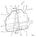
図1に示したのは、本発明に従って形成された連結用ブラケットの斜視図である。 FIG. 1 is a perspective view of a connecting bracket formed in accordance with the present invention.
連結用ブラケット1は、略90°の角度で互いに隣接している肋材側取付面2とスキンパネル側取付面3とを備えている。肋材側取付面2及びスキンパネル側取付面3はいずれも、その概略形状が長方形であり、肋材側取付面2の表面積はスキンパネル側取付面3の表面積の少なくとも3倍の広さを有する。
The connecting
肋材側取付面2の上部領域4に複数の孔が形成されており、図中ではそれら複数の孔のうちの1つにだけ代表として参照符号5を付してある。同様に、スキンパネル側取付面3にも複数の孔が形成されており、図中ではそれら複数の孔のうちの1つにだけ代表として参照符号6を付してある。それらの孔5、6は、シェルセグメントの肋材(図1では不図示)とスキンパネル(図1では不図示)とを、連結用ブラケット1を介して互いに連結する際に、連結用ブラケット1とそれら肋材及びスキンパネルとを、例えばリベットやボルトなどの接合部材を用いて接合する場合に必要とされる孔である。一方、連結用ブラケット1とそれら肋材及びスキンパネルとを、接着剤を用いて接合する場合には、それら孔5、6を形成しないこともある。ただし、接合の冗長度を高めるために、連結用ブラケット1とそれら肋材及びスキンパネルとを、接合部材と接着剤とを併用して接合するようにしてもよい。肋材側取付面2の上部領域4に、2つの略々四半円形状の切欠部7、8が形成されている。それら2つの切欠部7、8は、肋材側取付面2の右上及び左上の隅部に(即ちそれら隅部を切り欠くようにして)形成されている。本発明によれば、連結用ブラケット1は、少なくとも1つのリブ部9を備えている。リブ部9は、肋材側取付面2とスキンパネル側取付面3との両方に亘って形成されており、連結用ブラケット1のそれら2つの取付面2、3を接続している。リブ部9の表面形状は、円錐形を縦割りに二分割した形状に近似した形状であり、2つの側面10、11と、1本の稜線12とを備えている。連結用ブラケット1の一方の端縁13とリブ部9の一方の先端部との間、並びに、連結用ブラケット1の他方の端縁14とリブ部9の他方の先端部との間に、小さな離隔距離15、16が確保されている。
A plurality of holes are formed in the upper region 4 of the saddle member-
連結用ブラケット1は、例えば、平板状の金属板ブランクに適宜の成形加工を施して製作したワンピース部品としてもよい。金属板ブランクの材料としては、例えば、アルミニウム系合金、チタン系合金、それにステンレス鋼系合金の金属板などを用いることができ、また、これらの金属材料を組合せて用いてもよい。或いはまた、連結用ブラケット1は、繊維強化複合材料で製作したワンピース部品としてもよく、例えば、炭素繊維強化エポキシ系樹脂材料及び/または炭素繊維強化熱可塑性合成樹脂材料などを用いて製作するとよい。
The connecting
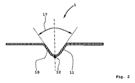
図2に示したのは、図1の切断線II−IIに沿った断面図である。 FIG. 2 is a cross-sectional view taken along a cutting line II-II in FIG.
図2の断面図に示したように、連結用ブラケット1の2つの側面部10、11がリブ部9において互いに成す角度17は70°とすることが好ましい。当該角度17をこの大きさとすることによって、肋材側取付面2とスキンパネル側取付面3との間の捻り剛性が最適なものとなる。稜線12の部分におけるリブ部9の横断面形状は略々半円形状となっている。前記角度17の適当な値は60°〜80°の範囲内の値である。
As shown in the cross-sectional view of FIG. 2, it is preferable that the
図3に示したのは、図1の切断線III−IIIに沿った断面図である。同図に示したように、リブ部9の稜線12と、スキンパネル側取付面3の延展面である水平面とが成す角度18は約100°としてある。当該角度18の値は100°からある程度外れていてもよく、95°〜145°の範囲の値としてもよい。リブ部9はこの角度18をもって、肋材側取付面2からスキンパネル側取付面3まで延在している。尚、肋材側取付面2の端縁13とリブ部9の始端との間の離隔距離15を、スキンパネル側取付面3の端縁14とリブ部9の他方の先端との間の離隔距離16より大きくしておくことが好ましい。
FIG. 3 is a cross-sectional view taken along section line III-III in FIG. As shown in the figure, the
図4に示したのは、本発明に従って構成されたシェルセグメントのうちの、以上に説明した連結用ブラケットを備えた部分の斜視図である。 FIG. 4 is a perspective view of a portion of the shell segment configured in accordance with the present invention, including the connecting bracket described above.
シェルセグメント19は、先ずなによりも、スキンパネル20を備えている。スキンパネル20には複数本の縦方向延在補強材として4本の縦通材21〜24が設けられている。複数本の縦通材21〜24は、それらが設けられているスキンパネル20上に、互いに平行に、略々等間隔で配設されているようにすることが好ましい。縦通材21〜24の各々は、その横断面形状が略々台形であり、スキンパネル20に一体的に形成されている。図示したシェルセグメント19と同様に構成した複数枚のシェルセグメントが、少なくとも2枚、そして通常は4枚、互いに接合されることによって略々筒形の胴体セクションが製作され、その際のシェルセグメントどうしの接合は、縦通材21〜24と平行に延在する縦方向延在接合構造を介したものとなる。更に、こうして製作された複数個の胴体セクションが、横方向延在接合構造が構築されることで互いに接合され、それによって最終的に航空機の胴体セルが完成する。
First of all, the shell segment 19 includes a
図示した座標系25は、図中の様々な構成要素の三次元空間内における姿勢を明示するために示したものである。座標系25のx軸の延在方向は航空機の胴体セルの前後方向であり、従って航空機の飛行方向である。z軸の延在方向は航空機の胴体セルの高さ方向であり、このz軸の矢印の向きは胴体セルの底部即ち床部から上方へ向かう向きである。座標系25のy軸は航空機の不図示の主翼軸の延在方向に対して略々平行に延在している。 The illustrated coordinate system 25 is shown in order to clearly show the postures of various components in the figure in the three-dimensional space. The extending direction of the x-axis of the coordinate system 25 is the longitudinal direction of the fuselage cell of the aircraft, and thus the flight direction of the aircraft. The extending direction of the z-axis is the height direction of the fuselage cell of the aircraft, and the direction of the arrow on the z-axis is the upward direction from the bottom or floor of the fuselage cell. The y axis of the coordinate system 25 extends substantially parallel to the extending direction of the main wing axis (not shown) of the aircraft.
シェルセグメント19には、縦通材21〜24に対して略々直交する方向に延在する横方向延在補強材である肋材26が、本発明に従って構成された複数個の連結用ブラケットを介して固定されており、図4にはそれら連結用ブラケットとして3つの連結用ブラケット27〜29が示されている。図4に示した3つの連結用ブラケット27〜29の構成は、上で図1〜図3を参照して説明した連結用ブラケット1の構成と完全に同一である。3つの連結用ブラケット27〜29と、肋材26と、スキンパネル20とは、接着剤、リベット、ボルトなどの接合要素により接合され、或いはまた、それら接合要素を適宜に併用して接合される。連結用ブラケット27〜29は、各々が、互いに平行に延在している2本の縦通材の間に配設されている。
The shell segment 19 is provided with a plurality of connecting brackets formed in accordance with the present invention. The brim 26 is a laterally extending reinforcing material extending in a direction substantially orthogonal to the longitudinal members 21 to 24. FIG. 4 shows three connecting brackets 27 to 29 as the connecting brackets. The configuration of the three connecting brackets 27 to 29 shown in FIG. 4 is completely the same as the configuration of the connecting
このように、本発明に従って構成された連結用ブラケット27〜29を備えていることから、肋材26に作用する座標系25のy軸の周りの傾動モーメントが、それら連結用ブラケット27〜29によって担持されて、スキンパネル20へ伝達されるようになっており、そのため、肋材26に大きな荷重が作用したときにも、肋材26の傾き並びに捻れ変形が確実に防止される。更に、連結用ブラケット27〜29を備えるならば、肋材26に作用する傾動モーメントを担持するための荷重担持用ブラケットを付加する必要がなく、そのことも利点となっている。
As described above, since the connection brackets 27 to 29 configured according to the present invention are provided, the tilting moment around the y-axis of the coordinate system 25 acting on the saddle member 26 is caused by the connection brackets 27 to 29. Since it is carried and transmitted to the
以上によってシェルセグメント19は、公知構造のものと比べて、大幅に軽量化されると共にその製造に要する製作コストも格段に軽減されている。また、連結用ブラケット27〜29は、肋材26をスキンパネル20に連結するという本来の機能を提供すると共に、肋材26に作用した傾動モーメントを、肋材26からスキンパネル20へ伝達する機能も提供している。
As described above, the shell segment 19 is significantly reduced in weight as compared with a known structure, and the manufacturing cost required for manufacturing the shell segment 19 is significantly reduced. Further, the connecting brackets 27 to 29 provide an original function of connecting the collar member 26 to the
好適な1つの実施の形態に係るシェルセグメント19では、スキンパネル20及び縦通材21〜24のみならず、更に肋材26及び連結用ブラケット27〜29までも、例えば炭素繊維強化エポキシ系樹脂材料などの繊維強化合成樹脂材料で製作するようにしている。これとは別の1つの構成例では、少なくとも連結用ブラケット27〜29だけは、炭素繊維強化熱可塑性合成樹脂材料で製作するようにしている。ただし基本的に、シェルセグメント19の構造は、従来一般的な金属系材料製の構造とすることもでき、例えば、公知のアルミニウム系合金材料を用いた構造とすることもできる。
In the shell segment 19 according to a preferred embodiment, not only the
通常、シェルセグメント19は多数の肋材を備えた構成とされ、そのため、それに応じて非常に多くの連結用ブラケットを備えた構成とされる。シェルセグメント19の長さ方向寸法は、例えば40mもの長さとされることもあり、また、シェルセグメント19の周方向寸法は、例えば10mもの長さとされることもある。一例として、周方向寸法が例えば9mのシェルセグメントを4枚用いて、横断面形状が略々円形状の公知の4枚継ぎ構造の航空機の胴体セクションを製作する場合には、直径が11mを超える大型の胴体セクションを製作することができる(ただしこれは、製作する胴体セクションの横断面形状が略々円形状であり、また、用いる複数枚のシェルセグメントの周方向寸法が互いに略々等しいとした場合の例である)。基本的に、1つの胴体セクションを構成するために用いる複数枚のシェルセグメントは、それらの周方向寸法が互いに異なっていてもよく、更には、各々のシェルセグメントの周方向寸法が局所的に異なっていてもよく、従って、用いるシェルセグメントは、その湾曲形状が円形状ないし円弧形状から逸脱していてもよい。また別法として、胴体セクションを二分割型の構造として、横断面形状が略々半円形状の2枚のシェルセグメントを継ぎ合わせて製作するようにしてもよい。 Usually, the shell segment 19 is configured to include a large number of ribs, and accordingly, includes a very large number of connecting brackets accordingly. The length dimension of the shell segment 19 may be as long as 40 m, for example, and the circumferential dimension of the shell segment 19 may be as long as 10 m, for example. As an example, when a fuselage section of an aircraft having a known four-joint structure having a substantially circular cross section is used by using four shell segments having a circumferential dimension of, for example, 9 m, the diameter exceeds 11 m. A large fuselage section can be manufactured (however, the cross-sectional shape of the fuselage section to be manufactured is substantially circular, and the circumferential dimensions of the plurality of shell segments used are substantially equal to each other) Example). Basically, the plurality of shell segments used to form one fuselage section may have different circumferential dimensions, and each shell segment may have a locally different circumferential dimension. Therefore, the shell segment to be used may have a curved shape deviating from a circular shape or an arc shape. Alternatively, the body section may have a two-part structure, and two shell segments having a substantially semicircular cross-sectional shape may be joined together.
1 連結用ブラケット
2 肋材側取付面
3 スキンパネル側取付面
4 肋材側取付面の上部領域
5 肋材側取付面の孔
6 スキンパネル側取付面の孔
7 肋材側取付面の切欠部
8 肋材側取付面の切欠部
9 リブ部
10 側面
11 側面
12 稜線
13 肋材側取付面の端縁
14 スキンパネル側取付面の端縁
15 リブ部と端縁との間の離隔距離
16 リブ部と端縁との間の離隔距離
17 リブ部において2つの側面が成す角度
18 稜線とスキンパネル側取付面とが成す角度
19 シェルセグメント
20 スキンパネル
21 縦通材
22 縦通材
23 縦通材
24 縦通材
25 座標系
26 肋材
27 連結用ブラケット
28 連結用ブラケット
29 連結用ブラケット
DESCRIPTION OF
Claims (10)
前記少なくとも1本の横方向延在補強材と前記少なくとも1枚のスキンパネル(20)とは少なくとも1つの連結用ブラケット(1、27〜29)を介して連結されており、該少なくとも1つの連結用ブラケット(1、27〜29)は少なくとも1つのリブ部(9)を備えていることを特徴とするシェルセグメント(19)。 A shell segment for producing a fuselage cell section constituting an aircraft fuselage cell, comprising at least one skin panel (20) and a plurality of longitudinal members (21-24, for example) provided on the skin panel. ) And the like, and at least one transversely extending reinforcing material such as a brazing material (26) extending in a direction substantially orthogonal to the vertical extending reinforcing material. In the provided shell segment (19),
The at least one laterally extending reinforcing member and the at least one skin panel (20) are connected via at least one connection bracket (1, 27 to 29), and the at least one connection Shell segment (19), characterized in that the bracket (1, 27-29) has at least one rib part (9).
Applications Claiming Priority (5)
| Application Number | Priority Date | Filing Date | Title |
|---|---|---|---|
| US22593309P | 2009-07-16 | 2009-07-16 | |
| US61/225,933 | 2009-07-16 | ||
| DE102009033444.0 | 2009-07-16 | ||
| DE102009033444A DE102009033444A1 (en) | 2009-07-16 | 2009-07-16 | Shell segment for producing a fuselage cell section for a fuselage cell of an aircraft |
| PCT/EP2010/060194 WO2011006954A2 (en) | 2009-07-16 | 2010-07-15 | Shell segment for producing a fuselage cell section for a fuselage cell of an airplane |
Publications (1)
| Publication Number | Publication Date |
|---|---|
| JP2012532796A true JP2012532796A (en) | 2012-12-20 |
Family
ID=43383874
Family Applications (1)
| Application Number | Title | Priority Date | Filing Date |
|---|---|---|---|
| JP2012520034A Pending JP2012532796A (en) | 2009-07-16 | 2010-07-15 | Shell segments for making the fuselage cell sections that make up the fuselage cell of an aircraft |
Country Status (8)
| Country | Link |
|---|---|
| US (1) | US8800928B2 (en) |
| EP (1) | EP2454150B1 (en) |
| JP (1) | JP2012532796A (en) |
| CN (1) | CN102481972B (en) |
| CA (1) | CA2767945A1 (en) |
| DE (1) | DE102009033444A1 (en) |
| RU (1) | RU2494007C1 (en) |
| WO (1) | WO2011006954A2 (en) |
Families Citing this family (10)
| Publication number | Priority date | Publication date | Assignee | Title |
|---|---|---|---|---|
| ES2400771B1 (en) * | 2011-03-30 | 2014-02-14 | Airbus Operations S.L. | AIRCRAFT FUSELAGE WITH HIGHLY RESISTANT NOTEBOOKS. |
| EP3083395B1 (en) * | 2013-12-20 | 2021-09-08 | Saab Ab | Stiffening element and reinforced structure |
| EP2905225B1 (en) * | 2014-02-07 | 2018-10-10 | Airbus Operations GmbH | Attachment structure of an aircraft |
| WO2015170090A1 (en) * | 2014-05-07 | 2015-11-12 | Bae Systems Plc | Aircraft fuel tank |
| DE102015105170A1 (en) * | 2015-04-02 | 2016-10-06 | Airbus Operations Gmbh | Stiffening structure and method for stiffening the skin panel of an aircraft fuselage |
| DE102015220642A1 (en) * | 2015-10-22 | 2017-04-27 | Airbus Defence and Space GmbH | Structural assembly, aerospace vehicle and method of fabricating a structural assembly |
| CN105523052B (en) * | 2015-12-20 | 2018-02-16 | 沈阳市沈飞专用设备厂 | A kind of carbon fiber skin structure |
| US10427778B2 (en) * | 2016-03-14 | 2019-10-01 | The Boeing Company | Heat shield assembly and method |
| CN107434028A (en) * | 2016-05-25 | 2017-12-05 | 天津宏宇天翔科技有限公司 | A kind of fuselage of full open type unmanned plane |
| FR3105168B1 (en) * | 2019-12-19 | 2022-10-28 | Airbus Operations Sas | Stabilizer intended to flexibly assemble a frame element and a stiffener for an aircraft fuselage. |
Citations (10)
| Publication number | Priority date | Publication date | Assignee | Title |
|---|---|---|---|---|
| EP0048191A1 (en) * | 1980-09-09 | 1982-03-24 | Aerospatiale Societe Nationale Industrielle | Airship fuselage structure resistant to longitudinal cracks of the skin |
| DE102006060364A1 (en) * | 2006-12-20 | 2008-06-26 | Airbus Deutschland Gmbh | Fuselage component for an aircraft or spacecraft comprises a heat stopper having low heat conductivity for connecting a structural part to the skin |
| WO2008119701A1 (en) * | 2007-03-30 | 2008-10-09 | Airbus Operations Gmbh | Method for producing a structural component |
| WO2008129156A1 (en) * | 2007-02-21 | 2008-10-30 | Coriolis Composites | Method and device for making parts of a composite material, in particular sections of an aircraft fuselage |
| WO2009037006A1 (en) * | 2007-09-18 | 2009-03-26 | Airbus Operations Gmbh | Structural component and fuselage of an aircraft or spacecraft |
| WO2009056643A2 (en) * | 2007-10-31 | 2009-05-07 | Airbus Operations Gmbh | Structure, especially a fuselage structure of an aircraft or a spacecraft |
| FR2923800A1 (en) * | 2007-11-16 | 2009-05-22 | Airbus France Sas | Connection device i.e. clip device, for e.g. frame, of aircraft, has element with weakened compression zone to absorb impacts subjected by external surface of fuselage skin and another element resisting to forces on internal surface of skin |
| WO2009065587A1 (en) * | 2007-11-20 | 2009-05-28 | Airbus Deutschland Gmbh | Coupling device for joining fuselage sections, combination of a coupling device and at least one fuselage section, and method for producing said coupling device |
| JP2010531259A (en) * | 2007-06-25 | 2010-09-24 | エアバス・オペレーションズ・ゲーエムベーハー | Reinforced profile connecting method and structural parts |
| JP2010538889A (en) * | 2007-09-18 | 2010-12-16 | エアバス・オペレーションズ・ゲーエムベーハー | Method for strengthening structural elements and external skins |
Family Cites Families (2)
| Publication number | Priority date | Publication date | Assignee | Title |
|---|---|---|---|---|
| RU2007330C1 (en) * | 1992-02-07 | 1994-02-15 | Самарский государственный аэрокосмический университет | Aircraft baggage compartment |
| ES2352941B1 (en) * | 2008-05-16 | 2012-01-25 | Airbus Operations, S.L. | INTEGRATED AIRCRAFT STRUCTURE IN COMPOSITE MATERIAL |
-
2009
- 2009-07-16 DE DE102009033444A patent/DE102009033444A1/en not_active Ceased
-
2010
- 2010-07-15 RU RU2012105330/11A patent/RU2494007C1/en not_active IP Right Cessation
- 2010-07-15 CA CA2767945A patent/CA2767945A1/en not_active Abandoned
- 2010-07-15 US US13/384,033 patent/US8800928B2/en active Active
- 2010-07-15 CN CN201080031939.4A patent/CN102481972B/en not_active Expired - Fee Related
- 2010-07-15 EP EP10732376.8A patent/EP2454150B1/en not_active Not-in-force
- 2010-07-15 WO PCT/EP2010/060194 patent/WO2011006954A2/en active Application Filing
- 2010-07-15 JP JP2012520034A patent/JP2012532796A/en active Pending
Patent Citations (15)
| Publication number | Priority date | Publication date | Assignee | Title |
|---|---|---|---|---|
| EP0048191A1 (en) * | 1980-09-09 | 1982-03-24 | Aerospatiale Societe Nationale Industrielle | Airship fuselage structure resistant to longitudinal cracks of the skin |
| DE102006060364A1 (en) * | 2006-12-20 | 2008-06-26 | Airbus Deutschland Gmbh | Fuselage component for an aircraft or spacecraft comprises a heat stopper having low heat conductivity for connecting a structural part to the skin |
| JP2010519120A (en) * | 2007-02-21 | 2010-06-03 | コリオリ コンポジテ | Method and apparatus for manufacturing parts, in particular aircraft fuselage parts from composite materials |
| WO2008129156A1 (en) * | 2007-02-21 | 2008-10-30 | Coriolis Composites | Method and device for making parts of a composite material, in particular sections of an aircraft fuselage |
| JP2010523357A (en) * | 2007-03-30 | 2010-07-15 | エアバス・オペレーションズ・ゲーエムベーハー | Manufacturing method of structural parts |
| WO2008119701A1 (en) * | 2007-03-30 | 2008-10-09 | Airbus Operations Gmbh | Method for producing a structural component |
| JP2010531259A (en) * | 2007-06-25 | 2010-09-24 | エアバス・オペレーションズ・ゲーエムベーハー | Reinforced profile connecting method and structural parts |
| WO2009037006A1 (en) * | 2007-09-18 | 2009-03-26 | Airbus Operations Gmbh | Structural component and fuselage of an aircraft or spacecraft |
| JP2010538890A (en) * | 2007-09-18 | 2010-12-16 | エアバス・オペレーションズ・ゲーエムベーハー | Structural elements and fuselage of aircraft or spacecraft |
| JP2010538889A (en) * | 2007-09-18 | 2010-12-16 | エアバス・オペレーションズ・ゲーエムベーハー | Method for strengthening structural elements and external skins |
| WO2009056643A2 (en) * | 2007-10-31 | 2009-05-07 | Airbus Operations Gmbh | Structure, especially a fuselage structure of an aircraft or a spacecraft |
| JP2011500452A (en) * | 2007-10-31 | 2011-01-06 | エアバス・オペレーションズ・ゲーエムベーハー | Structure, especially fuselage structure of aircraft or spacecraft |
| FR2923800A1 (en) * | 2007-11-16 | 2009-05-22 | Airbus France Sas | Connection device i.e. clip device, for e.g. frame, of aircraft, has element with weakened compression zone to absorb impacts subjected by external surface of fuselage skin and another element resisting to forces on internal surface of skin |
| WO2009065587A1 (en) * | 2007-11-20 | 2009-05-28 | Airbus Deutschland Gmbh | Coupling device for joining fuselage sections, combination of a coupling device and at least one fuselage section, and method for producing said coupling device |
| JP2011502886A (en) * | 2007-11-20 | 2011-01-27 | エアバス・オペレーションズ・ゲーエムベーハー | Coupling device for coupling fuselage sections, coupling of the coupling device to at least one fuselage section and method for manufacturing the coupling device |
Also Published As
| Publication number | Publication date |
|---|---|
| EP2454150A2 (en) | 2012-05-23 |
| US20120132756A1 (en) | 2012-05-31 |
| WO2011006954A2 (en) | 2011-01-20 |
| EP2454150B1 (en) | 2015-07-01 |
| US8800928B2 (en) | 2014-08-12 |
| CA2767945A1 (en) | 2011-01-20 |
| WO2011006954A3 (en) | 2011-07-07 |
| DE102009033444A1 (en) | 2011-01-27 |
| RU2494007C1 (en) | 2013-09-27 |
| RU2012105330A (en) | 2013-08-27 |
| CN102481972A (en) | 2012-05-30 |
| CN102481972B (en) | 2015-12-16 |
Similar Documents
| Publication | Publication Date | Title |
|---|---|---|
| JP2012532796A (en) | Shell segments for making the fuselage cell sections that make up the fuselage cell of an aircraft | |
| US10046848B2 (en) | Aircraft rear structure | |
| JP5608886B2 (en) | Aircraft cabin floor structure, system and method | |
| EP2371704B1 (en) | Structure for the fuselage rear end | |
| RU2496678C2 (en) | Structural assembly and structure used, in particular, in aircraft engineering | |
| EP3106383B1 (en) | Fractal stiffening | |
| EP2444315B1 (en) | Metal fittings for engaging the vertical tailplane of an aircraft | |
| CN101959753B (en) | Transverse butt connection between two fuselage sections | |
| WO2008109711A1 (en) | Aircraft floor to fuselage attachment | |
| US7810758B2 (en) | Arrangement for coupling a coupling pivot for a trimmable horizontal stabiliser to the tail fuselage of an aircraft | |
| JP2012520787A (en) | Cell structure of hybrid aircraft body | |
| EP3159247A1 (en) | Hybrid spare tire receptacle for a vehicle | |
| US9394001B2 (en) | Diagonal strut device, method for manufacturing same and motor vehicle underfloor reinforced by means of the diagonal strut device | |
| JP2010533622A (en) | Profile part comprising at least one hollow part | |
| US9896180B2 (en) | Method for manufacturing a load bearing structure and such a load bearing structure | |
| JP6054105B2 (en) | Aircraft fuselage frame elements | |
| JP2013056662A5 (en) | ||
| EP3040263B1 (en) | Tail cone of an aircraft | |
| US10875625B2 (en) | Co-cured spar and stringer center wing box | |
| US20210101689A1 (en) | Engine pylon for coupling a jet engine to a wing of an aircraft | |
| US20160137299A1 (en) | Multipart fastening device for fastening a device to a reinforcing element and to the outer skin of a vehicle | |
| US20160318595A1 (en) | Assembling of structural elements in aviation | |
| CN106476879B (en) | Turn to supporting beam structure | |
| EP2593360B1 (en) | Beam for an aircraft fuselage floor | |
| US20170305473A1 (en) | Axle carrier with improved load path |
Legal Events
| Date | Code | Title | Description |
|---|---|---|---|
| A977 | Report on retrieval |
Free format text: JAPANESE INTERMEDIATE CODE: A971007 Effective date: 20130628 |
|
| A131 | Notification of reasons for refusal |
Free format text: JAPANESE INTERMEDIATE CODE: A131 Effective date: 20130702 |
|
| A02 | Decision of refusal |
Free format text: JAPANESE INTERMEDIATE CODE: A02 Effective date: 20131217 |