JP2012532662A - Hip apparatus and method - Google Patents
Hip apparatus and method Download PDFInfo
- Publication number
- JP2012532662A JP2012532662A JP2012519512A JP2012519512A JP2012532662A JP 2012532662 A JP2012532662 A JP 2012532662A JP 2012519512 A JP2012519512 A JP 2012519512A JP 2012519512 A JP2012519512 A JP 2012519512A JP 2012532662 A JP2012532662 A JP 2012532662A
- Authority
- JP
- Japan
- Prior art keywords
- medical device
- state
- holding
- artificial
- hip joint
- Prior art date
- Legal status (The legal status is an assumption and is not a legal conclusion. Google has not performed a legal analysis and makes no representation as to the accuracy of the status listed.)
- Pending
Links
Images


Classifications
-
- A—HUMAN NECESSITIES
- A61—MEDICAL OR VETERINARY SCIENCE; HYGIENE
- A61F—FILTERS IMPLANTABLE INTO BLOOD VESSELS; PROSTHESES; DEVICES PROVIDING PATENCY TO, OR PREVENTING COLLAPSING OF, TUBULAR STRUCTURES OF THE BODY, e.g. STENTS; ORTHOPAEDIC, NURSING OR CONTRACEPTIVE DEVICES; FOMENTATION; TREATMENT OR PROTECTION OF EYES OR EARS; BANDAGES, DRESSINGS OR ABSORBENT PADS; FIRST-AID KITS
- A61F2/00—Filters implantable into blood vessels; Prostheses, i.e. artificial substitutes or replacements for parts of the body; Appliances for connecting them with the body; Devices providing patency to, or preventing collapsing of, tubular structures of the body, e.g. stents
- A61F2/02—Prostheses implantable into the body
- A61F2/30—Joints
- A61F2/32—Joints for the hip
- A61F2/34—Acetabular cups
-
- A—HUMAN NECESSITIES
- A61—MEDICAL OR VETERINARY SCIENCE; HYGIENE
- A61F—FILTERS IMPLANTABLE INTO BLOOD VESSELS; PROSTHESES; DEVICES PROVIDING PATENCY TO, OR PREVENTING COLLAPSING OF, TUBULAR STRUCTURES OF THE BODY, e.g. STENTS; ORTHOPAEDIC, NURSING OR CONTRACEPTIVE DEVICES; FOMENTATION; TREATMENT OR PROTECTION OF EYES OR EARS; BANDAGES, DRESSINGS OR ABSORBENT PADS; FIRST-AID KITS
- A61F2/00—Filters implantable into blood vessels; Prostheses, i.e. artificial substitutes or replacements for parts of the body; Appliances for connecting them with the body; Devices providing patency to, or preventing collapsing of, tubular structures of the body, e.g. stents
- A61F2/02—Prostheses implantable into the body
- A61F2/30—Joints
- A61F2/32—Joints for the hip
- A61F2/36—Femoral heads ; Femoral endoprostheses
- A61F2/3601—Femoral heads ; Femoral endoprostheses for replacing only the epiphyseal or metaphyseal parts of the femur, e.g. endoprosthetic femoral heads or necks directly fixed to the natural femur by internal fixation devices
- A61F2/3603—Femoral heads ; Femoral endoprostheses for replacing only the epiphyseal or metaphyseal parts of the femur, e.g. endoprosthetic femoral heads or necks directly fixed to the natural femur by internal fixation devices implanted without ablation of the whole natural femoral head
-
- A—HUMAN NECESSITIES
- A61—MEDICAL OR VETERINARY SCIENCE; HYGIENE
- A61F—FILTERS IMPLANTABLE INTO BLOOD VESSELS; PROSTHESES; DEVICES PROVIDING PATENCY TO, OR PREVENTING COLLAPSING OF, TUBULAR STRUCTURES OF THE BODY, e.g. STENTS; ORTHOPAEDIC, NURSING OR CONTRACEPTIVE DEVICES; FOMENTATION; TREATMENT OR PROTECTION OF EYES OR EARS; BANDAGES, DRESSINGS OR ABSORBENT PADS; FIRST-AID KITS
- A61F2/00—Filters implantable into blood vessels; Prostheses, i.e. artificial substitutes or replacements for parts of the body; Appliances for connecting them with the body; Devices providing patency to, or preventing collapsing of, tubular structures of the body, e.g. stents
- A61F2/02—Prostheses implantable into the body
- A61F2/30—Joints
- A61F2/32—Joints for the hip
- A61F2/36—Femoral heads ; Femoral endoprostheses
- A61F2/3609—Femoral heads or necks; Connections of endoprosthetic heads or necks to endoprosthetic femoral shafts
-
- A—HUMAN NECESSITIES
- A61—MEDICAL OR VETERINARY SCIENCE; HYGIENE
- A61B—DIAGNOSIS; SURGERY; IDENTIFICATION
- A61B17/00—Surgical instruments, devices or methods, e.g. tourniquets
- A61B17/56—Surgical instruments or methods for treatment of bones or joints; Devices specially adapted therefor
- A61B17/58—Surgical instruments or methods for treatment of bones or joints; Devices specially adapted therefor for osteosynthesis, e.g. bone plates, screws, setting implements or the like
- A61B17/68—Internal fixation devices, including fasteners and spinal fixators, even if a part thereof projects from the skin
- A61B17/74—Devices for the head or neck or trochanter of the femur
-
- A—HUMAN NECESSITIES
- A61—MEDICAL OR VETERINARY SCIENCE; HYGIENE
- A61F—FILTERS IMPLANTABLE INTO BLOOD VESSELS; PROSTHESES; DEVICES PROVIDING PATENCY TO, OR PREVENTING COLLAPSING OF, TUBULAR STRUCTURES OF THE BODY, e.g. STENTS; ORTHOPAEDIC, NURSING OR CONTRACEPTIVE DEVICES; FOMENTATION; TREATMENT OR PROTECTION OF EYES OR EARS; BANDAGES, DRESSINGS OR ABSORBENT PADS; FIRST-AID KITS
- A61F2/00—Filters implantable into blood vessels; Prostheses, i.e. artificial substitutes or replacements for parts of the body; Appliances for connecting them with the body; Devices providing patency to, or preventing collapsing of, tubular structures of the body, e.g. stents
- A61F2/02—Prostheses implantable into the body
- A61F2/30—Joints
- A61F2002/30001—Additional features of subject-matter classified in A61F2/28, A61F2/30 and subgroups thereof
- A61F2002/30003—Material related properties of the prosthesis or of a coating on the prosthesis
- A61F2002/3006—Properties of materials and coating materials
- A61F2002/30079—Properties of materials and coating materials magnetic
-
- A—HUMAN NECESSITIES
- A61—MEDICAL OR VETERINARY SCIENCE; HYGIENE
- A61F—FILTERS IMPLANTABLE INTO BLOOD VESSELS; PROSTHESES; DEVICES PROVIDING PATENCY TO, OR PREVENTING COLLAPSING OF, TUBULAR STRUCTURES OF THE BODY, e.g. STENTS; ORTHOPAEDIC, NURSING OR CONTRACEPTIVE DEVICES; FOMENTATION; TREATMENT OR PROTECTION OF EYES OR EARS; BANDAGES, DRESSINGS OR ABSORBENT PADS; FIRST-AID KITS
- A61F2/00—Filters implantable into blood vessels; Prostheses, i.e. artificial substitutes or replacements for parts of the body; Appliances for connecting them with the body; Devices providing patency to, or preventing collapsing of, tubular structures of the body, e.g. stents
- A61F2/02—Prostheses implantable into the body
- A61F2/30—Joints
- A61F2002/30001—Additional features of subject-matter classified in A61F2/28, A61F2/30 and subgroups thereof
- A61F2002/30316—The prosthesis having different structural features at different locations within the same prosthesis; Connections between prosthetic parts; Special structural features of bone or joint prostheses not otherwise provided for
- A61F2002/30329—Connections or couplings between prosthetic parts, e.g. between modular parts; Connecting elements
- A61F2002/30383—Connections or couplings between prosthetic parts, e.g. between modular parts; Connecting elements made by laterally inserting a protrusion, e.g. a rib into a complementarily-shaped groove
- A61F2002/30387—Dovetail connection
-
- A—HUMAN NECESSITIES
- A61—MEDICAL OR VETERINARY SCIENCE; HYGIENE
- A61F—FILTERS IMPLANTABLE INTO BLOOD VESSELS; PROSTHESES; DEVICES PROVIDING PATENCY TO, OR PREVENTING COLLAPSING OF, TUBULAR STRUCTURES OF THE BODY, e.g. STENTS; ORTHOPAEDIC, NURSING OR CONTRACEPTIVE DEVICES; FOMENTATION; TREATMENT OR PROTECTION OF EYES OR EARS; BANDAGES, DRESSINGS OR ABSORBENT PADS; FIRST-AID KITS
- A61F2/00—Filters implantable into blood vessels; Prostheses, i.e. artificial substitutes or replacements for parts of the body; Appliances for connecting them with the body; Devices providing patency to, or preventing collapsing of, tubular structures of the body, e.g. stents
- A61F2/02—Prostheses implantable into the body
- A61F2/30—Joints
- A61F2002/30001—Additional features of subject-matter classified in A61F2/28, A61F2/30 and subgroups thereof
- A61F2002/30316—The prosthesis having different structural features at different locations within the same prosthesis; Connections between prosthetic parts; Special structural features of bone or joint prostheses not otherwise provided for
- A61F2002/30329—Connections or couplings between prosthetic parts, e.g. between modular parts; Connecting elements
- A61F2002/30433—Connections or couplings between prosthetic parts, e.g. between modular parts; Connecting elements using additional screws, bolts, dowels, rivets or washers e.g. connecting screws
-
- A—HUMAN NECESSITIES
- A61—MEDICAL OR VETERINARY SCIENCE; HYGIENE
- A61F—FILTERS IMPLANTABLE INTO BLOOD VESSELS; PROSTHESES; DEVICES PROVIDING PATENCY TO, OR PREVENTING COLLAPSING OF, TUBULAR STRUCTURES OF THE BODY, e.g. STENTS; ORTHOPAEDIC, NURSING OR CONTRACEPTIVE DEVICES; FOMENTATION; TREATMENT OR PROTECTION OF EYES OR EARS; BANDAGES, DRESSINGS OR ABSORBENT PADS; FIRST-AID KITS
- A61F2/00—Filters implantable into blood vessels; Prostheses, i.e. artificial substitutes or replacements for parts of the body; Appliances for connecting them with the body; Devices providing patency to, or preventing collapsing of, tubular structures of the body, e.g. stents
- A61F2/02—Prostheses implantable into the body
- A61F2/30—Joints
- A61F2002/30001—Additional features of subject-matter classified in A61F2/28, A61F2/30 and subgroups thereof
- A61F2002/30316—The prosthesis having different structural features at different locations within the same prosthesis; Connections between prosthetic parts; Special structural features of bone or joint prostheses not otherwise provided for
- A61F2002/30329—Connections or couplings between prosthetic parts, e.g. between modular parts; Connecting elements
- A61F2002/30462—Connections or couplings between prosthetic parts, e.g. between modular parts; Connecting elements retained or tied with a rope, string, thread, wire or cable
-
- A—HUMAN NECESSITIES
- A61—MEDICAL OR VETERINARY SCIENCE; HYGIENE
- A61F—FILTERS IMPLANTABLE INTO BLOOD VESSELS; PROSTHESES; DEVICES PROVIDING PATENCY TO, OR PREVENTING COLLAPSING OF, TUBULAR STRUCTURES OF THE BODY, e.g. STENTS; ORTHOPAEDIC, NURSING OR CONTRACEPTIVE DEVICES; FOMENTATION; TREATMENT OR PROTECTION OF EYES OR EARS; BANDAGES, DRESSINGS OR ABSORBENT PADS; FIRST-AID KITS
- A61F2/00—Filters implantable into blood vessels; Prostheses, i.e. artificial substitutes or replacements for parts of the body; Appliances for connecting them with the body; Devices providing patency to, or preventing collapsing of, tubular structures of the body, e.g. stents
- A61F2/02—Prostheses implantable into the body
- A61F2/30—Joints
- A61F2002/30001—Additional features of subject-matter classified in A61F2/28, A61F2/30 and subgroups thereof
- A61F2002/30316—The prosthesis having different structural features at different locations within the same prosthesis; Connections between prosthetic parts; Special structural features of bone or joint prostheses not otherwise provided for
- A61F2002/30329—Connections or couplings between prosthetic parts, e.g. between modular parts; Connecting elements
- A61F2002/30476—Connections or couplings between prosthetic parts, e.g. between modular parts; Connecting elements locked by an additional locking mechanism
- A61F2002/30492—Connections or couplings between prosthetic parts, e.g. between modular parts; Connecting elements locked by an additional locking mechanism using a locking pin
-
- A—HUMAN NECESSITIES
- A61—MEDICAL OR VETERINARY SCIENCE; HYGIENE
- A61F—FILTERS IMPLANTABLE INTO BLOOD VESSELS; PROSTHESES; DEVICES PROVIDING PATENCY TO, OR PREVENTING COLLAPSING OF, TUBULAR STRUCTURES OF THE BODY, e.g. STENTS; ORTHOPAEDIC, NURSING OR CONTRACEPTIVE DEVICES; FOMENTATION; TREATMENT OR PROTECTION OF EYES OR EARS; BANDAGES, DRESSINGS OR ABSORBENT PADS; FIRST-AID KITS
- A61F2/00—Filters implantable into blood vessels; Prostheses, i.e. artificial substitutes or replacements for parts of the body; Appliances for connecting them with the body; Devices providing patency to, or preventing collapsing of, tubular structures of the body, e.g. stents
- A61F2/02—Prostheses implantable into the body
- A61F2/30—Joints
- A61F2002/30001—Additional features of subject-matter classified in A61F2/28, A61F2/30 and subgroups thereof
- A61F2002/30316—The prosthesis having different structural features at different locations within the same prosthesis; Connections between prosthetic parts; Special structural features of bone or joint prostheses not otherwise provided for
- A61F2002/30329—Connections or couplings between prosthetic parts, e.g. between modular parts; Connecting elements
- A61F2002/30476—Connections or couplings between prosthetic parts, e.g. between modular parts; Connecting elements locked by an additional locking mechanism
- A61F2002/30495—Connections or couplings between prosthetic parts, e.g. between modular parts; Connecting elements locked by an additional locking mechanism using a locking ring
-
- A—HUMAN NECESSITIES
- A61—MEDICAL OR VETERINARY SCIENCE; HYGIENE
- A61F—FILTERS IMPLANTABLE INTO BLOOD VESSELS; PROSTHESES; DEVICES PROVIDING PATENCY TO, OR PREVENTING COLLAPSING OF, TUBULAR STRUCTURES OF THE BODY, e.g. STENTS; ORTHOPAEDIC, NURSING OR CONTRACEPTIVE DEVICES; FOMENTATION; TREATMENT OR PROTECTION OF EYES OR EARS; BANDAGES, DRESSINGS OR ABSORBENT PADS; FIRST-AID KITS
- A61F2/00—Filters implantable into blood vessels; Prostheses, i.e. artificial substitutes or replacements for parts of the body; Appliances for connecting them with the body; Devices providing patency to, or preventing collapsing of, tubular structures of the body, e.g. stents
- A61F2/02—Prostheses implantable into the body
- A61F2/30—Joints
- A61F2002/30001—Additional features of subject-matter classified in A61F2/28, A61F2/30 and subgroups thereof
- A61F2002/30316—The prosthesis having different structural features at different locations within the same prosthesis; Connections between prosthetic parts; Special structural features of bone or joint prostheses not otherwise provided for
- A61F2002/30329—Connections or couplings between prosthetic parts, e.g. between modular parts; Connecting elements
- A61F2002/30476—Connections or couplings between prosthetic parts, e.g. between modular parts; Connecting elements locked by an additional locking mechanism
- A61F2002/305—Snap connection
-
- A—HUMAN NECESSITIES
- A61—MEDICAL OR VETERINARY SCIENCE; HYGIENE
- A61F—FILTERS IMPLANTABLE INTO BLOOD VESSELS; PROSTHESES; DEVICES PROVIDING PATENCY TO, OR PREVENTING COLLAPSING OF, TUBULAR STRUCTURES OF THE BODY, e.g. STENTS; ORTHOPAEDIC, NURSING OR CONTRACEPTIVE DEVICES; FOMENTATION; TREATMENT OR PROTECTION OF EYES OR EARS; BANDAGES, DRESSINGS OR ABSORBENT PADS; FIRST-AID KITS
- A61F2/00—Filters implantable into blood vessels; Prostheses, i.e. artificial substitutes or replacements for parts of the body; Appliances for connecting them with the body; Devices providing patency to, or preventing collapsing of, tubular structures of the body, e.g. stents
- A61F2/02—Prostheses implantable into the body
- A61F2/30—Joints
- A61F2002/30001—Additional features of subject-matter classified in A61F2/28, A61F2/30 and subgroups thereof
- A61F2002/30316—The prosthesis having different structural features at different locations within the same prosthesis; Connections between prosthetic parts; Special structural features of bone or joint prostheses not otherwise provided for
- A61F2002/30329—Connections or couplings between prosthetic parts, e.g. between modular parts; Connecting elements
- A61F2002/30476—Connections or couplings between prosthetic parts, e.g. between modular parts; Connecting elements locked by an additional locking mechanism
- A61F2002/30507—Connections or couplings between prosthetic parts, e.g. between modular parts; Connecting elements locked by an additional locking mechanism using a threaded locking member, e.g. a locking screw or a set screw
-
- A—HUMAN NECESSITIES
- A61—MEDICAL OR VETERINARY SCIENCE; HYGIENE
- A61F—FILTERS IMPLANTABLE INTO BLOOD VESSELS; PROSTHESES; DEVICES PROVIDING PATENCY TO, OR PREVENTING COLLAPSING OF, TUBULAR STRUCTURES OF THE BODY, e.g. STENTS; ORTHOPAEDIC, NURSING OR CONTRACEPTIVE DEVICES; FOMENTATION; TREATMENT OR PROTECTION OF EYES OR EARS; BANDAGES, DRESSINGS OR ABSORBENT PADS; FIRST-AID KITS
- A61F2/00—Filters implantable into blood vessels; Prostheses, i.e. artificial substitutes or replacements for parts of the body; Appliances for connecting them with the body; Devices providing patency to, or preventing collapsing of, tubular structures of the body, e.g. stents
- A61F2/02—Prostheses implantable into the body
- A61F2/30—Joints
- A61F2002/30001—Additional features of subject-matter classified in A61F2/28, A61F2/30 and subgroups thereof
- A61F2002/30316—The prosthesis having different structural features at different locations within the same prosthesis; Connections between prosthetic parts; Special structural features of bone or joint prostheses not otherwise provided for
- A61F2002/30535—Special structural features of bone or joint prostheses not otherwise provided for
- A61F2002/30537—Special structural features of bone or joint prostheses not otherwise provided for adjustable
-
- A—HUMAN NECESSITIES
- A61—MEDICAL OR VETERINARY SCIENCE; HYGIENE
- A61F—FILTERS IMPLANTABLE INTO BLOOD VESSELS; PROSTHESES; DEVICES PROVIDING PATENCY TO, OR PREVENTING COLLAPSING OF, TUBULAR STRUCTURES OF THE BODY, e.g. STENTS; ORTHOPAEDIC, NURSING OR CONTRACEPTIVE DEVICES; FOMENTATION; TREATMENT OR PROTECTION OF EYES OR EARS; BANDAGES, DRESSINGS OR ABSORBENT PADS; FIRST-AID KITS
- A61F2/00—Filters implantable into blood vessels; Prostheses, i.e. artificial substitutes or replacements for parts of the body; Appliances for connecting them with the body; Devices providing patency to, or preventing collapsing of, tubular structures of the body, e.g. stents
- A61F2/02—Prostheses implantable into the body
- A61F2/30—Joints
- A61F2002/30001—Additional features of subject-matter classified in A61F2/28, A61F2/30 and subgroups thereof
- A61F2002/30316—The prosthesis having different structural features at different locations within the same prosthesis; Connections between prosthetic parts; Special structural features of bone or joint prostheses not otherwise provided for
- A61F2002/30535—Special structural features of bone or joint prostheses not otherwise provided for
- A61F2002/30558—Force-limiting means
-
- A—HUMAN NECESSITIES
- A61—MEDICAL OR VETERINARY SCIENCE; HYGIENE
- A61F—FILTERS IMPLANTABLE INTO BLOOD VESSELS; PROSTHESES; DEVICES PROVIDING PATENCY TO, OR PREVENTING COLLAPSING OF, TUBULAR STRUCTURES OF THE BODY, e.g. STENTS; ORTHOPAEDIC, NURSING OR CONTRACEPTIVE DEVICES; FOMENTATION; TREATMENT OR PROTECTION OF EYES OR EARS; BANDAGES, DRESSINGS OR ABSORBENT PADS; FIRST-AID KITS
- A61F2/00—Filters implantable into blood vessels; Prostheses, i.e. artificial substitutes or replacements for parts of the body; Appliances for connecting them with the body; Devices providing patency to, or preventing collapsing of, tubular structures of the body, e.g. stents
- A61F2/02—Prostheses implantable into the body
- A61F2/30—Joints
- A61F2002/30001—Additional features of subject-matter classified in A61F2/28, A61F2/30 and subgroups thereof
- A61F2002/30316—The prosthesis having different structural features at different locations within the same prosthesis; Connections between prosthetic parts; Special structural features of bone or joint prostheses not otherwise provided for
- A61F2002/30535—Special structural features of bone or joint prostheses not otherwise provided for
- A61F2002/30561—Special structural features of bone or joint prostheses not otherwise provided for breakable or frangible
-
- A—HUMAN NECESSITIES
- A61—MEDICAL OR VETERINARY SCIENCE; HYGIENE
- A61F—FILTERS IMPLANTABLE INTO BLOOD VESSELS; PROSTHESES; DEVICES PROVIDING PATENCY TO, OR PREVENTING COLLAPSING OF, TUBULAR STRUCTURES OF THE BODY, e.g. STENTS; ORTHOPAEDIC, NURSING OR CONTRACEPTIVE DEVICES; FOMENTATION; TREATMENT OR PROTECTION OF EYES OR EARS; BANDAGES, DRESSINGS OR ABSORBENT PADS; FIRST-AID KITS
- A61F2/00—Filters implantable into blood vessels; Prostheses, i.e. artificial substitutes or replacements for parts of the body; Appliances for connecting them with the body; Devices providing patency to, or preventing collapsing of, tubular structures of the body, e.g. stents
- A61F2/02—Prostheses implantable into the body
- A61F2/30—Joints
- A61F2002/30001—Additional features of subject-matter classified in A61F2/28, A61F2/30 and subgroups thereof
- A61F2002/30316—The prosthesis having different structural features at different locations within the same prosthesis; Connections between prosthetic parts; Special structural features of bone or joint prostheses not otherwise provided for
- A61F2002/30535—Special structural features of bone or joint prostheses not otherwise provided for
- A61F2002/30565—Special structural features of bone or joint prostheses not otherwise provided for having spring elements
- A61F2002/30571—Leaf springs
-
- A—HUMAN NECESSITIES
- A61—MEDICAL OR VETERINARY SCIENCE; HYGIENE
- A61F—FILTERS IMPLANTABLE INTO BLOOD VESSELS; PROSTHESES; DEVICES PROVIDING PATENCY TO, OR PREVENTING COLLAPSING OF, TUBULAR STRUCTURES OF THE BODY, e.g. STENTS; ORTHOPAEDIC, NURSING OR CONTRACEPTIVE DEVICES; FOMENTATION; TREATMENT OR PROTECTION OF EYES OR EARS; BANDAGES, DRESSINGS OR ABSORBENT PADS; FIRST-AID KITS
- A61F2/00—Filters implantable into blood vessels; Prostheses, i.e. artificial substitutes or replacements for parts of the body; Appliances for connecting them with the body; Devices providing patency to, or preventing collapsing of, tubular structures of the body, e.g. stents
- A61F2/02—Prostheses implantable into the body
- A61F2/30—Joints
- A61F2002/30001—Additional features of subject-matter classified in A61F2/28, A61F2/30 and subgroups thereof
- A61F2002/30316—The prosthesis having different structural features at different locations within the same prosthesis; Connections between prosthetic parts; Special structural features of bone or joint prostheses not otherwise provided for
- A61F2002/30535—Special structural features of bone or joint prostheses not otherwise provided for
- A61F2002/30576—Special structural features of bone or joint prostheses not otherwise provided for with extending fixation tabs
-
- A—HUMAN NECESSITIES
- A61—MEDICAL OR VETERINARY SCIENCE; HYGIENE
- A61F—FILTERS IMPLANTABLE INTO BLOOD VESSELS; PROSTHESES; DEVICES PROVIDING PATENCY TO, OR PREVENTING COLLAPSING OF, TUBULAR STRUCTURES OF THE BODY, e.g. STENTS; ORTHOPAEDIC, NURSING OR CONTRACEPTIVE DEVICES; FOMENTATION; TREATMENT OR PROTECTION OF EYES OR EARS; BANDAGES, DRESSINGS OR ABSORBENT PADS; FIRST-AID KITS
- A61F2/00—Filters implantable into blood vessels; Prostheses, i.e. artificial substitutes or replacements for parts of the body; Appliances for connecting them with the body; Devices providing patency to, or preventing collapsing of, tubular structures of the body, e.g. stents
- A61F2/02—Prostheses implantable into the body
- A61F2/30—Joints
- A61F2002/30001—Additional features of subject-matter classified in A61F2/28, A61F2/30 and subgroups thereof
- A61F2002/30316—The prosthesis having different structural features at different locations within the same prosthesis; Connections between prosthetic parts; Special structural features of bone or joint prostheses not otherwise provided for
- A61F2002/30535—Special structural features of bone or joint prostheses not otherwise provided for
- A61F2002/30594—Special structural features of bone or joint prostheses not otherwise provided for slotted, e.g. radial or meridian slot ending in a polar aperture, non-polar slots, horizontal or arcuate slots
-
- A—HUMAN NECESSITIES
- A61—MEDICAL OR VETERINARY SCIENCE; HYGIENE
- A61F—FILTERS IMPLANTABLE INTO BLOOD VESSELS; PROSTHESES; DEVICES PROVIDING PATENCY TO, OR PREVENTING COLLAPSING OF, TUBULAR STRUCTURES OF THE BODY, e.g. STENTS; ORTHOPAEDIC, NURSING OR CONTRACEPTIVE DEVICES; FOMENTATION; TREATMENT OR PROTECTION OF EYES OR EARS; BANDAGES, DRESSINGS OR ABSORBENT PADS; FIRST-AID KITS
- A61F2/00—Filters implantable into blood vessels; Prostheses, i.e. artificial substitutes or replacements for parts of the body; Appliances for connecting them with the body; Devices providing patency to, or preventing collapsing of, tubular structures of the body, e.g. stents
- A61F2/02—Prostheses implantable into the body
- A61F2/30—Joints
- A61F2002/30001—Additional features of subject-matter classified in A61F2/28, A61F2/30 and subgroups thereof
- A61F2002/30316—The prosthesis having different structural features at different locations within the same prosthesis; Connections between prosthetic parts; Special structural features of bone or joint prostheses not otherwise provided for
- A61F2002/30535—Special structural features of bone or joint prostheses not otherwise provided for
- A61F2002/30604—Special structural features of bone or joint prostheses not otherwise provided for modular
-
- A—HUMAN NECESSITIES
- A61—MEDICAL OR VETERINARY SCIENCE; HYGIENE
- A61F—FILTERS IMPLANTABLE INTO BLOOD VESSELS; PROSTHESES; DEVICES PROVIDING PATENCY TO, OR PREVENTING COLLAPSING OF, TUBULAR STRUCTURES OF THE BODY, e.g. STENTS; ORTHOPAEDIC, NURSING OR CONTRACEPTIVE DEVICES; FOMENTATION; TREATMENT OR PROTECTION OF EYES OR EARS; BANDAGES, DRESSINGS OR ABSORBENT PADS; FIRST-AID KITS
- A61F2/00—Filters implantable into blood vessels; Prostheses, i.e. artificial substitutes or replacements for parts of the body; Appliances for connecting them with the body; Devices providing patency to, or preventing collapsing of, tubular structures of the body, e.g. stents
- A61F2/02—Prostheses implantable into the body
- A61F2/30—Joints
- A61F2/32—Joints for the hip
- A61F2002/3233—Joints for the hip having anti-luxation means for preventing complete dislocation of the femoral head from the acetabular cup
-
- A—HUMAN NECESSITIES
- A61—MEDICAL OR VETERINARY SCIENCE; HYGIENE
- A61F—FILTERS IMPLANTABLE INTO BLOOD VESSELS; PROSTHESES; DEVICES PROVIDING PATENCY TO, OR PREVENTING COLLAPSING OF, TUBULAR STRUCTURES OF THE BODY, e.g. STENTS; ORTHOPAEDIC, NURSING OR CONTRACEPTIVE DEVICES; FOMENTATION; TREATMENT OR PROTECTION OF EYES OR EARS; BANDAGES, DRESSINGS OR ABSORBENT PADS; FIRST-AID KITS
- A61F2/00—Filters implantable into blood vessels; Prostheses, i.e. artificial substitutes or replacements for parts of the body; Appliances for connecting them with the body; Devices providing patency to, or preventing collapsing of, tubular structures of the body, e.g. stents
- A61F2/02—Prostheses implantable into the body
- A61F2/30—Joints
- A61F2/32—Joints for the hip
- A61F2002/3241—Joints for the hip having a ring, e.g. for locking the femoral head into the acetabular cup
-
- A—HUMAN NECESSITIES
- A61—MEDICAL OR VETERINARY SCIENCE; HYGIENE
- A61F—FILTERS IMPLANTABLE INTO BLOOD VESSELS; PROSTHESES; DEVICES PROVIDING PATENCY TO, OR PREVENTING COLLAPSING OF, TUBULAR STRUCTURES OF THE BODY, e.g. STENTS; ORTHOPAEDIC, NURSING OR CONTRACEPTIVE DEVICES; FOMENTATION; TREATMENT OR PROTECTION OF EYES OR EARS; BANDAGES, DRESSINGS OR ABSORBENT PADS; FIRST-AID KITS
- A61F2/00—Filters implantable into blood vessels; Prostheses, i.e. artificial substitutes or replacements for parts of the body; Appliances for connecting them with the body; Devices providing patency to, or preventing collapsing of, tubular structures of the body, e.g. stents
- A61F2/02—Prostheses implantable into the body
- A61F2/30—Joints
- A61F2/32—Joints for the hip
- A61F2/34—Acetabular cups
- A61F2002/348—Additional features
- A61F2002/3483—Additional features having a convex shape, e.g. hemispherical heads
-
- A—HUMAN NECESSITIES
- A61—MEDICAL OR VETERINARY SCIENCE; HYGIENE
- A61F—FILTERS IMPLANTABLE INTO BLOOD VESSELS; PROSTHESES; DEVICES PROVIDING PATENCY TO, OR PREVENTING COLLAPSING OF, TUBULAR STRUCTURES OF THE BODY, e.g. STENTS; ORTHOPAEDIC, NURSING OR CONTRACEPTIVE DEVICES; FOMENTATION; TREATMENT OR PROTECTION OF EYES OR EARS; BANDAGES, DRESSINGS OR ABSORBENT PADS; FIRST-AID KITS
- A61F2/00—Filters implantable into blood vessels; Prostheses, i.e. artificial substitutes or replacements for parts of the body; Appliances for connecting them with the body; Devices providing patency to, or preventing collapsing of, tubular structures of the body, e.g. stents
- A61F2/02—Prostheses implantable into the body
- A61F2/30—Joints
- A61F2/32—Joints for the hip
- A61F2/36—Femoral heads ; Femoral endoprostheses
- A61F2/3609—Femoral heads or necks; Connections of endoprosthetic heads or necks to endoprosthetic femoral shafts
- A61F2002/3611—Heads or epiphyseal parts of femur
- A61F2002/3615—Heads or epiphyseal parts of femur having a concave shape, e.g. hemispherical cups
-
- A—HUMAN NECESSITIES
- A61—MEDICAL OR VETERINARY SCIENCE; HYGIENE
- A61F—FILTERS IMPLANTABLE INTO BLOOD VESSELS; PROSTHESES; DEVICES PROVIDING PATENCY TO, OR PREVENTING COLLAPSING OF, TUBULAR STRUCTURES OF THE BODY, e.g. STENTS; ORTHOPAEDIC, NURSING OR CONTRACEPTIVE DEVICES; FOMENTATION; TREATMENT OR PROTECTION OF EYES OR EARS; BANDAGES, DRESSINGS OR ABSORBENT PADS; FIRST-AID KITS
- A61F2/00—Filters implantable into blood vessels; Prostheses, i.e. artificial substitutes or replacements for parts of the body; Appliances for connecting them with the body; Devices providing patency to, or preventing collapsing of, tubular structures of the body, e.g. stents
- A61F2/02—Prostheses implantable into the body
- A61F2/30—Joints
- A61F2/32—Joints for the hip
- A61F2/36—Femoral heads ; Femoral endoprostheses
- A61F2/3609—Femoral heads or necks; Connections of endoprosthetic heads or necks to endoprosthetic femoral shafts
- A61F2002/365—Connections of heads to necks
-
- A—HUMAN NECESSITIES
- A61—MEDICAL OR VETERINARY SCIENCE; HYGIENE
- A61F—FILTERS IMPLANTABLE INTO BLOOD VESSELS; PROSTHESES; DEVICES PROVIDING PATENCY TO, OR PREVENTING COLLAPSING OF, TUBULAR STRUCTURES OF THE BODY, e.g. STENTS; ORTHOPAEDIC, NURSING OR CONTRACEPTIVE DEVICES; FOMENTATION; TREATMENT OR PROTECTION OF EYES OR EARS; BANDAGES, DRESSINGS OR ABSORBENT PADS; FIRST-AID KITS
- A61F2/00—Filters implantable into blood vessels; Prostheses, i.e. artificial substitutes or replacements for parts of the body; Appliances for connecting them with the body; Devices providing patency to, or preventing collapsing of, tubular structures of the body, e.g. stents
- A61F2/02—Prostheses implantable into the body
- A61F2/30—Joints
- A61F2/46—Special tools or methods for implanting or extracting artificial joints, accessories, bone grafts or substitutes, or particular adaptations therefor
- A61F2002/4677—Special tools or methods for implanting or extracting artificial joints, accessories, bone grafts or substitutes, or particular adaptations therefor using a guide wire
Landscapes
- Health & Medical Sciences (AREA)
- Orthopedic Medicine & Surgery (AREA)
- Cardiology (AREA)
- Oral & Maxillofacial Surgery (AREA)
- Transplantation (AREA)
- Engineering & Computer Science (AREA)
- Biomedical Technology (AREA)
- Heart & Thoracic Surgery (AREA)
- Vascular Medicine (AREA)
- Life Sciences & Earth Sciences (AREA)
- Animal Behavior & Ethology (AREA)
- General Health & Medical Sciences (AREA)
- Public Health (AREA)
- Veterinary Medicine (AREA)
- Prostheses (AREA)
Abstract
患者の股関節の移植のための医療装置は、設けられている。医療装置は、第1および第2の部分および適応する解除している部材(第1の部分が第2の部分に取り付けた第1のステート保持の)と第1のものは第2の部分から接合するすぐにステート解放とを具備している。予め定められた圧力が解除している部材に配置されるときに、解除している部材は第1の状態から第2の状態に変化するために適応する。
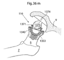
【選択図】図36mA medical device for implantation of a patient's hip joint is provided. The medical device comprises a first and second part and an adapted releasing member (first part of the first state holding attached to the second part) and the first part from the second part With state release immediately after joining. When the predetermined pressure is placed on the releasing member, the releasing member is adapted to change from the first state to the second state.
[Selection] Figure 36m
Description
本発明は、通常、股関節人工器官に関する。 The present invention generally relates to hip prostheses.
股関節骨関節炎は、軽度の炎症が股関節の痛みに結果としてなる症候群である、生じるによって股関節である場合中のクッションとして作用する軟骨を異常に着用する。
この軟骨も異常に着用することは、骨膜流体と呼ばれているジョイント潤滑流体の減少に結果としてなる。
股関節骨関節炎が、多少重大な形で、65歳以上の全ての人々の80%に影響を及ぼすことは、推定される。
Hip osteoarthritis is a syndrome in which mild inflammation results in hip pain, resulting in abnormal wearing of cartilage that acts as a cushion in the hip joint.
Abnormal wearing of this cartilage also results in a reduction in joint lubricating fluid called periosteal fluid.
It is estimated that hip osteoarthritis affects 80% of all people over the age of 65 in a somewhat more serious way.
腰骨関節炎の現在の治療は、股関節に油をさして、股関節の部を股関節手術による人工器官に置き換えることを助けるために、NSAID薬、ヒアルロン酸のローカル注入またはグルココルチコイドから成る。 Current treatment of hip osteoarthritis consists of NSAID drugs, local injections of hyaluronic acid or glucocorticoids to help oil the hip joint and replace the hip part with a hip prosthesis.
股関節の部を置き換えることは、毎年世界の何十万人もの患者で実行される日付まで最も一般の手術のある者である。
最も一般の方法は、大腿骨の金属人工器官を配置することと寛骨臼のプラスチック・ボウルとを具備している。この動作は、腰および上の大腿の切開によって、そして、大腿筋膜および大腿の横方向の筋肉によってされる。
股関節(カプセルが大腿骨に取り付けた、そして、骨盤のイリウムが突き通られるために必要である支持股関節)への接近を得るそれを作る手術の後、完全に機能ジョイントを得るために困難である。
大腿骨は、それから骨鋸を有する首で切られる、そして、人工器官は、骨を有するどちらでも結合する大腿骨に置かれる、または、寛骨臼はAcetabularリーマーを用いてわずかに拡大される、そして、プラスチック・ボウルはネジまたは骨セメントを用いて配置される。
Replacing the hip section is one of the most common surgeries to date performed in hundreds of thousands of patients worldwide every year.
The most common method involves placing a femoral metal prosthesis and an acetabular plastic bowl. This movement is done by an incision in the hip and upper thigh and by the femoral fascia and lateral muscles of the thigh.
After surgery to make it gain access to the hip joint (the supporting hip joint where the capsule is attached to the femur and iridium of the pelvis is penetrated) is difficult to obtain a fully functional joint .
The femur is then cut with a neck with a bone saw, and the prosthesis is placed on the femur that joins with either bone, or the acetabulum is slightly enlarged using an Acetable reamer, The plastic bowl is then placed using screws or bone cement.
腰の後の複雑化は、手術が大腿骨の骨のその固定からの人工器官の股関節およびゆるめることずれを含むことを接合する。人工器官のゆるむことおよび/またはずれは、例えば落下しているかまたは腰の迅速な動きを作っている患者から股関節に配置されている異常な圧力によって誘発されることができる。完全に固定股関節人工器官は順序を乱す可能性なしで大腿骨の骨のその固定からゆるんでいる人工器官の危険度を増す。これは、次のことの故である。全圧力はそれから大腿骨の骨に配置される。 The complication after the hip joins the surgery involves the hip and loosening displacement of the prosthesis from its fixation of the femoral bone. Prosthesis loosening and / or slipping can be induced, for example, by abnormal pressure placed on the hip joint from a patient who is falling or making a rapid movement of the hips. Fully fixed hip prostheses increase the risk of prosthesis loose from its fixation of the femoral bone without the possibility of out of order. This is because of the following. Total pressure is then placed on the femoral bone.
股関節手術の後、複雑化を減らすことができる股関節人工器官は、従って、望ましい。 A hip prosthesis that can reduce complications after hip surgery is therefore desirable.
患者の股関節の移植のための医療装置は、設けられている。医療装置には、固定するのに適している第1の部分が設けられて、骨盤ように構成されている。第1の部分に、凹接触表面に部分的に置かれるのに適している凸面接触表面が設けられている。
より深い医療装置には、固定するのに適している第二ピースが設けられて、大腿骨の骨ように構成されている。植設されるときに、第二ピースは部分的に前記第1の部分の凸面接触表面を囲むために適応する凹接触表面から成る。より深い医療装置は、第1の部分が第二ピースに取り付けた保持に適応する解除している部材(第1の状態の)を有し、第1のものは第二ピースから接合するすぐにステート解放を備えている。予め定められた圧力が解除している部材に配置されるときに、解除している部材は第1の状態から第2の状態に変化するために適応する。解除している部材を有する構造は、人体および補綴部との間に人体および/または相互接続のいかなる構造にも損害を与える危険を減らす。
A medical device for implantation of a patient's hip joint is provided. The medical device is configured as a pelvis with a first portion suitable for fixation. The first portion is provided with a convex contact surface suitable for being partially placed on the concave contact surface.
A deeper medical device is provided with a second piece that is suitable for fixation and is configured like a femur bone. When implanted, the second piece comprises a concave contact surface adapted to partially enclose the convex contact surface of the first part. The deeper medical device has a releasing member (in the first state) adapted to hold the first part attached to the second piece, the first one immediately joining from the second piece Has state release. When the predetermined pressure is placed on the releasing member, the releasing member is adapted to change from the first state to the second state. A structure having a releasing member reduces the risk of damaging any structure of the human body and / or the interconnection between the human body and the prosthesis.
医療装置の一実施例によれば、第1のおよび/または第2の部分の凸面接触表面は、少なくとも部分的に球形である。 According to one embodiment of the medical device, the convex contact surface of the first and / or second part is at least partly spherical.
他の実施例によれば、第二ピースの凹接触表面は、少なくとも部分的に球形である。 According to another embodiment, the concave contact surface of the second piece is at least partially spherical.
第1の部分は一実施例に従ってボール形の部分から成ることができる、そして、第二ピースはボウル形の部分から成ることができる。ボール形の部分は、機能している股関節を置き換えるためにボウル形の部分に置かれるために適応することができる。ボール形の部分は、解除している部材を用いているボウル形の部分において固定するために適応することができる。 The first part can consist of a ball-shaped part according to one embodiment, and the second piece can consist of a bowl-shaped part. The ball-shaped part can be adapted to be placed on the bowl-shaped part to replace a functioning hip joint. The ball-shaped part can be adapted for fixing in a bowl-shaped part using a releasing member.
本願明細書において実施例のいずれかによる解除している部材は非侵襲的に第2の状態に対する第1の状態から、そして、第2の状態から第1の状態に変化するために適応することができる。そのとき、予め定められた圧力は解除している部材に配置される。 The releasing member according to any of the embodiments herein is adapted to non-invasively change from the first state to the second state and from the second state to the first state. Can do. At that time, the predetermined pressure is arranged on the member being released.
第1および第2の部分の少なくとも1つに、部が医療装置が患者に植設されるときに、各々と接触してあるために適応させた少なくとも2が設けられている。 At least one of the first and second portions is provided with at least two portions adapted to be in contact with each other when the medical device is implanted in the patient.
他の実施例によれば、第1であるか前記第二ピースは、患者の骨盤の穴によって導入されるために適応する。少なくとも2つの部分が患者の骨盤の穴による股関節に導入されたあと、前記少なくとも2つの部分のある者は各々に機械的に固定するために適応することができる。 According to another embodiment, the first or second piece is adapted to be introduced by a hole in the patient's pelvis. After at least two parts have been introduced into the hip joint by a hole in the patient's pelvis, some of the at least two parts can be adapted for mechanical fixation to each other.
骨盤の穴は、530のmm2、380未満のmm2、250未満のmm2、180未満のmm2または110未満のmm2より小さい断面領域があることができる。 The pelvic hole can have a cross-sectional area less than 530 mm2, 380 mm2, less than 250 mm2, less than 180 mm2, or less than 110 mm2.
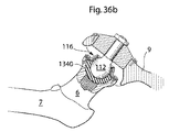
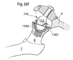
一実施例によれば、医療装置の第二ピースは、本願明細書において実施例のいずれかに従って、解除している部材から成る。解除している部材は弾力的な部分から成ることができる。そして、それは例えば弾性体、ばねまたは輪ゴムから成ることができる。バンドが部分的に少なくとも適応することができるゴムは、前記ボール形の部分を囲む。 According to one embodiment, the second piece of the medical device comprises a releasing member according to any of the embodiments herein. The releasing member can consist of a resilient part. It can for example consist of an elastic body, a spring or a rubber band. The rubber with which the band can be at least partially accommodated surrounds the ball-shaped part.
医療装置の他の実施例によれば、解除している部材は、少なくとも一つの屈曲可能な部分、可撓部分、圧縮可能な部分、可動部分または可動部から成る。 According to another embodiment of the medical device, the releasing member comprises at least one bendable part, a flexible part, a compressible part, a movable part or a movable part.
さらにもう一つの実施例によれば、解除している部材は、第1の部分を第二ピースに保持するために適応する磁石から成る。 According to yet another embodiment, the releasing member comprises a magnet adapted to hold the first part to the second piece.
さらにもう一つの実施例によれば、解除している部材は、予め定められた圧力で失敗するために適応する破裂装置から成る。破裂装置は、破裂バンドおよび/または破裂ピンから例えば成ることができる。 According to yet another embodiment, the releasing member comprises a rupture device adapted to fail at a predetermined pressure. The rupture device can for example consist of a rupture band and / or a rupture pin.
解除している部材一実施例に一致することが、複数の保持把手(第1の部分に対して摺動するために次々に適応することができる)を成ることができてまたは第1の部分に対して転がることができる。保持把手が転がるために適応させた一実施例に一致することに、ボール形の保持把手が設けられている。 According to one embodiment of the releasing member, it can consist of a plurality of holding handles (which can be adapted one after the other to slide relative to the first part) or the first part Can roll against. In accordance with one embodiment adapted for rolling of the holding handle, a ball-shaped holding handle is provided.
医療装置が患者に植設されるときに、本願明細書において実施例のいかなるある者にもよる医療装置の第1の部分は各々と接触してあるために適応する少なくとも2つの部から成ることができる。少なくとも2つの部が患者の骨盤の穴による股関節に導入されたあと、少なくとも2つの部のある者は少なくとも2つの部の第2まで機械的に固定するために適応することができる。 When the medical device is implanted in a patient, the first part of the medical device according to any one of the embodiments herein comprises at least two parts adapted to be in contact with each other Can do. After at least two parts have been introduced into the hip joint by a hole in the patient's pelvis, a person with at least two parts can be adapted to mechanically secure up to the second of the at least two parts.
部分が一実施例に従ってそうすることができる第一は、医療装置が骨盤(少なくとも一つの方向で初めての部分の圧縮を可能にしている弾力的な部分)の穴で嵌入されることを可能にするために適応する可撓部分または弾力的な部分から成る。 The first that the part can do according to one embodiment allows the medical device to be inserted with a hole in the pelvis (the elastic part allowing the compression of the part for the first time in at least one direction) It consists of a flexible part or an elastic part adapted to do.
さらにもう一つの実施例によれば、第1の部分は、第1の領域および第二領域から成る。第1の領域にはゴムであるのに適している第1の素材が設けられ、第二領域にはゴムであるのに適している第2の素材が設けられている。第1の素材は、第2の素材より弾力的であるために適応することができる。 According to yet another embodiment, the first portion comprises a first region and a second region. A first material suitable for being rubber is provided in the first region, and a second material suitable for being rubber is provided in the second region. The first material can be adapted to be more elastic than the second material.
医療装置が患者に植設されるときに、医療装置の一実施例によれば、第二ピースは各々と接触してあるために適応する少なくとも2つの部から成る。少なくとも2つの部が患者の骨盤の穴による股関節に導入されたあと、少なくとも2つの部のある者は少なくとも2つの部の1秒まで機械的に固定するために適応することができる。 When the medical device is implanted in a patient, according to one embodiment of the medical device, the second piece consists of at least two parts adapted to be in contact with each other. After at least two parts have been introduced into the hip joint by a hole in the patient's pelvis, one with at least two parts can be adapted to mechanically secure at least two parts up to 1 second.
装置がさらにもう一つの実施例に従ってそうすることができる健康診断は、解除している部材が前記第2の状態に初めての状態から変化することを必要とする予め定められた圧力を調整するための較正部材から成る。較正部材は、較正ネジでありえた。 A health check that the device can do according to yet another embodiment is to adjust a predetermined pressure that requires the releasing member to change from the initial state to the second state. The calibration member. The calibration member could be a calibration screw.
本願明細書において実施例のいずれかに従って医療装置を取り付ける方法は、更に設けられている。方法に、次のステップが設けられている。外科的であるか関節鏡の手順による股関節を露出させて、骨盤に医療装置の第1の部分を固定させて、大腿骨の骨に医療装置の第二ピースを固定させて、第二ピースと関連して第1の部分を配置して、第1の部分を解除している部材を用いている第二ピースに保持すること。 There is further provided a method of attaching a medical device according to any of the embodiments herein. The method includes the following steps. Exposing the hip joint by a surgical or arthroscopic procedure, fixing the first part of the medical device to the pelvis, and fixing the second piece of the medical device to the bone of the femur; Relatedly, placing the first part and holding it in the second piece using the member releasing the first part.
一実施例によれば、第1の部分を解除している部材を用いている第二ピースに保持するステップは、第1の部分を弾性部材を用いている第二ピースに保持することから成る。
さらにもう一つの実施例によれば、第1の部分を弾性部材を用いている第二ピースに保持するステップは、第1の部分を輪ゴムを用いている第二ピースに保持することから成る。
According to one embodiment, the step of holding the first part on the second piece using the releasing member comprises holding the first part on the second piece using the elastic member. .
According to yet another embodiment, the step of holding the first part on the second piece using the elastic member comprises holding the first part on the second piece using the rubber band.
一実施例によれば、第1の部分を解除している部材を用いている第二ピースに保持するステップは、第1の部分を破裂している部材を用いている第二ピースに保持することから成ることができる。破裂している部材は、破裂しているバンドでありえた。 According to one embodiment, the step of holding the first part on the second piece using the releasing member holds the first part on the second piece using the rupturing member. Can consist of. The rupturing member could be a rupturing band.
他の実施例によれば、第1の部分を第二ピースに保持するステップは、第1の部分をバネ・ロードした部材を用いている第二ピースに保持することから成る。 According to another embodiment, the step of holding the first part on the second piece consists of holding the first part on the second piece using a spring loaded member.
患者の股関節の移植のための医療装置は、更に設けられている。医療装置は、第1および第2の部分および適応する解除している部材(第1の部分が第二ピースに取り付けた第1のステート保持の)と第1のものは第二ピースから接合するすぐにステート解放とを具備している。予め定められた圧力が解除している部材に配置されるときに、解除している部材は第1の状態から第2の状態に変化するために適応する。 A medical device for implantation of the patient's hip joint is further provided. The medical device joins the first and second parts and the corresponding releasing member (the first part holding the first state attached to the second piece) and the first from the second piece. With state release immediately. When the predetermined pressure is placed on the releasing member, the releasing member is adapted to change from the first state to the second state.
一実施例によれば、第1の部分はボール形の部分から成る。そして、少なくとも股関節の頭大腿骨の表層を置き換えるために適応する。 According to one embodiment, the first part comprises a ball-shaped part. And it is adapted to replace at least the surface of the hip and femur of the hip joint.
一実施例によれば、第二ピースはボウル形の部分から成る。そして、少なくとも股関節の寛骨臼面を置き換えるために適応する。 According to one embodiment, the second piece consists of a bowl-shaped part. And adapted to replace at least the acetabular surface of the hip joint.
他の実施例によれば、第1の部分はボール形の部分から成る、そして、第二ピースはボウル形の部分から成る、そして、ボール形の部分は機能している股関節を置き換えるためにボウル形の部分に置かれるために適応する。それによって、完全に人工股関節をつくる。ボール形の部分は、解除している部材を用いているボウル形の部分において固定するために適応することができる。 According to another embodiment, the first part consists of a ball-shaped part, the second piece consists of a bowl-shaped part, and the ball-shaped part is a bowl to replace the functioning hip joint Adapt to be placed on a piece of shape. As a result, a total hip joint is created. The ball-shaped part can be adapted for fixing in a bowl-shaped part using a releasing member.
実施例のいずれかによる解除している部材は非侵襲的に第2の状態に対する第1の状態から、そして、第2の状態から第1の状態に変化するために適応することができる。そのとき、予め定められた圧力は前記解除している部材に配置される。このことにより、順序を乱される場合、股関節は外科的手技を必要とせずに復帰することができる。 The releasing member according to any of the embodiments can be adapted to change non-invasively from the first state to the second state and from the second state to the first state. At that time, a predetermined pressure is arranged on the released member. This allows the hip joint to return without requiring a surgical procedure if out of order.
医療装置が患者に植設されるときに、第1および第2の部分で少なくとも一つのものは各々と接触してあるために適応する少なくとも2つの部から成ることができる。 When the medical device is implanted in a patient, at least one of the first and second portions can comprise at least two portions adapted to be in contact with each other.
第一および/または第二ピースは、患者の骨盤の穴によって導入されるために適応することができる。 The first and / or second piece can be adapted to be introduced by a hole in the patient's pelvis.
少なくとも2つの部分が患者の骨盤の穴による股関節に導入されたあと、一実施例によれば、少なくとも2つの部分は各々に機械的に固定するために適応する。 After at least two parts have been introduced into the hip joint by a hole in the patient's pelvis, according to one embodiment, the at least two parts are adapted for mechanical fixation to each other.
部材を解除すること Releasing a member
一実施例によれば、医療装置の第1の部分は、解除している部材から成る。いずれが、解除している部材から成っている医療装置のボール形の部分でありえたか。他の実施例に医療装置の第二ピースを一致させることに、解除している部材が設けられている。いずれが、解除している部材から成っている医療装置のボウル形の部分でありえたか。 According to one embodiment, the first part of the medical device consists of a releasing member. Which could be the ball-shaped part of the medical device made of the releasing member? A release member is provided for aligning the second piece of the medical device with another embodiment. Which could be a bowl-shaped part of a medical device made of a releasing member?
他の実施例によれば、解除している部材は弾力的な部分から成る。そして、それは次々に弾性体から成ることができる。 According to another embodiment, the releasing member consists of a resilient part. And it can consist of elastic bodies one after another.
さらにもう一つの実施例によれば、解除している部材は、屈曲可能なおよび/または柔軟なおよび/または圧縮可能な部分から成る。解除している部材が可動部分または可動部から成ることは、さらに、考えられる。 According to yet another embodiment, the releasing member consists of a bendable and / or flexible and / or compressible part. It is further conceivable that the releasing member consists of a movable part or a movable part.
医療装置が弾力的な部分から成る実施例において、弾力的な部分がばねおよび/または輪ゴムから成ることができること、部分的に少なくとも適応することがありえたボール形の部分を囲む、そして、このことにより、ボールを保つことはボウル形の部分の部分を形づくった。輪ゴムは、ボール形の部分およびボウル形の部分の間に配置されるために、更に適応することができる。 In an embodiment in which the medical device consists of a resilient part, the resilient part can consist of a spring and / or a rubber band, partially encloses a ball-shaped part that could be adapted and this By keeping the ball shaped part of the bowl-shaped part. The rubber band can be further adapted to be placed between the ball-shaped part and the bowl-shaped part.
さらにもう一つの実施例によれば、解除している部材は、第1の部分を第二ピースに保持するために適応する磁石から成る。 According to yet another embodiment, the releasing member comprises a magnet adapted to hold the first part to the second piece.
他の実施例によれば、第二ピースから第1の部分を解除するために、解除している部材は、予め定められた圧力で失敗するために適応する破裂装置から成る。破裂装置は破裂バンドから成ることができる、部分的に少なくとも適応することがありえたボール形の部分を囲む。破裂バンドは、一実施例に従ってボール形の部分およびボウル形の部分の間に配置されることができて、破裂ピンから成ることができる。 According to another embodiment, in order to release the first part from the second piece, the releasing member comprises a rupture device adapted to fail at a predetermined pressure. The rupture device encloses a ball-shaped part that may consist of a rupture band, which may be at least partially adaptable. The rupture band can be disposed between the ball-shaped portion and the bowl-shaped portion according to one embodiment, and can comprise a rupture pin.
解除している部材は複数の保持把手から成ることができる、そして、保持把手または保持把手は前記第1の部分に対して摺動するために適応することができておよび/または前記第1の部分に対して転がるために適応することができる。保持把手は、ボール形の保持把手から成ることができる。 The releasing member can comprise a plurality of holding handles, and the holding handles or holding handles can be adapted to slide relative to the first portion and / or the first Can adapt to roll against part. The holding handle can comprise a ball-shaped holding handle.
第1の部分 First part
一実施例によれば、医療装置が患者に植設されるときに、第1の部分は各々と接触してあるために適応する少なくとも2つの部から成る。 According to one embodiment, when the medical device is implanted in a patient, the first part comprises at least two parts adapted to be in contact with each other.
第1の部分は、実施例のいずれかに従って、患者の骨盤の穴によって導入されるために適応することができる。 The first part can be adapted to be introduced by a hole in the patient's pelvis according to any of the embodiments.
一実施例によれば、少なくとも2つの部が患者の骨盤の穴による股関節に導入されたあと、少なくとも2つの部のある者は少なくとも2つの部の第2まで機械的に固定するために適応する。 According to one embodiment, after at least two parts have been introduced into the hip joint by a hole in the patient's pelvis, a person with at least two parts is adapted to mechanically secure to a second of the at least two parts .
第1の部分は、医療装置が骨盤の穴によって嵌入されることを可能にするために適応する可撓部分および/または弾力的な部分から成ることができる。弾力的な部分は、少なくとも一つの方向の第1の部分の圧縮を可能にすることができる。 The first part may consist of a flexible part and / or a resilient part adapted to allow the medical device to be inserted by a pelvic hole. The resilient portion can allow compression of the first portion in at least one direction.
第1の部分は第1の領域および第二領域から成ることができる、第1の領域は弾力的であるために適応する第1の素材から成ることができる、そして、第二領域は弾力的であるために適応する第2の素材から成ることができる、そして、第1の素材は第2の素材より弾力的であるために適応することができる。 The first portion can consist of a first region and a second region, the first region can consist of a first material adapted to be elastic, and the second region is elastic It can consist of a second material that adapts to be, and the first material can adapt to be more elastic than the second material.
第二ピース Second piece
医療装置が患者に植設されるときに、一実施例によれば、第二ピースは各々と接触してあるために適応する少なくとも2つの部から成る。第二ピースは、患者の骨盤の穴によって導入されるために適応することができる。 When the medical device is implanted in a patient, according to one embodiment, the second piece consists of at least two parts adapted to be in contact with each other. The second piece can be adapted to be introduced by a hole in the patient's pelvis.
他の実施例によれば、少なくとも2つの部が患者の骨盤の穴による股関節に導入されたあと、前記少なくとも2つの部のある者は少なくとも2つの部の1秒まで機械的に固定するために適応することができる。 According to another embodiment, after at least two parts have been introduced into a hip joint by a hole in the patient's pelvis, a person with the at least two parts can mechanically secure at least two parts up to 1 second. Can adapt.
医療装置が少なくとも三次元的にカーブする股関節面から成るさらにもう一つの実施例によって、
内面および外面。
内面に、6つの異なる位置が設けられている。
第1の位置、第2の位置、第3の位置、第4の位置、第5の位置および第6の位置(内面の長さ軸に沿った異なる場所にある全ての位置)。
前記第1の位置から位置が前記第3の位置から前記第4の位置まで第2の直線と平行して達している前記2番まで手を伸ばして、最初の直線、それは、次々に、前記第5の位置から前記第6の位置まで手を伸ばしている3本目の直線と平行である。
さらにまた、第1で3本目の直線は前記第2の直線より短い、そして、前記第2の直線は前記第1で前記3本目の直線の間に位置する。
According to yet another embodiment, wherein the medical device comprises a hip joint surface that curves at least three-dimensionally,
Inside and outside.
There are six different positions on the inner surface.
1st position, 2nd position, 3rd position, 4th position, 5th position, and 6th position (all positions at different locations along the length axis of the inner surface).
Reaching up to the second position where the position from the first position reaches the second position from the third position to the fourth position in parallel with the second straight line, the first straight line, which in turn, It is parallel to the third straight line reaching from the fifth position to the sixth position.
Furthermore, the first and third straight lines are shorter than the second straight line, and the second straight line is located between the first and third straight lines.
医療装置は、前記解除している部材が前記第1の状態から前記第2の状態に変化することを必要とする予め定められた圧力を調整するための較正部材から更に成ることができる。較正部材は、較正ネジでありえた。 The medical device can further comprise a calibration member for adjusting a predetermined pressure that requires the releasing member to change from the first state to the second state. The calibration member could be a calibration screw.
通常の股関節は、頭大腿骨に至っている軸配分を有する、結腸煙突大腿骨がある、実質的に、ボールは前記結腸煙突大腿骨の前記軸配分の延長の中心の軸と実質的に直角をなす最大直径を有する構成を成形した。
頭大腿骨は、股関節をつくっているボウル形の寛骨臼に置かれる。
ボウル形の寛骨臼は、開口部および寛骨臼ボウルの一番下の中心からの中心の軸および、開口部の方のボウルの中央および頭大腿骨後の、そこにおいて、寛骨臼を有する第2の軸配分に寛骨臼の第2の軸配分の中心の軸と実質的に直角をなす最大直径を有させる。
軸配分の中心の軸の延長は第2の軸配分の中心の軸と同一である。そのとき、頭大腿骨は寛骨臼ボウルの中央に置かれて対称形のポジションにおいてある。
医療装置は、二つ人工股関節面(部分が成る第一)から成る;
人工股関節は成ることに表面をつける、表層が部分的に少なくとも適応させた人工頭大腿骨は置き換える、そして、結腸煙突大腿骨の反対側に、そして、適応して、頭大腿骨の共同の表層を置き換えて、ジョイントに取り付けられるときに、従って、寛骨臼ボウルまたは人工の置換に置かれる。
カバーするために適応する表層の部を越えて最初に少なくともある者から成っておよび/または前記頭大腿骨の最大直径を越えて少なくとも前記頭大腿骨の部上の前記頭大腿骨の骨に入って、ジョイントのその機能的なポジションの前記頭大腿骨に載置するときに前記結腸煙突大腿骨の方の前記寛骨臼ボウルから間隔をおいて配置されて、人工の頭大腿骨面。
部を越えた少なくとも一つの第一は、前記頭大腿骨の前記最大直径の周辺および前記中心の軸の間の距離より小さくて、前記中心の軸までの最も近い垂直な距離を有するために適応するこのように適応させる作成する、そして、前記機能的なポジションの前記頭大腿骨に載置するときに、前記人工の頭大腿骨面のより安定ポジションを作成する。
を越えて、部は、少なくとも解除している部材の部から成る。
The normal hip joint has a colon chimney femur with an axial distribution leading to the cranial femur, substantially the ball is substantially perpendicular to the central axis of the extension of the axial distribution of the colon chimney femur. A configuration having the largest diameter was formed.
The craniofemur is placed in a bowl-shaped acetabulum creating a hip joint.
A bowl-shaped acetabulum is a central axis from the bottom center of the opening and acetabulum bowl and the center of the bowl towards the opening and the posterior femoral bone, where The second axial distribution having has a maximum diameter substantially perpendicular to the central axis of the second axial distribution of the acetabulum.
The extension of the central axis of the axial distribution is the same as the central axis of the second axial distribution. The craniofemur is then placed in the center of the acetabular bowl and in a symmetrical position.
The medical device consists of two artificial hip joint surfaces (part 1);
The hip prosthesis is surfaced, the surface is partially adapted to replace at least the artificial head femur, and on the opposite side of the colon chimney femur and adapted to the joint surface of the head and femur And when placed in the joint, therefore placed in an acetabular bowl or artificial replacement.
Firstly composed of at least one person beyond the superficial part adapted to cover and / or enters the craniofemoral bone on at least the craniofemoral part beyond the maximum diameter of the craniofemur An artificial craniofemoral surface spaced from the acetabular bowl towards the colon chimney femur when mounted on the craniofemur in its functional position of the joint.
At least one first beyond the portion is adapted to have a closest vertical distance to the central axis that is less than the distance between the circumference of the maximum diameter of the craniofemur and the central axis Create a more stable position of the artificial craniofemoral surface when mounted on the craniofemur in the functional position.
Beyond this, the part comprises at least the part of the member that has been released.
通常の腰は軸配分を有する結腸煙突大腿骨を有することを頭大腿骨に導くようにする。そして、実質的に、ボールは前記結腸煙突大腿骨の前記軸配分の延長の中心の軸と実質的に直角をなす最大直径を有する構成を成形した。
頭大腿骨は、股関節をつくっているボウル形の寛骨臼に置かれる。
ボウル形の寛骨臼は、前記寛骨臼ボウルの一番下の中心から、そして、開口部の方の前記ボウルの中央および頭大腿骨後の開口部および中心の軸を有する第2の軸配分を有する。
寛骨臼は寛骨臼の前記第2の軸配分の中心の軸と実質的に直角をなす最大直径を有する、軸配分の中心の軸の延長は第2の軸配分の中心の軸と同一である。そのとき、頭大腿骨は寛骨臼ボウルの中央に置かれて対称形のポジションにおいてある。
医療装置は二つ人工股関節面から成る、人工股関節は成ることに表面をつける、表層が部分的に少なくとも適応させた人工寛骨臼は置き換える、そして、ジョイントを交換することは寛骨臼の中で浮上して、股関節に取り付けられるときに、頭大腿骨または従って、人工の置換上に配置されるために適応させた。
股関節のその機能的なポジションで、従って、頭大腿骨または人工代わりに載置するときに、人工の寛骨臼面は寛骨臼(結腸煙突大腿骨の方の寛骨臼ボウルから間隔をおいて配置される)の最大直径を越えて従って、少なくとも頭大腿骨または人工代わりの部をカバーするために適応する表層の部を越えて最初に少なくともある者から成る。
前記人工の寛骨臼面の前記最大直径の周辺および前記中心の軸の間の距離より小さくて、前記中心の軸までの最も近い垂直な距離を有するために適応する部を越えて最初に少なくとも一つであるこのように適応させる作成する、そして、頭大腿骨または従って、前記股関節の前記機能的なポジションにおいて、人工の置換に載置するときに、人工の寛骨臼面のより安定ポジションを作成する。
部を越えて第1であるものに、解除している部材が設けられている。
The normal waist will guide the craniofemur to have a colon chimney femur with an axial distribution. And substantially the ball was shaped to have a maximum diameter substantially perpendicular to the central axis of the extension of the axial distribution of the colon chimney femur.
The craniofemur is placed in a bowl-shaped acetabulum creating a hip joint.
A bowl-shaped acetabulum is a second axis having a central axis of the bowl from the bottom center of the acetabular bowl and the opening and central axis of the posterior and femoral bone toward the opening. Have a distribution.
The acetabulum has a maximum diameter substantially perpendicular to the central axis of the second axial distribution of the acetabulum, and the extension of the central axis of the axial distribution is the same as the central axis of the second axial distribution It is. The craniofemur is then placed in the center of the acetabular bowl and in a symmetrical position.
The medical device consists of two prosthetic hip surfaces, the hip prosthesis is made to surface, the surface layer is at least partially adapted to replace the artificial acetabulum, and the replacement of the joint is in the acetabulum And was adapted to be placed over the craniofemur or hence artificial replacement when attached to the hip joint.
In its functional position at the hip joint, therefore, when placed in place of the craniofemur or prosthesis, the artificial acetabulum surface is spaced from the acetabulum (the acetabulum bowl towards the colon chimney femur). Therefore, it is initially composed of at least one person beyond the superficial part adapted to cover at least the head femur or artificial substitute part.
Less than the distance between the circumference of the maximum diameter of the artificial acetabulum surface and the central axis, and first at least beyond the portion adapted to have the closest vertical distance to the central axis This is one more adaptable creation and more stable position of the artificial acetabulum surface when placed in an artificial replacement in the functional position of the head femur or hence the hip joint Create
The first member beyond the part is provided with a releasing member.
第二ピースから第1の部分を解除することを可能にするために、解除している部材は、実施例のいずれかに従って、弾力的な部分および/または屈曲可能な部分および/または可撓部分および/または圧縮可能な部分および/または可動部分および/または可動部から成ることができる。 In order to be able to release the first part from the second piece, the releasing member may be a resilient part and / or a bendable part and / or a flexible part according to any of the embodiments And / or can consist of a compressible part and / or a movable part and / or a movable part.
実施例のいずれかに一致することが更にそうである医療装置を取り付ける方法は定めた、方法は次のステップから成る
外科的であるか関節鏡の手順による股関節を露出させて、大腿骨の骨に前記医療装置の前記第1の部分を固定させて、骨盤に前記医療装置の前記第二ピースを固定させて、前記第二ピースと関連して前記第1の部分を配置して、前記第1の部分を前記解除している部材を用いている前記第二ピースに保持すること。
A method of attaching a medical device that is more likely to correspond to any of the embodiments defined, the method comprises the following steps: exposing the hip joint by a surgical or arthroscopic procedure to expose the femoral bone Fixing the first part of the medical device, fixing the second piece of the medical device to the pelvis, and arranging the first part in relation to the second piece, 1 part is hold | maintained in said 2nd piece using the member which has cancel | released.
一実施例によれば、第1の部分を第二ピースに保持するステップは、第1の部分を弾性部材を用いている第二ピースに保持することから成る。 According to one embodiment, the step of holding the first part on the second piece consists of holding the first part on the second piece using an elastic member.
一実施例によれば、第1の部分を第二ピースに保持するステップは、第1の部分を破裂している部材を用いている第二ピースに保持することから成る。 According to one embodiment, the step of holding the first part on the second piece consists of holding the first part on the second piece using a rupturing member.
一実施例によれば、第1の部分を第二ピースに保持するステップは、第1の部分をバネ・ロードした部材を用いている第二ピースに保持することから成る。 According to one embodiment, the step of holding the first part on the second piece consists of holding the first part on the second piece using a spring loaded member.
一実施例によれば、第1の部分を第二ピースに保持するステップは、第1の部分を輪ゴムを用いている第二ピースに保持することから成る。 According to one embodiment, the step of holding the first part on the second piece consists of holding the first part on the second piece using rubber bands.
一実施例によれば、第1の部分を第二ピースに保持するステップは、第1の部分を破裂しているバンドを用いている第二ピースに保持することから成る。 According to one embodiment, the step of holding the first part on the second piece consists of holding the first part on the second piece using a rupturing band.
いかなる実施例または実施例、特徴、方法の部がシステムを結びつけた点に注意します、本願明細書において記載されているシステムの、または、付随する数字の部は、いかなる形であれ結合されるかもしれない。 Note that any embodiment or embodiment, feature, or method portion associated with the system, any number portion of the system or accompanying numbers described herein may be combined in any way. It may be.
本発明は、現在記載されている、添付の図面に関して、例証として:
弾力は、弾力的な方法で変形する素材能力として理解されることになっている。 Elasticity is to be understood as the ability of a material to deform in an elastic way.
弾力的な変形は、素材が応力(例えば外部の力)の下で変形する時であるが、応力が除去されるときに、その最初の形状に戻る。より弾性素材は、弾力の低い率を有する素材として理解されることになっている。物体の弾力的な率は、弾力的な変形領域のその応力‐歪み曲線の傾斜として定義される。弾力的な率は応力/圧力として算出される。ここで、応力は変形が生じている力である。そして、力が適用される領域によって分けられる;
そして、圧力は、応力によって生じる変化の比率である。
Elastic deformation is when the material deforms under stress (eg, external force), but returns to its original shape when the stress is removed. More elastic materials are to be understood as materials having a low rate of elasticity. The elastic rate of an object is defined as the slope of its stress-strain curve in the elastic deformation region. The elastic rate is calculated as stress / pressure. Here, the stress is a force causing deformation. And divided by the area where the force is applied;
The pressure is the rate of change caused by stress.
剛性は、適用された力による変形に対する弾性体の抵抗として理解されることになっている。 Stiffness is to be understood as the resistance of an elastic body to deformation by an applied force.
機能的な腰運動は、少なくとも部分的に腰の自然な動きに対応する腰の動きとして理解されることになっている。若干の場合に、股関節の自然な動きはいくらか制限されるかもしれないかまたは股関節手術の後、変えられるかもしれない。そして、それは自然の股関節の機能的な腰動きとはいくらか異なる人工の表層を有する股関節の機能的な腰動きを作る。 Functional hip movements are to be understood as hip movements that at least partially correspond to the natural movements of the hips. In some cases, the natural movement of the hip joint may be somewhat restricted or changed after hip surgery. And it creates a functional hip movement of the hip joint with an artificial surface that is somewhat different from the functional hip movement of the natural hip joint.
移植可能医療装置または人工器官の機能的なポジションは、股関節が機能的な腰運動を実行することができるポジションである。最終的なポジションは、医療装置がより深いポジション変化を必要としない機能的なポジションとして理解されることになっている。 A functional position of an implantable medical device or prosthesis is a position where the hip joint can perform a functional waist movement. The final position is to be understood as a functional position where the medical device does not require deeper position changes.
生体親和性材料は、免疫反応の低レベルを有する素材であるとして理解されることになっている。生体親和性材料は、時々生体適合物質と呼ばれもする。類似している生物学的適合性の金属である低い免疫反応(例えばチタンまたはタンタル)によって生物学的適合性の金属。生物学的適合性の金属は、少なくとも一つの生物学的適合性の金属から成っている生物学的適合性の合金でもありえた。 A biocompatible material is to be understood as a material having a low level of immune response. Biocompatible materials are sometimes referred to as biocompatible materials. A biocompatible metal with a low immune response (eg titanium or tantalum) that is a similar biocompatible metal. The biocompatible metal could also be a biocompatible alloy made of at least one biocompatible metal.
形部品は、部を有している要素または前記部または断面を用いている少なくとも一つの他の要素に前記要素の機械的接続を可能にするために適応する断面として理解されることになっている。調子適した構造は、形部品を使用可能にする要素の構造である。 A shaped part is to be understood as a cross section adapted to allow mechanical connection of said element to an element having a part or at least one other element using said part or cross section. Yes. A suitable structure is the structure of the element that enables the shaped part to be used.
実施例のいずれかによる医療装置は、少なくとも、素材が成ることをグループから選択したある者から成ることができる:
ポリテトラフルオロエチレン(PTFE)過フルオロ・アルコキシ(PFA)でフッ化エチレン・プロピレン(FEP)。
素材が金属合金(例えばコバルト−クロミウム−モリブデンまたはチタンまたはステンレス鋼)から成ることはさらに、考えられる、または、ポリエチレン、例えばクロスリンク・ポリエチレンまたはガスはポリエチレンを殺菌した。
接触表面または全ての医療装置(例えばジルコニウムまたは二酸化ジルコニウム・セラミックまたはアルミナ・セラミック)で、セラミック材料の使用は、考えられもする。
人体の骨に対する医療装置の固定のための人体の骨と接触する医療装置の部は、医療装置を固定させるための医療装置の人体の骨のgrowth−inを促進するために適応する多孔性マイクロまたはナノ構造でありえた救貧院構造から成ることができる。
多孔質構造体はヒドロキシアパタイト(HA)コーティングまたは粗くopen−poredされたチタン・コーティング(空気プラズマ噴霧によってできることができる)を適用することにより提供されることができる。そして、ラフから成っている組合せはチタン・コーティングをopen−poredした、そして、HA表層は考えられもする。
接触部は蝋様変性のポリマー(例えばPTFE、PFA、FEP、PEおよびUHMWPE)のような自己油をさされた素材または潤滑油を吹き込まれることができる粉末冶金素材でできていることがありえた。そして、それは好ましくは生物学的適合性の潤滑油(例えばHyaluronic酸派生物)である。
本願明細書において医療装置の部または表層を接触させる素材が常に、または、断続的に油をさされるために適応することは、考えられもする。
若干の実施例によれば、医療装置の部または部分は、金属素材および/または炭素繊維および/またはホウ素の組合せ、金属およびプラスチック材料の組合せ、金属およびカーボンを主成分とする素材の組合せ、カーボンおよびプラスチックを主成分とする素材の組合せ、可撓性で固い素材の組合せ、弾性でより少ない弾性体の組合せ、Corianまたはアクリル系ポリマから成ることができる。
A medical device according to any of the embodiments can comprise at least one person who has selected from the group that the material is made of:
Polytetrafluoroethylene (PTFE) perfluoroalkoxy (PFA) and fluorinated ethylene propylene (FEP).
It is further conceivable that the material consists of a metal alloy (for example cobalt-chromium-molybdenum or titanium or stainless steel) or polyethylene, for example cross-linked polyethylene or gas, has sterilized the polyethylene.
The use of ceramic materials on the contact surface or on all medical devices (eg zirconium or zirconium dioxide ceramic or alumina ceramic) is also conceivable.
The portion of the medical device in contact with the bone of the human body for fixation of the medical device to the bone of the human body is adapted to promote the growth-in of the human bone of the medical device for fixing the medical device. Or it can consist of a poverty structure that could be nanostructured.
The porous structure can be provided by applying a hydroxyapatite (HA) coating or a coarsely open-poored titanium coating (which can be done by air plasma spraying). And the combination consisting of a rough-opened-poored titanium coating and the HA surface layer is also conceivable.
The contact could be made of a self-oiled material such as a waxy modified polymer (eg PTFE, PFA, FEP, PE and UHMWPE) or a powder metallurgy material that can be infused with a lubricating oil. . And it is preferably a biocompatible lubricating oil (eg Hyaluronic acid derivative).
It is also conceivable here that the material that contacts the part or surface of the medical device is adapted to be constantly or intermittently oiled.
According to some embodiments, the medical device part or part comprises a metal material and / or a combination of carbon fiber and / or boron, a combination of metal and plastic material, a combination of metal and carbon-based material, carbon And a combination of materials based on plastic, a combination of flexible and hard materials, a combination of elastic and less elastic bodies, Corian or acrylic polymers.
以下において、本発明の好ましい実施例の詳細な説明は、与えられる。
図面において、参照番号の様に、数桁の全体にわたって同一であるか対応する要素を示す。これらの図が例示目的のためにあって、本発明の範囲をいかなる形であれ制限していないことはいうまでもない。このように、方向のいかなる参照も、例えば「上へ」または、「下って」図に示される方向に関連しているだけである。また、いかなる寸法もなど。図において、目的は、説明のために示される。
In the following, a detailed description of a preferred embodiment of the present invention is given.
In the drawings, like reference numerals indicate elements that are the same or corresponding throughout a few digits. It will be appreciated that these figures are for illustrative purposes and do not limit the scope of the invention in any way. Thus, any reference to a direction is only related to the direction shown in the figure, for example, “up” or “down”. Also any dimensions etc. In the figure, the purpose is shown for explanation.
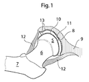
図1は、断面のヒト患者の股関節を示す。
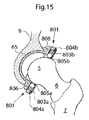
股関節に、頭大腿骨5(または人工代わり従って)大腿骨の骨7の最上部である結腸煙突大腿骨6のまさしくその表面に配置されるてが設けられている。頭大腿骨5は、骨盤9のボウル形の部である寛骨臼8と関連してある。頭大腿骨面10および表層11がそうである寛骨臼は、股関節のクッションとして作用する関節軟骨13によってカバーした。
股関節骨関節炎患者において、この関節軟骨13は、軽度の炎症により異常に摺り減らされる。股関節は、サポートをジョイントに提供して、脱臼を遅らせる股関節カプセル12によって囲まれる。従来の股関節手術の後、股関節カプセル12を突き通って、カプセル12は、その靭帯組織の限られた治癒可能性のため、劇的に弱められる。股関節カプセル12に損害を与えることのない股関節手術を実行することによって、自然なある者に可能であるように、患者は完全に回復することができて、圧力の等しい量を人工関節に配置することができる。
FIG. 1 shows a hip joint of a human patient in cross section.
The hip joint is provided with a spatula placed on the very surface of the
In patients with hip osteoarthritis, the
図2は、切開112が外科医は頭大腿骨5が位置する大腿骨の骨7に達することができている大腿113において作られる従来の股関節手術の側面図を示す。大腿骨の骨7はそれから、頭大腿骨5を露出させている股関節カプセル12から引き抜かれる。そして、それは交換されるかまたは動作の間、浮上した。
FIG. 2 shows a side view of a conventional hip surgery in which an
図3は、人工の頭大腿骨面45を従来の手術の頭大腿骨5に配置することを示す。しかしながら最高水準の技術の他の実施例によれば、全ての結腸煙突大腿骨6は骨鋸を用いて取り出される。そして、それの後、頭大腿骨から成っている補綴部は大腿骨の骨を用いている骨セメントまたは機械式固定している部材において固定する。股関節がその機能的なポジションの機能的な腰運動を実行するときに、ボウル形のカップはそれから、新しい人工頭大腿骨45に対する接触表面として作用するために寛骨臼8に置かれる。従来技術、人工の頭大腿骨面および人工寛骨臼によれば、表層は股関節カプセルによって一緒に保たれている。そして、カプセルが動作の間、突き通られるときに、それは劇的に弱められる。
FIG. 3 shows the placement of an artificial craniofemoral surface 45 on a conventional
次に、股関節を操作する選択肢方法について説明する。 Next, an option method for operating the hip joint will be described.
図4は、ヒト患者の身体の正面の図を示す。股関節を操作する腹腔鏡/関節鏡の方法は、寛骨臼からの反対側から、ヒト患者の腹壁の小さい切開14を作ることから始めて実行される第1実施例に一致している。小さい切開で、外科医は腹腔鏡トロカールをヒト患者の腹部に嵌入することができる。第1実施例に切開14を一致させることは、人体の特許の腹部に、腹直筋および腹膜を中で通過する。腹膜の下で、第2の好ましい実施例に小さい切開15を一致させることは、骨盤領域に、腹直筋で、そして、中で実行される。第三実施態様に小さい切開16を一致させることは、イリウムおよび周囲組織(骨盤が筋膜および筋組織のごくわずかな浸透にしかよって切開されないことを可能にすることができる切開16)との間に正当で実行される。第四実施態様によれば、切開17は、鼠蹊部チャネルにおいて作られる。4つの実施例の全てにおいて寛骨臼8の反対側に領域の骨盤9を囲んでいる組織が取り出されるかまたは突き通られること、外科医は骨盤9に達することができる。
FIG. 4 shows a front view of the human patient's body. The laparoscopic / arthroscopic method of manipulating the hip joint is consistent with the first embodiment performed starting from making a
記載されている方法両方が結合されるかもしれないかまたは寛骨臼の反対側に骨盤を切開するために同じ目的に達して変えられるかもしれないことは、明らかである。 It is clear that both described methods may be combined or altered to reach the same purpose for incising the pelvis on the opposite side of the acetabulum.
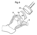
骨盤9を切開した後に、図6に示すように、穴18は、骨9においてつくられる。穴18は、寛骨臼8からの反対側から、そして、股関節19に骨盤を通過する。健康診断は、本願明細書において実施例がそうでありえたいかなるある者にも従って、骨盤9の穴18によって挿入されるために適応させた。この目的のために、医療装置は、穴9によって導入されるために適応する第1および第2の部分から成られることができて、その後で、載置されることができて、はめこんだ医療装置を作製するための元の場所の各々に、機械的に固定することができる。このことは、36hおよび36i、図に関して更に説明される。
After incising the
医療装置、または、医療装置の第1および第2の部分は骨盤9の穴18で導入されるために適応することができる。そして、530のm2または380のmm2より小さい断面領域を有する骨盤9の穴18より小さい断面領域がある、または250のmm2より小さい断面領域を有する骨盤9の穴18または180のmm2より小さい断面領域または110のmm2より小さい断面領域を有する骨盤9の穴18を有する骨盤の穴。
より小さい穴は、医療装置が2つ以上の部分から載置されることを必要とすることが更に考えられるより少ない侵襲的技法を作成する。
若干の実施例において、医療装置は、ベース部分に機械的に接続しているために適応するいくつかの部分から山にされる。
The medical device or the first and second parts of the medical device can be adapted to be introduced in the
Smaller holes create fewer invasive techniques where it is further conceivable that the medical device needs to be mounted from more than one part.
In some embodiments, the medical device is piled up from several parts that are adapted to be mechanically connected to the base part.
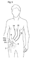
図5はヒト患者の身体の正面の図を示す。そして、寛骨臼8から反対側から股関節を操作する腹腔鏡方法を例示する。股関節は、寛骨臼8と頭大腿骨5とを具備している。
ヒト患者の腹壁の14が患者の身体に腹腔鏡トロカール33a,b,cの挿入に与える小さい切開。
一つ以上のカメラ34、骨盤35の穴をつくるために適応する外科用器具または人工器官または補綴部を導入するか、配置するか、接続するか、取り付けるか、つくるかまたは満たすための器具36が前記腹腔鏡トロカール33a,b,c.による前記本体に嵌入されることができるその後、
FIG. 5 shows a front view of the human patient's body. And the laparoscopic method of operating a hip joint from the opposite side from the
A
One or
図6は、骨を接触させている器官22を用いている寛骨臼の腹部側から、骨盤9の穴18の作成を示す。
FIG. 6 shows the creation of a
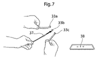
図7は、前記腹腔鏡トロカール33a,b,cによる患者の体に、補綴部38の挿入37のクローズアップを示す。補綴部は、素材が骨盤9においてつくられるホール18を閉めるために用いられるために適応させた人工頭大腿骨45、人工寛骨臼65または補綴部または骨の部でありえた。
FIG. 7 shows a close-up of the
断面に示される股関節については、図8は、ヒト患者の身体の側面図を示す。
股関節に、大腿骨の骨7の最上部である結腸煙突大腿骨6のまさしくその表面に配置される頭大腿骨5が設けられている。頭大腿骨5は、骨盤9のボウル形の部である寛骨臼8と関連してある。腹腔鏡トロカール33a,b,cは、一つ以上のカメラ34を有する股関節39、骨盤9の穴をつくるために適応する外科用器具35または人工器官または補綴部を導入するか、配置するか、接続するか、取り付けるか、つくるかまたは、満たすための器具36に達するために用いられている。
For the hip joint shown in cross section, FIG. 8 shows a side view of the human patient's body.
The hip joint is provided with a
図9は、骨盤9に置かれる人工のボウル形の寛骨臼カップ65を示す。人工のボウル形の寛骨臼カップ65には、第1の状態において、股関節のポジションの結腸煙突大腿骨6に付着するボール形の部分である頭大腿骨5を保持するのに適している部材801を解除することが設けられて、骨盤9に置かれる人工のボウル形の寛骨臼カップ65ように構成されている。
第2の状態において、解除している部材801は頭大腿骨5を解除するために適応する、または、人工代わりは従って、骨盤9に置かれる寛骨臼カップ65を人工のボウルから作り上げた。
予め定められた圧力が解除している部材801に配置されるときに、解除している部材801は第1の状態から第2の状態に変化するために適応する。
好ましくは股関節の異常な動きによって生じている圧力(例えば落下している患者の結果としての)。
図9の図示した実施例によれば、全ての解除している部材801であることを示される実施例で、解除している部材801は、弾性部分から成っている弾性体から成る。
解除している部材は非侵襲的に、第2の状態に対する第1の状態から、そして、第2の状態から第1の状態に変化することが可能であるために適応する。そのとき、予め定められた圧力は解除している部材801に配置される。
FIG. 9 shows an artificial bowl-shaped
In the second state, the releasing
When the predetermined pressure is placed on the releasing
Pressure caused by abnormal movement of the hip joint (eg as a result of a falling patient).
According to the illustrated embodiment of FIG. 9, in the embodiment shown to be all releasing
The releasing member is adapted to be able to change non-invasively from the first state to the second state and from the second state to the first state. At that time, the predetermined pressure is arranged on the
解除している部材801がその第2の状態においてあるときに、図10は断面の股関節を示す。そこにおいて、解除している部材801は頭大腿骨5を解除するために適応する、または、人工代わりは従って、骨盤9に置かれる寛骨臼カップ65を人工のボウルから作り上げた。801が予め定められた圧力のため、第1の状態から第2の状態に変えた解除している部材は、解除している部材801に配置された。
FIG. 10 shows a hip joint in cross section when the releasing
図11は、人工のボウル形の寛骨臼面65が従って、頭大腿骨5または人工代わりに対して摺動するために適応する保持把手802a,bから成っている部材801を解除することから成る実施例に従って、医療装置を示す。
部材がそうである保持は従って、頭大腿骨5または人工代わりを保持に、第1の状態において、適応させた。そして、それは骨盤9に置かれる人工のボウル形の寛骨臼カップ65に股関節のポジションの結腸煙突大腿骨6に付着するボール形の部である。
第2の状態において、解除している部材801は頭大腿骨5を解除するために適応する、または、人工代わりは従って、骨盤9に置かれる寛骨臼カップ65を人工のボウルから作り上げた。
保持把手802a,bは、較正部材(較正ネジ804a,bであること)および保持把手802a,bの間に配置されているバネ803a,bで載せられるばねである。
803a,bが頭大腿骨5を保つために適応する春から保持把手802a,bに動作する力または人工の置換は、従って、通常の、機能的な腰の人工寛骨臼65において運動を接合するが、頭大腿骨5または従って、予め定められた圧力が好ましくは股関節の異常な動きによって生じている解除している部材に配置される人工寛骨臼65から、例えば落下している患者の結果として、人工の置換を解除する。
較正ネジ804a,bは、保持把手802a,bに第1の状態においてあることから第2の状態においてあることに変化させる圧力の予定を可能にする。
FIG. 11 shows that the artificial bowl-shaped
The holding that the member is thus adapted in the first state to hold the
In the second state, the releasing
The holding handles 802a, b are springs mounted by
The force or artificial replacement operating on the holding
図12はそれらの第2の状態の解除している部材を示す。そのとき、予め定められた圧力は上回られた。そして、好ましくは、例えば落下している患者の結果として、股関節の異常な動きによって生じる。
保持把手802a,bは人工の寛骨臼面65のスリーブ806に格納される。それによって、ばね803a,bを圧縮する。
保持把手802a,bの収縮によって従って、頭大腿骨5または人工代わりが生じる。そして、順序を乱されて/人工の寛骨臼面65のそのポジションからluxatedされる。そして、それは大きな圧力が股関節および大腿骨の骨7に配置されるときに、大腿骨の骨7または骨盤9を折っている患者の危険率を低下させる。
保持把手802a,bは非侵襲的に、第2の状態に対する第1の状態から、そして、第2の状態から第1の状態に変化することが可能であるために適応する。そのとき、予め定められた圧力は保持把手802a,bに配置される。
FIG. 12 shows the members released in their second state. At that time, the predetermined pressure was exceeded. And preferably, it is caused by an abnormal movement of the hip joint, for example as a result of a falling patient.
The holding handles 802a and b are stored in the
The contraction of the holding
The holding handles 802a, b are adapted to be able to change non-invasively from the first state to the second state and from the second state to the first state. At that time, a predetermined pressure is placed on the holding handles 802a, b.
図13は保持把手802を有する断面の人工寛骨臼65を示す。そして、従って、頭大腿骨5を保って、人工寛骨臼65または人工代わりの横断面に沿って均一に配布されるスリーブ806に置かれる。そして、人工寛骨臼65において適所にある。
FIG. 13 shows a cross-section
図14は図11−13に示される原理の別の実施例を示す。そこにおいて、保持把手802a,bは従って、頭大腿骨5または人工代わりと接触するボール形の部材805a,bから成る。そして、アリが従って、頭大腿骨5または人工代わりに対して転がるために適応する、頭大腿骨5または従って、従って、頭大腿骨5または人工代わり上の力を振るっている保持把手802a,bによる人工寛骨臼65の場所において、較正ネジ804a,bで支えられるばね803a,bとの接触で人工代わりを保つこと。
FIG. 14 shows another embodiment of the principle shown in FIGS. 11-13. Therein, the holding
図15はそれらの第2の状態の解除している部材を示す。そのとき、予め定められた圧力は上回られた。そして、好ましくは、例えば落下している患者の結果として、股関節の異常な動きによって生じる。保持把手802a,bは、ボール形の部材805a,bから成って、人工の寛骨臼面65のスリーブ806に格納される。それによって、ばね803a,bを圧縮する。保持把手802a,bの収縮によって従って、頭大腿骨5または人工代わりが生じる。そして、順序を乱されて/人工の寛骨臼面65のそのポジションからluxatedされる。そして、それは大きな圧力が股関節および大腿骨の骨7に配置されるときに、大腿骨の骨7または骨盤9を折っている患者の危険率を低下させる。
保持把手802a,bは非侵襲的に、第2の状態に対する第1の状態から、そして、第2の状態から第1の状態に変化することが可能であるために適応する。そのとき、予め定められた圧力は保持把手802a,bに配置される。そして、それは従って、頭大腿骨5または人工の置換を可能にする。そして、外科的手技のない人工寛骨臼65において置き換えられる。
FIG. 15 shows the unlocking members in their second state. At that time, the predetermined pressure was exceeded. And preferably, it is caused by an abnormal movement of the hip joint, for example as a result of a falling patient. The holding handles 802a, b are made of ball-shaped
The holding handles 802a, b are adapted to be able to change non-invasively from the first state to the second state and from the second state to the first state. At that time, a predetermined pressure is placed on the holding handles 802a, b. And it therefore allows for a
図16は、801が適している破裂装置807、808、809から成る解除している部材が予め定められた圧力で故障する実施例の医療装置を示す。この実施例に破裂装置を一致させることは、破裂ピン807、808、809であり、人工寛骨臼65に固定するベース部809a,bと807a,bがそうである破裂部が予め定められた圧力が頭大腿骨5と接触する破裂装置に配置されるベース部809a,bからどの断面を分離したか、弱化セクション808a,bまたはそのための人工代わりによるベース部809a,bに取り付けられる破裂部807a,bとを備えている。
FIG. 16 shows an example medical device in which a releasing member comprising a rupture device 807, 808, 809, for which 801 is suitable, fails at a predetermined pressure. Matching the rupture device to this embodiment is the rupture pins 807, 808, 809, and the
破裂装置が上回られている破裂装置に対する予め定められた負荷のため故障するときに、図17は図16の実施例に従って医療装置を示す。一実施例によれば、破裂部807a,bは、破裂装置の故障の後、さえ、ベース部809a,bに近接してセキュリティ導線を保っている破裂部807a,bによるベース部に固着する(図示されず)。
FIG. 17 illustrates a medical device according to the embodiment of FIG. 16 when the rupture device fails due to a predetermined load on the rupture device being surpassed. According to one embodiment, the
図18aは人工寛骨臼65が円形スリーブ806から成る実施例に従って医療装置を示す。そこにおいて、ゴムまたは破裂バンド810は設けられている。810が部分的に少なくとも適応する伸縮自在のまたは破裂一団は、従って、ボール形の頭大腿骨5または人工代わりを囲む。予め定められた圧力がゴムまたは破裂バンド810に配置されるときに、従って、頭大腿骨5または人工代わりを囲んでいる円形開口部は膨張される、そして、頭大腿骨5または人工代わりは従って、人工寛骨臼65(それが輪ゴム810によって保たれる)から解除される。医療装置が従って、頭大腿骨5または人工代わりを保持している破裂バンド810から成る実施例において、人工寛骨臼65で、バンド810の弱められた部分811は失敗する、そして、このように、従って、頭大腿骨5または人工代わりを囲んでいる円形開口部は膨張される、そして、頭大腿骨5または人工代わりは従って、人工寛骨臼65から解除される。バンド810が輪ゴム810である実施例において、バンド810が弾力的な部または断面から成ることが、または、全てのバンド810が弾性体でできていることが、考えられる。
FIG. 18 a shows a medical device according to an embodiment in which the
ゴムまたは、頭大腿骨5を保って、破裂しているバンド810または人工代わりが従って、人工寛骨臼65の円形スリーブ806に置かれるときに、図18 bは断面の医療装置を示す。開口部または弱められた部分811は、バンド810の円周に対する設けられている垂直である。
FIG. 18 b shows a cross-sectional medical device when the rubber or the
予め定められた汚れがゴムまたは破裂バンド810に配置されたあと、図19aは頭大腿骨5または人工代わりが従って、寛骨臼との関係から解除される第2のステートの医療装置を示す。図19bに示すように、すきままたは弱められた部は膨張された。それによって、従って、頭大腿骨または人工代わりを許容した。そして、開口部を通る流路に対する5がゴムまたは破裂バンド810によって定義された。医療装置は非侵襲的に、第2の状態に対する第1の状態から、そして、第2の状態から第1の状態に変化することが可能であるために適応することができる。そのとき、予め定められた圧力はバンド810に配置される。そして、それは従って、頭大腿骨5または人工の置換を可能にする。そして、外科的手技のない人工寛骨臼65において置き換えられる。
After the predetermined soil has been placed on the rubber or
図20は解除している部材801が人工寛骨臼65の弾力的な翼から成る実施例に従って医療装置を示す。そして、それは従って、頭大腿骨5または従って、頭大腿骨5の位置の向こうに通過している人工寛骨臼65において、人工代わりを囲むことによる医療装置または人工代わりを囲んでいる伸縮自在のまたは破裂バンド810によって援助される。そして、最大の断面距離を有する。ゴムまたは破裂バンド810は、人工寛骨臼65の円周に沿って溝に置かれているバンド810によって、適所に人工寛骨臼65に保持される。しかしながら、前記溝は、援助されることができるかまたは接着剤または機械式固定部材と置き換えられることができる。
FIG. 20 shows a medical device according to an embodiment in which the releasing
人工寛骨臼65から、その第2の状態(解除している部材801が頭大腿骨5を解除する)または人工代わりにおいてとき従って、図21は医療装置を示す。バンド810が輪ゴム810である実施例において、それは膨張される。それによって、頭大腿骨5または人工代わりが従って、通過することができる穴を増大する。バンド810が破裂バンドである実施例において、バンド810は故障した、そして、このことにより、所定の圧力で、頭大腿骨5または人工代わりは従って、頭大腿骨5または従って、人工代わりを解除するために適応する解除している部材801によって単に適切な状態に保たれる。医療装置は非侵襲的に、第2の状態に対する第1の状態から、そして、第2の状態から第1の状態に変化することが可能であるために適応することができる。そのとき、予め定められた圧力はバンド810および/または解除している部材801に配置される。そして、それは従って、頭大腿骨5または人工の置換を可能にする。そして、外科的手技のない人工寛骨臼65において置き換えられる。
Accordingly, FIG. 21 shows the medical device from the
図22は、頭大腿骨5(または人工の置換従って)および結腸煙突大腿骨6が大腿骨の骨7(骨セメントを有するどちらでも)に固定する補綴第818部と置き換えられた実施例に従って、断面の股関節を示す、または、補綴第818部は、破裂バンド813が人工頭大腿骨812の固定部分814に固定した空腔816を有する人工頭大腿骨812を有し、人工寛骨臼65の固定している部分815を備えている。空腔816は、人工頭大腿骨812が人工寛骨臼65内部で通常の機能的な腰運動を実行することを可能にするために適応する。破裂バンド813は、人工頭大腿骨812を第1の状態の人工寛骨臼65に保持して、予め定められた圧力が破裂バンド813に配置される人工寛骨臼から人工頭大腿骨812を解除するために適応する。
FIG. 22 shows that according to an embodiment in which the craniofemoral bone 5 (or artificial replacement) and the
図23は、図22、すぐに破裂バンド813が故障した状態およびこのことにより人工頭大腿骨812による医療装置の実施例が人工寛骨臼65から解除されることを示す。
バンド813がそうでありえた破裂は、人工頭大腿骨812の固定部分814および/または人工寛骨臼65の固定している部分815に用いることを固定させた、最少のある者ネジ、少なくとも一つのピン、形部品、溶接、接着剤、ピン、導線、ボウルに取り付けられるボール、他の部の雌型部に取り付けられるある者部の雄型部分で、キーは、前記部、バンドまたは他の機械式接続部材の部分であることをロックに導入した。例えば落下している患者の結果として、破裂バンド813の欠点は、股関節の異常な動きによって、好ましくは生じる。
FIG. 23 shows that FIG. 22, immediately after the
The rupture that band 813 could have caused at least one minimal screw to be used for
図24は、第1の状態において人工頭大腿骨812および人工寛骨臼65および図9および10の図示した実施例による解除している部材801の固定している部分815の固定部分814に固定する弾力的な屈曲817を用いている人工寛骨臼に保持されると共に、補綴第818部が大腿骨の骨7に固定して、股関節が機能的な股関節運動を実行することを可能にするために適応する空腔816から成っている頭大腿骨812から成る実施例に従って、補綴第818部を示す。解除している部材801の組合せおよび817が適応する輪ゴムは、第1の状態において、人工寛骨臼65に対する、そして、第2の状態の補綴第818部が人工寛骨臼65から補綴第818部を解除すると考える。他の実施例(図示せず)によれば、また、股関節カプセルおよび影響を受けた筋肉の剰余で支えられるコースの中で、補綴部は、単に輪ゴム817を用いているだけの人工寛骨臼65に保持される。
FIG. 24 is secured to the
補綴第818部が人工寛骨臼人工寛骨臼65から解除されるように、817がそうである輪ゴムが伸びた第2の状態で、図25は、図24に従って医療装置の実施例を示す。
817がそうでありえた輪ゴムは、人工頭大腿骨812の固定部分814および/または人工寛骨臼65の固定している部分815に用いることを固定させた、最少のある者ネジ、少なくとも一つのピン、形部品、溶接、接着剤、ピン、導線、ボウルに取り付けられるボール、他の部の雌型部に取り付けられるある者部の雄型部分で、キーは、前記部、バンドまたは他の機械式接続部材の部分であることをロックに導入した。例えば落下している患者の結果として、破裂バンド813の欠点は、股関節の異常な動きによって、好ましくは生じる。好ましくは、輪ゴム817は弾力的な部または断面から成る。そして、それは全ての輪ゴム817(弾性体(例えば弾性ポリマー素材例えば)から作られる)でありえた、共重合体素材(例えばポリスチレン、ポリエステル繊維(エチレン−ブチレン)またはポリスチレン)。素材がエチレンおよび少なくとも一つのビニル単量体(例えばこの種のモノ・カルボン酸酸の酢酸ビニル、不飽和脂肪族モノ・カルボン酸酸およびエステル類)のポリウレタン・エラストマー材、ポリアミド・エラストマー材およびポリエステル・エラストマー材ゴム共重合体であることは、考えられもする。輪ゴム813は障壁被膜から成ることができる。そして、それは体細胞によって突き通られることができない。好ましくは、障壁被膜は、パリレン・コーティングまたは生物学的適合性の金属層(例えば金、銀またはチタン)から成る。他の実施例に輪ゴムを一致させることは、バネ・タイプ部材と、金属およびプラスチック材料の組合せと、金属およびカーボンを主成分とする素材の組合せまたはカーボンの組合せと、プラスチックを主成分とする素材とを備える。
FIG. 25 shows an embodiment of the medical device according to FIG. 24, in a second state in which the
The
図26は、医療装置が大腿骨の骨7に固定するために適応する補綴第819部から成る実施例の断面の股関節を示す。補綴部には、固定する人工寛骨臼65の中に人工頭大腿骨を保持している解除している部材として作用する弾性元素820から成るために適応する人工頭大腿骨が設けられて、骨盤ように構成されている。人工頭大腿骨の中で弾力的な要素820、弾性体(例えばエラストメリック・ポリマー素材または弾性金属素材でありえた)でできていて好ましくはある。弾性体が人工の寛骨臼面との接触から磨耗に抵抗するために適応する人工寛骨臼65と関連して外部層から成ることは、考えられる。予め定められた圧力が股関節上に、そして、このことにより弾性元素820上に配置されるときに、弾性元素は圧縮するために適応する。弾性元素820が圧縮されるときに、人工頭大腿骨は人工寛骨臼65から解除される。
FIG. 26 shows a cross-section hip joint of an embodiment consisting of a
第2の状態において、図27は図26の図示した実施例に従って医療装置を示す。そこにおいて、弾性元素820は圧縮された。そして、医療装置に配置されている予め定められた圧力に続く。医療装置はこのことにより第2の状態に置かれる。そこにおいて、人工頭大腿骨は人工寛骨臼65から解除される。そこにおいて、それは保たれた。
In the second state, FIG. 27 shows the medical device according to the illustrated embodiment of FIG. There, the
図28は弾性元素820が二つゴム要素820と関連してばね821によって更に援助される医療装置の実施例を示す、ばね821は弾性部材820と一緒に圧縮される。そのとき、予め定められた圧力は人工頭大腿骨から成っている補綴第819部に配置される。
FIG. 28 shows an embodiment of a medical device in which the
図29aは、断面の股関節に人工寛骨臼65に、そして、1秒において頭大腿骨5(または人工代わり従って)を保つための医療装置が、第1の状態において、頭大腿骨5または従って、人工寛骨臼65から人工代わりを解除することを述べる時を示す。医療装置は骨盤9および大腿骨の骨7との関係によって医療装置に影響を及ぼしている予め定められた圧力で第2の状態においてあることに第1の状態においてあることから変化に適応する。そして、それは大腿骨の骨7および/または骨盤9を折っている患者の危険率を低下させた。医療装置は、磁石823または人工寛骨臼65に置かれる磁気材料823を有し、磁石822または従って、頭大腿骨5または人工代わりに置かれる磁気材料822を備えている。一実施例によれば、磁石823は従って、頭大腿骨5または人工代わりの方へ向けるその南地磁極を有する人工寛骨臼に置かれる、そして、磁石822が従って、頭大腿骨5または人工代わりに置かれる。そして、人工寛骨臼65の方へ向けるその北のポールを有する。しかしながら、向こう側が単に磁気材料から成ることを必要とするだけであるのに対して、側のある者だけが磁気ことを必要とすることは、技術に熟練しているものによって容易によく理解されている。南北末端および磁石/磁気材料のいかなる組合せも、それ故、考えられる。記載されている磁力は頭大腿骨5(または人工の置換従って)を保つために適応する標準の寛骨臼の、股関節が機能的な股関節運動を実行することを可能にして、用いる、そして、予め定められた圧力が上回られる人工寛骨臼65から、頭大腿骨5または従って、人工の置換を解除する。
FIG. 29a shows that the medical device for keeping the
図29bは第2の状態の図29aの実施例に従って医療装置を示す。そこにおいて、頭大腿骨5または人工代わりは従って、上回られている圧力の所定レベルの結果として、人工寛骨臼65から解除される。
FIG. 29b shows the medical device according to the embodiment of FIG. 29a in the second state. There, the
第1の状態において、図30aは他の実施例に従って医療装置を示す。そこにおいて、医療装置は大腿骨の骨7において固定する補綴第818部から成る。補綴第818部は、結腸煙突大腿骨では配置されている分離線860に沿って分離可能である。骨盤9に対する補綴第818部の安定な固定が可能にされるように、補綴部の近位部分は人工寛骨臼65に置かれて、その中で握られる。分離可能な補綴部によって、補綴部は二つ部861および862から成る。そこにおいて、第1の第861部は人工寛骨臼65に置かれるために適応する、そして、第二部品862は骨盤9に固定するために適応する。最初の861および第2の862の部は、補綴第818部の穴に置かれる破壊ピン863によって、各々に接続している。破壊ピン863はここにある。そして、前記第1の部分861が前記第二ピース862に取り付けた第1のステート保持において、そして、第2の状態において、解除している部材は前記第二ピース862から前記第1の部分861を解除するために破壊に適応させた。破壊ピン863は壊れるために適応して、このことにより第1の状態から第2の状態に変化している。そのとき、予め定められた圧力は解除している部材に配置される。
In the first state, FIG. 30a shows a medical device according to another embodiment. There, the medical device consists of a prosthetic 818 part which is fixed in the
図30bは、破壊ピン863が故障した図30aの実施例に一致していて、このことにより、第1の状態から第二ピース862から第1の部分861を解除している第2の状態に変化している医療装置を示す。
FIG. 30b is consistent with the embodiment of FIG. 30a in which the
図30cおよび30dは、欠陥のある破壊ピン863(図30cに示される)の部分の除去による欠陥のある破壊ピン863の置換および置き換える新規な破壊ピン863(30d、図に示される)を有するそれを示す。結腸煙突大腿骨における、そして、大腿骨の骨5に対する固着のどちらでないも分離線860または骨盤9があることは、それを作る大腿骨の骨5およびまだ、予め定められた値を上回っている力が上回られる第二部品862から初めての第861部を解除している骨盤9その間中のその固着のままの補綴第818部のために人工股関節が固着を傷つけずに順序を乱すことができるように、可能な。
FIGS. 30c and 30d have a new break pin 863 (30d, shown in the figure) that replaces and replaces the
図31は、図式的に、人工寛骨臼がどのように従って、頭大腿骨5か人工代わりの最大直径を越えて進行するかについて示す。すなわち、最大の開口部52の断面距離は、従って、頭大腿骨5または人工代わりで最もかなりの断面距離より小さい
FIG. 31 schematically shows how the artificial acetabulum proceeds over the
図32は、第二ピースがいずれから成るかという実施例に従って、医療装置を示す:
内面906および外面907。内面906は、成る:
第1の位置908a、第2の位置909a、第3の位置908b、第4の位置909b、第5の位置908cおよび6分の1は909cを示す。そして、全ての位置が内面の長さ軸に沿った異なる場所にある。
第1のまっすぐな第910a行は第1の位置908aから第2の909aまで手を伸ばして、第4に対する908bが909bを示す3ポイントめから手を伸ばしている第2のまっすぐな910b線と平行である。そして、それは次々に3本目のまっすぐな910c線と平行である。そして、第6に対する908cが909cを示す5ポイントめから手を伸ばす。
最初の910aおよび3本目の910c直線は第2の直線より短い、そして、第2の直線は第1で3本目の直線の間に位置する。
FIG. 32 shows a medical device according to an example of which the second piece consists of:
The
The first
The first 910a and third 910c straight lines are shorter than the second straight line, and the second straight line is located between the first and third straight lines.
図32cは解除している部材801が従って、医療装置(頭大腿骨5を囲むことによって医療装置を囲んでいる伸縮自在のまたは破裂バンド810によって援助される)または従って、頭大腿骨5の位置の向こうに通過している医療装置において、補綴代わりの弾力的な翼または人工代わりから成る実施例に従って医療装置を示す。そして、最大の断面距離を有する。ゴムまたは破裂バンド810は、医療装置の円周に沿って溝に置かれているバンド810によって、適所に医療装置に保持される。しかしながら、前記溝は、援助されることができるかまたは接着剤または機械式固定部材と置き換えられることができる。
FIG. 32c shows that the unlocking
その第2の状態においてとき、図32dは医療装置を示す。そこにおいて、医療装置から、解除している部材801は従って、頭大腿骨5または人工代わりを解除する。バンド810が輪ゴム810である実施例において、それは膨張されることができる。それによって、頭大腿骨5または補綴置換が従って、通過することができる穴を増大する。バンド810が破裂バンドである実施例において、バンド810は故障する、そして、このことにより、所定の圧力で、頭大腿骨5または補綴置換は従って、頭大腿骨5または従って、補綴置換を解除するために適応する伸びている部分の部である解除している部材801によって単に適切な状態に保たれる。医療装置は非侵襲的に、第2の状態に対する第1の状態から、そして、第2の状態から第1の状態に変化することが可能であるために適応することができる。そのとき、予め定められた圧力はバンド810および/または解除している部材801に配置される。そして、それは従って、頭大腿骨5または補綴置換を可能にする。そして、外科的手技のない医療装置に戻される。
When in its second state, FIG. 32d shows the medical device. There, the releasing
逆の実施例 Reverse example
逆の実施例の一般のバージョンは現在記載されている、逆の実施例の範囲はこの特定のバージョンに決して限られていない、これに反して、上記した実施例の全ては逆の実施例において用いられることができる。 The general version of the reverse embodiment is currently described, the scope of the reverse embodiment is in no way limited to this particular version, whereas all of the above embodiments are in the reverse embodiment. Can be used.
人工の頭大腿骨面112が外科的に修正された頭大腿骨に置かれる凹人工の寛骨臼面110から成っている外科的に修正された頭大腿骨に固定するときに、図33は断面の股関節を示す。図33の図示した実施例によれば、長形部材206は、人工の寛骨臼面を導いて、中央に置いて、案内ロッドおよび股関節の人工の頭大腿骨面として用いられる。表層112が適応する解除している部材801によって確保される凸面股関節は、第1の状態において、人工頭大腿骨を保つ、そして、第2の状態で、人工頭大腿骨を解除する、そして、予め定められた圧力が上回られるときに、第一から第2の状態に変化する。解除している部材は、ネジ121を用いている外科的に修正された頭大腿骨に固定する。係止要素117および凹股関節面117の表層は、凸面股関節面と関連して配置されて、摩擦減衰材料(例えばPTFEまたは自己に油をさしている粉素材)でできていることがありえた。しかしながら、前記医療装置がヒト患者(上記した実施例の全てにおいて考えられる溶液)に植設されたあと、接続表層が医療装置に油をさすために適応する植込み型潤滑装置を用いて油をさされることは、考えられもする。長形部材206が大腿骨の骨によって嵌入されることを明らかにされる実施例によれば、しかしながら図示しない他の実施例によれば、長形部材は、寛骨臼側から股関節の中に配置される。
When the
図34は、骨盤9においてつくられる穴18を占めるために適応する補綴第118部を配置することを示す。補綴第118部は、骨盤9と接触しているのに適しているサポートメンバ119とヒト患者の重量から医療装置に配置される負荷を担持する際の援助とを具備している。さらに、図34は取付けロッド113にナット120の固定を示す。そして、それは案内ロッドとして作用する長形部材206によって次々に導かれる。
FIG. 34 shows the placement of a
装置がそうであった健康診断の全ての要素が股関節またはその環境では固定するときに、図35は断面の股関節を示す。補綴第113部が9がネジ121で固定してここである骨盤の穴18を占めるために適応して、しかしながら、これらのネジ121は、援助されることができるかまたは補綴部および骨盤9の間で表層Sに適用されることがありえた接着剤と交換されることができる。案内ロッドとして作用する長形部材206は、大腿の切開によって格納された。
FIG. 35 shows a cross-section hip joint when all elements of the health check that the device has been secured in the hip joint or its environment. The
本願明細書において実施例のいずれかの弾力的であるか柔軟な部、部分または部分は、例えば弾性ポリマー素材から成ることができる:
共重合体素材(例えばポリスチレン、ポリエステル繊維(エチレン−ブチレン)またはポリスチレン)。
素材がエチレンおよび少なくとも一つのビニル単量体(例えばこの種のモノ・カルボン酸酸の酢酸ビニル、不飽和脂肪族モノ・カルボン酸酸およびエステル類)のポリウレタン・エラストマー材、ポリアミド・エラストマー材およびポリエステル・エラストマー材ゴム共重合体であることは、考えられもする。
輪ゴム813は障壁被膜から成ることができる。そして、それは体細胞によって突き通られることができない。
好ましくは、障壁被膜は、パリレン・コーティングまたは生物学的適合性の金属層(例えば金、銀またはチタン)から成る。
他の実施例に輪ゴムを一致させることは、バネ・タイプ部材と、金属およびプラスチック材料の組合せと、金属およびカーボンを主成分とする素材の組合せまたはカーボンの組合せと、プラスチックを主成分とする素材とを備える。
The elastic or flexible part, part or part of any of the examples herein can consist of, for example, an elastic polymer material:
Copolymer material (for example, polystyrene, polyester fiber (ethylene-butylene) or polystyrene).
Polyurethane elastomer materials, polyamide elastomer materials and polyesters of ethylene and at least one vinyl monomer (eg vinyl acetate of such mono-carboxylic acids, unsaturated aliphatic mono-carboxylic acids and esters) -It may be considered that it is an elastomer rubber copolymer.
The
Preferably, the barrier coating consists of a parylene coating or a biocompatible metal layer (eg gold, silver or titanium).
Matching the rubber bands to other embodiments includes a spring-type member, a combination of metal and plastic material, a combination of materials based on metal and carbon or a combination of carbon, and a material based on plastic With.
人工寛骨臼は、実施例のいずれかに従って、少なくとも一つのネジ、少なくとも一つのピン、他の部に導入されるために適応する部の少なくとも1つの少なくとも一つの部分を用いている骨盤に固定することができる一つ以上の部から成ることができる。そして、部が他の部に摺動しているために適応する、形部品、溶接、接着剤、ピン、導線、ボールは、ボウルに前記部(他の部の雌型部に取り付けられるある者部の雄型部分)の部分であることを取り付けたキーが、前記部の部分、バンドまたは他の機械式接続部材であることをロックに導入した。 An artificial acetabulum is secured to the pelvis using at least one screw, at least one pin, at least one part of the part adapted to be introduced into another part, according to any of the embodiments It can consist of one or more parts that can be. And adaptable because the part slides on the other part, shaped parts, welds, adhesives, pins, conductors, balls are attached to the above part (other part female mold part) to the bowl It was introduced to the lock that the key attached to that part was the part, band or other mechanical connection member.
図36aは116がそうであるロック部材が人工の寛骨臼面(1340in図36b)に人工頭大腿骨112をロックに、第1の状態において、適応させたことを係止/解除している部材116(係止/解除している部材116が股関節面に対して人工の凸面股関節面(図36bの112)(第1の部分であること)およびスライドと接触してあるために適応する表層1353から成る)の実施例に明らかにする、そして、中で、1秒は述べる、前記人工寛骨臼1340から前記人工頭大腿骨112を解除する。圧力の予め定められた量が係止/解除している部材116に配置されるときに、係止/解除している部材116は第一から第2の状態に変化するために適応する。図28bの図示した実施例による係止/解除している部材116は4つの保持把手から成る、ここでは、弾力的な部分1351および係止/解除している部材116であること第一から弾力的な部分1351の弾力を用いている第2の状態まで変化に適応する。ロック部材116は、したがって適応する穴1352に置かれるために適応するネジを用いている大腿骨の骨7に固定するために適応する。他の実施例(図示せず)に保持把手1351を一致させることに、部材を第1の部分に対して転がるのに適していて、人工の凸面股関節面112である状態に少なくとも一つに保つことが設けられている。
FIG. 36a locks / releases the locking
部材116を係止していて/解除している二つ状態が人工頭大腿骨112を人工寛骨臼1340に固定するときに、図36bは断面の股関節を示す。部材116を係止していて/解除している二つ状態は、ネジ121を用いている大腿骨の骨7に固定して、係止/解除している部材116が人工寛骨臼1340に人工頭大腿骨112を係止するその第1の状態に示されて、ここにある。
FIG. 36b shows a cross-section hip joint when the two states locking / unlocking
図36cは図36bの実施例に従う断面の股関節、しかし、二つが部材116を係止して/解除することがその第2の状態においてあると述べる時を示す。そこにおいて、係止/解除している部材116は人工の寛骨臼面1340から人工頭大腿骨112を解除する。係止/解除している部材116を有する構造は、固定位置(すなわち骨との接触)を傷つけている人工関節に配置される圧力の危険率を低下させる。それは、更に人工関節が脱臼の場合には非侵襲的に再配置されることを可能にする。
FIG. 36c shows a hip joint in cross section according to the embodiment of FIG. 36b, but when two state that locking / releasing
図36dは部材116を係止していて/解除している二つ−状態の別の実施例を示す。そこにおいて、植設されるときに、部材116を係止していて/解除している二つ−状態は人工頭大腿骨112を囲むために適応する輪ゴム1361から更に成る。輪ゴム1361は、弾力的なポリマー・バンド(例えばポリウレタンまたはシリコーン・バンド)でありえた。
FIG. 36d shows another example of a two-state locking / releasing
部材116を係止していて/解除している二つ−状態が植設されて、その第1のステートにあるときに、図36eは断面の股関節を示す。部材116を係止していて/解除している二つ−状態は、ネジ121を用いている大腿骨の骨7に固定する。
When the two-state locking / unlocking
その第2の状態においてとき、図36fは部材116を係止していて/解除している二つ−状態から成っている移植可能デバイスに明らかにする、すなわち、人工頭大腿骨112が人工寛骨臼1340から出ることができるように、係止/解除している部材116が適応する状態で、112がそうである人工頭大腿骨を囲んでいる輪ゴム1361による人工頭大腿骨112を解除することは伸びた。係止/解除している部材116を有する構造は、固定位置(すなわち骨との接触)を傷つけている人工関節に配置される圧力の危険率を低下させる。それは、更に人工関節が脱臼の場合には非侵襲的に再配置されることを可能にする。
When in its second state, FIG. 36f reveals a two-state implantable device locking / releasing
係止/解除している部材116は36a、図に関して記載した−36fは、しかしながら、補綴第118部によって占められる骨盤9の大きな穴を有する実施例において表される、二つが部材116を係止して/解除することが骨盤9の小開口を有する実施例において用いられると述べることは等しく考えられる。そして、より少ない侵襲的技法間である、医療装置の中で開示される実施例の全部が従来の開いた股関節外科的手技の間、取り付けられることができることはさらに、考えられる。そして、股関節カプセルを突き通った。この場合、部材116を係止していて/解除している二つ状態は、完全な人工器官(例えば図22 ― 28 ― に関して開示される人工器官)の部でありえた。
Locking / unlocking
図36gは係止/解除している部材116の実施例を示す。そこにおいて、係止/解除している部材116は第1の状態から人工寛骨臼1340から人工頭大腿骨112を解除するための第2の状態に変化するために必要な弾力をつくっているばね1371から成る。圧力の予め定められた量が係止/解除している部材116に配置されるときに、係止/解除している部材116は第一から第2の状態に変化するために適応する。図の図示した実施例に36gにより深い医療装置を与えることは、第一から第2の状態までの弾力を調整するためのばね1371と関連して配置される較正ネジ1372およびこのことにより係止/解除している部材が変化することを必要とする圧力の量を備えている。
FIG. 36g shows an embodiment of the
係止/解除している116の部材が第一から第2の状態に変化することができるために、図36hは、係止/解除している部材が予め定められた圧力で失敗するために適応する4本の破裂ピン1373から成る係止/解除している部材の実施例を示す。ピンは、この実施例に従って、特定の患者のために適応することができるもろい素材から作られる。他の実施例(図示せず)において、破裂pins1373は破裂バンドと交換されることができる。そして、輪ゴムと同様であるが、予め定められた圧力で失敗するために適応する、または、破裂バンドが中央に配置されて、図23に関して例えば開示される。
FIG. 36h shows that the locking / unlocking member fails at a predetermined pressure because the 116 locking / unlocking members can change from the first to the second state. An embodiment of a locking / unlocking member consisting of four adapted bursting
二つ部1375aおよび1375bから成っている人工頭大腿骨1375a,bが相互に連結した人工頭大腿骨を形成するために相互接続するために適応するときに、図36iは断面の股関節を示す。各々の二つ人工の部1375a(1375b)はさらに、固定している部分1374aから成る。そして、1374bが寛骨臼8の内部に固定するために適応する。逆の実施例の機能的な股関節をつくるために、人工頭大腿骨は、相互接続の後、大腿骨の骨7の近位部分に置かれる人工凹寛骨臼1340に置かれるために適応する。
Figure 36i shows a cross-section hip joint when the
相互に連結した人工頭大腿骨1375が寛骨臼8に置かれて、固定している部分1374を用いて固定するときに、図36jは断面の股関節を示す。係止/解除している部材116は、人工頭大腿骨1375が配置されることを可能にすることを必要とする弾力をつくっているばね1371を用いている人工頭大腿骨1375上に配置された係止/解除している部材締金人工的な頭大腿骨1375。
FIG. 36 j shows a cross-section hip joint when the interconnected
部材116を係止していて/解除している二つ状態が相互に連結した人工頭大腿骨1375を人工寛骨臼1340に固定するときに、図36kは断面の股関節を示す。部材116を係止していて/解除している二つ状態は、ネジ121を用いている大腿骨の骨7に固定して、係止/解除している部材116が人工寛骨臼1340に人工頭大腿骨112を係止するその第1の状態に示されて、ここにある。
FIG. 36k shows a cross-sectional hip joint when the
図36mは36k、図の実施例に従って断面の股関節を示す、しかし、2つが部材を係止して/解除することを述べるときに、116はその第2の状態においてある。そこにおいて、必要な弾力をつくっているばね1371によって、係止/解除している部材116は人工の寛骨臼面1340から人工頭大腿骨112を解除する。係止/解除している部材116を有する構造は、固定位置(すなわち骨との接触)を傷つけている人工関節に配置される圧力の危険率を低下させる。それは、更に人工関節が脱臼の場合には非侵襲的に再配置されることを可能にする。
FIG. 36m shows a hip joint in cross section according to the illustrated embodiment, 36k, but 116 is in its second state when two states locking / releasing the member. There, the locking / unlocking
実施例のいかなる実施例もまたは部がいかなる形であれいかなる方法または方法の部と同様に結合されることができる点に注意します。本願明細書において全ての実施例は、一般にいかなる形であれ組み合わさる一般的説明、したがって候補者の一部として見られなければならない。 Note that any embodiment or part of the embodiment can be combined in any way as well as any method or part of the method. All examples herein should generally be viewed as part of the general description, thus combining in any form.
Claims (48)
i. 前記第1の部分は、骨盤に固定するために適応し、
ii.凹接触表面に部分的に置かれるのに適している凸面接触表面が設けられており、
b.第2の部分は、、
i.大腿骨の骨に固定するために適応し、
ii.植設されるときに、前記第の部分は部分的に前記第1の部分の前記凸面接触表面を囲むために適応する凹接触表面から成り、
c.前記第1の部分が前記第2の部分に取り付けた第1のステート保持に、適応することの解除している部材およびすぐに状態は前記第2の部分から前記第1の部分を解除する、そして、予め定められた圧力が前記解除している部材に配置されるときに、前記解除している部材は前記第1の状態から前記第2の状態に変化するために適応する患者の股関節の移植のための医療装置。 a. The first part is
i. The first portion is adapted for fixation to the pelvis;
ii. A convex contact surface is provided that is suitable for being partially placed on the concave contact surface;
b. The second part is
i. Adapted to fix to the femur bone,
ii. When implanted, the first portion comprises a concave contact surface adapted to partially surround the convex contact surface of the first portion;
c. The first portion attached to the second portion is adapted to hold the first state holding member and immediately the state releases the first portion from the second portion; And when a predetermined pressure is arranged on the releasing member, the releasing member is adapted to change from the first state to the second state of the patient's hip joint. Medical device for transplantation.
b.骨盤に前記医療装置の前記第1の部分を固定させるステップと、
c.大腿骨の骨に前記医療装置の前記第2の部分を固定させるステップと、
d.前記第2の部分と関連して前記第1の部分を配置するステップと、
e.前記解除している部材を用いている前記第2の部分に対する前記第1の部分を保つステップと、から成る、
請求項1−42いずれかに記載のヒト患者の股関節に医療装置を取り付ける方法。 a. Exposing the hip joint by a surgical or arthroscopic procedure;
b. Securing the first portion of the medical device to the pelvis;
c. Securing the second portion of the medical device to a femoral bone;
d. Positioning the first portion relative to the second portion;
e. Holding the first part relative to the second part using the releasing member;
43. A method of attaching a medical device to a hip joint of a human patient according to any one of claims 1-42.
Applications Claiming Priority (70)
| Application Number | Priority Date | Filing Date | Title |
|---|---|---|---|
| SE0900968-9 | 2009-07-10 | ||
| SE0900973-9 | 2009-07-10 | ||
| SE0900969-7 | 2009-07-10 | ||
| SE0900978-8 | 2009-07-10 | ||
| SE0900965-5 | 2009-07-10 | ||
| SE0900970-5 | 2009-07-10 | ||
| SE0900968 | 2009-07-10 | ||
| SE0900970 | 2009-07-10 | ||
| SE0900981-2 | 2009-07-10 | ||
| SE0900957 | 2009-07-10 | ||
| SE0900962 | 2009-07-10 | ||
| SE0900959-8 | 2009-07-10 | ||
| SE0900972-1 | 2009-07-10 | ||
| SE0900957-2 | 2009-07-10 | ||
| SE0900974-7 | 2009-07-10 | ||
| SE0900972 | 2009-07-10 | ||
| SE0900958 | 2009-07-10 | ||
| SE0900962-2 | 2009-07-10 | ||
| SE0900960-6 | 2009-07-10 | ||
| SE0900976 | 2009-07-10 | ||
| SE0900966-3 | 2009-07-10 | ||
| SE0900966 | 2009-07-10 | ||
| SE0900963 | 2009-07-10 | ||
| SE0900960 | 2009-07-10 | ||
| SE0900974 | 2009-07-10 | ||
| SE0900965 | 2009-07-10 | ||
| SE0900958-0 | 2009-07-10 | ||
| SE0900973 | 2009-07-10 | ||
| SE0900978 | 2009-07-10 | ||
| SE0900981 | 2009-07-10 | ||
| SE0900963-0 | 2009-07-10 | ||
| SE0900969 | 2009-07-10 | ||
| SE0900976-2 | 2009-07-10 | ||
| SE0900959 | 2009-07-10 | ||
| US22976709P | 2009-07-30 | 2009-07-30 | |
| US22973909P | 2009-07-30 | 2009-07-30 | |
| US22975109P | 2009-07-30 | 2009-07-30 | |
| US22973509P | 2009-07-30 | 2009-07-30 | |
| US22973809P | 2009-07-30 | 2009-07-30 | |
| US22974309P | 2009-07-30 | 2009-07-30 | |
| US22978909P | 2009-07-30 | 2009-07-30 | |
| US22977809P | 2009-07-30 | 2009-07-30 | |
| US22974809P | 2009-07-30 | 2009-07-30 | |
| US22978609P | 2009-07-30 | 2009-07-30 | |
| US22975209P | 2009-07-30 | 2009-07-30 | |
| US22976109P | 2009-07-30 | 2009-07-30 | |
| US22974609P | 2009-07-30 | 2009-07-30 | |
| US22975509P | 2009-07-30 | 2009-07-30 | |
| US22974509P | 2009-07-30 | 2009-07-30 | |
| US22974709P | 2009-07-30 | 2009-07-30 | |
| US22979609P | 2009-07-30 | 2009-07-30 | |
| US61/229,735 | 2009-07-30 | ||
| US61/229,778 | 2009-07-30 | ||
| US61/229,748 | 2009-07-30 | ||
| US61/229,796 | 2009-07-30 | ||
| US61/229,746 | 2009-07-30 | ||
| US61/229,767 | 2009-07-30 | ||
| US61/229,761 | 2009-07-30 | ||
| US61/229,747 | 2009-07-30 | ||
| US61/229,789 | 2009-07-30 | ||
| US61/229,751 | 2009-07-30 | ||
| US61/229,786 | 2009-07-30 | ||
| US61/229,745 | 2009-07-30 | ||
| US61/229,752 | 2009-07-30 | ||
| US61/229,743 | 2009-07-30 | ||
| US61/229,738 | 2009-07-30 | ||
| US61/229,739 | 2009-07-30 | ||
| US61/229,755 | 2009-07-30 | ||
| PCT/SE2010/050821 WO2011005202A1 (en) | 2009-07-10 | 2010-07-12 | Hip joint device and method |
| PCT/SE2010/050806 WO2011005190A1 (en) | 2009-07-10 | 2010-07-12 | Hip joint device and method |
Related Child Applications (1)
| Application Number | Title | Priority Date | Filing Date |
|---|---|---|---|
| JP2015062524A Division JP5977391B2 (en) | 2009-07-10 | 2015-03-25 | Medical device implanted in the patient's hip joint |
Publications (2)
| Publication Number | Publication Date |
|---|---|
| JP2012532662A true JP2012532662A (en) | 2012-12-20 |
| JP2012532662A5 JP2012532662A5 (en) | 2013-08-29 |
Family
ID=48446000
Family Applications (1)
| Application Number | Title | Priority Date | Filing Date |
|---|---|---|---|
| JP2012519512A Pending JP2012532662A (en) | 2009-07-10 | 2010-07-12 | Hip apparatus and method |
Country Status (7)
| Country | Link |
|---|---|
| US (2) | US9271838B2 (en) |
| EP (2) | EP2451397B1 (en) |
| JP (1) | JP2012532662A (en) |
| AU (5) | AU2010269155B2 (en) |
| CA (1) | CA2805011C (en) |
| MX (1) | MX2012000518A (en) |
| WO (2) | WO2011005190A1 (en) |
Families Citing this family (11)
| Publication number | Priority date | Publication date | Assignee | Title |
|---|---|---|---|---|
| US20110166671A1 (en) | 2006-11-07 | 2011-07-07 | Kellar Franz W | Prosthetic joint |
| US9005307B2 (en) * | 2006-11-07 | 2015-04-14 | Biomedflex, Llc | Prosthetic ball-and-socket joint |
| US8308812B2 (en) | 2006-11-07 | 2012-11-13 | Biomedflex, Llc | Prosthetic joint assembly and joint member therefor |
| US11039929B2 (en) * | 2009-07-10 | 2021-06-22 | Peter Mats Forsell | Hip joint device and method |
| ES2553392T3 (en) * | 2009-07-10 | 2015-12-09 | Kirk Promotion Ltd. | Hip joint device |
| US8313531B2 (en) | 2010-03-08 | 2012-11-20 | Hip Innovation Technology Llc | Interlocking reverse hip prosthesis and method |
| CA2838556C (en) * | 2011-08-08 | 2016-06-07 | Hip Innovation Technology Llc | Orthopedic instrument, system and method for implanting an acetabular cup |
| US9492184B2 (en) * | 2013-08-05 | 2016-11-15 | William B. Kurtz | Hip replacement systems and methods |
| EP3053547B1 (en) * | 2015-02-04 | 2017-07-19 | Alessandro Melozzi | Improved hip prosthesis |
| US11090163B1 (en) * | 2021-01-09 | 2021-08-17 | Zafer Termanini | Interlocking reverse hip prosthesis with removable tapered central post |
| PL245014B1 (en) * | 2023-03-01 | 2024-04-15 | Radon Stanislaw | Hip endoprosthesis |
Citations (2)
| Publication number | Priority date | Publication date | Assignee | Title |
|---|---|---|---|---|
| US4044403A (en) * | 1976-11-01 | 1977-08-30 | Howmedica, Inc. | Implantable joint prosthesis |
| EP1421919A1 (en) * | 2002-11-05 | 2004-05-26 | ESKA Implants GmbH & Co. | Set for constructing an artificial hip joint |
Family Cites Families (79)
| Publication number | Priority date | Publication date | Assignee | Title |
|---|---|---|---|---|
| FR1047640A (en) * | 1952-01-10 | 1953-12-15 | New joint prosthesis for surgical use | |
| CH514331A (en) * | 1969-05-23 | 1971-10-31 | Osteo Ag | Hip joint prosthesis |
| US3683421A (en) * | 1970-07-13 | 1972-08-15 | Skf Ind Inc | Prosthetic joint assembly |
| US3744061A (en) * | 1971-09-13 | 1973-07-10 | H Frost | Artificial hip joint and method of implanting in a patient |
| US3818512A (en) * | 1973-05-08 | 1974-06-25 | Y Shersher | Artificial hip-joint with detachable insert |
| US3864758A (en) * | 1973-08-31 | 1975-02-11 | Sam Savo Yakich | Hip joint bearing prosthesis |
| US4024588A (en) * | 1974-10-04 | 1977-05-24 | Allo Pro A.G. | Artificial joints with magnetic attraction or repulsion |
| US3916451A (en) * | 1974-10-25 | 1975-11-04 | Frederick F Buechel | Floating center prosthetic joint |
| US4135517A (en) * | 1977-07-21 | 1979-01-23 | Minnesota Mining And Manufacturing Company | Femoral prosthesis trial fitting device |
| US4159544A (en) * | 1977-11-28 | 1979-07-03 | Zafmedico Corporation | Hip joint prosthesis |
| US4206517A (en) | 1977-12-01 | 1980-06-10 | Biomedical Engineering Corp. | Floating center prosthetic joint |
| DE2829676A1 (en) | 1978-07-06 | 1980-01-24 | Gmt Medizinische Technik Gmbh | ENDOPROTHESIS |
| US4241463A (en) * | 1978-10-16 | 1980-12-30 | Precision Cast Specialties, Inc. | Prosthetic implant device |
| EP0051686B1 (en) * | 1980-11-06 | 1986-07-30 | Waldemar Link (GmbH & Co.) | Joint endoprosthesis |
| US4624674A (en) * | 1982-02-24 | 1986-11-25 | Pappas Michael J | Spherical kinematic joint |
| US4678472A (en) * | 1983-03-08 | 1987-07-07 | Joint Medical Products Corporation | Ball and socket bearing for artificial joint |
| US4950299A (en) | 1983-03-08 | 1990-08-21 | Joint Medical Products Corporation | Ball and socket bearing for artificial joint |
| US4770659A (en) * | 1984-03-07 | 1988-09-13 | Kendall Richard L | Femoral prosthesis with forced motion sharing |
| FR2582934B1 (en) | 1985-06-10 | 1989-07-07 | Moulin Jacques | TOTAL HIP PROSTHESIS WITH LONG-TERM ACTION PROHIBITING ALL LUXATION |
| FR2589059B1 (en) * | 1985-10-25 | 1988-01-08 | Duthoit Etienne | COTYLOIDAL COMPONENT FOR NON-CEMENTED HIP PROSTHESIS |
| US4784663A (en) * | 1986-02-19 | 1988-11-15 | Pfizer Hospital Products Group, Inc. | Acetabular cup assembly |
| CH669903A5 (en) * | 1986-04-15 | 1989-04-28 | Sulzer Ag | |
| US4731088A (en) * | 1986-06-02 | 1988-03-15 | Boehringer Mannheim Corp | Enclosure member for prosthetic joint |
| US4714477A (en) * | 1986-08-08 | 1987-12-22 | Dow Corning Wright Corporation | Ball-and-socket joint prosthesis with bearing insert |
| US4846840A (en) * | 1986-09-09 | 1989-07-11 | Sylvain Leclercq | Joint prosthesis |
| US4770658A (en) * | 1987-05-01 | 1988-09-13 | Zimmer, Inc. | Joint prosthesis |
| US5092898A (en) * | 1988-05-31 | 1992-03-03 | Ngk Spark Plug Co., Ltd. | Artificial joint |
| US4936855A (en) * | 1989-04-24 | 1990-06-26 | Intermedics, Orthopedics, Inc. | Stepped-lock ring system for implantable joint prostheses |
| US5019105A (en) * | 1989-08-03 | 1991-05-28 | Biomet, Inc. | Acetabular cup prosthesis assembly |
| US5062853A (en) * | 1989-08-08 | 1991-11-05 | Forte Mark R | Bipolar femoral implant |
| ATE124620T1 (en) * | 1991-01-18 | 1995-07-15 | Sulzer Medizinaltechnik Ag | IMPLANT MADE OF TWO SLIDER PARTNERS. |
| DE9212419U1 (en) * | 1992-09-15 | 1994-01-27 | Waldemar Link GmbH & Co, 22339 Hamburg | Joint socket for a hip joint endoprosthesis |
| DE29513694U1 (en) * | 1995-08-25 | 1997-01-02 | Waldemar Link GmbH & Co, 22339 Hamburg | Joint socket for an endoprosthesis |
| US20020143402A1 (en) * | 1995-09-04 | 2002-10-03 | Limber Ltd. | Hip joint prostheses |
| IL115168A0 (en) * | 1995-09-04 | 1995-12-31 | Steinberg Gal | Joints |
| US5755807A (en) * | 1996-06-17 | 1998-05-26 | Folsom Metal Products | Implant module unit and rotating seal for prosthetic joint |
| US5800555A (en) * | 1997-04-24 | 1998-09-01 | Depuy Orthopaedics, Inc. | Acetabular cup bearing liner |
| US5879406A (en) * | 1997-07-15 | 1999-03-09 | Saint-Gobain Industrial Ceramics, Inc. | Artificial joint bioprosthesis for mitigation of wear |
| US6206929B1 (en) * | 1998-03-27 | 2001-03-27 | Depuy Orthopaedics, Inc. | Bipolar hip prosthesis with locking head |
| US6010535A (en) | 1998-04-30 | 2000-01-04 | Shah; Mrugesh K. | Joint replacement system |
| IT245363Y1 (en) * | 1998-05-12 | 2002-03-20 | Tian Enrico | ANTI-LUXURY ANKLE PROSTHESIS |
| US5989294A (en) * | 1998-07-29 | 1999-11-23 | Marlow; Aaron L. | Ball-and-socket joint, particularly a prosthetic hip joint |
| DE19843797A1 (en) | 1998-09-24 | 2000-03-30 | Gmt Medizinische Technik Gmbh | Socket unit for an artificial hip joint comprises a raised section which partially surrounds the spherical joint head accommodated in the socket |
| WO2000057820A1 (en) * | 1999-03-31 | 2000-10-05 | Stocks Gregory W | Joint prosthesis assembly and method for installing same |
| DE19924676A1 (en) * | 1999-05-29 | 2000-11-30 | Dietmar Wolter | Hip prosthesis |
| US20030236572A1 (en) * | 2000-10-18 | 2003-12-25 | Morton Bertram | Total joint replacements using magnetism to control instability |
| DE10103482C2 (en) * | 2001-01-26 | 2002-12-19 | Mathys Medizinaltechnik Ag Bet | expandable socket |
| EP1411868A4 (en) * | 2001-07-31 | 2006-04-12 | Biomet Inc | Method and apparatus for use of a metal-metal constrained liner |
| KR200264044Y1 (en) * | 2001-08-21 | 2002-02-19 | 김성곤 | Artificial Hip Joint Prosthesis |
| ATE457707T1 (en) | 2001-12-04 | 2010-03-15 | Active Implants Corp | CUSHION BEARING IMPLANTS FOR LOAD-BEARING APPLICATIONS |
| US6916342B2 (en) * | 2002-04-01 | 2005-07-12 | Smith & Nephew, Inc. | Liner assembly for prosthetic components |
| US6923833B2 (en) * | 2002-04-09 | 2005-08-02 | Ray C. Wasielewski | Biologically reabsorbable acetabular constraining components and materials for use with a hip replacement prosthesis and bioreabsorbable materials to augment hip replacement stability and function |
| US6761741B2 (en) * | 2002-06-10 | 2004-07-13 | Kazuho Iesaka | Prosthetic joint |
| FR2841768B1 (en) * | 2002-07-05 | 2005-05-06 | Tornier Sa | SHOULDER OR HIP PROSTHESIS FACILITATING ABDUCTION |
| US8062376B2 (en) * | 2002-07-10 | 2011-11-22 | Biomet Manufacturing Corp. | Shoulder implant assembly |
| US7175663B1 (en) * | 2003-10-08 | 2007-02-13 | Biomet Manufacturing Corp. | Shoulder implant assembly |
| US6986792B2 (en) * | 2002-09-13 | 2006-01-17 | Smith & Nephew, Inc. | Prostheses |
| US7115145B2 (en) * | 2003-07-03 | 2006-10-03 | Zimmer, Inc. | Acetabular component |
| DE102005030747B4 (en) * | 2005-06-29 | 2012-12-27 | Zf Friedrichshafen Ag | ball joint |
| US8002842B2 (en) | 2005-11-07 | 2011-08-23 | Biomet Manufacturing Corp. | Method and apparatus for reducing rim loading of an acetabular shell |
| WO2007084939A2 (en) * | 2006-01-20 | 2007-07-26 | Zimmer Technology, Inc. | Shoulder arthroplasty system |
| US8308811B2 (en) * | 2006-04-11 | 2012-11-13 | Zimmer, Inc. | Acetabular cup conversion ring |
| DE102007031667A1 (en) * | 2006-08-04 | 2008-02-14 | Ceramtec Ag Innovative Ceramic Engineering | Insertion of vibration-damping elements in prosthetic systems for manipulation and damping of natural frequencies |
| US7905919B2 (en) * | 2006-11-07 | 2011-03-15 | Biomedflex Llc | Prosthetic joint |
| US7914580B2 (en) * | 2006-11-07 | 2011-03-29 | Biomedflex Llc | Prosthetic ball-and-socket joint |
| WO2008063500A1 (en) * | 2006-11-13 | 2008-05-29 | Lewis Ralph H | Extended range of motion, constrained prosthetic hip-joint |
| AU2007333133B2 (en) * | 2006-12-12 | 2013-07-04 | Exactech, Inc. | Constrained acetabular cup liner locking ring and polyethylene liner congruency feature |
| US8211182B2 (en) * | 2007-09-17 | 2012-07-03 | Linares Medical Devices, Llc | Hip socket with assembleable male ball shape having integrally formed ligament and female receiver and installation kit |
| US8257363B2 (en) * | 2007-10-12 | 2012-09-04 | Howmedica Osteonics Corp. | Expandable reverse shoulder trial |
| DE102007053362B4 (en) * | 2007-11-06 | 2014-06-05 | Universität Rostock | Magnetically stored artificial joint |
| US8454703B2 (en) * | 2008-05-21 | 2013-06-04 | Linares Medical Devices, Llc | Shoulder implant with first and second composite sub-assemblies and improved mounting anchors for establishing a secure joint |
| DE102008058153A1 (en) * | 2008-11-20 | 2010-05-27 | Aesculap Ag | acetabulum |
| GB2467991B (en) * | 2009-02-19 | 2011-01-05 | Implant Prot Ltd | Prosthetic implant device |
| WO2011005184A1 (en) * | 2009-07-10 | 2011-01-13 | Milux Holding S.A. | Hip joint device |
| US8313531B2 (en) * | 2010-03-08 | 2012-11-20 | Hip Innovation Technology Llc | Interlocking reverse hip prosthesis and method |
| US8142511B2 (en) * | 2010-04-19 | 2012-03-27 | Zimmer, Inc. | Bi-material prosthesis component |
| US8465549B2 (en) * | 2011-02-16 | 2013-06-18 | Rodney Ian Walter Richardson | Acetabular cup with rotatable bearing |
| US8747481B2 (en) * | 2011-04-21 | 2014-06-10 | Brian Ted Maurer | Reverse joint replacement device and methods thereof |
| US9060862B2 (en) * | 2011-07-08 | 2015-06-23 | Floyd Franklin Castro | Semi-constrained ball and socket joints |
-
2010
- 2010-07-12 US US13/383,276 patent/US9271838B2/en active Active
- 2010-07-12 US US13/383,024 patent/US8920510B2/en active Active
- 2010-07-12 AU AU2010269155A patent/AU2010269155B2/en active Active
- 2010-07-12 JP JP2012519512A patent/JP2012532662A/en active Pending
- 2010-07-12 EP EP10797409.9A patent/EP2451397B1/en active Active
- 2010-07-12 EP EP10797397.6A patent/EP2451392B1/en active Active
- 2010-07-12 CA CA2805011A patent/CA2805011C/en active Active
- 2010-07-12 MX MX2012000518A patent/MX2012000518A/en active IP Right Grant
- 2010-07-12 WO PCT/SE2010/050806 patent/WO2011005190A1/en active Application Filing
- 2010-07-12 WO PCT/SE2010/050821 patent/WO2011005202A1/en active Application Filing
-
2016
- 2016-01-29 AU AU2016200533A patent/AU2016200533B2/en active Active
-
2018
- 2018-01-02 AU AU2018200035A patent/AU2018200035B2/en active Active
-
2019
- 2019-10-11 AU AU2019246896A patent/AU2019246896B2/en active Active
-
2021
- 2021-04-21 AU AU2021202426A patent/AU2021202426B2/en active Active
Patent Citations (2)
| Publication number | Priority date | Publication date | Assignee | Title |
|---|---|---|---|---|
| US4044403A (en) * | 1976-11-01 | 1977-08-30 | Howmedica, Inc. | Implantable joint prosthesis |
| EP1421919A1 (en) * | 2002-11-05 | 2004-05-26 | ESKA Implants GmbH & Co. | Set for constructing an artificial hip joint |
Also Published As
| Publication number | Publication date |
|---|---|
| EP2451392A4 (en) | 2013-04-24 |
| AU2018200035B2 (en) | 2019-07-11 |
| AU2019246896B2 (en) | 2021-01-21 |
| EP2451397A1 (en) | 2012-05-16 |
| US8920510B2 (en) | 2014-12-30 |
| EP2451392B1 (en) | 2015-08-26 |
| AU2021202426B2 (en) | 2023-03-02 |
| US20120109330A1 (en) | 2012-05-03 |
| EP2451392A1 (en) | 2012-05-16 |
| WO2011005202A1 (en) | 2011-01-13 |
| EP2451397B1 (en) | 2015-09-23 |
| US20120265318A1 (en) | 2012-10-18 |
| AU2021202426A1 (en) | 2021-05-13 |
| AU2010269155A1 (en) | 2012-03-01 |
| AU2016200533B2 (en) | 2017-09-28 |
| AU2018200035A1 (en) | 2018-02-22 |
| WO2011005190A1 (en) | 2011-01-13 |
| AU2010269155B2 (en) | 2015-10-29 |
| MX2012000518A (en) | 2012-06-28 |
| EP2451397A4 (en) | 2013-07-10 |
| CA2805011C (en) | 2018-01-02 |
| AU2019246896A1 (en) | 2019-10-31 |
| US9271838B2 (en) | 2016-03-01 |
| AU2016200533A1 (en) | 2016-02-18 |
| CA2805011A1 (en) | 2011-01-13 |
Similar Documents
| Publication | Publication Date | Title |
|---|---|---|
| JP6274627B2 (en) | Medical device implanted in the patient's hip joint | |
| JP2012532662A (en) | Hip apparatus and method | |
| US20210338436A1 (en) | Hip joint device and method | |
| EP2451388B1 (en) | Hip joint device | |
| JP2022190125A (en) | Medical device for implantation in hip joint of patient | |
| US20210205088A1 (en) | Hip joint device and method | |
| US9138320B2 (en) | Hip joint device and method | |
| KR102127964B1 (en) | Hip joint device and method | |
| KR101730066B1 (en) | Hip joint device and method | |
| EP4353195A2 (en) | Hip joint device | |
| RU2585745C9 (en) | Device for implantation in hip joint and method |
Legal Events
| Date | Code | Title | Description |
|---|---|---|---|
| A521 | Request for written amendment filed |
Free format text: JAPANESE INTERMEDIATE CODE: A523 Effective date: 20130711 |
|
| A621 | Written request for application examination |
Free format text: JAPANESE INTERMEDIATE CODE: A621 Effective date: 20130711 |
|
| A977 | Report on retrieval |
Free format text: JAPANESE INTERMEDIATE CODE: A971007 Effective date: 20140306 |
|
| A131 | Notification of reasons for refusal |
Free format text: JAPANESE INTERMEDIATE CODE: A131 Effective date: 20140318 |
|
| A601 | Written request for extension of time |
Free format text: JAPANESE INTERMEDIATE CODE: A601 Effective date: 20140618 |
|
| A602 | Written permission of extension of time |
Free format text: JAPANESE INTERMEDIATE CODE: A602 Effective date: 20140625 |
|
| A521 | Request for written amendment filed |
Free format text: JAPANESE INTERMEDIATE CODE: A523 Effective date: 20140716 |
|
| A02 | Decision of refusal |
Free format text: JAPANESE INTERMEDIATE CODE: A02 Effective date: 20141125 |