JP2012530938A - Light control film - Google Patents
Light control film Download PDFInfo
- Publication number
- JP2012530938A JP2012530938A JP2012516237A JP2012516237A JP2012530938A JP 2012530938 A JP2012530938 A JP 2012530938A JP 2012516237 A JP2012516237 A JP 2012516237A JP 2012516237 A JP2012516237 A JP 2012516237A JP 2012530938 A JP2012530938 A JP 2012530938A
- Authority
- JP
- Japan
- Prior art keywords
- light
- light incident
- control film
- less
- incident surface
- Prior art date
- Legal status (The legal status is an assumption and is not a legal conclusion. Google has not performed a legal analysis and makes no representation as to the accuracy of the status listed.)
- Pending
Links
- 238000004519 manufacturing process Methods 0.000 claims abstract description 5
- 230000005540 biological transmission Effects 0.000 claims description 59
- 239000000463 material Substances 0.000 claims description 33
- 239000010432 diamond Substances 0.000 claims description 26
- 229910003460 diamond Inorganic materials 0.000 claims description 25
- 238000000034 method Methods 0.000 claims description 15
- 230000000007 visual effect Effects 0.000 claims description 15
- 239000000203 mixture Substances 0.000 claims description 12
- 238000000227 grinding Methods 0.000 claims description 10
- 238000000992 sputter etching Methods 0.000 claims description 3
- 238000003801 milling Methods 0.000 claims description 2
- 239000000049 pigment Substances 0.000 claims description 2
- 239000000975 dye Substances 0.000 claims 1
- 230000010076 replication Effects 0.000 abstract description 3
- 239000010408 film Substances 0.000 description 47
- 239000011295 pitch Substances 0.000 description 18
- 230000003287 optical effect Effects 0.000 description 11
- 239000000758 substrate Substances 0.000 description 8
- 238000005520 cutting process Methods 0.000 description 7
- 239000011358 absorbing material Substances 0.000 description 6
- 239000006229 carbon black Substances 0.000 description 6
- 239000000853 adhesive Substances 0.000 description 5
- 230000001070 adhesive effect Effects 0.000 description 5
- -1 polyethylene naphthalate Polymers 0.000 description 5
- NIXOWILDQLNWCW-UHFFFAOYSA-M Acrylate Chemical compound [O-]C(=O)C=C NIXOWILDQLNWCW-UHFFFAOYSA-M 0.000 description 4
- 238000010521 absorption reaction Methods 0.000 description 4
- 230000009286 beneficial effect Effects 0.000 description 4
- 239000013039 cover film Substances 0.000 description 4
- 239000002245 particle Substances 0.000 description 4
- 239000004417 polycarbonate Substances 0.000 description 4
- 229920000515 polycarbonate Polymers 0.000 description 4
- 229920006289 polycarbonate film Polymers 0.000 description 4
- 239000011347 resin Substances 0.000 description 4
- 229920005989 resin Polymers 0.000 description 4
- 230000007423 decrease Effects 0.000 description 3
- 230000000694 effects Effects 0.000 description 3
- 239000004973 liquid crystal related substance Substances 0.000 description 3
- 230000010287 polarization Effects 0.000 description 3
- 229920000139 polyethylene terephthalate Polymers 0.000 description 3
- 239000005020 polyethylene terephthalate Substances 0.000 description 3
- 239000011342 resin composition Substances 0.000 description 3
- RYGMFSIKBFXOCR-UHFFFAOYSA-N Copper Chemical compound [Cu] RYGMFSIKBFXOCR-UHFFFAOYSA-N 0.000 description 2
- 101000974007 Homo sapiens Nucleosome assembly protein 1-like 3 Proteins 0.000 description 2
- PXHVJJICTQNCMI-UHFFFAOYSA-N Nickel Chemical compound [Ni] PXHVJJICTQNCMI-UHFFFAOYSA-N 0.000 description 2
- 102100022398 Nucleosome assembly protein 1-like 3 Human genes 0.000 description 2
- 230000000903 blocking effect Effects 0.000 description 2
- 229910052802 copper Inorganic materials 0.000 description 2
- 239000010949 copper Substances 0.000 description 2
- 238000000151 deposition Methods 0.000 description 2
- 238000007373 indentation Methods 0.000 description 2
- 239000000178 monomer Substances 0.000 description 2
- 238000000465 moulding Methods 0.000 description 2
- 238000005498 polishing Methods 0.000 description 2
- 229920000728 polyester Polymers 0.000 description 2
- 239000000126 substance Substances 0.000 description 2
- 238000002834 transmittance Methods 0.000 description 2
- 238000001429 visible spectrum Methods 0.000 description 2
- 229920002799 BoPET Polymers 0.000 description 1
- 229910001369 Brass Inorganic materials 0.000 description 1
- 229920008347 Cellulose acetate propionate Polymers 0.000 description 1
- 229920002284 Cellulose triacetate Polymers 0.000 description 1
- 239000004593 Epoxy Substances 0.000 description 1
- JOYRKODLDBILNP-UHFFFAOYSA-N Ethyl urethane Chemical compound CCOC(N)=O JOYRKODLDBILNP-UHFFFAOYSA-N 0.000 description 1
- 229920004142 LEXAN™ Polymers 0.000 description 1
- 241000428199 Mustelinae Species 0.000 description 1
- 239000004419 Panlite Substances 0.000 description 1
- ISWSIDIOOBJBQZ-UHFFFAOYSA-N Phenol Chemical compound OC1=CC=CC=C1 ISWSIDIOOBJBQZ-UHFFFAOYSA-N 0.000 description 1
- 239000004695 Polyether sulfone Substances 0.000 description 1
- 239000004698 Polyethylene Substances 0.000 description 1
- 239000004642 Polyimide Substances 0.000 description 1
- 239000004743 Polypropylene Substances 0.000 description 1
- 239000004793 Polystyrene Substances 0.000 description 1
- NNLVGZFZQQXQNW-ADJNRHBOSA-N [(2r,3r,4s,5r,6s)-4,5-diacetyloxy-3-[(2s,3r,4s,5r,6r)-3,4,5-triacetyloxy-6-(acetyloxymethyl)oxan-2-yl]oxy-6-[(2r,3r,4s,5r,6s)-4,5,6-triacetyloxy-2-(acetyloxymethyl)oxan-3-yl]oxyoxan-2-yl]methyl acetate Chemical compound O([C@@H]1O[C@@H]([C@H]([C@H](OC(C)=O)[C@H]1OC(C)=O)O[C@H]1[C@@H]([C@@H](OC(C)=O)[C@H](OC(C)=O)[C@@H](COC(C)=O)O1)OC(C)=O)COC(=O)C)[C@@H]1[C@@H](COC(C)=O)O[C@@H](OC(C)=O)[C@H](OC(C)=O)[C@H]1OC(C)=O NNLVGZFZQQXQNW-ADJNRHBOSA-N 0.000 description 1
- 230000002745 absorbent Effects 0.000 description 1
- 239000002250 absorbent Substances 0.000 description 1
- NIXOWILDQLNWCW-UHFFFAOYSA-N acrylic acid group Chemical group C(C=C)(=O)O NIXOWILDQLNWCW-UHFFFAOYSA-N 0.000 description 1
- 239000003522 acrylic cement Substances 0.000 description 1
- 230000002411 adverse Effects 0.000 description 1
- 239000011324 bead Substances 0.000 description 1
- 239000011230 binding agent Substances 0.000 description 1
- 239000010951 brass Substances 0.000 description 1
- 229920006217 cellulose acetate butyrate Polymers 0.000 description 1
- 239000011248 coating agent Substances 0.000 description 1
- 238000000576 coating method Methods 0.000 description 1
- 239000003086 colorant Substances 0.000 description 1
- 229920001577 copolymer Polymers 0.000 description 1
- 238000012937 correction Methods 0.000 description 1
- 230000000593 degrading effect Effects 0.000 description 1
- 230000008021 deposition Effects 0.000 description 1
- 238000005516 engineering process Methods 0.000 description 1
- 230000004313 glare Effects 0.000 description 1
- 239000011521 glass Substances 0.000 description 1
- 238000003384 imaging method Methods 0.000 description 1
- 229910010272 inorganic material Inorganic materials 0.000 description 1
- 239000011147 inorganic material Substances 0.000 description 1
- 238000010884 ion-beam technique Methods 0.000 description 1
- 238000003698 laser cutting Methods 0.000 description 1
- 230000031700 light absorption Effects 0.000 description 1
- 238000005259 measurement Methods 0.000 description 1
- 150000002734 metacrylic acid derivatives Chemical class 0.000 description 1
- 239000002184 metal Substances 0.000 description 1
- 229910052751 metal Inorganic materials 0.000 description 1
- 239000010445 mica Substances 0.000 description 1
- 229910052618 mica group Inorganic materials 0.000 description 1
- 238000012986 modification Methods 0.000 description 1
- 230000004048 modification Effects 0.000 description 1
- KYTZHLUVELPASH-UHFFFAOYSA-N naphthalene-1,2-dicarboxylic acid Chemical class C1=CC=CC2=C(C(O)=O)C(C(=O)O)=CC=C21 KYTZHLUVELPASH-UHFFFAOYSA-N 0.000 description 1
- 229910052759 nickel Inorganic materials 0.000 description 1
- 239000012788 optical film Substances 0.000 description 1
- 239000004033 plastic Substances 0.000 description 1
- 229920003023 plastic Polymers 0.000 description 1
- 229920003207 poly(ethylene-2,6-naphthalate) Polymers 0.000 description 1
- 229920003229 poly(methyl methacrylate) Polymers 0.000 description 1
- 229920006393 polyether sulfone Polymers 0.000 description 1
- 229920000573 polyethylene Polymers 0.000 description 1
- 239000011112 polyethylene naphthalate Substances 0.000 description 1
- 229920001721 polyimide Polymers 0.000 description 1
- 229920000642 polymer Polymers 0.000 description 1
- 239000002952 polymeric resin Substances 0.000 description 1
- 238000006116 polymerization reaction Methods 0.000 description 1
- 239000004926 polymethyl methacrylate Substances 0.000 description 1
- 229920000098 polyolefin Polymers 0.000 description 1
- 229920001155 polypropylene Polymers 0.000 description 1
- 229920002223 polystyrene Polymers 0.000 description 1
- 229920002635 polyurethane Polymers 0.000 description 1
- 239000004814 polyurethane Substances 0.000 description 1
- 229920000915 polyvinyl chloride Polymers 0.000 description 1
- 239000004800 polyvinyl chloride Substances 0.000 description 1
- SCUZVMOVTVSBLE-UHFFFAOYSA-N prop-2-enenitrile;styrene Chemical compound C=CC#N.C=CC1=CC=CC=C1 SCUZVMOVTVSBLE-UHFFFAOYSA-N 0.000 description 1
- 230000005855 radiation Effects 0.000 description 1
- 238000012552 review Methods 0.000 description 1
- 238000001228 spectrum Methods 0.000 description 1
- 229920000638 styrene acrylonitrile Polymers 0.000 description 1
- 229920003002 synthetic resin Polymers 0.000 description 1
- 238000012546 transfer Methods 0.000 description 1
- 239000002699 waste material Substances 0.000 description 1
Images

Classifications
-
- G—PHYSICS
- G02—OPTICS
- G02B—OPTICAL ELEMENTS, SYSTEMS OR APPARATUS
- G02B27/00—Optical systems or apparatus not provided for by any of the groups G02B1/00 - G02B26/00, G02B30/00
- G02B27/09—Beam shaping, e.g. changing the cross-sectional area, not otherwise provided for
- G02B27/0938—Using specific optical elements
- G02B27/0994—Fibers, light pipes
-
- G—PHYSICS
- G02—OPTICS
- G02B—OPTICAL ELEMENTS, SYSTEMS OR APPARATUS
- G02B27/00—Optical systems or apparatus not provided for by any of the groups G02B1/00 - G02B26/00, G02B30/00
- G02B27/30—Collimators
-
- G—PHYSICS
- G02—OPTICS
- G02B—OPTICAL ELEMENTS, SYSTEMS OR APPARATUS
- G02B5/00—Optical elements other than lenses
- G02B5/003—Light absorbing elements
-
- G—PHYSICS
- G02—OPTICS
- G02B—OPTICAL ELEMENTS, SYSTEMS OR APPARATUS
- G02B5/00—Optical elements other than lenses
- G02B5/02—Diffusing elements; Afocal elements
- G02B5/0273—Diffusing elements; Afocal elements characterized by the use
- G02B5/0289—Diffusing elements; Afocal elements characterized by the use used as a transflector
-
- G—PHYSICS
- G02—OPTICS
- G02B—OPTICAL ELEMENTS, SYSTEMS OR APPARATUS
- G02B5/00—Optical elements other than lenses
- G02B5/18—Diffraction gratings
- G02B5/1833—Diffraction gratings comprising birefringent materials
-
- G—PHYSICS
- G02—OPTICS
- G02B—OPTICAL ELEMENTS, SYSTEMS OR APPARATUS
- G02B5/00—Optical elements other than lenses
- G02B5/20—Filters
- G02B5/22—Absorbing filters
-
- G—PHYSICS
- G02—OPTICS
- G02B—OPTICAL ELEMENTS, SYSTEMS OR APPARATUS
- G02B5/00—Optical elements other than lenses
- G02B5/20—Filters
- G02B5/22—Absorbing filters
- G02B5/223—Absorbing filters containing organic substances, e.g. dyes, inks or pigments
-
- G—PHYSICS
- G02—OPTICS
- G02F—OPTICAL DEVICES OR ARRANGEMENTS FOR THE CONTROL OF LIGHT BY MODIFICATION OF THE OPTICAL PROPERTIES OF THE MEDIA OF THE ELEMENTS INVOLVED THEREIN; NON-LINEAR OPTICS; FREQUENCY-CHANGING OF LIGHT; OPTICAL LOGIC ELEMENTS; OPTICAL ANALOGUE/DIGITAL CONVERTERS
- G02F1/00—Devices or arrangements for the control of the intensity, colour, phase, polarisation or direction of light arriving from an independent light source, e.g. switching, gating or modulating; Non-linear optics
- G02F1/01—Devices or arrangements for the control of the intensity, colour, phase, polarisation or direction of light arriving from an independent light source, e.g. switching, gating or modulating; Non-linear optics for the control of the intensity, phase, polarisation or colour
- G02F1/13—Devices or arrangements for the control of the intensity, colour, phase, polarisation or direction of light arriving from an independent light source, e.g. switching, gating or modulating; Non-linear optics for the control of the intensity, phase, polarisation or colour based on liquid crystals, e.g. single liquid crystal display cells
- G02F1/133—Constructional arrangements; Operation of liquid crystal cells; Circuit arrangements
- G02F1/1333—Constructional arrangements; Manufacturing methods
- G02F1/1335—Structural association of cells with optical devices, e.g. polarisers or reflectors
- G02F1/133553—Reflecting elements
- G02F1/133555—Transflectors
-
- G—PHYSICS
- G02—OPTICS
- G02F—OPTICAL DEVICES OR ARRANGEMENTS FOR THE CONTROL OF LIGHT BY MODIFICATION OF THE OPTICAL PROPERTIES OF THE MEDIA OF THE ELEMENTS INVOLVED THEREIN; NON-LINEAR OPTICS; FREQUENCY-CHANGING OF LIGHT; OPTICAL LOGIC ELEMENTS; OPTICAL ANALOGUE/DIGITAL CONVERTERS
- G02F1/00—Devices or arrangements for the control of the intensity, colour, phase, polarisation or direction of light arriving from an independent light source, e.g. switching, gating or modulating; Non-linear optics
- G02F1/01—Devices or arrangements for the control of the intensity, colour, phase, polarisation or direction of light arriving from an independent light source, e.g. switching, gating or modulating; Non-linear optics for the control of the intensity, phase, polarisation or colour
- G02F1/13—Devices or arrangements for the control of the intensity, colour, phase, polarisation or direction of light arriving from an independent light source, e.g. switching, gating or modulating; Non-linear optics for the control of the intensity, phase, polarisation or colour based on liquid crystals, e.g. single liquid crystal display cells
- G02F1/133—Constructional arrangements; Operation of liquid crystal cells; Circuit arrangements
- G02F1/1333—Constructional arrangements; Manufacturing methods
- G02F1/1335—Structural association of cells with optical devices, e.g. polarisers or reflectors
- G02F1/1336—Illuminating devices
- G02F1/133602—Direct backlight
- G02F1/133606—Direct backlight including a specially adapted diffusing, scattering or light controlling members
-
- G—PHYSICS
- G02—OPTICS
- G02B—OPTICAL ELEMENTS, SYSTEMS OR APPARATUS
- G02B2207/00—Coding scheme for general features or characteristics of optical elements and systems of subclass G02B, but not including elements and systems which would be classified in G02B6/00 and subgroups
- G02B2207/123—Optical louvre elements, e.g. for directional light blocking
Abstract
光制御フィルム及び光制御フィルムの微細複製に用いられる工具の製造方法。
【選択図】図2The manufacturing method of the tool used for the fine replication of a light control film and a light control film.
[Selection] Figure 2
Description
本説明は、光制御フィルム及びかかるフィルムを微細複製するための工具に関する。具体的には、本説明は、改善された光透過率を有する光制御フィルム及びかかるフィルムの微細複製に用いられる工具に関する。 The present description relates to light control films and tools for microreplicating such films. Specifically, this description relates to light control films having improved light transmission and tools used for microreplication of such films.
光コリメーティングフィルムとしても知られる光制御フィルム(LCF)は、光透過率を調節するように構成されている光学フィルムである。各種のLCFが周知であり、典型的には、光吸収材料で形成されている複数個の平行な溝を有する光透過性フィルムが挙げられる。 A light control film (LCF), also known as a light collimating film, is an optical film configured to adjust light transmission. Various LCFs are well known, and typically include a light transmissive film having a plurality of parallel grooves formed of a light absorbing material.
LCFは、表示面、像表面、又は見られる他の表面に近接して設置できる。典型的には、見る人が、フィルム表面に対して垂直な方向でLCFを通して画像を見る垂直入射(即ち、視野角0°)では、画像を見ることができる。視野カットオフ角に達するまでは、視野角が増加するにつれてLCFを通って透過される画像光の量が減少し、視野カットオフ角では実質的にすべての画像光が光吸収材料により遮断され、画像はもはや見られなくなる。これは、視野角の典型的範囲の外側にいる他者による観察を遮断することによって、見る人にプライバシーを提供することができる。 The LCF can be placed in close proximity to the display surface, the image surface, or any other surface seen. Typically, a viewer can see the image at normal incidence (ie, a viewing angle of 0 °) through the LCF in a direction perpendicular to the film surface. Until the field cutoff angle is reached, the amount of image light transmitted through the LCF decreases as the field angle increases, where substantially all of the image light is blocked by the light absorbing material at the field cutoff angle; The image is no longer visible. This can provide privacy to the viewer by blocking viewing by others outside the typical range of viewing angles.
LCFは、ポリカーボネート基材上で重合性樹脂を成形し、紫外線硬化させることによって調製できる。このようなLCFは、3M Company(St.Paul,MN)から商品名「3M(商標)Filters for Notebook Computers and LCD Monitors」で市販されている。 LCF can be prepared by molding a polymerizable resin on a polycarbonate substrate and curing it with ultraviolet light. Such LCFs are commercially available from 3M Company (St. Paul, MN) under the trade name “3M ™ Filters for Notebook Computers and LCD Monitors”.
ディスプレイ技術の進歩により、消費者が欲する輝度、解像度、及びエネルギー効率の向上したディスプレイがもたらされた。セキュリティ又は他の目的でLCFをディスプレイの前側に設置した場合、ディスプレイの輝度及び/又は解像度が低下する可能性がある。ディスプレイの輝度及び/又は解像度を低下させないLCFを有することが望ましい場合がある。主視軸に沿ってより高い透過率及び低減されたピクセルモアレなど改善された性能、並びにより薄い形状を備えるLCFを有することが更に望ましい場合がある。より薄い形状によってより多くの潜在的用途及び原価低減がもたらされる可能性がある。 Advances in display technology have resulted in displays with increased brightness, resolution, and energy efficiency that consumers desire. If the LCF is placed in front of the display for security or other purposes, the brightness and / or resolution of the display may be reduced. It may be desirable to have an LCF that does not degrade the brightness and / or resolution of the display. It may be further desirable to have an LCF with improved performance, such as higher transmittance and reduced pixel moire along the primary viewing axis, and a thinner shape. Thinner shapes may result in more potential applications and cost savings.
1つの態様では、本説明は、光入射面、及び、光入射面に対向する光出射面を有する、光制御フィルムに関する。この光制御フィルムは、光入射面と光出射面との間に交互に配置された透過区域及び非透過区域を更に含む。各透過区域は、その最狭区域において幅W’を有し、連続する透過区域は0.040mm以下の平均ピッチPを有する。この態様では、W’/Pは0.75を超えてよい。 In one aspect, the present description relates to a light control film having a light incident surface and a light exit surface opposite the light incident surface. The light control film further includes transmission areas and non-transmission areas alternately arranged between the light incident surface and the light output surface. Each transmission area has a width W 'in its narrowest area and successive transmission areas have an average pitch P of 0.040 mm or less. In this aspect, W '/ P may exceed 0.75.
別の態様では、本説明は、光入射面、及び光入射面に対向する光出射面を有する、光制御フィルムに関する。光制御フィルムは、光入射面と光出射面との間に交互に配置された透過区域及び非透過区域を更に含む。連続する透過区域は、0.040mm以下の平均ピッチPを有する。更に、光入射面に入射した光は、主視軸方向で65以上の最大相対輝度比(RBR)と、45°以下の有効極視野角(EPVA)と、を有する光出射面を出射する。 In another aspect, the present description relates to a light control film having a light incident surface and a light exit surface opposite the light incident surface. The light control film further includes transmission areas and non-transmission areas alternately disposed between the light incident surface and the light emission surface. The continuous transmission area has an average pitch P of 0.040 mm or less. Furthermore, the light incident on the light incident surface is emitted from the light emitting surface having a maximum relative luminance ratio (RBR) of 65 or more and an effective polar viewing angle (EPVA) of 45 ° or less in the main visual axis direction.
更に別の態様では、本説明は、光入射面、及び光入射面に対向する光出射面を有する、光制御フィルムに関する。光制御フィルムは、光入射面と光出射面との間に交互に配置された透過区域及び非透過区域を更に含み、各透過区域は、出射面における第1幅WOと、入射面における第2幅WIと、を有し、出射面から入射面までの距離はHであり、Hを[WO−WI]の絶対値で除した値は40を超える。光入射面に入射した光は、主視軸方向で65以上の最大相対輝度比(RBR)と、45°以下の有効極視野角(EPVA)と、を有する光出射面を出射する。 In yet another aspect, the present description relates to a light control film having a light incident surface and a light exit surface opposite the light incident surface. The light control film further includes transmission areas and non-transmission areas alternately disposed between the light incident surface and the light output surface, each transmission region including a first width W O at the output surface and a first width at the incident surface. has a second width W I, and the distance to the entrance surface from the exit surface is H, the value obtained by dividing the H in absolute value of [W O -W I] is greater than 40. Light incident on the light incident surface exits a light exit surface having a maximum relative luminance ratio (RBR) of 65 or more and an effective polar viewing angle (EPVA) of 45 ° or less in the main visual axis direction.
第4の態様では、本説明は、光入射面、及び光入射面に対向する光出射面を有する、光制御フィルムに関する。光制御フィルムは、光入射面と光出射面との間に交互に配置された透過区域及び非透過区域を更に含む。各透過区域と各非透過区域との間の第1境界面は、フィルム面に対して垂直の方向から測定した1°以下の第1境界角θIを形成する。光入射面に入射した光は、主視軸方向で65以上の最大相対輝度比(RBR)と、45°以下の有効極視野角(EPVA)と、を有する光出射面を出射する。 In the fourth aspect, the present description relates to a light control film having a light incident surface and a light emitting surface opposed to the light incident surface. The light control film further includes transmission areas and non-transmission areas alternately disposed between the light incident surface and the light emission surface. First boundary surface between the transmissive area and the non-transparent areas, to form a 1 ° or less of the first boundary angle theta I measured from the direction perpendicular to the film plane. Light incident on the light incident surface exits a light exit surface having a maximum relative luminance ratio (RBR) of 65 or more and an effective polar viewing angle (EPVA) of 45 ° or less in the main visual axis direction.
別の態様では、本発明は、光入射面、及び光入射面に対向する光出射面を有する、光制御フィルムに関する。光制御フィルムは、光入射面と光出射面との間に交互に配置された透過区域及び非透過区域を更に含み、0.080mm未満の光出射面から光入射面までの距離を有する。光入射面に入射した光は、主視軸方向で65以上の最大相対輝度比(RBR)と、45°以下の有効極視野角(EPVA)と、を有する光出射面を出射する。 In another aspect, the present invention relates to a light control film having a light incident surface and a light emitting surface facing the light incident surface. The light control film further includes transmission areas and non-transmission areas alternately disposed between the light incident surface and the light output surface, and has a distance from the light output surface to the light incident surface of less than 0.080 mm. Light incident on the light incident surface exits a light exit surface having a maximum relative luminance ratio (RBR) of 65 or more and an effective polar viewing angle (EPVA) of 45 ° or less in the main visual axis direction.
最後の態様では、本発明は工具の製造方法に関し、この方法は、V字形のダイヤモンドの上部をラッピングするか、研削して、所定の幅を有する平面を製造する工程と、V字形のダイヤモンドの両方の小平面を研削するか、スカイフ研磨して、平面の下に柱状構造体を製造する工程と、柱の縁部をイオンミリングして、滑らかな切端を製造する工程と、を有する。 In a last aspect, the present invention relates to a method for manufacturing a tool, the method comprising wrapping or grinding the top of a V-shaped diamond to produce a flat surface having a predetermined width; Grinding or skiff polishing both facets to produce a columnar structure below the plane and ion milling the edges of the pillars to produce smooth cut edges.
本明細書を通して、添付の図面を参照し、ここで、同じ参照番号は同じ要素を示す。 Throughout this specification, reference is made to the accompanying drawings, wherein like reference numerals designate like elements.
幾つかの実施形態では、本願は、明確な視野カットオフ角を維持しつつ、増加した輝度及び透過光の均一性を有するLCFを目的とする。具体的には、幾つかの実施形態では、本願は、より小さい非透過区域又は透過区域のピッチ、単一により近い非透過区域の底部に対する上面のアスペクト比、全反射(TIR)を低減又は排除するように選択される非透過区域及び透過区域の屈折率の選択、より小さい(又は更には排除された)モアレの出現に対するバイアス角、より高い軸上の輝度、及びより小さい透過区域に対する非透過区域のアスペクト比という特性の1つ以上の組み合わせを有するLCFを提供する。 In some embodiments, the present application is directed to an LCF with increased brightness and transmitted light uniformity while maintaining a clear field cutoff angle. Specifically, in some embodiments, the present application reduces or eliminates the smaller non-transmission area or pitch of the transmission area, the aspect ratio of the top surface to the bottom of the non-transmission area closer to a single, total reflection (TIR). Selection of the non-transparent area and the refractive index of the transmissive area to be selected, the bias angle for the appearance of smaller (or even excluded) moiré, higher on-axis brightness, and non-transmission for smaller transmissive areas An LCF having one or more combinations of area aspect ratio characteristics is provided.
モアレの出現に対するバイアス角を低減又は排除することは、LCFの使用者又は設置者にとって非常に重要であり得る。例えば、LCFは、0°又は90°のバイアス角で機能するように意図されることが多い。つまり、ルーバーの向きは、水平(したがって、垂直方向のプライバシーを提供する)又は垂直(したがって、水平方向のプライバシーを提供する)のいずれかであるように意図されることが多い。ゼロではない又は垂直ではないバイアス角の一部は、モアレ(例えば、LCDのピクセルピッチとLCFのルーバーピッチとの間の干渉により生じることがある)を最小化又は排除するためにLCFに求められることが多い。モアレの出現は、例えば、水平又は垂直のLCFシートを、ルーバーに対する角度でシートを切断することによりバイアス角を有する(即ち、ルーバーが正四角形部分の縁部に対して平行でも垂直でもない)シートに交換することで排除されることがある。原因不明な場合、低下した画像品質はモアレによりもたらされることがある。モアレを排除しようとする試みは、LCF部分を切断して0ではないバイアス角を供給することによりLCF部分を交換する点でかなりの無駄につながることがある。 Reducing or eliminating the bias angle for the appearance of moiré can be very important for LCF users or installers. For example, LCFs are often intended to function with a bias angle of 0 ° or 90 °. That is, the orientation of the louvers is often intended to be either horizontal (thus providing vertical privacy) or vertical (thus providing horizontal privacy). Some of the non-zero or non-vertical bias angles are required by the LCF to minimize or eliminate moiré (eg, which may be caused by interference between the LCD pixel pitch and the LCF louver pitch). There are many cases. The appearance of moiré is, for example, a horizontal or vertical LCF sheet that has a bias angle by cutting the sheet at an angle to the louver (ie, the louver is neither parallel nor perpendicular to the edge of the regular square part). May be eliminated by exchanging. If the cause is unknown, reduced image quality may be caused by moire. Attempts to eliminate moiré can lead to considerable waste in terms of replacing the LCF portion by cutting the LCF portion and providing a non-zero bias angle.
本説明のために、主視軸は、ルーバーの主軸と平行して走る軸であると理解されたい。したがって、ルーバーがLCFの入射面及び出射面に対して完全に垂直に走るほとんどの場合には、最大輝度軸も光出射面の主軸に対して垂直であろう。しかし、ルーバーがある角度で傾斜する場合には、最大輝度軸は、LCFの光入射面及び光出射面に対してこの角度で同様に傾斜するであろう。したがって、本明細書において透過率及び有効視野角は、多くの場合にLCFに対して垂直について測定される、又はすべての場合に主視軸に対して測定されると理解されてよい。 For the purposes of this description, the main visual axis is understood to be an axis that runs parallel to the main axis of the louver. Thus, in most cases where the louver runs completely perpendicular to the entrance and exit surfaces of the LCF, the maximum luminance axis will also be perpendicular to the principal axis of the light exit surface. However, if the louver is tilted at an angle, the maximum luminance axis will be similarly tilted at this angle with respect to the light entrance and exit surfaces of the LCF. Thus, it may be understood herein that transmission and effective viewing angle are often measured with respect to the LCF perpendicular or in all cases with respect to the main visual axis.
本明細書に記載のLCFは、非透過区域が可能な限り多くの不可視入射光線を確実に吸収するように設計される。これには、十分な吸収を可能にして光の漏れを最小化するように非透過区域に充填するのに十分小さい粒径を有する吸収媒質(例えば、カーボンブラック)を使用することが含まれる。高吸収非透過区域は、これらの区域から漏れる可能性のある光量を最小化する。したがって、LCFの指向性及びプライバシー機能を少なくとも部分的に制御する。 The LCF described herein is designed to ensure that the non-transmissive area absorbs as much invisible incident light as possible. This includes using an absorbing medium (eg, carbon black) having a particle size that is small enough to fill the non-transmissive area so as to allow sufficient absorption and minimize light leakage. High absorption non-transmission areas minimize the amount of light that can leak from these areas. Therefore, the LCF directivity and privacy functions are at least partially controlled.
本明細書に記載のLCFの非透過区域から反射される入射光線も最小化されて、かかる反射が原因で発生し得る疑似画像、つまり「ゴースト」画像が減少する。これは、確実に透過区域に対する非透過区域の屈折率が、かかる反射を最小化する(具体的には、TIRを最小化又は排除する)ように選択されることにより行われる。例えば、幾つかの実施形態では、非透過区域の屈折率N2は、透過区域の屈折率N1との関係が−0.005<N2−N1<0.005を満たすように選択される。 Incident light reflected from the non-transparent areas of the LCF described herein is also minimized, reducing pseudo-images or “ghost” images that can be caused by such reflections. This is done by ensuring that the refractive index of the non-transmissive area relative to the transmissive area is selected to minimize such reflection (specifically, minimize or eliminate TIR). For example, in some embodiments, the refractive index N2 of the non-transmissive area is selected such that the relationship with the refractive index N1 of the transmissive area satisfies -0.005 <N2-N1 <0.005.
LCFは、見る人とディスプレイの画像面との間に設置され、画像の視野角を制限できる。画像面は、例えば液晶ディスプレイ(LCD)、画像ディスプレイ、及びインディシアディスプレイに含めることができる。 The LCF is installed between the viewer and the image plane of the display, and can limit the viewing angle of the image. The image plane can be included in, for example, a liquid crystal display (LCD), an image display, and an indicia display.
上述したように、本明細書に記載のLCFについて非透過区域及び透過区域の相対屈折率を選択してもよい。この選択によって、LCF内の反射によって生じるゴースト画像が減少することがある。透過区域の屈折率が非透過区域の屈折率よりも小さい場合、両者間の境界面への入射光線の一部は非透過区域に屈折されて吸収される(フレネルの関係により、入射角及び屈折率差に応じて吸収及び反射の量が決定され、最大量の反射はいわゆるグレージング角又はその付近で生じる)。非透過区域の屈折率が(等しくないとしても)透過区域よりも若干高く、反射が本質的に排除されるように、2つの区域の屈折率を本質的に「同等」にすることができる。更に具体的には、屈折率は、−0.005<N2−N1<0の関係を満たす必要がある。 As described above, the relative refractive index of the non-transmissive area and the transmissive area may be selected for the LCF described herein. This selection may reduce ghost images caused by reflections in the LCF. When the refractive index of the transmission area is smaller than the refractive index of the non-transmission area, a part of the incident light on the interface between the two is refracted and absorbed by the non-transmission area (the incident angle and the refraction due to Fresnel relation). Depending on the rate difference, the amount of absorption and reflection is determined, with the maximum amount of reflection occurring at or near the so-called glazing angle). The refractive indices of the two areas can be essentially “equal” so that the refractive index of the non-transmissive area is slightly higher (if not equal) than the transmissive area and reflection is essentially eliminated. More specifically, the refractive index needs to satisfy the relationship -0.005 <N2-N1 <0.
LCFを組み込んだディスプレイの輝度は、入射光線が非透過区域と透過区域との間の境界面からTIRを受ける場合に上昇し得るが、これは上述したようなゴースト画像を招くことがある。光線がTIRを受けるかどうかは、境界面との入射角、並びに透過区域及び非透過区域で用いられた材料の屈折率の差によって決定できる。非透過区域の屈折率が透過区域の屈折率と同じくらいの場合、例えば、透過区域の屈折率が非透過区域の屈折率より約0.005超だけ大きい場合、TIRが起きることがある。 The brightness of a display incorporating an LCF can increase when incident light undergoes TIR from the interface between the non-transmissive and transmissive areas, which can lead to ghost images as described above. Whether a light beam undergoes TIR can be determined by the angle of incidence with the interface and the difference in the refractive index of the materials used in the transmissive and non-transmissive areas. TIR may occur if the refractive index of the non-transmissive area is about the same as the refractive index of the transmissive area, for example, if the refractive index of the transmissive area is greater than the refractive index of the non-transmissive area by about 0.005.
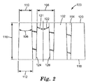
図2はLCF 100の断面図であり、光出射面120及び光入射面118を含む。本明細書では参考として光入射面及び光出射面を記載しているが、使用する際には、本明細書に記載のLCFは見る人又はディスプレイ源のいずれかに面する光出射面を有し得ること、及び光入射面はディスプレイ源又は見る人のいずれかに面し得ることが認識されるであろう。LCF 100は、交互に配置された透過区域102及び吸収区域104を含む。
FIG. 2 is a cross-sectional view of the
LCFフィルムを通る透過量に影響し得る幾何学的パラメーター及び材料特性は多数存在する。それらの中には、(対向する区域の壁に対して透過区域の)壁角106、連続する透過区域のピッチ108(「P」)、及び透過区域の底幅112(「W」)が含まれる。 There are a number of geometric parameters and material properties that can affect the amount of permeation through the LCF film. Among them are the wall angle 106 (of the transmission area relative to the walls of the opposing area), the pitch 108 (“P”) of the continuous transmission area, and the bottom width 112 (“W”) of the transmission area. It is.
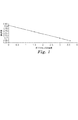
透過区域は、光入射面118から光出射面120までの距離に等しい高さ116(「H」)によっても画定されてよい。LCFは、10°以上など比較的大きい内包壁角106を有することができる。より大きい壁角は光吸収区域の幅を増加させ、それによって垂直入射での透過率を減少させる。垂直入射での光透過率をできる限り大きくできるように、10°未満など、より小さい壁角が好ましい。本明細書に記載のLCFの微細複製に用いられるマスターを作製するために使用可能な工具として、ダイヤモンド工具が想到される。ダイヤモンドの角度の値は、LCFの壁角にほぼ完全に一致するであろう。図1は、LCFの微細複製に用いられたダイヤモンド工具の壁角対そのダイヤモンド工具から作製されたLCFの透過率のプロットを示す。図1によって明らかに示されるように、透過率のレベルはダイヤモンドの角度が最小のときに最高であり、ダイヤモンドの角度が増加するにつれて直線的に減少する。これは、透過区域のより小さい壁角(したがって非透過区域のより小さい壁角でもある)が、LCFからの増加した透過率をもたらすという関係に一致する。
The transmission area may also be defined by a height 116 (“H”) equal to the distance from the
幾つかの実施形態では、本明細書に記載のLCFは、3°以下の内包壁角106を有する。他の実施形態では、内包壁角は、最大で1.5°、1.0°、0.5°、0.3°、0.1°など2°以下である。場合によっては、内包壁角は、実際に0°に等しくてよい。LCFは、連続する非透過区域との第1及び第2境界面をそれぞれ有する透過区域を有するものとして理解されてよい。例えば、図2は第1境界面124及び第2境界面126を示す。第1及び第2境界面は、主視軸からの第1境界角121(θI)及び第2境界角122(θI2)でそれぞれ光出射面120と交差するものとして理解されてよい。本明細書に記載するように、内包壁角106は、対称的及び非対称的な透過区域の境界角に関連してよい。対称的な区域では、第1境界角121(「θI」)及び第2境界角122(「θI2」)は、同一又はほぼ同一の値であろう。非対称的な透過区域では、第1境界角121及び第2境界角122は、異なる値からなるであろう。1つの態様では、1つ又は両方の境界角は、1.5°又は1.5°以下、例えば、1.0°以下、0.8°以下、0.5°以下、0.25°以下、若しくは0.1°以下であってよい。境界角は、0°に等しくてもよい。第1境界角121と第2境界角122との合計は、壁角106の値に等しいと理解されるであろう。より小さい壁角は、より小さいピッチ「P」における、比較的高いアスペクト比(H/W)を有する溝を形成することができ、より低い視角において、より鮮明な画像カットオフを提供することができる。場合によっては、透過区域は、平均高さ116(「H」)及びその最大幅部分における平均幅112(「W」)を有し、H/Wは少なくとも2.0である。場合によっては、H/Wは、少なくとも2.5、3.0、又はそれ以上である。
In some embodiments, the LCF described herein has an included
透過レベルに顕著な悪影響を及ぼさずにプライバシー機能を強化するためには、連続する非透過区域104が高アスペクト比を有し、その一方で連続する透過区域のピッチ108が小さいことが望ましい場合がある。具体的に言うと、ピッチは、0.040mm以下であってよい。更により好ましくは、ピッチは、0.036mm以下であろう。
In order to enhance the privacy function without noticeably adversely affecting the transmission level, it may be desirable for the continuous
より小さい内包壁角106及びより小さいピッチ108により、より低い高さ116(即ち、光入射面から光出射面までのより短い距離)でより高い性能を実現できる。高さは、0.10mm以下であってよい。更により好ましくは、高さは0.080mm未満であるか、0.070mm未満であり得る。
Smaller envelope angles 106 and
透過区域は、最狭区域において平均幅110(「W’」)によっても画定される。LCFが、性能を低下させずにより小さいピッチ及びより小さい壁角を有することが望ましい場合、W’は、W’/Pが0.75を超えるようなピッチPとの関係にあるであろう。更により好ましくは、W’/Pは0.80を超えるか、更には0.090を超え得る。単独で測定されたW’は、好ましくは0.030mm未満であろう。 The transmission area is also defined by the average width 110 (“W ′”) in the narrowest area. If it is desired that the LCF have a smaller pitch and a smaller wall angle without degrading performance, W 'will be in relation to the pitch P such that W' / P is greater than 0.75. Even more preferably, W '/ P may be greater than 0.80 or even greater than 0.090. The measured W 'alone will preferably be less than 0.030 mm.
本明細書に記載の本発明は、所望のLCFの特性に応じて、光入射面又は光出射面のいずれかにおいて、最狭区域において幅110(W’)を有してよい。それに応じて、最大区域における幅Wは、光入射面又は光出射面(W’の対向面にあるかどうかにかかわらず)のいずれかに同様に配置されてよい。したがって、光出射面における幅WO(例えば、110)及び光入射面における幅WI(例えば、112)を画定することが望ましい場合がある。2つの面における幅が、[WO−WI]の絶対値でHを除した値が40を超えるように、透過区域の高さ(つまり、一般にLCFの高さ)との関係を満たすことが望ましい。更に好ましくは、H/[WO−WI]の絶対値は50を超える、又は更により好ましくは60を超えるであろう。 The invention described herein may have a width 110 (W ′) in the narrowest area on either the light entrance surface or the light exit surface, depending on the desired LCF characteristics. Accordingly, the width W in the maximum area may be similarly arranged on either the light incident surface or the light exit surface (whether or not it is on the opposite surface of W ′). Accordingly, it may be desirable to define a width W O (eg, 110) at the light exit surface and a width W I (eg, 112) at the light entrance surface. Satisfy the relationship with the height of the transmission area (that is, generally the height of the LCF) so that the width of the two faces exceeds 40 by dividing H by the absolute value of [W O −W I ]. Is desirable. More preferably, the absolute value of H / [W O -W I ] will be greater than 50, or even more preferably greater than 60.
本明細書に記載のLCFは、任意の望ましい極視野カットオフ角を有するように作製され得る。1つの態様では、極視野カットオフ角は、30°〜90°の範囲、又はそれ以上である。極視野カットオフ角ΦPは、同一所有者の出願PCT/US08/85889号に記載されるように、内部視野カットオフ角「θInt」、「H」、「W」、「P」のパラメーター、及びLCF材料の屈折率を使用して決定できる。 The LCF described herein can be made to have any desired polar field cutoff angle. In one aspect, the polar field cutoff angle is in the range of 30 ° to 90 ° or more. The polar viewing cutoff angle Φ P is a parameter of the internal viewing cutoff angles “θ Int ”, “H”, “W”, “P” as described in the same application PCT / US08 / 85889. , And the refractive index of the LCF material.
場合によっては、極視野カットオフ角よりも大きい角度でLCFを通って透過される光を含む「有効極視野角」(EPVA)を画定することも有用であり得る。例えば、内部視野カットオフ角ΦIntよりも若干大きい角度で非透過区域を遮断する光は、非透過区域の最も薄い部分から「漏れ出す」(即ち、非透過区域の上部及び下部を通って部分的に透過する)可能性がある。更に、LCFの平面に垂直に進む光は、散乱する及び有効極視野角の外側にそれることがある。本明細書で使用するとき、有効極視野角は、相対輝度比が5%以下まで低下する角度として定義される。相対輝度比は、LCFを通して測定した場合の拡散光源の輝度の、LCFなしで測定した場合の同じ拡散光源の輝度に対する比である(パーセンテージとして表される)。本明細書に記載のLCFについては、光は、主視軸方向で65以上の最大相対輝度比(RBR)を有する光出射面を出射する。LCFは、45°以下のEPVAも有する。より好ましくは、LCFは、35°以下のEPVAを有する。 In some cases, it may be useful to define an “effective polar viewing angle” (EPVA) that includes light that is transmitted through the LCF at an angle that is greater than the polar viewing cutoff angle. For example, light that blocks a non-transmissive area at an angle slightly larger than the internal field cutoff angle Φ Int “leaks” from the thinnest part of the non-transmissive area (ie, passes through the top and bottom of the non-transmissive area May be transparent). Furthermore, light traveling perpendicular to the plane of the LCF can scatter and deviate outside the effective polar viewing angle. As used herein, the effective polar viewing angle is defined as the angle at which the relative luminance ratio decreases to 5% or less. The relative luminance ratio is the ratio (expressed as a percentage) of the luminance of the diffuse light source as measured through LCF to the luminance of the same diffuse light source as measured without LCF. For the LCF described herein, light exits a light exit surface having a maximum relative luminance ratio (RBR) of 65 or greater in the main visual axis direction. The LCF also has an EPVA of 45 ° or less. More preferably, the LCF has an EPVA of 35 ° or less.
「機能的極視野角」という用語も当該技術分野において使用されており、同様に極視野カットオフよりも大きい角度でLCFを通って透過される光を含む。機能的極視野角は、LCFを備えるディスプレイの輝度が、LCFを備えるディスプレイの軸輝度の小さなパーセンテージ(例えば、10%、5%、又はそれ以下)まで低下する角度として定義される。しかしながら、このような視野角の定義は、ディスプレイに左右されることがある。 The term “functional polar viewing angle” is also used in the art and includes light that is transmitted through the LCF at an angle that is also greater than the polar field cutoff. Functional polar viewing angle is defined as the angle at which the brightness of a display with LCF drops to a small percentage (eg, 10%, 5%, or less) of the axial brightness of a display with LCF. However, such definition of the viewing angle may depend on the display.
LCFの非透過区域の光吸収材料は、少なくとも可視スペクトルの一部で光を吸収又は遮断するように機能する任意の好適な材料であってよい。幾つかの実施形態では、光吸収材料は、光透過性フィルムの溝又はくぼみにコーティングされるか、ないしは別の方法で提供されて、非透過区域を形成することができる。更なる実施形態では、光吸収材料は、カーボンブラックなどの黒色着色剤を含むことができる。カーボンブラックは、10マイクロメートル未満、例えば1マイクロメートル以下の粒径を有する粒状カーボンブラックであってよい。カーボンブラックは、いくつかの実施形態では、1マイクロメートル未満の平均粒径を有してよい。更に別の実施形態では、吸収材料(例えば、カーボンブラック、別の顔料若しくは染料又はこれらの組み合わせ)は、好適な結合剤に分散され得る。光吸収材料には、光が非透過区域を通って透過されるのを遮断するように機能することができる粒子又は他の散乱要素も挙げられる。 The light absorbing material in the non-transmissive area of the LCF may be any suitable material that functions to absorb or block light at least in part of the visible spectrum. In some embodiments, the light-absorbing material can be coated in grooves or indentations in the light transmissive film or otherwise provided to form non-transmissive areas. In a further embodiment, the light absorbing material can include a black colorant such as carbon black. The carbon black may be a granular carbon black having a particle size of less than 10 micrometers, for example 1 micrometer or less. The carbon black may have an average particle size of less than 1 micrometer in some embodiments. In yet another embodiment, the absorbent material (eg, carbon black, another pigment or dye, or combinations thereof) can be dispersed in a suitable binder. Light absorbing materials also include particles or other scattering elements that can function to block light from being transmitted through non-transmissive areas.
光透過区域/非透過区域の境界面における反射は、スペクトル、例えば人間の可視スペクトルの少なくとも一部における光透過性材料の相対屈折率及び非透過材料の屈折率によって制御できる。場合によっては、矯正後の透過区域の屈折率(N1)は、非透過区域の屈折率(N2)よりも約0.005未満だけ大きい。このような場合、屈折率差(N2−N1)は−0.005未満ではない。つまり、(N2−N1)は−0.005以上である。別の場合では、一致しない透過区域の屈折率N1及び非透過区域の屈折率N2を有することが望ましいことがある。これは、例えば、非画像光がフィルムを通過する時など全反射が望まれる場合に望ましいことがある。かかる用途の例には、透過型LCDのバックライトコンポーネントとして本明細書に記載のLCFを提供することが挙げられ、この場合LCFは、光が撮像透過型LCDを通過する前に光源光をコリメートするように機能する。 Reflection at the interface of the light transmissive / non-transmissive area can be controlled by the relative refractive index of the light transmissive material and the refractive index of the non-transmissive material in at least a portion of the spectrum, eg, the human visible spectrum. In some cases, the refractive index (N1) of the transmissive area after correction is greater by less than about 0.005 than the refractive index (N2) of the non-transmissive area. In such a case, the refractive index difference (N2-N1) is not less than -0.005. That is, (N2-N1) is -0.005 or more. In other cases, it may be desirable to have a refractive index N1 for the transmissive zone and a refractive index N2 for the non-transmissive zone that do not match. This may be desirable when total reflection is desired, for example when non-image light passes through the film. Examples of such applications include providing the LCF described herein as a backlight component of a transmissive LCD, where the LCF collimates the source light before the light passes through the imaging transmissive LCD. To function.
本明細書に記載のLCFは、複数個の非透過区域を含む。いくつかの実施形態では、非透過区域は、本明細書の他の部分に示されるように複数個のチャネルであり得る。場合によっては、本明細書に記載のLCFは、米国特許第6,398,370号(Chiuら)に記載されているように、第2 LCFと組み合わせることができる。 The LCF described herein includes a plurality of non-transmissive areas. In some embodiments, the non-transmissive area can be a plurality of channels as shown elsewhere herein. In some cases, the LCF described herein can be combined with a second LCF, as described in US Pat. No. 6,398,370 (Chiu et al.).
重合性樹脂は、(メタ)アクリレートモノマー、(メタ)アクリレートオリゴマー、及びこれらの混合物から選択される第1重合性成分及び第2重合性成分の組み合わせを含んでよい。本明細書で使用するとき、「モノマー」又は「オリゴマー」は、ポリマーに変換できる任意の物質である。用語「(メタ)アクリレート」は、アクリレート及びメタクリレート化合物の両方を指す。場合によっては、重合性組成物は、(メタ)アクリレート化ウレタンオリゴマー、(メタ)アクリレート化エポキシオリゴマー、(メタ)アクリレート化ポリエステルオリゴマー、(メタ)アクリレート化フェノールオリゴマー、(メタ)アクリレート化アクリルオリゴマー、及びこれらの混合物を含んでよい。重合性樹脂は、紫外線硬化性樹脂などの放射線硬化性ポリマー樹脂であってよい。場合によっては、本説明のLCFに有用な重合性樹脂組成物は、米国特許出願公開第2007/0160811号(Gaidesら)に記載されている重合性樹脂組成物などの重合性樹脂組成物をこれらの組成物が本明細書に記載の屈折率及び吸収特性を満たす程度まで含んでよい。 The polymerizable resin may comprise a combination of a first polymerizable component and a second polymerizable component selected from (meth) acrylate monomers, (meth) acrylate oligomers, and mixtures thereof. As used herein, a “monomer” or “oligomer” is any substance that can be converted to a polymer. The term “(meth) acrylate” refers to both acrylate and methacrylate compounds. In some cases, the polymerizable composition comprises (meth) acrylated urethane oligomer, (meth) acrylated epoxy oligomer, (meth) acrylated polyester oligomer, (meth) acrylated phenol oligomer, (meth) acrylated acrylic oligomer, And mixtures thereof. The polymerizable resin may be a radiation curable polymer resin such as an ultraviolet curable resin. In some cases, the polymerizable resin compositions useful for the LCFs described herein include those polymerizable resin compositions such as those described in US Patent Application Publication No. 2007/0160811 (Gides et al.). To the extent that the composition satisfies the refractive index and absorption characteristics described herein.
微細構造保有物品は、(a)重合性組成物を調製する工程と、(b)マスターのキャビティを満たすためにかろうじて十分な量でマスターネガ微細構造成型表面上に重合性組成物を付着させる工程と、(c)予成形させたベースとマスター(少なくとも一方は可撓性である)との間で重合性組成物のビードを移動させることによりキャビティを満たす工程と、(d)組成物を硬化させる工程と、が含まれる方法によって調製できる。その付着温度は、周囲温度〜約180°F(82℃)の範囲であり得る。マスターは、ニッケル、クロムメッキ銅、ニッケルメッキ銅、若しくは黄銅のような金属製であってよく、又は重合条件下で安定であり、かつマスターから重合材料をきれいに取り出すことができる表面エネルギーを有する熱可塑性材料であってもよい。ベースへの光学層の接着を促進するために、ベースフィルムの1つ以上の表面に、任意に下地処理又は他の処理を施すことができる。 The microstructured article comprises: (a) preparing a polymerizable composition; and (b) depositing the polymerizable composition on the master negative microstructured molding surface in a barely sufficient amount to fill the master cavity. And (c) filling the cavity by moving a bead of polymerizable composition between a preformed base and a master (at least one of which is flexible); and (d) curing the composition. And a step comprising the steps of: The deposition temperature can range from ambient temperature to about 180 ° F. (82 ° C.). The master may be made of a metal such as nickel, chrome-plated copper, nickel-plated copper, or brass, or heat that has a surface energy that is stable under polymerization conditions and that allows the polymeric material to be removed cleanly from the master. It may be a plastic material. In order to promote adhesion of the optical layer to the base, one or more surfaces of the base film can optionally be subjected to a base treatment or other treatment.
マスターネガは、高アスペクト比のダイヤモンド工具を用いて形成されてよい。例えば、ダイヤモンド工具は、ねじ研削プロセスによるマスターの切削又は形成に用いられてよい。らせんチャネルを切るために、マスターを回転させながらダイヤモンド工具を水平方向に前進させるねじ切削プロセスは、短時間で切削できるために、ダイヤモンドがマスター材料の隣接区画に連続して挿入されるプランジ切削よりも好ましい場合がある。より薄い製品構造、原価低減、及び正確な寸法を可能にする、LCFの所望の小さい区域角及び低ピッチを達成するために、LCFの複製に用いられるマスターは、高アスペクト比及び正確な寸法を備える工具によって形成される必要がある。かかる工具の使用は、最終的に向上したLCFの寸法の精度をもたらす。更に、工具は、成形された溝及び工具自体の両方のより低い変形性をもたらす滑らかな仕上がりを有する。1つの実施形態では、工具はダイヤモンド工具であろう。 The master negative may be formed using a high aspect ratio diamond tool. For example, a diamond tool may be used for cutting or forming a master by a thread grinding process. The thread cutting process, in which the diamond tool is advanced horizontally while rotating the master to cut the helical channel, is faster than the plunge cutting where diamonds are inserted continuously into adjacent sections of the master material because of the short cutting time. May also be preferred. In order to achieve the desired small area angle and low pitch of the LCF, which enables thinner product structure, cost reduction, and accurate dimensions, the master used for LCF replication has high aspect ratio and accurate dimensions. It must be formed by the tool provided. The use of such tools ultimately results in improved LCF dimensional accuracy. Furthermore, the tool has a smooth finish that results in lower deformability of both the shaped groove and the tool itself. In one embodiment, the tool will be a diamond tool.
所望のアスペクト比、寸法、及び平滑度を備えるダイヤモンド工具を製造するためには、好ましくは特定のプロセスが用いられるであろう。図3は、かかるプロセスを説明するフローチャートを提供する。このプロセスは、2つの小平面を有するV字形のダイヤモンドを使用して開始する。典型的な角度は15〜90°の範囲であってよい。次に、ダイヤモンドの頂点をラッピングして、大きい逃げ角(例えば、30°)を有する平面を作製する。この平面は、完成時の最終工具先端幅の目標値よりも若干大きい寸法(10〜20um)であるべきである。あるいは、このプロセスは、2つの頂点の上に形成された平面を既に有するダイヤモンドを使用して開始してもよい。次に、砥石車又はスカイフの縁部を用いて、ダイヤモンドの第1小平面を研削することにより迅速に材料を除去する。この工程に続いて、研削又はスカイフ研磨によりダイヤモンドのもう一方の小平面から材料を除去する。研削工程に好適な工具の1つは、精密ラッピング/研削機械へと改良した、Nanoform 200ダイヤモンド旋盤である。回転ラップは、平面の下に柱状構造体が形成されるまで各小平面を平行に突き進む。この工程の後に、平面は、完了時の最終目標平面幅(即ち、1〜5umの範囲)に更に近付くべきである。最終的に、柱状構造体は、集束イオンビームミリングプロセスでミリング加工する。イオンミリングプロセスは構造体を完成させて、切端に滑らかな仕上がりをもたらす。完成した柱は、高アスペクト比と、側壁間の小さい角度と、を有するであろう。ダイヤモンド工具で切削した任意のマスターネガ及びマスターネガによって微細複製されたLCFも、小さい壁角、高アスペクト比、及び滑らかな仕上がりを示すべきである。 In order to produce a diamond tool with the desired aspect ratio, dimensions, and smoothness, a specific process will preferably be used. FIG. 3 provides a flowchart illustrating such a process. The process begins with a V-shaped diamond having two facets. A typical angle may be in the range of 15-90 °. Next, the top of the diamond is wrapped to produce a plane having a large clearance angle (eg, 30 °). This plane should be a dimension (10-20 um) slightly larger than the target value of the final tool tip width at completion. Alternatively, the process may begin using a diamond that already has a plane formed on the two vertices. The material is then rapidly removed by grinding the first facet of diamond using the edge of a grinding wheel or skyf. Following this step, material is removed from the other facet of the diamond by grinding or skiff polishing. One suitable tool for the grinding process is a Nanoform 200 diamond lathe, modified to a precision lapping / grinding machine. The rotating lap pierces each small plane in parallel until a columnar structure is formed below the plane. After this step, the plane should be closer to the final target plane width at completion (ie, in the range of 1-5 um). Finally, the columnar structure is milled by a focused ion beam milling process. The ion milling process completes the structure and provides a smooth finish at the cut edge. The finished pillar will have a high aspect ratio and a small angle between the sidewalls. Any master negative cut with a diamond tool and LCF microreplicated with a master negative should also exhibit small wall angles, high aspect ratios, and a smooth finish.
ダイヤモンドの一般的形状は、レーザー切断など他の方法によって余分なダイヤモンド材料を切除することにより達成され得ることを理解されたい。 It should be understood that the general shape of diamond can be achieved by cutting away excess diamond material by other methods such as laser cutting.
本明細書に記載の重合性樹脂組成物は、例えば、輝度上昇フィルムなどが挙げられる他の光透過性物品及び/又は微細構造物品の製造に用いるのに好適である。「微細構造」という用語は、米国特許第4,576,850号(Martens)に定義及び説明されたように、本明細書で使用される。微細構造は、例えば中心線の上の表面輪郭により包囲された面積の合計が線の下の面積の合計と等しくなるように、微細構造を通って引かれた平均中心線から輪郭がずれている物品表面内の突起及びくぼみのように、一般に不連続であり、線は物品の名目表面(微細構造を有する)に本質的に平行である。例えば1〜30cmの表面の典型的な代表長さを通って、光学又は電子顕微鏡により測定したとき、ずれの高さは典型的には、約±0.005〜±750マイクロメートルである。平均中心線は、平面、凹部、凸部、非球面、又はこれらの組み合わせであることができる。ずれが低位、例えば、±0.005、±0.1又は±0.05マイクロメートルであり、かつ、ずれがめったに起こらないか又は最小限に抑えられている、即ち、表面が任意の著しい不連続を含まない物品は、本質的に「平坦な」又は「滑らかな」表面を有すると見なすことができる。他の物品は、例えば、±0.1〜±750マイクロメートルの高位であり、並びに同じ又は異なる、及び、ランダム若しくは規則正しい方式により相隔たる又は連続する複数個の実利的不連続を含む微細構造に起因するずれを有する。 The polymerizable resin composition described in the present specification is suitable for use in the production of other light-transmitting articles and / or microstructured articles such as a brightness enhancement film. The term “microstructure” is used herein as defined and explained in US Pat. No. 4,576,850 (Martens). The microstructure is deviated from the average centerline drawn through the microstructure, for example, so that the total area enclosed by the surface contour above the centerline is equal to the total area under the line Like protrusions and indentations in the article surface, they are generally discontinuous and the lines are essentially parallel to the nominal surface (having the microstructure) of the article. For example, when measured with an optical or electron microscope through a typical representative length of a surface of 1-30 cm, the height of the deviation is typically about ± 0.005- ± 750 micrometers. The average center line can be a plane, a recess, a protrusion, an aspheric surface, or a combination thereof. The deviation is low, for example ± 0.005, ± 0.1 or ± 0.05 micrometers and the deviation rarely occurs or is minimized, i.e. the surface has any significant imperfections. Articles that do not include a continuum can be considered to have an essentially “flat” or “smooth” surface. Other articles are, for example, as high as ± 0.1 to ± 750 micrometers, and in microstructures that contain a plurality of practical discontinuities that are the same or different and spaced or continuous in a random or regular manner. There is a deviation caused by it.
本明細書に記載の光制御フィルムは、ベース基材層、偏光若しくは非偏光フィルム、ポリカーボネートフィルム若しくは基材、及び相互作用する光の光学特性、又はフィルムの材料若しくは機械的特性に望ましい影響を及ぼす任意の他の種類のフィルムと共に用いられてよいことを理解されたい。薄層及び接着剤も、かかるフィルム積層体の一部を形成してよい。例えば、光学カバーフィルムは、光制御フィルム(LCFの光出力側)に貼り付けられてよい。この光学カバーフィルムは、ベース基材層と同一の材料であっても、異なる材料であってもよい。光学カバーフィルム又はベース基材層の材料には、例えば、市販のポリカーボネートフィルムが挙げられてよい。無光沢仕上げ又は光沢仕上げを提供するように、特定のポリカーボネート材料を選択してもよい。任意のカバーフィルムは、接着剤で微細構造表面に接着できる。かかる接着剤は、紫外線硬化性アクリル酸系接着剤、転写接着剤などの光学的に透明な任意の接着剤でよい。 The light control film described herein has a desirable effect on the optical properties of the base substrate layer, polarized or non-polarized film, polycarbonate film or substrate, and interacting light, or the material or mechanical properties of the film. It should be understood that it may be used with any other type of film. Thin layers and adhesives may also form part of such film laminates. For example, the optical cover film may be attached to a light control film (light output side of the LCF). This optical cover film may be the same material as the base substrate layer or a different material. Examples of the material for the optical cover film or the base substrate layer may include a commercially available polycarbonate film. A particular polycarbonate material may be selected to provide a matte finish or a glossy finish. Any cover film can be adhered to the microstructured surface with an adhesive. Such an adhesive may be any optically transparent adhesive such as an ultraviolet curable acrylic adhesive or a transfer adhesive.
本明細書の目的では、光入射面から光出射面までの距離、つまり高さHは、LCF自体の両面からの距離であることを理解されたい。使用され得るフィルム積層体の高さはHを超えてよいが、本説明の目的ではLCFの高さの一部とは見なされない。この理解によると、LCFの光入射面は、LCFと接触する任意の他の基材又はフィルムではなく、LCF自体に光が入射する場所である。光出射面は、LCFと接触する任意の他の基材又はフィルムではなく、LCF自体から光が出射する場所である。 For purposes of this specification, it should be understood that the distance from the light entrance surface to the light exit surface, ie, the height H, is the distance from both sides of the LCF itself. The height of the film laminate that can be used may exceed H, but is not considered part of the LCF height for purposes of this description. According to this understanding, the light entrance surface of the LCF is where the light enters the LCF itself, rather than any other substrate or film in contact with the LCF. The light exit surface is where the light exits from the LCF itself, rather than any other substrate or film that contacts the LCF.
化学組成及びベース材料の厚みは、構築している製品の要件によって異なり得る。つまり、強度、透明性、光遅延特性、耐温度性、表面エネルギー、光学層などへの接着性に対するニーズのバランスを取る。場合によっては、ベース層の厚みは、少なくとも約0.025ミリメートル(mm)であり、約0.1mm〜約0.5mmであってよい。 The chemical composition and base material thickness may vary depending on the requirements of the product being constructed. In other words, it balances the needs for strength, transparency, light delay characteristics, temperature resistance, surface energy, adhesion to optical layers, and the like. In some cases, the thickness of the base layer is at least about 0.025 millimeters (mm) and can be from about 0.1 mm to about 0.5 mm.
有用なベース材料には、例えばスチレン−アクリロニトリル、酢酸セルロースブチレート、酢酸セルロースプロピオネート、セルローストリアセテート、ポリエーテルスルホン、ポリメチルメタクリレート、ポリウレタン、ポリエステル、ポリカーボネート、ポリ塩化ビニル、ポリスチレン、ポリエチレンナフタレート、ナフタレンジカルボン酸に基づくコポリマー又はブレンド、ポリオレフィン系材料、例えばポリエチレン、ポリプロピレン及びポリクロロオレフィンのキャスト又は配向フィルム、ポリイミド、並びにガラスが挙げられる。所望により、ベース材料には、これらの材料の混合物又は組み合わせを含有させることができる。ある場合には、ベースは多層であってもよいし、又は連続相の中に懸濁又は分散した分散成分を含有してもよい。 Useful base materials include, for example, styrene-acrylonitrile, cellulose acetate butyrate, cellulose acetate propionate, cellulose triacetate, polyethersulfone, polymethyl methacrylate, polyurethane, polyester, polycarbonate, polyvinyl chloride, polystyrene, polyethylene naphthalate, Copolymers or blends based on naphthalene dicarboxylic acids, polyolefin-based materials such as polyethylene, polypropylene and polychloroolefin cast or oriented films, polyimides, and glass. If desired, the base material can contain a mixture or combination of these materials. In some cases, the base may be multi-layered or may contain dispersed components suspended or dispersed in a continuous phase.
1つの態様では、ベース材料の例には、ポリエチレンテレフタレート(PET)及びポリカーボネート(PC)が挙げられる。有用なPETフィルムの例には、商品名「Melinex 618」でDuPont Films(Wilmington,Delaware)から入手可能なフォトグレードポリエチレンテレフタレートが挙げられる。光学グレードポリカーボネートフィルムの例には、GE Polymershapes(Seattle,WA)から入手可能なLEXAN(登録商標)ポリカーボネートフィルム8010、Teijin Kasei(Alpharetta,GA)から入手可能なPanlite 1151が挙げられる。 In one aspect, examples of base materials include polyethylene terephthalate (PET) and polycarbonate (PC). Examples of useful PET films include photograde polyethylene terephthalate available from DuPont Films (Wilmington, Del.) Under the trade designation “Melinex 618”. Examples of optical grade polycarbonate films include LEXAN® polycarbonate film 8010 available from GE Polymershapes (Seattle, WA) and Panlite 1151 available from Teijin Kasei (Alphattata, GA).
いくつかのベース材料は、光学的に活性であり得、偏光材料として機能することができる。多くのベースはまた、本明細書においてフィルム又は基材とも呼ばれ、光学製品分野において、偏光材料として有用であることが既知である。フィルムを通過する光の偏光は、例えば、通過光を選択的に吸収するフィルム材料中に二色偏光子を含ませることによって実現することができる。光の偏光はまた、配列雲母チップのような無機材料を含ませることによって、又は、連続フィルム中に分散する光変調液晶の液滴のような、連続フィルム中に分散する不連続相によって実現することができる。代替手段として、異なる材料のマイクロファイン層からフィルムを調製することができる。フィルム内の偏光材料は、例えば、フィルムの延伸、電場又は磁場の印加、及び、コーティング技術のような方法を利用することによって、偏光配向に揃えることができる。 Some base materials can be optically active and can function as polarizing materials. Many bases are also referred to herein as films or substrates and are known to be useful as polarizing materials in the field of optical products. Polarization of light passing through the film can be achieved, for example, by including a dichroic polarizer in the film material that selectively absorbs the passing light. The polarization of light is also achieved by including an inorganic material such as an arrayed mica chip or by a discontinuous phase dispersed in a continuous film, such as droplets of light-modulated liquid crystals dispersed in the continuous film. be able to. As an alternative, films can be prepared from microfine layers of different materials. The polarizing material in the film can be aligned with the polarization orientation by utilizing methods such as stretching the film, applying an electric or magnetic field, and coating techniques, for example.
本明細書に記載のベース材料は排他的なものではない。また、当業者に理解されるように、他の偏光フィルム及び非偏光フィルムもまた、本説明の光学製品用ベースとして有用であり得る。これらのベース材料は、多層構造体を形成するために、例えば偏光フィルムが挙げられる任意の数の他のフィルムと組み合わせることができる。特定のベースの厚さはまた、光学製品の所望の特性によって異なり得る。 The base materials described herein are not exclusive. Also, as will be appreciated by those skilled in the art, other polarizing and non-polarizing films may also be useful as the base for the optical products described herein. These base materials can be combined with any number of other films, including for example polarizing films, to form a multilayer structure. The particular base thickness may also vary depending on the desired properties of the optical product.
全体を通して記載するように、本明細書に記載のLCFは、非透過区域の方向に対して垂直な方向でプライバシー機能を提供できる視野カットオフ角を提供する。このことは、プライバシー用途において有益であり得るが、例えば、プラズマディスプレイパネルのコントラスト促進及び自動車用途の光コリメーティング特性においても有用であり得る。具体的には、多くの自動車の計器パネルは、照光ディスプレイ、例えば、液晶ディスプレイ(LCD)を提供する。しかしながら、このようなディスプレイからの光は、フロントガラスから反射して、運転者又は同乗者の気を散らすか、あるいは視界を遮ることがある。本明細書に記載のLCFの一部は、垂直方向の光を遮断することで、このようなフロントガラスの反射を軽減させることがある。 As described throughout, the LCF described herein provides a viewing cutoff angle that can provide a privacy function in a direction perpendicular to the direction of the non-transmissive area. This can be beneficial in privacy applications, but can also be useful, for example, in contrast enhancement of plasma display panels and light collimating properties in automotive applications. Specifically, many automotive instrument panels provide illuminated displays, such as liquid crystal displays (LCDs). However, the light from such a display may reflect off the windshield and distract the driver or passenger or obstruct the field of view. Some of the LCFs described herein may reduce such windshield reflections by blocking vertical light.
場合によっては、非透過区域の方向に平行な方向でより多くの光を感知できることは有益である。例えば、上述した自動車用途では、フロントガラスから反射する光量を制限しながら、運転者及び同乗者にディスプレイパネルを読む際に最大輝度を提供することは有益であり得る。本説明の幾つかの実施形態では、本明細書に記載のLCFは、より多くの光をルーバーの方向にLCFを通して透過することができる(ルーバーの方向とは、設置時にこれが垂直方向又は水平方向を表すのかにかかわらず、非透過区域の方向に平行な方向を意味する)。これは、垂線から±20°の範囲にわたって、ルーバー(非透過区域)に平行な方向で測定される最小RBR値として表すことができる(以降はMB20と呼ぶ)。本明細書に記載のLCFの幾つかの実施形態では、LCFは、60以上、例えば、62以上、更には64以上のMB20を有する。 In some cases, it is beneficial to be able to sense more light in a direction parallel to the direction of the non-transmissive area. For example, in the automotive applications described above, it may be beneficial to provide maximum brightness when reading the display panel to the driver and passengers while limiting the amount of light reflected from the windshield. In some embodiments of the present description, the LCF described herein can transmit more light through the LCF in the direction of the louver (the direction of the louver is the vertical or horizontal direction when installed). Means the direction parallel to the direction of the non-transparent area. This can be expressed as the minimum RBR value measured in the direction parallel to the louver (non-transmission zone) over a range of ± 20 ° from the normal (hereinafter referred to as MB20). In some embodiments of the LCF described herein, the LCF has 60 or more, such as 62 or more, and even 64 or more MB20.
ピクセルモアレ
一般に、プライバシーフィルタはバイアス角で変換されて、目に見えるモアレを低減又は排除する。この方法の1つの欠点は、ウェブ方向に対してある角度をなす切断部は収量を減少させ、その部分がディスプレイで用いられると、見る人に不均一な輝度プロファイルを与え得ることである。本発明における連続する透過区域のより低いピッチは、著しいバイアス角を必要とせずにより少ないモアレをもたらすか、全くモアレをもたらさない。より小さいバイアス角により、見る人により高い輝度が向けられることができる。これは、例えば、ディスプレイを見る運転者により高い輝度をもたらすことが望ましいが、フロントガラスのグレアを生じさせる軸外光の量を低減させることも望ましい、上述した自動車の例において有益である。本明細書に記載の光制御フィルムの効果の1つは、より小さい、又は更には0°であり得るバイアス角を使用して、モアレを低減又は排除できることである。
Pixel Moire Generally, privacy filters are transformed with a bias angle to reduce or eliminate visible moire. One drawback of this method is that cuts that are at an angle to the web direction reduce yield, and when that part is used in a display, it can give the viewer a non-uniform brightness profile. The lower pitch of the continuous transmission areas in the present invention does not require a significant bias angle and results in less moiré or no moiré. With a smaller bias angle, higher brightness can be directed to the viewer. This is beneficial, for example, in the automobile example described above, where it is desirable to provide higher brightness to the driver viewing the display, but it is also desirable to reduce the amount of off-axis light that causes windshield glare. One of the effects of the light control film described herein is that a moiré can be reduced or eliminated using a bias angle that can be smaller or even 0 °.
記載のLCFのピクセルモアレ低減機能の測定を行った。測定は、様々なピクセルピッチを有する様々な異なるディスプレイ(モニタ、ノートパソコン、及び携帯型)を使用したときのモアレパターンを人が定性的に観察することによって行った。LCFをディスプレイ上に配置し、バイアス角0°から、モアレ効果が目で見て分からなくなるバイアスまで回転させた。モアレ干渉レベルの強度は、LCFをバイアス角0°からモアレが消滅するバイアス角まで回転させるにつれて異なったが、この角度を超えるとモアレは観察されなかった。 The pixel moire reduction function of the described LCF was measured. Measurements were made by a person qualitatively observing the moire pattern when using a variety of different displays (monitors, laptops, and portables) with different pixel pitches. The LCF was placed on the display and rotated from a bias angle of 0 ° to a bias where the moire effect was not visible. The intensity of the moire interference level varied as the LCF was rotated from a bias angle of 0 ° to a bias angle at which the moire disappeared, but no moire was observed beyond this angle.

表内のLCFに付随する値は、連続する透過区域のピッチを表す。最小ピッチを有するLCF試料により、モアレを消滅させるための最小バイアス角を実現できた。 The value associated with LCF in the table represents the pitch of successive transmission areas. With the LCF sample having the minimum pitch, the minimum bias angle for eliminating the moire could be realized.
本説明は、本明細書に記載の特定の実施例に限定されると考えるべきではなく、更に適切に言えば添付の「特許請求の範囲」に相当する本説明の全態様を包含すると理解されるべきである。本明細書を検討すると様々な修正形態、等価の方法、及び本説明を適用できる非常に多くの構造が、本説明が対象とする当業界の技術者には容易に明らかなはずである。 This description should not be construed as limited to the particular embodiments described herein, but is understood to encompass all aspects of this description, more appropriately, corresponding to the appended claims. Should be. Upon review of this specification, numerous modifications, equivalent methods, and numerous structures to which this description can be applied should be readily apparent to those skilled in the art to which this description is directed.
Claims (19)
前記光入射面と前記光出射面との間に交互に配置された透過区域及び非透過区域であって、各透過区域がその最狭区域において幅W’を有する、透過区域及び非透過区域と、を含み、
連続する透過区域の平均ピッチPが0.040mm以下であり、
W’/P>0.75である、光制御フィルム。 A light incident surface, and a light exit surface facing the light incident surface;
Transmissive and non-transmissive areas alternately disposed between the light entrance surface and the light exit surface, each transmissive area having a width W ′ in its narrowest area; and Including,
The average pitch P of the continuous transmission areas is 0.040 mm or less,
A light control film in which W ′ / P> 0.75.
前記光入射面と前記光出射面との間に交互に配置された透過区域及び非透過区域と、を含み、
連続する透過区域の平均ピッチが0.040mm以下であり、
前記光入射面に入射した光が、主視軸方向で65以上の最大相対輝度比(RBR)と、45°以下の有効極視野角(EPVA)と、を有する前記光出射面を出射する、光制御フィルム。 A light incident surface and a light exit surface facing the light incident surface;
Transmissive and non-transmissive areas alternately disposed between the light incident surface and the light exit surface,
The average pitch of the continuous transmission areas is 0.040 mm or less,
The light incident on the light incident surface exits the light emitting surface having a maximum relative luminance ratio (RBR) of 65 or more in the main visual axis direction and an effective polar viewing angle (EPVA) of 45 ° or less. Light control film.
前記光入射面と前記光出射面との間に交互に配置された透過区域及び非透過区域であって、各透過区域が前記出射面における第1幅WOと、前記入射面における第2幅WIと、を有し、各透過区域が前記光入射面から前記光出射面までの距離Hを延在する、透過区域及び非透過区域と、を含み、
(H/│WO−WI│)>40であり、
前記光入射面に入射した光が、主視軸方向で65以上の最大相対輝度比(RBR)と、45°以下の有効極視野角(EPVA)と、を有する前記光出射面を出射する、光制御フィルム。 A light incident surface and a light exit surface facing the light incident surface;
Transmission areas and non-transmission areas alternately arranged between the light incident surface and the light emission surface, each transmission area having a first width W O on the emission surface and a second width on the incident surface. has a W I, and each transmission zone extends a distance H from the light incident surface to said light emitting surface, comprising: a transmission section and a non-transmissive areas, and
(H / │W O -W I │)> 40,
The light incident on the light incident surface exits the light emitting surface having a maximum relative luminance ratio (RBR) of 65 or more in the main visual axis direction and an effective polar viewing angle (EPVA) of 45 ° or less. Light control film.
光入射面、及び前記光入射面に対向する光出射面と、
前記光入射面と前記光出射面との間に交互に配置された透過区域及び非透過区域と、を含み、
各透過区域と各非透過区域との間の第1境界面が、該フィルムの主視軸から測定した第1境界角θIを形成し、前記第1境界角θIが1°以下であり、
前記光入射面に入射した光が、主視軸方向で65以上の最大相対輝度比(RBR)と、45°以下の有効極視野角(EPVA)と、を有する前記光出射面を出射する、光制御フィルム。 A light control film,
A light incident surface and a light exit surface facing the light incident surface;
Transmissive and non-transmissive areas alternately disposed between the light incident surface and the light exit surface,
A first boundary surface between each transmission area and each non-transmission area forms a first boundary angle θ I measured from the main visual axis of the film, and the first boundary angle θ I is 1 ° or less. ,
The light incident on the light incident surface exits the light emitting surface having a maximum relative luminance ratio (RBR) of 65 or more in the main visual axis direction and an effective polar viewing angle (EPVA) of 45 ° or less. Light control film.
前記光入射面と前記光出射面との間に交互に配置された透過区域及び非透過区域と、を含み、
前記光入射面から前記光出射面までの距離が0.080mm未満であり、
前記光入射面に入射した光が、主視軸方向で65以上の最大相対輝度比(RBR)と、45°以下の有効極視野角(EPVA)と、を有する前記光出射面を出射する、光制御フィルム。 A light incident surface and a light exit surface facing the light incident surface;
Transmissive and non-transmissive areas alternately disposed between the light incident surface and the light exit surface,
The distance from the light incident surface to the light emitting surface is less than 0.080 mm,
The light incident on the light incident surface exits the light emitting surface having a maximum relative luminance ratio (RBR) of 65 or more in the main visual axis direction and an effective polar viewing angle (EPVA) of 45 ° or less. Light control film.
V字形のダイヤモンドの上部をラッピングするか、研削して、所定の幅を有する平面を製造する工程と、
前記V字形のダイヤモンドの両方の小平面を研削するか、スカイフ研磨して、前記平面の下に柱状構造体を製造する工程と、
前記柱の縁部をイオンミリングして、滑らかな切端を製造する工程と、を含む、方法。 A method for manufacturing a tool, comprising:
Lapping or grinding the top of the V-shaped diamond to produce a plane having a predetermined width;
Grinding or milling both facets of the V-shaped diamond to produce columnar structures under the plane;
Ion milling the edge of the column to produce a smooth cut edge.
Applications Claiming Priority (3)
| Application Number | Priority Date | Filing Date | Title |
|---|---|---|---|
| US21822809P | 2009-06-18 | 2009-06-18 | |
| US61/218,228 | 2009-06-18 | ||
| PCT/US2010/038815 WO2010148082A2 (en) | 2009-06-18 | 2010-06-16 | Light control film |
Publications (2)
| Publication Number | Publication Date |
|---|---|
| JP2012530938A true JP2012530938A (en) | 2012-12-06 |
| JP2012530938A5 JP2012530938A5 (en) | 2013-07-25 |
Family
ID=43357028
Family Applications (1)
| Application Number | Title | Priority Date | Filing Date |
|---|---|---|---|
| JP2012516237A Pending JP2012530938A (en) | 2009-06-18 | 2010-06-16 | Light control film |
Country Status (7)
| Country | Link |
|---|---|
| US (2) | US9063284B2 (en) |
| EP (1) | EP2443492A4 (en) |
| JP (1) | JP2012530938A (en) |
| KR (1) | KR101714807B1 (en) |
| CN (2) | CN102460239A (en) |
| TW (1) | TWI570446B (en) |
| WO (1) | WO2010148082A2 (en) |
Cited By (2)
| Publication number | Priority date | Publication date | Assignee | Title |
|---|---|---|---|---|
| US11256125B2 (en) | 2015-02-16 | 2022-02-22 | Dai Nippon Printing Co., Ltd. | Optical sheet, image source unit and image display device |
| US11635562B2 (en) | 2015-02-16 | 2023-04-25 | Dai Nippon Printing Co., Ltd. | Image source unit, and liquid crystal display device |
Families Citing this family (18)
| Publication number | Priority date | Publication date | Assignee | Title |
|---|---|---|---|---|
| WO2010090924A2 (en) | 2009-02-06 | 2010-08-12 | 3M Innovative Properties Company | Light control film and multi-layer optical film stack |
| US9041885B2 (en) | 2010-06-10 | 2015-05-26 | 3M Innovative Properties Company | Display device and method of LC panel protection |
| US10185058B2 (en) | 2013-07-01 | 2019-01-22 | 3M Innovative Properties Company | Protection film suitable for illuminated display devices |
| KR102414650B1 (en) * | 2014-06-30 | 2022-06-30 | 쓰리엠 이노베이티브 프로퍼티즈 캄파니 | 360 degree privacy film |
| US20160124126A1 (en) * | 2014-10-29 | 2016-05-05 | Sergiy Vasylyev | Angular selective light control sheeting and method of making the same |
| US10489613B2 (en) | 2017-11-15 | 2019-11-26 | Dell Products L.P. | System and method of controlling light emissions of displays |
| JP7358356B2 (en) * | 2017-12-13 | 2023-10-10 | スリーエム イノベイティブ プロパティズ カンパニー | High transmittance light control film |
| CN111465894A (en) | 2017-12-13 | 2020-07-28 | 3M创新有限公司 | High transmittance light control film |
| KR102496169B1 (en) | 2017-12-13 | 2023-02-03 | 엘지디스플레이 주식회사 | Viewing angle control film and liquid crystal display device including the same |
| US20190189062A1 (en) * | 2017-12-19 | 2019-06-20 | Dell Products L.P. | System and Method of Controlling Light Emissions of Displays |
| US11086129B2 (en) * | 2018-02-21 | 2021-08-10 | Valve Corporation | Head-mounted display with narrow angle backlight |
| US10684507B2 (en) | 2018-03-19 | 2020-06-16 | Dell Products L.P. | System and method of controlling light emissions of displays |
| CN110596799A (en) * | 2018-06-13 | 2019-12-20 | 夏普株式会社 | Viewing angle control sheet and method for manufacturing viewing angle control sheet |
| US11668977B2 (en) | 2018-12-14 | 2023-06-06 | 3M Innovative Properties Company | Liquid crystal display having a frontside light control film |
| CN109507819B (en) * | 2019-01-29 | 2022-05-10 | 京东方科技集团股份有限公司 | Device for adjusting visual angle of display panel, preparation method of device and display device |
| KR20210016222A (en) | 2019-08-02 | 2021-02-15 | 삼성디스플레이 주식회사 | Light control film and display device comprising the same |
| KR20210075280A (en) | 2019-12-12 | 2021-06-23 | 삼성디스플레이 주식회사 | Display apparatus |
| WO2022238781A1 (en) | 2021-05-10 | 2022-11-17 | 3M Innovative Properties Company | Optical system including light control film and fresnel lens |
Citations (4)
| Publication number | Priority date | Publication date | Assignee | Title |
|---|---|---|---|---|
| JP2004514167A (en) * | 2000-11-15 | 2004-05-13 | スリーエム イノベイティブ プロパティズ カンパニー | Light control element |
| JP2008158530A (en) * | 2006-12-21 | 2008-07-10 | Samsung Corning Co Ltd | External light shielding layer for display filter, filter for display apparatus, and display apparatus |
| JP2008304674A (en) * | 2007-06-07 | 2008-12-18 | Toray Ind Inc | Filter for display |
| JP2009210834A (en) * | 2008-03-04 | 2009-09-17 | Toray Ind Inc | Light beam control member and method of manufacturing the same |
Family Cites Families (50)
| Publication number | Priority date | Publication date | Assignee | Title |
|---|---|---|---|---|
| US4576850A (en) | 1978-07-20 | 1986-03-18 | Minnesota Mining And Manufacturing Company | Shaped plastic articles having replicated microstructure surfaces |
| US4267814A (en) * | 1979-12-06 | 1981-05-19 | Federal-Mogul Corporation | Abrasive saw blade for trapezoidal grooving |
| US4621898A (en) | 1983-03-17 | 1986-11-11 | Allied Corporation | Directional optical filter |
| US5022797A (en) | 1985-09-09 | 1991-06-11 | Hitachi, Ltd. | Diamond tool |
| US4766023A (en) | 1987-01-16 | 1988-08-23 | Minnesota Mining And Manufacturing Company | Method for making a flexible louvered plastic film with protective coatings and film produced thereby |
| US5204160A (en) | 1988-08-08 | 1993-04-20 | Minnesota Mining And Manufacturing Company | Light-collimating film |
| US5486949A (en) | 1989-06-20 | 1996-01-23 | The Dow Chemical Company | Birefringent interference polarizer |
| US5254388A (en) | 1990-12-21 | 1993-10-19 | Minnesota Mining And Manufacturing Company | Light control film with reduced ghost images |
| JPH0580272A (en) * | 1991-09-24 | 1993-04-02 | Seiko Epson Corp | Light irradiation device |
| US5481385A (en) | 1993-07-01 | 1996-01-02 | Alliedsignal Inc. | Direct view display device with array of tapered waveguide on viewer side |
| US5462700A (en) | 1993-11-08 | 1995-10-31 | Alliedsignal Inc. | Process for making an array of tapered photopolymerized waveguides |
| US5882774A (en) | 1993-12-21 | 1999-03-16 | Minnesota Mining And Manufacturing Company | Optical film |
| US5828488A (en) | 1993-12-21 | 1998-10-27 | Minnesota Mining And Manufacturing Co. | Reflective polarizer display |
| US5783120A (en) | 1996-02-29 | 1998-07-21 | Minnesota Mining And Manufacturing Company | Method for making an optical film |
| US5825543A (en) | 1996-02-29 | 1998-10-20 | Minnesota Mining And Manufacturing Company | Diffusely reflecting polarizing element including a first birefringent phase and a second phase |
| US5839823A (en) | 1996-03-26 | 1998-11-24 | Alliedsignal Inc. | Back-coupled illumination system with light recycling |
| AU3786997A (en) | 1996-07-30 | 1998-02-20 | Drukker International B.V. | A method of producing a cutting tool insert |
| US6297908B1 (en) | 1998-06-05 | 2001-10-02 | Dai Nippon Printing Co., Ltd. | Directional light-diffusing film, a method of manufacturing same, and a display device that uses same |
| US6417966B1 (en) | 1999-07-07 | 2002-07-09 | 3M Innovative Properties Company | Rear projection screen using internal reflection |
| US6636355B2 (en) | 2000-12-27 | 2003-10-21 | 3M Innovative Properties Company | Microstructured rear projection screen |
| US6822792B2 (en) | 2001-05-14 | 2004-11-23 | Dai Nippon Printing Co., Ltd. | Sheet for use for projection screen, light diffusion sheet and projection screen |
| JP5027969B2 (en) | 2001-08-27 | 2012-09-19 | 大日本印刷株式会社 | Manufacturing method of two-dimensional field expansion member |
| JP4170677B2 (en) | 2002-06-07 | 2008-10-22 | 大日本印刷株式会社 | Light source device and display |
| JP4303923B2 (en) | 2002-07-31 | 2009-07-29 | 大日本印刷株式会社 | Visibility improving sheet and display using the same |
| US7180210B1 (en) | 2002-10-11 | 2007-02-20 | Joel Jorgenson | Standby generator integration system |
| JP2004286996A (en) | 2003-03-20 | 2004-10-14 | Dainippon Printing Co Ltd | Transmission type screen |
| KR100788524B1 (en) | 2003-03-25 | 2007-12-24 | 다이니폰 인사츠 가부시키가이샤 | Diffusion sheet, transmission screen having the same, diffusion sheet mold making method and diffusion sheet producing method |
| US6997595B2 (en) | 2003-08-18 | 2006-02-14 | Eastman Kodak Company | Brightness enhancement article having trapezoidal prism surface |
| US7057810B2 (en) | 2003-12-11 | 2006-06-06 | 3M Innovative Properties Company | Microstructured screen with light absorbing material and method of manufacturing |
| KR100500477B1 (en) * | 2004-03-25 | 2005-07-11 | (주)세화피앤씨 | Privacy securing film |
| JP2005338270A (en) | 2004-05-25 | 2005-12-08 | Dainippon Printing Co Ltd | Visibility angle control sheet |
| US7599117B2 (en) | 2004-09-15 | 2009-10-06 | Dai Nippon Printing Co., Ltd. | View angle control sheet and display device |
| JP4468121B2 (en) | 2004-09-16 | 2010-05-26 | 大日本印刷株式会社 | Viewing angle control sheet and display device |
| JP4481125B2 (en) | 2004-09-17 | 2010-06-16 | 大日本印刷株式会社 | Display device |
| JP2006171700A (en) | 2004-11-18 | 2006-06-29 | Dainippon Printing Co Ltd | Angle-of-field control sheet and liquid crystal display device using it |
| JP2006171701A (en) | 2004-11-18 | 2006-06-29 | Dainippon Printing Co Ltd | Angle-of-field control sheet and liquid crystal display using it |
| KR100709985B1 (en) | 2005-01-04 | 2007-04-23 | 삼성코닝 주식회사 | Filter for display apparatus and display apparatus having the same |
| US7835078B2 (en) | 2005-02-02 | 2010-11-16 | Dai Nippon Printing Co., Ltd. | Reflecting screen, method of manufacturing the same, and reflection-type projection system |
| US7746554B2 (en) | 2005-06-29 | 2010-06-29 | Dai Nippon Printing Co., Ltd. | Lenticular lens, light-diffusing sheet, and projection screen |
| JP4466956B2 (en) | 2005-07-27 | 2010-05-26 | 株式会社アライドマテリアル | Diamond tool manufacturing method |
| JP5175222B2 (en) | 2006-01-12 | 2013-04-03 | スリーエム イノベイティブ プロパティズ カンパニー | Light collimating film |
| US8013807B2 (en) | 2006-09-14 | 2011-09-06 | Lg Electronics Inc. | Plasma display device |
| KR100870290B1 (en) * | 2006-10-31 | 2008-11-25 | 삼성정밀화학 주식회사 | Visibility enhancement film, display filter and display apparatus using the same |
| KR100753591B1 (en) | 2007-01-02 | 2007-08-30 | 주식회사 엘지에스 | Security film for display and manufacturing method thereof |
| JP2009069416A (en) | 2007-09-12 | 2009-04-02 | Dainippon Printing Co Ltd | Optical sheet, display device, and manufacturing method of optical sheet |
| EP2208096B1 (en) * | 2007-10-16 | 2019-11-27 | 3M Innovative Properties Company | Higher transmission light control film |
| EP2235570A4 (en) | 2007-12-21 | 2014-10-15 | 3M Innovative Properties Co | Light control film |
| US20090213593A1 (en) | 2008-02-26 | 2009-08-27 | Reflexite Corporation | Optical device and system for black level enhancement and methods of use thereof |
| EP2286286B1 (en) | 2008-05-16 | 2018-03-28 | 3M Innovative Properties Company | Light control film with off-axis visible indicia |
| WO2010090924A2 (en) | 2009-02-06 | 2010-08-12 | 3M Innovative Properties Company | Light control film and multi-layer optical film stack |
-
2010
- 2010-06-16 JP JP2012516237A patent/JP2012530938A/en active Pending
- 2010-06-16 CN CN2010800272504A patent/CN102460239A/en active Pending
- 2010-06-16 CN CN201310308494.5A patent/CN103809291B/en active Active
- 2010-06-16 EP EP10790113.4A patent/EP2443492A4/en not_active Withdrawn
- 2010-06-16 WO PCT/US2010/038815 patent/WO2010148082A2/en active Application Filing
- 2010-06-16 US US13/378,221 patent/US9063284B2/en active Active
- 2010-06-16 KR KR1020127001000A patent/KR101714807B1/en active IP Right Review Request
- 2010-06-17 TW TW099119814A patent/TWI570446B/en not_active IP Right Cessation
-
2014
- 2014-09-04 US US14/477,656 patent/US20140376100A1/en not_active Abandoned
Patent Citations (4)
| Publication number | Priority date | Publication date | Assignee | Title |
|---|---|---|---|---|
| JP2004514167A (en) * | 2000-11-15 | 2004-05-13 | スリーエム イノベイティブ プロパティズ カンパニー | Light control element |
| JP2008158530A (en) * | 2006-12-21 | 2008-07-10 | Samsung Corning Co Ltd | External light shielding layer for display filter, filter for display apparatus, and display apparatus |
| JP2008304674A (en) * | 2007-06-07 | 2008-12-18 | Toray Ind Inc | Filter for display |
| JP2009210834A (en) * | 2008-03-04 | 2009-09-17 | Toray Ind Inc | Light beam control member and method of manufacturing the same |
Cited By (2)
| Publication number | Priority date | Publication date | Assignee | Title |
|---|---|---|---|---|
| US11256125B2 (en) | 2015-02-16 | 2022-02-22 | Dai Nippon Printing Co., Ltd. | Optical sheet, image source unit and image display device |
| US11635562B2 (en) | 2015-02-16 | 2023-04-25 | Dai Nippon Printing Co., Ltd. | Image source unit, and liquid crystal display device |
Also Published As
| Publication number | Publication date |
|---|---|
| KR101714807B1 (en) | 2017-03-09 |
| US20140376100A1 (en) | 2014-12-25 |
| CN103809291B (en) | 2017-06-13 |
| US20120154885A1 (en) | 2012-06-21 |
| KR20120030536A (en) | 2012-03-28 |
| CN103809291A (en) | 2014-05-21 |
| CN102460239A (en) | 2012-05-16 |
| WO2010148082A3 (en) | 2011-03-31 |
| EP2443492A2 (en) | 2012-04-25 |
| US9063284B2 (en) | 2015-06-23 |
| EP2443492A4 (en) | 2018-01-10 |
| TWI570446B (en) | 2017-02-11 |
| WO2010148082A2 (en) | 2010-12-23 |
| TW201111842A (en) | 2011-04-01 |
Similar Documents
| Publication | Publication Date | Title |
|---|---|---|
| JP2012530938A (en) | Light control film | |
| JP6510107B2 (en) | Light control film | |
| JP5823958B2 (en) | Light re-deflecting film and display using the film | |
| TWI463201B (en) | Higher transmission light control film | |
| JP5837495B2 (en) | Light redirecting film and display system incorporating the same | |
| JP5748655B2 (en) | Light control film with off-axis visible indicia | |
| WO2006026743A1 (en) | Enhanced light diffusing sheet | |
| JP7428230B2 (en) | Optical sheet, light control member, surface light source device, image source unit, and display device | |
| JP7428987B2 (en) | Light guide laminate using anisotropic optical film and planar illumination device for display device using the same | |
| CN112771441B (en) | Light guide laminate using anisotropic optical film and planar lighting device for display device using the same | |
| CN113227846B (en) | Light control film with turning film and lenticular diffuser for visual enhancement in horizontal plane |
Legal Events
| Date | Code | Title | Description |
|---|---|---|---|
| A521 | Request for written amendment filed |
Free format text: JAPANESE INTERMEDIATE CODE: A523 Effective date: 20130604 |
|
| A621 | Written request for application examination |
Free format text: JAPANESE INTERMEDIATE CODE: A621 Effective date: 20130604 |
|
| A977 | Report on retrieval |
Free format text: JAPANESE INTERMEDIATE CODE: A971007 Effective date: 20131218 |
|
| A131 | Notification of reasons for refusal |
Free format text: JAPANESE INTERMEDIATE CODE: A131 Effective date: 20140603 |
|
| A601 | Written request for extension of time |
Free format text: JAPANESE INTERMEDIATE CODE: A601 Effective date: 20140901 |
|
| A602 | Written permission of extension of time |
Free format text: JAPANESE INTERMEDIATE CODE: A602 Effective date: 20140908 |
|
| A601 | Written request for extension of time |
Free format text: JAPANESE INTERMEDIATE CODE: A601 Effective date: 20141003 |
|
| A602 | Written permission of extension of time |
Free format text: JAPANESE INTERMEDIATE CODE: A602 Effective date: 20141010 |
|
| A02 | Decision of refusal |
Free format text: JAPANESE INTERMEDIATE CODE: A02 Effective date: 20150106 |