JP2012529348A - Electrochemical therapeutic device - Google Patents
Electrochemical therapeutic device Download PDFInfo
- Publication number
- JP2012529348A JP2012529348A JP2012514987A JP2012514987A JP2012529348A JP 2012529348 A JP2012529348 A JP 2012529348A JP 2012514987 A JP2012514987 A JP 2012514987A JP 2012514987 A JP2012514987 A JP 2012514987A JP 2012529348 A JP2012529348 A JP 2012529348A
- Authority
- JP
- Japan
- Prior art keywords
- conductor element
- delivery device
- drug delivery
- therapeutic agent
- therapeutic drug
- Prior art date
- Legal status (The legal status is an assumption and is not a legal conclusion. Google has not performed a legal analysis and makes no representation as to the accuracy of the status listed.)
- Pending
Links
Images


Classifications
-
- A—HUMAN NECESSITIES
- A61—MEDICAL OR VETERINARY SCIENCE; HYGIENE
- A61L—METHODS OR APPARATUS FOR STERILISING MATERIALS OR OBJECTS IN GENERAL; DISINFECTION, STERILISATION OR DEODORISATION OF AIR; CHEMICAL ASPECTS OF BANDAGES, DRESSINGS, ABSORBENT PADS OR SURGICAL ARTICLES; MATERIALS FOR BANDAGES, DRESSINGS, ABSORBENT PADS OR SURGICAL ARTICLES
- A61L29/00—Materials for catheters, medical tubing, cannulae, or endoscopes or for coating catheters
- A61L29/14—Materials characterised by their function or physical properties, e.g. lubricating compositions
- A61L29/16—Biologically active materials, e.g. therapeutic substances
-
- A—HUMAN NECESSITIES
- A61—MEDICAL OR VETERINARY SCIENCE; HYGIENE
- A61L—METHODS OR APPARATUS FOR STERILISING MATERIALS OR OBJECTS IN GENERAL; DISINFECTION, STERILISATION OR DEODORISATION OF AIR; CHEMICAL ASPECTS OF BANDAGES, DRESSINGS, ABSORBENT PADS OR SURGICAL ARTICLES; MATERIALS FOR BANDAGES, DRESSINGS, ABSORBENT PADS OR SURGICAL ARTICLES
- A61L31/00—Materials for other surgical articles, e.g. stents, stent-grafts, shunts, surgical drapes, guide wires, materials for adhesion prevention, occluding devices, surgical gloves, tissue fixation devices
- A61L31/14—Materials characterised by their function or physical properties, e.g. injectable or lubricating compositions, shape-memory materials, surface modified materials
- A61L31/16—Biologically active materials, e.g. therapeutic substances
-
- A—HUMAN NECESSITIES
- A61—MEDICAL OR VETERINARY SCIENCE; HYGIENE
- A61P—SPECIFIC THERAPEUTIC ACTIVITY OF CHEMICAL COMPOUNDS OR MEDICINAL PREPARATIONS
- A61P9/00—Drugs for disorders of the cardiovascular system
- A61P9/10—Drugs for disorders of the cardiovascular system for treating ischaemic or atherosclerotic diseases, e.g. antianginal drugs, coronary vasodilators, drugs for myocardial infarction, retinopathy, cerebrovascula insufficiency, renal arteriosclerosis
-
- A—HUMAN NECESSITIES
- A61—MEDICAL OR VETERINARY SCIENCE; HYGIENE
- A61L—METHODS OR APPARATUS FOR STERILISING MATERIALS OR OBJECTS IN GENERAL; DISINFECTION, STERILISATION OR DEODORISATION OF AIR; CHEMICAL ASPECTS OF BANDAGES, DRESSINGS, ABSORBENT PADS OR SURGICAL ARTICLES; MATERIALS FOR BANDAGES, DRESSINGS, ABSORBENT PADS OR SURGICAL ARTICLES
- A61L2300/00—Biologically active materials used in bandages, wound dressings, absorbent pads or medical devices
- A61L2300/40—Biologically active materials used in bandages, wound dressings, absorbent pads or medical devices characterised by a specific therapeutic activity or mode of action
- A61L2300/416—Anti-neoplastic or anti-proliferative or anti-restenosis or anti-angiogenic agents, e.g. paclitaxel, sirolimus
-
- A—HUMAN NECESSITIES
- A61—MEDICAL OR VETERINARY SCIENCE; HYGIENE
- A61N—ELECTROTHERAPY; MAGNETOTHERAPY; RADIATION THERAPY; ULTRASOUND THERAPY
- A61N1/00—Electrotherapy; Circuits therefor
- A61N1/18—Applying electric currents by contact electrodes
- A61N1/20—Applying electric currents by contact electrodes continuous direct currents
- A61N1/30—Apparatus for iontophoresis, i.e. transfer of media in ionic state by an electromotoric force into the body, or cataphoresis
Abstract
治療薬搬送器具、および目標部位へ治療薬を溶出する方法。器具は第1の導体素子、第2の導体素子、電解質と治療薬を含む電気化学成分、および電気化学成分を覆う浸透性の薄膜を含む。第1の導体素子および第2の導体素子は電源に接続されるよう構成される。電源が第1の導体素子および第2の導体素子に接続される場合に、電気化学反応が生じ、治療薬が浸透性の薄膜を通過し、これにより、目標部位に溶出される。A therapeutic drug delivery device and a method for eluting a therapeutic drug to a target site. The instrument includes a first conductor element, a second conductor element, an electrochemical component including an electrolyte and a therapeutic agent, and a permeable thin film overlying the electrochemical component. The first conductor element and the second conductor element are configured to be connected to a power source. When a power source is connected to the first conductor element and the second conductor element, an electrochemical reaction occurs and the therapeutic agent passes through the permeable membrane and thereby is eluted at the target site.
Description
本発明は、治療薬搬送器具による、例えば血管のような管の内壁への治療薬の搬送に関する。 The present invention relates to the delivery of therapeutic agents to the inner wall of a tube, such as a blood vessel, with a therapeutic agent delivery device.
血管形成術、および内部の体腔壁への治療薬の搬送は、狭窄と再狭窄の治療における共通の処置である。狭窄とは、血流が制限されるほど血管が狭小となった状態である。狭窄が激しい場合に、好適な血流を回復すべく治療が要求される。治療にもかかわらず、期間経過後、部位は再狭窄となる。再狭窄は、治療処置がときに血管壁上のプラークに傷を形成し、これによりその部位において血液の凝固を引き起こすことにより生じる。再狭窄の別の原因は血管内膜の増殖の成長である。この条件は、治療の外傷が引き金となって生じる過度の細胞増殖によって特徴づけられる。 Angioplasty and delivery of therapeutic agents to the internal body cavity wall are common procedures in the treatment of stenosis and restenosis. Stenosis is a state in which a blood vessel becomes narrower as blood flow is restricted. When stenosis is severe, treatment is required to restore proper blood flow. Despite treatment, the site becomes restenotic after a period of time. Restenosis is caused by the treatment procedure sometimes creating a scar in the plaque on the vessel wall, thereby causing blood to clot at that site. Another cause of restenosis is the growth of intimal proliferation. This condition is characterized by excessive cell proliferation triggered by treatment trauma.
血管形成術は、血管の閉塞された領域を拡張すべく血管内へ、カテーテル、例えばバルーンカテーテルを挿入する工程を含み、これは動脈硬化症を治療することに頻繁に使用される。バルーンは通常バルーンに好適な流体を注入することにより、管腔を拡幅する部位にて膨張し、続いて収縮され、身体から取り払われる。血管形成術は冠状動脈バイパス術の好適な代替処置となっている。閉塞された領域は、動脈が受容可能な血流速度を有するように、動脈の横断面積を増加させるべく径方向にして、且つ外方に圧縮される。 Angioplasty involves inserting a catheter, such as a balloon catheter, into a blood vessel to dilate the occluded region of the blood vessel, which is frequently used to treat arteriosclerosis. The balloon is normally inflated at the site that widens the lumen by injecting a suitable fluid into the balloon, and then deflated and removed from the body. Angioplasty is a suitable alternative to coronary artery bypass. The occluded region is compressed radially and outward to increase the cross-sectional area of the artery so that the artery has an acceptable blood flow velocity.
罹患した血管の内部の体腔壁への治療薬の搬送は、狭窄や再狭窄の処置に好適である。治療薬の搬送は、多数の器具と、体腔内に挿入されたカテーテルの先端部によって、目標の部位の近傍にて注射器および針による直接注入、病変組織内への治療薬の空圧注入、および治療薬のリリースを含む処置のうち少なくともいずれか1つを使用することにより完了する。 Delivery of the therapeutic agent to the body cavity wall inside the affected blood vessel is suitable for the treatment of stenosis and restenosis. The delivery of the therapeutic agent is accomplished by direct injection with a syringe and needle near the target site, pneumatic injection of the therapeutic agent into the diseased tissue, with multiple instruments and the tip of a catheter inserted into the body cavity, and Complete by using at least one of the treatments including the release of the therapeutic agent.
内部の体腔壁への治療薬の搬送のための1つの方法は、バルーンが血管の管腔の内側表面と接触する場合に、治療薬が隣接する組織へリリースされるように、治療薬、あるいは治療薬およびポリマの混合体により血管形成術において使用されるバルーンの治療である。管腔の内側表面へのポートを介した治療薬の搬送のための搬送ポートを備えた層状バルーンは、Sahatjian 等による特許文献1に開示され、その全体がここに開示されたものとする。 One method for delivery of the therapeutic agent to the inner body cavity wall is to cause the therapeutic agent to be released to adjacent tissue when the balloon contacts the inner surface of the vessel lumen, or Treatment of balloons used in angioplasty with a mixture of therapeutic agents and polymers. A layered balloon with a delivery port for delivery of a therapeutic agent through the port to the inner surface of the lumen is disclosed in US Pat.
別の方法は、再狭窄した部位を処置すべく例えば経口的にあるいは静脈内に治療薬を体系的に付与する工程を含む。この場合に、比較的大量の治療薬が投与されるため、身体を通して搬送される際に薄められた後においても、効果的な投与量が部位に到達する。さらに、罹患されていない多くの身体各部が、治療薬になお暴露される。 Another method involves systematically applying a therapeutic agent, eg, orally or intravenously, to treat the restenotic site. In this case, since a relatively large amount of therapeutic agent is administered, an effective dose reaches the site even after being diluted as it is transported through the body. In addition, many unaffected parts of the body are still exposed to therapeutic agents.
そのような処置の別例は、ステントの使用を含む。ステントは、ステントの外側表面および処置される血管の組織に投与される物質間の密接な接触を保持することができる。しかしながら、ステントは、血管壁と接触するようにステントを拡張する間に治療上相当の量の物質を安全にすることに関して、また、ステントから血管壁まで薬を搬送する速度を制御することに関して課題を提示する。 Another example of such a procedure involves the use of a stent. The stent can maintain intimate contact between the material administered to the outer surface of the stent and the vascular tissue being treated. However, stents are challenged with respect to securing a therapeutically significant amount of material while expanding the stent into contact with the vessel wall, and with respect to controlling the rate at which the drug is delivered from the stent to the vessel wall. Present.
Tuchによる特許文献2は、ステントの本体、特にその組織と接触する表面にポリマおよび治療物質を含むコーティングを有する血管内ステントを開示し、ここで、コーティングは、コーティングの外側表面近傍と比較してステント本体の最も近傍のコーティングの部分において、より高い濃度の治療物質を有する。ステントに薬品と緊密に接触するポリマを包含することにより、薬品は、ステントの拡張時に弾性を備えたマトリックスのステントに保持され、さらに、移植後の薬品の投与を遅延させ、血管への治療薬の投与を改善する。 U.S. Patent No. 6,053,096 to Tuch discloses an intravascular stent having a coating comprising a polymer and a therapeutic agent on the surface of the stent, particularly the surface that contacts the tissue, wherein the coating is compared to the vicinity of the outer surface of the coating. It has a higher concentration of therapeutic substance in the portion of the coating nearest the stent body. By including a polymer in intimate contact with the drug in the stent, the drug is retained on the elastic matrix stent when the stent is expanded, and further delays the administration of the drug after implantation and causes treatment to the blood vessel. Improve the administration of
Li等による特許文献3は、哺乳類の体内の目標部位にマイナスに帯電した治療薬を搬送する方法を開示し、その全体がここで開示されたものとする。方法は、挿入可能な医療器具の少なくとも1つの表面に、少なくとも1つの陽イオン性高分子電解質キャリアの層と、マイナスに帯電した治療薬の多数の層との多数の積層を適用する工程を含む。医療機器は体内の目標部位に搬送され、目標部位に至ると、マイナスに帯電した治療薬が、目標部位へリリースされる。マイナスに帯電した治療薬は、挿入およびリリース段階において治療薬を損なうことなく保持するものといえる。 U.S. Patent No. 5,677,097 by Li et al. Discloses a method for delivering a negatively charged therapeutic agent to a target site in a mammalian body, the entirety of which is disclosed herein. The method includes applying multiple stacks of at least one cationic polyelectrolyte carrier layer and multiple layers of negatively charged therapeutic agents to at least one surface of an insertable medical device. . The medical device is transported to the target site in the body, and when reaching the target site, the negatively charged therapeutic agent is released to the target site. A negatively charged therapeutic agent can be said to retain the therapeutic agent without loss during the insertion and release phases.
再狭窄の治療は進歩しているものの、目標部位へ治療薬を搬送するより良好な方法を得ることが望ましい。血流と粒子との相互作用により、ステント、バルーン、ヒドロゲル等を使用する公知の処置により閉塞された血管に搬送される治療薬の容量および効果は低減される。そのような非能率性は、より大きなコストおよびより多くの侵襲的処置の原因となる。 Although the treatment of restenosis is progressing, it is desirable to have a better way of delivering the therapeutic agent to the target site. The interaction of blood flow with particles reduces the volume and effectiveness of therapeutic agents delivered to vessels that are occluded by known procedures using stents, balloons, hydrogels, and the like. Such inefficiencies cause greater costs and more invasive procedures.
本発明は、血管の内部のような目標部位への治療薬の搬送用器具における改良に関する。 The present invention relates to an improvement in a device for delivering a therapeutic agent to a target site such as the interior of a blood vessel.
本発明の実施例において、治療薬搬送器具は、第1の導体素子、第2の導体素子、第1の導体素子と第2の導体素子との間に位置される電解質および治療薬を含む電気化学成分、および電気化学成分を覆う浸透性の薄膜を含む。第1の導体素子および第2の導体素子は電源に接続される。本実施例において、第1の導体素子および第2の導体素子が電源に接続される場合に、電気化学反応が生じ、これにより、治療薬は、浸透性の薄膜を通過し、目標部位へ溶出される。 In an embodiment of the present invention, a therapeutic drug delivery device includes a first conductor element, a second conductor element, an electrolyte positioned between the first conductor element and the second conductor element, and an electrical drug containing the therapeutic agent. Includes a permeable thin film overlying the chemical component and the electrochemical component. The first conductor element and the second conductor element are connected to a power source. In this example, when the first conductor element and the second conductor element are connected to a power source, an electrochemical reaction occurs, whereby the therapeutic agent passes through the permeable thin film and elutes to the target site. Is done.
開示されるさらなる実施例において、第1の導体素子が第1の合成ケーブルの一部である治療薬搬送器具が開示される。本実施例において、第1の合成ケーブルは、第1の導体素子、電気化学成分、および浸透性の薄膜を含む。浸透性の薄膜は第1の導体素子を包囲し、電気化学成分は第1の導体素子と浸透性の薄膜との間に位置する。第1の導体素子および第2の導体素子が電源に接続される場合に、電気化学反応が生じ、これにより第1の合成ケーブルの治療薬は、第1の合成ケーブルの浸透性の薄膜を通過し、目標部位へ溶出する。 In a further disclosed embodiment, a therapeutic agent delivery device is disclosed in which the first conductor element is part of a first composite cable. In this example, the first synthetic cable includes a first conductor element, an electrochemical component, and a permeable thin film. The permeable membrane surrounds the first conductor element and the electrochemical component is located between the first conductor element and the permeable membrane. An electrochemical reaction occurs when the first conductor element and the second conductor element are connected to a power source, whereby the therapeutic agent of the first synthetic cable passes through the permeable thin film of the first synthetic cable. And elute to the target site.
さらなる実施例において、第2の導体素子は第2の合成ケーブルの一部である。第2の合成ケーブルは第2の導体素子、電解質と治療薬とを含む第2の電気化学成分、および第2の浸透性の薄膜を含む。第2の浸透性の薄膜は第2の導体素子を包囲し、第2の電気化学成分は第2の導体素子と第2の浸透性の薄膜との間に位置する。第1の導体素子および第2の導体素子が電源に接続される場合に、電気化学反応が生じ、これにより第2の合成ケーブルの治療薬は、第2の合成ケーブルの第2の浸透性の薄膜を通過し、目標部位へ溶出する。 In a further embodiment, the second conductor element is part of a second composite cable. The second synthetic cable includes a second conductor element, a second electrochemical component including an electrolyte and a therapeutic agent, and a second permeable membrane. The second permeable thin film surrounds the second conductive element, and the second electrochemical component is located between the second conductive element and the second permeable thin film. When the first conductor element and the second conductor element are connected to a power source, an electrochemical reaction occurs, whereby the second synthetic cable therapeutic agent has a second permeable property of the second synthetic cable. It passes through the thin film and elutes to the target site.
開示されるさらなる実施例において、治療薬搬送器具が開示される。第1の導体素子および第2の導体素子は、拡張可能な部材に位置され、第1の導体素子および第2の導体素子を境界とする領域を形成すべく相互に交差する。さらなる実施例において、電気化学成分は、第1の導体素子および第2の導体素子を境界とする領域に位置され、浸透性の薄膜は、第1の導体素子と第2の導体素子とを境界とし且つ電気化学成分が位置される領域を覆うべく位置される。 In a further disclosed embodiment, a therapeutic agent delivery device is disclosed. The first conductor element and the second conductor element are located on the expandable member and intersect each other to form a region bounded by the first conductor element and the second conductor element. In a further embodiment, the electrochemical component is located in a region bounded by the first conductor element and the second conductor element, and the permeable thin film borders the first conductor element and the second conductor element. And to cover the area where the electrochemical component is located.
開示されるさらなる実施例において、目標部位へ治療薬を搬送する方法が開示される。方法は、電源に接続されるよう構成される第1の導体素子、電源に接続されるように構成される第2の導体素子、器具の治療薬搬送領域にて第1の導体素子と第2の導体素子との間に位置される電気化学成分、電解質および治療薬を含む電気化学成分、および電気化学成分を覆う浸透性の薄膜を含む治療薬搬送器具を提供する工程を含む。本実施例において、方法はさらに目標部位に器具の治療薬搬送領域を位置決めする工程と、第1の導体素子および第2の導体素子を電源に接続し、これにより、電気化学反応を生じさせ、治療薬に浸透性の薄膜を通過させ、目標部位に溶出させる工程とを含む。 In a further disclosed embodiment, a method for delivering a therapeutic agent to a target site is disclosed. The method includes a first conductor element configured to be connected to a power source, a second conductor element configured to be connected to a power source, a first conductor element and a second conductor in a therapeutic drug delivery region of the instrument. Providing a therapeutic agent delivery device comprising an electrochemical component positioned between the conductive element, an electrolyte, and an electrochemical component including a therapeutic agent, and a permeable thin film overlying the electrochemical component. In this example, the method further includes positioning the therapeutic agent delivery region of the instrument at the target site, and connecting the first conductor element and the second conductor element to a power source, thereby causing an electrochemical reaction, Passing the therapeutic agent through a permeable thin film and eluting it to the target site.
実施例に応じて、本発明は、処置中および処置後の治療薬の損失の低減、設計の単純さ、処置の複雑さの低減、使い勝手の改善、および/または処置中および処置後の全体的な性能の改善を含む効果を有する。開示される装置および方法のこれら、および他の特徴および効果は、後述する様々な典型的な実施例の詳細な説明に開示されるか、詳細な説明から明らかとなる。 Depending on the embodiment, the present invention may reduce therapeutic drug loss during and after treatment, simplicity of design, reduction of treatment complexity, improved usability, and / or overall during and after treatment. It has effects including improvement of performance. These and other features and advantages of the disclosed apparatus and method are disclosed in or are apparent from the detailed description of various exemplary embodiments described below.
様々な実施例は、添付の図面を参照して、後述する詳細な説明により容易に理解されるであろう。
本発明の図示の実施例の特徴についての通常の理解のために、図面を参照する。図面において、同様の参照符号が同様の要素を示すべく全体にわたって使用される。
Various embodiments will be readily understood by the following detailed description with reference to the accompanying drawings.
For a general understanding of the features of the illustrated embodiment of the present invention, reference is made to the drawings. In the drawings, like reference numerals are used throughout to designate like elements.
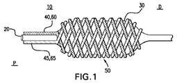
図1および2に示すように、第1の実施例による治療薬搬送器具10は、第1の合成ケーブル40の一部である第1の導体素子60、および拡張可能な部材30に位置される第2の合成ケーブル45の一部である第2の導体素子65を含む。拡張可能な部材30は、例えば人体の血管内への搬送のために、所望の目標部位への搬送用のカテーテル20の先端部に取り付けられる。第1の合成ケーブル40および導体素子60、並びに第2の合成ケーブル45および導体素子65は任意の好適な構造体において拡張可能な部材30に位置される。図1に示すように、所定の実施例において、合成ケーブル40および合成ケーブル45は、編み込み構造体50を形成すべく通常対向する螺旋方向に拡張可能な部材の基端部から先端部まで拡張可能な部材30の最も外側の表面に巻きつけられる。
As shown in FIGS. 1 and 2, the therapeutic
拡張可能な部材30は径方向に拡張することができる任意の好適な器具である。その拡張していない位置(図示しない)において、拡張可能な部材30の直径は、カテーテル20および拡張可能な部材30が組織に外傷を付与することなく、搬送路、例えば脈管系にわたって容易に移動可能となるように形成される。図1に示すように、その拡張した位置において、拡張可能な部材は、合成ケーブル40および45が体腔や組織、あるいは体腔に隣接するか体腔内に位置される血液と接触するように、体腔や血管、即ち血管壁に容易に接近すべく延びる。
The
図1に示す実施例において、拡張可能な部材30はバルーンである。例えば高分子材料のような任意の好適な材料がバルーン30に使用可能である。血管形成術用バルーン材料は、Lee 等による米国特許出願公開第2007/0208365号明細書、およびGoodin等による米国特許出願公開第2007/0208405号明細書を含む多くの特許明細書および特許出願明細書の主題であった。これらの特許文献は、その全体がここで開示されたものとする。バルーン30は、例えば登録商標PEBAX7233、7033や6333のような高いデュロメータの登録商標PEBAX、あるいは登録商標NYLON12から形成される。
In the embodiment shown in FIG. 1, the
バルーン30、即ちバルーン30の層が形成される他の高分子材料の例は、ポリエチレン、登録商標HYTREL、ポリエステル、ポリウレタン、ABS(アクリロニトリル−ブタジエン−スチレンブロック共重合体、ABS/ナイロン混合物、ABS/ポリカーボネート混合物、およびこれらの組み合わせ、スチレン−アクリロニトリル・ブロック共重合体、他のアクリロニトリル共重合体、ポリアクリルアミド、ポリアクリル酸塩、ポリアクリルスルホン・ポリエステル/ポリカプロラクトン混合物、ポリエーテルエーテルケトン(PEEK)、ポリエーテルスルホン(PES)、ポリエーテルイミド(PEI)、ポリエーテルケトン(PEK)、ポリメチルペンテン、ポリフェニレン・エーテル、ポリフェニレン・サルファイド、ポリエチレンおよびポリプロピレンのようなポリオレフィン、エチレン−プロピレン共重合体、エチレン酢酸ビニル共重合体、エチレン−ビニルアルコール共重合体およびポリオレフィンイオノマーのようなオレフィン共重合体、ポリ塩化ビニル、ポリカプロラクタム、N−ビニル−ピロリドン、ポリウレタンおよびポリシロキサンを含む。
Examples of
導体素子60および65は、多くの可能な例の一例に過ぎないが、コバルトベース合金のような任意の好適な導電性材料で構成される。導電性材料は、Thompsonによる米国特許第6592617号明細書を含む多くの特許の主題であった。この特許文献は、その全体がここで開示されたものとする。実施例において、導体素子60および65は316Lステンレス鋼やMP35N合金から形成される。導体素子60および65が形成される他の材料の例は、市場にて入手可能な登録商標Elgiloyおよび登録商標Phynoxである。使用可能な他の金属材料はニチノール・ニッケル・チタンを含む。導体素子60および65は、ポリピロールのような導電性高分子等の導電性材料により覆われる、ポリオレフィン・ファイバのようなワイヤやストランドであってもよい。他の好適な導電性高分子の例はVolk等による米国特許出願公開第2007/0250036号明細書に開示され、その全体がここで開示されたものとする。
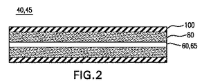
図2に示すように、第1の実施例による治療薬搬送器具10の第1の合成ケーブル40および第2の合成ケーブル45は、さらに電気化学成分80および浸透性の薄膜100を含む。本実施例において、電気化学成分は、各導体素子60および65と、各浸透性の薄膜100との間に位置する。即ち、電気化学成分80は合成ケーブル40および45の内部に位置される。従って、浸透性の薄膜100は、各導体素子60および65の周囲の電気化学成分80を覆う。図1に示すように、治療薬搬送器具が組み立てられると、第1の導体素子60および第2の導体素子65が分離され、電気化学成分80が、第1の導体素子60と第2の導体素子65との間に位置する領域が存在することがわかる。
As shown in FIG. 2, the first
電気化学成分80は治療薬を含む。様々な治療薬が考えられ、これらは発明の趣旨および範囲内にある。治療薬は処置される条件に応じて決定される。例えば、再狭窄の治療については、パクリタクセルが治療薬として使用される。本発明と共に使用可能な多くの好適な治療薬が公知である。例えば、本発明と共に使用可能な治療薬は、O'Conner等による米国特許出願公開第2008/0107794号明細書に開示され、その全体がここに開示されたものとする。
電気化学成分80は電解質を含む。電解質が治療薬の完全性を保持し、本発明による電気化学工程に好適である限り、任意の好適な電解質が使用可能である。いくつかの実施例において、電解質は、例えばリン酸塩、重炭酸ソーダ、カルシウム、塩化物、マグネシウム、カリウムおよび/またはナトリウムのような任意の好適なイオン化された塩である。他の電解質が本発明の範囲内において使用されてもよい。
The
電気化学成分80は有機溶媒により調剤されてもよい。任意の好適な有機溶媒が考えられる。好適に、有機溶媒は生体に対して適合性を備え、無毒である。例えば、所定の実施例において、溶媒は、酢酸エチルとエタノールからなる群から選択される有機溶媒である。本発明と共に使用可能な多くの好適な溶媒が公知である。例えば、本発明と共に使用可能な溶媒は、Freyman による米国特許第7070582号明細書に開示され、その全体がここで開示されたものとする。
浸透性の薄膜100は、治療薬が目標部位130へ薄膜100を横断して通過可能なように好適な任意の材料により構成される。所定の実施例において、浸透性の薄膜100は、例えば登録商標PEBAX2533や3533のような低いデュロメータの登録商標PEBAX、あるいはポリウレタンのような浸透性のポリマから形成される。低いデュロメータの登録商標PEBAXは、Rezac 等による"Effect of Copolymer Composition on the Solubility and Transport of Water and Methanol in a Series of Polyether Amides," Journal of Applied Polymer Science, Vol. 65 (10), pp. 1983 -1993 (1997)に開示されるように、酢酸エチルおよびパクリタクセルに好適な選択透過性を有する。
The
浸透性の薄膜100用の浸透性のポリマは、例えばMgCl2あるいは同様の塩化合物のような塩類の付加によってイオン−伝導性の高分子電解質に転換されてもよい。イオン伝導性高分子は、Morisato等による"Transport properties of PA 12-PTMOZAgBF4 solid polymer electrolyte membranes for olefm/paraffm separation," Desalination, 145, pp. 347-351 (2002年9月10日)、Furtado等による"Electrochemical behavior of polyurethane ether electrolytes/carbon black composites and application to double layer capacitor," Electrochimica Acta, 46, pp. 1629-1634 (2001年3月15日)、およびKujawski等による"Sweeping gas pervaporation with hollow-fiber ion-exchange membranes," Desalination, 162, pp. 129-135 (2004年3月10日)に開示される。
The permeable polymer for the
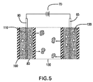
図1乃至5の治療薬搬送器具は、第1の導体素子60および第2の導体素子65が電源に接続されるように、電源を含み、且つ/または電源に接続されるように構成されてもよい。図5は電源70を示す概略図である。電源は、例えば第1の導体素子60および第2の導体素子65を通過するDC電流を生成する低電圧バッテリであってもよい。
The therapeutic drug delivery device of FIGS. 1-5 includes a power source and / or is configured to be connected to a power source such that the
図3に示すように、第1の導体素子60および第2の導体素子65が電源に接続される場合に、第1の導体素子60および第2の導体素子65が異なる極性を有するように電位が印加される。例えば、公知の電気化学回路の構造モデルと一致するように、第1の導体素子60はマイナス極性を有し、第2の導体素子65はプラス極性を有する。この例の目的のために、図3は、陽極としての第1の導体素子60および陰極としての第2の導体素子65を示す。このモデルと一致するように、第1の極性を有する第1の導体素子60は、陰極または陽極のいずれかであり、第2の極性を有する第2の導体素子65は陰極または陽極のいずれかの他方である。図3に示すように、図1に示すような編み込みの実施例において、第1の合成ケーブル40および第2の合成ケーブル45は、編み込み構造体50の螺旋状構造体と一致する軸方向にて長手方向面に沿って交互に位置する。
As shown in FIG. 3, when the
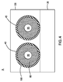
図4は図3の拡大された区域「A」を示す。図4は、隣接する第1の合成ケーブル40および第2の合成ケーブル45を示す横断面図である。図4は、治療薬搬送器具10が位置される目標部位、即ち媒体130をさらに示す。より詳細に後述するように、目標部位における組織および/または流体(例えば血液)は、電気的な回路を完成させる。図4に示すように、拡張可能な部材30が拡張した位置にあるときに、合成ケーブル40および45は媒体130に埋め込まれる。しかしながら、合成ケーブル40および45は、拡張可能な部材30の外側表面が移植される組織に完全に沈められるか埋め込まれる必要はない。例えば、当業者は、ヒトの組織や血液と部分的に接触する度合いを、電気的な回路を完成させるために十分に変更可能であることを認識するであろう。
FIG. 4 shows an enlarged area “A” of FIG. FIG. 4 is a cross-sectional view showing the first
本実施例における目標部位130は、例えば血液、血管の内壁、ヒトの組織、あるいはこれらの任意の組み合わせである。血管は、患者の体内または体外に位置される任意の血管であり、本発明の使用に対して好適である。血管は、心臓の静脈、動脈および室のような血液輸送血管を含む。血管は、当業者に明白な、食道、尿管、腸、脊柱の別体の脊椎骨内に位置される流体のポケットおよび他の任意の好適な血管をさらに含む。本発明によって処置される器官および組織は、体内、体外を問わず任意の哺乳類組織や器官を含む。非制限例は、心臓、肺、脳、肝臓、腎臓、膀胱、腸、胃および膵臓の血管を含む。
The
図5は、治療薬搬送器具が展開し、第1の導体素子60および第2の導体素子65が電源70に接続されるときの、目標部位において組織および/または流体によって完成される電気回路の回路図を示す。図5は、この例の目的のための、陽極としての第1の導体素子60および陰極としての第2の導体素子65を示す。本実施例において、血液および/または組織130は、そこに含まれる自然な塩類により電解質として機能し、これは、公知の電気化学回路における塩橋の役割と同種の陽極および陰極間の回路を完成させる。
FIG. 5 illustrates an electrical circuit that is completed by tissue and / or fluid at a target site when the therapeutic agent delivery device is deployed and the
図5に示すように、治療薬搬送器具が展開し、第1の導体素子60および第2の導体素子65が電源70に接続されるときに、第1の導体素子60および各電気化学成分80の接合面、および第2の導体素子65および各電気化学成分80の接合面にて電気化学反応が生じる。電気化学反応は、陰極にてO2ガス120、陽極にてH2ガス110を生じさせ、これにより第1の合成ケーブル40および第2の合成ケーブル45の浸透性の薄膜100内の圧力を高める。圧力が高められることにより、治療薬は、浸透性の薄膜100を介して目標部位130へ移動される。例えば、低いデュロメータの登録商標PEBAXが浸透性の薄膜100に使用される場合に、パクリタクセルは治療薬用に使用され、酢酸エチルはパクリタクセル用の有機溶媒として使用され、気体の電気化学的な生成により第1の合成ケーブル40および第2の合成ケーブル45内の圧力が高められ、これにより、酢酸エチルによって搬送されるパクリタクセルは浸透性の薄膜100を通過し、目標部位130に溶出される。
As shown in FIG. 5, when the therapeutic agent delivery device is deployed and the
電気化学反応は、例えば酸化還元反応(以下「レドックス反応」と示す)として公知のタイプの人体の適用に好適な任意の反応である。レドックス反応は、電子の移動を含み、当該技術分野において公知である。図1乃至5に示すような所定の実施例において、レドックス反応は水の電気分解である。例えば、熱力学は水の電気分解反応のために1.23Vを必要とし、全体的な反応が化学式Iに示される。
(化I)
(I)2H2O(l)→2H2(g)+O2(g) Eo/V=1.23
陽極および陰極の個別の反応については、化学式II(陰極)および定式III(陽極)において示されるような半反応となる。
(化II)
(II)2H2O+2e−→2OH−+H2 Eo/V=−0.83
(化III)
(III)4OH−→O2+2H2O+4e− Eo/V=+0.4
化学式IIは陰極の半反応を示し、化学式IIIは陽極の半反応を示す。中性の電解質に対する陽極の反応は、陰極にて生成される水酸化物イオンを使用する。この電気分解により、電源70から電圧を印加することにより、水分子の酸化および還元の両者が生じる。これらの反応において、水は還元および分裂され、陰極にてH2ガス110および陽極にてO2ガス120をそれぞれ生成する。これらの半反応により気体が放出され、これにより圧力が高められ、治療薬が浸透性の薄膜100を通過する。図5に示すように、化学式Iによって表わされる反応はH2ガス110を生成する。この反応が生じる導体素子は、陰極である。化学式IIによって表わされる反応は、O2ガス120を生成する。この反応が生じる導体素子は、陽極である。当業者は、上述した反応に対する好適な変更が可能であり、これは本発明の範囲および趣旨内にあることを認識するであろう。
The electrochemical reaction is any reaction suitable for application to a type of human body known as, for example, a redox reaction (hereinafter referred to as “redox reaction”). Redox reactions involve the transfer of electrons and are known in the art. In certain embodiments, such as those shown in FIGS. 1-5, the redox reaction is electrolysis of water. For example, thermodynamics requires 1.23 V for the water electrolysis reaction, and the overall reaction is shown in Formula I.
(Chemical I)
(I) 2H 2 O (l) → 2H 2 (g) + O 2 (g) Eo / V = 1.23
The individual reactions of the anode and cathode are half reactions as shown in Chemical Formula II (cathode) and Formula III (anode).
(Chemical II)
(II) 2H 2 O + 2e − → 2OH − + H 2 Eo / V = −0.83
(Chemical III)
(III) 4OH - → O 2 + 2H 2 O + 4e - Eo / V = + 0.4
Formula II shows the half reaction of the cathode and Formula III shows the half reaction of the anode. The reaction of the anode to the neutral electrolyte uses hydroxide ions generated at the cathode. By this electrolysis, when a voltage is applied from the
図6は第2の実施例を示す。本実施例において、治療薬搬送器具は、拡張可能な部材30に位置される第1の導体素子240および第2の導体素子245を含む。導体素子240および245は、例えば図1乃至5に関して上述したようなポリピロールや他の好適な導電性材料により覆われたポリオレフィン・ファイバである。この例において、第1の導体素子240および第2の導体素子245は、第1の導体素子240および第2の導体素子245を境界とする領域、即ち貯蔵所90を形成する編み込み構造体200を形成すべく相互に交差する。電気化学成分80は、第1の導体素子240および第2の導体素子245を境界とする領域90に位置され、浸透性の薄膜300は、第1の導体素子240と第2の導体素子245とを境界とし且つ電気化学成分80が位置される領域を覆う。本実施例における様々な要素の材料は、図1乃至5の第1の実施例に関して上述したものに類似する。
FIG. 6 shows a second embodiment. In this example, the therapeutic agent delivery device includes a
図1乃至5の第1の実施例の手術を、治療薬搬送器具10を使用する方法に関して後述する。説明の目的のみのために、本実施例は冠状動脈の再狭窄に関して後述する。当業者は、治療薬搬送器具10が他の好適な応用において使用可能であることを容易に認識するであろう。
The operation of the first embodiment of FIGS. 1-5 will be described below with respect to a method of using the therapeutic
実地において、例えば、医師は、カテーテル20の先端部(これは拡張可能な部材30における治療薬搬送領域を備えた部分である)を、例えば患者の大腿動脈を通して挿入し、血管を通して治療薬搬送器具10を冠状動脈における目標部位130へ案内する。治療薬搬送領域が目標部位に位置されると、編み込み構造体50の第1の導体素子60および第2の導体素子65は、電源70に接続される。電源70は第1の導体素子60および第2の導体素子65に電位を印加する。従って、上述したように、導体素子60および65は陽極または陰極として機能する。電気化学成分80および各導体素子60、65を含む薄膜100によって包囲される空間は、電気化学セルとして機能する。電気化学成分80、例えばパクリタクセル酢酸エチル−水リン酸塩調合剤は、例えばTimbola 等による"Electrochemical Oxidation of Quercetin in Hydro-Alcoholic Solution," J. Braz. Chem. Soc, 17(1), pp. 139-148(2006年1月/2月)に開示されるような含水量を有する非水電解質として機能する。目標部位130における血液または組織は、電解質として機能することにより電気回路を完成させる。
In practice, for example, a physician inserts the distal end of the catheter 20 (which is the portion of the
特に、電源70が第1の導体素子60および第2の導体素子65に適用される場合に、電気化学反応は気体を放出する。気体の放出により、第1の合成ケーブル40および第2の合成ケーブル45内の圧力が高められ、これにより、第1の合成ケーブル40および第2の合成ケーブル45の治療薬は、各浸透性の薄膜100を通過し、目標部位130へ溶出する。電気化学のレドックス反応により圧力が高められることに付加的に、電気化学成分80の薄膜100を通過する運動は、薄膜100自体の電解質の性質によってさらに促進されてもよい。
In particular, when the
発明の所定の実施例に従って、血管形成術処置中に、医師は、要求に応じて電源70から来る電気をオン・オフすることができる。合成ケーブル40および45内に生じる圧力勾配により、浸透性の薄膜100を横断するパクリタクセル酢酸エチル調合剤の迅速な「オン・デマンド」の制御された輸送が可能となる。
In accordance with certain embodiments of the invention, during an angioplasty procedure, the physician can turn on and off electricity coming from the
図6の第2の実施例の手術は第1の実施例の手術に類似する。電源70は導体素子240および245に電位を印加し、これにより貯蔵所90内の圧力を高める電気化学反応を生じさせる。圧力により、治療薬は、浸透性の薄膜300を通過し、目標位置130に至る。
The operation of the second embodiment of FIG. 6 is similar to the operation of the first embodiment. The
図1乃至6に示す実施例において、ここに開示される器具および方法の電気化学回路により、治療薬は、病変部位へ制御されて迅速に搬送される。この点において、これらの実施例は、侵襲性を最小限に抑えた挿入処置を開示し、ここで拡張可能な部材30は、目標部位への経路における組織の崩壊および組織への損傷を回避すべく非拡張位置に配置される。目標部位に配置されると、拡張可能な部材30は拡張する。この時点まで、治療薬は浸透性の薄膜100内に保持される。公知の方法および器具と異なり、医師が要求される位置に治療薬搬送器具10を位置決めするまで、治療薬は、血流や組織中の、消失するか治療薬と反応する外的粒子から保護された状態を保持する。この時点において、医師は、電気化学反応を生じさせる電源70を操作することにより、電気化学成分80を介した目標部位130への治療薬の投与量および投与速度を制御することができる。目標部位130の組織が電気化学回路の一部であることを理由の1つとして、部位に対する治療薬の投与が改善され、治療薬の損失は最小限とされ、これにより、公知の器具および方法に対する器具の全体的な費用が大きく低減され、且つ性能が改善される。
In the embodiment shown in FIGS. 1-6, the electrochemical circuit of the instrument and method disclosed herein allows therapeutic agent to be controlled and rapidly delivered to the lesion site. In this regard, these embodiments disclose a minimally invasive insertion procedure wherein the
開示された実施例は、いくつかの典型的な例に関して上述された。開示された実施例の多くの変形が当業者に明白であろう。これらの変形は、請求の範囲によってのみ制限される本発明の教示の範囲内にあるものといえる。 The disclosed embodiments have been described above with reference to some typical examples. Many variations of the disclosed embodiments will be apparent to those skilled in the art. These variations are considered to be within the scope of the present teachings, which is limited only by the scope of the claims.
Claims (20)
第2の導体素子と、
該第1の導体素子と第2の導体素子との間に位置する電解質および治療薬を含む電気化学成分と、
同電気化学成分を覆う浸透性の薄膜とを備え、
該第1の導体素子および第2の導体素子は電源に接続されることと、
該第1の導体素子および第2の導体素子が電源に接続される場合に、電気化学反応が生じ、これにより治療薬は浸透性の薄膜を通過し、目標部位へ溶出されることとを特徴とする治療薬搬送器具。 A first conductor element;
A second conductor element;
An electrochemical component comprising an electrolyte and a therapeutic agent located between the first conductor element and the second conductor element;
A permeable thin film covering the same electrochemical component,
The first conductor element and the second conductor element are connected to a power source;
When the first conductor element and the second conductor element are connected to a power source, an electrochemical reaction occurs, whereby the therapeutic agent passes through the permeable thin film and is eluted to the target site. A therapeutic drug delivery device.
該第1の合成ケーブルは第1の導体素子、電気化学成分、および浸透性の薄膜を含み、同浸透性の薄膜は、第1の導体素子を包囲し、電気化学成分は第1の導体素子と浸透性の薄膜との間に位置されることと、
第1の導体素子および第2の導体素子が電源に接続される場合に、電気化学反応が生じ、これにより第1合成ケーブルの治療薬は、第1の合成ケーブルの浸透性の薄膜を通過し、目標部位へ溶出することとを特徴とする請求項1に記載の治療薬搬送器具。 The first conductor element is part of a first composite cable;
The first composite cable includes a first conductor element, an electrochemical component, and a permeable thin film, the permeable thin film surrounding the first conductor element, the electrochemical component being a first conductive element. Between the permeable membrane and the permeable membrane,
An electrochemical reaction occurs when the first conductor element and the second conductor element are connected to the power source, whereby the therapeutic agent of the first synthetic cable passes through the permeable thin film of the first synthetic cable. The therapeutic drug delivery device according to claim 1, wherein the therapeutic drug delivery device is eluted to a target site.
該第2の合成ケーブルは第2の導体素子、電解質と治療薬とを含む第2の電気化学成分、および第2の浸透性の薄膜を含み、同第2の浸透性の薄膜は、第2の導体素子を包囲し、第2の電気化学成分は第2の導体素子と第2の浸透性の薄膜との間に位置されることと、
第1の導体素子および第2の導体素子が電源に接続される場合に、電気化学反応が生じ、これにより第2の合成ケーブルの治療薬は、第2の合成ケーブルの第2の浸透性の薄膜を通過し、目標部位へ溶出することとを特徴とする請求項2に記載の治療薬搬送器具。 The second conductor element is part of a second composite cable;
The second synthetic cable includes a second conductor element, a second electrochemical component including an electrolyte and a therapeutic agent, and a second permeable thin film, wherein the second permeable thin film is a second permeable thin film. The second electrochemical component is located between the second conductive element and the second permeable thin film;
When the first conductor element and the second conductor element are connected to a power source, an electrochemical reaction occurs, whereby the second synthetic cable therapeutic agent has a second permeable property of the second synthetic cable. The therapeutic drug delivery device according to claim 2, wherein the therapeutic drug delivery device passes through the thin film and elutes to a target site.
同カテーテルの端部に取り付けられる拡張可能な部材とをさらに備え、
該第1の導体素子および第2の導体素子は拡張可能な部材に位置されることを特徴とする請求項1に記載の治療薬搬送器具。 A catheter;
And an expandable member attached to the end of the catheter,
The therapeutic drug delivery device according to claim 1, wherein the first conductor element and the second conductor element are located on an expandable member.
電気化学成分は、第1の導体素子および第2の導体素子を境界とする領域に位置されることと、
浸透性の薄膜は、第1の導体素子および第2の導体素子を境界とし且つ電気化学成分が位置する領域を覆うこととを特徴とする請求項1に記載の治療薬搬送器具。 The first conductor element and the second conductor element are positioned on the expandable member and intersect each other to form a region bounded by the first conductor element and the second conductor element;
The electrochemical component is located in a region bounded by the first conductor element and the second conductor element;
2. The therapeutic drug delivery device according to claim 1, wherein the permeable thin film covers the region where the electrochemical component is located with the first conductor element and the second conductor element as a boundary.
(a)治療薬搬送器具を提供する工程と、同治療薬搬送器具は、
(i)電源に接続される第1の導体素子と、
(ii)電源に接続される第2の導体素子と、
(iii)器具の治療薬搬送領域にて第1の導体素子と第2の導体素子との間に位置される電気化学成分と、同電気化学成分は、電解質および治療薬を含み、
(iv)電気化学成分を覆う浸透性の薄膜とを含み、
(b)器具の治療薬搬送領域を目標部位に位置決めする工程と、
(c)第1の導体素子および第2の導体素子を電源に接続して電気化学反応を生じさせ、これにより治療薬に浸透性の薄膜を通過させ、目標部位へ溶出させる接続工程とを含むことを特徴とする目標部位に治療薬を搬送する方法。 A method of delivering a therapeutic agent to a target site,
(A) providing a therapeutic drug delivery device, and the therapeutic drug delivery device,
(I) a first conductor element connected to a power source;
(Ii) a second conductor element connected to the power source;
(Iii) an electrochemical component positioned between the first conductor element and the second conductor element in the therapeutic agent delivery region of the device, the electrochemical component comprising an electrolyte and a therapeutic agent;
(Iv) a permeable thin film covering the electrochemical component;
(B) positioning the therapeutic drug delivery region of the instrument at the target site;
(C) connecting the first conductor element and the second conductor element to a power source to cause an electrochemical reaction, thereby allowing the therapeutic agent to pass through the permeable thin film and eluting to the target site. A method of delivering a therapeutic agent to a target site characterized by:
Applications Claiming Priority (3)
| Application Number | Priority Date | Filing Date | Title |
|---|---|---|---|
| US18574509P | 2009-06-10 | 2009-06-10 | |
| US61/185,745 | 2009-06-10 | ||
| PCT/US2010/036403 WO2010144266A2 (en) | 2009-06-10 | 2010-05-27 | Electrochemical therapeutic agent delivery device |
Publications (2)
| Publication Number | Publication Date |
|---|---|
| JP2012529348A true JP2012529348A (en) | 2012-11-22 |
| JP2012529348A5 JP2012529348A5 (en) | 2013-07-11 |
Family
ID=42561425
Family Applications (1)
| Application Number | Title | Priority Date | Filing Date |
|---|---|---|---|
| JP2012514987A Pending JP2012529348A (en) | 2009-06-10 | 2010-05-27 | Electrochemical therapeutic device |
Country Status (4)
| Country | Link |
|---|---|
| US (1) | US8591494B2 (en) |
| EP (1) | EP2440262A2 (en) |
| JP (1) | JP2012529348A (en) |
| WO (1) | WO2010144266A2 (en) |
Families Citing this family (17)
| Publication number | Priority date | Publication date | Assignee | Title |
|---|---|---|---|---|
| US20040226556A1 (en) | 2003-05-13 | 2004-11-18 | Deem Mark E. | Apparatus for treating asthma using neurotoxin |
| US8153181B2 (en) | 2006-11-14 | 2012-04-10 | Boston Scientific Scimed, Inc. | Medical devices and related methods |
| ES2409759T3 (en) | 2007-01-21 | 2013-06-27 | Hemoteq Ag | Medical product for the treatment of stenosis of the channels of the body and for the prevention of threatening stenosis |
| US9192697B2 (en) | 2007-07-03 | 2015-11-24 | Hemoteq Ag | Balloon catheter for treating stenosis of body passages and for preventing threatening restenosis |
| US8483831B1 (en) | 2008-02-15 | 2013-07-09 | Holaira, Inc. | System and method for bronchial dilation |
| WO2009137819A1 (en) | 2008-05-09 | 2009-11-12 | Innovative Pulmonary Solutions, Inc. | Systems, assemblies, and methods for treating a bronchial tree |
| EP2451496B1 (en) | 2009-07-10 | 2015-07-22 | Boston Scientific Scimed, Inc. | Use of nanocrystals for a drug delivery balloon |
| EP2962707B1 (en) | 2009-07-17 | 2019-07-24 | Boston Scientific Scimed, Inc. | Drug delivery balloons with improved crystal size and density |
| WO2011056684A2 (en) | 2009-10-27 | 2011-05-12 | Innovative Pulmonary Solutions, Inc. | Delivery devices with coolable energy emitting assemblies |
| US8911439B2 (en) | 2009-11-11 | 2014-12-16 | Holaira, Inc. | Non-invasive and minimally invasive denervation methods and systems for performing the same |
| KR101820542B1 (en) | 2009-11-11 | 2018-01-19 | 호라이라 인코포레이티드 | Systems, apparatuses, and methods for treating tissue and controlling stenosis |
| EP2525860B1 (en) * | 2010-01-21 | 2015-04-08 | Boston Scientific Scimed, Inc. | Balloon catheters with therapeutic agent in balloon folds and methods of making the same |
| US9227041B2 (en) | 2010-04-09 | 2016-01-05 | Boston Scientific Scimed, Inc. | Balloon catheters with fibers for delivery of therapeutic agent and methods of making the same |
| EP2611476B1 (en) | 2010-09-02 | 2016-08-10 | Boston Scientific Scimed, Inc. | Coating process for drug delivery balloons using heat-induced rewrap memory |
| US8669360B2 (en) | 2011-08-05 | 2014-03-11 | Boston Scientific Scimed, Inc. | Methods of converting amorphous drug substance into crystalline form |
| US9056152B2 (en) | 2011-08-25 | 2015-06-16 | Boston Scientific Scimed, Inc. | Medical device with crystalline drug coating |
| US9398933B2 (en) | 2012-12-27 | 2016-07-26 | Holaira, Inc. | Methods for improving drug efficacy including a combination of drug administration and nerve modulation |
Citations (2)
| Publication number | Priority date | Publication date | Assignee | Title |
|---|---|---|---|---|
| JP2000051367A (en) * | 1998-06-30 | 2000-02-22 | Ethicon Inc | Stent coating method |
| WO2007111365A1 (en) * | 2006-03-29 | 2007-10-04 | Tti Ellebeau, Inc. | Catheter type iontophoresis apparatus |
Family Cites Families (17)
| Publication number | Priority date | Publication date | Assignee | Title |
|---|---|---|---|---|
| US4073287A (en) * | 1976-04-05 | 1978-02-14 | American Medical Systems, Inc. | Urethral profilometry catheter |
| US5843089A (en) | 1990-12-28 | 1998-12-01 | Boston Scientific Corporation | Stent lining |
| ATE123658T1 (en) * | 1990-06-15 | 1995-06-15 | Cortrak Medical Inc | DEVICE FOR DISPENSING MEDICATIONS. |
| WO1993007920A1 (en) | 1991-10-24 | 1993-04-29 | Insutech, Incorporated | Gas pressure driven infusion system by hydrogel electrolysis |
| US5824048A (en) | 1993-04-26 | 1998-10-20 | Medtronic, Inc. | Method for delivering a therapeutic substance to a body lumen |
| US6592617B2 (en) | 1996-04-30 | 2003-07-15 | Boston Scientific Scimed, Inc. | Three-dimensional braided covered stent |
| FR2755372B1 (en) | 1996-11-07 | 1998-12-24 | Elf Aquitaine | IONOPHORESIS DEVICE COMPRISING AT LEAST ONE MEMBRANE ELECTRODE ASSEMBLY FOR THE TRANSCUTANEOUS ADMINISTRATION OF ACTIVE PRINCIPLES TO A SUBJECT |
| US6123718A (en) | 1998-11-02 | 2000-09-26 | Polymerex Medical Corp. | Balloon catheter |
| AU2623201A (en) | 1999-12-30 | 2001-07-16 | Kam W Leong | Controlled delivery of therapeutic agents by insertable medical devices |
| US6625486B2 (en) | 2001-04-11 | 2003-09-23 | Advanced Cardiovascular Systems, Inc. | Method and apparatus for intracellular delivery of an agent |
| US6537195B2 (en) * | 2001-05-07 | 2003-03-25 | Xoft, Microtube, Inc. | Combination x-ray radiation and drug delivery devices and methods for inhibiting hyperplasia |
| US7070582B2 (en) | 2002-08-09 | 2006-07-04 | Boston Scientific Scimed, Inc. | Injection devices that provide reduced outflow of therapeutic agents and methods of delivering therapeutic agents |
| US7850645B2 (en) * | 2005-02-11 | 2010-12-14 | Boston Scientific Scimed, Inc. | Internal medical devices for delivery of therapeutic agent in conjunction with a source of electrical power |
| US8043673B2 (en) | 2006-03-02 | 2011-10-25 | Boston Scientific Scimed, Inc. | Method to make tube-in-tube balloon |
| US20070208405A1 (en) | 2006-03-06 | 2007-09-06 | Boston Scientific Scimed, Inc. | Stent delivery catheter |
| US7766896B2 (en) | 2006-04-25 | 2010-08-03 | Boston Scientific Scimed, Inc. | Variable stiffness catheter assembly |
| US8043651B2 (en) | 2006-11-02 | 2011-10-25 | Boston Scientific Scimed, Inc. | System and method for coating a medical device |
-
2010
- 2010-05-27 WO PCT/US2010/036403 patent/WO2010144266A2/en active Application Filing
- 2010-05-27 EP EP10721086A patent/EP2440262A2/en not_active Withdrawn
- 2010-05-27 US US12/789,069 patent/US8591494B2/en not_active Expired - Fee Related
- 2010-05-27 JP JP2012514987A patent/JP2012529348A/en active Pending
Patent Citations (2)
| Publication number | Priority date | Publication date | Assignee | Title |
|---|---|---|---|---|
| JP2000051367A (en) * | 1998-06-30 | 2000-02-22 | Ethicon Inc | Stent coating method |
| WO2007111365A1 (en) * | 2006-03-29 | 2007-10-04 | Tti Ellebeau, Inc. | Catheter type iontophoresis apparatus |
Also Published As
| Publication number | Publication date |
|---|---|
| EP2440262A2 (en) | 2012-04-18 |
| WO2010144266A2 (en) | 2010-12-16 |
| US8591494B2 (en) | 2013-11-26 |
| WO2010144266A3 (en) | 2011-03-17 |
| US20100318020A1 (en) | 2010-12-16 |
Similar Documents
| Publication | Publication Date | Title |
|---|---|---|
| JP2012529348A (en) | Electrochemical therapeutic device | |
| US7292885B2 (en) | Mechanical apparatus and method for dilating and delivering a therapeutic agent to a site of treatment | |
| US7519418B2 (en) | Mechanical apparatus and method for dilating and delivering a therapeutic agent to a site of treatment | |
| JP3372250B2 (en) | Internal tissue drug penetration device | |
| US5505700A (en) | Electro-osmotic infusion catheter | |
| US5807306A (en) | Polymer matrix drug delivery apparatus | |
| CA2547605A1 (en) | Polymer coated device for electrically mediated drug delivery | |
| WO2014163987A1 (en) | Medical devices for modulating nerves | |
| JP2000509623A (en) | Combination of coronary stent placement and partial drug administration | |
| JP2020531139A (en) | Calcium electroporation delivery device | |
| US11752312B2 (en) | Drug device electroporation angioplasty system | |
| US20040034336A1 (en) | Charged liposomes/micelles with encapsulted medical compounds | |
| AU2009219365A1 (en) | Delivery apparatus and associated method | |
| EP1620162A1 (en) | Mechanical apparatus and method for dilating and delivering a therapeutic agent | |
| WO2007111365A1 (en) | Catheter type iontophoresis apparatus | |
| WO2005048988A1 (en) | Charged liposomes/micelles with encapsulated medical compounds |
Legal Events
| Date | Code | Title | Description |
|---|---|---|---|
| A521 | Request for written amendment filed |
Free format text: JAPANESE INTERMEDIATE CODE: A523 Effective date: 20130524 |
|
| A621 | Written request for application examination |
Free format text: JAPANESE INTERMEDIATE CODE: A621 Effective date: 20130524 |
|
| A977 | Report on retrieval |
Free format text: JAPANESE INTERMEDIATE CODE: A971007 Effective date: 20140227 |
|
| A131 | Notification of reasons for refusal |
Free format text: JAPANESE INTERMEDIATE CODE: A131 Effective date: 20140304 |
|
| A02 | Decision of refusal |
Free format text: JAPANESE INTERMEDIATE CODE: A02 Effective date: 20140902 |