JP2012526018A - Cutting device - Google Patents
Cutting device Download PDFInfo
- Publication number
- JP2012526018A JP2012526018A JP2012508857A JP2012508857A JP2012526018A JP 2012526018 A JP2012526018 A JP 2012526018A JP 2012508857 A JP2012508857 A JP 2012508857A JP 2012508857 A JP2012508857 A JP 2012508857A JP 2012526018 A JP2012526018 A JP 2012526018A
- Authority
- JP
- Japan
- Prior art keywords
- film
- pallet
- wrap
- height
- article
- Prior art date
- Legal status (The legal status is an assumption and is not a legal conclusion. Google has not performed a legal analysis and makes no representation as to the accuracy of the status listed.)
- Pending
Links
- 238000005520 cutting process Methods 0.000 title claims abstract description 79
- 239000004033 plastic Substances 0.000 claims abstract description 6
- 230000032258 transport Effects 0.000 claims abstract description 5
- 238000004519 manufacturing process Methods 0.000 claims description 21
- 238000000034 method Methods 0.000 claims description 18
- 230000008569 process Effects 0.000 claims description 13
- 230000009471 action Effects 0.000 claims description 11
- 230000033001 locomotion Effects 0.000 claims description 9
- 238000003860 storage Methods 0.000 claims description 9
- 238000013459 approach Methods 0.000 claims description 4
- 230000000694 effects Effects 0.000 claims description 4
- 230000003466 anti-cipated effect Effects 0.000 claims description 2
- 239000000872 buffer Substances 0.000 claims description 2
- 239000000463 material Substances 0.000 claims description 2
- 230000007246 mechanism Effects 0.000 claims description 2
- 238000011084 recovery Methods 0.000 claims description 2
- 230000005540 biological transmission Effects 0.000 claims 1
- 239000002537 cosmetic Substances 0.000 claims 1
- 230000005484 gravity Effects 0.000 claims 1
- 230000003647 oxidation Effects 0.000 claims 1
- 238000007254 oxidation reaction Methods 0.000 claims 1
- 230000009467 reduction Effects 0.000 claims 1
- 238000004260 weight control Methods 0.000 claims 1
- 230000000717 retained effect Effects 0.000 abstract 1
- 239000010408 film Substances 0.000 description 100
- 208000027418 Wounds and injury Diseases 0.000 description 12
- 229920006302 stretch film Polymers 0.000 description 6
- 229910000831 Steel Inorganic materials 0.000 description 3
- 239000002184 metal Substances 0.000 description 3
- 239000002985 plastic film Substances 0.000 description 3
- 229920006255 plastic film Polymers 0.000 description 3
- 238000005096 rolling process Methods 0.000 description 3
- 238000003892 spreading Methods 0.000 description 3
- 230000007480 spreading Effects 0.000 description 3
- 239000010959 steel Substances 0.000 description 3
- 238000004804 winding Methods 0.000 description 3
- 238000005452 bending Methods 0.000 description 2
- 230000006378 damage Effects 0.000 description 2
- 210000000707 wrist Anatomy 0.000 description 2
- 208000019901 Anxiety disease Diseases 0.000 description 1
- 208000008035 Back Pain Diseases 0.000 description 1
- 208000025940 Back injury Diseases 0.000 description 1
- 229910001335 Galvanized steel Inorganic materials 0.000 description 1
- 210000003423 ankle Anatomy 0.000 description 1
- 230000036506 anxiety Effects 0.000 description 1
- 230000000712 assembly Effects 0.000 description 1
- 238000000429 assembly Methods 0.000 description 1
- 230000004888 barrier function Effects 0.000 description 1
- 239000010953 base metal Substances 0.000 description 1
- 239000006227 byproduct Substances 0.000 description 1
- 230000008859 change Effects 0.000 description 1
- 230000001934 delay Effects 0.000 description 1
- 239000008397 galvanized steel Substances 0.000 description 1
- 230000000977 initiatory effect Effects 0.000 description 1
- 208000014674 injury Diseases 0.000 description 1
- 230000001788 irregular Effects 0.000 description 1
- 238000005461 lubrication Methods 0.000 description 1
- 210000004705 lumbosacral region Anatomy 0.000 description 1
- NJPPVKZQTLUDBO-UHFFFAOYSA-N novaluron Chemical compound C1=C(Cl)C(OC(F)(F)C(OC(F)(F)F)F)=CC=C1NC(=O)NC(=O)C1=C(F)C=CC=C1F NJPPVKZQTLUDBO-UHFFFAOYSA-N 0.000 description 1
- 239000012785 packaging film Substances 0.000 description 1
- 229920006280 packaging film Polymers 0.000 description 1
- 238000004806 packaging method and process Methods 0.000 description 1
- 239000000047 product Substances 0.000 description 1
- 238000010408 sweeping Methods 0.000 description 1
- 239000010409 thin film Substances 0.000 description 1
- 239000002023 wood Substances 0.000 description 1
Images


Classifications
-
- B—PERFORMING OPERATIONS; TRANSPORTING
- B65—CONVEYING; PACKING; STORING; HANDLING THIN OR FILAMENTARY MATERIAL
- B65B—MACHINES, APPARATUS OR DEVICES FOR, OR METHODS OF, PACKAGING ARTICLES OR MATERIALS; UNPACKING
- B65B67/00—Apparatus or devices facilitating manual packaging operations; Sack holders
- B65B67/08—Wrapping of articles
-
- B—PERFORMING OPERATIONS; TRANSPORTING
- B65—CONVEYING; PACKING; STORING; HANDLING THIN OR FILAMENTARY MATERIAL
- B65B—MACHINES, APPARATUS OR DEVICES FOR, OR METHODS OF, PACKAGING ARTICLES OR MATERIALS; UNPACKING
- B65B11/00—Wrapping, e.g. partially or wholly enclosing, articles or quantities of material, in strips, sheets or blanks, of flexible material
- B65B11/02—Wrapping articles or quantities of material, without changing their position during the wrapping operation, e.g. in moulds with hinged folders
- B65B11/025—Wrapping articles or quantities of material, without changing their position during the wrapping operation, e.g. in moulds with hinged folders by webs revolving around stationary articles
Landscapes
- Engineering & Computer Science (AREA)
- Mechanical Engineering (AREA)
- Basic Packing Technique (AREA)
- Packages (AREA)
Abstract
重ねられたゆるい物品(17)のパレットをラッピングするための好適なロール(2)からプラスチックストレッチラップフィルム(12)を切り出すためのトロリー装置は、支持や可動性を提供する車輪又はキャスタを有する輸送可能なフレーム構造(8)により特徴づけられており、フレームはロール(6)の高さを調節する手段を有し、フレームはストレッチラップフィルムに張りを生じさせるための支点として用いられるために配置されるガイドローラ(7)及び操作の完了時、ストレッチラップフィルムを取り去るためのカッタ(2)を提供し、ストレッチラップフィルムの端部は次の使用のために保持される。
【選択図】図1
A trolley device for cutting a plastic stretch wrap film (12) from a suitable roll (2) for wrapping a pallet of stacked loose articles (17) transports with wheels or casters providing support and mobility Characterized by a possible frame structure (8), the frame has means to adjust the height of the roll (6), the frame is arranged to be used as a fulcrum for creating tension in the stretch wrap film Guide roller (7) to be provided and a cutter (2) for removal of the stretch wrap film upon completion of the operation, the end of the stretch wrap film being retained for subsequent use.
[Selection] Figure 1
Description
装置は一般的な移送パレットの底部又は上部に配置される物品を囲み、かつ結束するプラスチックストレッチフィルムを切り出して引っ張るための手段として開示される。 The apparatus is disclosed as a means for cutting and pulling a plastic stretch film that surrounds and binds articles placed at the bottom or top of a typical transfer pallet.
一般的な移送パレットは、パレットジャッキ又はフォークリフトにより吊り上げられ、かつ保管用の棚又は移送用のトラックベット上に持ち上げられる前に上面に置かれる物品用にプラスチック又は木で作ることができる。パレットはフォークリフトの歯が入る開口を有し、また、パレットに固定され、本開示に言及されるストレッチフィルム用の空間を提供する。 Typical transfer pallets can be made of plastic or wood for articles that are lifted by pallet jacks or forklifts and placed on the top surface before being lifted onto storage shelves or transfer truck beds. The pallet has an opening for receiving the forklift teeth and is secured to the pallet to provide space for the stretch film referred to in this disclosure.
これは典型的なパレットであり、このことからこの方式のパレットがすべての基準となる。 This is a typical pallet, so this type of pallet is the basis for all.
世界中の多くの工場で製造される物品は、保管中又は輸送中、封じ込め又は保護を必要とし、これは物品の周りに伸ばされ、かつ結束されるプラスチックフィルムにより効果的に実施される。手動、かつ機械的にアシストされた手段により、物品を覆うためにプラスチックフィルムを切り出したり、引っ張ったりすることが可能となる。 Articles manufactured in many factories around the world require containment or protection during storage or transport, which is effectively performed by a plastic film that is stretched and bound around the article. Manual and mechanically assisted means allow the plastic film to be cut or pulled to cover the article.
保管中又は輸送中、こぼれないようにするべく一かたまりを形成するために共に拘束される、一般にカートン、束又は袋状に重ねられる物品は、輸送又は保管において、さらに物品を保護するために耐紫外線の最も一般的な又は着色された、又は黒色の包装フィルムであり、天候、窃盗又は視界から保護されうる。 Articles that are generally constrained together to form a mass to prevent spillage during storage or transportation, generally stacked in cartons, bundles, or bags, are resistant to further protection during transportation or storage. The most common or colored or black packaging film of ultraviolet light and can be protected from weather, theft or visibility.
フィルムを物品の周りに巻くためのいくつかの方法がある。 There are several ways to wrap a film around an article.
ラップフィルムを手動で巻くために一方法は以下のように記載される。 One method for manually winding a wrap film is described as follows.
フィルムの端部をパレットに固定することにより、又は巻かれる物品の下に端部を挟むことにより、まず取り付けるフィルムのロールから十分なフィルムを引っ張り出した後、指を厚紙の芯の各開口端部内に挿入し、供給フィルムの正面ロールからの引き出しを可能とし、後方へ歩行を進めるにつれて、ロールを縦に垂直に、物品周りを水平に運ぶことにより巻かれる。 First pull out enough film from the roll of film to be attached by fixing the end of the film to the pallet, or by pinching the end under the article to be wound, then place your fingers on each open end of the cardboard core It is inserted into the section, allowing the supply film to be pulled out from the front roll, and as it walks backward, it is wound by carrying the roll vertically and vertically around the article.
このラッピング工程を開始するために、フィルムをパレット上に固定した後、物品の下部と物品を輸送するために置くパレットの上端部とに重ねるので、フィルムの下端を地上レベルまで下げなければならない。 To begin this lapping process, after the film is fixed on the pallet, it overlaps with the lower part of the article and the upper end of the pallet where the article is placed for transport, so the lower end of the film must be lowered to the ground level.
フィルムは物品を締まった一個体に密着させるように伸ばされ、これはパレット及び物品の各隅部周りにフィルムを伸ばすために曲がりつつ、さらに後方に歩行しながら手でフィルムロール及び芯を絞ることにより、手動でフィルムを停止させたり、ロールからの引き出しを制限したりする必要がある。 The film is stretched to bring the article into close contact with the individual, which bends to stretch the film around each corner of the pallet and article, and then squeezes the film roll and core by hand while walking backwards. Therefore, it is necessary to manually stop the film or restrict the drawing from the roll.
一旦フィルムがパレットの各隅部で物品と接触すると、次の隅部に向かって進みながらフィルムロール芯の手の握りを放すことにより、フィルムをロールから引き出すことが可能となる。 Once the film is in contact with the article at each corner of the pallet, the film can be pulled from the roll by releasing the hand of the film roll core as it proceeds toward the next corner.
パレット及び物品をラップ用フィルムで囲みながらの後方への歩行は、フィルムが物品の底部から、ラップ用フィルムを引き出されるロールから切り離すために、切り取ったり、ナイフで切ったり、あるいはとがらせた手で穴を開けたりする、上部まで覆うまでラッピング高さを徐々に高くし続ける。 Walking backwards while wrapping the pallet and article with wrapping film can be done with a hand that has been cut, knifed or pointed to separate the film from the bottom of the article from the roll from which the wrapping film is drawn. Keep the wrapping height gradually higher until you make holes or cover up to the top.
手動でのラッピング作業の一般的なリスクは、重いラップ用フィルムのロールを運ぶこと、地面でラッピング始め、進めるために、長時間かがんでいること、フィルムを伸ばすために胴をねじることによるぎっくり腰、迅速なロール芯の巻き戻しを扱うことで生じる摩擦からの指や手の火傷、可能な頭上高さまで巻くことで生じる天井持ち上げによる筋違い、完成した包装物がなく、フィルムをロールから切り取るため補助がない状態で裁断作業が必要とされた場合、フィルムを巻端部、又はナイフカットで切り離すために、より強固に結束したラップ用フィルムを引き裂こうとすることによる手首のねんざなどが組み合わさった腰椎ねんざである。 The common risks of manual wrapping are: carrying heavy rolls of wrapping film, starting wrapping on the ground, crouching for a long time to advance, twisting the torso to stretch the film Assists to cut the film off the roll, without finger or hand burns from friction caused by handling quick roll core unwinding, streaks due to ceiling lifting caused by rolling to a possible overhead height, no finished packaging When cutting work is required in the absence of wrapping, it is necessary to combine the use of a wrist strap by trying to tear the film for wrapping that has been tightly bound in order to separate the film with a roll edge or knife cut. A lumbar spine.
ストレッチフィルムを用いて物品を手動でラッピングするのに用いるものは、ハンドル形態であり、その上にはラップロール厚紙芯が置かれており、スラスト軸受、圧力バネ又はテーパ末端プラグ、ベースプレート又はフレームの配置を含んでもよく、厚紙芯を通る長いネジ棒が組付けられており、組み合わせるとやや重くなるが、より容易にアセンブリを運ぶ2つのハンドルグリップも提供する。 What is used to manually wrap an article with a stretch film is in the form of a handle, on which a wrap roll cardboard core is placed, which is a thrust bearing, pressure spring or tapered end plug, base plate or frame Arrangements may be included and a long screw rod passing through the cardboard core is assembled to provide two handle grips that are slightly heavier when combined but carry the assembly more easily.
上述のハンドル配置の欠点は失われやすい部品が多いことであり、いくつかは保持するのに潤滑が必要であり、装置で巻かれるすべての物品は、握りによる利便性にもかかわらず、地上から頭上の高さまで運ぶ必要がある全アセンブリの重さだけでなく摩擦が定抵抗であるとき、ラッピング作業を開始するために、かかる転がり摩擦、ロールからフィルムの引き出しを試みる不安を受けて、かかる同じ張力が必要となることが想定される。 The disadvantage of the handle arrangement described above is that many parts are easily lost, some require lubrication to hold, and all items that are wound on the device are off the ground, despite the convenience of gripping. When the friction is constant resistance as well as the weight of the whole assembly that needs to be carried to overhead, it takes such rolling friction to receive the anxiety to try to pull the film out of the roll, in order to start the wrapping operation. It is assumed that tension is required.
地上レベルまで腰を曲げたり、装置を運んだりすることによる背中の痛みは、一人でロールを運ぶのに経験したのと同じかそれ以上であり、ラッピング工程の終わりでフィルムを切断する任意の手段も、薄い、粘着性の性質のため、見つけたり、ロールから均一にはがすことがとても困難であるフィルムの切断端部がロールに貼り戻らないようにする任意の手段も未だにない。 Back pain from bending the waist or carrying the device to the ground level is equal to or greater than that experienced in carrying the roll alone, and any means of cutting the film at the end of the lapping process However, there is still no optional means to prevent the cut edge of the film from sticking back to the roll, which is very difficult to find or peel evenly from the roll because of its thin, tacky nature.
物品をストレッチフィルムで巻く別の手段は自動機械であり、一般にターンテーブルを動かす電動手段を要するターンテーブルと、減速してフィルムを送り出すために電動であることもある切り出し可動台と、一般にその上を切り出し可動台がモータでも上げ下げされるベアリング軌道付台座とを含み、特に、より重くて、より大きな直径のフィルムのロールが通常、自動ラッピング機に用いられる。これらのフィルムのロールは重すぎるので、手動でのラッピングでは運ぶことができない。 Another means of wrapping articles with stretch film is an automatic machine, generally a turntable that requires an electric means to move the turntable, a cutout platform that may be electrically powered to decelerate and feed the film, and generally above In particular, a heavier, larger-diameter film roll is usually used in an automatic lapping machine. These rolls of film are too heavy to be carried by manual wrapping.
自動機械でラッピング工程を行うために、物品は、まず積み位置で移送パレットの上面に置かれ、物品を含むパレットは、次いで持ち上げられ、駆動され、フォークリフトにより自動ラッピング機のターンテーブル上にセットされる。ラップフィルムの端部は、機械の切り出し可動台に載せられているフィルムのロールから引き出され、次いでパレットに固定される。 In order to perform the lapping process in an automatic machine, the articles are first placed on the top surface of the transfer pallet in the loading position, and the pallet containing the articles is then lifted and driven and set on the turntable of the automatic lapping machine by a forklift. The The end of the wrap film is pulled out of a roll of film that is placed on a movable cutting table of the machine, and then fixed to a pallet.
機械はオペレータにより制御される配電盤により始動し、ターンテーブルが回転するとロールからフィルムを引き出し、切り出し可動台は物品が到達して覆われるまで上昇し、この時点で、切り出し可動台は高さ制御モータにより台座に沿って下げられる。オペレータは次いで、ラッピング工程を終えるべくフィルムを切るためにナイフが必要となる。ラップされたパレットを再びフォークリフトによりターンテーブルから持ち上げて、保管場所へと運び去る必要がある。 The machine is started by a switchboard controlled by an operator, and when the turntable rotates, the film is pulled out from the roll, and the cutting movable table rises until the article reaches and is covered. At this point, the cutting movable table is a height control motor. Is lowered along the pedestal. The operator then needs a knife to cut the film to finish the lapping process. It is necessary to lift the wrapped pallet again from the turntable by a forklift and carry it to the storage location.
フォークリフト及びパレットラッピングのターンテーブル手段から、提供された発明の機能を描写するために、以下の記載は訓練されたフォークリフトの運転手が自動ラッピング機械を用いてパレットをラッピングし終えるのに必要な工程である。 In order to depict the functionality of the provided invention from a forklift and pallet wrapping turntable means, the following description is the steps required for a trained forklift driver to finish wrapping a pallet using an automatic wrapping machine. It is.
一般にフォークリフトは、機械でパレットを巻くのに8回ほど動かす必要がある。
オペレータがフォークリフトに歩み寄って乗り、
フォークリフトがパレットを持ち上げるために前方に駆動され、
リバーサ(reverser)が、搭載される場所からパレットを後退させ、
パレットをターンテーブルに置くために、前方かつ可能な限り間隔を開けて駆動し、
フォークリフトの歯をパレットから引き抜くために後退させ、ターンテーブルを一掃し、
オペレータがフォークリフトから降り、パレットのラッピングを行うためにラッピング機に歩み寄り、
オペレータがフォークリフトに戻って乗り、
機械のターンテーブルからパレットを持ち上げるために前方に駆動し、
ターンテーブルを一掃するために、フォークリフトを後進させ、
物品を保管場所に運びながらフォークリフトを前進させ、
フォークリフトを後退させ、待機トラック上に保管又は載せられたパレットを一掃し、
運転手はフォークリフトを停止させて降り、離れる。
In general, a forklift needs to be moved about 8 times to wind a pallet with a machine.
The operator walks up and rides on the forklift,
The forklift is driven forward to lift the pallet,
A reverser retracts the pallet from where it is mounted,
Drive forward and as far as possible to place the pallet on the turntable,
Retract the forklift teeth to pull them out of the pallet, wipe out the turntable,
The operator gets off the forklift and walks up to the wrapping machine to wrap the pallet,
The operator gets back on the forklift,
Drive forward to lift the pallet from the machine turntable,
To clear the turntable, reverse the forklift,
Advance the forklift while carrying the goods to the storage location,
Retract the forklift, wipe out the pallet stored or placed on the waiting truck,
The driver stops the forklift and gets off and leaves.
従って、自動機械を積み下ろす機械的操作は役に立たず、実質的に重量のないプラスックフィルムを荷物の周りに整えて、数トンの重い持ち上げ回転装置を結束することは効果的である。 Therefore, the mechanical operation of loading and unloading automatic machines is useless, and it is effective to arrange a substantially weightless plastic film around the load and bind several tons of heavy lifting and rotating devices.
また、職業的に最も産業化された場所において、ラッピング機械へ及びラッピング機械から物品のパレットを操縦することは、より多くの費用、より訓練され、かつ資格を有するオペレータを要する。 Also, maneuvering a pallet of goods to and from the wrapping machine in the most industrialized place professionally requires more expense, more trained and qualified operators.
電動化したラッピング機械へ及びラッピング機械から、フォークリフトが常にパレットを駆動する動作は、このような装置を実現する将来的な費用を考慮に入れなければならない。 The operation in which the forklift always drives the pallet to and from the motorized wrapping machine must take into account the future costs of realizing such a device.
固定されたターンテーブルベースの機械を操作するよう設計された床及びフォークリフト進入スペースは、設置されるこのタイプの装置の別の禁止要因である。 Floors and forklift entry spaces designed to operate fixed turntable-based machines are another prohibition factor for this type of equipment installed.
物品のパレットをストレッチフィルムで巻く別の手段は、ロボットラッピング機械である。 Another means of wrapping a pallet of articles with stretch film is a robot wrapping machine.
これは、それ自体を物品のパレット周りに駆動するための電動化バッテリ駆動装置であり、ラップフィルム切り出し可動台を上げ下げし、制限された送出率で切り出されたラップフィルムを伸ばし、それ自体をパレットから離れた駐車区画近く(nearby bay)に駐車することが可能となる。 This is an electrified battery drive device for driving itself around the pallet of goods, raising and lowering the wrap film cutting movable base, stretching the wrap film cut out with a limited delivery rate, and palleting itself It is possible to park in the near bay far away from the parking lot.
高価な機械は、垂直に維持するために重いアセンブリに頼り、内蔵格納バッテリ、モータ、及びそのシャーシの副産物である。 Expensive machines rely on heavy assemblies to maintain vertical and are a byproduct of the built-in storage battery, motor, and its chassis.
機械は、省スペースとするべく比較的小さな設置面積のため、上面が制限されたかなりのラッピング高さを有し、摩擦するベルト駆動の案内手段と巻かれるパレット側に沿ったトラクタとを有し、ラッピング作業を完了させるために切り出し可動台を上げ下げしながらパレットに近付き、囲むための電気センサーを用いる。 The machine, due to its relatively small footprint to save space, has a significant lapping height with limited upper surface, has friction belt driven guide means and a tractor along the pallet side to be wound In order to complete the lapping work, an electric sensor is used to approach and surround the pallet while raising and lowering the movable movable table.
任意のオペレタータにより設定されたラッピング指令中に近付くと、足首挫滅又は致命的な身体挫滅損傷を避けるために、保護(lock out)安全バリアシステムもまた必要となる。 When approaching a wrapping command set by any operator, a lock out safety barrier system is also required to avoid ankle collapse or catastrophic physical injury.
その場に留まる、又は無理に運ばれる積荷に関する張力調整手段はないため、その適用性は均一重量の予測積荷に限定される。 Since there is no tension adjustment means for loads that remain in place or that are forcibly transported, their applicability is limited to predictive loads of uniform weight.
ロボットラッピング手段は、指定床空間を要し、特定の作業と安全な訓練に頼り、ある高さまでしかラップせず、ラッピング領域にパレットを配置するためにフォークリフトが必要とされ、パレットを手動のパレットジャッキトロリーを用いてラッピング位置に動かすこともできる。 Robotic wrapping means requires a designated floor space, relies on specific work and safe training, wraps only to a certain height, requires a forklift to place the pallet in the wrapping area, It can also be moved to the wrapping position using a jack trolley.
代替的に、1990年代には、ラップフィルムの機械ロールを運んだ営業中に示されたトロリーベースの装置が認められ、ウィンチにより大重量が持ち上げられ、多くの失われやすい部品を有し、かつとても大きいものであった。この装置は、ラップの高さを高くするためにウィンチをゆっくりと巻き上げる必要があり、ウィンチがゆっくりと巻き戻されすぎてロールを下げることができない、あるいは示されたケースにおいて、ウィンチラチェット「ドッグ」が解放され、すばやく巻き戻されるハンドルが周りに飛び、オペレータの手首をとても強く打ち付け、ウィンチケーブルがすり切れ、細かいより線が手を傷つけ、張力が一定であり、かつ堅過ぎるため、開始するためにラップフィルムを引き裂くことなく引き出すことができず、物品を満足な度合いまで含んで固定するには弛すぎた。高いところでラップする場合に三脚輪の配置は不安定であり、装置は重すぎてトラック以外のものでは輸送できない。装置は本書が記載されるまで売買において見られることはなかった。 Alternatively, in the 1990s, the trolley-based device shown in service carrying a mechanical roll of wrap film was recognized, with a heavy weight lifted by the winch, with many fragile parts, and It was very big. This device requires the winch to be rolled up slowly to increase the height of the wrap, and the winch is unwound too slowly to lower the roll or, in the case shown, winch ratchet “dog” To start because the handle is released, the rewinding handle jumps around, the operator's wrist is struck very hard, the winch cable is frayed, the fine strands hurt the hand, the tension is constant and too stiff The wrap film could not be pulled out without tearing, and was too loose to hold the article to a satisfactory extent. When wrapping at a high place, the arrangement of the tripod is unstable and the device is too heavy to be transported by anything other than a truck. The device was not seen in trading until this document was described.
説明された例は、小から中規模の作業をしない物品をラッピングする高価な、効率の悪い、かつ危険な方法であり、手動による荷揚げ、克服された手動ラッピング作業でのラッピングフィルムの運搬及び引っ張りから変化したものである。 The described example is an expensive, inefficient and dangerous way of wrapping articles that do not do small to medium sized work, manually unloading, transporting and pulling the wrapping film in an overcome manual wrapping operation It has been changed from.
提供された発明
提供された発明は、すべての機能を含む軽量トロリーベースの装置であり、パレットに置かれる物品であろうと、地上に置いているより大きな製品又は器具の場合であろうと、ストレッチフィルムを用いて物品のラッピングを行う。
Provided invention The provided invention is a lightweight trolley-based device that includes all functions, whether it is an article placed on a pallet or a larger product or instrument on the ground, a stretch film Wrapping the article using.
提供された発明は、手動でのラッピング方法の操作の欠点を回避するとともに、前述の自動又は半自動ラッピング機械の費用がかかる、空間が制限された、かつ危険な方法を回避する。 The provided invention avoids the disadvantages of operating the manual wrapping method and avoids the expensive, space-limited and dangerous methods of the aforementioned automatic or semi-automatic wrapping machine.
提供された発明は、受動機構を用いて機能のすべてを実行する。使用を複雑にするモータ、バネ、釣り合いおもり又は失いやすい部品はない。 The provided invention performs all of the functions using a passive mechanism. There are no motors, springs, counterweights or easily lost parts that complicate use.
提供された発明でラッピング工程を実施するために、装置は都合よくパレットが座するパレットに動かされる。これは生産ラインの終わり、あるいは巻かれるべく待機しているいくつかのパレットに列を成している。 In order to perform the lapping process with the provided invention, the apparatus is conveniently moved to the pallet on which the pallet sits. This queues up at the end of the production line, or several pallets waiting to be rolled.
装置は、移動式ベース、ラップフィルム切り出し装置があるフレーム、及び操作可能な機能の制御を実行する制御インターフェイスからなる。ベースは底面に車輪及び3つの装置フレーム管、及び上方にガイドローラを取り付けるように製作される。ガイドローラは前述の進行方向に対してベースの正面又は前側左隅部である。誘導方法は、湾曲した、滑り緩衝レールの形状をとることもできる。 The device consists of a mobile base, a frame with a wrap film cutting device, and a control interface that performs control of operable functions. The base is fabricated with a wheel and three device frame tubes on the bottom and a guide roller on the top. The guide roller is the front or front left corner of the base with respect to the aforementioned traveling direction. The guiding method can also take the form of a curved, sliding buffer rail.
ラップフィルム切り出し可動台の上部にある主制御ハンドルにより、装置を使用位置に押したり操縦したりすることができ、2つの高さ制御ハンドルの何れかを有する装置が人間工学的にオペレータに好適である場合、この装置を上げ下げすることができる。 The main control handle at the top of the wrapping film cutting platform allows the device to be pushed to and operated in use and a device with either of two height control handles is ergonomically suitable for the operator In some cases, the device can be raised and lowered.
高さ制御は次いで、パレットが一般に置かれる地上レベルから、物品のパレットをラップし始める最低の設定まで切り出し可動台を下げることを実現する。パレットが他のパレット上に置かれるとき、積む人の便宜上、物品をパレットに積むために地上レベル近くまで下げる必要もないし、物品をラップする人がラッピングを始めるために地上レベルまでかがむ必要もない。提供された発明は地面で用いてもよいし、ラッピング作業を始めるためにレベルを上げてもよい。 Height control then implements cutting and lowering the platform from the ground level where the pallet is generally placed to the lowest setting at which the article pallet begins to wrap. When a pallet is placed on another pallet, for the convenience of the loader, there is no need to lower the item to near ground level in order to load the item on the pallet and no need for the person wrapping the item to lean to the ground level to start wrapping . The provided invention may be used on the ground or leveled up to begin the lapping operation.
すべての参照は物品が載せられたパレットになされ、オペレータが立つ同じ地面に配置されており、ここで装置が動かされる。 All references are made to the pallet on which the items are placed and placed on the same ground where the operator stands, where the device is moved.
切り出し可動台が最低の高さで設置されるとき、ある長さのプラスチックラップフィルムが、ラップフィルムをパレットの一隅部周りに固定させるために、切り出し可動台ローラ及び十分な長さを有するゴム片フィルムエンドキーパを通してロールから引き出される。パレットをオペレータの左にした前方歩行で、装置はパレットの次の隅部の側面に平行かつそこに向かって押される。 When the cutting platform is installed at a minimum height, a length of plastic wrap film allows the cutting platform roller and a rubber piece with sufficient length to fix the wrap film around one corner of the pallet. Pulled from roll through film endkeeper. With a forward walk with the pallet left to the operator, the device is pushed parallel to and toward the side of the next corner of the pallet.
装置は、パレット上に張り出す物品を傷付けないようにしながら、誘導としてパレットの側面に対して転がるパレット端部の高さで、移動するベース上、前方左に取り付けられる水平に転がる柔軟ガイドローラを有する。 The device has a horizontally rolling flexible guide roller attached to the front left on the moving base at the height of the end of the pallet that rolls against the side of the pallet as a guide, so as not to damage the articles protruding on the pallet. Have.
ガイドローラは、装置の制御ハンドルによりパレットの次の隅部を目指して案内され、この時、前進は一時中断する。 The guide roller is guided toward the next corner of the pallet by the control handle of the apparatus, and at this time, the advancement is temporarily interrupted.
装置切り出し可動台の制御ハンドルは、下方のブレーキ突起と旋回ブレーキレバーハンドル及びブレーキ突起とを各々内部に組み込む。2つのブレーキ突起は、操作されると制御ハンドル下方のラップロール厚紙芯内へと下降し、厚紙芯内に展開してフィルムが伸びるのを止めるか、あるいは遅くする。 The control handle of the apparatus cutout movable base incorporates a lower brake protrusion, a turning brake lever handle, and a brake protrusion, respectively. The two brake protrusions, when operated, descend into the wrap roll cardboard core below the control handle and expand into the cardboard core to stop or slow the film from stretching.
装置は次いで、パレットの隅部で静止したガイドローラ周りを旋回しながら前方に押される。 The device is then pushed forward while pivoting around a stationary guide roller at the corner of the pallet.
これにより、てこの作用と、その後のパレットへのラップの固定と、ラップフィルムを音声認識可能に伸ばす延伸装置との間のラップの張りを生じさせる。 This creates a wrap tension between the lever action, the subsequent fixation of the wrap to the pallet, and a stretching device that stretches the wrap film so that it can be recognized.
ひとたび装置が約90度でガイドローラの周りを旋回すると、パレットの次の側面に沿って前方に押すことができ、これにより直ちにラップフィルムをパレットの第1の側面に沿って物品に接触させる。 Once the device has swiveled around the guide rollers at about 90 degrees, it can be pushed forward along the next side of the pallet, which immediately brings the wrap film into contact with the article along the first side of the pallet.
薄いフィルムは、その張りやくっつく性質のため物品に張り付いてしまう。このときラップロールブレーキハンドルが放され、装置がパレットの次の隅部に向かう進行と、張り工程を繰り返すために、広がるフィルム芯からラップフィルムの引き出しを可能とする。 A thin film sticks to an article because of its tightness and sticky nature. At this time, the wrap roll brake handle is released, allowing the wrap film to be pulled out of the spreading film core in order to repeat the advancement and tensioning process of the device towards the next corner of the pallet.
ラップフィルムの第1又は第2の旋回がパレットを囲むと、2つの高さ制御ハンドルの何れかによって切り出し可動台は装置の上を上昇する。続くラップ旋回の高さと生じたラップの覆いは、巻かれる物品の重さと必要とされる保持強度を判断するオペレータにより決められる。より重い物品にはより多くのラップ覆いとなり、より軽い物品にはより少ないラップ覆いとなる。 When the first or second turn of the wrap film surrounds the pallet, the cutting platform is raised over the apparatus by either of the two height control handles. The height of the subsequent wrap turn and the resulting wrap cover is determined by an operator who determines the weight of the article to be wound and the required holding strength. Heavier articles will have more wrap covering and lighter articles will have less wrap covering.
ラップフィルムが地上レベルから頭上の高さを覆うように切り出される高さを上げ下げするとき、提供された発明のオペレータは、折りたたまれた吊り上げケーブルを介して、切り出し可動台の重さを分ける各高さ制御ハンドルの2:1の割合の結果として、ラップロールの全重量を吊り上げない。 When raising and lowering the height at which the wrap film is cut out from the ground level to cover the overhead height, the operator of the provided invention allows the height of the cutting platform to be divided through the folded lifting cable. As a result of the 2: 1 ratio of the control handle, the total weight of the wrap roll is not lifted.
手動ラッピング手順において、ラップロールの重さの100%を吊り上げる代わりに、提供された発明は、パレットの各旋回中、数秒で吊り上げられる重量の半分を要する。 Instead of lifting 100% of the weight of the lap roll in a manual lapping procedure, the provided invention requires half the weight lifted in seconds during each turn of the pallet.
始めから行われるのと同じ進行が、囲みながら上昇するラッピングらせんを進めながら、物品の上面に到達するか覆われるまで、増した高さ及び増した高さ位置で装置切り出し可動台を用いて行われる。 The same progression as done from the beginning is carried out with the device-cutting platform at an increased height and at an increased height position until the upper surface of the article is reached or covered while advancing the wrapping helix as it is enclosed. Is called.
パレット周りの進行を続けるとき、必要に応じて装置フレーム上の切り出し可動台を下げることにより、下方に囲む方法でラップの回転を続けることができる。このことは物品が極端に重いか、滑りやすいバッグが、例えば、微弱なラップ内を通過する間、互いに滑りやすい場合によく行われる。 When continuing around the pallet, it is possible to continue the rotation of the wrap by lowering the movable movable table on the apparatus frame as necessary, so as to surround the pallet. This is often done when articles are extremely heavy or slippery bags are slippery with each other, for example, while passing through a weak wrap.
提供された発明の装置により与えられた、てこの作用は、後方歩行手動ラッピング作業に関する一般に、人の胴体の引っ張りやねじり、及びその結果生じた背中の損傷を避けるための手段として物品の周囲にフィルムを張るために活用されうる。しかしながら、ラップフィルムの張りを得るために、てこの作用の規定された点を得るためのスペースがない場合、方向を変え、張られたフィルムで巻かれる物品を囲む前に、単に前に身体を曲げたり、ラップロールブレーキをかけたりすることにより人間工学的に容認できる吊り上げない前方歩行の試みによりかなりの張りを提供することができる。 The lever action provided by the apparatus of the provided invention is generally related to backward walking manual lapping operations, generally around the article as a means to avoid pulling and twisting the human torso and the resulting back injury. Can be used to stretch the film. However, if there is not enough space to get the stipulated point of action to obtain the tension of the wrap film, change the direction and simply put the body in front before enclosing the article wrapped with the stretched film. Significant tension can be provided by ergonomically acceptable non-lifting forward walking attempts by bending or applying a lap roll brake.
ラップ端部にて切り出し可動台は、装置が離れるよう動かして、巻かれる次のパレット上に置くことができるようにラップフィルムを切断するカッタを含む。 The cutting platform at the wrap end includes a cutter that cuts the wrap film so that the device can be moved away and placed on the next pallet to be rolled.
カッタにより切断されるフィルムの一端部は自然に落下し、物品の巻かれたパレット積荷に付着し、他端部はロールを手で保持した場合、フィルムロール上に戻ってくっつくが、ロール上に戻ってくっつくフィルムの端部を回収する浪費時間を避けるために装置はラップエンドキーパを有する。 When one end of the film cut by the cutter falls naturally and adheres to the pallet load on which the article is wound, the other end sticks back onto the film roll when the roll is held by hand, The apparatus has a wrap end keeper to avoid wasted time collecting the film edge back and sticking.
装置のラップカッタから約125mm離れて配置された場合、ラップエンドキーパは切り出し可動台隅部支柱の上部から底部に固定される50mm又は好適には広いゴム片である挟み点であり、このゴム片の右側端部は切り出し可動台上の縦ラップ幅ローラと接触し、ここでローララップフィルムの対向及びその周りが切り出し可動台に出る。 When placed about 125 mm away from the lap cutter of the device, the lap end keeper is a pinch point that is a 50 mm or preferably wide rubber piece that is fixed from the top to the bottom of the movable stand corner post, and this piece of rubber. The right end of the roller comes into contact with the vertical wrap width roller on the movable cutting table, and the opposite and surrounding of the roller wrap film comes out on the movable cutting table.
これにより、別のラッピング作業を開始するために、ラップフィルムの約125mmの端部を容易に維持してロールから引き出されるようにし続ける。 This keeps the end of the wrap film about 125 mm easily to be pulled out of the roll to begin another lapping operation.
参照を容易にするために、提供された発明装置の以下のすべての記載及びその機能は、番号が付された形態の例を伴う。 For ease of reference, all the following descriptions of the provided inventive device and its functions are accompanied by numbered forms of examples.
すべての左右の参照は、装置操作の勧められた位置から見えるようになされ、こうして「前方」の記載は、装置が後方から押されるので、操作の位置から最も遠くなる。 All left and right references are made visible from the recommended position of device operation, and thus the “front” description is farthest from the position of operation as the device is pushed from the back.
以下は、提供された発明装置を用いた始めから終わりまでのラッピング工程の記載である。 The following is a description of the wrapping process from start to finish using the provided inventive device.
図1及び図2.1−図2.6を含めた図にわたり記載される。 It will be described throughout the figures including FIG. 1 and FIG. 2.1-FIG.
好適な実施例において提供された発明を用いて、物品1のパレットのラッピングを開始及び終了するために、一般にラップフィルムをパレット3に固定するべく最も低い高さに十分に設定されると、ラップフィルムは装置の切り出し可動台2から引き出される。装置は次いで、装置制御ハンドル6によりパレットの各側面に沿って前方4かつ平行5に動かされる。巻かれる物品周りを装置が移動中、装置の移動式ベース8の正面左隅部に取り付けられるガイドローラ7は、次のパレット隅部9に向かって操縦される。
Using the invention provided in the preferred embodiment, the wrapping is generally set sufficiently low to secure the wrap film to the
図1及び図2.2
パレット端部の高さ近くでガイドローラは、各パレット隅部9の遠い側か、あるいは積荷が地面と接触する任意の固定点に向けられる。
1 and 2.2
Near the height of the pallet end, the guide rollers are directed to the far side of each
これは、てこの作用が得られる点であり、物品10から離れて旋回する装置の切り出し可動台と、フィルムが静止パレットに巻かれる物品12と接触した最終点との間にさらに伸ばされるラップフィルムの広がりを止めるために、制御ハンドル6下に押し込められたラップロールブレーキ11を用いて、パレット隅部10周りの装置のさらなる旋回移動を介して実現される。
This is the point at which the lever action is obtained, and the wrap film is further stretched between the cutting movable stand of the device that turns away from the
図2.3
装置がパレット隅部14周りを約90度で旋回し、次のパレット隅部を目指してフィルムの張られてくっつく性質により、そこで付着する物品16と接触する張られたラップフィルムをすぐに配置する前方15に動かすことができる。
Figure 2.3
The device pivots about 90 degrees around the
ラップロールブレーキ11が解放されうるこの点で、パレットの次の隅部又は積荷の同様の固定点に近づくまで、その周りの旋回、てこの作用による張り、及び前進を繰り返すことができる。
At this point where the
図2.4
予期された上方らせん回転により、物品17のパレット周りにラップフィルムを切り出すために装置を用いて第1の囲い動作を完了した後、切り出し可動台2は必要とされるラッピングの続くレベルまで上げることができる。
Figure 2.4
After completing the first enclosing operation using the apparatus to cut out the wrap film around the pallet of the
切り出し可動台2のラッピング高さを上げる前に、ある長さのラップ用フィルムが切り出し可動台から引き出され、装置を巻かれる物品から離して21動かすことによって弛められ20、次いで巻かれる物品に戻される。
Before raising the wrapping height of the cuttable 2, a length of wrapping film is pulled out of the cuttable, loosened by moving the
これにより、前もって切り出されるラップフィルム20の長さを故意に上方に伸ばすことで、前進を妨げることなく切り出し可動台の上昇が可能となる。
As a result, by intentionally extending the length of the
切り出し可動台2は次いで、2つの高さ制御ハンドル17.1及び17.2の何れかを介して上げ下げされる。
The cutout
高さ制御ハンドル17.1又は17.2に取り付けられる何れかの吊り上げケーブル端部は、右18及び正面中央19の縦フレーム管の何れかに沿って下方に引っ張られるとき、吊り上げケーブルに沿って中間に吊り下げされる切り出し可動台2は、プーリを取り付けた中央切り出し可動台周りを通過する吊り上げケーブルの2:1の割合のため、高さ制御ハンドルの何れかが下方に引っ張られる半分の速度で上昇する。
Either lifting cable end attached to the height control handle 17.1 or 17.2 is pulled along the lifting cable when pulled down along either the
生じたラップ高さが高さ制御ハンドルの調節により得られると、次いで装置ベース上のガイドローラ7が、先のラップ回転まで、てこの作用の張りあたりの、てこの作用点であるパレット22の次の隅部に向かって、及びその周りに再びガイドされる。記載された囲み、高さを増した切り出し、及びラップフィルム反復の伸びの間、巻かれる物品まわりのラッピングがこの高さと同じか、又はそれを超えるまで、切り出し可動台が上部ラップロールブレーキ11を厄介な、又は効果的に操作されるのに届かない高さが増したところに配置されるとき、ラップロール23の下端で切り出し可動台に組み込まれた第2のラップロールブレーキが、ラップフィルムの伸びを停止させる簡単なアクセスの経済的な制御を提供する。パレットへのラッピングの試みを開始することなく前述のラッピング工程は、上部ラップロールブレーキ11の代わりに下部ラップロールブレーキ23を用いることによりこの高さで繰り返すことができる。
When the resulting wrap height is obtained by adjusting the height control handle, the
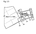
図2.5
ラッピング工程を完了させるために、ラップフィルムは、物品24のパレットの最終隅部周りに張られ、装置は、製造中、切り出し可動台2上に組み込まれたスロット付切断管25に押しつけられた十分なラップフィルム幅を有するように配置される。
Figure 2.5
In order to complete the lapping process, the wrap film is stretched around the final corner of the pallet of the
図2.6
切断刃27は2つのロッドビレットの間に取り付けられており、一方はスロット付切断管25の外側28にあり、他方はスロット付切断管29内にあり、それらの間に切断刃がむき出しの端部27を上方に向けて、かつスロット付切断管のスロットを通るスロット付切断管25に沿って上下にスライド26することができる。カッタは、ケーブル31を介してカッタ及びビレットロッドアセンブリに取り付けられるスロット付切断管の上部で、こぶ付ノブ30を上方に引き上げることによりスロット付カッタ管に沿って上げられる。伸ばしたラップフィルムをカッタ管のスロット25に対して平坦に配置して、カッタの刃27がスロットに沿って上昇し、このようにしてラップフィルム32を切断する。
Fig. 2.6
The
カッタのラップされた物品側にあるフィルムは落ちるか、あるいはパレットの物品周りにラップされたフィルムに押しつけて付着し、かつカッタのラップロール側にあるフィルム端部はその周りでフィルムが切り出し可動台から出る縦のローラ33と、その間に短いラップフィルム36が、次に別の物品を巻き始めるとき、即座に復旧するために挟まれているつまみ点を作成するために、台上のローラと圧接するゴム34の組み込まれた小片との間に保持される。
The film on the wrapped article side of the cutter falls or sticks to and adheres to the film wrapped around the pallet article, and the film edge on the wrap roll side of the cutter cuts the film around it and the movable table The
図3
装置切り出し可動台のアセンブリ及び機能/上部ラップロールブレーキ/エンドキーパ及び下部ブレーキハンドル
FIG.
Assembly and function of movable-out movable platform / upper lap roll brake / end keeper and lower brake handle
切り出し可動台1は、いくつかの機能を支持する水平上板20及び下板21と、関連する機能を有する縦の接続部とからなる。上板20は固定ラップロールブレーキ突起(prong)23と、この制御ハンドル内に、手動旋回ラップロールブレーキレバー24と統合された対抗する第2のブレーキ突起(prong)25とを含む主制御ハンドル22を支持する。
The cutting
上板はまた、釣り合いのとれた吊り上げ点を含み、切断管上部支持ブラケット13と、ラップフィルムがその周りに切り出される縦ラップ幅ローラ管28のためのベアリング台27を取り付けるための孔26とを含む。
The top plate also includes a balanced lifting point and includes a cut tube
切り出し可動台の下板は、縦ラップ幅ローラ管を支持するためにベアリング台ボルト29を取り付ける対応する孔と、下部切断管支持ブラケット30と、その上及びその周りに典型的なラップロール厚紙芯47の下端部が配置されるラップロール芯支持ハブ31と、下部ラップロールブレーキ33用の旋回点として、下板20の下方に折り返された側の一端の2つの孔32とを有する。
The lower plate of the movable cutting table has a corresponding hole for mounting the
上部及び下部切り出し可動台板間には、台主管又はチャネル34、接続管があり、上部及び下部台板35の釣り合いのとれた吊り上げ点間には、正面左縦の角度36、切り出し可動台上部板及び下部板の各々に取り付けられる上部切断管ブラケット26及び下部切断管ブラケット30間に組み込まれる切断管37がある。
Between the upper and lower cutout movable base plates, there is a main table or
装置組付けの間、その間に左手装置フレーム管2が挿入される台主管又はチャネル34は、切り出し可動台構造にとって最も堅固で重要である。
The table main tube or
上板及び下板の釣り合いのとれた吊り上げ点13の接続管35は、その中に吊り上げアイボルト39又はプーリが直接固定されるネジ切りナットを含む。
The connecting
その上に金属片39が固定され、かつその下に金属片が固定される台正面左角度36、50mm又は好適には広幅のゴム片40の左縦端部、その右縦端部は、柔軟な挟み点41を提供する縦ラップ幅ローラ管28に向かって湾曲し、かつ一掃し、その間をラップフィルム43が物品をラップするために通過し、ラップカッタ44により切断された後、弛んだフィルム端部43を利用しやすく保持する。
A
縦ラップ幅ローラ管28は挿入され、上部及び下部45に保持されるベアリングを有し、上部板27の孔を通り下がるベアリング取り付けボルトと、切り出し可動台の下板を通る対応する孔29から上がる対応するベアリング取り付けボルトとの間の切り出し可動台に取り付けられる。
The vertical wrap
ラップ切断管37は、切り出し可動台1の上板20及び下板21各々に組み込まれる上部及び下部切断管支持ブラケット26及び30間に保持される。
The
図4
装置上部ラップロールブレーキハンドル
切り出し可動台上板20上に配置される主制御ハンドル22からの下がるものは、2つのラップロールブレーキ突起23のうち固定されたものである。第2のブレーキ突起25は、制御ハンドル22内に旋回するブレーキレバー24上に組み込まれる。
FIG.
Upper part lap roll brake handle The lower part from the main control handle 22 arranged on the movable movable table
オペレータの手によりブレーキレバーが制御ハンドル内に挟まれると45、ロールが切り出し可動台21の下板上で、ブレーキ突起周りを上向きに正しく、かつラップロールハブ31周りを下向きに正しく取り付けられると48、ブレーキ突起はその中を下方に突出するラップロール厚紙芯47の上端部内に伸張する46。ラップロール芯47内のブレーキ突起23及び25の伸長は、ラップの張りが必要とされると、ロールから引き出されるラップフィルムの広がる動きを遅らせるか、あるいは停止させる。ブレーキレバー24の絞り45に関して達成される張り感、及び積荷周りの装置のてこの作用は、ラップの十分な伸びを判定する情報をオペレータに提供する。
When the brake lever is pinched in the control handle by the operator's
図5
装置下部ラップロールブレーキハンドル
下部切り出し可動台板1に組み付けられるものは、オペレータの肩の高さに近づく、又は超える積荷周りのラッピング旋回のため、上部ブレーキハンドルを用いて、ラッピング工程がラップロールを遅らせたり、止めたりする厄介な高さに上げるとき、上部ラップロールブレーキハンドルの代替である下部ラップロールブレーキハンドル2である。下部ラップロールブレーキハンドル2は金属の屈曲片を具え、一端部は水平位置3でハンドルを形成し、他端部は下部切り出し板1の開口を通して正しく設置される場合、ラップロール厚紙芯が配置される上かつ周りのラップロール支持ハブ5を形成する製造中に組み込まれる短い筒状の突起内で上方に曲げられる4。下部ブレーキハンドルは、製造中、下部ラップロールブレーキハンドル2に取り付けられる軸6に関して旋回し、軸6の各端部は、支点10を提供するために下部台板の下方屈曲端部9内に組み込まれる2つの孔7及び8を通り伸張する。
FIG.
Lower lap roll brake handle The lower cut-out
図6
下部ラップロールブレーキハンドル操作
支点を介して下方圧力11を下部ラップロールブレーキハンドル2にかけることは、ハンドルの上方に屈曲した部分を側方12に動かし、芯が切り出しラップロール支持ハブ5上に正しく配置される場合、ラップロールの厚紙芯14の下方端部内側に接触圧13をかける。
FIG.
Lower lap roll brake handle operation Applying the
この下部ラップロールブレーキハンドルの使用は、ロールから引き出されるフィルムの広がり動作を生じさせ、切り出し可動台の旋回動作を遅らせたり、停止させたりし、次いで人間工学的に高さが増した伸ばし張力を提供するラッピング工程中、ラップされるパレットの隅部の遠い側と接触するガイドローラ周りに生じさせる切り出し可動台の旋回動作を生じさせる。 The use of this lower wrap roll brake handle causes the spreading action of the film drawn from the roll, delays or stops the turning movement of the cutting platform, and then increases the ergonomically increased stretching tension. During the lapping process to be provided, a pivoting motion of the cutout movable table is generated that occurs around the guide roller that contacts the far side of the corner of the pallet to be wrapped.
図7
装置ラップフィルムカッタ及びラップフィルムエンドキーパ
ラップフィルムカッタはラッピング作業完了時、ラップフィルムを介する切断手段として装置に含まれる。好適な実施例において、カッタが上を向き、かつ切断管のスロットに向かって傾く尖った切断刃が取り付けられる傾き平行四辺形状27の刃を含み、これは部分的に収納され、ラップフィルムに対する剪断動作に影響を及ぼすように操作される。
FIG.
The apparatus wrap film cutter and the wrap film end keeper The wrap film cutter is included in the apparatus as a cutting means through the wrap film when the lapping operation is completed. In a preferred embodiment, it includes an
安全な切断刃27は2つのロッドビレット間に取り付けられ、一方はスロット付切断管25の外側28にあり、他方は切断管29内にあり、これらは上向き切断刃がそれらの間に端部27をさらしてスロット付切断管25に沿って上下26に滑らせることができる。カッタは細いケーブル31を介してカッタアセンブリに取り付けられる切断管の上部で、ローレットノブ30で上方に引っ張ることにより切断管に沿って上げられる。伸びたラップフィルムを切断管のスロット25に対して平坦に配置して、切断刃27はラップフィルム32を切断するためにスロットに沿って上昇する。切断管の外側の切断刃27に取り付けられたロッドビレット28間の距離は、それと切断管との間を通過するためにフィルムに十分な空間を有するが、指が刃27に触れることができるような十分な空間はない。
A
一旦切断されたフィルム、即ち、カッタの巻かれた物品側は落下、又はパレット上の物品周りに巻かれたフィルムに対して押しつけられ、かつ貼り付き、フィルム端部、即ち、カッタのラップロール側は、その周りにフィルムが切り出し可動台に出る縦ローラ33と、その間に短いラップフィルム36が別の物品を巻き始めるべく迅速に回復させるために挟まれる挟み点35を作成するために、台上のローラと圧接する組み込まれたゴム片34との間に保持される。切断管は次いで、ローレットノブに接続されたケーブルによって下げられると切断管内を下降する。
Once cut the film, i.e. the side of the article on which the cutter is wound, falls or is pressed against and stuck to the film wound around the article on the pallet, the film end, i.e. the wrap roll side of the cutter In order to create a
図8
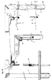
装置高さ制御ハンドル及び支持ケーブル
切り出し可動台1を支持する手段は、それに沿って切り出し管が縦に動く、左正方形圧延中空部RHSフレーム管2に沿って調節可能な高さで、2つの高さ制御ハンドル3.1及び3.2に取り付けられた吊り上げケーブルによって可能となる。この2つの高さ制御ハンドル3.1及び3.2は、装置の3つのフレーム管の正面中央4及び右5に設定される正方形のRHS装置フレーム管に沿って配置される。
FIG.
Device height control handle and support cable The means for supporting the slicing
吊り上げケーブル6は、第1、又は最も近い高さ制御ハンドル3.1に取り付けられ、かつ製造中、組み込まれるフック8を介してフレーム上に固定される第1のプーリ7上、及び上方で装着される。ケーブルは次いで、製造中、フレームクロス管11上に組み込まれる一対のプーリフック10の一方に固定される、即ち、一対のプーリフック10直下の切り出し可動台1の上部に提供された吊り上げ点13の実質的に上部である第2のプーリ9に向かって水平にガイドされる。
The lifting
ケーブルは次いで、装置の切り出し可動台1の上部の吊り上げ点13に固定される第3のプーリ12へと下方に向けられて通され、そこから次いで、製造中、装置フレームクロス管11上に取り付けられる一対のフック10に固定される一対のプーリの他方である第4のプーリ14へと上方に向けられて通される。
The cable is then routed downwardly through a
吊り上げケーブル6は第4のプーリ14から通され、装置の3つのフレーム管の正面中央のフレーム管19を装置の主クロス管11に取り付ける、より短い前方を向くクロス管18下の、製造中に組み込まれるフック17に固定される第5のプーリ15に向かって横切る。
The
ケーブルは第5のプーリ15から第2のプーリへと下方に導かれ、正面中央のフレーム管19に沿って取り付けられる最も高い制御ハンドル3.2へと進む。
The cable is guided downward from the
双方の高さ制御ハンドル3.1及び3.2は、可動台1の釣り合いのとれた吊り上げ点13に取り付けられる切り出し可動台中央プーリ12の何れかの吊り上げケーブル6を上げ下げする。ケーブルが高さ調節ハンドル3.1及び3.2の何れかで引き下げられると、このプーリ周りを折り返され、切り出し可動台を持ち上げ、プーリを半分の速度=50%で加え、何れかのハンドルは下方に引っ張られ=100%、従って、片手で下方に引っ張る作動力により、何れかの高さの制御ハンドルで実現される場合、切り出し可動台の重さとラップロールフィルムとが半分の重さである2:1の割合で、典型的な滑車装置の操作を介する。
Both height control handles 3.1 and 3.2 raise and lower one of the
好適な実施例において、切り出し可動台を持ち上げる高さ制御ハンドルを接続するために選択されるケーブルは、損傷のないプラスチックコートされたタイプであり、触れるには安全であり、かつ切り出し可動台及び完全なラップロールの重さを吊すには十分な大きさである。 In a preferred embodiment, the cable selected to connect the height control handle that lifts the slicing platform is an undamaged plastic coated type, safe to touch, and fully It is large enough to suspend the weight of a simple wrap roll.
図9
装置の高さ制御ハンドル位置固定及び解放
図9.1
各高さ制御ハンドルは、製造中、組み込まれる正方形の孔3を含むハンドルのより広い部分2から延在する操作性ハンドルグリップ1を有する平板からなり、その上及びそれに沿ってフレーム管がセットされる同じ方向にスライド及び留まる孔は、正方形のフレーム管4よりもわずかに大きい。
FIG.
Device height control handle position fix and release Figure 9.1
Each height control handle consists of a flat plate having an
図9.2
各高さ制御ハンドルは、何れかのハンドルが水平5に保持されるとき、縦フレーム管に沿って自由に動くことができるが、水平から上方6又は下方7の何れかの角度の場合は動かない。
Fig. 9.2
Each height control handle is free to move along the vertical frame tube when either handle is held at horizontal 5 but will move if it is at an
本質的にこのような再配置可能な固定手段の簡易な記載は、テントロープ(tent rope)アジャスタペグであり、これはロープからオフセットであるアジャスタにかかる張力が、アジャスタペグに角度を持たせるとき、その上をスライドできるようにロープに沿って縛り、このようにしてアジャスタペグの孔を通過するロープに結ぶ。 In essence, a simple description of such a repositionable fastening means is a tent rope adjuster peg, when the tension on the adjuster that is offset from the rope causes the adjuster peg to angle. Then, tie it along the rope so that it can slide on it, and thus tie it to the rope that passes through the hole in the adjuster peg.
装置の高さ制御ハンドルの何れかは、角度がつけられると6、フレーム管に対してしっかりと固定され、それをさらに力強く動かそうとしても固定されたままである。 Any of the device height control handles 6 are securely fixed to the frame tube when angled, and remain fixed even when trying to move it more forcefully.
図9.3
高さ制御ハンドルが積荷の下に再配置されると、所望の方法で動くことを確かめるために、これらは各々、製造中、組み込まれる2つの突起物を有し、各々は左側面9及び右側面10を含むブックエンド8と似ている。
Fig.9.3
In order to ensure that when the height control handle is relocated under the load, they each have two protrusions that are incorporated during manufacture, each of which has a
図9.2及び図9.3
2つの突起物は各高さ制御ハンドルに取り付けられ、一方はハンドル内の正方形の孔3の上方及び後方11であり、ブックエンドのような突起物13をフレーム管4の後部11に対して平らに滑るように配置するとともに、他方の突起物は高さ制御ハンドル内の正方形の孔3の下及び正面12に取り付けられ、ブックエンドのような突起物13の内側中央面の内側をフレーム管4の正面12に対して平らに滑るように配置する。突起物は、右又は中央正面フレーム管に沿って下方に動くとき、高さ制御ハンドルが水平14より低い角度とならないが、固定動作のためフレーム管に沿って上らないように、各ハンドルが水平15より上の角度となりうる。
Fig. 9.2 and Fig. 9.3
Two projections are attached to each height control handle, one is above and behind 11 the
図9.4
ブックエンドのような突起物9及び10の側面はまた、高さ制御ハンドルが左右に傾かないようにし、これはまた高さ制御ハンドルの正方形の孔3が、それに沿って滑るフレーム管上に固定させる。
Fig. 9.4
The sides of the
図10
装置吊り上げケーブル及び固定高さ制御ハンドルの操作
各切り出し可動台中央プーリ19を介して送られる吊り上げケーブルの各端部は、これらに沿って動くフレーム管4.1及び4.2の中央線からオフセット点で、各高さ制御ハンドル16に接続され、配置されたプーリ20、21、22及び23の上方を介して、吊り上げケーブル上の切り出し可動台吊り上げプーリ19の下向き重量のため、高さ制御ハンドル1及び2上への水平影響15から上方の結束を確実にし、ケーブル16によって引っ張られるとき6、高さ制御ハンドルが上方に角度を持つので、進行に沿った右及び正面中央のフレーム管4.1及び4.2に沿ってどこに再配置されても、双方はフレーム管8に固定する。
FIG.
Operation of the device lifting cable and fixed height control handle Each end of the lifting cable sent through each movable movable
切り出し可動台吊り上げプーリ19で重さの半分を克服するのに十分な手の圧力を高さ制御ハンドル14上に下向きにかけるとき、ハンドルはフレーム管4.1及び4.2上の位置から解かれる5。下方14にかけられるさらなる任意の圧力は、高さ制御ハンドルを下方にスライドさせ、これが異なる位置8で、フレーム管4.1及び4.2上に固定するために、水平15から上方にハンドルの角度を瞬時に変えることができるようにするべく所望の高さが、高さ制御ハンドルを解放することができる点6で得られるまで、吊り上げケーブル及びプーリを介して切り出し可動台吊り上げプーリ19を持ち上げる。
When applying enough hand pressure on the height control handle 14 to overcome half of the weight with the slidable
切り出し可動台を下げるために、各フレーム管4.1及び4.2上の高さ制御ハンドルの固定8を無効にする水平5レベルまで十分な手の圧力が高さ制御ハンドルに下向き14にかけられる。ハンドル14上の手の圧力がハンドルを水平に保つことができるのに十分である限り、ハンドルの上向きの動きを止めるのには十分ではなく、ハンドルを下方に押すのに十分ではなく、この時点で、高さ制御ハンドルを上向き7に引っ張るために、持ち上げケーブル16に取り付けられる切り出し可動台の上向きの力が可能となる。何れかのハンドル1又は2が解放される6か、あるいはハンドルを各フレーム管上に直ちに固定8する、水平上に角度をなすことができるようになるまで、取り付けられた中央プーリ19を介して切り出し可動台は、何れかの高さ制御ハンドル1が右又は正面中央フレーム管4.1及び4.2上を上昇することができるので、左フレーム管3に沿って下降する。
Sufficient hand pressure is applied to the height control handle downwards 14 to the horizontal five levels to disable the height control handle lock 8 on each frame tube 4.1 and 4.2 to lower the slicing platform. . As long as the pressure of the hand on the
ブックエンドタイプの突起物11及び12は、切り出し可動台持ち上げプーリ19を実質的に吊り上げるために押し下げられる14とき、また高さ制御ハンドルを上げて左フレーム管3に沿って切り出し可動台を下げるとき、オペレータが感じる水平の基準とともにフレーム管の高さ制御ハンドルの拘束を解く。
When the bookend-
図11.1
装置ベース
好適な実施例において、装置用ベースは、アセンブリ及び耐久性の機能の目的のために、製造中、組み込まれる孔又は湾曲を有する鋼の筋違い及び要素からなる。
Figure 11.1
Device Base In a preferred embodiment, the device base consists of steel streaks and elements with holes or curvatures that are incorporated during manufacture for purposes of assembly and durability functions.
左ベース金属要素1は、水平な平面部2として開始し、次いで下方3に角度がつけられ、次いで水平な平面4であり、次いで上方5に角度がつけられ、次いで第1の部分と同じ高さの水平な平面6である。
The left
第1及び最後の水平部は、下部7及び8に取り付けられる車輪用であり、2つの下方に角度のついた部分間の下部中間部4は、左手側切り出し可動台フレーム管10を固定する孔9を含む。
The first and last horizontal portions are for wheels attached to the
左ベース要素1の下部中間部4は、ラップを、ラップされる物品周りに、可能な限り低く好都合に切り出すことができるように固定された左フレーム管10に沿って切り出し可動台をほぼ地上レベルまで下げることができる。
The lower
正面及び後部筋違い11及び12は、ベースの左側要素1をベースの右側要素13に接続する。この右側要素に沿って、右16及び中央正面17装置フレーム管を固定する2つの孔14及び15がある。右側要素の下には、左側要素と同じ寸法の2つの車輪18及び19が取り付けられる。
Front and
ベース正面左隅部に取り付けられるものは、パレットの側面又はパレットの端部上に配置される、又は張り出す物品に沿って巻く柔軟なガイドローラ20であり、これはまた、提供された発明の使用を通して、ラップフィルムの張りを達成するとき、周りに旋回する、てこの作用を生じさせる損傷のない接触点を提供する。
Attached to the base front left corner is a
好適な実施例におけるベースは、巻かれる典型的なパレットの端部上の装置ガイドローラの高さを配置するのにあまり高くない車輪を含む。 The base in the preferred embodiment includes wheels that are not too high to place the height of the device guide roller on the end of a typical pallet to be wound.
積荷周りに減少した回転抵抗がまた不規則な地面上に機能を提供できるが、より大きな車輪が、非典型的な適用のために取り付けられてもよい。 Although reduced rotational resistance around the load can also provide functionality on irregular ground, larger wheels may be mounted for atypical applications.
図11.2
装置フレーム
左21、正面中央22及び右23の3つからなるフレーム、縦、正方形、RHS巻かれた中空部鋼管、左21及び右23の縦管の上部24を横切る同じ鋼部の別のもの、及び横管23に対して正面中央22縦管に隣接している同じ部分の管のより短い筋違管25とを含み、ベース1のこれらが組み込まれた接地面積の三脚効果を介して、実質的にフレームを縦に補強するためにクロス管23の正面側及びクロス管から十分前方に設定する。
Fig.11.2
Equipment frame Left 21,
フレームは、支持プーリが装置機能に関する製造中に組み込まれる4つのフックを有する。 The frame has four hooks into which the support pulley is incorporated during manufacture for device function.
フレーム管の下端部は、輸送及び保管中、容量を減少させて組み立て及び分解を可能とするべくフレームをベースに取り付ける製造中に組み込まれる内部固定手段を含む。 The lower end of the frame tube includes internal fastening means incorporated during manufacture to attach the frame to the base to reduce capacity and allow assembly and disassembly during transport and storage.
フレームは、適切な耐久性及び組み付けの便宜を提供するために、ボルトで接合されるとともに溶接されている。好適な実施例における材料は、戸外での使用において、耐久性及び長命のために亜鉛メッキ鋼である。
The frames are bolted and welded to provide proper durability and assembly convenience. The material in the preferred embodiment is galvanized steel for durability and long life when used outdoors.
Claims (19)
図1及び図2.2
パレット端部の高さ近くでガイドローラは、各パレット隅部9の遠い側か、あるいは積荷が地面と接触する任意の固定点に向けられる。
これは、てこの作用が得られる点であり、物品10から離れて旋回する装置の切り出し可動台と、フィルムが静止パレットに巻かれる物品12と接触した最終点との間にさらに伸ばされるラップフィルムの広がりを止めるために、制御ハンドル6下に押し込められたラップロールブレーキ11を用いて、パレット隅部10周りの装置のさらなる旋回移動を介して実現される。
図2.3
装置がパレット隅部14周りを約90度で旋回し、次のパレット隅部を目指してフィルムの張られてくっつく性質により、そこで付着する物品16と接触する張られたラップフィルムをすぐに配置する前方15に動かすことができる。
ラップロールブレーキ11が解放されうるこの点で、パレットの次の隅部又は積荷の同様の固定点に近づくまで、その周りの旋回、てこの作用による張り、及び前進を繰り返すことができる。
図2.4
予期された上方らせん回転により、物品17のパレット周りにラップフィルムを切り出すために装置を用いて第1の囲い動作を完了した後、切り出し可動台2は必要とされるラッピングの続くレベルまで上げることができる。
切り出し可動台2のラッピング高さを上げる前に、ある長さのラップ用フィルムが切り出し可動台から引き出され、装置を巻かれる物品から離して21動かすことによって弛められ20、次いで巻かれる物品に戻される。
これにより、前もって切り出されるラップフィルム20の長さを故意に上方に伸ばすことで、前進を妨げることなく切り出し可動台の上昇が可能となる。
切り出し可動台2は次いで、2つの高さ制御ハンドル17.1及び17.2の何れかを介して上げ下げされる。
高さ制御ハンドル17.1又は17.2に取り付けられる何れかの吊り上げケーブル端部は、右18及び正面中央19の縦フレーム管の何れかに沿って下方に引っ張られるとき、吊り上げケーブルに沿って中間に吊り下げされる切り出し可動台2は、プーリを取り付けた中央切り出し可動台周りを通過する吊り上げケーブルの2:1の割合のため、高さ制御ハンドルの何れかが下方に引っ張られる半分の速度で上昇する。
生じたラップ高さが高さ制御ハンドルの調節により得られると、次いで装置ベース上のガイドローラ7が、先のラップ回転まで、てこの作用の張りあたりの、てこの作用点であるパレット22の以下の隅部に向かって、及びその周りに再びガイドされる。記載された囲み、高さを増した切り出し、及びラップフィルム反復の伸びの間、巻かれる物品まわりのラッピングが高さと同じか、又はそれを超えるまで、切り出し可動台が、上部ラップロールブレーキ11を厄介な、又は効果的に操作されるのに届かない高さが増したところに配置されるとき、ラップロール23の下端で切り出し可動台に組み込まれた第2のラップロールブレーキが、ラップフィルムの伸びを停止させる簡単なアクセスの経済的な制御を提供する。パレットへのラッピングの試みを開始することなく前述のラッピング工程は、上部ラップロールブレーキ11の代わりに下部ラップロールブレーキ23を代わりに用いることにより高さで繰り返すことができる。
図2.5
ラッピング工程を完了させるために、ラップフィルムは、物品24のパレットの最終隅部周りに張られ、装置は、製造中、切り出し可動台2上に組み込まれたスロット付切断管25に押しつけられた十分なラップフィルム幅を有するように配置される。
図2.6
切断刃27は2つのロッドビレットの間に取り付けられており、一方はスロット付切断管の外側28にあり、他方はスロット付切断管29内にあり、それらの間に切断刃がむき出しの端部27を上方に向けて、かつスロット付切断管25のスロットを通るスロット付切断管25に沿って上下にスライド26することができる。カッタは、ケーブル31を介してカッタ及びビレットロッドアセンブリに取り付けられるスロット付切断管の上部で、こぶ付ノブ30を上方に引き上げることによりスロット付カッタ管に沿って上げられる。伸ばしたラップフィルムをカッタ管のスロット25に対して平坦に配置して、カッタの刃27はスロットに沿って上昇し、このようにしてラップフィルム32を切断する。
カッタのラップされた物品側にあるフィルムは落ちるか、あるいはパレットの物品周りにラップされたフィルムに押しつけて付着し、かつカッタのラップロール側にあるフィルム端部はその周りでフィルムが切り出し可動台から出る縦のローラ33と、その間に短いラップフィルム36が、次に別の物品を巻き始めるとき、即座に復旧するために挟まれているつまみ点35を作成するために、台上のローラと圧接するゴム34の組み込まれた小片との間に保持される。
装置の3つのフレーム管の正面中央4及び右5に設定される正方形のRHS装置フレーム管に沿って配置される。
吊り上げケーブル6は、第1、又は最も近い高さ制御ハンドル3.1に取り付けられ、かつ製造中、組み込まれるフック8を介してフレーム上に固定される第1のプーリ7上、及び上方で装着される。ケーブルは次いで、製造中、フレームクロス管11上に組み込まれる一対のプーリフック10の一方に固定される、即ち、一対のプーリフック10直下の切り出し可動台1の上部に提供された左点13の実質的に上部である第2のプーリ9に向かって水平にガイドされる。
ケーブルは次いで装置の切り出し可動台1の上部の吊り上げ点13に固定される第3のプーリ12へと下方に向けられ、かつ通され、そこから次いで、製造中、装置フレームクロス管11上に取り付けられる一対のフック10に固定される一対のプーリの他方である第4のプーリ14へと上方に向けられ、かつ通される。
吊り上げケーブル6は第4のプーリ14から通され、装置の3つのフレーム管の正面中央のフレーム管19を装置の主クロス管11に取り付ける、より短い前方を向くクロス管18下の、製造中に組み込まれるフック17に固定される第5のプーリ15に向かって横切る。
ケーブルは第5のプーリ15から第2のプーリへと下方に導かれ、正面中央のフレーム管19に沿って取り付けられる最も高い制御ハンドル3.2へと進む。
双方の高さ制御ハンドル3.1及び3.2は、台1の釣り合いのとれた吊り上げ点13に取り付けられる切り出し可動台中央プーリ12の何れかの側の吊り上げケーブル6を上げ下げする。ケーブルが高さ調節ハンドル3.1及び3.2の何れかで引き下げられると、このプーリ周りを折り返され、切り出し可動台を持ち上げ、プーリを半分の速度=50%で加え、何れかのハンドルは下方に引っ張られ=100%、従って、片手で下方に引っ張る作動力により、何れかの高さの制御ハンドルで実現される場合、切り出し可動台の重さとラップロールフィルムとが半分の重さである2:1の割合で、典型的な滑車装置の操作を介する。
好適な実施例において、切り出し可動台を持ち上げる高さ制御ハンドルを接続するために選択されるケーブルは、損傷のないプラスチックコートされたタイプであり、触れるには安全であり、かつ切り出し可動台及び完全なラップロールの重さを吊すには十分な大きさである。 Using the invention provided in the preferred embodiment, the wrapping is generally set sufficiently low to secure the wrap film to the pallet 3 in order to start and end the pallet wrapping of the article 1 The film is pulled out from the cutting movable stand 2 of the apparatus. The device is then moved forward 4 and parallel 5 along each side of the pallet by the device control handle 6. While the device is moving around the article to be wound, the guide roller 7 attached to the front left corner of the mobile base 8 of the device is steered towards the next pallet corner 9.
1 and 2.2
Near the height of the pallet end, the guide rollers are directed to the far side of each pallet corner 9 or to any fixed point where the load contacts the ground.
This is the point at which the lever action is obtained, and the wrap film is further stretched between the cutting movable stand of the device that turns away from the article 10 and the final point where the film contacts the article 12 wound on the stationary pallet. This is achieved via a further pivoting movement of the device around the pallet corner 10 using a lap roll brake 11 which is pushed under the control handle 6.
Figure 2.3
The device pivots about 90 degrees around the pallet corner 14 and immediately places a stretched wrap film in contact with the adhering article 16 due to the tensioning and sticking nature of the film towards the next pallet corner. It can be moved forward 15.
At this point where the lap roll brake 11 can be released, it is possible to repeat the swivel, tensioning and advancement around it until it approaches the next corner of the pallet or a similar fixed point of the load.
Figure 2.4
After completing the first enclosing operation using the apparatus to cut out the wrap film around the pallet of the article 17 due to the anticipated upward spiral rotation, the cutting movable platform 2 is raised to the level that will follow the required wrapping. Can do.
Before raising the wrapping height of the cuttable 2, a length of wrapping film is pulled out of the cuttable, loosened by moving the device 21 away from the article to be wound 20, and then into the article to be wound. Returned.
As a result, by intentionally extending the length of the wrap film 20 cut out in advance upward, it is possible to raise the cut movable table without hindering forward movement.
The cutout movable platform 2 is then raised and lowered via either of the two height control handles 17.1 and 17.2.
Either lifting cable end attached to the height control handle 17.1 or 17.2 is pulled along the lifting cable when pulled down along either the right frame 18 or the longitudinal frame tube at the front center 19. The cut-out movable base 2 suspended in the middle is a ratio of 2: 1 of the lifting cable passing around the central cut-out movable base with the pulley attached, so that either of the height control handles is pulled at a half speed. To rise.
When the resulting wrap height is obtained by adjusting the height control handle, the guide roller 7 on the machine base is then moved to the pallet 22 which is the point of action of the lever around the tension of the lever until the previous lap rotation. Guided again towards and around the following corners. During the described enclosure, increased height cutout, and wrap film repeat elongation, the cutout carriage can move the upper wrap roll brake 11 until the wrapping around the wound article is equal to or greater than the height. A second lap roll brake cut out at the lower end of the lap roll 23 and incorporated into the movable platform when placed at a height that is cumbersome or not reachable to operate effectively, Provides economical control of simple access to stop stretching. Without starting an attempt to wrap to the pallet, the aforementioned wrapping process can be repeated at height by using the lower lap roll brake 23 instead of the upper lap roll brake 11.
Figure 2.5
In order to complete the lapping process, the wrap film is stretched around the final corner of the pallet of the article 24 and the apparatus is fully pressed against the slotted cutting tube 25 incorporated on the cutting platform 2 during manufacture. Arranged to have a wide wrap film width.
Fig. 2.6
The cutting blade 27 is mounted between two rod billets, one on the outside 28 of the slotted cutting tube and the other in the slotted cutting tube 29 between which the cutting blade is exposed. 27 can be slid up and down 26 along the slotted cutting tube 25 passing through the slot of the slotted cutting tube 25. The cutter is raised along the slotted cutter tube by pulling up the knurled knob 30 above the slotted cutting tube attached to the cutter and billet rod assembly via cable 31. The stretched wrap film is placed flat against the slot 25 of the cutter tube, and the cutter blade 27 rises along the slot, thus cutting the wrap film 32.
The film on the wrapped article side of the cutter falls or sticks to and adheres to the film wrapped around the pallet article, and the film edge on the wrap roll side of the cutter cuts the film around it and the movable table A vertical roller 33 exiting from the roller on the table to create a pinch point 35 that is sandwiched for immediate recovery when a short wrap film 36 is next wound on another article It is held between a small piece in which rubber 34 is pressed.
Arranged along the square RHS device frame tube set at the front center 4 and right 5 of the three frame tubes of the device.
The lifting cable 6 is mounted on the first pulley 7 which is attached to the first or nearest height control handle 3.1 and which is fixed on the frame via an incorporated hook 8 during manufacture and above. Is done. The cable is then secured to one of the pair of pulley hooks 10 incorporated on the frame cross tube 11 during manufacture, i.e. substantially the left point 13 provided on the upper part of the movable movable platform 1 just below the pair of pulley hooks 10. Are guided horizontally toward the second pulley 9 which is the upper part.
The cable is then directed downward and passed through a third pulley 12 that is fixed to a lifting point 13 at the top of the machine's cutting platform 1 from which it is then mounted on the equipment frame cross tube 11 during manufacture. The fourth pulley 14, which is the other of the pair of pulleys fixed to the pair of hooks 10, is directed upward and passed therethrough.
The lift cable 6 is threaded from the fourth pulley 14 and attaches a frame tube 19 in the center of the front of the three frame tubes of the device to the main cross tube 11 of the device, under the shorter forward cross tube 18 during manufacture. It crosses toward the fifth pulley 15 fixed to the hook 17 to be incorporated.
The cable is guided downward from the fifth pulley 15 to the second pulley and proceeds to the highest control handle 3.2 attached along the frame tube 19 in the center of the front.
Both height control handles 3.1 and 3.2 raise and lower the lifting cable 6 on either side of the movable movable table central pulley 12 attached to the balanced lifting point 13 of the table 1. When the cable is pulled down by either of the height adjustment handles 3.1 and 3.2, it is folded around this pulley, the cutting movable base is lifted, and the pulley is added at half speed = 50%. Pulled downward = 100%, therefore, when realized with a control handle of any height with an actuation force pulling downward with one hand, the weight of the movable carriage and the wrap roll film are half the weight. Through operation of a typical pulley system at a ratio of 2: 1.
In a preferred embodiment, the cable selected to connect the height control handle that lifts the slicing platform is an undamaged plastic coated type, safe to touch, and fully It is large enough to suspend the weight of a simple wrap roll.
2. The device according to claim 1, wherein a cable or applicable strand is used that is guided on and around the pulley to apply or break the force that exerts the effect exerted by the operator.
Applications Claiming Priority (3)
| Application Number | Priority Date | Filing Date | Title |
|---|---|---|---|
| AU2009902017A AU2009902017A0 (en) | 2009-05-08 | Dispensing apparatus | |
| AU2009902017 | 2009-05-08 | ||
| PCT/AU2010/000555 WO2010127412A1 (en) | 2009-05-08 | 2010-05-07 | Dispensing apparatus |
Publications (2)
| Publication Number | Publication Date |
|---|---|
| JP2012526018A true JP2012526018A (en) | 2012-10-25 |
| JP2012526018A5 JP2012526018A5 (en) | 2013-06-27 |
Family
ID=43049858
Family Applications (1)
| Application Number | Title | Priority Date | Filing Date |
|---|---|---|---|
| JP2012508857A Pending JP2012526018A (en) | 2009-05-08 | 2010-05-07 | Cutting device |
Country Status (7)
| Country | Link |
|---|---|
| US (1) | US8938939B2 (en) |
| EP (1) | EP2427379A4 (en) |
| JP (1) | JP2012526018A (en) |
| CN (1) | CN103153794B (en) |
| AU (1) | AU2010244984A1 (en) |
| CA (1) | CA2761063C (en) |
| WO (1) | WO2010127412A1 (en) |
Cited By (3)
| Publication number | Priority date | Publication date | Assignee | Title |
|---|---|---|---|---|
| KR20180007391A (en) * | 2016-07-12 | 2018-01-23 | 김성연 | Manual vinyl film wrapping apparatus |
| KR20190115951A (en) * | 2018-04-04 | 2019-10-14 | 이욱우 | Manual wrapping device |
| KR20210084486A (en) * | 2018-11-01 | 2021-07-07 | 엔트로테크 아이엔씨 | Methods and apparatus for applying polymeric films and laminates to the surface of articles |
Families Citing this family (44)
| Publication number | Priority date | Publication date | Assignee | Title |
|---|---|---|---|---|
| WO2009154997A1 (en) * | 2008-05-28 | 2009-12-23 | Lantech.Com, Llc | Film clamp and related methods and apparatuses for wrapping loads |
| US20100314483A1 (en) * | 2009-06-15 | 2010-12-16 | Rain Bird Corporation | Method and Apparatus for Dispensing Tubing |
| EP2709911B1 (en) * | 2011-05-09 | 2015-04-01 | Robopac S.p.A. | Self-propelled wrapping machine |
| FI20116311A (en) * | 2011-12-22 | 2013-06-23 | Illinois Tool Works | wrapping machine |
| US11066198B2 (en) * | 2012-06-18 | 2021-07-20 | TAB Industries, LLC | Stretch film dispenser for orbital pallet wrappers |
| WO2014127124A1 (en) | 2013-02-13 | 2014-08-21 | Lantech.Com, Llc | Containment force-based wrapping |
| US9248952B2 (en) | 2013-03-13 | 2016-02-02 | Rain Bird Corporation | Dispenser for conduit, related components, and tools |
| US20140263526A1 (en) * | 2013-03-14 | 2014-09-18 | Hsiu-Man Yu Chen | Vertical packaging wrap cutter |
| US20150197361A1 (en) * | 2013-03-14 | 2015-07-16 | Hsiu-Man Yu Chen | Vertical cutter for wrapping material |
| CA2906954A1 (en) * | 2013-03-15 | 2014-09-18 | Groupe Anderson Inc. | Wrapping device and method of operation thereof |
| CA3111412C (en) | 2014-01-14 | 2023-08-08 | Lantech.Com, Llc | Dynamic adjustment of wrap force parameter responsive to monitored wrap force and/or for film break reduction |
| US10023334B2 (en) | 2014-03-17 | 2018-07-17 | Marvin B. Schwartz | Full motion wrapping apparatus |
| US9821335B2 (en) | 2014-04-08 | 2017-11-21 | Rain Bird Corporation | Irrigation system |
| WO2016057723A1 (en) | 2014-10-07 | 2016-04-14 | Lantech.Com, Llc | Projecting containment force for load wrapping apparatus |
| US20160200467A1 (en) * | 2015-01-08 | 2016-07-14 | Neil G. Cousins | Portable stretch wrapping machine |
| DE102015101489A1 (en) | 2015-02-02 | 2016-08-04 | Signode Industrial Group Llc | Packaging device and method of operating the same |
| EP3838775A3 (en) | 2015-04-10 | 2021-09-29 | Lantech.com, LLC | Stretch wrapping machine supporting top layer containment operations |
| CN104943906B (en) * | 2015-05-26 | 2017-07-04 | 苏州嘉俊奥特威工业自动化有限公司 | Go out membranous system with identical tension prestretching on one kind winding film packing machine |
| SMP201500193B (en) * | 2015-08-07 | 2017-03-08 | Busca Andrea Ing | SELF PROPELLED WINDING MACHINE AND SYSTEM AND WINDING METHOD |
| EP3353063B1 (en) | 2015-09-25 | 2021-04-07 | Lantech.Com LLC | Stretch wrapping machine with automated determination of load stability by subjecting a load to a disturbance |
| CN106314841B (en) * | 2016-08-30 | 2018-11-09 | 江苏华航威泰机器人科技有限公司 | A kind of thin film winding machine |
| US11013183B2 (en) | 2017-03-03 | 2021-05-25 | Deere & Company | Bale wrap mechanism |
| US10765068B2 (en) * | 2017-03-03 | 2020-09-08 | Deere & Company | Bale wrap mechanism |
| US11006581B2 (en) | 2017-03-03 | 2021-05-18 | Deere & Company | Bale wrap mechanism |
| US20180257805A1 (en) * | 2017-03-07 | 2018-09-13 | Daryl L. Baer | Stretch wrapping machine and method of stretch wrapping |
| EP3684698B1 (en) | 2017-09-22 | 2023-11-15 | Lantech.com, LLC | Load wrapping apparatus wrap profiles with controlled wrap cycle interruptions |
| CN108557138A (en) * | 2018-04-26 | 2018-09-21 | 芜湖金茂包装制品有限公司 | Pellet type winds film packing machine |
| US11820537B2 (en) | 2018-08-01 | 2023-11-21 | Alpine Marketing International, Inc. | Variable height stretch wrap machine |
| IT201800010079A1 (en) * | 2018-11-06 | 2020-05-06 | Atlanta Stretch S P A | EQUIPMENT FOR WINDING PRODUCTS WITH A FILM OF WINDING MATERIAL |
| CN109606824B (en) * | 2018-12-26 | 2020-10-16 | 佛山道斯水溶包装技术有限公司 | Base structure of packaging film on film winding packaging machine |
| US10961006B2 (en) * | 2019-01-16 | 2021-03-30 | Clinton Young | Film wrap dispensing device |
| IT201900002869A1 (en) * | 2019-02-27 | 2020-08-27 | Robopac Spa | SELF-PROPELLED WRAPPING MACHINE AND WINDING METHOD |
| CA3147094A1 (en) | 2019-09-09 | 2021-03-18 | Lantech.Com, Llc | Stretch wrapping machine with dispense rate control based on sensed rate of dispensed packaging material and predicted load geometry |
| US11643229B2 (en) * | 2019-09-12 | 2023-05-09 | Cousins Packaging Inc. | Portable wrapping machine |
| US11518557B2 (en) | 2019-09-19 | 2022-12-06 | Lantech.Com, Llc | Packaging material grading and/or factory profiles |
| CN111959847A (en) * | 2020-08-10 | 2020-11-20 | 昆山步惠机械设备有限公司 | Automatic winding and packaging equipment and production process |
| CN112193471A (en) * | 2020-10-22 | 2021-01-08 | 浙江格锐特包装材料有限公司 | Automatic packaging equipment for small and medium-sized express cartons |
| PT4015406T (en) * | 2020-12-18 | 2023-10-23 | Msk Verpackung Syst Gmbh | Device and method for introducing an opening into a partial region of a film wrapping of a stack of goods, preferably arranged on a pallet, the film wrapping preferably being designed as a film cover pulled over the stack of goods or as a film strap at least partially surrounding the stack of goods |
| CN113002833B (en) * | 2021-02-26 | 2022-06-10 | 福建恒安集团有限公司 | Safe film interrupting mechanism and film interrupting method thereof |
| USD995589S1 (en) * | 2021-08-06 | 2023-08-15 | Robopac S.P.A. | Packaging machine |
| KR102644693B1 (en) * | 2021-09-24 | 2024-03-06 | 정찬오 | Manual type wrapping apparatus for packaging |
| CN114604456B (en) * | 2022-02-18 | 2024-03-08 | 山东大宏智能设备股份有限公司 | Refractory brick packaging technology |
| WO2024044834A1 (en) * | 2022-08-31 | 2024-03-07 | Auger Theotim | Method and device for password generation |
| KR102679384B1 (en) * | 2024-02-06 | 2024-07-02 | 조성빈 | Driving device of hand wrapping machine |
Citations (5)
| Publication number | Priority date | Publication date | Assignee | Title |
|---|---|---|---|---|
| JPS55123405U (en) * | 1979-02-26 | 1980-09-02 | ||
| JPH0595802U (en) * | 1991-12-11 | 1993-12-27 | 王子製袋株式会社 | Stretch wrapping machine |
| JP3013715U (en) * | 1995-01-18 | 1995-07-18 | 王子製袋株式会社 | Automatic stretch wrapping machine |
| JP2002362509A (en) * | 2001-06-06 | 2002-12-18 | Yamakawa Engineering Kk | Packaging machine |
| JP2006321506A (en) * | 2005-05-17 | 2006-11-30 | Yamakawa Engineering Kk | Top face cover attaching method, and top face cover attaching machine used for this method |
Family Cites Families (15)
| Publication number | Priority date | Publication date | Assignee | Title |
|---|---|---|---|---|
| US369614A (en) * | 1887-09-06 | pullin | ||
| US3495375A (en) * | 1967-04-20 | 1970-02-17 | Anchor Hocking Corp | Stabilizing unit loads using tensioned film |
| US4067174A (en) * | 1976-12-20 | 1978-01-10 | Joseph Goldstein | Stretch wrap machine |
| US4209961A (en) * | 1978-10-11 | 1980-07-01 | Stevenson Industries | Guide mechanism for self-guiding stretch-wrap machine |
| US4369614A (en) | 1980-11-17 | 1983-01-25 | Tetzner Siegfried K | Wrapping apparatus |
| SE446714B (en) * | 1984-11-26 | 1986-10-06 | Kjell Erik Wilhelmsson | SET UP WITH HYDRAULIC PUMP SHOOTING A LIFT ON A LIFTING AND LIFTING DEVICE FOR EXECUTING THE SET |
| JPH0298529A (en) * | 1988-06-29 | 1990-04-10 | Asahi Chem Ind Co Ltd | Manufacture of package using stretch wrapping film |
| FI82010C (en) * | 1988-11-30 | 1991-01-10 | Pesmel Insinoeoeritoimisto | Device combination in a packaging machine |
| FR2727075A1 (en) * | 1994-11-21 | 1996-05-24 | F Mortelette Ets | Manually driven device for helicoidally wrapping e.g. pallet load with plastics film |
| US6526734B1 (en) | 2001-09-07 | 2003-03-04 | Illinois Tool Works Inc. | Portable plastic film wrapping system |
| US6742322B2 (en) * | 2002-04-12 | 2004-06-01 | Illinois Tool Works Inc. | Portable plastic film wrapping system |
| CA2402670A1 (en) * | 2002-09-11 | 2004-03-11 | Artemio Mazzarolo | Wrapping machine |
| CN1209256C (en) * | 2002-11-19 | 2005-07-06 | 黄汉卿 | Hand dragging device for ship |
| US7051492B2 (en) | 2003-12-15 | 2006-05-30 | Illinois Tool Works Inc. | Film wrapping apparatus with negator spring biasing members |
| US7437863B2 (en) | 2005-11-02 | 2008-10-21 | Moser Robert E | Wrap dispensing apparatus |
-
2010
- 2010-05-07 US US13/318,990 patent/US8938939B2/en active Active
- 2010-05-07 AU AU2010244984A patent/AU2010244984A1/en not_active Abandoned
- 2010-05-07 CA CA2761063A patent/CA2761063C/en not_active Expired - Fee Related
- 2010-05-07 JP JP2012508857A patent/JP2012526018A/en active Pending
- 2010-05-07 EP EP10771914.8A patent/EP2427379A4/en not_active Withdrawn
- 2010-05-07 WO PCT/AU2010/000555 patent/WO2010127412A1/en active Application Filing
- 2010-05-07 CN CN201080030596.XA patent/CN103153794B/en active Active
Patent Citations (5)
| Publication number | Priority date | Publication date | Assignee | Title |
|---|---|---|---|---|
| JPS55123405U (en) * | 1979-02-26 | 1980-09-02 | ||
| JPH0595802U (en) * | 1991-12-11 | 1993-12-27 | 王子製袋株式会社 | Stretch wrapping machine |
| JP3013715U (en) * | 1995-01-18 | 1995-07-18 | 王子製袋株式会社 | Automatic stretch wrapping machine |
| JP2002362509A (en) * | 2001-06-06 | 2002-12-18 | Yamakawa Engineering Kk | Packaging machine |
| JP2006321506A (en) * | 2005-05-17 | 2006-11-30 | Yamakawa Engineering Kk | Top face cover attaching method, and top face cover attaching machine used for this method |
Cited By (6)
| Publication number | Priority date | Publication date | Assignee | Title |
|---|---|---|---|---|
| KR20180007391A (en) * | 2016-07-12 | 2018-01-23 | 김성연 | Manual vinyl film wrapping apparatus |
| KR101867676B1 (en) * | 2016-07-12 | 2018-06-15 | 김성연 | Manual vinyl film wrapping apparatus |
| KR20190115951A (en) * | 2018-04-04 | 2019-10-14 | 이욱우 | Manual wrapping device |
| KR102122858B1 (en) * | 2018-04-04 | 2020-06-15 | 이욱우 | Manual wrapping device |
| KR20210084486A (en) * | 2018-11-01 | 2021-07-07 | 엔트로테크 아이엔씨 | Methods and apparatus for applying polymeric films and laminates to the surface of articles |
| KR102709160B1 (en) * | 2018-11-01 | 2024-09-23 | 피피지 어드밴스드 서피스 테크놀로지스, 엘엘씨 | Method and device for applying polymer films and laminates to the surface of articles |
Also Published As
| Publication number | Publication date |
|---|---|
| US20120042615A1 (en) | 2012-02-23 |
| AU2010244984A1 (en) | 2011-12-15 |
| CN103153794B (en) | 2015-10-21 |
| WO2010127412A1 (en) | 2010-11-11 |
| CN103153794A (en) | 2013-06-12 |
| EP2427379A1 (en) | 2012-03-14 |
| EP2427379A4 (en) | 2016-03-23 |
| CA2761063C (en) | 2017-07-25 |
| CA2761063A1 (en) | 2010-11-11 |
| US8938939B2 (en) | 2015-01-27 |
Similar Documents
| Publication | Publication Date | Title |
|---|---|---|
| JP2012526018A (en) | Cutting device | |
| US20060219836A1 (en) | Adjustable height coil dispenser | |
| CN107399345B (en) | Trolley and the method for operating trolley | |
| US9969411B2 (en) | Hand truck | |
| US6526734B1 (en) | Portable plastic film wrapping system | |
| US6742322B2 (en) | Portable plastic film wrapping system | |
| US10308382B2 (en) | Method for applying an underlayment layer to trucking cargo | |
| US7051492B2 (en) | Film wrapping apparatus with negator spring biasing members | |
| JP2012526018A5 (en) | ||
| CA2516853C (en) | Tarp loading structure and method for using same | |
| US20060245889A1 (en) | Device and method for manipulating rolled materials | |
| US6991195B2 (en) | Wrapping apparatus | |
| CN219584219U (en) | Flowerpot handling device | |
| US8578847B2 (en) | Apparatuses and methods for fluid evacuation | |
| US20200023874A1 (en) | Rolling Lever Dumbbell Handcart Method | |
| ITRN20000028A1 (en) | APPARATUS FOR BANDING PALLETIZED LOADS WITH PLASTIC FILM, PRE-STRETCHED | |
| CA2967605A1 (en) | Apparatus and method for loading a truck | |
| IE912198A1 (en) | A method and apparatus for supporting an article during packing | |
| CA2440524A1 (en) | Wrapping apparatus | |
| HU4685U (en) | Elevator for hives | |
| IES84205Y1 (en) | A keg lifting apparatus |
Legal Events
| Date | Code | Title | Description |
|---|---|---|---|
| A521 | Request for written amendment filed |
Free format text: JAPANESE INTERMEDIATE CODE: A523 Effective date: 20130507 |
|
| A621 | Written request for application examination |
Free format text: JAPANESE INTERMEDIATE CODE: A621 Effective date: 20130507 |
|
| A521 | Request for written amendment filed |
Free format text: JAPANESE INTERMEDIATE CODE: A523 Effective date: 20130903 |
|
| A131 | Notification of reasons for refusal |
Free format text: JAPANESE INTERMEDIATE CODE: A131 Effective date: 20140325 |
|
| A521 | Request for written amendment filed |
Free format text: JAPANESE INTERMEDIATE CODE: A523 Effective date: 20140625 |
|
| A02 | Decision of refusal |
Free format text: JAPANESE INTERMEDIATE CODE: A02 Effective date: 20141007 |