JP2012522194A - Wired drill pipe with improved structure - Google Patents
Wired drill pipe with improved structure Download PDFInfo
- Publication number
- JP2012522194A JP2012522194A JP2012502479A JP2012502479A JP2012522194A JP 2012522194 A JP2012522194 A JP 2012522194A JP 2012502479 A JP2012502479 A JP 2012502479A JP 2012502479 A JP2012502479 A JP 2012502479A JP 2012522194 A JP2012522194 A JP 2012522194A
- Authority
- JP
- Japan
- Prior art keywords
- guide tube
- hole
- drill string
- element according
- string element
- Prior art date
- Legal status (The legal status is an assumption and is not a legal conclusion. Google has not performed a legal analysis and makes no representation as to the accuracy of the status listed.)
- Pending
Links
- XLYOFNOQVPJJNP-UHFFFAOYSA-N water Substances O XLYOFNOQVPJJNP-UHFFFAOYSA-N 0.000 claims description 14
- 238000005304 joining Methods 0.000 claims description 11
- 238000007789 sealing Methods 0.000 claims description 10
- 230000002093 peripheral effect Effects 0.000 claims description 6
- 229920002994 synthetic fiber Polymers 0.000 claims description 4
- 239000007769 metal material Substances 0.000 claims description 3
- 230000001681 protective effect Effects 0.000 claims description 3
- 238000007373 indentation Methods 0.000 claims 2
- 238000012423 maintenance Methods 0.000 claims 1
- 238000005553 drilling Methods 0.000 description 18
- 230000005540 biological transmission Effects 0.000 description 12
- 239000010410 layer Substances 0.000 description 12
- 230000006870 function Effects 0.000 description 10
- 238000003466 welding Methods 0.000 description 8
- 239000002184 metal Substances 0.000 description 7
- 238000005452 bending Methods 0.000 description 6
- 238000000034 method Methods 0.000 description 6
- 239000000463 material Substances 0.000 description 5
- 238000005259 measurement Methods 0.000 description 5
- 230000006378 damage Effects 0.000 description 4
- 239000012530 fluid Substances 0.000 description 4
- 230000006698 induction Effects 0.000 description 4
- 230000006835 compression Effects 0.000 description 3
- 238000007906 compression Methods 0.000 description 3
- 230000003287 optical effect Effects 0.000 description 3
- 239000004033 plastic Substances 0.000 description 3
- 239000011241 protective layer Substances 0.000 description 3
- 238000004026 adhesive bonding Methods 0.000 description 2
- 230000008901 benefit Effects 0.000 description 2
- 239000011247 coating layer Substances 0.000 description 2
- 238000013461 design Methods 0.000 description 2
- 230000000694 effects Effects 0.000 description 2
- 229920001971 elastomer Polymers 0.000 description 2
- 239000000806 elastomer Substances 0.000 description 2
- 230000006872 improvement Effects 0.000 description 2
- 230000014759 maintenance of location Effects 0.000 description 2
- 238000003801 milling Methods 0.000 description 2
- 239000011368 organic material Substances 0.000 description 2
- 239000000126 substance Substances 0.000 description 2
- 229910001209 Low-carbon steel Inorganic materials 0.000 description 1
- 239000004696 Poly ether ether ketone Substances 0.000 description 1
- 239000006096 absorbing agent Substances 0.000 description 1
- 239000000853 adhesive Substances 0.000 description 1
- 230000001070 adhesive effect Effects 0.000 description 1
- 238000009412 basement excavation Methods 0.000 description 1
- 230000009286 beneficial effect Effects 0.000 description 1
- JUPQTSLXMOCDHR-UHFFFAOYSA-N benzene-1,4-diol;bis(4-fluorophenyl)methanone Chemical compound OC1=CC=C(O)C=C1.C1=CC(F)=CC=C1C(=O)C1=CC=C(F)C=C1 JUPQTSLXMOCDHR-UHFFFAOYSA-N 0.000 description 1
- 230000015572 biosynthetic process Effects 0.000 description 1
- 230000000295 complement effect Effects 0.000 description 1
- 239000004020 conductor Substances 0.000 description 1
- 238000005520 cutting process Methods 0.000 description 1
- 230000001627 detrimental effect Effects 0.000 description 1
- 239000013536 elastomeric material Substances 0.000 description 1
- 239000003822 epoxy resin Substances 0.000 description 1
- 229910001026 inconel Inorganic materials 0.000 description 1
- 230000001939 inductive effect Effects 0.000 description 1
- 229910052500 inorganic mineral Inorganic materials 0.000 description 1
- 238000003754 machining Methods 0.000 description 1
- 239000011707 mineral Substances 0.000 description 1
- 230000004048 modification Effects 0.000 description 1
- 238000012986 modification Methods 0.000 description 1
- 230000035515 penetration Effects 0.000 description 1
- 229920000647 polyepoxide Polymers 0.000 description 1
- 229920002530 polyetherether ketone Polymers 0.000 description 1
- 229920000642 polymer Polymers 0.000 description 1
- 230000036316 preload Effects 0.000 description 1
- 230000008569 process Effects 0.000 description 1
- 238000012545 processing Methods 0.000 description 1
- 230000035939 shock Effects 0.000 description 1
- 239000003381 stabilizer Substances 0.000 description 1
- 239000010935 stainless steel Substances 0.000 description 1
- 229910001220 stainless steel Inorganic materials 0.000 description 1
- 239000010409 thin film Substances 0.000 description 1
- 230000007704 transition Effects 0.000 description 1
Images


Classifications
-
- E—FIXED CONSTRUCTIONS
- E21—EARTH DRILLING; MINING
- E21B—EARTH DRILLING, e.g. DEEP DRILLING; OBTAINING OIL, GAS, WATER, SOLUBLE OR MELTABLE MATERIALS OR A SLURRY OF MINERALS FROM WELLS
- E21B17/00—Drilling rods or pipes; Flexible drill strings; Kellies; Drill collars; Sucker rods; Cables; Casings; Tubings
- E21B17/003—Drilling rods or pipes; Flexible drill strings; Kellies; Drill collars; Sucker rods; Cables; Casings; Tubings with electrically conducting or insulating means
-
- E—FIXED CONSTRUCTIONS
- E21—EARTH DRILLING; MINING
- E21B—EARTH DRILLING, e.g. DEEP DRILLING; OBTAINING OIL, GAS, WATER, SOLUBLE OR MELTABLE MATERIALS OR A SLURRY OF MINERALS FROM WELLS
- E21B17/00—Drilling rods or pipes; Flexible drill strings; Kellies; Drill collars; Sucker rods; Cables; Casings; Tubings
- E21B17/02—Couplings; joints
- E21B17/028—Electrical or electro-magnetic connections
Abstract
ドリルストリング要素(1)は、接合終端部(4、6)を有するメインパイプ(2)
と、少なくとも1本のワイヤに対する保護手段とを備える。メインパイプ(2)は、上記接合終端部の片方(4)において第一ホール(14)を備え、もう一方の接合終端部(6)において第二ホール(15)を備え、両方のホールは、中央孔(8)によって接続される。保護手段は、上記ワイヤを収容するように配置されたガイドチューブ(10)を備え、ガイドチューブ(10)の両終端部は、第一ホール(14)と第二ホール(16)内部にそれぞれ配置される。保有手段が、ガイドチューブ(10)の各終端部における少なくとも第一ホール(14)と第二ホール(16)のうちの一方に配置される。上記ガイドチューブの各終端部が、第一ホールと第二ホール(16)のうちの上記一方と相対的に、そのホールの長手両方向の少なくとも一方向へ移動するのを防ぐように、保有手段はデザインされる。
【選択図】図2The drill string element (1) has a main pipe (2) with joint terminations (4, 6)
And means for protecting at least one wire. The main pipe (2) is provided with a first hole (14) at one of the junction terminations (4) and a second hole (15) at the other junction termination (6). Connected by a central hole (8). The protection means includes a guide tube (10) arranged to accommodate the wire, and both end portions of the guide tube (10) are arranged inside the first hole (14) and the second hole (16), respectively. Is done. The holding means is arranged in at least one of the first hole (14) and the second hole (16) at each end portion of the guide tube (10). In order to prevent each terminal portion of the guide tube from moving in at least one of the longitudinal directions of the hole relative to the one of the first hole and the second hole (16), the holding means is Designed.
[Selection] Figure 2
Description
本発明は石油・ガス掘削に関し、特に、ダウンホール用ドリルストリングに沿って情報を伝送する装置やツールを有したドリルパイプに関する。 The present invention relates to oil and gas drilling, and more particularly to a drill pipe having a device and a tool for transmitting information along a downhole drill string.
ダウンホール掘削産業では、ドリルリグの使用によりダウンホール用ツールを補助して、地中にボーリング穴を掘る。ダウンホール用ツールの多くは、少なくともドリルストリングの一部分となっている。 In the downhole drilling industry, drilling rigs are used to assist the downhole tool to dig boreholes in the ground. Many of the downhole tools are at least part of the drill string.
操作中、典型的には、掘削流体は加圧された状態で、ドリルストリングを介してドリルリグに供給される。ドリルストリングは、ドリルリグによって回転し、ドリルストリングの下端に設置されたドリルビットを回転させる。 During operation, drilling fluid is typically supplied under pressure to a drill rig via a drill string. The drill string is rotated by a drill rig and rotates a drill bit installed at the lower end of the drill string.
加圧された掘削流体は、ボーリング穴内のドリルストリングの下端へ向かい、そしてドリルストリング外面に戻るように循環して、掘削した地中の掘削くずを外面に運び排出する作用を有する。 The pressurized drilling fluid circulates toward the lower end of the drill string in the borehole and back to the outer surface of the drill string, and has the effect of carrying and excavating excavated debris in the drilled ground to the outer surface.
また、ドリルビットは、ドリルモーターやドリルタービンのような、ドリルビットに隣接する他のダウンホール用ツールによって回転させてもよい。 The drill bit may also be rotated by other downhole tools adjacent to the drill bit, such as a drill motor or drill turbine.
あるダウンホール用ツールは、ドリルパイプと、掘削同時検層用ツールやセンサパッケージのようなダウンホール用計測器とから構成される。また、その他有用なダウンホール用ツールは、掘削産業において良く知られている、スタビライザー、ホールオープナー、ドリルカラー、重量ドリルパイプ、サブアセンブリ、アンダーリーマー、回転操縦システム、ドリルジャー、ドリルショックアブソーバーを有する。 One downhole tool is composed of a drill pipe and a downhole measuring instrument such as a tool for simultaneous drilling logging and a sensor package. Other useful downhole tools include stabilizers, hole openers, drill collars, heavy drill pipes, subassemblies, underreamers, rotary maneuvering systems, drill jars and drill shock absorbers, well known in the drilling industry. .
ダウンホール掘削産業では、様々なセンサを使用して、例えば、ダウンホールの地層形成、ダウンホール用ツールの状態、あるいは操作状況に関する測定が多く行われる。 In the downhole drilling industry, various sensors are used to make many measurements, for example, regarding downhole formation, downhole tool conditions, or operational conditions.
その測定結果は、地表にいるオペレーターや技術者にとって有用なものである。また、その測定は、ドリルストリング上の様々な地点で行われてもよい。その測定データは、石油、ガス、あるいはミネラル含有貯蔵層へ正確に打ち込むために、掘削方向や貫通速度などの掘削パラメータを決定するのに使用される。 The measurement results are useful for operators and engineers on the surface. The measurements may also be made at various points on the drill string. The measured data is used to determine drilling parameters such as drilling direction and penetration speed in order to accurately drive into an oil, gas or mineral containing reservoir.
この測定データは、地表面に伝送される。 This measurement data is transmitted to the ground surface.
掘削同時計測(MWD)システムや、掘削同時検層(LWD)システムは、ドリルビット付近の状況に関する情報をリアルタイムで提供する。このリアルタイム情報は、掘削プロセス中の決定に役立つ。 Simultaneous drilling measurement (MWD) systems and simultaneous drilling logging (LWD) systems provide real-time information about conditions near the drill bit. This real-time information is useful for decisions during the drilling process.
ダウンホール−地表面間のデータ伝送に関するこれまでの産業標準としては、泥水パルス遠隔法があり、この遠隔法では、ドリルストリング上で変調された音波を、ドリルストリングを使用して伝達する。このようなデータの伝送率は、一般的に10bits/秒より低い。 Previous industry standards for data transmission between downholes and the ground surface include the muddy water pulse telemetry, which transmits sound waves modulated on the drill string using the drill string. The data transmission rate is generally lower than 10 bits / second.
また、MWD/LWDシステムによって収集されたデータをダウンホール用メモリに保存することも知られている。この収集されたデータは、ダウンホール用メモリから、ビットランの最後にダウンロードされる。これらデータはリアルタイムな情報を提供していないので、この遅延によって、収集されたデータの値は減少する。更に、メモリがボーリング穴内で損傷を受けたり、MWD/LWD用ツールがボーリング穴内で紛失することにより、データを消失するという大きなリスクも存在する。 It is also known to store data collected by the MWD / LWD system in a downhole memory. This collected data is downloaded from the downhole memory at the end of the bit run. Because these data do not provide real-time information, this delay reduces the value of the collected data. In addition, there is a significant risk that data will be lost if the memory is damaged in the borehole or the MWD / LWD tool is lost in the borehole.
従来の伝送方法では非常に低いデータ伝送率や安全に伝送出来ないなどの理由により、相互に連結されたドリルパイプジョイント内にワイヤを通す方法が、20世紀終わりに提案された。ワイヤードドリルパイプでは、電流誘導カプラー対が使用されている。カプラーは、ドリルパイプの封止面に隣接して設置される。その他刊行物には、ダウンホール用パイプジョイントの軸の長さ方向に沿ったデータ伝送に対する解決方法が記載されている。 At the end of the twentieth century, a method of passing wires through mutually connected drill pipe joints was proposed because of the very low data transmission rate and the inability to transmit safely with conventional transmission methods. In a wired drill pipe, a current induction coupler pair is used. The coupler is installed adjacent to the sealing surface of the drill pipe. Other publications describe solutions to data transmission along the length of the axis of the downhole pipe joint.
US2006/0225926には、伝送信号に関するシステムが記載され、特に、ボーリング穴内の1つ以上のダウンホール地点と地表間のデータ伝送法を適応したドリルパイプが記載されている。 US 2006/0225926 describes a system for transmission signals, in particular a drill pipe adapted for data transmission methods between one or more downhole points in a borehole and the ground surface.
しかしながら、伝送ワイヤ線を有するドリルパイプ部は、ボーリング穴内の圧力、摩擦、振動、また摩耗に対して、非常に敏感である。操作中、ドリルパイプは、湾曲、軸方向に圧縮、または/あるいは引き伸ばされることがある。更に、操作中、掘削によって、ドリルパイプは、泥水密度と泥水までの高さとの関数となる泥水圧力と交差する。 However, the drill pipe with transmission wire is very sensitive to pressure, friction, vibration and wear in the borehole. During operation, the drill pipe may be bent, axially compressed, and / or stretched. In addition, during operation, drilling causes the drill pipe to cross a mud pressure that is a function of the mud density and the height to the mud.
US6,717,501は、ドリルパイプ部の中央孔内にある同軸ワイヤ保護用の直線型チューブ状鞘について記載している。この鞘は、PEEKのような有機物から形成され、ポリマーにより中央孔に接着する。この直線型チューブ状鞘は、ワイヤへの機械的負荷に対して低い抵抗を示すのみである。また、その他のケースとして、US7,017,667に開示されるように、中央孔に沿ってつる巻き状に伸びる鞘も提案されている。 US 6,717,501 describes a straight tubular sheath for protecting coaxial wire in the center hole of a drill pipe. The sheath is formed from an organic material such as PEEK and is adhered to the central hole by a polymer. This straight tubular sheath only exhibits a low resistance to mechanical loads on the wire. As another case, as disclosed in US Pat. No. 7,017,667, a sheath extending in a spiral shape along the central hole has been proposed.
US2006/0225926は、ドリル部の内面に配置された金属鞘について開示している。ワイヤは、上記鞘とドリル部の内面との間に内包される。このような鞘を使用するためには、高価なハイドロフォーミング用機材の実装を伴う。更に、鞘の終端部では、使用荷重下の圧縮泥水の密閉が確実ではない。 US 2006/0225926 discloses a metal sheath arranged on the inner surface of the drill part. The wire is encapsulated between the sheath and the inner surface of the drill portion. The use of such a sheath involves the implementation of expensive hydroforming equipment. Furthermore, at the terminal end of the sheath, it is not sure that the compressed muddy water is sealed under load.
この鞘は、特に、中央孔内の光学あるいは電気的ワイヤを摩擦や摩耗から保護する。しかし、このような鞘、特にPEERのような有機物から形成された鞘は、圧力や振動からワイヤを保護する効果をあまり有していない。更に、鞘自身が、圧力や振動によって損傷を受けることもある。 This sheath specifically protects the optical or electrical wire in the central hole from friction and wear. However, such sheaths, especially sheaths formed from organic materials such as PEER, have little effect on protecting the wire from pressure and vibration. In addition, the sheath itself can be damaged by pressure and vibration.
本発明の目的は、上記観点から改良された、ワイヤードドリルストリング部を提供することである。 The objective of this invention is providing the wired drill string part improved from the said viewpoint.
本発明の要素として、ドリルストリング部は、終端に接合部を有するメインパイプと、少なくとも1本のワイヤを保護する保護手段と、から構成され、上記保護手段は、メインパイプの中央孔内に延在し、メインパイプは、上記接合終端部のうちの片方に第一ホール、もう一方の接合終端部に第二ホールを有し、両方のホールは、中央孔と連結している。また、保護手段は、上記ワイヤを収容するように配置されたガイドチューブから構成され、ガイドチューブの両端は、第一ホールと第二ホール内にそれぞれ配置される。更に、ガイドチューブの各終端部に対して、第一ホールあるいは第二ホールのうちの少なくとも一方に、保有手段が配置されている。上記保有手段により、ガイドチューブの上記終端部が、上記第一ホールあるいは第二ホールのうちの片方に対して少なくともホール長さ方向に相対的に移動するのを防ぐように考案されている。 As an element of the present invention, the drill string portion is composed of a main pipe having a joint portion at the end and a protection means for protecting at least one wire, and the protection means extends into the central hole of the main pipe. The main pipe has a first hole at one of the junction end portions and a second hole at the other junction end portion, and both holes are connected to the central hole. Further, the protection means is composed of a guide tube arranged to accommodate the wire, and both ends of the guide tube are arranged in the first hole and the second hole, respectively. Furthermore, the holding means is arranged in at least one of the first hole and the second hole with respect to each terminal portion of the guide tube. The holding means is devised to prevent the terminal portion of the guide tube from moving relative to at least one of the first hole and the second hole in the hole length direction.
本発明者は、接合終端部を有するメインパイプと、少なくとも1本の光学あるいは電気的ワイヤを収容するためのガイドチューブと、から構成されるワイヤードドリル部を考案した。ガイドチューブは、メインパイプの中央孔内に、上記接合終端部のうちの片方における第一ホールから、もう片方における第二ホールまで延在している。ガイドチューブは、金属製であってもよい。保有手段により、ガイドチューブには、有益な効果となる長さ方向の張力あるいは圧縮力があらかじめかけられている。
このように保有されたガイドチューブでは、ドリルパイプによって負荷された荷重下でガイドチューブ終端部が変形するのも防ぐことが出来る。従って、電気そして/あるいは光学的情報をドリルパイプから隣接するドリルパイプに伝送するための接合終端部に配置されたカプラーが、損傷するのを防ぐ。
The present inventor has devised a wired drill part composed of a main pipe having a joining terminal part and a guide tube for accommodating at least one optical or electrical wire. The guide tube extends from the first hole on one of the joining end portions to the second hole on the other side in the central hole of the main pipe. The guide tube may be made of metal. By the holding means, a longitudinal tension or a compressive force, which is a beneficial effect, is applied to the guide tube in advance.
In the guide tube held in this way, it is possible to prevent the guide tube terminal portion from being deformed under the load applied by the drill pipe. Thus, the coupler located at the junction termination for transmitting electrical and / or optical information from the drill pipe to the adjacent drill pipe is prevented from being damaged.
保有手段は、ガイドチューブが上記ホールの長さ方向に移動してしまうのを防ぐように配置される。
保有手段は、ガイドチューブに対して、少なくとも一つの当接面を有することが出来る。典型的には、当接面は、対応する第一あるいは第二ホールにおいて、パイプの軸に対して放射状に延在している。当接面は、ホールの肩部分の面であったり、あるいはホール内に位置する止め部材のような付属部材の終端面であったりする。また、ホールに対して付属部材が相対的に長さ方向において変形するのを防ぐように、固定手段がホール内に備えられている。固定手段は、付属部材の外面とホールの内面との間に摩擦継手を有する。摩擦継手は、付属部材の直径方向広がり部を介して形成される。機械的保有部(例えば、ガイドチューブの長さ方向終端部と連携するねじ/留めねじ保有部)のようなガイドチューブに対する固定手段は、ポケット状の空洞内に備えられる。
The holding means is arranged so as to prevent the guide tube from moving in the length direction of the hole.
The holding means may have at least one abutment surface with respect to the guide tube. Typically, the abutment surface extends radially in the corresponding first or second hole with respect to the axis of the pipe. The abutment surface may be the surface of the shoulder portion of the hole or the end surface of an attachment member such as a stop member located in the hole. A fixing means is provided in the hole so as to prevent the attachment member from being deformed in the length direction relative to the hole. The fixing means has a friction joint between the outer surface of the attachment member and the inner surface of the hole. The friction joint is formed through a diametrically widened portion of the attachment member. Fixing means for the guide tube, such as a mechanical holder (eg, a screw / clamp screw holder associated with the longitudinal end of the guide tube) is provided in the pocket-shaped cavity.
第一あるいは第二ホールは、環状溝の底面で終端となり、他のドリルストリング部に信号を伝送するための結合器の(例えば、導電層から成る)対応する環状部を受ける。付属部材は、その対応する環状部の開口部を貫通し、環状部に対する固定部として配置される。 The first or second hole terminates at the bottom surface of the annular groove and receives a corresponding annular portion (eg, comprising a conductive layer) of a coupler for transmitting signals to other drill string portions. The attachment member passes through the opening of the corresponding annular portion and is disposed as a fixing portion for the annular portion.
ある実施の形態では、当接面は、典型的には、パイプの軸に対して放射状に形成されているガイドチューブの終端面と連携することで、保有手段のように機能する。 In one embodiment, the abutment surface functions like a retaining means by cooperating with the end surface of the guide tube that is typically formed radially with respect to the axis of the pipe.
別の実施の形態では、当接面は、ガイドチューブの放射状延在部と連携することで、保有手段のように機能する。 In another embodiment, the abutment surface functions like a retaining means in cooperation with the radial extension of the guide tube.
更に別の実施の形態では、環状薄膜面で形成された当接面は、ガイドチューブが貫通する環状リングのような付属部材の内面となる。この付属部材は、典型的には、中央孔の開口部となるポケットのような内部空洞内に配置され、上記ホールはこの内部空洞内を貫通する、あるいは、内部空洞で終端となる。 In yet another embodiment, the abutment surface formed by the annular thin film surface is the inner surface of an attachment member such as an annular ring through which the guide tube passes. The attachment member is typically disposed in an internal cavity such as a pocket that becomes the opening of the central hole, and the hole penetrates through the internal cavity or terminates in the internal cavity.
保有手段は、ホールの主な部分よりも大きな断面サイズを有するホールの長手部分に、少なくとも一つの保有部を有する。この保有部は、ガイドチューブの放射状延在部と連携して動く。実行され得る形態として、上記保有部は、選択的には、放射状溝のような、中央孔で開口した少なくとも一つの空洞から構成され、ホールの主な部分の直径よりも深い奥行きを有する。この空洞には、金属材料あるいは合成材料が満たされている。 The holding means has at least one holding part in the longitudinal part of the hole having a larger cross-sectional size than the main part of the hole. This holding part moves in cooperation with the radially extending part of the guide tube. As a form that can be implemented, the holding part is optionally composed of at least one cavity open at a central hole, such as a radial groove, and has a depth deeper than the diameter of the main part of the hole. This cavity is filled with a metal material or a synthetic material.
更に、実行され得る形態として、保有手段は、ホールの長手部の内面とガイドチューブの長手部の外面との間に配置される摩擦継手から構成される。 Furthermore, as a form that can be implemented, the holding means comprises a friction joint arranged between the inner surface of the longitudinal part of the hole and the outer surface of the longitudinal part of the guide tube.
保有手段は、ガイドチューブと対応する接合終端部との間を密閉する部分を形成する。 The holding means forms a portion that seals between the guide tube and the corresponding joining end.
実行され得る形態として、ホールは、中央孔の内面で開口している長手方向溝部のように形成された長手方向部を有する。 As a form that can be implemented, the hole has a longitudinal portion formed like a longitudinal groove opening at the inner surface of the central hole.
また、実行され得る形態として、ホールは、対応する接合終端部の末端面で終端し、ガイドチューブは、上記末端面に当接するフランジのように作られた、長手方向末端面を有する。 Also, as a form that can be implemented, the hole terminates at the end face of the corresponding joining end, and the guide tube has a longitudinal end face made like a flange that abuts the end face.
更に、実行され得る形態として、ガイドチューブは、少なくとも1本のワイヤを収容する付属ガイドチューブを有し、ガイドチューブの外周面と内周面間の泥水に対する接触手段を有する。付属ガイドチューブは、典型的には、その長手方向で、ガイドチューブに対して自由に移動するように配置される。 Further, as a form that can be implemented, the guide tube has an attached guide tube that accommodates at least one wire, and has means for contacting muddy water between the outer peripheral surface and the inner peripheral surface of the guide tube. The accessory guide tube is typically arranged to move freely relative to the guide tube in its longitudinal direction.
更に、異なる形態として、ガイドチューブは、チューブ状の鞘内に収容されており、そのチューブ状鞘は、接合終端部に対して密閉され、その接合終端部に対して自由に移動するように配置されている。 Furthermore, as a different form, the guide tube is housed in a tubular sheath, which is sealed against the joint end and arranged to move freely with respect to the joint end. Has been.
このようなドリルストリング部は、例えば、ドリルパイプ、重量ドリルパイプ、あるいはドリルカラーのように考案される。 Such a drill string part is devised like a drill pipe, a heavy weight drill pipe, or a drill collar, for example.
本発明は、ガイドチューブから構成されるこのようなドリルストリング部にも関連している。 The present invention also relates to such a drill string portion comprising a guide tube.
本発明は、以下の記述や図面により、より理解され、十分に明確となるであろう。 これら図面は、典型的で非限定的な実施の形態のみを示している。 The present invention will be better understood and clarified by the following description and drawings. These drawings show only typical, non-limiting embodiments.
一般的な記述で図示された構成要素が、広範囲に異なる構成によって配置されたり、デザインされたりすることは、容易に理解されるであろう。図面で示される、以下の本発明の装置のより具体的な記述は、請求項で記述された本発明の範囲を限定しないが、本発明の様々な選択的実施の形態を単に示しているに過ぎず、任意に本発明の定義に寄与する。 It will be readily appreciated that the components illustrated in the general description can be arranged and designed in a wide variety of different configurations. The following more specific description of the apparatus of the present invention shown in the drawings does not limit the scope of the invention described in the claims, but merely illustrates various alternative embodiments of the invention. It will contribute arbitrarily to the definition of the present invention.
図1と図2には、伸長されたメインパイプ2を有するワイヤードドリルパイプ1が示されている。伸長されたメインパイプ2の両端には、ドリルストリング上の隣接するドリルパイプ同士を接合するための第一の接合部4と第二の接合部6を各々備える。
1 and 2 show a
US2006/0225926には、ドリルリグとドリルストリングが記述されている。US2006/0225926の内容、特にドリルリグとドリルストリングに関する記述は、参照として組み込まれている。 US 2006/0225926 describes drill rigs and drill strings. The contents of US 2006/0225926, in particular descriptions relating to drill rigs and drill strings, are incorporated by reference.
ここで、第一の接合部4と第二の接合部6は相補的な部分として構成されている。すなわち、第一の接合部4は、ドリルストリング上の同様の隣接するワイヤードドリルパイプの第二の接合部6と接合するように適応され、また逆の部分も同様である。
Here, the
第一の接合部4と第二の接合部6の両者は、ドリルストリング上のワイヤードドリルパイプ1から隣接するワイヤードドリルパイプ1へのデータ伝送用の誘導カプラーをそれぞれ有する。例えば、US6,641,434や、US6670880、またUS4605268には、ワイヤードドリルジョイントにおける誘導カプラーが記載されている。
Both the first joint 4 and the second joint 6 each have an induction coupler for data transmission from the wired
US6,641,434や、US6670880、またUS4605268の内容、特に上記誘導カプラーに関する記述は、参照として組み込まれている。 The contents of US 6,641,434, US 6670880 and US 4605268, in particular the description of the inductive coupler, are incorporated by reference.
第一の接合部4と第二の接合部6は、ドリルパイプ1の「ツール用ジョイント」としても知られる。
The first joint 4 and the second joint 6 are also known as “tool joints” of the
メインパイプ2は、メインパイプ2の一端から他端まで長手方向に伸びる中央孔8を有する。
The
ドリルパイプ1は、ガイドチューブ10、あるいは、導管を備え、これは、中央孔8内で主に第一の接合部4から第二の接合部6に延在し、伸長された空洞部材となる。ここで、ガイドチューブは金属製であるが、他の物質から形成されても適切となる。ガイドチューブ10は、湾曲しやすい。
The
ガイドチューブ10は、1本以上の電気ワイヤあるいはケーブルを不自由なく収容する。例えば、ドリルパイプ1の両端に配置された誘導カプラー同士を接合するために、このようなワイヤあるいはケーブルを使用することが出来る。
The
ここで、ガイドチューブ10が中央孔8の内面12と接触するように配置されることによって、ガイドチューブ10は、中央孔8内を流れる掘削流体のいかなるダメージからも保護される。
Here, by arranging the
ガイドチューブ10は、例えば、溶接あるいは接着接合により、中央孔8の内面12に接着される。
The
ガイドチューブ10自身は、中央孔8内を流れる圧力された掘削流体(掘削泥水)、その他の物質、あるいは物体からも保護される。
The
図3には、ガイドチューブ10が、中央孔8の内面12に形成された保護層13に埋め込まれた状態で示されている。保護層13は、例えば、エポキシ樹脂のような保護材から形成されている。
In FIG. 3, the
図1と図2の実施の形態では、ガイドチューブ10は、中央孔8内で実質的に真っ直ぐ伸長している。
In the embodiment of FIGS. 1 and 2, the
また、図4には、ガイドチューブ10が、他の特異形状に形成された状態で示されている。ここで、ガイドチューブ10は、つる巻き状あるいは渦巻状模様で伸長し、これにより、掘削作業中の湾曲、張力、あるいは圧縮荷重に対するガイドチューブの信頼性を向上している。このような性質に関するより詳細な記述は、US7017667、あるいは、本発明者名での2008年9月30日付で出願されたフランス特許明細書08/05376において見られる。
In FIG. 4, the
第一の接合部4と第二の接合部6は、メインチューブ2の壁面に沿って配置された第一ホール14と第二ホール16をそれぞれ有する。
The first joint 4 and the second joint 6 each have a
第一ホール14は、中央孔8を、中央孔8の対応する終端部近くに位置するドリルパイプ1の第一の末端面18に接続する。言い換えると、第一ホール14の片方の終端部は、中央孔8の内部で終端となり、もう一方の終端部は、第一の末端面18で終端となる。
The
第二ホール16は、中央孔8を、中央孔8の対応する終端部近くに位置するドリルパイプ1の第二の末端面20に接続する。第二の末端面20は、第二の接合部6の中央部に位置する。
The
ガイドチューブ10は、部分的に第一ホール14と第二ホール16の両方に収容されている。すなわち、第一ホール14(もしくは第二ホール16)の内径は、少なくとも部分的には、ガイドチューブ10の第一の終端部22(もしくは第二の終端部24)の外径に対応している。
The
この“対応する径”により、例えば、第一ホール14の内径は、ガイドチューブ10の第一の終端部22が自由に第一ホール14を通過するのに十分な大きさを有することが分かる。
From this “corresponding diameter”, for example, it can be seen that the inner diameter of the
ここで、ガイドチューブ10は、実質的に、その全長に渡って同じ外径を有する。この一定の外径は、ガイドチューブ10の“名目外径”として指定される。
Here, the
第一ホール14と第二ホール16のそれぞれは、一般的に、メインチューブ2に対して長手方向に延在している。ここで、 第一ホール14と第二ホール16のそれぞれは、メインチューブ2の長手方向軸に実質的に並行して延在する長手方向軸を有する。
Each of the
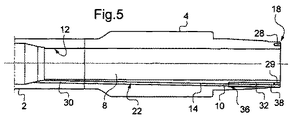
図5は、本発明の第一の実施の形態による第一の接合部4の詳細図である。 FIG. 5 is a detailed view of the first joint 4 according to the first embodiment of the present invention.
ドリルパイプ1の第一の末端面18は、中央孔8の長手方向軸に対して同軸上に延在する環状溝28を有し、上記第一の末端面18で開口している。
The
この環状溝28は、例えば、US6641434あるいはUS4605268に開示されている隣接するドリルパイプ間のデータ伝送において使用される、US6641454に開示されている環状コイルや、高い導電材料から成る環状層29を受けるためのものである。ここで、導電層の断面形状はU字型である。あるいは、環状溝28は、US6670880に開示されているのと同じ目的で、磁気導電/電気絶縁性(MCEI)U字谷部や、導電コイルを受けるためのものであってもよい。
This
第一ホール14は、中央孔8内で終端となるメイン部30と、第一の末端面18で終端となりメイン部30に隣接する末端部32とから構成される。末端部32は、第一ホール14に延在する追加孔とみなすことが出来る。
The
第一ホール14の長手方向軸は、環状溝28に対して傍心となる。第一ホール14の末端部32は、環状溝28と交わる。
The longitudinal axis of the
第一ホール14のメイン部30は、ガイドチューブ10の名目外径よりもわずかに大きな内径を有する。従って、ガイドチューブは、メイン部30内で自由に移動することができ、これにより、ガイドチューブ10は、第一ホール14内に用意に取り込まれる。
The
また、第一ホール14は、実質的に、ガイドチューブ10のその全長に渡る名目外径に対応した内径を有する。
The
第一ホール14の末端部32は、環状溝28の幅よりも低い直径を有する、あるいは、層29がある場合にはU字型導電層29の両壁間のギャップ幅よりも低い直径を有する。
The
また、第一ホール14の末端部32が、少なくとも末端部近くで、メイン部30の内径よりも大きな内径を有することにより、ショルダー面36が、第一ホール14のメイン部30と末端部32間の界面に形成される。
Further, since the
ガイドチューブ10における、末端部32に対応する部分、すなわちガイドチューブ10の末端部38は、ガイドチューブ10の名目直径よりも大きな外径を有する。ショルダー面36は、ガイドチューブ10の末端部38に対する当接面として機能する。ガイドチューブ10が、中央孔8へ長手方向に移動するのを防ぐ。
A portion of the
ここで、第一ホール14の末端部32は、長手方向の張力があらかじめガイドチューブにかけられるように、保有部として機能している。真っ直ぐに延在するガイドチューブにあらかじめ張力をかけておくことにより、ガイドチューブがドリルパイプの母線に沿って配置されて圧縮された場合に、ガイドチューブが歪んでしまうのを防ぐのに有効である。ガイドチューブが、ドリルパイプの中央部にある中央孔の表面に付着していないと、この歪みは特に弊害をもたらす。そして、ガイドチューブは、中央孔内で突き出てしまい、泥水の圧力低下を増加させ、ドリルストリングを降下させるツールにより損傷を受けてしまう。
Here, the
ここで、ガイドチューブ10の末端部38は、ガイドチューブの名目外径に対するガイドチューブ10の拡張部としてデザインされている。
Here, the
ガイドチューブ10は、名目外径のまま、第一の末端面18あるいは中央孔8から第一ホール14内に挿入される。その後、ガイドチューブ10の末端部38は、放射状に塑性的に拡張する。このような直径方向の拡張は、管用エキスパンダあるいはダジョニングによって形成され得る。
The
図6に示すように、末端部38を拡張し、更に、末端部38の外周部と第一ホール14の末端部32の内面部との間の接触圧力を維持するために、固定部37が、ガイドチューブ10の末端部38内に取り込まれる。例示された固定部37は、中空の筒状型である。
As shown in FIG. 6, in order to expand the
なお、ガイドチューブの使用は、内部を移動するツールにより容易に拡張され、特定位置で作動出来るという点において、特に有用である。 The use of the guide tube is particularly useful in that it can be easily expanded by a tool that moves inside and can be operated at a specific position.
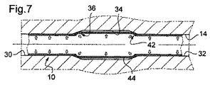
図7と図8は、本発明の第二の実施の形態を示している。 7 and 8 show a second embodiment of the present invention.
メイン部30と末端部32との間に、第一ホール14は、その長手方向に、メイン部30と末端部32の両方よりも大きな直径を有する中間部34を有している。
Between the
従って、第一ホール14は、メイン部30と中間部34との間の界面に(第一の)ショルダー面36を備え、中間部34と末端部32との間の界面にもう一つの(第二の)ショルダー面42を備える。
Accordingly, the
ここで、第一ホール14のメイン部30と末端部32は、実質的に同じ直径を有する。例えば、第一ホール14は、ある直径、すなわち名目直径を有し、この直径は、中間部34に沿った部分以外では、それ自身の長さ方向に渡ってほぼ一定の直径となる。
Here, the
第一ホール14の中間部34に対応して、ガイドチューブ10は、その名目外径よりも大きな外径を有する中間部44をその長手方向に備え、それにより、第一ホール14の第一のショルダー面36と第二のショルダー面42は、ガイドチューブ10の中間部44に対する当接面として機能する。そして、第一ホール14の中間部34は、ガイドチューブ10に対する保有部として機能する。
Corresponding to the
このような構成から、ガイドチューブが、長手両方向へ、すなわち、第一の末端面18と中央孔8へ移動するのを防ぐことが出来る。
From such a configuration, the guide tube can be prevented from moving in both longitudinal directions, that is, to the
この実施の形態では、ガイドチューブの長手方向に、あらかじめ張力あるいは圧縮力が保有部によりかけられていてもよい。 In this embodiment, tension or compressive force may be applied in advance in the longitudinal direction of the guide tube by the holding portion.
あらかじめ張力をかけることは、上記第一の実施の形態において述べられた理由により、ガイドチューブ10を真っ直ぐ保つのに有用である。
Pre-tensioning is useful for keeping the
あらかじめ圧縮力をかけることは、つる巻き形ガイドチューブ10にとって、ドリルパイプ1の長手方向中央部でガイドチューブ10を中央孔8の内面12に押し付けるのに、特に有用である。このようなガイドチューブ10の応力によって、中央孔8内の掘削泥水の圧力低下を最小化し、ドリルストリングを降下させるツールによる損傷を防ぐ。
It is particularly useful for the helically wound guide
また、第二のショルダー面42によって、ガイドチューブ10が、溝28内に収容されているカプラー装置方向へ移動するのを防ぐことが出来る。従って、このカプラー装置の損傷も防ぐことが出来る。
Further, the
中間(保有)部44は、図7に示すように、例えば、ダジョニング(dudgeonning)操作中に、塑性的に放射方向にガイドチューブ10を拡張させることで形成される。典型的には、この拡張が行われるのは、全長に渡る名目直径を有するガイドチューブ10が、第一ホール14内に挿入された後である。
As shown in FIG. 7, the intermediate (held)
第一ホール14の中間部44の内面34には、ねじ山付け、きざみ付け、そして/あるいはろう付けが行われる。これにより、第一ホール14内にガイドチューブ10を保持する特性が向上する。
The
図8は、ガイドチューブ10の中間部44を、拡張ツール45を使用して形成する例示的な拡張方法を示している。
FIG. 8 illustrates an exemplary expansion method in which the
拡張ツール45は、2つの金属部45Bと45Cとの間に配置された筒状エラストマー部45Aから構成される。筒状エラストマー部45Aは、金属部に作用する応力により、軸方向に収縮したり、放射状に拡張したりする。
The
この拡張ツール45がガイドチューブ10内に挿入されると、上記応力により、中間部44において、ガイドチューブ10が保有部34に向けて拡張する。
When the
ガイドチューブ10を保有部34に向けて拡張させるために、この拡張方法の代わりに、化学製品が使用されてもよい。
In order to expand the
保有部34は、必須ではないが、第一ホール14の終端部近くに配置される。
The holding
図9は、本発明の第三の実施の形態を示している。 FIG. 9 shows a third embodiment of the present invention.
第一ホール14は、自身のメイン部30よりも大きな直径を有する末端部32を備える。これにより、第一ホール14は、末端部32とメイン部30との間の界面に配置された第一のショルダー面36を備える。
The
ガイドチューブ10は、第一のショルダー面36に当接するように、名目外径よりも大きな外径を有する末端部38を有する。ガイドチューブの末端部38は、ガイドチューブ10の長手方向拡張部として形成される。
The
ガイドチューブ10に対する止め部材46が、第一ホール14の末端部32内に収容されている。ここで、この止め部材46は、ガイドチューブ10の終端面50に対する当接面48を形成している。
A
止め部材46は、第一ホール14の末端部32の内径に対応した外径を持つ中空筒状部としてデザインされている。
The
好ましくは、第一ホール14の末端部32は、ドリルパイプ1の末端面18で終端となる。この場合、止め部材46は、この末端面18から第一ホール14内に向かって挿入される。
Preferably, the
止め部材46は、少なくとも長手方向で、第一ホール14の末端部32に固定されている。
The
例えば、止め部材46は、自身の外周面と第一ホール14の末端部32の内面との間の摩擦継手手段により固定される。この摩擦継手は、例えば、ダジョニングのように、止め部材46を放射状に塑性的に拡張させて形成される。
For example, the
あるいは、止め部材46は、第一ホール14の末端部32の内面に接着されてもよい。
Alternatively, the
止め部材46の長さは、好ましくは、必要とされる継手強度に基づいて選択される。この継手長さは、ドリルパイプ1において予想される圧縮/屈曲/張力の強度によって判断される。
The length of the
本実施の形態では、第一ホール14の末端部32は、ガイドチューブ10に対する保有部として機能する。ガイドチューブ10が、長手両方向へ移動、すなわち、第一の末端面18や中央孔8へ移動するのを防ぐ。これによって、ガイドチューブ10の長手方向に、あらかじめ張力あるいは圧縮力をかけることが出来る。
In the present embodiment, the
この第三の実施の形態を特別に改良したものを、図10に示す。 FIG. 10 shows a special improvement of the third embodiment.
ここで、第一ホール14の末端部32は、保有部・終端環状溝28内で終端となる。
Here, the
止め部材46は、保有溝28内に形成された導電層29の固定要素としてデザインされている。
The
例えば、この止め部材46は、第一ホール14の末端部32の内径よりも大きな外径を有するフランジ部54あるいは襟部から構成され、止め部材46が導電層29の対応する開口部を通過すると、このフランジ部54は、導電層29を溝部28の底面31に押し付けることになる。
For example, the
同様のことが、U字型環状MCEI要素においても行われる。 The same is done for the U-shaped annular MCEI element.
止め部材46は、第一ホール14の末端部32の内面に対して拡張あるいは接着される。
The
図11は、本発明の第四の実施の形態を示す。 FIG. 11 shows a fourth embodiment of the present invention.
第一ホール14の末端部32は、メイン部30よりも小さな直径を備える。末端部32の直径は、ガイドチューブ10の名目外径よりも小さい。
The
従って、第一ホール14は、自身のメイン部30と末端部32との間の界面に位置するショルダー面36を有する。
Accordingly, the
ショルダー面36は、ガイドチューブ10の末端面50に対する当接面として機能する。
The
ガイドチューブ10は、上記末端部32の内径よりも大きな名目外径を備えているので、第一ホール14の末端部32には収容されない。ここで、ガイドチューブ10には、拡張部は必要とされない。
Since the
本実施の形態では、第一ホール14の末端部32は、ガイドチューブ部10の保有部として機能する。ガイドチューブ10が、長手方向に、ドリルパイプ1の第一の末端面18へ移動するのを防ぐ。これにより、ガイドチューブ10が移動して、溝部28内のカプラー装置、そして/あるいは、ガイドチューブ10に収容されているワイヤと上記カプラー装置との間の電気コネクタに損傷を与えることを防ぐ。更に、ガイドチューブ10の長手方向に、あらかじめ圧縮力をかけることを可能にする。
In the present embodiment, the
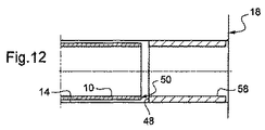
図12は、本発明の第五の実施の形態を示す。 FIG. 12 shows a fifth embodiment of the present invention.
第一ホール14は、自身の長さ方向に渡って、実質的に一定な直径を有する。すなわち、第一ホール14は、メイン部30と末端部32の両方を有していない。言い換えれば、メイン部30と末端部32は、同じ直径を有する。
The
止め部材46と同様の止め部材58をガイドチューブ10に対する当接面として作用させるために、止め部材は、第一ホール14内のガイドチューブ10の末端面50と末端面18との間あるいは溝部28との間に収容される。
In order for a
本実施の形態では、ガイドチューブ10が、長手方向に、ドリルパイプ1の第一の末端面18へ移動するのを防ぐ。更に、ガイドチューブ10の長手方向に、あらかじめ圧縮力をかけることが可能になる。
In the present embodiment, the
止め部材58は、第一ホール14の内面に対して拡張あるいは接着される。あるいは、摩擦継手が、止め部材58と第一ホール14の内面との間に備えられてもよい。
The
図13は、本発明の第六の実施の形態を示す。 FIG. 13 shows a sixth embodiment of the present invention.
第一ホール14は、その長手方向に、中間部34を介して接合されたメイン部30と末端部32を有する。
The
第一ホール14の末端部32は、少なくともこの末端部32近くにおいて、メイン部30よりも大きな直径を備えている。メイン部30は、必須ではないが、自身の全長に渡って同じ内径を有している。
The
第一ホール14の中間部34は、末端部32をメイン部30に接続するテーパー部のようにデザインされている。ガイドチューブ10は、自身の名目直径よりも大きな直径を有する末端部と、末端部38をガイドチューブ10の残りの部分に接続して第一ホール14の中間部34に対応させた中間部と、を備える。ガイドチューブ10の中間部は、放射状に塑性的に拡張している。
The
ガイドチューブ10の保持能力を向上するために、特に、きつく引っ張った状態で、テーパーV字部61が、ガイドチューブ10内の中間部に配置されている。
In order to improve the holding capacity of the
中間部34は任意なものである。
The
テーパーV字部61は、摩擦溶接を起こすように、比較的高い回転速度で挿入されてもよい。
The tapered V-shaped
テーパーV字部61の使用により、ガイドチューブ10と第一ホール14との間に、金属封止部を形成する。
By using the tapered V-shaped
ガイドチューブ10に対する保持、あらかじめの応力負荷、そして/あるいは封止を補強するために、テーパーV字部61の数は、末端部38の異なる直径を有する様々な長手部分の数に対応させる。
In order to reinforce retention, prestressing and / or sealing against the
図14は、本発明の第七の実施の形態を示す。 FIG. 14 shows a seventh embodiment of the present invention.
第一ホール14は、長手方向に、自身の末端部32を自身のメイン部30に接合する中間部34を有する。ここで、末端部32の内径と、中間部34に近いメイン部30の内径は同じであり、すなわち、中間部34の名目直径となる。
The
この中間部34は、長手方向に、中間部34の残りの部分、すなわち、中間部34の名目直径よりも大きな内径を有する多数の保有部63を有する。
The
ここで、中間部34の名目直径と、第一ホール14の名目直径は同じとなる。
Here, the nominal diameter of the
保有部63は、例えば、ターニング、スロッティング、あるいはミリングによって、中央孔8の内面12を放射状に加工した溝のようにデザインされている。
The holding
ガイドチューブ10は、長手方向に、自身の第一の末端部38を自身のメイン部に接続する中間部を備えている。ガイドチューブ10の中間部は、第一ホール14の中間部34に対応している。ガイドチューブ10の中間部は、第一ホール14の保有部63に対応する、放射状に塑性的に拡張する部分を有する。
The
選択的には、ガイドチューブ10を保護し、第一ホール14内のガイドチューブ10に対する保有、あらかじめの応力負荷、そして/あるいは封止性を向上させるために、第一ホール14の保有部63を形成する溝部には、溶融金属物質あるいは合成物質が満たされている。
Optionally, in order to protect the
図15は、本発明の第八の実施の形態を示す。 FIG. 15 shows an eighth embodiment of the present invention.
第一ホール14の中間部34は、ドリルパイプ1の中央孔8で開口し、この中央孔8の内面12に形成されたポケット65を備える。ここで、ポケット65は、平行管形状を有しているが、例えば、筒状にデザインされた他の形状でもよい。
The
第一ホール14の中間部34に対応するガイドチューブ10の中間部は、放射状に塑性的に拡張する拡張部75を備える。これにより、ガイドチューブ10に対する第一の当接面71が、ポケット65の一方の長手終端部に配置され、ガイドチューブ10に対する第二の当接面72が、ポケット65のもう一方の長手終端部に配置される。
The intermediate portion of the
言い換えれば、ポケット65は、ガイドチューブ10の保有部として作用し、このガイドチューブ10が、長手両方向に移動するのを防ぐ。更に、ガイドチューブ10に、あらかじめ張力あるいは圧縮力をかけることが可能となる。
In other words, the
選択的には、付属保有部67を使用して、ガイドチューブ10に対する保有特性、そして/あるいは、あらかじめの応力負荷特性を向上させる。
Optionally, the attached holding
例示的な付属保有部67は、2つの環状リング69から構成される。環状リング69は、第一の当接面71と第二の当接面72のうちの片方と、それぞれ当接する。
The
ガイドチューブ10は、環状リング69の片方ずつを通過する。環状リング69は、ガイドチューブ10に対する環状シート面73を、それぞれ備える。
The
各環状シート面73は、ガイドチューブの拡張部75とそれ以外の部分との間のガイドチューブ10の移行部に連動するテーパー部としてデザインされている。
Each
保有要素67が、この環状リング69同士を接合する外側袖部77から構成されてもよい。
The holding
選択的には、この外側袖部77とガイドチューブ10の間の空間には、封止のために溶融金属あるいは合成物質がみたされている。
Optionally, molten metal or synthetic material is seen in the space between the
図16は、本発明の第九の実施の形態を示す。 FIG. 16 shows a ninth embodiment of the present invention.
第八の実施の形態で示したように、第一ホール14の中間部34は、中央孔8の内面12に配置されたポケット65から構成される。
As shown in the eighth embodiment, the
ここで、ガイドチューブ10の第一の末端部38は、ポケット65近くで、第一ホール14のメイン部30内に収容されている。
Here, the
機械的保有部79が、ガイドチューブ10を、例えばきつく引っ張った状態で維持するようにポケット65内に配置されている。
A
機械的保有部79として、ねじ/留めねじシステムが例示される。上記ねじ/留めねじシステムの留めねじは、第一の当接面71と、第一ホール14のメイン部30に近い方の第二の当接面72のうちの一方に適用される。上記ねじ/留めねじシステムのねじは、ガイドチューブ10に対して引っ張り応力を負荷する。
An example of the mechanical holding
あるいは、機械的保有要素79は、伸筋のようにデザインされてもよい。
Alternatively, the
選択的には、ポケット65は、袖部によって保護されている。
Optionally, the
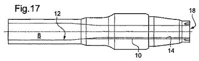
図17は、本発明の第十の実施の形態を示す。 FIG. 17 shows a tenth embodiment of the present invention.
ここで、少なくとも第一ホール14の一部分は、中央孔8の内面12に配置される溝としてデザインされている。
Here, at least a part of the
ガイドチューブ10は、上記溝内に収容され、例えば溶接により、その内面に固定される。
The
ガイドチューブは、長手方向に、あらかじめ張力あるいは圧縮力がかけられた状態で固定される。 The guide tube is fixed in the longitudinal direction in a state where a tension or a compressive force is applied in advance.
溝部は、メインパイプ2の第一の末端面18で終端となる。
The groove ends at the
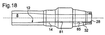
図18は、本発明の第十一の実施の形態を示す。 FIG. 18 shows an eleventh embodiment of the present invention.
第一ホール14のメイン部は、中央孔8の内面12に、典型的には長手方向に、配置された溝部81としてデザインされている。
The main part of the
第一ホール14は、長手方向に、自身のメイン部を末端部32に接合する中間部を備える。第一ホール14の中間部は、中央孔8の内面12に配置されたポケット85としてデザインされている。
The
ここで、第一ホール14の末端部32は、終端溝部28内で終端している。
Here, the
ガイドチューブ10のメイン部は、長手方向に溝堀されたメイン部81内に収容されており、少なくともその内面の一部分で、例えば溶接により固定されている。ガイドチューブ10は、あらかじめ張力あるいは圧縮力がかけられた状態で保有される。ポケット85は、袖部により保護される。
The main portion of the
溝領域は、例えばミリングすることにより平らに、あるいは、例えばターニングで加工することにより円形に形成される。第一ホール14の末端部32は、例えば一対の溝28から作業を行い、ガンドリルのように奥方向に削ることによって、加工される。
The groove region is formed flat, for example, by milling, or circular, for example, by machining with turning. The
別の実施の形態として、第一ホール14の溝部81とこの第一ホール14の末端部32との間にポケットを配置していない。
As another embodiment, no pocket is arranged between the
更に、ガイドチューブ10は、例えば、スエージ加工あるいは溶接加工により、第一ホール14の末端部32内部に保持される。
Furthermore, the
溝部が、中央孔8に対して同心円状である場合、溝部81は、バックボーリング加工により加工される。
When the groove is concentric with respect to the
図19は、本発明の第十二の実施の形態を示す。 FIG. 19 shows a twelfth embodiment of the present invention.
ガイドチューブ10の第一の末端部38は、第一ホール14の末端部32で保持される。
The
ガイドチューブ10の第一の末端部38は、ガイドチューブ10に対して当接面を形成するフランジ部91から構成される。フランジ部91は、ガイドチューブ10が、第二の接合部6に向かう長手方向に移動するのを防ぐ。ガイドチューブ10は、長手方向にあらかじめ応力(張力)がかけられた状態で保有されていてもよい。
The
フランジ部91は、ドリルパイプの第一の末端面18上に溶接することにより、更に、ガイドチューブの長手方向に、あらかじめ圧縮力をかけることが出来る。本実施の形態では、好ましくはステンレス鋼が使用される。
The flange portion 91 can be preliminarily applied with a compressive force in the longitudinal direction of the guide tube by welding on the
選択的には、溶接能力を上げるために、例えば、ガイドチューブ10内部にくさびを挿入するなど、機械的な構成要素が使用される。
Optionally, mechanical components are used to increase the welding capability, such as inserting a wedge inside the
上記実施の形態によれば、ガイドチューブ10が、ドリルパイプ1の中央孔8へ、そして/あるいは、ドリルパイプ1の第一の末端面18あるいは第二の末端面20へ、長手方向に移動するのを防ぐ。これにより、ガイドチューブ10に、長手方向の圧縮力と/あるいは張力といった応力がかけられる。言い換えると、ドリルパイプ1に作用する張力、圧縮力、そして/あるいは湾曲負荷により、ガイドチューブ10に圧縮力と/あるいは張力といった応力がかけられる。
According to the above embodiment, the
保有部材により、少なくともメインチューブにかかる応力のいくらかは、ガイドチューブ10に対応する応力を発生させ、その応力は、保有部材の適切なデザインにより反発されている。
The holding member causes at least some of the stress on the main tube to generate a stress corresponding to the
ここまで述べてきた実施の形態のほとんどに関連するように、ガイドチューブ10を第一の接合部4と第二の接合部6に対して封止した場合、ガイドチューブ10の外面に、特に、第一ホール14と第二ホール16のうちのガイドチューブが収容されていない方に、更に、泥水の圧力が負荷される。
As related to most of the embodiments described so far, when the
ガイドチューブ10を第一の接合部4と第二の接合部6に対して封止しない場合、ガイドチューブ10の外面と内面両方に、おおまかには同じ圧力がかかる。この場合、ガイドチューブ10には泥水の圧力が負荷されない。
When the
図22は、異なった低圧力がガイドチューブ10に負荷された時の、ガイドチューブ10に生じる応力を示す。張力と圧縮力負荷が横軸に置かれ(張力は正の値)、上記異なった応力が縦軸に置かれている(内部圧力は正の値)。ガイドチューブ10のイールド(塑性変形)の限界曲線も、図22に示す。この限界曲線は、フォンミーゼス等価応力理論により楕円形を成す。
FIG. 22 shows the stress generated in the
図23は、異なった高圧力負荷の図22の類似形態を示す。 FIG. 23 shows an analogy of FIG. 22 with different high pressure loads.
両者とも、ガイドチューブには、ドリルパイプに使用荷重や泥水の圧力が負荷される前の、あらかじめ長手方向に張力がかけられた状態である。 In both cases, tension is applied to the guide tube in the longitudinal direction in advance before the working load or muddy water pressure is applied to the drill pipe.
図22では、応力の代表点が横軸上に位置しており、ガイドチューブ全体で応力に差はない。これら応力の代表点は、フォンミーゼスの楕円形内側に存在している。 In FIG. 22, the representative point of stress is located on the horizontal axis, and there is no difference in stress in the entire guide tube. The representative points of these stresses exist inside the von Mises ellipse.
図23では、応力の代表点がフォンミーゼスの楕円形外側に位置している。すなわち、ガイドチューブ10が破壊されるリスクがある。
In FIG. 23, the representative point of stress is located outside the von Mises ellipse. That is, there is a risk that the
圧力差が大きい場合には、例えば、低炭素鋼(235MPAの降伏応力を有する)やインコネル825(1000MPAの降伏応力を有する)を使用して、ガイドチューブ10の材料を性能向上させることが必要である。
When the pressure difference is large, it is necessary to improve the performance of the material of the
図20は、本発明の第十三の実施の形態を示す。 FIG. 20 shows a thirteenth embodiment of the present invention.
上記実施の形態のうちのひとつによれば、ガイドチューブ10は、好ましくは、パイプの両側に保持される。これにより、ガイドチューブ10が長手両方向へ移動するのを防ぐ。好ましくは、ガイドチューブ10が矢印95で示された張力を維持している状態である。
According to one of the above embodiments, the
ガイドチューブ10は、データ伝送ワイヤ収納用の付属ガイドチューブ93を収容している。
The
付属ガイドチューブ93は、両端に保持も保有もされていない。これにより、付属ガイドチューブが、第一の接合終端部4と第二の接合終端部6に保持されているガイドチューブ10内部で、長手両方向へ自由に移動することが出来る。
The attached
ここで、ガイドチューブ10は、封止ではなく、ここまで開示されてきた手段のいずれかにより、維持あるいは保有され、これにより、図20の太線矢印で示された泥水の圧力が、付属ガイドチューブ93に作用する。
Here, the
付属ガイドチューブ93は、封止システム94の使用により、泥水漏れのないように配置されている。封止システム94は、エラストマー材料の弾力性のある封止リングであってもよい。
The attached
これにより、圧力と湾曲の影響が組み合わさって主にガイドチューブ10に湾曲応力が作用することは生じず、これに対して、付属ガイドチューブ93に泥水の圧力が作用する。
As a result, the influence of the pressure and the bending is not combined and the bending stress does not mainly act on the
これにより、ドリルパイプ1を用意にデザインすることが出来る。ガイドチューブ10が軸方向応力(張力や圧縮力)に耐え得るように、ガイドチューブ10の寸法と材料が選択され、これに対し、付属ガイドチューブ93では、泥水の圧力による破壊に耐え得るようにのみ、付属ガイドチューブ93の寸法と材料が選択される。言い換えると、ガイドチューブ10と付属ガイドチューブ93は、個別に最適化が行われる。
Thereby, the
選択的には、ガイドチューブ10はホールを備え、ガイドチューブ10の外面と内面の間の圧力差を低く保たせる。
Optionally, the
図20の実施の形態の変形例として、付属ガイドチューブ93と内包されているワイヤは、特有の装甲同軸ケーブルとして形成される。
As a modification of the embodiment of FIG. 20, the attached
図21は、更に別の実施の形態を示す。 FIG. 21 shows still another embodiment.
ここで、ガイドチューブ10は、データ伝送ワイヤを収容しており、上記実施の形態のうちのいずれかの手段により、矢印98で示したように、ドリルパイプ1の両端に維持あるいは保有される。
Here, the
ガイドチューブ10は、ドリルパイプ1に対して長手両方向に自由に移動する付属鞘96内に収容されている。付属鞘96には、外的(泥水の)圧力が負荷されるが、封止システム97により、この圧力に抵抗している。これにより、ガイドチューブ10にはこの外的圧力がかからない。
The
別の実施の形態においても、長手方向負荷と泥水の圧力の組み合わせを、ワイヤ保護システムに生じないような効果が可能となる。 In other embodiments, the combination of longitudinal load and muddy water pressure can be achieved without causing the wire protection system.
上記実施の形態では、第一ホール14に保有手段を設けて、ガイドチューブ10が片方あるいは両方の長手方向に移動するのを防ぐ。
In the above embodiment, the holding means is provided in the
同様に、第二ホール16は、上記で開示した保有手段のいずれかを有してもよい。好ましくは、第一の接合部4と第二の接合部6に対して同様の形成作業が行えるので、第一ホール14と第二ホール16の両者は、同じ保有手段を備える。
Similarly, the
極めて特異的な応用例としては、第二ホール16が、全く保有手段を有しないことである。
A very specific application is that the
ドリルパイプが湾曲されたり、軸方向に圧縮される、あるいは引き伸ばされたりする時に重要となる、ガイドチューブ10の長手方向への移動が防がれる。
The movement of the
(一般的には、中央孔に沿って真っ直ぐに延在している)ガイドチューブ10が、中央孔の内面に接着されていたり、コーティング層に埋め込まれていたりするようなドリルパイプでは、本発明により、接着手段の適用あるいはコーティング層を形成させる前に、ガイドチューブに張力を保有させる(あらかじめかける)ことができ、これにより、メインチューブ内面に対してガイドチューブを引き伸ばすことが出来る。従って、メインパイプ2に負荷するすべての荷重、特に圧縮力と/あるいは張力によって、ガイドチューブ10に対応する応力を負荷させて、この応力強度は、保有手段のデザイン重要性を低くするような(メインチューブ内面に接着されない)フリー(自由移動)ガイドチューブを使用した場合よりも低くなる。
In a drill pipe in which the guide tube 10 (generally extending straight along the central hole) is adhered to the inner surface of the central hole or embedded in the coating layer, the present invention is used. Thus, before applying the adhesive means or forming the coating layer, the guide tube can be tensioned (applied in advance), whereby the guide tube can be stretched against the inner surface of the main tube. Accordingly, the stress corresponding to the
また、本発明では、溝部28内部の導電層やカプラー装置といったその他手段、あるいはその他導電要素が、ドリルパイプにかかる圧縮力により、ガイドチューブ10の終端部を介して損傷するのも防ぐ。
Further, according to the present invention, other means such as a conductive layer and a coupler device in the
ガイドチューブが中央孔に沿って真っ直ぐに延在し、中央孔8の内面に接着されていないドリルパイプでは、ガイドチューブの圧縮と/あるいは湾曲による中央孔でのガイドチューブ10の突き抜け、そして/あるいは、導電層29の損傷を防ぐために、ガイドチューブ10には、あらかじめ応力(張力)が負荷される。本発明を適用することにより、上記のようにあらかじめ応力を負荷されたガイドチューブ10が提供される。
For drill pipes in which the guide tube extends straight along the central hole and is not bonded to the inner surface of the
ガイドチューブがつる巻き状に延在する場合、ガイドチューブをメインパイプ2の中央孔8に押し付けるには、圧縮力をあらかじめ負荷することが適している。
When the guide tube extends in a spiral shape, it is suitable to preload the compression tube in order to press the guide tube against the
上記いくつかの実施の形態では、特に、摩擦継手を使用すると、保有手段により、第一ホール内のガイドチューブが固定されている。このような固定は、本発明のいくつかの利点を得るのに必要ではないということは理解されるであろう。 In some of the above embodiments, particularly when a friction joint is used, the guide tube in the first hole is fixed by the holding means. It will be appreciated that such fixation is not necessary to obtain some of the advantages of the present invention.
本発明は、限られた数の実施の形態によって述べられている。しかしながら、この開示による利益を享受する当業者は、その他の実施の形態を本発明の範囲から逸脱しないように考案出来ることを、十分に理解されるであろう。例えば、以下のようである。 The invention has been described with a limited number of embodiments. However, one of ordinary skill in the art having the benefit of this disclosure will appreciate that other embodiments can be devised without departing from the scope of the present invention. For example:
ガイドチューブの終端部は、第一/第二ホール内の長手方向のどの位置においても配置され得る。 The end of the guide tube can be located at any longitudinal position within the first / second hole.
第一/第二ホールに関して、例えば、仏国特許出願FR08/05376で見られるように、一般的に(ホールは、中央孔軸に並行ではないように延在する)あるいは明確に(ホールは、中央孔8から環状溝部28まで多数の調節部分を有する)これまで述べられてきたよりも、第一/第二ホールは更に複雑なパターンを有し得る。
With respect to the first / second hole, for example, as seen in French patent application FR08 / 05376, generally (the hole extends not parallel to the central hole axis) or clearly (the hole is The first / second hole may have a more complex pattern than has been described so far (with multiple adjustment portions from the
第一/第二ホールは、環状溝部28以外の場所で終端となってもよく、仏国特許出願FR08/05376で見られるように、選択的に考慮され得る。
The first / second holes may terminate at locations other than the
ガイドチューブは、中央孔8の後に異なるパターンが続いて延在することが出来る。
The guide tube can extend after the
保護層は、中央孔8の内面上のガイドチューブに適応される。あるいは、溶接や接着結合のような異なった接着手段も使用され得る。
The protective layer is adapted to the guide tube on the inner surface of the
第一ホール14と第二ホール16、対応するガイドチューブ10の第一の終端部22とガイドチューブ10の第二の終端部24は、上記のような異なる実施の形態に基づいて配置される。
The
本発明は、ドリルパイプに限定されず、重量ドリルパイプ、ドリルカラー、あるいはその他のいかなるドリルストリング構成要素にも適応され得る。
The invention is not limited to drill pipes, but can be applied to heavy drill pipes, drill collars, or any other drill string component.
第一ホール14の末端部32は、環状溝28の幅よりも大きな直径を有する、あるいは、層29がある場合にはU字型導電層29の両壁間のギャップ幅よりも大きな直径を有する。
The
Claims (25)
上記保護手段は、メインパイプ(2)の中央孔(8)内部に延在し、
メインパイプ(2)は、上記接合終端部のうちの片方(4)において第一ホール(14)と、もう一方の接合終端部(6)において第二ホール(16)を備え、
両ホールは、中央孔(8)で繋がっている特徴を有するドリルストリングであって、
保護手段は、上記ワイヤを収容するように配置されたガイドチューブ(10)を備え、
ガイドチューブ(10)の両終端部は第一ホール(14)と第二ホール(16)内部にそれぞれ配置され、
保有手段が、ガイドチューブ10の各終端部において、少なくとも第一ホール(14)と第二ホール(16)のうちの一方に配置され、
上記保有手段は、上記第一ホール(14)と第二ホール(16)のうちの一方に対して、上記ガイドチューブ10の各終端部が、少なくとも上記ホールの長手方向に移動するのを防ぐようにデザインされている。 The drill string element (1) comprises a main pipe (2) having a junction termination (4, 6) and a protection means for at least one wire;
The protective means extends inside the central hole (8) of the main pipe (2),
The main pipe (2) is provided with a first hole (14) in one (4) of the junction terminations and a second hole (16) in the other junction termination (6).
Both holes are drill strings having the characteristics of being connected by a central hole (8),
The protective means comprises a guide tube (10) arranged to accommodate the wire,
Both end portions of the guide tube (10) are disposed inside the first hole (14) and the second hole (16), respectively.
A holding means is disposed in at least one of the first hole (14) and the second hole (16) at each end portion of the guide tube 10,
The holding means prevents each terminal portion of the guide tube 10 from moving at least in the longitudinal direction of the hole with respect to one of the first hole (14) and the second hole (16). It is designed.
上記保有手段は、ガイドチューブ(10)が、上記ホール(14、16)の長手両方向に移動するのを防ぐように配置される。 The drill string element according to claim 1, wherein
The holding means is arranged to prevent the guide tube (10) from moving in both longitudinal directions of the holes (14, 16).
上記保有手段は、ガイドチューブ(10)に対する少なくともひとつの当接面(36、42、48)を備え、上記当接面は、上記ホール(14、16)において放射状に延在している。 A drill string element according to any one of claims 1-2,
The holding means comprises at least one abutment surface (36, 42, 48) for the guide tube (10), and the abutment surface extends radially in the holes (14, 16).
上記当接面(36、42、48)は、ガイドチューブ(10)の放射状終端面(50)と連動する。 A drill string element according to claim 3,
The abutment surfaces (36, 42, 48) are interlocked with the radial end surface (50) of the guide tube (10).
上記少なくともひとつの当接面(36、42、48)は、ガイドチューブ(10)の放射状拡大部(44)と連動する。 A drill string element according to any one of claims 3-4,
The at least one abutment surface (36, 42, 48) is interlocked with the radially enlarged portion (44) of the guide tube (10).
上記少なくともひとつの当接面(36、42)は、上記ホール(14、16)のショルダー面として配置される。 A drill string element according to any one of claims 3-5,
The at least one abutment surface (36, 42) is arranged as a shoulder surface of the hole (14, 16).
上記少なくともひとつの当接面(48)は、上記ホール(14、16)内部に位置する付属部材(46、58)の終端面として配置され、上記付属部材が相対的に上記ホール(14、16)の長手方向どちらにも移動するのを防ぐように固定手段が上記ホール(14、16)に備えられる。 A drill string element according to any one of claims 3-5,
The at least one abutment surface (48) is disposed as an end surface of an attachment member (46, 58) located inside the hole (14, 16), and the attachment member is relatively positioned relative to the hole (14, 16). ) Is provided in the holes (14, 16) so as to prevent movement in either of the longitudinal directions.
上記付属部材(46、58)に対する固定手段は、付属部材の外面と上記ホール(14、16)の内面との間に、摩擦継手を備える。 A drill string element according to claim 7,
The fixing means for the attachment member (46, 58) includes a friction joint between the outer surface of the attachment member and the inner surface of the hole (14, 16).
上記摩擦継手は、上記付属部材(46、58)の直径方向への拡大から派生している。 A drill string element according to claim 8,
The friction joint is derived from the diametrical expansion of the attachment members (46, 58).
上記ホール(14、16)は、環状溝部(28)の底面(31)で終端となり、この環状溝部は、信号を別のドリルストリング要素に伝送するためのカプラー装置の対応する環状要素(29)を受け、
付属部材は、上記環状要素の開口部を通過する対応する環状要素(29)の固定要素として配置される。 A drill string element according to any one of claims 7-9,
The holes (14, 16) terminate at the bottom surface (31) of the annular groove (28), which corresponds to the corresponding annular element (29) of the coupler device for transmitting the signal to another drill string element. Receive
The attachment member is arranged as a fixing element of the corresponding annular element (29) that passes through the opening of the annular element.
上記少なくともひとつの当接面(73)は、ガイドチューブ(10)が通過する付属部材(69)の内面としてデザインされる。 A drill string element according to any one of claims 3-5,
The at least one abutment surface (73) is designed as the inner surface of the attachment member (69) through which the guide tube (10) passes.
付属部材(69)は、中央孔(8)上の開口部となる内部くぼみ(65)内に位置し、上記ホール(14、16)は、内部くぼみ内を通過、あるいは内部くぼみで終端となる。 A drill string element according to claim 11, comprising:
The attachment member (69) is located in an internal recess (65) that becomes an opening on the central hole (8), and the holes (14, 16) pass through the internal recess or terminate at the internal recess. .
保有手段は、上記ホール(14、16)のメイン部(32)よりも大きな断面直径を有する該ホールの長手部分において、上記ホール(14、16)の少なくともひとつの保有部(34)を備える。 A drill string element according to any one of the preceding claims,
The holding means includes at least one holding portion (34) of the hole (14, 16) in a longitudinal portion of the hole having a larger cross-sectional diameter than the main portion (32) of the hole (14, 16).
上記保有部(34)は、ガイドチューブ(10)の放射状拡大部(44)と連動する。 A drill string element according to claim 13,
The said holding | maintenance part (34) interlock | cooperates with the radial expansion part (44) of a guide tube (10).
上記保有部(34)は、中央孔(8)上の開口部となる少なくともひとつのくぼみ(63)を備え、この奥行きは、ホール(14、16)のメイン部(32)の直径よりも大きい。 A drill string element according to any one of claims 13-14,
The holding part (34) includes at least one indentation (63) which becomes an opening on the central hole (8), and this depth is larger than the diameter of the main part (32) of the holes (14, 16). .
上記少なくともひとつのくぼみは、金属材料あるいは合成材料で満たされている。 The drill string element according to claim 15,
The at least one indentation is filled with a metallic material or a synthetic material.
ガイドチューブ(10)に対する固定部材(79)は、くぼみ(65)内部に配置される。 A drill string element according to any one of claims 12-16,
A fixing member (79) for the guide tube (10) is arranged inside the recess (65).
上記固定手段は、ガイドチューブ(10)の長手方向終端部の片方と連動するねじ/留めねじ保有部を備える。 A drill string element according to claim 17,
The fixing means includes a screw / fastening screw holding portion that interlocks with one of the longitudinal end portions of the guide tube (10).
上記保有手段は、上記ホール(14、16)の長手部分の内面と、ガイドチューブ(10)の長手部分の外面との間に配置された摩擦継手を備える。 A drill string element according to any one of the preceding claims,
The holding means includes a friction joint disposed between the inner surface of the longitudinal portion of the hole (14, 16) and the outer surface of the longitudinal portion of the guide tube (10).
上記ホール(14、16)は、中央孔(8)の内面(12)上に開口する長手方向溝部(81)として形成された長手部分を備える。 A drill string element according to any one of the preceding claims,
The holes (14, 16) comprise a longitudinal portion formed as a longitudinal groove (81) opening on the inner surface (12) of the central hole (8).
上記ホール(14、16)は、対応する接合終端部の末端面で終端となり、ガイドチューブ(10)は、上記末端面で当接するフランジ部(91)としてデザインされた長手方向末端部を備える。 A drill string element according to any one of the preceding claims,
The holes (14, 16) terminate at the end face of the corresponding joining end, and the guide tube (10) comprises a longitudinal end designed as a flange part (91) abutting at the end face.
上記保有手段は、ガイドチューブと、対応する接合終端部との間に、封止部を形成する。 A drill string element according to any one of the preceding claims,
The holding means forms a sealing portion between the guide tube and the corresponding joining terminal portion.
ガイドチューブ(10)は、上記少なくとも1本のワイヤを収容する付属ガイドチューブ(93)を収容して、ガイドチューブの外周面と内周面との間で泥水をやり取りする手段を備え、
付属ガイドチューブ(93)は、ガイドチューブ(10)に対して、長手方向に自由に移動することが出来るように配置される。 A drill string element according to any one of the preceding claims,
The guide tube (10) includes an accessory guide tube (93) that stores the at least one wire, and includes means for exchanging muddy water between the outer peripheral surface and the inner peripheral surface of the guide tube,
The attached guide tube (93) is arranged so as to be freely movable in the longitudinal direction with respect to the guide tube (10).
ガイドチューブ(10)は、接合終端部を封止するような筒状鞘部に収容され、上記接合終端部に対して、自由に移動することが出来るように配置される。 A drill string element according to any one of the preceding claims,
The guide tube (10) is accommodated in a cylindrical sheath portion that seals the joining end portion, and is arranged so as to be freely movable with respect to the joining end portion.
ガイドチューブは、その長手方向に張力あるいは圧縮力が負荷されるように、あらかじめ応力が負荷された状態で保持される。 A drill string element according to any one of the preceding claims,
The guide tube is held in a state in which stress is applied in advance so that tension or compressive force is applied in the longitudinal direction.
Applications Claiming Priority (3)
| Application Number | Priority Date | Filing Date | Title |
|---|---|---|---|
| EP09290230.3 | 2009-03-30 | ||
| EP09290230.3A EP2236736B8 (en) | 2009-03-30 | 2009-03-30 | Wired drill pipe |
| PCT/EP2010/001338 WO2010115492A2 (en) | 2009-03-30 | 2010-03-04 | Wired drill pipe with improved configuration |
Publications (1)
| Publication Number | Publication Date |
|---|---|
| JP2012522194A true JP2012522194A (en) | 2012-09-20 |
Family
ID=40937451
Family Applications (1)
| Application Number | Title | Priority Date | Filing Date |
|---|---|---|---|
| JP2012502479A Pending JP2012522194A (en) | 2009-03-30 | 2010-03-04 | Wired drill pipe with improved structure |
Country Status (11)
| Country | Link |
|---|---|
| US (1) | US9200486B2 (en) |
| EP (1) | EP2236736B8 (en) |
| JP (1) | JP2012522194A (en) |
| CN (1) | CN102395746A (en) |
| AR (1) | AR075986A1 (en) |
| BR (1) | BRPI1012640B1 (en) |
| CA (1) | CA2757150A1 (en) |
| MX (1) | MX2011010256A (en) |
| NO (1) | NO2236736T3 (en) |
| RU (1) | RU2011143417A (en) |
| WO (1) | WO2010115492A2 (en) |
Families Citing this family (29)
| Publication number | Priority date | Publication date | Assignee | Title |
|---|---|---|---|---|
| AT508272B1 (en) * | 2009-06-08 | 2011-01-15 | Advanced Drilling Solutions Gmbh | DEVICE FOR CONNECTING ELECTRICAL WIRES |
| FR2965415B1 (en) | 2010-09-24 | 2012-09-07 | Electronique Ind De L Ouest Tronico | COUPLER FOR COUPLING A FIRST AND A SECOND SECTION OF A TRANSMISSION LINE, CORRESPONDING DATA TRANSMISSION SYSTEM AND CORRESPONDING COMPONENT |
| FR2965602B1 (en) | 2010-10-04 | 2013-08-16 | Electronique Ind De L Ouest Tronico | TUBE FOR TRANSPORTING SUBSTANCES AND ASSEMBLING TUBES THEREFOR |
| EP2657418B1 (en) * | 2012-04-26 | 2015-01-14 | Airbus Operations GmbH | Noise reduction unit for vacuum suction drains |
| US9322223B2 (en) * | 2012-05-09 | 2016-04-26 | Rei, Inc. | Method and system for data-transfer via a drill pipe |
| CN103485767A (en) * | 2012-06-14 | 2014-01-01 | 中国石油天然气集团公司 | Cabled transmission device for connecting threaded joint |
| CN103573257A (en) * | 2012-07-20 | 2014-02-12 | 中国石油天然气集团公司 | Information transmission device for well logging during drilling |
| US8944697B2 (en) | 2012-09-28 | 2015-02-03 | Positronic Industries, Inc. | Fiber optic connector assembly |
| GB2527430B (en) * | 2012-12-21 | 2018-05-02 | Baker Hughes Inc | Electronic frame for use with coupled conduit segments |
| US9810806B2 (en) | 2012-12-21 | 2017-11-07 | Baker Hughes Incorporated | Electronic frame for use with coupled conduit segments |
| US9422802B2 (en) * | 2013-03-14 | 2016-08-23 | Merlin Technology, Inc. | Advanced drill string inground isolator housing in an MWD system and associated method |
| US9598951B2 (en) | 2013-05-08 | 2017-03-21 | Baker Hughes Incorporated | Coupled electronic and power supply frames for use with borehole conduit connections |
| NO20130951A1 (en) | 2013-07-09 | 2013-07-09 | Modi Vivendi As | Systems for optimized, intelligent and autonomous drilling operations |
| US9850718B2 (en) | 2013-08-07 | 2017-12-26 | Baker Hughes, A Ge Company Llc | Retention device for drill pipe transmission line |
| US9644433B2 (en) | 2013-08-28 | 2017-05-09 | Baker Hughes Incorporated | Electronic frame having conductive and bypass paths for electrical inputs for use with coupled conduit segments |
| US9512682B2 (en) | 2013-11-22 | 2016-12-06 | Baker Hughes Incorporated | Wired pipe and method of manufacturing wired pipe |
| US9611702B2 (en) * | 2014-01-23 | 2017-04-04 | Baker Hughes Incorporated | Wired pipe erosion reduction |
| US9768546B2 (en) * | 2015-06-11 | 2017-09-19 | Baker Hughes Incorporated | Wired pipe coupler connector |
| WO2018052428A1 (en) | 2016-09-15 | 2018-03-22 | Halliburton Energy Services, Inc. | Downhole wire routing |
| USD873392S1 (en) * | 2017-08-31 | 2020-01-21 | Rotary Connections International Ltd. | Drill pipe |
| US10975630B1 (en) | 2020-02-06 | 2021-04-13 | Saudi Arabian Oil Company | Expansion tubing joint with extendable cable |
| US11274549B2 (en) * | 2020-03-18 | 2022-03-15 | Saudi Arabian Oil Company | Logging operations in oil and gas applications |
| US11286725B2 (en) | 2020-03-18 | 2022-03-29 | Saudi Arabian Oil Company | Drill pipe segments for logging operations |
| US11598157B2 (en) | 2021-03-11 | 2023-03-07 | Intelliserv, Llc | Transmission line retention sleeve for drill string components |
| US11598158B2 (en) | 2021-03-11 | 2023-03-07 | Intelliserv, Llc | Angled transmission line tension anchor for drill string components |
| US11585160B2 (en) | 2021-03-11 | 2023-02-21 | Intelliserv, Llc | Transmission line tension anchor for drill string components |
| US11905791B2 (en) | 2021-08-18 | 2024-02-20 | Saudi Arabian Oil Company | Float valve for drilling and workover operations |
| US11913298B2 (en) | 2021-10-25 | 2024-02-27 | Saudi Arabian Oil Company | Downhole milling system |
| US11788406B2 (en) * | 2022-12-19 | 2023-10-17 | Joe Fox | Downhole duo transmission assembly |
Family Cites Families (16)
| Publication number | Priority date | Publication date | Assignee | Title |
|---|---|---|---|---|
| US3824686A (en) * | 1972-05-12 | 1974-07-23 | Amp Inc | A method of terminating a semi-rigid coaxial cable |
| US4095865A (en) * | 1977-05-23 | 1978-06-20 | Shell Oil Company | Telemetering drill string with piped electrical conductor |
| US4605268A (en) | 1982-11-08 | 1986-08-12 | Nl Industries, Inc. | Transformer cable connector |
| CA2225060A1 (en) | 1997-04-09 | 1998-10-09 | Peter Suilun Fong | Interactive talking dolls |
| US6670880B1 (en) | 2000-07-19 | 2003-12-30 | Novatek Engineering, Inc. | Downhole data transmission system |
| CA2416053C (en) | 2000-07-19 | 2008-11-18 | Novatek Engineering Inc. | Downhole data transmission system |
| US6641434B2 (en) | 2001-06-14 | 2003-11-04 | Schlumberger Technology Corporation | Wired pipe joint with current-loop inductive couplers |
| US6830467B2 (en) | 2003-01-31 | 2004-12-14 | Intelliserv, Inc. | Electrical transmission line diametrical retainer |
| US6844498B2 (en) * | 2003-01-31 | 2005-01-18 | Novatek Engineering Inc. | Data transmission system for a downhole component |
| US7080998B2 (en) | 2003-01-31 | 2006-07-25 | Intelliserv, Inc. | Internal coaxial cable seal system |
| US6981546B2 (en) * | 2003-06-09 | 2006-01-03 | Intelliserv, Inc. | Electrical transmission line diametrical retention mechanism |
| US7017667B2 (en) * | 2003-10-31 | 2006-03-28 | Intelliserv, Inc. | Drill string transmission line |
| US7069999B2 (en) * | 2004-02-10 | 2006-07-04 | Intelliserv, Inc. | Apparatus and method for routing a transmission line through a downhole tool |
| US8344905B2 (en) | 2005-03-31 | 2013-01-01 | Intelliserv, Llc | Method and conduit for transmitting signals |
| US7413021B2 (en) | 2005-03-31 | 2008-08-19 | Schlumberger Technology Corporation | Method and conduit for transmitting signals |
| FR2940816B1 (en) | 2009-01-06 | 2011-02-18 | Vam Drilling France | TUBULAR COMPONENT FOR DRILLING TRIM AND CORRESPONDING DRILLING LINING |
-
2009
- 2009-03-30 EP EP09290230.3A patent/EP2236736B8/en active Active
- 2009-03-30 NO NO09290230A patent/NO2236736T3/no unknown
-
2010
- 2010-03-04 BR BRPI1012640A patent/BRPI1012640B1/en active IP Right Grant
- 2010-03-04 CN CN2010800152042A patent/CN102395746A/en active Pending
- 2010-03-04 US US13/259,735 patent/US9200486B2/en active Active
- 2010-03-04 WO PCT/EP2010/001338 patent/WO2010115492A2/en active Application Filing
- 2010-03-04 MX MX2011010256A patent/MX2011010256A/en unknown
- 2010-03-04 RU RU2011143417/03A patent/RU2011143417A/en not_active Application Discontinuation
- 2010-03-04 JP JP2012502479A patent/JP2012522194A/en active Pending
- 2010-03-04 CA CA2757150A patent/CA2757150A1/en not_active Abandoned
- 2010-03-29 AR ARP100101014A patent/AR075986A1/en unknown
Also Published As
| Publication number | Publication date |
|---|---|
| WO2010115492A3 (en) | 2011-03-17 |
| CA2757150A1 (en) | 2010-10-14 |
| US20120111555A1 (en) | 2012-05-10 |
| NO2236736T3 (en) | 2018-05-12 |
| WO2010115492A2 (en) | 2010-10-14 |
| EP2236736B8 (en) | 2018-02-14 |
| MX2011010256A (en) | 2011-10-19 |
| RU2011143417A (en) | 2013-05-10 |
| AR075986A1 (en) | 2011-05-11 |
| CN102395746A (en) | 2012-03-28 |
| BRPI1012640A2 (en) | 2016-04-05 |
| BRPI1012640B1 (en) | 2019-09-03 |
| WO2010115492A8 (en) | 2011-10-20 |
| US9200486B2 (en) | 2015-12-01 |
| EP2236736A1 (en) | 2010-10-06 |
| EP2236736B1 (en) | 2017-12-13 |
Similar Documents
| Publication | Publication Date | Title |
|---|---|---|
| JP2012522194A (en) | Wired drill pipe with improved structure | |
| US7017667B2 (en) | Drill string transmission line | |
| US7069999B2 (en) | Apparatus and method for routing a transmission line through a downhole tool | |
| US8648733B2 (en) | Electromagnetic telemetry assembly with protected antenna | |
| RU2308592C2 (en) | Drilling assembly (variants), well drilling method with the use of the drilling assembly and drilling assembly manufacturing method | |
| US20050115717A1 (en) | Improved Downhole Tool Liner | |
| RU2579082C2 (en) | Downhole tubular segment with embedded conductor | |
| US7350565B2 (en) | Self-expandable cylinder in a downhole tool | |
| RU2490417C1 (en) | Retaining device inserted into central channel of pipe component of drilling string and appropriate pipe component of drilling string | |
| US9366094B2 (en) | Pipe joint having coupled adapter | |
| JP2012514702A (en) | Tubular drill string parts and corresponding drill strings | |
| NO20150654A1 (en) | Transmission line for drill pipes and downhole Tools. | |
| FR2769664A1 (en) | MEASUREMENT METHOD AND SYSTEM HAVING SEMI-RIGID EXTENSION | |
| US7093654B2 (en) | Downhole component with a pressure equalization passageway | |
| US8454057B2 (en) | Threaded end connector attachment for an end of a tube | |
| US11492853B2 (en) | Tubular string with load transmitting coupling | |
| EP1303720A2 (en) | Coiled tubing connector | |
| US11821265B2 (en) | Drill pipe with fluted gun drilled passageway | |
| US11603713B2 (en) | Hardened groove for inductive channel | |
| Hall | IMPROVED DRILL STRING TRANSMISSION LINE | |
| Hall et al. | Downhole tool adapted for telemetry | |
| GB2487736A (en) | Centralizer | |
| BR122017005602B1 (en) | APPARATUS AND SYSTEM FOR TRANSCEIVER FOR ACOUSTIC TELEMETRY |