JP2012520706A - Trigger mechanism for drug delivery devices - Google Patents
Trigger mechanism for drug delivery devices Download PDFInfo
- Publication number
- JP2012520706A JP2012520706A JP2012500231A JP2012500231A JP2012520706A JP 2012520706 A JP2012520706 A JP 2012520706A JP 2012500231 A JP2012500231 A JP 2012500231A JP 2012500231 A JP2012500231 A JP 2012500231A JP 2012520706 A JP2012520706 A JP 2012520706A
- Authority
- JP
- Japan
- Prior art keywords
- trigger
- trigger mechanism
- drug delivery
- lever
- delivery device
- Prior art date
- Legal status (The legal status is an assumption and is not a legal conclusion. Google has not performed a legal analysis and makes no representation as to the accuracy of the status listed.)
- Pending
Links
Images


Classifications
-
- A—HUMAN NECESSITIES
- A61—MEDICAL OR VETERINARY SCIENCE; HYGIENE
- A61M—DEVICES FOR INTRODUCING MEDIA INTO, OR ONTO, THE BODY; DEVICES FOR TRANSDUCING BODY MEDIA OR FOR TAKING MEDIA FROM THE BODY; DEVICES FOR PRODUCING OR ENDING SLEEP OR STUPOR
- A61M15/00—Inhalators
- A61M15/0091—Inhalators mechanically breath-triggered
-
- A—HUMAN NECESSITIES
- A61—MEDICAL OR VETERINARY SCIENCE; HYGIENE
- A61M—DEVICES FOR INTRODUCING MEDIA INTO, OR ONTO, THE BODY; DEVICES FOR TRANSDUCING BODY MEDIA OR FOR TAKING MEDIA FROM THE BODY; DEVICES FOR PRODUCING OR ENDING SLEEP OR STUPOR
- A61M11/00—Sprayers or atomisers specially adapted for therapeutic purposes
- A61M11/006—Sprayers or atomisers specially adapted for therapeutic purposes operated by applying mechanical pressure to the liquid to be sprayed or atomised
- A61M11/007—Syringe-type or piston-type sprayers or atomisers
-
- A—HUMAN NECESSITIES
- A61—MEDICAL OR VETERINARY SCIENCE; HYGIENE
- A61M—DEVICES FOR INTRODUCING MEDIA INTO, OR ONTO, THE BODY; DEVICES FOR TRANSDUCING BODY MEDIA OR FOR TAKING MEDIA FROM THE BODY; DEVICES FOR PRODUCING OR ENDING SLEEP OR STUPOR
- A61M5/00—Devices for bringing media into the body in a subcutaneous, intra-vascular or intramuscular way; Accessories therefor, e.g. filling or cleaning devices, arm-rests
- A61M5/178—Syringes
- A61M5/20—Automatic syringes, e.g. with automatically actuated piston rod, with automatic needle injection, filling automatically
- A61M5/2033—Spring-loaded one-shot injectors with or without automatic needle insertion
-
- A—HUMAN NECESSITIES
- A61—MEDICAL OR VETERINARY SCIENCE; HYGIENE
- A61M—DEVICES FOR INTRODUCING MEDIA INTO, OR ONTO, THE BODY; DEVICES FOR TRANSDUCING BODY MEDIA OR FOR TAKING MEDIA FROM THE BODY; DEVICES FOR PRODUCING OR ENDING SLEEP OR STUPOR
- A61M15/00—Inhalators
- A61M15/009—Inhalators using medicine packages with incorporated spraying means, e.g. aerosol cans
-
- A—HUMAN NECESSITIES
- A61—MEDICAL OR VETERINARY SCIENCE; HYGIENE
- A61M—DEVICES FOR INTRODUCING MEDIA INTO, OR ONTO, THE BODY; DEVICES FOR TRANSDUCING BODY MEDIA OR FOR TAKING MEDIA FROM THE BODY; DEVICES FOR PRODUCING OR ENDING SLEEP OR STUPOR
- A61M5/00—Devices for bringing media into the body in a subcutaneous, intra-vascular or intramuscular way; Accessories therefor, e.g. filling or cleaning devices, arm-rests
- A61M5/178—Syringes
- A61M5/20—Automatic syringes, e.g. with automatically actuated piston rod, with automatic needle injection, filling automatically
- A61M2005/2006—Having specific accessories
- A61M2005/2013—Having specific accessories triggering of discharging means by contact of injector with patient body
-
- A—HUMAN NECESSITIES
- A61—MEDICAL OR VETERINARY SCIENCE; HYGIENE
- A61M—DEVICES FOR INTRODUCING MEDIA INTO, OR ONTO, THE BODY; DEVICES FOR TRANSDUCING BODY MEDIA OR FOR TAKING MEDIA FROM THE BODY; DEVICES FOR PRODUCING OR ENDING SLEEP OR STUPOR
- A61M2202/00—Special media to be introduced, removed or treated
- A61M2202/06—Solids
- A61M2202/064—Powder
-
- A—HUMAN NECESSITIES
- A61—MEDICAL OR VETERINARY SCIENCE; HYGIENE
- A61M—DEVICES FOR INTRODUCING MEDIA INTO, OR ONTO, THE BODY; DEVICES FOR TRANSDUCING BODY MEDIA OR FOR TAKING MEDIA FROM THE BODY; DEVICES FOR PRODUCING OR ENDING SLEEP OR STUPOR
- A61M2205/00—General characteristics of the apparatus
- A61M2205/82—Internal energy supply devices
- A61M2205/8275—Mechanical
- A61M2205/8281—Mechanical spring operated
Landscapes
- Health & Medical Sciences (AREA)
- Engineering & Computer Science (AREA)
- Life Sciences & Earth Sciences (AREA)
- Animal Behavior & Ethology (AREA)
- Anesthesiology (AREA)
- Biomedical Technology (AREA)
- Heart & Thoracic Surgery (AREA)
- Hematology (AREA)
- Veterinary Medicine (AREA)
- Public Health (AREA)
- General Health & Medical Sciences (AREA)
- Pulmonology (AREA)
- Bioinformatics & Cheminformatics (AREA)
- Vascular Medicine (AREA)
- Mechanical Engineering (AREA)
- Infusion, Injection, And Reservoir Apparatuses (AREA)
Abstract
本発明は、少なくとも1つのエネルギー貯蔵エレメント、作動エレメント、及び、一連のカスケード式トリガーエレメントを含む、薬物送達デバイスのためのトリガー機構に関する。トリガーエレメントは、プレストレス導入が増大すると共にプレストレスが加えられ、作動エレメント上に十分な作動力(Fa、U)を及ぼすときに、トリガーエレメントが、少なくとも1つのエネルギー貯蔵デバイスに内蔵された、エネルギーの漸増的なカスケード式放出を引き起こすように、少なくとも1つのエネルギー貯蔵エレメントに連結されている。少なくとも1つのトリガーエレメントは、ラッチエレメントが、作動力(Fa、U)が及ぼされる前は、少なくとも1つのトリガーエレメントを、それのプレストレスが加わった状態に拘止するように、少なくとも2つのトリガーエレメントを直接連結するラッチエレメントを備えている。 The present invention relates to a trigger mechanism for a drug delivery device that includes at least one energy storage element, an actuation element, and a series of cascaded trigger elements. The trigger element is built into at least one energy storage device when prestressing is increased and prestressed and exerts sufficient actuation force (Fa, U) on the actuation element, It is coupled to at least one energy storage element so as to cause an incremental cascade release of energy. The at least one trigger element has at least two triggers so that the latch element holds the pre-stressed state of the at least one trigger element before the actuation force (Fa, U) is exerted. A latch element that directly connects the elements is provided.
Description
本発明は、少なくとも1つのエネルギー貯蔵エレメントを含む、薬物送達デバイスのためのトリガー機構、及びかかるトリガー機構を有する薬物送達デバイスに関する。 The present invention relates to a trigger mechanism for a drug delivery device comprising at least one energy storage element and a drug delivery device having such a trigger mechanism.
患者自身によって容易に操作可能な吸入器、又は注射デバイスなどの薬物送達デバイスは、当技術分野で公知である。一般的に、かかるデバイスは、薬物投薬を作動させるためのトリガー機構を有する。 Drug delivery devices such as inhalers or injection devices that are easily maneuverable by the patient themselves are known in the art. Generally, such devices have a trigger mechanism for actuating drug dosing.
例えば、ドライパウダー吸入器(DPI)、水滴吸入器(ADI)、及び/又は、定量吸入器(MDI)などの機械的動力付きの吸入器における、呼吸作動機構として設計されたトリガー機構がある。 For example, there are trigger mechanisms designed as breathing actuation mechanisms in mechanically powered inhalers such as dry powder inhalers (DPI), water droplet inhalers (ADI), and / or metered dose inhalers (MDI).
特許文献1は、薬剤投与量を送達するための、圧縮可能なキャニスターから1回投与量の薬剤を送達するための吸入器を開示している。吸入器は、キャニスターを保持するハウジングを含む。ハウジングは、キャニスターにより送達された、1回投与量の薬剤の吸入のためのマウスピースを有する。さらに、吸入器は、マウスピースでの吸入に対応して、ハウジング内に保持されたキャニスターを圧縮するための、呼吸により作動する作動機構を含む。作動機構は、キャニスターを圧縮状態にロックするように配置されたロック機構を含む。ロック機構は、フラップ形状であり、マウスピースでの吸入レベルが所定の閾値以下に落ちた場合にキャニスターを解放するための、マウスピースでの吸入に対応する羽根(vane)を含む。薬剤の適正な吸入を確実にするため、使用者は深い呼吸をする必要があり、キャニスターのリセットのための遅れは、十分に長い。 U.S. Patent No. 6,099,077 discloses an inhaler for delivering a single dose of drug from a compressible canister for delivering a drug dose. The inhaler includes a housing that holds a canister. The housing has a mouthpiece for inhalation of a single dose of drug delivered by a canister. In addition, the inhaler includes an actuating mechanism activated by breathing to compress the canister held in the housing in response to inhalation with the mouthpiece. The actuating mechanism includes a locking mechanism arranged to lock the canister in a compressed state. The locking mechanism is flap-shaped and includes vanes corresponding to inhalation with the mouthpiece for releasing the canister when the inhalation level at the mouthpiece falls below a predetermined threshold. To ensure proper inhalation of the drug, the user needs to take a deep breath and the delay for canister reset is long enough.
特許文献2は、1回投与量の物質を投薬するための投薬手段、投薬手段と係合するための第1のバイアス手段、及び、投与作動機構を含む、投与デバイスを開示している。投与作動機構は、空気流により動かすことが出来る偏向可能な部材、及び、一連のエレメント内の第1のエレメントを、カスケード効果により、一連のエレメント内の最後のエレメントに伝達する、一連の少なくとも2つの可動エレメントを含み、その結果、偏向可能な部材の運動が、一連のエレメント内の第1のエレメントに伝えられ、第2のバイアス手段は、少なくとも2つの可動エレメントの1つと通じている。その運動は、可動なエレメント間に伝えられるので、第2のバイアス手段に貯蔵されるエネルギーは、可動エレメントの運動と関連した力を増すように、放出される。 U.S. Patent No. 6,053,077 discloses a dosing device that includes a dosing means for dispensing a single dose of a substance, a first biasing means for engaging the dosing means, and a dosing actuation mechanism. The dosing actuation mechanism is a series of at least two members that transmit a deflectable member that can be moved by an air flow and a first element in the series of elements to the last element in the series of elements by a cascade effect. Including two movable elements so that the movement of the deflectable member is transmitted to the first element in the series of elements, the second biasing means being in communication with one of the at least two movable elements. Since the movement is transmitted between the movable elements, the energy stored in the second biasing means is released so as to increase the force associated with the movement of the movable elements.
特許文献3は、動物又はヒトに対して、皮内に、皮下に、又は、筋肉内に、1回投与量の液体を送達するための、針なし注射デバイスを開示している。そのデバイスは、向かい合った端部を有する内側ハウジングを含む。注射器は、内側ハウジングの一端部に配列されている。注射器は、注射器の内部に保持された1回投与量の液体を送達するためのノズルを含む。プランジャーが、注射器内部に可動であるように配列されている。バネを動力とするハンマーが、内側ハウジング内部に、可動であるように配列されている。そのハンマーは、ノズルから、1回投与量の薬剤を枢動するため、プランジャーと協働する。ハンマーに動力を与えるための注射送達バネは、内側ハウジングの他の端部とバネで動力が与えられるハンマーとの間に置かれ、圧縮される。外側ハウジングは、摺動可能なように内側ハウジングを支持する。動物又はヒトに対して、注射器のノズルにバイアスをかける、皮膚テンショニングバネが内側ハウジングと外側ハウジングの間に取り付けられる。トリガー機構は外側ハウジング内に配列され、バネで動力が与えられるハンマーと協働して注射送達バネを解放し、ここで、注射送達バネの大きさとハンマーの長さが、送達される用量と、動物又はヒトに対して、皮内に、皮下に、又は筋肉内に送達されるかどうかを決定する。 U.S. Patent No. 6,057,031 discloses a needleless injection device for delivering a single dose of fluid intradermally, subcutaneously or intramuscularly to an animal or human. The device includes an inner housing having opposed ends. The syringe is arranged at one end of the inner housing. The syringe includes a nozzle for delivering a single dose of liquid held within the syringe. A plunger is arranged to be movable within the syringe. A hammer powered by a spring is arranged to be movable inside the inner housing. The hammer cooperates with a plunger to pivot a single dose of medication from the nozzle. An injection delivery spring for powering the hammer is placed and compressed between the other end of the inner housing and the hammer powered by the spring. The outer housing supports the inner housing so as to be slidable. For animals or humans, a skin tensioning spring is mounted between the inner and outer housings that biases the syringe nozzle. The trigger mechanism is arranged in the outer housing and cooperates with a spring powered hammer to release the injection delivery spring, where the size of the injection delivery spring and the length of the hammer are the dose delivered, Determine whether the animal or human is delivered intradermally, subcutaneously, or intramuscularly.
本発明の目的は、薬物送達デバイスのための、特に、薬物投薬を作動させるための改善されたトリガー機構、及び、改善された薬物送達デバイスを提供することである。 It is an object of the present invention to provide an improved trigger mechanism and an improved drug delivery device for a drug delivery device, in particular for actuating drug dosing.
その目的は、請求項1に記載のトリガー機構によって、及び、請求項12に記載の薬物送達デバイスによって達成される。
The object is achieved by the trigger mechanism according to
本発明の好ましい実施態様は、従属請求項に記されている。 Preferred embodiments of the invention are set out in the dependent claims.
本発明によると、少なくとも1つのエネルギー貯蔵エレメント、作動エレメント、及び一連の直列のトリガーエレメントを含む、薬物送達デバイスのためのトリガー機構が提供される。トリガーエレメントは、プレストレス(pre-stress)が増大すると共にプレストレスが加えられ、そして作動エレメントに十分な作動力を及ぼすときに、トリガーエレメントが、少なくとも1つのエネルギー貯蔵デバイスに貯蔵されたエネルギーの、漸増的なカスケード式放出を引き起こすように、少なくとも1つのエネルギー貯蔵エレメントに連結している。それによって、少なくとも1つのトリガーエレメントには、ラッチ(latch)エレメントが、作動力が及ぼされる前は、少なくとも1つのトリガーエレメントを、それのプレストレスが加わった状態に拘止するような、少なくとも2つのトリガーエレメントを直接連結するラッチエレメントが備えられている。 In accordance with the present invention, a trigger mechanism for a drug delivery device is provided that includes at least one energy storage element, an actuation element, and a series of in-line trigger elements. The trigger element is prestressed with increasing pre-stress, and when the trigger element exerts a sufficient actuation force on the actuation element, the trigger element is capable of storing energy stored in at least one energy storage device. , Coupled to at least one energy storage element to cause incremental cascaded release. Thereby, the at least one trigger element has at least two latch elements such that the latch element holds the pre-stressed state of the at least one trigger element before the actuating force is applied. A latch element that directly connects the two trigger elements is provided.
貯蔵されたエネルギーの、漸増的なカスケード式放出は、大量のエネルギーを比較的小さな作動力によって放出し得るという利点を有する。これは、極めて少量のトリガー・エネルギーによって作動するようになっている、薬物送達デバイスにとって、例えば、吸入空気の流れによって動かされるフラップによって作動するようになっている吸入具、又は、指でボタンを押すことによって作動するデバイス、又は、患者の身体に押し付けることによって作動する自己注射器にとって、特に有用である。 Increasing cascaded release of stored energy has the advantage that large amounts of energy can be released with relatively small actuation forces. This is useful for drug delivery devices that are actuated by a very small amount of trigger energy, for example, an inhaler that is actuated by a flap that is moved by the flow of inhaled air, or a button with a finger. It is particularly useful for devices that operate by pushing, or self-injectors that operate by pressing against the patient's body.
その結果、カスケード式一連のトリガーエレメントによる、貯蔵されたエネルギーの漸増的なカスケード式放出は、貯蔵されたエネルギーが、通常、トリガーの運動に対する抵抗を、通常は摩擦という形態で作り出すという問題を有利に解決する。それ故、この抵抗は、トリガーが放出することが出来る貯蔵エネルギーの総量を制限する。直列のトリガーエレメントを使用することにより、一連のエレメントの中の1つのトリガーエレメントは、貯蔵エネルギーの一部を使用して、一連のエレメントの中の後続のトリガーエレメントを作動させ、それによって、トリガーエレメントによって放出することが出来る貯蔵エネルギーを、漸増的に連続的に増大する。 As a result, the incremental cascaded release of stored energy by a cascaded series of trigger elements has the advantage that the stored energy usually creates resistance to the movement of the trigger, usually in the form of friction. To resolve. This resistance therefore limits the total amount of stored energy that the trigger can release. By using a series of trigger elements, one trigger element in a series of elements uses a portion of the stored energy to actuate subsequent trigger elements in the series of elements, thereby triggering The storage energy that can be released by the element is increased incrementally and continuously.
一連のトリガーエレメントに直接連結しているラッチエレメントを、トリガーエレメントが備えることにより、例えば、中間連結エレメントを介した間接的な連結と比較して、直列トリガー機構が簡素化され、製作費用とトリガー機構の寸法の双方が低減される。さらに、それによって、部品数の減少により、トリガー機構の故障の可能性を低減することが出来、このことは、トリガー機構が、命を救う薬物のための薬物送達デバイスに使用される時は、特に望ましいことである。さらに、それにより、同様に、部品数の低減と、トリガーエレメント間の連結の簡素化により、薬物送達後のトリガー機構のリセット手順を簡素化することが出来る。 By providing a trigger element with a latch element that is directly connected to a series of trigger elements, the series trigger mechanism is simplified, compared to indirect connection via an intermediate connection element, for example, and the manufacturing cost and trigger Both the dimensions of the mechanism are reduced. Furthermore, it can reduce the possibility of failure of the trigger mechanism by reducing the number of parts, which means that when the trigger mechanism is used in a drug delivery device for life saving drugs, This is particularly desirable. Furthermore, it can similarly simplify the reset procedure of the trigger mechanism after drug delivery by reducing the number of parts and simplifying the connection between trigger elements.
好ましい実施態様において、少なくとも1つのトリガーエレメントは、枢動レバー(pivoted lever)である。 In a preferred embodiment, the at least one trigger element is a pivoted lever.
枢動レバーは、互いに、容易に連結可能であり、安価であり、単純な部品であるので、トリガーエレメントとして特に適している。 The pivoting levers are particularly suitable as trigger elements because they are easily connectable to each other, inexpensive and simple parts.
枢動レバーをトリガーエレメントとして使用する場合は、少なくとも1つのラッチエレメントは、特に、リング・セグメント(ring segment)として設計された突起であり、枢動レバーのピボットに位置していることが好ましい。 If a pivot lever is used as the trigger element, the at least one latching element is preferably a protrusion designed as a ring segment, and is preferably located at the pivot of the pivot lever.
枢動レバーのピボットに位置している突起は、それが、別のトリガーエレメントが動くのを拘止し、レバーが枢動した場合、レバーと、このトリガーエレメントの連結を解くことが出来、それによって、簡素で効果的な方法で、カスケード効果(cascade effect)を支持するので、トリガーエレメントのカスケード式連結に特に適合している。 The protrusion located at the pivot of the pivot lever restrains the movement of another trigger element, and when the lever is pivoted, the lever can be uncoupled from this trigger element and Is particularly suitable for the cascade connection of trigger elements, since it supports the cascade effect in a simple and effective manner.
なおその上、好ましい実施態様において、全ての枢動レバーのピボットは、同一平面に位置していることが好ましい。 Furthermore, in a preferred embodiment, the pivots of all pivot levers are preferably located in the same plane.
これにより、一連の枢動レバーによって、トリガー機構を、特に簡素な、そして効果的な構造にすることが可能になる。 This allows a series of pivot levers to make the trigger mechanism a particularly simple and effective structure.
別の好ましい実施態様において、少なくとも1つのラッチエレメントは、トリガーエレメントの表面にあるノッチ(notch)である。 In another preferred embodiment, the at least one latch element is a notch in the surface of the trigger element.
トリガーエレメントの表面にあるノッチは、1つのトリガーエレメントを隣接するトリガーエレメントのノッチに係合させ、カスケード効果の範囲内でそれを係合から解くことにより、簡素な、そして効果的な方法で2つのトリガーエレメントを連結するための、別の好適な手段である。 The notch on the surface of the trigger element is a simple and effective way to engage one trigger element with the notch of an adjacent trigger element and disengage it within the cascade effect. Another suitable means for connecting two trigger elements.
好ましくは、少なくとも1つのエネルギー貯蔵エレメントはバネである。 Preferably, the at least one energy storage element is a spring.
バネは、エネルギーを効果的に貯蔵可能であり、容易にリセットし、そしてトリガーエレメントへ連結することが出来る簡素で安価な部品であるので、トリガー機構のためのエネルギー貯蔵エレメントとして特に好適である。 The spring is particularly suitable as an energy storage element for the trigger mechanism because it is a simple and inexpensive part that can effectively store energy and can be easily reset and coupled to the trigger element.
さらに、トリガーエレメントは、一対一でエネルギー貯蔵エレメントに対応し、各々のトリガーエレメントは、対応するエネルギー貯蔵エレメントに連結されることが好ましい。 Furthermore, the trigger elements preferably correspond to the energy storage elements on a one-to-one basis, and each trigger element is preferably connected to the corresponding energy storage element.
この様な方法で、各トリガーエレメントは、1つのエネルギー貯蔵エレメントに正確に連結される。このことにより、一連の各トリガーエレメントはそれ「自体」のエネルギー貯蔵エレメントを制御し、カスケード効果の間に、それに貯蔵されたエネルギーの放出を始動させるので、貯蔵されたエネルギーの漸増的なカスケード式放出の実現を特に容易にする。 In this way, each trigger element is precisely connected to one energy storage element. This allows each trigger element in the series to control its own energy storage element, triggering the release of the energy stored in it during the cascade effect, so that an incremental cascade of stored energy Making the release particularly easy to achieve.
好ましくは、作動エレメントには、トリガーエレメントの1つに、それを直接連結しているラッチエレメントが備えられている。 Preferably, the actuating element is provided with a latch element which is directly connected to one of the trigger elements.
この様な方法で、カスケード効果の作動は、作動エレメントを効果的に一連のトリガーエレメントの一部分とすることにより、容易に実現可能である。 In this way, the operation of the cascade effect can be easily realized by effectively making the operating element part of a series of trigger elements.
さらに、好ましい実施態様において、貯蔵されたエネルギーの漸増的なカスケード式放出により、作動エレメント上に及ぼされる作動力を、トリガーエレメントの1つにより及ぼすことが可能な力に増幅する。 Further, in a preferred embodiment, the incremental cascaded release of stored energy amplifies the actuation force exerted on the actuation element to a force that can be exerted by one of the trigger elements.
作動力の増幅は、薬物送達に必要な力が、作動エレメント上に及ぼすことが可能な作動力を上回る薬物送達デバイスにおいて、特に好都合である。 Amplification of the actuation force is particularly advantageous in drug delivery devices where the force required for drug delivery exceeds the actuation force that can be exerted on the actuation element.
本発明によると、これらの実施態様のいずれか1つによるトリガー機構が備えられた薬物送達デバイスであって、トリガー機構が、薬物送達デバイスに内蔵された1回投与量の薬物の送達を作動し、放出する為の放出機構である、薬物送達デバイスがさらに提供される。 According to the present invention, a drug delivery device provided with a trigger mechanism according to any one of these embodiments, wherein the trigger mechanism activates the delivery of a single dose of drug incorporated in the drug delivery device. Further provided is a drug delivery device that is a release mechanism for release.
かかる薬物送達デバイスの好ましい実施態様は、吸入器、特に、その作動エレメントが気体流又は液体流によって動かし得る旋回された作動フラップである、吸入器である。 A preferred embodiment of such a drug delivery device is an inhaler, in particular an inhaler whose actuating element is a pivoted actuating flap that can be moved by a gas or liquid stream.
かかる薬物デバイスの別の好ましい実施態様は、自己注射器である。 Another preferred embodiment of such a drug device is an autoinjector.
トリガー機構は、吸入器及び自己注射器を通じた薬物のための放出機構として、特に適合している。それは、これらのデバイスが、薬物送達に必要な力より小さい作動力によって、通常は作動するからである。 The trigger mechanism is particularly adapted as a release mechanism for drugs through inhalers and self-injectors. This is because these devices typically operate with an actuation force that is less than that required for drug delivery.
薬物送達デバイスの好適な実施態様において、少なくとも1つのトリガーエレメントは、ピストンを用いて薬物に圧力を及ぼすことが可能なピストンである。 In a preferred embodiment of the drug delivery device, the at least one trigger element is a piston capable of exerting pressure on the drug using the piston.
薬物送達デバイスによって送達される薬物が液体又は気体である場合、薬物に及ぼされる圧力によって、最も好都合にかかる薬物を送達することが出来るので、トリガーエレメントとしてピストンを使用することは、特に有利である。 When the drug delivered by the drug delivery device is a liquid or gas, it is particularly advantageous to use a piston as the trigger element, as the pressure exerted on the drug can most conveniently deliver such drug. .
本発明のこれらの及びその他の目的、特徴、態様、及び利点は、以下の好ましい実施態様の詳細な記述及び添付図面から、より明らかになるであろう。 These and other objects, features, aspects and advantages of the present invention will become more apparent from the following detailed description of the preferred embodiments and the accompanying drawings.
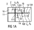
図1A〜1Dは、本発明に従ったトリガー機構の第1の実施態様を示す。トリガー機構は、吸入器1に、例えば、ドライパウダー吸入器、水滴吸入器、又は定量吸入器に、貯蔵された1回投与量の薬物の送達を作動させるため、吸入器1において使用される。トリガー機構の操作を説明するために、薬物送達の作動プロセスの連続段階を示す。
1A-1D show a first embodiment of a trigger mechanism according to the present invention. The trigger mechanism is used in the
トリガー機構は、作動フラップ11、第1のレバー12、第2のレバー13、第1のバネ14、及び第2のバネ15を含む。
The trigger mechanism includes an
作動フラップ11は、呼吸チャンネル10内に位置し、ここを経由して使用者は吸入する。作動フラップ11及びレバー12、13は、それらの端部の1つにある、ピボット111、121、131を中心にしてそれぞれ旋回されている。作動フラップ11には、そのピボットに位置する、第1のリング・セグメント112が備えられている。第1のレバー12には、そのピボットに位置する、第2のリング・セグメント122が備えられている。リング・セグメント112、122は、それぞれのピボット111、121を中心とした円の約3分の1に伸びており、それぞれのピボット111、121の表面から伸びている。
The
作動フラップ11及び第1のレバー12のピボット111及び121は、第1のレバー12の長さに対応する距離L1だけ離れている。レバー12、13の、ピボット121及び131は、第2のレバー13の長さに対応する距離L2だけ離れている。ピボット111、121、131は、共通平面内に位置している。それ故に、図1Aに示すように、作動フラップ11及びレバー12、13がこの平面に対して枢動し、同様に、それらの各ピボット111、121、131から方向付けられた場合、第1のレバー12は、作動フラップ11のピボット111の方向に伸び、第2のレバー13は、第1のレバー12のピボット121の方向に伸びる。さらに、この位置において、第1のリング・セグメント112は、第1のレバー12が上方に回転するのを拘止し、一方第2のリング・セグメント122は、第2のレバー13が下方に回転するのを拘止する。
The
第1のレバー12は、第1のレバー12のピボット121との距離X1の所で、作動フラップ11のピボット111に近い、第1のバネ14に連結される。第2のレバー13は、第2のレバー13のピボット131との距離X2の所で、第1のレバー12のピボット121に近い、第2のバネ15に連結される。それによって、第1のバネ14は、第1のレバー12の下側に位置し、一方、第2のバネ15は、第2のレバー13の上側に位置する。第2のバネ15の剛性は、第1のバネ14の剛性を上回る。
The
図1Aは、上述のように、作動フラップ11及びレバー12、13が同一平面に位置しているトリガー機構の初期状態を示す。この状態において、バネ14、15は双方が圧縮されており、第2のバネ15は、第1のバネ14よりもより多くのエネルギーを貯蔵している。作動フラップ11上に力がかかっていない場合には、作動フラップ11及びレバー12、13の枢動は、それぞれ、リング・セグメント112、122により拘止される。レバー12、13は、このように、バネ14、15によって、それぞれプレストレスされており、第2のレバー13のプレストレスは、第1のレバー12のプレストレスを上回る。
FIG. 1A shows an initial state of the trigger mechanism in which the
図1Bは、使用者が吸入をまさに始めた時のトリガー機構を示す。その吸入が、空気流B及び作動フラップ11を下方に枢動させるのに十分な圧力降下Pを引き起こす。この機構の詳細な定量的な説明を以下に示す。
FIG. 1B shows the trigger mechanism when the user has just started inhalation. That inhalation causes a pressure drop P sufficient to pivot the air flow B and the
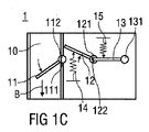
図1Cは、第1のリング・セグメント112が、第1のレバー12を解放するように、作動フラップ11が十分に枢動した場合のトリガー機構を示す。結果として、第1のバネ14は伸び、第1のレバー12を上方に枢動させる。この機構も、以下に詳細に説明される。
FIG. 1C shows the trigger mechanism when the
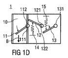
図1Dは、第2のリング・セグメント122が、第2のレバー13を解放するように、第1のレバー12が十分に枢動した場合のトリガー機構を示す。結果として、第2のバネ15は伸び、第2のレバー13を下方に枢動させる。
FIG. 1D shows the trigger mechanism when the
図1A〜1Dにて図示された作動プロセスの間、圧力降下Pにより、作動フラップ11上に及ぼされる作動力Faは、第1のバネ14に内蔵されたエネルギーを放出し、そのエネルギーが、順に、第2のバネ15に内蔵されたエネルギーを放出するために使用される。その結果、作動力Faを、バネ14、15によって及ぼされる力に、大幅に増幅することが出来る。この点は、定性的に上述されたトリガー機構の、以下の定量的解析において示される。
During the actuation process illustrated in FIGS. 1A-1D, the actuation force Fa exerted on the
作動フラップ11の面積を意味するAを用いると、圧力降下Pにより、作動フラップ11上に及ぼされる作動力Faは、Fa=P・Aである。作動力Faは、作動フラップ11上に、作動トルクTa=P・A・Zを及ぼし、ここで、Zは、作動フラップ11のピボット111と、作動力Faの事実上の作用点との間の距離である。
When A which means the area of the
第1のバネ14によって、第1のレバー12の上に及ぼされるバネ力をF1と表示すると、ピボット111での反力Y1は、Y1=(X1/L1)・F1である。図1Aに示すトリガー機構の初期状態において、作動フラップ11の枢動は、第1のリング・セグメント112と、第1のレバー12の対応する端部との間の静摩擦によって拘止される。この静摩擦は、μを摩擦係数とすると、μ・Y1=μ・(X1/L1)・F1である。ピボット111の中心からの第1のリング・セグメント112の半径をR1と表示すると、第1拘止トルクT1=R1・μ・(X1/L1)・F1によって、このように作動フラップ11の枢動は拘止される。
When the spring force exerted on the
トリガー機構が図1Bに従って動作するためには、即ち、作動フラップ11を枢動させるためには、この第1拘止トルクT1を、作動トルクTaは上回らねばならない。即ち、T1<Ta、及び、R1・μ・(X1/L1)・F1<Z・P・Aである。従って、トリガー機構によって拘止されるが、作動フラップ11によって解放され得る、第1のバネ12の力F1は、
F1 < Z・P・A・(L1/X1)/(R1・μ) (1)
によって制約され、第1のバネ14により供される作動力Faの最大増幅度は、
F1/Fa < Z・(L1/X1)/(R1・μ) (2)
によって制約される。標準的な値、A=100mm2、Z=5mm、P=1kPa、L1=40mm、X1=20mm、R1=1mm、及び、μ=0.5を代入すると、
F1 < 2N (3)
F1/Fa < 20 (4)
となる。
In order for the trigger mechanism to operate in accordance with FIG. 1B, that is, in order to pivot the
F1 <Z · P · A · (
And the maximum amplification degree of the actuation force Fa provided by the
F1 / Fa <Z · (L 1 / X 1 ) / (R 1 · μ) (2)
Constrained by Substituting standard values, A = 100 mm 2 , Z = 5 mm, P = 1 kPa, L 1 = 40 mm, X 1 = 20 mm, R 1 = 1 mm, and μ = 0.5,
F1 <2N (3)
F1 / Fa <20 (4)
It becomes.
類似の考察が、第2のリング・セグメント122を通じての、第1のレバー12と第2のレバー13との連結に適用される。
Similar considerations apply to the connection of the
第2のバネ15による第2のレバー13上へのバネ力をF2と表示すると、ピボット121での反力Y2は、Y2=(X2/L2)・F2である。第1のレバー12の枢動は、第2のリング・セグメント122と、第2のレバー13の対応する端部との間の摩擦力によって拘止される。この静摩擦力は、μ・Y2=μ・(X2/L2)・F2である。ピボット121のセンターからの、第2のリング・セグメント122の半径をR2と表示すると、第1のレバー12の枢動は、第2拘止トルクT2=R2・μ・(X2/L2)・F2により拘止される。
When the spring force exerted on the
トリガー機構が図1Cに従って動作するためには、即ち、第1のレバー12を枢動させるためには、第1のレバー12上に、第1のバネ14によって供せられるトルクX1・F1は、第2拘止トルクT2を上回らなければならない。即ち、R2・μ・(X2/L2)・F2 < X1・F1である。
To trigger mechanism operates in accordance with FIG. 1C, i.e., to pivot the
それ故、付加的な力増幅度F2/F1は、
F2/F1 < X1・(L2/X2)/(R2・μ) (5)
によって制約される。
上記と同一の標準的な値、X1=X2=20mm、L1=L2=40mm、R1=R2=1mm、μ=0.5を代入すると、
F2/F1 < 80 (6)
及び、
F2 < 160N (7)
となる。
Therefore, the additional force amplification F2 / F1 is
F2 / F1 <X1 · (
Constrained by
Substituting the same standard values as above, X 1 = X 2 = 20 mm, L 1 = L 2 = 40 mm, R 1 = R 2 = 1 mm, μ = 0.5,
F2 / F1 <80 (6)
as well as,
F2 <160N (7)
It becomes.
このようにして、F2はおよそ160Nとなる。これは、かなりの力であり、バネ14、15から放出されたエネルギーは、吸入器1を通じての1回投与量送達に、確かに使用可能である。さらにもっと力増幅度を高めるために、さらなるカスケード式トリガーエレメント及びバネを、加えることも可能である。
In this way, F2 is approximately 160N. This is a considerable force and the energy released from the
トリガー機構のさらなる使用法としては、各々のレバー12、13を吸入器機構の別個の部分に連結することがあり得る。例えば、第1のレバー12は、1回投与量のコンテナーを開けることを始動させることが可能であり、第2のレバー13は、1回投与量の送達を始動させることが可能である。第1のレバー12又は第2のレバー13のいずれかにダンピングを加えることにより、作動フラップ11の初期呼吸作動と、第2のレバー13の解放との間に、時間遅延を導入することも、また、可能である。呼吸作動に「段階的」応答を導入するために、これを使用することが可能である。
A further use of the trigger mechanism may be to connect each
レバー12、13が解放された後、使用者は、トリガー機構を再度使用する前に、双方のレバー12、13をリセットしなければならないであろう。リセット動作は、例えば空の1回投与量コンテナーを取り除くため、又は新しい1回投与量を装填するためそれを開けるなど、他の動作を使用者が吸入器1に行う場合、又は使用する前の吸入器1のプライミング動作中に、同時に起こり得る。トリガー機構によって、力がどの程度まで増幅されるかの限度は、トリガー機構をリセットする場合、使用者が、どれほど大きなエネルギーをシステムに戻せるかであると見込まれる。
After the
図1A〜1Dに示された実施態様は、バネ14、15を反対方向にリセットしなければならないという欠点を有する。この欠点は、図2A〜2Bに示された、トリガー機構の代わりの実施態様によって克服される。再び、トリガー機構が吸入器1に使用される。
The embodiment shown in FIGS. 1A-1D has the disadvantage that the
第1の実施態様と比較して、この実施態様の違いは、レバー12、13が、図2Aに示すトリガー機構の初期状態において、それらが上下に重ねられたように配置されていることである。さらにその上、第1のレバー12は作動フラップ11に固定され、それらが同時に枢動可能なように、双方が同一のピボット111を有している。バネ14、15は、レバー12、13の同一側に位置し、第2のレバー13には、第1の実施態様のリング・セグメント112、122と同一の型式の第3のリング・セグメント133が備えられている。ここで、第1のレバー12は、それのピボット111から、第2のレバー13のピボット131へ伸びている。この場合もやはり、ピボット111には、第1のリング・セグメント112が備えられ(図2A及び2B中には見えていない)、これに向かって、第2のレバー13が、それの初期位置において伸びている。
Compared to the first embodiment, the difference in this embodiment is that the
図2Aに示すトリガー機構の初期状態において、第3のリング・セグメント133は、第3のリング・セグメント133及び第1のレバー12の対応する端部との間の摩擦により、作動フラップ11及び第1のレバー12が枢動するのを拘止し、第1のリング・セグメント112は、第1のリング・セグメント112及び第2のレバー13の対応する端部との間の摩擦により、第2のレバー13が枢動するのを拘止する。
In the initial state of the trigger mechanism shown in FIG. 2A, the
使用者が、吸入によって、作動フラップ11上に十分な作動力Faを及ぼす場合、図2Bに示すように、レバー12、13は解放され、双方が上方に枢動する。
If the user exerts a sufficient actuation force Fa on the
トリガー機構をリセットするためには、レバー12、13の双方を下方に押して、リング・セグメント112、133を再度係合させる。
To reset the trigger mechanism, both
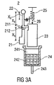
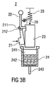
図3Aから3Dは、本発明に記載のトリガー機構の第3の実施態様を図示する。トリガー機構は自己注射器2に使用され、カートリッジ24の底部に位置する自己注射器2の投薬エレメント243を通じて、カートリッジ24に内蔵された1回投与量の薬物242の送達を作動させる。カートリッジ24は、プラグ241により密閉されている。
3A to 3D illustrate a third embodiment of a trigger mechanism according to the present invention. The trigger mechanism is used in the auto-
トリガー機構は、手動で操作する作動レバー21、中間レバー22、ピストン23、第1のバネ26、及び第2のバネ25を含む。
The trigger mechanism includes an
作動レバー21は、その端部の1つで、ピボット211を中心にして旋回されており、その反対側の端部に、トリガー・ボタンが備えられている。ピボット211の中心とトリガー・ボタンの中心との間の距離は、X5と表示される。作動レバー21には、ピボット211に位置している第1のリング・セグメント212が備えられ、第1及び第2の実施態様のリング・セグメント112、122、133と同様な型式である。
The actuating
中間レバー22には、作動レバー21のピボット211に位置している、フック形状の屈曲部が付いている。中間レバー22の第1端部は、ピストン23の方向を向いており、第2端部はピボットを含み、それを中心にして中間レバー22が旋回され、中間レバー22は、そのピボットからX3の距離のところで、第1のバネ26に接続される。屈曲部と中間レバー22のピボットとの間の距離は、X4と表示される。
The
ピストン23の一端は、カートリッジ24のプラグ241の方向を向き、他端は、第2のバネ25に接続される。ピストン23の表面には、中間レバー22の第1端部が係合することが出来るノッチが備えられる。
One end of the
ここで、トリガー機構の動作を、最初に図3A〜3Dを参照しながら定性的に説明し、後で定量的に解析する。 Here, the operation of the trigger mechanism will be first described qualitatively with reference to FIGS.
図3Aは、トリガー機構の初期状態を示す。バネ25、26の双方が圧縮されている。中間レバー22の第1端部は、ピストン23のノッチと係合し、ピストン23がプラグ241の方向に動くのを防いでいる。中間レバー22の屈曲部は、中間レバー22の枢動を拘止する第1のリング・セグメント212に連結されている。
FIG. 3A shows the initial state of the trigger mechanism. Both springs 25 and 26 are compressed. The first end of the
図3Bは、作動レバー21が、そのピボット211を中心にして枢動するように、使用者が、作動レバー21のトリガー・ボタンを十分に押した場合のトリガー機構を示す。作動レバー21が枢動するにつれて、第1のリング・セグメント212は、ついには係合が解かれ、中間レバー22を解放する。
FIG. 3B shows the trigger mechanism when the user has fully pressed the trigger button on the
図3Cは、中間レバー22が解放された後のトリガー機構を示す。第1のバネ26が伸び、中間レバー22を枢動する。中間レバー22の第1端部は、ピストン23の表面にあるノッチとの係合が解かれ、ピストン23を解放する。ここで、ピストン23は、第4のバネ25の作動の下に、プラグ241の方向へ自由に動くことが出来る。
FIG. 3C shows the trigger mechanism after the
図3Dは、ピストン23が解放された後のトリガー機構を示す。ピストン23がプラグ241へと動き、カートリッジ24の底部方向にそれを押す。それによって、それは、カートリッジ24内の薬物に、投薬エレメント243を通じて薬物の送達を推し進める圧力を及ぼす。
FIG. 3D shows the trigger mechanism after the
トリガー機構を定量的に考察するため、トリガー機構の初期状態において、中間レバー22及びピストン23上に及ぼされる、第3のバネ26及び第4のバネ25の力を、それぞれF3及びF4で表示する。
In order to quantitatively consider the trigger mechanism, the forces of the
中間レバー22の厚みは、その長さに比して無視できると仮定すると、トリガー機構の初期状態において、中間レバー22と第2のリング・セグメント212との間で、第1のバネ26によって供されるおおよその反力は、F3・(X3/X4)である。中間レバー22と第4のリング・セグメント212との間の摩擦によって引き起こされる第3の拘止トルクT3は、それゆえ、およそ、T3=R3・μ・F3・(X3/X4)であり、ここで、R3は、ピボット211の中心からの、第1のリング・セグメント212の半径である。
Assuming that the thickness of the
使用者は、この抵抗に打ち克つため、トリガー・ボタンに十分な作動力Uを与えなければならない。Uから生じる作動力は、U・X5である。 The user must apply a sufficient actuation force U to the trigger button to overcome this resistance. The actuation force resulting from U is U · X 5 .
作動レバー21は、このトルクが第3の拘止トルクT3を上回った場合、即ち、U・X5 > R3・μ・F3・(X3/X4)の場合、枢動を始める。それ故に、作動レバー21が枢動するためには、第3のバネ26の力F3は、
F3 < (X4・X5/X3)・U/(R3・μ) (8)
により制約される。
The actuating
F3 <(X 4 · X 5 / X 3) · U / (R 3 · μ) (8)
Constrained by
ピストン23を解放するために、第1のバネ26によって、中間レバー22の屈曲部に供される力F3・(X3/X4)は、μ・F4であるピストン23と中間レバー22との間の摩擦に、打ち克たなければならない。従って、F3・(X3/X4)>μ・F4ならば、ピストン23は解放される。それ故に、トリガー機構が作動するためには、第2のバネ25の力F4は、
F4 < F3・(X3/X4)/μ (9)
により制約される。
標準的な値、X5=25mm、X3=15mm、X4=30mm、μ=0.5、R3=2.5mm、及びU=1Nを代入すると、
F4 < 40N (10)
が得られる。
In order to release the
F4 <F3 · (X 3 / X 4 ) / μ (9)
Constrained by
Substituting standard values, X 5 = 25 mm, X 3 = 15 mm, X 4 = 30 mm, μ = 0.5, R 3 = 2.5 mm, and U = 1N,
F4 <40N (10)
Is obtained.
作動力U=1Nと比較すると、これにより、40倍までの力の増幅度が与えられる。増幅度は、中間レバー22の異なった配置、及び/又は、さらなる中間レバー及びバネの使用、及び/又は、中間レバー22を、ピストン23の表面にあるノッチによって連結する代わりに、「転がり」連結により、ピストン23に連結することによって、さらに高めることが出来る。
Compared with the actuation force U = 1N, this gives a force amplification of up to 40 times. The degree of amplification can be determined by a different arrangement of the
1: 吸入器
10: 呼吸チャンネル
11: 作動フラップ
12、13、22: レバー
14、15、25、26: バネ
111、121、131、211: ピボット
112、122、133、212: リング・セグメント
2: 自己注射器
21: 作動レバー
22: 中間レバー
23: ピストン
24: カートリッジ
241: プラグ
242: 薬物
243: 投薬エレメント
X1、X2、X3、X4、X5、L1、L2、Z: 距離
B: 空気流
P: 圧力降下
F3、U: 作動力
F1、F2、F3、F4: バネ力
Y1、Y2: 反力
Ta: 作動トルク
T1、T2、T3: 拘止トルク
R1、R2、R3: 半径
μ: 摩擦係数
1: Inhaler 10: Breathing channel 11: Actuating flaps 12, 13, 22:
Claims (17)
請求項1に記載のトリガー機構。 Before the latching element is actuated (Fa, U), it is characterized in that at least one trigger element is held in its prestressed state,
The trigger mechanism according to claim 1.
Applications Claiming Priority (3)
| Application Number | Priority Date | Filing Date | Title |
|---|---|---|---|
| EP09003805.0 | 2009-03-17 | ||
| EP09003805A EP2229971A1 (en) | 2009-03-17 | 2009-03-17 | Trigger mechanism for a drug delivery device |
| PCT/EP2010/053433 WO2010106090A1 (en) | 2009-03-17 | 2010-03-17 | Trigger mechanism for a drug delivery device |
Publications (2)
| Publication Number | Publication Date |
|---|---|
| JP2012520706A true JP2012520706A (en) | 2012-09-10 |
| JP2012520706A5 JP2012520706A5 (en) | 2013-04-25 |
Family
ID=40720015
Family Applications (1)
| Application Number | Title | Priority Date | Filing Date |
|---|---|---|---|
| JP2012500231A Pending JP2012520706A (en) | 2009-03-17 | 2010-03-17 | Trigger mechanism for drug delivery devices |
Country Status (9)
| Country | Link |
|---|---|
| US (1) | US9427535B2 (en) |
| EP (2) | EP2229971A1 (en) |
| JP (1) | JP2012520706A (en) |
| CN (1) | CN102355917A (en) |
| AU (1) | AU2010224874A1 (en) |
| BR (1) | BRPI1009544A2 (en) |
| CA (1) | CA2755455A1 (en) |
| IL (1) | IL214987A0 (en) |
| WO (1) | WO2010106090A1 (en) |
Cited By (1)
| Publication number | Priority date | Publication date | Assignee | Title |
|---|---|---|---|---|
| JP2018501265A (en) * | 2014-12-23 | 2018-01-18 | ギリアード サイエンシーズ, インコーポレイテッド | Process for preparing an ASK1 inhibitor |
Families Citing this family (6)
| Publication number | Priority date | Publication date | Assignee | Title |
|---|---|---|---|---|
| DE602005009005D1 (en) * | 2004-10-21 | 2008-09-25 | Novo Nordisk As | INJECTION DEVICE WITH MEANS OF REPORTING THE TIME SINCE THE LAST INJECTION |
| JP5603335B2 (en) * | 2008-08-29 | 2014-10-08 | ノボ・ノルデイスク・エー/エス | Medical syringe with time delay indicator |
| WO2017087888A1 (en) | 2015-11-18 | 2017-05-26 | President And Fellows Of Harvard College | Systems and methods for monitoring, managing, and treating asthma and anaphylaxis |
| WO2017112476A2 (en) * | 2015-12-21 | 2017-06-29 | 3M Innovative Properties Company | Dose release firing systems and medicinal inhalers comprising same |
| WO2017112451A1 (en) | 2015-12-21 | 2017-06-29 | 3M Innovative Properties Company | Auto-reset dose release firing systems, medicinal inhalers comprising same, and methods of using same |
| US11278667B2 (en) * | 2017-06-20 | 2022-03-22 | Zealand Pharma A/S | Time delay mechanism for a hydraulic drug delivery device |
Citations (1)
| Publication number | Priority date | Publication date | Assignee | Title |
|---|---|---|---|---|
| JP2001525714A (en) * | 1997-05-23 | 2001-12-11 | ピィ・エイ・ノレッジ・リミテッド | Inhaler mechanism |
Family Cites Families (10)
| Publication number | Priority date | Publication date | Assignee | Title |
|---|---|---|---|---|
| GB9025654D0 (en) * | 1990-11-26 | 1991-01-09 | Riker Laboratories Inc | Device |
| US6823863B2 (en) | 2000-03-18 | 2004-11-30 | Astrazeneca Ab | Inhaler |
| GB2360216A (en) * | 2000-03-18 | 2001-09-19 | Astrazeneca Uk Ltd | Inhaler |
| GB0023845D0 (en) * | 2000-09-29 | 2000-11-15 | Pa Knowledge Ltd | Dosing device |
| GB0304000D0 (en) * | 2003-02-21 | 2003-03-26 | Clinical Designs Ltd | Dispenser |
| JP4668982B2 (en) * | 2004-03-30 | 2011-04-13 | イーライ リリー アンド カンパニー | Drug delivery device with gear set having drive part with opening |
| US7618393B2 (en) | 2005-05-03 | 2009-11-17 | Pharmajet, Inc. | Needle-less injector and method of fluid delivery |
| GB0600070D0 (en) * | 2006-01-04 | 2006-02-15 | Campling Nicholas J | Dose counter |
| FR2924352B1 (en) * | 2007-12-03 | 2010-01-29 | Valois Sas | DEVICE FOR DISPENSING FLUID PRODUCT. |
| CN201182811Y (en) * | 2007-12-28 | 2009-01-21 | 国家纳米技术与工程研究院 | Dry powder inhaler convenient for carrying |
-
2009
- 2009-03-17 EP EP09003805A patent/EP2229971A1/en not_active Withdrawn
-
2010
- 2010-03-17 US US13/202,824 patent/US9427535B2/en not_active Expired - Fee Related
- 2010-03-17 JP JP2012500231A patent/JP2012520706A/en active Pending
- 2010-03-17 BR BRPI1009544A patent/BRPI1009544A2/en not_active IP Right Cessation
- 2010-03-17 CN CN2010800125670A patent/CN102355917A/en active Pending
- 2010-03-17 AU AU2010224874A patent/AU2010224874A1/en not_active Abandoned
- 2010-03-17 WO PCT/EP2010/053433 patent/WO2010106090A1/en active Application Filing
- 2010-03-17 EP EP10709002A patent/EP2408496A1/en not_active Withdrawn
- 2010-03-17 CA CA2755455A patent/CA2755455A1/en not_active Abandoned
-
2011
- 2011-09-05 IL IL214987A patent/IL214987A0/en unknown
Patent Citations (1)
| Publication number | Priority date | Publication date | Assignee | Title |
|---|---|---|---|---|
| JP2001525714A (en) * | 1997-05-23 | 2001-12-11 | ピィ・エイ・ノレッジ・リミテッド | Inhaler mechanism |
Cited By (1)
| Publication number | Priority date | Publication date | Assignee | Title |
|---|---|---|---|---|
| JP2018501265A (en) * | 2014-12-23 | 2018-01-18 | ギリアード サイエンシーズ, インコーポレイテッド | Process for preparing an ASK1 inhibitor |
Also Published As
| Publication number | Publication date |
|---|---|
| WO2010106090A1 (en) | 2010-09-23 |
| BRPI1009544A2 (en) | 2016-03-22 |
| CN102355917A (en) | 2012-02-15 |
| US20120103329A1 (en) | 2012-05-03 |
| AU2010224874A1 (en) | 2011-10-06 |
| EP2408496A1 (en) | 2012-01-25 |
| EP2229971A1 (en) | 2010-09-22 |
| US9427535B2 (en) | 2016-08-30 |
| IL214987A0 (en) | 2011-11-30 |
| CA2755455A1 (en) | 2010-09-23 |
Similar Documents
| Publication | Publication Date | Title |
|---|---|---|
| JP2012520706A (en) | Trigger mechanism for drug delivery devices | |
| EP1320397B1 (en) | Medical Inhalation-Device | |
| JP4350308B2 (en) | Inhaler | |
| US9125988B2 (en) | Medicament delivery device | |
| AU732869B2 (en) | Device for use with metered dose inhalers (MDIs) | |
| EP2504051B1 (en) | Nebulizer | |
| EP0984805B1 (en) | Inhaler mechanism | |
| RU2457870C2 (en) | Breath-actuated inhaler drive | |
| KR101849181B1 (en) | Inhaler | |
| CA2401594A1 (en) | Inhaler | |
| US20030116155A1 (en) | Inhaler | |
| AU2001244904A1 (en) | Inhaler | |
| NZ254959A (en) | Inhaler; breath-actuated aerosol dispenser, spring providing the priming force is held partially compressed in a cage | |
| JP7423642B2 (en) | Intake synchronized fluid product dispensing device and method of assembling the fluid product dispensing device | |
| RU2009105643A (en) | MEDICINE DISTRIBUTION DEVICE | |
| JP7463384B2 (en) | Intake-synchronized fluid product discharge device | |
| AU2001244905B2 (en) | Inhaler | |
| US20100083960A1 (en) | Activating Mechanism | |
| CN111526909A (en) | Blocking device | |
| JP7459096B2 (en) | Inspiration synchronized fluid administration device | |
| EP1386854A1 (en) | Inhaler valve mechanism |
Legal Events
| Date | Code | Title | Description |
|---|---|---|---|
| A521 | Request for written amendment filed |
Free format text: JAPANESE INTERMEDIATE CODE: A523 Effective date: 20130308 |
|
| A621 | Written request for application examination |
Free format text: JAPANESE INTERMEDIATE CODE: A621 Effective date: 20130308 |
|
| A977 | Report on retrieval |
Free format text: JAPANESE INTERMEDIATE CODE: A971007 Effective date: 20140109 |
|
| A131 | Notification of reasons for refusal |
Free format text: JAPANESE INTERMEDIATE CODE: A131 Effective date: 20140121 |
|
| A02 | Decision of refusal |
Free format text: JAPANESE INTERMEDIATE CODE: A02 Effective date: 20140805 |